EP3580059B1 - Tool set having deflection compensation - Google Patents
Tool set having deflection compensation Download PDFInfo
- Publication number
- EP3580059B1 EP3580059B1 EP18703997.9A EP18703997A EP3580059B1 EP 3580059 B1 EP3580059 B1 EP 3580059B1 EP 18703997 A EP18703997 A EP 18703997A EP 3580059 B1 EP3580059 B1 EP 3580059B1
- Authority
- EP
- European Patent Office
- Prior art keywords
- tool
- tool member
- amount
- die
- positional deflection
- Prior art date
- Legal status (The legal status is an assumption and is not a legal conclusion. Google has not performed a legal analysis and makes no representation as to the accuracy of the status listed.)
- Active
Links
Images


Classifications
-
- B—PERFORMING OPERATIONS; TRANSPORTING
- B22—CASTING; POWDER METALLURGY
- B22F—WORKING METALLIC POWDER; MANUFACTURE OF ARTICLES FROM METALLIC POWDER; MAKING METALLIC POWDER; APPARATUS OR DEVICES SPECIALLY ADAPTED FOR METALLIC POWDER
- B22F3/00—Manufacture of workpieces or articles from metallic powder characterised by the manner of compacting or sintering; Apparatus specially adapted therefor ; Presses and furnaces
- B22F3/02—Compacting only
- B22F3/03—Press-moulding apparatus therefor
-
- B—PERFORMING OPERATIONS; TRANSPORTING
- B30—PRESSES
- B30B—PRESSES IN GENERAL
- B30B11/00—Presses specially adapted for forming shaped articles from material in particulate or plastic state, e.g. briquetting presses, tabletting presses
- B30B11/02—Presses specially adapted for forming shaped articles from material in particulate or plastic state, e.g. briquetting presses, tabletting presses using a ram exerting pressure on the material in a moulding space
-
- B—PERFORMING OPERATIONS; TRANSPORTING
- B30—PRESSES
- B30B—PRESSES IN GENERAL
- B30B15/00—Details of, or accessories for, presses; Auxiliary measures in connection with pressing
- B30B15/02—Dies; Inserts therefor; Mounting thereof; Moulds
- B30B15/022—Moulds for compacting material in powder, granular of pasta form
-
- B—PERFORMING OPERATIONS; TRANSPORTING
- B30—PRESSES
- B30B—PRESSES IN GENERAL
- B30B15/00—Details of, or accessories for, presses; Auxiliary measures in connection with pressing
- B30B15/06—Platens or press rams
- B30B15/065—Press rams
-
- B—PERFORMING OPERATIONS; TRANSPORTING
- B30—PRESSES
- B30B—PRESSES IN GENERAL
- B30B15/00—Details of, or accessories for, presses; Auxiliary measures in connection with pressing
- B30B15/06—Platens or press rams
- B30B15/065—Press rams
- B30B15/067—Press rams with means for equalizing the pressure exerted by a plurality of press rams
-
- B—PERFORMING OPERATIONS; TRANSPORTING
- B33—ADDITIVE MANUFACTURING TECHNOLOGY
- B33Y—ADDITIVE MANUFACTURING, i.e. MANUFACTURING OF THREE-DIMENSIONAL [3D] OBJECTS BY ADDITIVE DEPOSITION, ADDITIVE AGGLOMERATION OR ADDITIVE LAYERING, e.g. BY 3D PRINTING, STEREOLITHOGRAPHY OR SELECTIVE LASER SINTERING
- B33Y80/00—Products made by additive manufacturing
-
- B—PERFORMING OPERATIONS; TRANSPORTING
- B22—CASTING; POWDER METALLURGY
- B22F—WORKING METALLIC POWDER; MANUFACTURE OF ARTICLES FROM METALLIC POWDER; MAKING METALLIC POWDER; APPARATUS OR DEVICES SPECIALLY ADAPTED FOR METALLIC POWDER
- B22F3/00—Manufacture of workpieces or articles from metallic powder characterised by the manner of compacting or sintering; Apparatus specially adapted therefor ; Presses and furnaces
- B22F3/02—Compacting only
- B22F3/03—Press-moulding apparatus therefor
- B22F2003/033—Press-moulding apparatus therefor with multiple punches working in the same direction
-
- B—PERFORMING OPERATIONS; TRANSPORTING
- B22—CASTING; POWDER METALLURGY
- B22F—WORKING METALLIC POWDER; MANUFACTURE OF ARTICLES FROM METALLIC POWDER; MAKING METALLIC POWDER; APPARATUS OR DEVICES SPECIALLY ADAPTED FOR METALLIC POWDER
- B22F2998/00—Supplementary information concerning processes or compositions relating to powder metallurgy
- B22F2998/10—Processes characterised by the sequence of their steps
-
- B—PERFORMING OPERATIONS; TRANSPORTING
- B22—CASTING; POWDER METALLURGY
- B22F—WORKING METALLIC POWDER; MANUFACTURE OF ARTICLES FROM METALLIC POWDER; MAKING METALLIC POWDER; APPARATUS OR DEVICES SPECIALLY ADAPTED FOR METALLIC POWDER
- B22F2999/00—Aspects linked to processes or compositions used in powder metallurgy
-
- Y—GENERAL TAGGING OF NEW TECHNOLOGICAL DEVELOPMENTS; GENERAL TAGGING OF CROSS-SECTIONAL TECHNOLOGIES SPANNING OVER SEVERAL SECTIONS OF THE IPC; TECHNICAL SUBJECTS COVERED BY FORMER USPC CROSS-REFERENCE ART COLLECTIONS [XRACs] AND DIGESTS
- Y02—TECHNOLOGIES OR APPLICATIONS FOR MITIGATION OR ADAPTATION AGAINST CLIMATE CHANGE
- Y02P—CLIMATE CHANGE MITIGATION TECHNOLOGIES IN THE PRODUCTION OR PROCESSING OF GOODS
- Y02P10/00—Technologies related to metal processing
- Y02P10/25—Process efficiency
Definitions
- This disclosure relates to an improved tool set for the compaction of powder metal components and related methods of producing a powder metal compact using these improved tool set.
- Metal components can be formed in a number of different ways.
- One of these ways for fabricating metal components is powder metallurgy. While various techniques exist for forming powder metal into components, many components are formed by the uni-axial compaction of powder metal in a tool and die set in a press to form a preform that is then ejected and sintered. Although some secondary operations may be performed on the part after sintering, the as-sintered component is often very close to final dimensions. Thus, powder metallurgy offers an economical way to produce large volumes of components that are near net shape.
- JP H07 88699 A relates to a die assembly which should prevent a green compact of cracking.
- the die assembly comprises a lower punch with a fixed punch and a floating punch. Under load the displacement of the floating punch is greater than of the fixed punch.
- CN201776443U relates to press assembly which should prevent the metal or ceramic green compact of cracking by building compensation mechanism within the plurality of lower plungers.
- the compensation mechanisms equalise the deflection motion of the plurality of plungers during the press releasing.
- the tool and die set in the press typically includes multiple tool members, inserted into the top and bottom of the die cavity, that are actuated by the press to compact the powder metal into the preform and then to effectuate ejection of the metal preform.
- These tools are often separately movable and engage different surfaces of the powder metal preform.
- these various tool members exhibit an identical or nearly identical elastic response.
- the design of the preform often results in at least some the various tool members being subjected to different load conditions.
- the powder metal preform often has a geometry requiring a number of powder metal columns some of which have differing heights.
- the difference in the column height across the sections means that different tool members may experience different loads and/or amounts of deflection.
- a taller vertical column of powder metal will respond differently that a shorter vertical column of powder metal. There are many reasons for this including the increased surface area against which the powder may be compressed against the side wall of the die or another tool member.
- the tool members will often need to exert more pressure on a taller column than a shorter column in order to compress the taller column to a roughly equal density to that of the shorter column.
- the taller column - shorter column example is provided as one example, but it should be appreciated that it is not only a height-based inquiry and design considerations are frequently more complicated than simply height.
- the amount of side wall contact will alter the manner in which a particular column will be compacted. So a first feature having a smaller amount of side wall contact than a second feature having a greater amount of side wall contact may require less pressure to compact to similar density, even if the first and second features are the same height as one another.
- this differential tool deflection means that, under the applied load to compact the powder metal into the preform, the tools may all exhibit some amount of differential deflection during elastic deformation and then, once the load is released, the tools will quickly deflect back to their unstressed length.
- One possible result of this equal elasticity, but unequal deflection, design is that, upon removing the load of the press, the position on the surfaces of the tools that form the part will deflect to varying degrees. In many instances, this differential deflection after the load is removed will place stress on the preform, causing the formation of cracks in the preform.
- the improved tool and die set provide an asymmetrical deflection of the various tool members to avoid problems such as the aforementioned cracking of the preform once the compressive load is removed. It will be appreciated that when describing the elastic response or the deflection of the tool members in this application that this elastic response or deflection is not based solely on the mechanical response or elastic deformation of the tool members, but also may include the mechanical response or elastic deformation of other components of the respective tool set such as adaptors that support the tool members.
- One aspect of the invention relates to a method of using a tool and die set as defined by the appended independent claim.
- At least two of the tool members in the group of the upper tool member(s) or the group of the lower tool member(s) may have an asymmetrical elastic response to the compressive load.
- the preform includes a plurality of sections with at least two of the plurality of sections having different heights and the different deflections result in partial stripping of at least one of the sections from at least one of the tool members.
- different compressive loads may be applied by the different tool members, and if the positional deflection of the tool members are not unequal, then one of the tools may undesirably relax when the compressive force is lifted, instigating a crack in the preform under stress.
- an asymmetrical deflection may be used to help maintain the structural integrity of the preform after the load is removed.
- the first amount of positional deflection is greater than the second amount of positional deflection and wherein the first amount of positional deflection may be between 0.02 mm to 0.2mm different from the second amount of positional deflection.
- the plurality of tool members may further include a third tool member and the third tool member may have a third elastic response under the compressive load resulting in a third amount of positional deflection in the third tool member.
- This third amount of positional deflection may be different than the first amount of positional deflection and the second amount of positional deflection or may be the same as one of the two.
- the first tool member and the second tool member is included in the group of lower tool members.
- the lower tool set may include a first adaptor supporting the first tool member and a second adaptor supporting the second tool member.
- the first adaptor may at least partially account for the first amount of positional deflection of the first tool member and the second adaptor may at least partially account for the second amount of positional deflection of the second tool member.
- the tool members plus their respective adaptors may dictate the overall elastic response and positional deflection of any particular tool member.
- a first upper surface of the first tool member i.e., the first preform-contacting surface
- a second upper surface of the second tool member i.e., the second preform-contacting surface
- the method may further include the step of ejecting the preform from the die cavity by raising the upper surfaces of the at least one lower tool member to be level with the top side of the die. Further, they may relax to an extent such that a gap is created between the second tool member and the preform.
- the gap may be 0.02 mm to 0.2 mm, for example.
- One aspect of the invention relates to a tool and die set for pressing a metal powder preform as defined by the appended independent claim.
- the plurality of tool members may further include a third tool member and the third tool member may have a third elastic response under the compressive load resulting in a third amount of positional deflection in the third tool member.
- the third amount of positional deflection may be different than the first amount of positional deflection and the second amount of positional deflection or may be the same as one of the two.
- the first amount of positional deflection is greater than the second amount of positional deflection.
- the first amount of deflection may be between 0.02 mm and 0.2 mm different from the second amount of positional deflection.
- the lower tool set may include a first adaptor supporting the first tool member and may further include a second adaptor supporting the second tool member.
- the first adaptor may at least partially account for the first amount of positional deflection of the first tool member and the second adaptor may at least partially account for the second amount of positional deflection of the second tool member.
- those adaptors may be formed in a number of ways to help provide the asymmetrical elasticity response.
- one or more of adaptors may be formed by additive manufacturing and/or by three-dimensional printing.
- first upper surface of the first tool member is positioned in the die cavity lower than a second upper surface of the second tool member relative to the top side of the die under the compressive load. Then, upon release of the compressive load, the first tool member relaxes the first amount of positional deflection and the second tool member relaxes the second amount of positional deflection such that the second tool member does not apply a force upon relaxation to the preform resulting in cracking.
- a tool and die set and related method of use in which at least one of the upper or lower tool sets is provided with an uneven or asymmetric elastic response.
- the differential positional deflection of the tool members during compression and relaxation helps to avoid the instigation of cracks in the preform, such as those cracks that may form when one of the tools compress and relaxes more than the other as a result of compacting powder columns of various heights.
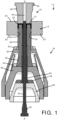
- a tool and die set 10 ( FIG. 1 ) is illustrated for forming a preform 12 from powder metal.
- the tool and die set 10 is received in a press (not shown) that will actuate the tool and die set 10 to form the preform 12 under a compressive load as will be described in greater detail below.
- the exemplary tool and die set 10 includes a die 14, an upper tool set 16, and a lower tool set 18. These parts are generally aligned along a central axis A-A, which also defines the uniaxial direction along which the various components of the tool and die set 10 may be separately actuated by the press (that is, raised or lowered relative to one another).
- the die 14 includes a die body 20 extending from a top side 22 to a bottom side 24.
- a die cavity 26 extends in an axial direction through the die body 20 from the top side 22 to the bottom side 24 of the die 14.
- the die cavity 26 is generally uniform in profile from the top side 22 to the bottom side 24 and has a section in a direction perpendicular to the central axis A-A that corresponds to an outer periphery of the preform 12. This profile of the die cavity 26 also accommodates the reception of the upper tool set 16 and the lower tool set 18 from the top side 22 and the bottom side 24.
- the die body 20 may be formed from a single material; however, in many instances, the die cavity 26 may be defined by an insert section received in another surrounding section, such that the insert may be made from a hardened material, while the surrounding section may be made from another material.
- the upper tool set 16 as illustrated in the exemplary embodiment includes a single upper punch 28 (as an upper tool member).
- the upper punch 28 has an upper side which includes a flange 30 for clamping (likely into an adaptor that is driven by the press) and has a lower preform-contacting surface 32 with an outer periphery that corresponds to the periphery of the die cavity 26 in which the lower end of the upper punch 28 will be received.
- the upper punch 28 also includes a central axially-extending opening 34 formed therein that will receive a core rod in the lower tool set 18.
- the single upper punch 28 is merely one exemplary tool member from the exemplary configuration and that, in other tool and die sets there may be additional tool members in the upper tool set. It will be further appreciated that when referring to a tool set (regardless of whether the tool set is an upper or lower tool set), the tool set may both include one or more tool members such as, for example, punches and core rods as well as, in many cases, corresponding adaptors and adaptor clamps to which these tool member(s) may be intermediately connected to before their mechanical attachment to the parts of the press (for example, a platen).
- tool members such as, for example, punches and core rods
- adaptors and adaptor clamps to which these tool member(s) may be intermediately connected to before their mechanical attachment to the parts of the press (for example, a platen).
- the lower tool set 18 includes four separately movable portions.
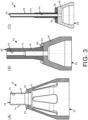
- the first, outer portion 36 is separately illustrated in FIG. 3A and includes a lower outer punch 38 and a corresponding lower outer adaptor 40 and a lower outer clamp ring 42.
- the second, middle portion 44 is separately illustrated in FIG. 3B and includes a lower middle punch 46 and a corresponding lower middle adaptor 48 and a lower middle clamp ring 50.
- the third, inner portion 52 is separately illustrated in FIG. 3C and includes a lower inner punch 54 and a corresponding lower inner adaptor 56 and a lower inner clamp ring 58.
- the fourth central core rod portion is not illustrated FIGS. 3A through 3C , but is shown in FIG. 1 , and includes a core rod 60.
- the various sections of the lower tool set 18 are nested into one another such that various corresponding side surfaces of adjacent tool members are slidably received next to one another.
- the inner portion 52 is nested around the core rod section such that a radially outward facing surface 62 of the core rod 60 is positioned adjacent to a radially inward facing surface 64 of the lower inner punch 54 (lower tool member).
- the middle portion 44 is nested around the inner portion 52 such that a radially outward facing surface 66 of the lower inner punch 54 is positioned adjacent to a radially inward facing surface 68 of the lower middle punch 46 (lower tool member).
- the outer portion 36 is nested around the middle portion 44 such that a radially outward facing surface 70 of the lower middle punch 46 is positioned adjacent to a radially inward facing surface 72 of the lower outer punch 38 (lower tool member).
- a radially outward facing surface 74 of the lower outer punch 38 is positioned adjacent the radially inward facing surface 76 of the die cavity 26 of the die 14.
- each of the lower outer punch 38, the lower middle punch 46, and the lower inner punch 54 despite their different sizes and geometries, have similar features.
- each of the lower outer punch 38, the lower middle punch 46, and the lower inner punch 54 have a corresponding preform-contacting surface 78, 80, and 82 at an upper end of the respective punches and a corresponding flange 84, 86, and 88 for clamping each respective punch 38, 46, and 54 to its respective adaptor 40, 48, and 56 via its respective clamp ring 42, 50, and 58.
- each of the outer portion 36, the middle portion 44, and the inner portion 52 have an unloaded height from a respective lower end 90, 92, and 94 of the respective adaptor 40, 48, and 56 to the preform-contacting surface 78, 80, and 82 at the upper end of the respective punch 38, 46, and 54.
- a uniaxial compressive load in the disclosed tool and die set 10 there are differing amounts of deflection between the unloaded heights and the loaded heights (from the respective bottoms of the adaptors to the upper pre-form contact surfaces) across the various portions. This effectively means that there are different amounts of positional deflection that occur under compression and subsequent relaxation across at least some of the portions.
- the adaptors and/or punches may be designed to have different elastic responses.
- the lower outer adaptor 40 is formed with openings in the wall that can be used to alter the elastic response.
- the tool members or adaptors may be formed in various ways (for example, additive manufacturing or three-dimensional printing) to create this difference in elasticity and positional deflection among at least some of the tools.
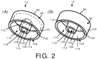
- the preform 12 is generally puck-shaped, having a top disc-like section 96 having an upwardly axially facing surface 98 and a downwardly axially facing surface 100.
- the disc-like section 98 has an inner circular wall 102 and an outer circular wall 104 extending downwardly from the bottom side thereof to an axially facing inner wall surface 106 and an axially facing outer wall surface 108, respectively.
- a recess 110 is established on the bottom side of the preform 12 that is defined by the space between a radially outward facing surface 112 of the inner circular wall 102, a radially inward facing surface 114 of the outer circular wall 104, and the downwardly axially facing surface 100 of the top disc-like section 96.
- a circular through hole 116 having a radially inward facing wall 118 extends from the upwardly axially facing surface 98 through the inner circular wall 102 to the axially facing inner wall surface 106.
- the preform 12 also has a radially outward facing surface 120 on the outer circular wall 104 that defines the outer horizontal periphery of the preform 12.
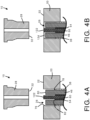
- FIGS. 4A through 4E the method of using the exemplary tool and die set 10 to form the exemplary preform 12 is now described in greater detail with reference to FIGS. 4A through 4E .
- the tool and die set 10 is shown in detail in the region in which the preform 12 will be compacted.
- FIG. 4A the various members of the tool and die set 10 is illustrated in the fill position.
- the lower preform-contacting surface 32 of the upper punch 28 is withdrawn from the die cavity 26 of the die 14 and the tool members of the lower tool set 18 are in their fill positions. More specifically, an upper surface 122 of the core rod 60 is flush with the top side 22 of the die 14 and the preform-contacting surfaces 78, 80, and 82 of the lower outer punch 38, the lower middle punch 46, and the lower inner punch 54, respectively, are downwardly spaced a vertical distance from the top side 22 of the die 14.
- each vertical spacing is established to powder fill for each of the respective columns for forming the preform 12.
- each vertical spacing may be approximately 1.8 times the final height dimensions of the respective column of the preform 12 depending on the flowability of the uncompressed powder metal and the compressive response of the powder metal.
- the specific preform geometry does not require powder metal columns to be shifted upward because there is not a complex, multipart upper tool set.
- those having skill in the art will know the manner in which the fill should be performed in order to establish the final preform geometry and it is contemplated that more complex fill patterns may be undertaken than those illustrated in the exemplary case.
- the powder metal 124 may comprise some amount of non-metallic binder, wax, and/or lubricant that may help to adjust the flowability of the powder metal 124, assist in maintaining the geometry of the preform 12 after compaction (prior to the preform 12 being sintered and the material likely being burned off), and assist in the ejection of the preform 12 from the tool and die set 10 as will be described in greater detail below.
- the die cavity 26 is filled with a powder metal 124 that is to be subsequently compacted into the preform 12.
- a feed shoe (not shown) may come in flush along the top side 22 of the die 14 and go over the die cavity 26 to fill the die cavity 26 with the powder metal 124 as illustrated in FIG. 4B and level the top surface of the powder metal to be even with the planar top side 22 of the die 14 and the upper surface 122 of the core rod 60 (which designates a vertical column where powder metal is not received that will be a through hole in the preform 12.
- the upper tool set 16 and the lower tool set 18 are moved towards one another to apply a compressive force to the powder metal 124 and form the preform 12 as illustrated in FIG. 4C .
- this involves lowering the upper punch 28 into the die cavity 26 such that it compresses the powder metal 124 downward with the core rod 60 entering the central axially-extending opening 34 while the lower outer punch 38, the lower middle punch 46, and the lower inner punch 54 are simultaneously raised to upwardly compress the powder metal 124.
- the lower outer punch 38 and the lower inner punch 54 are lifted the same amount, while the lower middle punch 46 is raised a different and lesser amount than the other two lower punches in accordance with the desired vertical column height of the preform 12 in each of their respective sections.
- the various surfaces of the preform 12 are defined by the following surfaces of the tool members.
- the upwardly axially facing surface 98 is defined by the lower preform-contacting surface 32 of the upper punch 28.
- the radially inward facing wall 118 of the circular through hole 116 is formed by the radially outward facing surface of the core rod 60.
- the radially outward facing surface 120 on the outer circular wall 104 is defined by the radially inward facing surface 76 of the die cavity 26 of the die 14.
- the axially facing outer wall surface 108, the downwardly axially facing surface 100, and the axially facing inner wall surface 106 are formed by the preform-contacting surfaces 78, 80, and 82 of the lower outer punch 38, the lower middle punch 46, and the lower inner punch 54, respectively.
- the radially inward facing surface 114 of the outer circular wall 104 and the radially outward facing surface 112 of the inner circular wall 102 are defined by the radially outward facing surface 70 of the lower middle punch 46 and the radially inward facing surface 68 of the lower middle punch 46, respectively.
- the amount of positional deflection across the tool members of the preform contacting surfaces in at least one of the upper tool set and the lower tool set are used to achieve asymmetrical elasticity across at least some of the various tool members.
- the preform-contacting surfaces 78 and 82 of the lower outer punch 38 and the lower inner punch 54 with their respective adaptors 40 and 56 are engineered to result in equal positional deflection of preform-contacting surfaces 78 and 82 upon compression and relaxation.
- the preform-contacting surface 80 of the lower middle punch 46 is engineered to have less positional deflection than the preform-contacting surfaces 78 and 82 of the lower outer punch 38 and the lower inner punch 54.
- this difference is still relatively small in magnitude, for example, in a range of 0.02 mm to 0.2 mm different or, more particularly in some forms, within approximately 0.2 mm of one another.
- FIG. 4D the compressive force has been withdrawn after the preform 12 is formed.
- the lower punches 38, 46, and 54 relax.
- the lower outer punch 38 and the lower inner punch 54 relax approximately the same amount which is greater than the elastic relaxation of the lower middle punch 46.
- a gap 126 is created between the preform 12 and the preform-contacting surface 80 of the lower middle punch 46 as the lower outer punch 38 and the lower inner punch 54 lift the preform 12 relative to the inner middle punch 46.
- the gap 126 may be 0.02 mm to 0.2 mm, for example.
- the preform 12 may then be ejected as in FIG. 4E .
- the upper surfaces of all of the lower tool members that is, the preform contacting surfaces 78, 80,and 82 of punches 38, 46, and 54 and the upper surface 122 of the core rod 60
- the preform 12 is removed from the tool and die set 10 and may be subsequently processed - typically sintered - in order to form a final sintered powder metal part.
- this tooling arrangement and described arrangement is exemplary only and the particular geometry of the preform will dictate the number, types, and arrangement of the various components and the upper and lower tool sets. Different compact forms will have different tooling arrangements and it is contemplated that the methods and principles described herein are workable with different preform geometries. For example, if there are two through holes in the preform, there may be two core rods and different numbers or types of punches.
- a tool and die set and related method of use of the same is described for the formation of a powder metal preform.
- the disclosed system intentionally creates differential responses across at least some of the tool members in order to help avoid cracking of the preform.
Landscapes
- Engineering & Computer Science (AREA)
- Mechanical Engineering (AREA)
- Manufacturing & Machinery (AREA)
- Chemical & Material Sciences (AREA)
- Materials Engineering (AREA)
- Powder Metallurgy (AREA)
Description
- This application claims the benefit of the filing date of
United States Provisional Patent Application No. 62/456,495 entitled "Tool Set Having Deflection Compensation" filed on February 8, 2017 - This disclosure relates to an improved tool set for the compaction of powder metal components and related methods of producing a powder metal compact using these improved tool set.
- Metal components can be formed in a number of different ways. One of these ways for fabricating metal components is powder metallurgy. While various techniques exist for forming powder metal into components, many components are formed by the uni-axial compaction of powder metal in a tool and die set in a press to form a preform that is then ejected and sintered. Although some secondary operations may be performed on the part after sintering, the as-sintered component is often very close to final dimensions. Thus, powder metallurgy offers an economical way to produce large volumes of components that are near net shape.
-
DE 10 2015 201 966 A1 relates to a press with conical stamps. It is there proposed that stamps should have equal lengths and equal elasticity. -
JP H07 88699 A -
CN201776443U relates to press assembly which should prevent the metal or ceramic green compact of cracking by building compensation mechanism within the plurality of lower plungers. The compensation mechanisms equalise the deflection motion of the plurality of plungers during the press releasing. - While the fabrication of powder metal components appears ostensibly simple, there are, in fact, many challenges when the fabrication steps are examined in greater detail.
- For example, the tool and die set in the press typically includes multiple tool members, inserted into the top and bottom of the die cavity, that are actuated by the press to compact the powder metal into the preform and then to effectuate ejection of the metal preform. These tools are often separately movable and engage different surfaces of the powder metal preform. In the current state of the art, these various tool members exhibit an identical or nearly identical elastic response.
- However, the design of the preform often results in at least some the various tool members being subjected to different load conditions. As one example, the powder metal preform often has a geometry requiring a number of powder metal columns some of which have differing heights. When a preform having this type of geometry is compacted, the difference in the column height across the sections means that different tool members may experience different loads and/or amounts of deflection. For example, during compaction a taller vertical column of powder metal will respond differently that a shorter vertical column of powder metal. There are many reasons for this including the increased surface area against which the powder may be compressed against the side wall of the die or another tool member. So the tool members will often need to exert more pressure on a taller column than a shorter column in order to compress the taller column to a roughly equal density to that of the shorter column. The taller column - shorter column example is provided as one example, but it should be appreciated that it is not only a height-based inquiry and design considerations are frequently more complicated than simply height. As another example, the amount of side wall contact will alter the manner in which a particular column will be compacted. So a first feature having a smaller amount of side wall contact than a second feature having a greater amount of side wall contact may require less pressure to compact to similar density, even if the first and second features are the same height as one another.
- In any event, it is the case that in the current state of the art, despite the tool members having identical or nearly identical elastic response to one another, the actual deflection of the various tool members will differ from one another. For nearly any tooling arrangement having more than one upper tool member or more than one lower tool member, differential deflection of the tool members will occur.
- Among other things, this differential tool deflection means that, under the applied load to compact the powder metal into the preform, the tools may all exhibit some amount of differential deflection during elastic deformation and then, once the load is released, the tools will quickly deflect back to their unstressed length. One possible result of this equal elasticity, but unequal deflection, design is that, upon removing the load of the press, the position on the surfaces of the tools that form the part will deflect to varying degrees. In many instances, this differential deflection after the load is removed will place stress on the preform, causing the formation of cracks in the preform.
- Disclosed herein is an improved tool and die set for a press and a related method of use. The improved tool and die set provide an asymmetrical deflection of the various tool members to avoid problems such as the aforementioned cracking of the preform once the compressive load is removed. It will be appreciated that when describing the elastic response or the deflection of the tool members in this application that this elastic response or deflection is not based solely on the mechanical response or elastic deformation of the tool members, but also may include the mechanical response or elastic deformation of other components of the respective tool set such as adaptors that support the tool members.
- One aspect of the invention relates to a method of using a tool and die set as defined by the appended independent claim.
- At least two of the tool members in the group of the upper tool member(s) or the group of the lower tool member(s) may have an asymmetrical elastic response to the compressive load.
- The preform includes a plurality of sections with at least two of the plurality of sections having different heights and the different deflections result in partial stripping of at least one of the sections from at least one of the tool members. To properly form these columns of different heights, different compressive loads may be applied by the different tool members, and if the positional deflection of the tool members are not unequal, then one of the tools may undesirably relax when the compressive force is lifted, instigating a crack in the preform under stress. Thus, an asymmetrical deflection may be used to help maintain the structural integrity of the preform after the load is removed.
- The first amount of positional deflection is greater than the second amount of positional deflection and wherein the first amount of positional deflection may be between 0.02 mm to 0.2mm different from the second amount of positional deflection.
- The plurality of tool members may further include a third tool member and the third tool member may have a third elastic response under the compressive load resulting in a third amount of positional deflection in the third tool member. This third amount of positional deflection may be different than the first amount of positional deflection and the second amount of positional deflection or may be the same as one of the two.
- The first tool member and the second tool member is included in the group of lower tool members. The lower tool set may include a first adaptor supporting the first tool member and a second adaptor supporting the second tool member. The first adaptor may at least partially account for the first amount of positional deflection of the first tool member and the second adaptor may at least partially account for the second amount of positional deflection of the second tool member. Thus, the tool members plus their respective adaptors may dictate the overall elastic response and positional deflection of any particular tool member.
- During the step of compacting the powder metal, a first upper surface of the first tool member (i.e., the first preform-contacting surface) is positioned in the die cavity lower than a second upper surface of the second tool member (i.e., the second preform-contacting surface) relative to the top side of the die under the compressive load. Upon release of the compressive load, the first tool member relaxes the first amount of positional deflection and the second tool member relaxes the second amount of positional deflection such that, upon relaxation, the second tool member does not apply a force to the preform.
- The method may further include the step of ejecting the preform from the die cavity by raising the upper surfaces of the at least one lower tool member to be level with the top side of the die. Further, they may relax to an extent such that a gap is created between the second tool member and the preform. The gap may be 0.02 mm to 0.2 mm, for example.
- One aspect of the invention relates to a tool and die set for pressing a metal powder preform as defined by the appended independent claim.
- The plurality of tool members may further include a third tool member and the third tool member may have a third elastic response under the compressive load resulting in a third amount of positional deflection in the third tool member. The third amount of positional deflection may be different than the first amount of positional deflection and the second amount of positional deflection or may be the same as one of the two.
- The first amount of positional deflection is greater than the second amount of positional deflection. In some forms, the first amount of deflection may be between 0.02 mm and 0.2 mm different from the second amount of positional deflection.
- At least one of the first tool member and the second tool member comes in contact with the preform as a result of the difference between the first and second amounts of positional deflection. The lower tool set may include a first adaptor supporting the first tool member and may further include a second adaptor supporting the second tool member. The first adaptor may at least partially account for the first amount of positional deflection of the first tool member and the second adaptor may at least partially account for the second amount of positional deflection of the second tool member.
- If there are one or more adaptors, those adaptors may be formed in a number of ways to help provide the asymmetrical elasticity response. For example, one or more of adaptors may be formed by additive manufacturing and/or by three-dimensional printing.
- There are multiple lower tool members. During compaction, a first upper surface of the first tool member is positioned in the die cavity lower than a second upper surface of the second tool member relative to the top side of the die under the compressive load. Then, upon release of the compressive load, the first tool member relaxes the first amount of positional deflection and the second tool member relaxes the second amount of positional deflection such that the second tool member does not apply a force upon relaxation to the preform resulting in cracking.
- Thus, a tool and die set and related method of use is provided in which at least one of the upper or lower tool sets is provided with an uneven or asymmetric elastic response. In contrast to the conventional methods and tool and die sets in the state of the art, the differential positional deflection of the tool members during compression and relaxation helps to avoid the instigation of cracks in the preform, such as those cracks that may form when one of the tools compress and relaxes more than the other as a result of compacting powder columns of various heights.
- These and still other advantages of the invention will be apparent from the detailed description and drawings.
-
-
FIG. 1 is a cross-sectional side view of an exemplary tool and die set for forming a preform from powder metal. -
FIG. 2 is a bottom, side perspective view of the prefrom made from the tool and die set ofFIG. 1 . -
FIGS. 3A through 3C are side cross-sectional views of the various components of the lower tool set including both the tool members and their respective adaptors in each of the separate figures. -
FIG. 4A through 4E are cross-sectional side views of the exemplary tool and die set fromFIG. 1 showing the steps associated with compacting the powder metal including (A) the lower tool set in a fill position in the die cavity and with the upper tool set above the die cavity, (B) the powder metal filled into the die cavity, (C) the upper tool set lowered into the die cavity to compact the powder metal under a compressive load to form the preform from the powder metal, (D) the upper tool set being lifted to remove the compressive load and the asymmetrical relaxation of the members of the lower tool set, and (E) the lower tool members being moved to the ejection position level with the top side surface of the die. - Referring first to
FIGS. 1 and2 , a tool and die set 10 (FIG. 1 ) is illustrated for forming apreform 12 from powder metal. The tool and die set 10 is received in a press (not shown) that will actuate the tool and die set 10 to form thepreform 12 under a compressive load as will be described in greater detail below. - The exemplary tool and die set 10 includes a die 14, an upper tool set 16, and a lower tool set 18. These parts are generally aligned along a central axis A-A, which also defines the uniaxial direction along which the various components of the tool and die set 10 may be separately actuated by the press (that is, raised or lowered relative to one another).
- Looking first at the die 14, the
die 14 includes adie body 20 extending from atop side 22 to abottom side 24. Adie cavity 26 extends in an axial direction through thedie body 20 from thetop side 22 to thebottom side 24 of thedie 14. Thedie cavity 26 is generally uniform in profile from thetop side 22 to thebottom side 24 and has a section in a direction perpendicular to the central axis A-A that corresponds to an outer periphery of thepreform 12. This profile of thedie cavity 26 also accommodates the reception of the upper tool set 16 and the lower tool set 18 from thetop side 22 and thebottom side 24. In some instances, thedie body 20 may be formed from a single material; however, in many instances, thedie cavity 26 may be defined by an insert section received in another surrounding section, such that the insert may be made from a hardened material, while the surrounding section may be made from another material. - Turning now to the upper tool set 16, the upper tool set 16 as illustrated in the exemplary embodiment includes a single upper punch 28 (as an upper tool member). The
upper punch 28 has an upper side which includes aflange 30 for clamping (likely into an adaptor that is driven by the press) and has a lower preform-contactingsurface 32 with an outer periphery that corresponds to the periphery of thedie cavity 26 in which the lower end of theupper punch 28 will be received. Theupper punch 28 also includes a central axially-extendingopening 34 formed therein that will receive a core rod in the lower tool set 18. - At this point, it should be noted that the single
upper punch 28 is merely one exemplary tool member from the exemplary configuration and that, in other tool and die sets there may be additional tool members in the upper tool set. It will be further appreciated that when referring to a tool set (regardless of whether the tool set is an upper or lower tool set), the tool set may both include one or more tool members such as, for example, punches and core rods as well as, in many cases, corresponding adaptors and adaptor clamps to which these tool member(s) may be intermediately connected to before their mechanical attachment to the parts of the press (for example, a platen). - With continued reference to
FIG. 1 and additional reference now being made toFIGS. 3A through 3C , the lower tool set 18 includes four separately movable portions. The first,outer portion 36 is separately illustrated inFIG. 3A and includes a lowerouter punch 38 and a corresponding lowerouter adaptor 40 and a lowerouter clamp ring 42. The second,middle portion 44 is separately illustrated inFIG. 3B and includes a lowermiddle punch 46 and a corresponding lowermiddle adaptor 48 and a lowermiddle clamp ring 50. The third,inner portion 52 is separately illustrated inFIG. 3C and includes a lowerinner punch 54 and a corresponding lowerinner adaptor 56 and a lowerinner clamp ring 58. The fourth central core rod portion is not illustratedFIGS. 3A through 3C , but is shown inFIG. 1 , and includes acore rod 60. - As can be seen best in
FIG. 1 , the various sections of the lower tool set 18 are nested into one another such that various corresponding side surfaces of adjacent tool members are slidably received next to one another. To briefly summarize the exemplary arrangement, theinner portion 52 is nested around the core rod section such that a radially outward facingsurface 62 of thecore rod 60 is positioned adjacent to a radially inward facingsurface 64 of the lower inner punch 54 (lower tool member). Themiddle portion 44 is nested around theinner portion 52 such that a radially outward facingsurface 66 of the lowerinner punch 54 is positioned adjacent to a radially inward facingsurface 68 of the lower middle punch 46 (lower tool member). Theouter portion 36 is nested around themiddle portion 44 such that a radially outward facingsurface 70 of the lowermiddle punch 46 is positioned adjacent to a radially inward facingsurface 72 of the lower outer punch 38 (lower tool member). A radially outward facingsurface 74 of the lowerouter punch 38 is positioned adjacent the radially inward facingsurface 76 of thedie cavity 26 of thedie 14. - It is observed that each of the lower
outer punch 38, the lowermiddle punch 46, and the lowerinner punch 54, despite their different sizes and geometries, have similar features. For example, each of the lowerouter punch 38, the lowermiddle punch 46, and the lowerinner punch 54 have a corresponding preform-contactingsurface flange respective punch respective adaptor respective clamp ring - At this stage, it is noted that each of the
outer portion 36, themiddle portion 44, and theinner portion 52 have an unloaded height from a respectivelower end 90, 92, and 94 of therespective adaptor surface respective punch - To achieve these varying degrees of positional deflection across the tool members or punches, the adaptors and/or punches may be designed to have different elastic responses. For example, it can be seen that the lower
outer adaptor 40 is formed with openings in the wall that can be used to alter the elastic response. It is contemplated that the tool members or adaptors may be formed in various ways (for example, additive manufacturing or three-dimensional printing) to create this difference in elasticity and positional deflection among at least some of the tools. - Turning back to the
preform 12 inFIGS. 2A and 2B , the geometry of thepreform 12 is shown in greater detail, which also defines various surfaces of the tool and die set 10 which form thepreform 12. Thepreform 12 is generally puck-shaped, having a top disc-like section 96 having an upwardly axially facingsurface 98 and a downwardly axially facingsurface 100. The disc-like section 98 has an innercircular wall 102 and an outercircular wall 104 extending downwardly from the bottom side thereof to an axially facinginner wall surface 106 and an axially facingouter wall surface 108, respectively. Arecess 110 is established on the bottom side of thepreform 12 that is defined by the space between a radially outward facingsurface 112 of the innercircular wall 102, a radially inward facingsurface 114 of the outercircular wall 104, and the downwardly axially facingsurface 100 of the top disc-like section 96. A circular throughhole 116 having a radially inward facingwall 118 extends from the upwardly axially facingsurface 98 through the innercircular wall 102 to the axially facinginner wall surface 106. Thepreform 12 also has a radially outward facingsurface 120 on the outercircular wall 104 that defines the outer horizontal periphery of thepreform 12. - With the tool and die set 10 and the
preform 12 now having been defined, the method of using the exemplary tool and die set 10 to form theexemplary preform 12 is now described in greater detail with reference toFIGS. 4A through 4E . InFIGS. 4A through 4E , the tool and die set 10 is shown in detail in the region in which thepreform 12 will be compacted. - Looking first at
FIG. 4A , the various members of the tool and die set 10 is illustrated in the fill position. In this position, the lower preform-contactingsurface 32 of theupper punch 28 is withdrawn from thedie cavity 26 of thedie 14 and the tool members of the lower tool set 18 are in their fill positions. More specifically, anupper surface 122 of thecore rod 60 is flush with thetop side 22 of thedie 14 and the preform-contactingsurfaces outer punch 38, the lowermiddle punch 46, and the lowerinner punch 54, respectively, are downwardly spaced a vertical distance from thetop side 22 of thedie 14. - This vertical spacing is established to powder fill for each of the respective columns for forming the
preform 12. For example, it may be the case that each vertical spacing may be approximately 1.8 times the final height dimensions of the respective column of thepreform 12 depending on the flowability of the uncompressed powder metal and the compressive response of the powder metal. It should be appreciated that in the instant exemplary embodiment, the specific preform geometry does not require powder metal columns to be shifted upward because there is not a complex, multipart upper tool set. However, those having skill in the art will know the manner in which the fill should be performed in order to establish the final preform geometry and it is contemplated that more complex fill patterns may be undertaken than those illustrated in the exemplary case. - It will also be understood at this point that the
powder metal 124 may comprise some amount of non-metallic binder, wax, and/or lubricant that may help to adjust the flowability of thepowder metal 124, assist in maintaining the geometry of thepreform 12 after compaction (prior to thepreform 12 being sintered and the material likely being burned off), and assist in the ejection of thepreform 12 from the tool and die set 10 as will be described in greater detail below. - With the various tools in the position illustrated in
FIG. 4A , thedie cavity 26 is filled with apowder metal 124 that is to be subsequently compacted into thepreform 12. Typically, a feed shoe (not shown) may come in flush along thetop side 22 of thedie 14 and go over thedie cavity 26 to fill thedie cavity 26 with thepowder metal 124 as illustrated inFIG. 4B and level the top surface of the powder metal to be even with the planartop side 22 of thedie 14 and theupper surface 122 of the core rod 60 (which designates a vertical column where powder metal is not received that will be a through hole in thepreform 12. This effectively fills thedie cavity 26 with vertical columns of powder metal from the respective preform-contactingsurfaces outer punch 38, the lowermiddle punch 46, and the lowerinner punch 54 to the upper powder fill line which is level with thetop side 22 of thedie 14. - With the powder metal being received in the
die cavity 26 as illustrated inFIG. 4B , the upper tool set 16 and the lower tool set 18 are moved towards one another to apply a compressive force to thepowder metal 124 and form thepreform 12 as illustrated inFIG. 4C . In this particular exemplary case, this involves lowering theupper punch 28 into thedie cavity 26 such that it compresses thepowder metal 124 downward with thecore rod 60 entering the central axially-extendingopening 34 while the lowerouter punch 38, the lowermiddle punch 46, and the lowerinner punch 54 are simultaneously raised to upwardly compress thepowder metal 124. It is noted that, for the particular geometry of thepreform 12, the lowerouter punch 38 and the lowerinner punch 54 are lifted the same amount, while the lowermiddle punch 46 is raised a different and lesser amount than the other two lower punches in accordance with the desired vertical column height of thepreform 12 in each of their respective sections. - In this particular arrangement, the various surfaces of the
preform 12 are defined by the following surfaces of the tool members. The upwardly axially facingsurface 98 is defined by the lower preform-contactingsurface 32 of theupper punch 28. The radially inward facingwall 118 of the circular throughhole 116 is formed by the radially outward facing surface of thecore rod 60. The radially outward facingsurface 120 on the outercircular wall 104 is defined by the radially inward facingsurface 76 of thedie cavity 26 of thedie 14. The axially facingouter wall surface 108, the downwardly axially facingsurface 100, and the axially facinginner wall surface 106 are formed by the preform-contactingsurfaces outer punch 38, the lowermiddle punch 46, and the lowerinner punch 54, respectively. The radially inward facingsurface 114 of the outercircular wall 104 and the radially outward facingsurface 112 of the innercircular wall 102 are defined by the radially outward facingsurface 70 of the lowermiddle punch 46 and the radially inward facingsurface 68 of the lowermiddle punch 46, respectively. - Notably, different amounts of compressive load are used across the different vertical columns to achieve compact the powder metal. As noted above, the amount of positional deflection across the tool members of the preform contacting surfaces in at least one of the upper tool set and the lower tool set (here, just the lower tool set) are used to achieve asymmetrical elasticity across at least some of the various tool members. In the instant exemplary example, the preform-contacting
surfaces outer punch 38 and the lowerinner punch 54 with theirrespective adaptors surfaces surface 80 of the lowermiddle punch 46 is engineered to have less positional deflection than the preform-contactingsurfaces outer punch 38 and the lowerinner punch 54. Although there is a difference in position deflection between the inner and outer punches and the middle punch in the exemplary embodiment, this difference is still relatively small in magnitude, for example, in a range of 0.02 mm to 0.2 mm different or, more particularly in some forms, within approximately 0.2 mm of one another. - Although this difference in positional deflection and asymmetrical elasticity may not appear to be significant during the compaction step in
FIG. 4C , the benefits of this difference are visualized inFIG. 4D , in which the compressive force has been withdrawn after thepreform 12 is formed. As can be seen inFIG. 4D , upon withdrawing theupper punch 28, thelower punches outer punch 38 and the lowerinner punch 54 relax approximately the same amount which is greater than the elastic relaxation of the lowermiddle punch 46. Accordingly, agap 126 is created between thepreform 12 and the preform-contactingsurface 80 of the lowermiddle punch 46 as the lowerouter punch 38 and the lowerinner punch 54 lift thepreform 12 relative to the innermiddle punch 46. Thereby this differential deflection of the punches results in partial stripping of the preform from the tooling, namely from thepunch 46. As state above, thegap 126 may be 0.02 mm to 0.2 mm, for example. - It should be appreciated that under typical balance elasticity conditions among the various tool members, that the difference in the vertical height of the columns may result in a greater amount of relaxation in the inner
middle punch 46. This increased differential relaxation and positional deflection of the preform-contactingsurface 80 of the lowermiddle punch 46 in contrast to the inner andouter punches preform 12 on thesurface 76 of the die 14 could result in the lowermiddle punch 46 deflecting upward in thepreform 12 and thesurface 80 might apply an upward force or stress to thepreform 12 at the downwardly axially facingsurface 100 which initiates a crack in the preform 12 (with said crack typically extending horizontally through the side walls). The asymmetrical elasticity of the tool members prevents this condition from occurring. - After the compressive load has been withdrawn and the tool members relax as illustrated in
FIG. 4D , thepreform 12 may then be ejected as inFIG. 4E . InFIG. 4E , the upper surfaces of all of the lower tool members (that is, thepreform contacting surfaces punches upper surface 122 of the core rod 60) are all raised to be flush with thetop side 22 of thedie 14. In this ejected position, thepreform 12 is removed from the tool and die set 10 and may be subsequently processed - typically sintered - in order to form a final sintered powder metal part. - Again, this tooling arrangement and described arrangement is exemplary only and the particular geometry of the preform will dictate the number, types, and arrangement of the various components and the upper and lower tool sets. Different compact forms will have different tooling arrangements and it is contemplated that the methods and principles described herein are workable with different preform geometries. For example, if there are two through holes in the preform, there may be two core rods and different numbers or types of punches.
- It will further be appreciated that while a lower tool set was described having differential elasticity described above, that the same differential elasticity might employed in an upper tool set or and upper tool set and a lower tool set simultaneously. In some instances, it will be appreciated that the instantaneous relaxation of the tool members could instigate stress cracking, even from the upper tool members.
- It will further be appreciated that there are other logical constructs for considering the differential deflection described in the tool set above. For example, for a lower tool set, it will be the case that the amount of positional deflection from compression and subsequent relaxation may be set to be lower in a tool member having a preform contacting surface above that of another tool member.
- It will also be appreciated that while, in the example provided above, there are three lower tool members in which two of the lower punches/tool exhibit similar deflection with the third punch/tool having a different amount of deflection, that it is contemplated that where there are more than two tool members in the respective upper or lower tool set, that these three members may have three different positional deflection amounts. This may be based on a number of considerations such as preform geometry. For example, there may be three or more positional deflection values when there are three or more positional heights for particular compact.
- Thus, a tool and die set and related method of use of the same is described for the formation of a powder metal preform. In contrast to traditional systems which have equalized elasticity across the tool components, the disclosed system intentionally creates differential responses across at least some of the tool members in order to help avoid cracking of the preform.
Claims (14)
- A method of using a tool and die set (10) in a press, the tool and die set (10) including a die (14) having a die cavity (26) formed therein in which the die cavity (26) extends from a top side (22) to a bottom side (24) of the die (14), at least one lower tool member of a lower tool set (18) received in the die cavity (26) from the bottom side (24) of the die (14), and at least one upper tool member of an upper tool set (16) being receivable in the die cavity (26) from the top side (22) of the die (14), the method comprising:filling the die cavity (26) with a powder metal (124);lowering the at least one upper tool member into the die cavity (26) from the top side (22) of the die (14);compacting the powder metal (124) in the die cavity (26) by application of a compressive load by the upper tool set (16) and the lower tool set (18) by opposing upper and lower faces of the at least one lower tool member and the at least one upper tool member by actuation of the lower tool set (18) and the upper tool set (16) by the press to respective positions in which the die (14), the at least one lower tool member, and the at least one upper tool member collectively define the geometry of the preform (12) under the compressive load; andlifting the at least one upper tool member from the die (14), thereby removing the compressive force and relaxing the upper tool set (16) and the lower tool set (18);wherein the at least one lower tool member includes a plurality of tool members in which a first tool member of the plurality of tool members has a first elastic response under the compressive load resulting in a first amount of positional deflection of a first preform-contacting surface of the first tool member and in which a second tool member of the plurality of tool members has a second elastic response under the compressive load resulting in a second amount of positional deflection of a second preform-contacting surface in the second tool member with the first amount of positional deflection being different than the second amount of positional deflection; wherein, during the step of compacting the powder metal (124), a first upper surface of the first tool member is positioned in the die cavity (26) lower than a second upper surface of the second tool member relative to the top side (22) of the die (14) under the compressive load and wherein, upon release of the compressive load, the first tool member relaxes the first amount of positional deflection and the second tool member relaxes the second amount of positional deflection such that, upon relaxation, the second tool member does not apply a force to the preform (12); wherein the preform (12) includes a plurality of sections with at least two of the plurality of sections having different heights and the differential deflections result in partial stripping of at least one of the section from at least one of the tool members.
- The method of claim 1, wherein the first amount of positional deflection is greater than the second amount of positional deflection and wherein the first amount of positional deflection is between 0.02mm to 0.2mm different from the second amount of positional deflection.
- The method of any of the preceding claims, wherein the plurality of tool members further includes a third tool member and the third tool member has a third elastic response under the compressive load resulting in a third amount of positional deflection in the third tool member wherein the third amount of positional deflection is different than the first amount of positional deflection and the second amount of positional deflection.
- The method of any of the preceding claims 1 and 2, wherein the plurality of tool members further includes a third tool member and the third tool member has a third elastic response under the compressive load resulting in a third amount of positional deflection in the third tool member wherein the third amount of positional deflection is the same as one of the first amount of positional deflection and the second amount of positional deflection.
- The method of any of the preceding claims, wherein the lower tool set (18) includes a first adaptor supporting the first tool member and a second adaptor supporting the second tool member and wherein the first adaptor at least partially accounts for the first amount of positional deflection of the first tool member and the second adaptor at least partially accounts for the second amount of positional deflection of the second tool member.
- The method of any of the preceding claims, wherein at least two of the tool members in the at least one lower tool member have an asymmetrical elastic response to the compressive load such that positional deflection of the two tool members are different from each other.
- The method of any of the preceding claims, further comprising the step of ejecting the preform (12) from the die cavity (26) by raising the upper surfaces of the at least one lower tool member to be level with the top side (22) of the die (14) .
- A tool and die set (10) for use in a press for the compaction of a powder metal (124) into a preform (12), the tool and die set (10) comprising:a die (14) having a die cavity (26) formed therein, the die cavity (26) extending from a top side (22) to a bottom side (24) of the die (14);a lower tool set (18) comprising at least one lower tool member receivable in the die cavity (26) from the bottom side (24) of the die (14);an upper tool set (16) comprising at least one upper tool member receivable in the die cavity (26) from the top side (22) of the die (14); andwherein the die (14), the at least one lower tool member, and the at least one upper tool member are receivable in the press and the at least one lower tool member and the at least one upper tool member are each movable to a position in which the die (14), the at least one lower tool member, and the at least one upper tool member collectively define a geometry of the preform (12) in the die cavity (26) under a compressive load applied by the press;wherein the at least one lower tool member includes a plurality of tool members;wherein a first tool member of the plurality of tool members having a first elastic response under the compressive load resulting in a first amount of positional deflection of a first preform-contacting surface of the first tool member;wherein a second tool member of the plurality of tool members having a second elastic response under the compressive load resulting in a second amount of positional deflection of a second preform-contacting surface of the second tool member; andwherein the first amount of positional deflection is different than the second amount of positional deflection; wherein at least one of the first tool member and the second tool member come in contact with the preform (12) as a result of the difference between the first and the second amounts of positional deflection; wherein, during compaction, a first upper surface of the first tool member is positioned in the die cavity (26) lower than a second upper surface of the second tool member relative to the top side of the die (14) under the compressive load and wherein, upon release of the compressive load, the first tool member relaxes the first amount of positional deflection and the second tool member relaxes the second amount of positional deflection such that the second tool member does not apply a force upon relaxation to the preform (12) resulting in cracking; wherein the preform (12) includes a plurality of sections with at least two of the plurality of sections having different heights and the differential deflections result in partial stripping of at least one of the section from at least one of the tool members.
- The tool and die set (10) of claim 8, wherein the plurality of tool members further includes a third tool member and the third tool member has a third elastic response under the compressive load resulting in a third amount of positional deflection in the third tool member wherein the third amount of positional deflection is different than the first amount of positional deflection and the second amount of positional deflection.
- The tool and die set (10) of claim 8, wherein the plurality of tool members further includes a third tool member and the third tool member has a third elastic response under the compressive load resulting in a third amount of positional deflection in the third tool member wherein the third amount of positional deflection is the same as one of the first amount of positional deflection and the second amount of positional deflection.
- The tool and die set (10) of any of the preceding claims 8 to 10, wherein the first amount of positional deflection is greater than the second amount of positional deflection and wherein the first amount of deflection is between 0.02 mm to 0.2 mm different from the second amount of positional deflection.
- The tool and die set (10) of any of the preceding claims 8 to 11, wherein the lower tool set includes a first adaptor supporting the first tool member and a second adaptor supporting the second tool member and wherein the first adaptor at least partially accounts for the first amount of positional deflection of the first tool member and the second adaptor at least partially accounts for the second amount of positional deflection of the second tool member.
- The tool and die set (10) of claim 12, wherein at least one of the first adaptor and the second adaptor is formed by additive manufacturing and/or wherein at least one of the first adaptor and the second adaptor is formed by three-dimensional printing.
- The tool and die set (10) of any of the preceding claims 8 to 13, wherein at least two of the tool members in the at least one lower tool member have an asymmetrical elastic response to load such that positional deflection of the two tool members are different from each other.
Applications Claiming Priority (2)
| Application Number | Priority Date | Filing Date | Title |
|---|---|---|---|
| US201762456495P | 2017-02-08 | 2017-02-08 | |
| PCT/EP2018/053137 WO2018146181A1 (en) | 2017-02-08 | 2018-02-08 | Tool set having deflection compensation |
Publications (2)
| Publication Number | Publication Date |
|---|---|
| EP3580059A1 EP3580059A1 (en) | 2019-12-18 |
| EP3580059B1 true EP3580059B1 (en) | 2023-06-07 |
Family
ID=61188820
Family Applications (1)
| Application Number | Title | Priority Date | Filing Date |
|---|---|---|---|
| EP18703997.9A Active EP3580059B1 (en) | 2017-02-08 | 2018-02-08 | Tool set having deflection compensation |
Country Status (5)
| Country | Link |
|---|---|
| US (1) | US11577312B2 (en) |
| EP (1) | EP3580059B1 (en) |
| JP (2) | JP2020507013A (en) |
| CN (1) | CN110621503B (en) |
| WO (1) | WO2018146181A1 (en) |
Families Citing this family (3)
| Publication number | Priority date | Publication date | Assignee | Title |
|---|---|---|---|---|
| DE102014003726A1 (en) * | 2014-03-18 | 2015-09-24 | Gkn Sinter Metals Engineering Gmbh | Press for producing dimensionally stable green compacts and method for manufacturing |
| IT201800020275A1 (en) * | 2018-12-20 | 2020-06-20 | Amx Automatrix S R L | SINTERING PRESS FOR SINTERING ELECTRONIC COMPONENTS ON A SUBSTRATE |
| EP4554748A1 (en) * | 2022-07-15 | 2025-05-21 | Erico International Corporation | Exothermic welding system |
Citations (1)
| Publication number | Priority date | Publication date | Assignee | Title |
|---|---|---|---|---|
| CN201776443U (en) * | 2010-07-07 | 2011-03-30 | 兴城市粉末冶金有限公司 | Adjustable mold elastic deformation balancing mechanism |
Family Cites Families (10)
| Publication number | Priority date | Publication date | Assignee | Title |
|---|---|---|---|---|
| US3444719A (en) * | 1966-01-19 | 1969-05-20 | Gen Motors Corp | Punch construction |
| JPH0647200B2 (en) * | 1990-10-09 | 1994-06-22 | 株式会社ヨシツカ精機 | Method and device for removing cracks of molded product in powder molding press |
| JPH0788699A (en) * | 1993-09-24 | 1995-04-04 | Mitsubishi Materials Corp | Mold equipment |
| JPH09143508A (en) * | 1995-11-27 | 1997-06-03 | Nissan Motor Co Ltd | Die set equipment for powder molding |
| DE10142805C2 (en) * | 2001-08-31 | 2003-10-16 | Gkn Sinter Metals Gmbh | One-piece joint body |
| DE102014003726A1 (en) | 2014-03-18 | 2015-09-24 | Gkn Sinter Metals Engineering Gmbh | Press for producing dimensionally stable green compacts and method for manufacturing |
| DE102015201785A1 (en) | 2015-02-02 | 2016-08-04 | Gkn Sinter Metals Engineering Gmbh | Powder press with conical lower punch |
| DE102015201784A1 (en) | 2015-02-02 | 2016-08-04 | Gkn Sinter Metals Engineering Gmbh | Shape optimized PM tool components using interconnect technology |
| DE102015201966A1 (en) | 2015-02-04 | 2016-08-04 | Gkn Sinter Metals Engineering Gmbh | Powder press with conical base |
| DE102015012005A1 (en) | 2015-09-18 | 2017-03-23 | Gkn Sinter Metals Engineering Gmbh | Stamping tool of a sintering press and method for this |
-
2018
- 2018-02-08 CN CN201880009719.8A patent/CN110621503B/en active Active
- 2018-02-08 US US16/484,407 patent/US11577312B2/en active Active
- 2018-02-08 WO PCT/EP2018/053137 patent/WO2018146181A1/en not_active Ceased
- 2018-02-08 JP JP2019563688A patent/JP2020507013A/en active Pending
- 2018-02-08 EP EP18703997.9A patent/EP3580059B1/en active Active
-
2022
- 2022-02-16 JP JP2022021742A patent/JP2022070970A/en active Pending
Patent Citations (1)
| Publication number | Priority date | Publication date | Assignee | Title |
|---|---|---|---|---|
| CN201776443U (en) * | 2010-07-07 | 2011-03-30 | 兴城市粉末冶金有限公司 | Adjustable mold elastic deformation balancing mechanism |
Also Published As
| Publication number | Publication date |
|---|---|
| CN110621503A (en) | 2019-12-27 |
| US11577312B2 (en) | 2023-02-14 |
| EP3580059A1 (en) | 2019-12-18 |
| CN110621503B (en) | 2022-09-16 |
| JP2022070970A (en) | 2022-05-13 |
| JP2020507013A (en) | 2020-03-05 |
| WO2018146181A1 (en) | 2018-08-16 |
| US20190358704A1 (en) | 2019-11-28 |
Similar Documents
| Publication | Publication Date | Title |
|---|---|---|
| RU2602310C2 (en) | Device and method of making cutting plates | |
| US8062014B2 (en) | Method and apparatus using a split case die to press a part and the part produced therefrom | |
| JP2022070970A (en) | Toolset with displacement compensation | |
| US11103924B2 (en) | Powder press having a cone-shaped substructure | |
| JP2009120953A (en) | Compression tool | |
| US8647563B2 (en) | Press tool | |
| EP3558656B1 (en) | Die for a press and method for producing a green body by means of a press | |
| JP4624183B2 (en) | Powder molding method | |
| JP5330822B2 (en) | Molding equipment | |
| US20070062248A1 (en) | Press for making a shaped workpiece | |
| EP1874509B1 (en) | Improved powdered metal process tooling and method of assembly | |
| JP5285979B2 (en) | Compact molding equipment | |
| WO2019121896A1 (en) | Die for a press | |
| JP5861965B2 (en) | Sizing mold | |
| EP1228856A2 (en) | Powder compacting tool | |
| JP6796433B2 (en) | Molding mold, molding method | |
| JPH09155598A (en) | Powder molding equipment | |
| JP2004291046A (en) | Method and equipment for preventing molded compact from cracking in powder molding | |
| JP4755444B2 (en) | Core actuator for powder forming press | |
| WO2009124380A1 (en) | Device and method for pressing a metal powder compact | |
| JPH09143508A (en) | Die set equipment for powder molding | |
| JP4523121B2 (en) | Method for producing powder compact | |
| JP4977173B2 (en) | Mold and metal container manufacturing method using the same | |
| JP2009018318A (en) | Powder forming apparatus | |
| CN115916427A (en) | Workpiece manufacturing device |
Legal Events
| Date | Code | Title | Description |
|---|---|---|---|
| STAA | Information on the status of an ep patent application or granted ep patent |
Free format text: STATUS: UNKNOWN |
|
| STAA | Information on the status of an ep patent application or granted ep patent |
Free format text: STATUS: THE INTERNATIONAL PUBLICATION HAS BEEN MADE |
|
| PUAI | Public reference made under article 153(3) epc to a published international application that has entered the european phase |
Free format text: ORIGINAL CODE: 0009012 |
|
| STAA | Information on the status of an ep patent application or granted ep patent |
Free format text: STATUS: REQUEST FOR EXAMINATION WAS MADE |
|
| 17P | Request for examination filed |
Effective date: 20190827 |
|
| AK | Designated contracting states |
Kind code of ref document: A1 Designated state(s): AL AT BE BG CH CY CZ DE DK EE ES FI FR GB GR HR HU IE IS IT LI LT LU LV MC MK MT NL NO PL PT RO RS SE SI SK SM TR |
|
| AX | Request for extension of the european patent |
Extension state: BA ME |
|
| DAV | Request for validation of the european patent (deleted) | ||
| DAX | Request for extension of the european patent (deleted) | ||
| STAA | Information on the status of an ep patent application or granted ep patent |
Free format text: STATUS: EXAMINATION IS IN PROGRESS |
|
| 17Q | First examination report despatched |
Effective date: 20220503 |
|
| RIC1 | Information provided on ipc code assigned before grant |
Ipc: B22F 3/03 20060101ALI20221108BHEP Ipc: B30B 15/06 20060101ALI20221108BHEP Ipc: B30B 11/02 20060101ALI20221108BHEP Ipc: B28B 3/08 20060101ALI20221108BHEP Ipc: B33Y 80/00 20150101AFI20221108BHEP |
|
| GRAP | Despatch of communication of intention to grant a patent |
Free format text: ORIGINAL CODE: EPIDOSNIGR1 |
|
| STAA | Information on the status of an ep patent application or granted ep patent |
Free format text: STATUS: GRANT OF PATENT IS INTENDED |
|
| INTG | Intention to grant announced |
Effective date: 20230112 |
|
| GRAS | Grant fee paid |
Free format text: ORIGINAL CODE: EPIDOSNIGR3 |
|
| GRAA | (expected) grant |
Free format text: ORIGINAL CODE: 0009210 |
|
| STAA | Information on the status of an ep patent application or granted ep patent |
Free format text: STATUS: THE PATENT HAS BEEN GRANTED |
|
| AK | Designated contracting states |
Kind code of ref document: B1 Designated state(s): AL AT BE BG CH CY CZ DE DK EE ES FI FR GB GR HR HU IE IS IT LI LT LU LV MC MK MT NL NO PL PT RO RS SE SI SK SM TR |
|
| REG | Reference to a national code |
Ref country code: GB Ref legal event code: FG4D |
|
| REG | Reference to a national code |
Ref country code: CH Ref legal event code: EP Ref country code: AT Ref legal event code: REF Ref document number: 1573866 Country of ref document: AT Kind code of ref document: T Effective date: 20230615 |
|
| REG | Reference to a national code |
Ref country code: DE Ref legal event code: R096 Ref document number: 602018050882 Country of ref document: DE |
|
| REG | Reference to a national code |
Ref country code: DE Ref legal event code: R081 Ref document number: 602018050882 Country of ref document: DE Owner name: GKN POWDER METALLURGY ENGINEERING GMBH, DE Free format text: FORMER OWNER: ANMELDERANGABEN UNKLAR / UNVOLLSTAENDIG, 80297 MUENCHEN, DE |
|
| P01 | Opt-out of the competence of the unified patent court (upc) registered |
Effective date: 20230525 |
|
| REG | Reference to a national code |
Ref country code: LT Ref legal event code: MG9D |
|
| REG | Reference to a national code |
Ref country code: NL Ref legal event code: MP Effective date: 20230607 |
|
| PG25 | Lapsed in a contracting state [announced via postgrant information from national office to epo] |
Ref country code: SE Free format text: LAPSE BECAUSE OF FAILURE TO SUBMIT A TRANSLATION OF THE DESCRIPTION OR TO PAY THE FEE WITHIN THE PRESCRIBED TIME-LIMIT Effective date: 20230607 Ref country code: NO Free format text: LAPSE BECAUSE OF FAILURE TO SUBMIT A TRANSLATION OF THE DESCRIPTION OR TO PAY THE FEE WITHIN THE PRESCRIBED TIME-LIMIT Effective date: 20230907 Ref country code: ES Free format text: LAPSE BECAUSE OF FAILURE TO SUBMIT A TRANSLATION OF THE DESCRIPTION OR TO PAY THE FEE WITHIN THE PRESCRIBED TIME-LIMIT Effective date: 20230607 |
|
| REG | Reference to a national code |
Ref country code: AT Ref legal event code: MK05 Ref document number: 1573866 Country of ref document: AT Kind code of ref document: T Effective date: 20230607 |
|
| PG25 | Lapsed in a contracting state [announced via postgrant information from national office to epo] |
Ref country code: RS Free format text: LAPSE BECAUSE OF FAILURE TO SUBMIT A TRANSLATION OF THE DESCRIPTION OR TO PAY THE FEE WITHIN THE PRESCRIBED TIME-LIMIT Effective date: 20230607 Ref country code: NL Free format text: LAPSE BECAUSE OF FAILURE TO SUBMIT A TRANSLATION OF THE DESCRIPTION OR TO PAY THE FEE WITHIN THE PRESCRIBED TIME-LIMIT Effective date: 20230607 Ref country code: LV Free format text: LAPSE BECAUSE OF FAILURE TO SUBMIT A TRANSLATION OF THE DESCRIPTION OR TO PAY THE FEE WITHIN THE PRESCRIBED TIME-LIMIT Effective date: 20230607 Ref country code: LT Free format text: LAPSE BECAUSE OF FAILURE TO SUBMIT A TRANSLATION OF THE DESCRIPTION OR TO PAY THE FEE WITHIN THE PRESCRIBED TIME-LIMIT Effective date: 20230607 Ref country code: HR Free format text: LAPSE BECAUSE OF FAILURE TO SUBMIT A TRANSLATION OF THE DESCRIPTION OR TO PAY THE FEE WITHIN THE PRESCRIBED TIME-LIMIT Effective date: 20230607 Ref country code: GR Free format text: LAPSE BECAUSE OF FAILURE TO SUBMIT A TRANSLATION OF THE DESCRIPTION OR TO PAY THE FEE WITHIN THE PRESCRIBED TIME-LIMIT Effective date: 20230908 |
|
| PG25 | Lapsed in a contracting state [announced via postgrant information from national office to epo] |
Ref country code: FI Free format text: LAPSE BECAUSE OF FAILURE TO SUBMIT A TRANSLATION OF THE DESCRIPTION OR TO PAY THE FEE WITHIN THE PRESCRIBED TIME-LIMIT Effective date: 20230607 |
|
| PG25 | Lapsed in a contracting state [announced via postgrant information from national office to epo] |
Ref country code: SK Free format text: LAPSE BECAUSE OF FAILURE TO SUBMIT A TRANSLATION OF THE DESCRIPTION OR TO PAY THE FEE WITHIN THE PRESCRIBED TIME-LIMIT Effective date: 20230607 |
|
| PG25 | Lapsed in a contracting state [announced via postgrant information from national office to epo] |
Ref country code: IS Free format text: LAPSE BECAUSE OF FAILURE TO SUBMIT A TRANSLATION OF THE DESCRIPTION OR TO PAY THE FEE WITHIN THE PRESCRIBED TIME-LIMIT Effective date: 20231007 |
|
| PG25 | Lapsed in a contracting state [announced via postgrant information from national office to epo] |
Ref country code: SM Free format text: LAPSE BECAUSE OF FAILURE TO SUBMIT A TRANSLATION OF THE DESCRIPTION OR TO PAY THE FEE WITHIN THE PRESCRIBED TIME-LIMIT Effective date: 20230607 Ref country code: SK Free format text: LAPSE BECAUSE OF FAILURE TO SUBMIT A TRANSLATION OF THE DESCRIPTION OR TO PAY THE FEE WITHIN THE PRESCRIBED TIME-LIMIT Effective date: 20230607 Ref country code: RO Free format text: LAPSE BECAUSE OF FAILURE TO SUBMIT A TRANSLATION OF THE DESCRIPTION OR TO PAY THE FEE WITHIN THE PRESCRIBED TIME-LIMIT Effective date: 20230607 Ref country code: PT Free format text: LAPSE BECAUSE OF FAILURE TO SUBMIT A TRANSLATION OF THE DESCRIPTION OR TO PAY THE FEE WITHIN THE PRESCRIBED TIME-LIMIT Effective date: 20231009 Ref country code: IS Free format text: LAPSE BECAUSE OF FAILURE TO SUBMIT A TRANSLATION OF THE DESCRIPTION OR TO PAY THE FEE WITHIN THE PRESCRIBED TIME-LIMIT Effective date: 20231007 Ref country code: EE Free format text: LAPSE BECAUSE OF FAILURE TO SUBMIT A TRANSLATION OF THE DESCRIPTION OR TO PAY THE FEE WITHIN THE PRESCRIBED TIME-LIMIT Effective date: 20230607 Ref country code: CZ Free format text: LAPSE BECAUSE OF FAILURE TO SUBMIT A TRANSLATION OF THE DESCRIPTION OR TO PAY THE FEE WITHIN THE PRESCRIBED TIME-LIMIT Effective date: 20230607 Ref country code: AT Free format text: LAPSE BECAUSE OF FAILURE TO SUBMIT A TRANSLATION OF THE DESCRIPTION OR TO PAY THE FEE WITHIN THE PRESCRIBED TIME-LIMIT Effective date: 20230607 |
|
| PG25 | Lapsed in a contracting state [announced via postgrant information from national office to epo] |
Ref country code: PL Free format text: LAPSE BECAUSE OF FAILURE TO SUBMIT A TRANSLATION OF THE DESCRIPTION OR TO PAY THE FEE WITHIN THE PRESCRIBED TIME-LIMIT Effective date: 20230607 |
|
| REG | Reference to a national code |
Ref country code: DE Ref legal event code: R097 Ref document number: 602018050882 Country of ref document: DE |
|
| PLBE | No opposition filed within time limit |
Free format text: ORIGINAL CODE: 0009261 |
|
| STAA | Information on the status of an ep patent application or granted ep patent |
Free format text: STATUS: NO OPPOSITION FILED WITHIN TIME LIMIT |
|
| PG25 | Lapsed in a contracting state [announced via postgrant information from national office to epo] |
Ref country code: DK Free format text: LAPSE BECAUSE OF FAILURE TO SUBMIT A TRANSLATION OF THE DESCRIPTION OR TO PAY THE FEE WITHIN THE PRESCRIBED TIME-LIMIT Effective date: 20230607 |
|
| PG25 | Lapsed in a contracting state [announced via postgrant information from national office to epo] |
Ref country code: SI Free format text: LAPSE BECAUSE OF FAILURE TO SUBMIT A TRANSLATION OF THE DESCRIPTION OR TO PAY THE FEE WITHIN THE PRESCRIBED TIME-LIMIT Effective date: 20230607 |
|
| 26N | No opposition filed |
Effective date: 20240308 |
|
| PG25 | Lapsed in a contracting state [announced via postgrant information from national office to epo] |
Ref country code: SI Free format text: LAPSE BECAUSE OF FAILURE TO SUBMIT A TRANSLATION OF THE DESCRIPTION OR TO PAY THE FEE WITHIN THE PRESCRIBED TIME-LIMIT Effective date: 20230607 |
|
| PG25 | Lapsed in a contracting state [announced via postgrant information from national office to epo] |
Ref country code: MC Free format text: LAPSE BECAUSE OF FAILURE TO SUBMIT A TRANSLATION OF THE DESCRIPTION OR TO PAY THE FEE WITHIN THE PRESCRIBED TIME-LIMIT Effective date: 20230607 |
|
| REG | Reference to a national code |
Ref country code: CH Ref legal event code: PL |
|
| PG25 | Lapsed in a contracting state [announced via postgrant information from national office to epo] |
Ref country code: LU Free format text: LAPSE BECAUSE OF NON-PAYMENT OF DUE FEES Effective date: 20240208 |
|
| PG25 | Lapsed in a contracting state [announced via postgrant information from national office to epo] |
Ref country code: CH Free format text: LAPSE BECAUSE OF NON-PAYMENT OF DUE FEES Effective date: 20240229 |
|
| GBPC | Gb: european patent ceased through non-payment of renewal fee |
Effective date: 20240208 |
|
| PG25 | Lapsed in a contracting state [announced via postgrant information from national office to epo] |
Ref country code: LU Free format text: LAPSE BECAUSE OF NON-PAYMENT OF DUE FEES Effective date: 20240208 Ref country code: CH Free format text: LAPSE BECAUSE OF NON-PAYMENT OF DUE FEES Effective date: 20240229 |
|
| PG25 | Lapsed in a contracting state [announced via postgrant information from national office to epo] |
Ref country code: BG Free format text: LAPSE BECAUSE OF FAILURE TO SUBMIT A TRANSLATION OF THE DESCRIPTION OR TO PAY THE FEE WITHIN THE PRESCRIBED TIME-LIMIT Effective date: 20230607 |
|
| PG25 | Lapsed in a contracting state [announced via postgrant information from national office to epo] |
Ref country code: BG Free format text: LAPSE BECAUSE OF FAILURE TO SUBMIT A TRANSLATION OF THE DESCRIPTION OR TO PAY THE FEE WITHIN THE PRESCRIBED TIME-LIMIT Effective date: 20230607 |
|
| REG | Reference to a national code |
Ref country code: BE Ref legal event code: MM Effective date: 20240229 |
|
| PG25 | Lapsed in a contracting state [announced via postgrant information from national office to epo] |
Ref country code: BE Free format text: LAPSE BECAUSE OF NON-PAYMENT OF DUE FEES Effective date: 20240229 |
|
| PG25 | Lapsed in a contracting state [announced via postgrant information from national office to epo] |
Ref country code: GB Free format text: LAPSE BECAUSE OF NON-PAYMENT OF DUE FEES Effective date: 20240208 |
|
| PG25 | Lapsed in a contracting state [announced via postgrant information from national office to epo] |
Ref country code: FR Free format text: LAPSE BECAUSE OF NON-PAYMENT OF DUE FEES Effective date: 20240229 |
|
| PG25 | Lapsed in a contracting state [announced via postgrant information from national office to epo] |
Ref country code: IE Free format text: LAPSE BECAUSE OF NON-PAYMENT OF DUE FEES Effective date: 20240208 |
|
| PG25 | Lapsed in a contracting state [announced via postgrant information from national office to epo] |
Ref country code: IE Free format text: LAPSE BECAUSE OF NON-PAYMENT OF DUE FEES Effective date: 20240208 Ref country code: GB Free format text: LAPSE BECAUSE OF NON-PAYMENT OF DUE FEES Effective date: 20240208 Ref country code: FR Free format text: LAPSE BECAUSE OF NON-PAYMENT OF DUE FEES Effective date: 20240229 Ref country code: BE Free format text: LAPSE BECAUSE OF NON-PAYMENT OF DUE FEES Effective date: 20240229 |
|
| PG25 | Lapsed in a contracting state [announced via postgrant information from national office to epo] |
Ref country code: CY Free format text: LAPSE BECAUSE OF FAILURE TO SUBMIT A TRANSLATION OF THE DESCRIPTION OR TO PAY THE FEE WITHIN THE PRESCRIBED TIME-LIMIT; INVALID AB INITIO Effective date: 20180208 |
|
| PG25 | Lapsed in a contracting state [announced via postgrant information from national office to epo] |
Ref country code: HU Free format text: LAPSE BECAUSE OF FAILURE TO SUBMIT A TRANSLATION OF THE DESCRIPTION OR TO PAY THE FEE WITHIN THE PRESCRIBED TIME-LIMIT; INVALID AB INITIO Effective date: 20180208 |
|
| PG25 | Lapsed in a contracting state [announced via postgrant information from national office to epo] |
Ref country code: TR Free format text: LAPSE BECAUSE OF FAILURE TO SUBMIT A TRANSLATION OF THE DESCRIPTION OR TO PAY THE FEE WITHIN THE PRESCRIBED TIME-LIMIT Effective date: 20230607 |
|
| PGFP | Annual fee paid to national office [announced via postgrant information from national office to epo] |
Ref country code: DE Payment date: 20260227 Year of fee payment: 9 |
|
| PGFP | Annual fee paid to national office [announced via postgrant information from national office to epo] |
Ref country code: IT Payment date: 20260219 Year of fee payment: 9 |