EP3580058B1 - Integration of three dimensional printing processes - Google Patents
Integration of three dimensional printing processes Download PDFInfo
- Publication number
- EP3580058B1 EP3580058B1 EP17801265.4A EP17801265A EP3580058B1 EP 3580058 B1 EP3580058 B1 EP 3580058B1 EP 17801265 A EP17801265 A EP 17801265A EP 3580058 B1 EP3580058 B1 EP 3580058B1
- Authority
- EP
- European Patent Office
- Prior art keywords
- fluid
- internal cavity
- fixture
- manufacture
- dimensional
- Prior art date
- Legal status (The legal status is an assumption and is not a legal conclusion. Google has not performed a legal analysis and makes no representation as to the accuracy of the status listed.)
- Active
Links
Images




Classifications
-
- B—PERFORMING OPERATIONS; TRANSPORTING
- B29—WORKING OF PLASTICS; WORKING OF SUBSTANCES IN A PLASTIC STATE IN GENERAL
- B29C—SHAPING OR JOINING OF PLASTICS; SHAPING OF MATERIAL IN A PLASTIC STATE, NOT OTHERWISE PROVIDED FOR; AFTER-TREATMENT OF THE SHAPED PRODUCTS, e.g. REPAIRING
- B29C64/00—Additive manufacturing, i.e. manufacturing of three-dimensional [3D] objects by additive deposition, additive agglomeration or additive layering, e.g. by 3D printing, stereolithography or selective laser sintering
- B29C64/20—Apparatus for additive manufacturing; Details thereof or accessories therefor
-
- B—PERFORMING OPERATIONS; TRANSPORTING
- B29—WORKING OF PLASTICS; WORKING OF SUBSTANCES IN A PLASTIC STATE IN GENERAL
- B29C—SHAPING OR JOINING OF PLASTICS; SHAPING OF MATERIAL IN A PLASTIC STATE, NOT OTHERWISE PROVIDED FOR; AFTER-TREATMENT OF THE SHAPED PRODUCTS, e.g. REPAIRING
- B29C64/00—Additive manufacturing, i.e. manufacturing of three-dimensional [3D] objects by additive deposition, additive agglomeration or additive layering, e.g. by 3D printing, stereolithography or selective laser sintering
- B29C64/10—Processes of additive manufacturing
- B29C64/106—Processes of additive manufacturing using only liquids or viscous materials, e.g. depositing a continuous bead of viscous material
- B29C64/124—Processes of additive manufacturing using only liquids or viscous materials, e.g. depositing a continuous bead of viscous material using layers of liquid which are selectively solidified
-
- B—PERFORMING OPERATIONS; TRANSPORTING
- B29—WORKING OF PLASTICS; WORKING OF SUBSTANCES IN A PLASTIC STATE IN GENERAL
- B29C—SHAPING OR JOINING OF PLASTICS; SHAPING OF MATERIAL IN A PLASTIC STATE, NOT OTHERWISE PROVIDED FOR; AFTER-TREATMENT OF THE SHAPED PRODUCTS, e.g. REPAIRING
- B29C64/00—Additive manufacturing, i.e. manufacturing of three-dimensional [3D] objects by additive deposition, additive agglomeration or additive layering, e.g. by 3D printing, stereolithography or selective laser sintering
- B29C64/10—Processes of additive manufacturing
- B29C64/141—Processes of additive manufacturing using only solid materials
- B29C64/153—Processes of additive manufacturing using only solid materials using layers of powder being selectively joined, e.g. by selective laser sintering or melting
-
- B—PERFORMING OPERATIONS; TRANSPORTING
- B29—WORKING OF PLASTICS; WORKING OF SUBSTANCES IN A PLASTIC STATE IN GENERAL
- B29C—SHAPING OR JOINING OF PLASTICS; SHAPING OF MATERIAL IN A PLASTIC STATE, NOT OTHERWISE PROVIDED FOR; AFTER-TREATMENT OF THE SHAPED PRODUCTS, e.g. REPAIRING
- B29C64/00—Additive manufacturing, i.e. manufacturing of three-dimensional [3D] objects by additive deposition, additive agglomeration or additive layering, e.g. by 3D printing, stereolithography or selective laser sintering
- B29C64/20—Apparatus for additive manufacturing; Details thereof or accessories therefor
- B29C64/227—Driving means
-
- B—PERFORMING OPERATIONS; TRANSPORTING
- B29—WORKING OF PLASTICS; WORKING OF SUBSTANCES IN A PLASTIC STATE IN GENERAL
- B29C—SHAPING OR JOINING OF PLASTICS; SHAPING OF MATERIAL IN A PLASTIC STATE, NOT OTHERWISE PROVIDED FOR; AFTER-TREATMENT OF THE SHAPED PRODUCTS, e.g. REPAIRING
- B29C64/00—Additive manufacturing, i.e. manufacturing of three-dimensional [3D] objects by additive deposition, additive agglomeration or additive layering, e.g. by 3D printing, stereolithography or selective laser sintering
- B29C64/30—Auxiliary operations or equipment
- B29C64/35—Cleaning
-
- B—PERFORMING OPERATIONS; TRANSPORTING
- B29—WORKING OF PLASTICS; WORKING OF SUBSTANCES IN A PLASTIC STATE IN GENERAL
- B29C—SHAPING OR JOINING OF PLASTICS; SHAPING OF MATERIAL IN A PLASTIC STATE, NOT OTHERWISE PROVIDED FOR; AFTER-TREATMENT OF THE SHAPED PRODUCTS, e.g. REPAIRING
- B29C64/00—Additive manufacturing, i.e. manufacturing of three-dimensional [3D] objects by additive deposition, additive agglomeration or additive layering, e.g. by 3D printing, stereolithography or selective laser sintering
- B29C64/30—Auxiliary operations or equipment
- B29C64/379—Handling of additively manufactured objects, e.g. using robots
-
- B—PERFORMING OPERATIONS; TRANSPORTING
- B29—WORKING OF PLASTICS; WORKING OF SUBSTANCES IN A PLASTIC STATE IN GENERAL
- B29C—SHAPING OR JOINING OF PLASTICS; SHAPING OF MATERIAL IN A PLASTIC STATE, NOT OTHERWISE PROVIDED FOR; AFTER-TREATMENT OF THE SHAPED PRODUCTS, e.g. REPAIRING
- B29C64/00—Additive manufacturing, i.e. manufacturing of three-dimensional [3D] objects by additive deposition, additive agglomeration or additive layering, e.g. by 3D printing, stereolithography or selective laser sintering
- B29C64/30—Auxiliary operations or equipment
- B29C64/386—Data acquisition or data processing for additive manufacturing
- B29C64/393—Data acquisition or data processing for additive manufacturing for controlling or regulating additive manufacturing processes
-
- B—PERFORMING OPERATIONS; TRANSPORTING
- B33—ADDITIVE MANUFACTURING TECHNOLOGY
- B33Y—ADDITIVE MANUFACTURING, i.e. MANUFACTURING OF THREE-DIMENSIONAL [3D] OBJECTS BY ADDITIVE DEPOSITION, ADDITIVE AGGLOMERATION OR ADDITIVE LAYERING, e.g. BY 3D PRINTING, STEREOLITHOGRAPHY OR SELECTIVE LASER SINTERING
- B33Y40/00—Auxiliary operations or equipment, e.g. for material handling
-
- B—PERFORMING OPERATIONS; TRANSPORTING
- B33—ADDITIVE MANUFACTURING TECHNOLOGY
- B33Y—ADDITIVE MANUFACTURING, i.e. MANUFACTURING OF THREE-DIMENSIONAL [3D] OBJECTS BY ADDITIVE DEPOSITION, ADDITIVE AGGLOMERATION OR ADDITIVE LAYERING, e.g. BY 3D PRINTING, STEREOLITHOGRAPHY OR SELECTIVE LASER SINTERING
- B33Y40/00—Auxiliary operations or equipment, e.g. for material handling
- B33Y40/20—Post-treatment, e.g. curing, coating or polishing
-
- B—PERFORMING OPERATIONS; TRANSPORTING
- B29—WORKING OF PLASTICS; WORKING OF SUBSTANCES IN A PLASTIC STATE IN GENERAL
- B29C—SHAPING OR JOINING OF PLASTICS; SHAPING OF MATERIAL IN A PLASTIC STATE, NOT OTHERWISE PROVIDED FOR; AFTER-TREATMENT OF THE SHAPED PRODUCTS, e.g. REPAIRING
- B29C64/00—Additive manufacturing, i.e. manufacturing of three-dimensional [3D] objects by additive deposition, additive agglomeration or additive layering, e.g. by 3D printing, stereolithography or selective laser sintering
- B29C64/10—Processes of additive manufacturing
- B29C64/106—Processes of additive manufacturing using only liquids or viscous materials, e.g. depositing a continuous bead of viscous material
- B29C64/124—Processes of additive manufacturing using only liquids or viscous materials, e.g. depositing a continuous bead of viscous material using layers of liquid which are selectively solidified
- B29C64/129—Processes of additive manufacturing using only liquids or viscous materials, e.g. depositing a continuous bead of viscous material using layers of liquid which are selectively solidified characterised by the energy source therefor, e.g. by global irradiation combined with a mask
-
- B—PERFORMING OPERATIONS; TRANSPORTING
- B29—WORKING OF PLASTICS; WORKING OF SUBSTANCES IN A PLASTIC STATE IN GENERAL
- B29C—SHAPING OR JOINING OF PLASTICS; SHAPING OF MATERIAL IN A PLASTIC STATE, NOT OTHERWISE PROVIDED FOR; AFTER-TREATMENT OF THE SHAPED PRODUCTS, e.g. REPAIRING
- B29C64/00—Additive manufacturing, i.e. manufacturing of three-dimensional [3D] objects by additive deposition, additive agglomeration or additive layering, e.g. by 3D printing, stereolithography or selective laser sintering
- B29C64/20—Apparatus for additive manufacturing; Details thereof or accessories therefor
- B29C64/245—Platforms or substrates
-
- B—PERFORMING OPERATIONS; TRANSPORTING
- B33—ADDITIVE MANUFACTURING TECHNOLOGY
- B33Y—ADDITIVE MANUFACTURING, i.e. MANUFACTURING OF THREE-DIMENSIONAL [3D] OBJECTS BY ADDITIVE DEPOSITION, ADDITIVE AGGLOMERATION OR ADDITIVE LAYERING, e.g. BY 3D PRINTING, STEREOLITHOGRAPHY OR SELECTIVE LASER SINTERING
- B33Y10/00—Processes of additive manufacturing
-
- B—PERFORMING OPERATIONS; TRANSPORTING
- B33—ADDITIVE MANUFACTURING TECHNOLOGY
- B33Y—ADDITIVE MANUFACTURING, i.e. MANUFACTURING OF THREE-DIMENSIONAL [3D] OBJECTS BY ADDITIVE DEPOSITION, ADDITIVE AGGLOMERATION OR ADDITIVE LAYERING, e.g. BY 3D PRINTING, STEREOLITHOGRAPHY OR SELECTIVE LASER SINTERING
- B33Y30/00—Apparatus for additive manufacturing; Details thereof or accessories therefor
-
- B—PERFORMING OPERATIONS; TRANSPORTING
- B33—ADDITIVE MANUFACTURING TECHNOLOGY
- B33Y—ADDITIVE MANUFACTURING, i.e. MANUFACTURING OF THREE-DIMENSIONAL [3D] OBJECTS BY ADDITIVE DEPOSITION, ADDITIVE AGGLOMERATION OR ADDITIVE LAYERING, e.g. BY 3D PRINTING, STEREOLITHOGRAPHY OR SELECTIVE LASER SINTERING
- B33Y50/00—Data acquisition or data processing for additive manufacturing
- B33Y50/02—Data acquisition or data processing for additive manufacturing for controlling or regulating additive manufacturing processes
Definitions
- the present disclosure concerns a three dimensional printing system for the digital fabrication of three dimensional articles. More particularly the present disclosure concerns an effective way of integrating print engines and post-processes into a manufacturing work cell.
- Three dimensional print engines are in widespread use. Examples of three dimensional print technologies includes stereolithography, selective laser sintering, and fused deposition modeling to name a few.
- Stereolithography-based printers utilize a controllable light engine to selectively harden or solidify a liquid photocurable resin in a layerwise manner until a three dimensional article of manufacture is formed.
- the light engine includes a light source that illuminates a spatial light modulator.
- Document WO2015/142546 A1 discloses a method of forming a three-dimensional object carried out by: (a) providing a carrier and an optically transparent member having a build surface, with the carrier and the build surface defining a build region therebetween; (b) filling the build region with a polymerizable liquid; (c) irradiating the build region with light through the optically transparent member to form a solid polymer from the polymerizable liquid; and (d) advancing the carrier away from the build surface to form the three-dimensional object from the solid polymer; (e) wherein the carrier has at least one channel formed therein, the method further including supplying pressurized gas into the build region through the at least one channel during at least a portion of the filling, irradiating and/or advancing steps.
- post-processes After a print engine completes a three dimensional article of manufacture there are post-processes to wash away unused photocurable resin, drying residual fluid, and curing.
- the post-processes can be very labor and time intensive. Because most three dimensional printing has been used for low volume prototyping, the post-processes have been acceptable.
- a three dimensional printing system includes a three dimensional print engine, a fluid processing station, a fixture, a transport mechanism, and a controller.
- the three dimensional print engine includes a vessel for containing photocurable resin including a transparent sheet at a lower end, a light engine for transmitting pixelated light up through the transparent sheet into the photocurable resin, and a movement mechanism.
- the fluid processing station includes a fluid injector port coupled to a fluid source.
- the fixture has a lower portion defining a lower face and a first fluid conduit coupled to the lower face.
- the controller is configured to: (a) Position the lower face of the fixture in facing relation with the transparent sheet. (b) Operate the three dimensional print engine including the light engine and the movement mechanism to form a three dimensional article of manufacture onto the lower face of the fixture, the three dimensional article of manufacture having an inside surface defining an internal cavity and an inlet port that couples the internal cavity to the first fluid conduit of the fixture, and an exit port that couples the internal cavity to an external portion of the three dimensional article of manufacture. (c) Operate the transport mechanism to transfer the fixture with the attached three dimensional article of manufacture to the fluid processing station. (d) Couple the fluid injector port of the fluid processing station to the first fluid conduit of the fixture. (e) Operate the fluid source to inject fluid out of the fluid injector port, through the first fluid conduit, through the inlet port, and to the internal cavity.
- the light engine includes a light source that illuminates a spatial light modulator.
- the spatial light modulator processes light form the light source to provide an array of pixel elements projected onto a build plane.
- the spatial light modulator is an array of micromirrors that can be tilted between on states and off states.
- the fluid processing station is a wash station.
- the fluid source contains a liquid cleaning solvent.
- Step (e) results in the cleaning solvent flushing uncured photocurable resin out the of the internal cavity of the three dimensional article of manufacture.
- the fluid processing station is a drying station.
- the fluid source contains a pressurized gas.
- Step (e) results in the dry gas flushing resin or solvent out of the internal cavity of the three dimensional article of manufacture.
- the fluid processing station is a build material injection station.
- the fluid source contains build material.
- Step (e) results in the filling of the internal cavity with build material.
- the internal cavity functions as a removable mold for the build material.
- Step (e) includes etching the inside surface of the three dimensional article of manufacture.
- Step (e) includes coating the inside surface of the three dimensional article of manufacture with a material layer.
- step (e) includes partially melting the inside surface.
- the fluid source can be heated and/or contain a solvent that can dissolve away a layer of material from the inside surface.
- the inside surface defines a fluid manifold that establishes an optimized flow regime of the injected fluid through the internal cavity.
- the exit port allows fluid to exit from the internal cavity while the injected fluid is entering the internal cavity.
- the exiting fluid can be one or more of a displaced fluid and the injected fluid and a mixture thereof.
- the fluid processing station includes a receptacle for receiving the exiting fluid.
- the fixture includes a second fluid conduit that is coupled to the exit port.
- a cure station has an optical component for utilizing the first fluid conduit and the inlet port for transmitting radiation into the internal cavity to enhance radiation curing of the three dimensional article of manufacture.
- the optical component is a light pipe.
- the controller includes a processor coupled to an information storage device.
- the information storage device includes a non-transient or non-volatile information storage device that stores instructions.
- the instructions when executed, control portions of the three dimensional printing system such as a print engine, a fluid processing station, a cure station, or an inspection station.
- the controller can be integrated into one integrated circuit or it can reside on a plurality of devices. Such a plurality of devices can be co-located or can be distributed in various locations in the three dimensional printing system or even remotely from one another.
- Axes X and Y are lateral axes and can be horizontal axes.
- Axis Z is can be a vertical axis. Generally speaking a direction of +Z is upward and -Z is downward. However, the axis Z may not be exactly aligned with a gravitational reference.
- FIG. 1 is a schematic block diagram depicting an exemplary three dimensional printing system 2.
- Three dimensional printing system 2 includes a work cell 4 under control of controller 6.
- Controller 6 controls stations (8, 10, 12, 14) within the work cell 4 and a transport 16 between the stations.
- controller 6 is a "standalone" workstation 6 that can be operated by a technician.
- controller 6 is a server 6 that is controllable remotely by other servers and/or client devices.
- controller 6 has both server and workstation capabilities.
- the work cell 4 includes print engines 8, fluid processing stations 10, cure stations 12, inspection stations 14, and a transport mechanism 16.
- the print engines 8 are those that utilize a photocurable resin and can fabricate a three dimensional article of manufacture by the sequential curing and hardening of polymer layers of the resin. An exemplary print engine will be described with respect to FIG. 2 .
- the fluid processing stations 10 are configured to automatically inject fluid into and through a three dimensional article of manufacture in order to provide cleaning, drying, etching, coating, or material injection.
- the fluid processing stations 10 include wash stations 18, dry stations 20, and material stations 22. Wash stations 18 are for injecting a cleaning solvent to remove residual uncured resin from a three dimensional article of manufacture. Dry stations 20 are for injecting gas for removing and drying fluid such as the cleaning solvent. Material stations 22 are for injecting a body material into the three dimensional article of manufacture. Material stations 22 enable the three dimensional article of manufacture to be utilized as a mold and/or provide a composite three dimensional article of manufacture made of two different materials.
- Additional fluid processing stations 10 not illustrated can be part of work cell 4.
- Different fluid sources can be used such as chemical etchants, fluids that leave behind a coating, or fluids that partially melt the inside. Heated or chilled fluids can be utilized.
- Cure stations 12 provide radiation and/or thermal curing for the three dimensional article of manufacture. Inspection stations 14 can be programmed to inspect critical dimensions and features of the three dimensional article of manufacture.
- Transport mechanism 16 provides automated transport between the stations 8, 10, 12, and 14. The transport mechanism 16 may include a robotic gripping mechanism that has translation motion in three dimensions along X, Y, and Z.
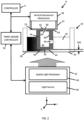
- FIG. 2 is a schematic block diagram depicting an exemplary embodiment of the print engine 8.
- Print engine 8 includes a vessel 24 for containing photocurable resin 26 and having a lower portion 28 with a transparent sheet 30.
- a fixture 32 supports a three dimensional article of manufacture 34 that is being formed in photocurable resin 26.
- the three dimensional article of manufacture 34 has a lower face 36 in facing relation with the transparent sheet 30.
- a movement mechanism 38 is coupled to the fixture 32 and controls a height H(t) of the lower face 36 above the transparent sheet 30. Between the lower face 36 of the three dimensional article of manufacture 34 is a thin layer 40 of photocurable resin 26.
- a light engine 42 is disposed and arranged to project pixelated radiation up through the transparent sheet 30 to selectively illuminate a build plane 44 that is proximate to the lower face 36 of the three dimensional article of manufacture 34.
- Light engine 42 includes a light source 46 that illuminates a spatial light modulator 48.
- the spatial light modulator 48 includes an array of pixel elements that process "raw” or unprocessed light from the light source 46 to selectively illuminate pixel elements of build plane 44.
- Print engine 8 includes print engine controller 50 which controls the vertical movement mechanism 38 and the light engine 48 when print engine 8 is fabricating the three dimensional article of manufacture 34.
- the print engine controller 50 is under control of the work cell controller 6.
- Fixture 32 includes a lower portion 52 defining a lower face 54 upon which the three dimensional article of manufacture 34 is formed. Formed into fixture 32 is a first fluid conduit 56 that defines an opening 58 on lower face 54. First fluid conduit 56 is illustrated as a vertical conduit through the lower portion 52 of fixture 32. In an alternative embodiment the first fluid conduit 56 may take another route through a fixture 32 but would still couple to opening 58 on lower face 54.
- the three dimensional article of manufacture 34 has an inside surface 60 that defines an internal cavity 62.
- the three dimensional article of manufacture 34 also defines a inlet port 64 that is formed in alignment and fluidically coupled to the opening 58 on lower face 54. Thus the inlet port 64 couples the fluid conduit 56 to the internal cavity 62.
- the three dimensional article of manufacture 34 defines an exit port 66 that couples the internal cavity 62 to an external portion of the three dimensional article of manufacture 34.
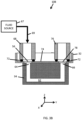
- FIG. 3A is a schematic block diagram depicting a first embodiment of a fluid processing station 10A that is engaged with a fixture 32 which is supporting a three dimensional article of manufacture 34.
- Fluid processing station 10A includes a fluid source 67 that is fluidically coupled to a fluid injector port 68 and a containment receptacle 70.
- a tube 69 couples the fluid source 67 to the fluid injector port 68.
- the fluid injector port 68 is sealingly engaged with the first fluid conduit 56.
- the fluid processing station 10A is therefore configured to inject fluid from the fluid source 67, through fluid injector 68, through first fluid conduit 56, through inlet port 64, and into the internal cavity 62.
- the injected fluid along with displaced fluid can exit through exit port 66 and into the containment receptacle 70.
- the fluid injector port 68 includes an annular sealing member 72 for providing a face seal between the fluid injector port 68 and an upper surface 74 of the fixture 32.
- the sealing member 72 is an o-ring.
- FIG. 3B is a schematic block diagram depicting a second embodiment of a fluid processing station 10B engaged with fixture 32 supporting a three dimensional article of manufacture 34.
- Fluid processing station 10B includes a fluid source 67 that is fluidically coupled to fluid injector port 68.
- Fluid processing station 10B also includes a fluid receiver port 76.
- the fluid injector port is 68 is sealingly engaged with the first fluid conduit 56.
- the fluid processing station 10B is therefore configured to inject fluid from the fluid source 67, through fluid injector 68, through first fluid conduit 56, through inlet port 64, and into the internal cavity 62.
- the fixture 32 includes a second fluid conduit 78 that is aligned with the fluid exit port 66 of the three dimensional article of manufacture 34.
- the fluid receiver port 76 is sealingly engaged with the second fluid conduit 78.
- the injected fluid can exit through the exit port 66, through the second fluid conduit 78, and into the fluid receiver port 76.
- both the fluid injector port 68 and the fluid receiver port 76 include a sealing member 72 for sealing to the upper surface 74 of the fixture.
- the inside surface 60 can also have a geometry or manifold that facilitates an optimized fluid flow of the injected fluid through the three dimensional article of manufacture 34.
- a geometry or manifold that facilitates an optimized fluid flow of the injected fluid through the three dimensional article of manufacture 34.
- Such an optimized geometry can be utilized for various embodiments including those depicted in FIGS. 3A and FIG. 3B .
- FIG. 4 is a schematic block diagram depicting cure station 12 that utilizes the aligned combination of the conduit 56 and the inlet port 64 to facilitate curing of the three dimensional article of manufacture 34.
- Cure station 12 includes a cure light source 71 to illuminate the inside surface 60 of the three dimensional article of manufacture 34.
- a light pipe 73 is utilized to transmit the light between the light source and the internal cavity 62. The light pipe passes from the light source 71, through the conduit 56, through the inlet port 64, and into the internal cavity 62.
- the light pipe 73 has an upper portion that utilizes total internal reflection to transmit the light from the light source 71 to the conduit 56.
- the light pipe 73 can have a lower portion 77 that has features that cause light emission such as utilizing controlled facets or a material that "frustrates" the total internal reflection causing the light pipe 73 to emit light along the lower portion 77.
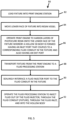
- FIG. 5 is a flowchart depicting an exemplary operational process 80 for the printing system 2.
- Process 80 does not include all steps but those that emphasize automation related to the fluid processing stations 10. The steps of process 80 occur under the control of work cell controller 6 as it controls the print engines 8, fluid processing stations 10, and transport mechanism 16.
- a fixture 32 is loaded into a print engine 8.
- the transport mechanism 16 grasps and lifts a new fixture 32 from a stack and then inserts it into print engine 8.
- the fixture 32 has a first fluid conduit 56 that defines an opening 58 at a lower surface 54 of fixture 32.
- the fixture 32 can include a second fluid conduit 78 as in FIG. 3B .
- step 84 the vertical movement mechanism 38 moves the fixture 32 downward until the lower face 54 of fixture 16 is immersed in photocurable resin 26 and in facing relation with the transparent sheet 30.
- the print engine 8 operates the light engine 42 and the vertical movement mechanism 38 to form the three dimensional article of manufacture 34 onto and extending downward from the lower face 54 of fixture 32.
- the three dimensional article of manufacture 34 is hollow and therefore has an inside surface 60 defining an internal cavity 62.
- the three dimensional article of manufacture 34 includes an inlet port 64 that is aligned with the opening 58 and couples the opening 58 to the internal cavity 62.
- the three dimensional article of manufacture 34 also includes an exit port 66.
- step 86 includes the following sub-steps under control of print engine controller 58: (a) The light engine selectively illuminates build plane 44 with pixelated light to selectively cure and harden a layer of photocurable resin 26 onto the lower face 54 of fixture 32. This is the first layer of the three dimensional article of manufacture 34; (b) The vertical movement mechanism repositions the lower face 36 of the three dimensional article of manufacture 34; (c) Step a is repeated except to harden a new layer of photocurable resin 26 onto the lower face 36 of the three dimensional article of manufacture 34. Steps b and c are repeated until the three dimensional article of manufacture 34 is fully formed.
- the motion in step b can include up and down motion and may vary in magnitude during step 86.
- the transport mechanism 16 removes the fixture 32 from the print engine 8 and places the fixture 32 into a fluid processing station 10.
- the fluid injector port 68 of the fluid processing station 10 sealingly engages with the first fluid conduit 56 of fixture 32.
- the fluid processing station 10 injects fluid through the fluid injector port 68.
- the injected fluid flows (1) out of the fluid injector port 68, (2) through the first fluid conduit 56, (3) through the inlet port 64, and (4) into the internal cavity 62.
- Fluid also flows out of the exit port 66, the exiting fluid can include displaced fluid and some of the injected fluid.
- FIG. 6 is a flowchart depicting a method 94 of operating the printing system 2 utilizing all of the stations illustrated in FIG. 2 .
- fixture 32 is loaded into print engine station 8.
- Step 96 may be similar to step 82 of FIG. 5 .
- step 98 the print engine 8 is operated to for a three dimensional article of manufacture 34.
- Step 98 may be similar to steps 84 and 86 of FIG. 5 .
- step 100 the fixture 32 is transported to a wash station 18 which is then operated to clean the three dimensional article of manufacture 34.
- Step 100 is similar to steps 88, 90, and 92 in which the fluid source 67 is a solvent for flushing out uncured photocurable resin 26.
- step 102 the fixture 32 is transported to a dry station 20 which is then operated to dry the three dimensional article of manufacture 34.
- Step 102 is similar to steps 88, 90, and 92 in which the fluid source 67 is a pressurized source of gas for driving out and/or drying residual solvent.
- step 104 the fixture is transported to a material injection station 22 which is then operated to fill the internal cavity 62 of the three dimensional article of manufacture 34.
- Step 104 is similar to steps 88, 90, and 92 in which the fluid source 67 is a liquid and/or fluidized build material.
- the three dimensional article of manufacture 34 acts as a mold for the injected build material.
- the fixture is transported to a cure station 12 which is then operated to cure the three dimensional article of manufacture 34 and/or material that has been injected within.
- the fixture is then transported to the inspection station 14 which is then operated to inspect for critical dimensions and/or defects of the three dimensional article of manufacture 34 and/or injected material.
- process sequence 94 Other embodiments of the process sequence 94 are possible. Certain steps can be skipped or reordered. One embodiment includes all steps except for step 104. Another embodiment includes all steps except for step 106. Yet other embodiments may eliminate steps 106 and 108 or eliminate step 108. In some embodiments the cure step 106 may take place before and after step 104. Thus a number of different subsets and sequences are possible with respect to the steps of method 94.
Landscapes
- Engineering & Computer Science (AREA)
- Chemical & Material Sciences (AREA)
- Materials Engineering (AREA)
- Manufacturing & Machinery (AREA)
- Physics & Mathematics (AREA)
- Optics & Photonics (AREA)
- Mechanical Engineering (AREA)
- Robotics (AREA)
Description
- This non-provisional patent application claims priority to
U.S. Provisional Application Serial Number 62/457,474, Entitled "INTEGRATION OF THREE DIMENSIONAL PRINTING PROCESSES" by Ben Wynne et al., filed on February 10, 2017 - The present disclosure concerns a three dimensional printing system for the digital fabrication of three dimensional articles. More particularly the present disclosure concerns an effective way of integrating print engines and post-processes into a manufacturing work cell.
- Three dimensional print engines are in widespread use. Examples of three dimensional print technologies includes stereolithography, selective laser sintering, and fused deposition modeling to name a few. Stereolithography-based printers utilize a controllable light engine to selectively harden or solidify a liquid photocurable resin in a layerwise manner until a three dimensional article of manufacture is formed. In some embodiments the light engine includes a light source that illuminates a spatial light modulator.
- Document
WO2015/142546 A1 discloses a method of forming a three-dimensional object carried out by: (a) providing a carrier and an optically transparent member having a build surface, with the carrier and the build surface defining a build region therebetween; (b) filling the build region with a polymerizable liquid; (c) irradiating the build region with light through the optically transparent member to form a solid polymer from the polymerizable liquid; and (d) advancing the carrier away from the build surface to form the three-dimensional object from the solid polymer; (e) wherein the carrier has at least one channel formed therein, the method further including supplying pressurized gas into the build region through the at least one channel during at least a portion of the filling, irradiating and/or advancing steps. - After a print engine completes a three dimensional article of manufacture there are post-processes to wash away unused photocurable resin, drying residual fluid, and curing. The post-processes can be very labor and time intensive. Because most three dimensional printing has been used for low volume prototyping, the post-processes have been acceptable.
- However, there is a desire to utilize stereolithography print engines for manufacturing. This requires automation of the printing and post-processes. The post-processes as they exist are not designed for automation. The post-processes can become even more challenging when fine geometries are involved. There is a need to find better solutions for integrating and automating all of the processes for three dimensional printing systems.
-
-
FIG. 1 is a schematic block diagram depicting an exemplary threedimensional printing system 2. -
FIG. 2 is a schematic diagram depicting an exemplary print engine. -
FIG. 3A is a schematic diagram depicting a first embodiment of a fluid processing station engaged with a fixture that is supporting a three dimensional article of manufacture. -
FIG. 3B is a schematic diagram depicting a second embodiment of a fluid processing station engaged with a fixture that is supporting a three dimensional article of manufacture. -
FIG. 4 is a schematic diagram depicting a cure station. -
FIG. 5 is a flowchart depicting an exemplary operational process for the printing system. -
FIG. 6 is a flowchart depicting an exemplary operational process for the printing system. - In a first aspect of the disclosure, according to
claim 1, a three dimensional printing system includes a three dimensional print engine, a fluid processing station, a fixture, a transport mechanism, and a controller. The three dimensional print engine includes a vessel for containing photocurable resin including a transparent sheet at a lower end, a light engine for transmitting pixelated light up through the transparent sheet into the photocurable resin, and a movement mechanism. The fluid processing station includes a fluid injector port coupled to a fluid source. - The fixture has a lower portion defining a lower face and a first fluid conduit coupled to the lower face. The controller is configured to: (a) Position the lower face of the fixture in facing relation with the transparent sheet. (b) Operate the three dimensional print engine including the light engine and the movement mechanism to form a three dimensional article of manufacture onto the lower face of the fixture, the three dimensional article of manufacture having an inside surface defining an internal cavity and an inlet port that couples the internal cavity to the first fluid conduit of the fixture, and an exit port that couples the internal cavity to an external portion of the three dimensional article of manufacture. (c) Operate the transport mechanism to transfer the fixture with the attached three dimensional article of manufacture to the fluid processing station. (d) Couple the fluid injector port of the fluid processing station to the first fluid conduit of the fixture. (e) Operate the fluid source to inject fluid out of the fluid injector port, through the first fluid conduit, through the inlet port, and to the internal cavity.
- In one implementation the light engine includes a light source that illuminates a spatial light modulator. The spatial light modulator processes light form the light source to provide an array of pixel elements projected onto a build plane. In one embodiment the spatial light modulator is an array of micromirrors that can be tilted between on states and off states.
- In another implementation the fluid processing station is a wash station. The fluid source contains a liquid cleaning solvent. Step (e) results in the cleaning solvent flushing uncured photocurable resin out the of the internal cavity of the three dimensional article of manufacture.
- In yet another implementation the fluid processing station is a drying station. The fluid source contains a pressurized gas. Step (e) results in the dry gas flushing resin or solvent out of the internal cavity of the three dimensional article of manufacture.
- In a further implementation the fluid processing station is a build material injection station. The fluid source contains build material. Step (e) results in the filling of the internal cavity with build material. In one embodiment the internal cavity functions as a removable mold for the build material.
- In a yet further implementation the fluid source contains an etchant. Step (e) includes etching the inside surface of the three dimensional article of manufacture.
- In another implementation the fluid source contains a coating agent. Step (e) includes coating the inside surface of the three dimensional article of manufacture with a material layer.
- In yet another implementation step (e) includes partially melting the inside surface. The fluid source can be heated and/or contain a solvent that can dissolve away a layer of material from the inside surface.
- In a further implementation the inside surface defines a fluid manifold that establishes an optimized flow regime of the injected fluid through the internal cavity.
- In a yet further implementation the exit port allows fluid to exit from the internal cavity while the injected fluid is entering the internal cavity. The exiting fluid can be one or more of a displaced fluid and the injected fluid and a mixture thereof. In a first embodiment the fluid processing station includes a receptacle for receiving the exiting fluid. In a second embodiment the fixture includes a second fluid conduit that is coupled to the exit port.
- In another implementation a cure station has an optical component for utilizing the first fluid conduit and the inlet port for transmitting radiation into the internal cavity to enhance radiation curing of the three dimensional article of manufacture. In one embodiment the optical component is a light pipe.
- In yet another implementation the controller includes a processor coupled to an information storage device. The information storage device includes a non-transient or non-volatile information storage device that stores instructions. The instructions, when executed, control portions of the three dimensional printing system such as a print engine, a fluid processing station, a cure station, or an inspection station. The controller can be integrated into one integrated circuit or it can reside on a plurality of devices. Such a plurality of devices can be co-located or can be distributed in various locations in the three dimensional printing system or even remotely from one another.
- In the disclosure mutually orthogonal axes X, Y, and Z are used. Axes X and Y are lateral axes and can be horizontal axes. Axis Z is can be a vertical axis. Generally speaking a direction of +Z is upward and -Z is downward. However, the axis Z may not be exactly aligned with a gravitational reference.
-
FIG. 1 is a schematic block diagram depicting an exemplary threedimensional printing system 2. Threedimensional printing system 2 includes awork cell 4 under control ofcontroller 6.Controller 6 controls stations (8, 10, 12, 14) within thework cell 4 and atransport 16 between the stations. In oneembodiment controller 6 is a "standalone"workstation 6 that can be operated by a technician. In anotherembodiment controller 6 is aserver 6 that is controllable remotely by other servers and/or client devices. In anexemplary embodiment controller 6 has both server and workstation capabilities. - The
work cell 4 includesprint engines 8,fluid processing stations 10,cure stations 12,inspection stations 14, and atransport mechanism 16. Theprint engines 8 are those that utilize a photocurable resin and can fabricate a three dimensional article of manufacture by the sequential curing and hardening of polymer layers of the resin. An exemplary print engine will be described with respect toFIG. 2 . - The
fluid processing stations 10 are configured to automatically inject fluid into and through a three dimensional article of manufacture in order to provide cleaning, drying, etching, coating, or material injection. In the exemplary embodiment thefluid processing stations 10 includewash stations 18,dry stations 20, andmaterial stations 22. Washstations 18 are for injecting a cleaning solvent to remove residual uncured resin from a three dimensional article of manufacture.Dry stations 20 are for injecting gas for removing and drying fluid such as the cleaning solvent.Material stations 22 are for injecting a body material into the three dimensional article of manufacture.Material stations 22 enable the three dimensional article of manufacture to be utilized as a mold and/or provide a composite three dimensional article of manufacture made of two different materials. - Additional
fluid processing stations 10 not illustrated can be part ofwork cell 4. Different fluid sources can be used such as chemical etchants, fluids that leave behind a coating, or fluids that partially melt the inside. Heated or chilled fluids can be utilized. - Cure
stations 12 provide radiation and/or thermal curing for the three dimensional article of manufacture.Inspection stations 14 can be programmed to inspect critical dimensions and features of the three dimensional article of manufacture.Transport mechanism 16 provides automated transport between thestations transport mechanism 16 may include a robotic gripping mechanism that has translation motion in three dimensions along X, Y, and Z. -
FIG. 2 is a schematic block diagram depicting an exemplary embodiment of theprint engine 8.Print engine 8 includes avessel 24 for containingphotocurable resin 26 and having alower portion 28 with atransparent sheet 30. Afixture 32 supports a three dimensional article ofmanufacture 34 that is being formed inphotocurable resin 26. The three dimensional article ofmanufacture 34 has alower face 36 in facing relation with thetransparent sheet 30. Amovement mechanism 38 is coupled to thefixture 32 and controls a height H(t) of thelower face 36 above thetransparent sheet 30. Between thelower face 36 of the three dimensional article ofmanufacture 34 is athin layer 40 ofphotocurable resin 26. - A
light engine 42 is disposed and arranged to project pixelated radiation up through thetransparent sheet 30 to selectively illuminate abuild plane 44 that is proximate to thelower face 36 of the three dimensional article ofmanufacture 34.Light engine 42 includes alight source 46 that illuminates a spatiallight modulator 48. The spatiallight modulator 48 includes an array of pixel elements that process "raw" or unprocessed light from thelight source 46 to selectively illuminate pixel elements ofbuild plane 44. -
Print engine 8 includesprint engine controller 50 which controls thevertical movement mechanism 38 and thelight engine 48 whenprint engine 8 is fabricating the three dimensional article ofmanufacture 34. Theprint engine controller 50 is under control of thework cell controller 6. -
Fixture 32 includes alower portion 52 defining alower face 54 upon which the three dimensional article ofmanufacture 34 is formed. Formed intofixture 32 is a firstfluid conduit 56 that defines anopening 58 onlower face 54. Firstfluid conduit 56 is illustrated as a vertical conduit through thelower portion 52 offixture 32. In an alternative embodiment the firstfluid conduit 56 may take another route through afixture 32 but would still couple to opening 58 onlower face 54. - The three dimensional article of
manufacture 34 has aninside surface 60 that defines aninternal cavity 62. The three dimensional article ofmanufacture 34 also defines ainlet port 64 that is formed in alignment and fluidically coupled to theopening 58 onlower face 54. Thus theinlet port 64 couples thefluid conduit 56 to theinternal cavity 62. The three dimensional article ofmanufacture 34 defines anexit port 66 that couples theinternal cavity 62 to an external portion of the three dimensional article ofmanufacture 34. -
FIG. 3A is a schematic block diagram depicting a first embodiment of afluid processing station 10A that is engaged with afixture 32 which is supporting a three dimensional article ofmanufacture 34.Fluid processing station 10A includes afluid source 67 that is fluidically coupled to afluid injector port 68 and acontainment receptacle 70. In one embodiment atube 69 couples thefluid source 67 to thefluid injector port 68. - The
fluid injector port 68 is sealingly engaged with the firstfluid conduit 56. Thefluid processing station 10A is therefore configured to inject fluid from thefluid source 67, throughfluid injector 68, through firstfluid conduit 56, throughinlet port 64, and into theinternal cavity 62. The injected fluid along with displaced fluid can exit throughexit port 66 and into thecontainment receptacle 70. - In the illustrated embodiment the
fluid injector port 68 includes anannular sealing member 72 for providing a face seal between thefluid injector port 68 and anupper surface 74 of thefixture 32. In one embodiment the sealingmember 72 is an o-ring. -
FIG. 3B is a schematic block diagram depicting a second embodiment of afluid processing station 10B engaged withfixture 32 supporting a three dimensional article ofmanufacture 34.Fluid processing station 10B includes afluid source 67 that is fluidically coupled tofluid injector port 68.Fluid processing station 10B also includes afluid receiver port 76. - Similar to
FIG. 3A , the fluid injector port is 68 is sealingly engaged with the firstfluid conduit 56. Thefluid processing station 10B is therefore configured to inject fluid from thefluid source 67, throughfluid injector 68, through firstfluid conduit 56, throughinlet port 64, and into theinternal cavity 62. - In this embodiment, the
fixture 32 includes a secondfluid conduit 78 that is aligned with thefluid exit port 66 of the three dimensional article ofmanufacture 34. Thefluid receiver port 76 is sealingly engaged with the secondfluid conduit 78. Thus, the injected fluid can exit through theexit port 66, through the secondfluid conduit 78, and into thefluid receiver port 76. In the illustrated embodiment both thefluid injector port 68 and thefluid receiver port 76 include a sealingmember 72 for sealing to theupper surface 74 of the fixture. - The
inside surface 60 can also have a geometry or manifold that facilitates an optimized fluid flow of the injected fluid through the three dimensional article ofmanufacture 34. Such an optimized geometry can be utilized for various embodiments including those depicted inFIGS. 3A andFIG. 3B . -
FIG. 4 is a schematic block diagram depictingcure station 12 that utilizes the aligned combination of theconduit 56 and theinlet port 64 to facilitate curing of the three dimensional article ofmanufacture 34.Cure station 12 includes acure light source 71 to illuminate theinside surface 60 of the three dimensional article ofmanufacture 34. In one embodiment alight pipe 73 is utilized to transmit the light between the light source and theinternal cavity 62. The light pipe passes from thelight source 71, through theconduit 56, through theinlet port 64, and into theinternal cavity 62. In one embodiment thelight pipe 73 has an upper portion that utilizes total internal reflection to transmit the light from thelight source 71 to theconduit 56. Thelight pipe 73 can have alower portion 77 that has features that cause light emission such as utilizing controlled facets or a material that "frustrates" the total internal reflection causing thelight pipe 73 to emit light along thelower portion 77. -
FIG. 5 is a flowchart depicting an exemplaryoperational process 80 for theprinting system 2.Process 80 does not include all steps but those that emphasize automation related to thefluid processing stations 10. The steps ofprocess 80 occur under the control ofwork cell controller 6 as it controls theprint engines 8,fluid processing stations 10, andtransport mechanism 16. - According to step 82, a
fixture 32 is loaded into aprint engine 8. In one embodiment thetransport mechanism 16 grasps and lifts anew fixture 32 from a stack and then inserts it intoprint engine 8. Thefixture 32 has a firstfluid conduit 56 that defines anopening 58 at alower surface 54 offixture 32. In some embodiments thefixture 32 can include a secondfluid conduit 78 as inFIG. 3B . - According to step 84, the
vertical movement mechanism 38 moves thefixture 32 downward until thelower face 54 offixture 16 is immersed inphotocurable resin 26 and in facing relation with thetransparent sheet 30. - According to step 86, the
print engine 8 operates thelight engine 42 and thevertical movement mechanism 38 to form the three dimensional article ofmanufacture 34 onto and extending downward from thelower face 54 offixture 32. The three dimensional article ofmanufacture 34 is hollow and therefore has aninside surface 60 defining aninternal cavity 62. The three dimensional article ofmanufacture 34 includes aninlet port 64 that is aligned with theopening 58 and couples theopening 58 to theinternal cavity 62. The three dimensional article ofmanufacture 34 also includes anexit port 66. - In one embodiment,
step 86 includes the following sub-steps under control of print engine controller 58: (a) The light engine selectively illuminatesbuild plane 44 with pixelated light to selectively cure and harden a layer ofphotocurable resin 26 onto thelower face 54 offixture 32. This is the first layer of the three dimensional article ofmanufacture 34; (b) The vertical movement mechanism repositions thelower face 36 of the three dimensional article ofmanufacture 34; (c) Step a is repeated except to harden a new layer ofphotocurable resin 26 onto thelower face 36 of the three dimensional article ofmanufacture 34. Steps b and c are repeated until the three dimensional article ofmanufacture 34 is fully formed. The motion in step b can include up and down motion and may vary in magnitude duringstep 86. - According to step 88, the
transport mechanism 16 removes thefixture 32 from theprint engine 8 and places thefixture 32 into afluid processing station 10. According to step 90, thefluid injector port 68 of thefluid processing station 10 sealingly engages with the firstfluid conduit 56 offixture 32. - According to step 92, the
fluid processing station 10 injects fluid through thefluid injector port 68. The injected fluid flows (1) out of thefluid injector port 68, (2) through the firstfluid conduit 56, (3) through theinlet port 64, and (4) into theinternal cavity 62. Fluid also flows out of theexit port 66, the exiting fluid can include displaced fluid and some of the injected fluid. -
FIG. 6 is a flowchart depicting amethod 94 of operating theprinting system 2 utilizing all of the stations illustrated inFIG. 2 . According to step 96fixture 32 is loaded intoprint engine station 8.Step 96 may be similar to step 82 ofFIG. 5 . According to step 98, theprint engine 8 is operated to for a three dimensional article ofmanufacture 34.Step 98 may be similar tosteps FIG. 5 . - According to step 100, the
fixture 32 is transported to awash station 18 which is then operated to clean the three dimensional article ofmanufacture 34. Step 100 is similar tosteps fluid source 67 is a solvent for flushing out uncuredphotocurable resin 26. - According to step 102, the
fixture 32 is transported to adry station 20 which is then operated to dry the three dimensional article ofmanufacture 34. Step 102 is similar tosteps fluid source 67 is a pressurized source of gas for driving out and/or drying residual solvent. - According to step 104, the fixture is transported to a
material injection station 22 which is then operated to fill theinternal cavity 62 of the three dimensional article ofmanufacture 34. Step 104 is similar tosteps fluid source 67 is a liquid and/or fluidized build material. In an exemplary embodiment the three dimensional article ofmanufacture 34 acts as a mold for the injected build material. - According to step 106, the fixture is transported to a
cure station 12 which is then operated to cure the three dimensional article ofmanufacture 34 and/or material that has been injected within. According to step 108, the fixture is then transported to theinspection station 14 which is then operated to inspect for critical dimensions and/or defects of the three dimensional article ofmanufacture 34 and/or injected material. - Other embodiments of the
process sequence 94 are possible. Certain steps can be skipped or reordered. One embodiment includes all steps except forstep 104. Another embodiment includes all steps except forstep 106. Yet other embodiments may eliminatesteps step 108. In some embodiments thecure step 106 may take place before and afterstep 104. Thus a number of different subsets and sequences are possible with respect to the steps ofmethod 94. - The specific embodiments and applications thereof described above are for illustrative purposes only and do not preclude modifications and variations encompassed by the scope of the following claims.
Claims (14)
- A three dimensional printing system (2) comprising:a three dimensional print engine (8) including:a vessel (24) for containing photocurable resin (26) including a transparent sheet (30) at a lower end;a light engine (42) for transmitting pixelated light up through the transparent sheet (30) into the photocurable resin (26);a movement mechanism (38);a fluid processing station (10) including a fluid injector port (68) coupled to a fluid source (67);a fixture (32) having a lower portion (52) defining a lower face (54) and a first fluid conduit (56) coupled to the lower face (54);a transport mechanism (16); anda controller (58) configured to:(a) position the lower face (54) of the fixture (32) in facing relation with the transparent sheet (30);(b) operate the three dimensional print engine (8) including the light engine (42) and the movement mechanism (38) to form a three dimensional article of manufacture (34) onto the lower face (54) of the fixture (32), the three dimensional article of manufacture (34) having an inside surface (60) that defines an internal cavity (62), an inlet port (64) that couples the internal cavity (62) to the first fluid conduit (56) of the fixture (32), and an exit port (66) that couples the internal cavity (62) to an external portion of the three dimensional article of manufacture (34);(c) operate the transport mechanism (16) to transfer the fixture (32) with the attached three dimensional article of manufacture (34) to the fluid processing station (10);(d) couple the fluid injector port (68) of the fluid processing station (10) to the first fluid conduit (56) of the fixture (32);(e) operate the fluid source (67) to inject fluid out of the fluid injector port (68), through the first fluid conduit (56) and the inlet port (64), and to the internal cavity (62).
- The three dimensional printing system (2) of claim 1 wherein the injected fluid is one of a liquid cleaning solvent, a gas for drying, a build material, an etchant, a liquid containing a coating agent for coating an inside surface, and a liquid for partially melting an inside surface.
- The three dimensional printing system (2) of claim 1 wherein the exit port (66) coupled to the internal cavity (62) allows fluid to exit from the internal cavity (62) concurrently with the fluid being injected into the internal cavity (62).
- The three dimensional printing system (2) of claim 3 wherein the fluid processing station includes a receptacle (70) for receiving the fluid that is exiting the internal cavity (62) through the exit port (66).
- The three dimensional printing system (2) of claim 3 wherein the fixture (32) includes a second fluid conduit (78) that is coupled to the exit port (66).
- The three dimensional printing system (2) of claim 1 wherein the fluid processing station (10) is a wash station (18) and the injected fluid is a solvent for flushing uncured photocurable resin from the internal cavity (62).
- The three dimensional printing system (2) of claim 6 further comprising a drying station including a gas injector coupled to a gas pressure source, the controller further configured to:(f) operate the transport mechanism to transfer the fixture from the wash station to the drying station;(g) couple the gas injector to the first fluid conduit; and(h) operate the gas pressure source to flush gas through the internal cavity to remove residual solvent from the internal cavity.
- A method of manufacturing a three dimensional article using a three dimensional printing system having a vessel containing photocurable resin, a light engine, a movement mechanism, a fluid processing station with an injector port coupled to a fluid source, a fixture having a lower portion and a first fluid conduit coupled to the lower face, and a transport mechanism comprising:(a) positioning the lower face of the fixture within the resin;(b) operating the light engine and the movement mechanism to form a three dimensional article of manufacture onto the lower face of the fixture, the three dimensional article of manufacture having an inside surface that defines an internal cavity, an inlet port that couples the internal cavity to the first fluid conduit of the fixture and an exit port that couples the internal cavity to an external portion of the three dimensional article of manufacture;(c) operating the transport mechanism to transfer the fixture with the attached three dimensional article of manufacture to the fluid processing station;(d) coupling the fluid injector port of the fluid processing station to the first fluid conduit of the fixture;(e) operating the fluid source to inject fluid out of the fluid injector port, through the first fluid conduit and the inlet port, and to the internal cavity.
- The method of claim 8 wherein the injected fluid is one of a liquid cleaning solvent, a gas for drying, a build material, an etchant, a liquid containing a coating agent for coating an inside surface, and a liquid for partially melting an inside surface.
- The method of claim 8 wherein the exit port coupled to the internal cavity allows fluid to exit from the internal cavity concurrently with the fluid being injected into the internal cavity.
- The method of claim 10 wherein the fluid processing station includes a receptacle for receiving the fluid that is exiting the internal cavity through the exit port.
- The method of claim 10 wherein the fixture includes a second fluid conduit that is coupled to the exit port.
- The method of claim 8 wherein the fluid processing station is a wash station and the injected fluid is a solvent for flushing uncured photocurable resin from the internal cavity.
- The method of claim 13 further comprising the steps of:operating the transport mechanism to transfer the fixture from the wash station to the drying station which includes a gas injector coupled to a gas pressure source;coupling the gas injector to the first fluid conduit; andoperating the gas pressure source to flush gas through the internal cavity to remove residual solvent from the internal cavity.
Applications Claiming Priority (2)
| Application Number | Priority Date | Filing Date | Title |
|---|---|---|---|
| US201762457474P | 2017-02-10 | 2017-02-10 | |
| PCT/US2017/060634 WO2018147914A1 (en) | 2017-02-10 | 2017-11-08 | Integration of three dimensional printing processes |
Publications (2)
| Publication Number | Publication Date |
|---|---|
| EP3580058A1 EP3580058A1 (en) | 2019-12-18 |
| EP3580058B1 true EP3580058B1 (en) | 2024-07-31 |
Family
ID=60409466
Family Applications (1)
| Application Number | Title | Priority Date | Filing Date |
|---|---|---|---|
| EP17801265.4A Active EP3580058B1 (en) | 2017-02-10 | 2017-11-08 | Integration of three dimensional printing processes |
Country Status (4)
| Country | Link |
|---|---|
| US (2) | US10926462B2 (en) |
| EP (1) | EP3580058B1 (en) |
| JP (1) | JP6883658B2 (en) |
| WO (1) | WO2018147914A1 (en) |
Families Citing this family (4)
| Publication number | Priority date | Publication date | Assignee | Title |
|---|---|---|---|---|
| US10668709B2 (en) * | 2014-08-12 | 2020-06-02 | Carbon, Inc. | Three-dimensional printing using carriers with release mechanisms |
| US20190210151A1 (en) * | 2018-01-08 | 2019-07-11 | General Electric Company | Systems and methods for additive manufacturing using pressurized consolidation devices |
| DE102019102359A1 (en) * | 2019-01-30 | 2020-07-30 | Dekema Dental-Keramiköfen GmbH | Process for producing a component using a three-dimensional printing process |
| JP7558102B2 (en) | 2021-03-25 | 2024-09-30 | Solize株式会社 | Method for forming workpiece and workpiece |
Family Cites Families (13)
| Publication number | Priority date | Publication date | Assignee | Title |
|---|---|---|---|---|
| JPH0760843A (en) * | 1993-08-26 | 1995-03-07 | Olympus Optical Co Ltd | Method for manufacturing three-dimensional structure |
| JP2000330468A (en) * | 1999-05-18 | 2000-11-30 | Hitachi Ltd | Model making method and equipment |
| EP2671706A1 (en) * | 2012-06-04 | 2013-12-11 | Ivoclar Vivadent AG | Method for creating an object |
| EP3187938A1 (en) | 2013-02-12 | 2017-07-05 | CARBON3D, Inc. | Method and apparatus for three-dimensional fabrication with feed through carrier |
| GB2513571A (en) * | 2013-04-29 | 2014-11-05 | Quill Internat Group Ltd | A method of washing support material from 3D-printed articles and a washing machine therefor |
| TW201522017A (en) * | 2013-12-13 | 2015-06-16 | 三緯國際立體列印科技股份有限公司 | Three dimensional printing apparatus |
| US10232605B2 (en) * | 2014-03-21 | 2019-03-19 | Carbon, Inc. | Method for three-dimensional fabrication with gas injection through carrier |
| US20150336233A1 (en) * | 2014-05-23 | 2015-11-26 | United Technologies Corporation | Conditioning one or more internal surfaces of an object |
| WO2016149151A1 (en) * | 2015-03-13 | 2016-09-22 | Carbon3D, Inc. | Three-dimensional printing with concurrent delivery of different polymerizable liquids |
| US10071546B2 (en) * | 2015-06-05 | 2018-09-11 | Collider, Inc. | Apparatus and method for hybrid manufacturing |
| US10765975B2 (en) * | 2016-07-01 | 2020-09-08 | Caterpillar Inc. | Filter element and method of manufacturing a filter element |
| DE102017200773A1 (en) * | 2017-01-18 | 2018-07-19 | Eos Gmbh Electro Optical Systems | Process for aftertreatment and aftertreatment system |
| EP3676003A1 (en) * | 2017-08-30 | 2020-07-08 | The Charles Stark Draper Laboratory Inc. | Systems and methods for fabricating microfluidic devices |
-
2017
- 2017-11-08 WO PCT/US2017/060634 patent/WO2018147914A1/en not_active Ceased
- 2017-11-08 JP JP2019540369A patent/JP6883658B2/en active Active
- 2017-11-08 EP EP17801265.4A patent/EP3580058B1/en active Active
- 2017-11-08 US US15/807,170 patent/US10926462B2/en active Active
-
2021
- 2021-01-22 US US17/155,140 patent/US11446866B2/en active Active
Also Published As
| Publication number | Publication date |
|---|---|
| WO2018147914A1 (en) | 2018-08-16 |
| US20210138728A1 (en) | 2021-05-13 |
| JP6883658B2 (en) | 2021-06-09 |
| US10926462B2 (en) | 2021-02-23 |
| US20180229432A1 (en) | 2018-08-16 |
| EP3580058A1 (en) | 2019-12-18 |
| JP2020506085A (en) | 2020-02-27 |
| US11446866B2 (en) | 2022-09-20 |
Similar Documents
| Publication | Publication Date | Title |
|---|---|---|
| US11446866B2 (en) | Three dimensional printing on a fixture and rinsing channels through fixture conduits | |
| US12370728B2 (en) | Sacrificial additively manufactured molds for use in injection molding processes | |
| US11254031B2 (en) | Additive manufacturing device and system for manufacturing a sacrificial mould for creating an object | |
| US20190126536A1 (en) | Cartridge vat-based additive manufacturing apparatus and method | |
| US20150165695A1 (en) | Three dimensional printing apparatus | |
| US20130295212A1 (en) | Digital mask-image-projection-based additive manufacturing that applies shearing force to detach each added layer | |
| US20190126535A1 (en) | Cartridge plate-based additive manufacturing apparatus and method | |
| EP4116066B1 (en) | Additive manufacturing method for functionally graded material | |
| CN111247470A (en) | Solid Freeform Fabrication Using In Situ Implantation and Imaging | |
| JP2020506085A5 (en) | ||
| US20180207885A1 (en) | Three dimensional printing mechanism and method for printing a three dimensional object | |
| JP6025079B2 (en) | Imprint apparatus and control method thereof | |
| KR20200078737A (en) | Apparatus for cleaning mask member and system for cleaning mask member | |
| US11173512B2 (en) | Cleaning fixtures and methods of cleaning components using cleaning fixtures | |
| CN112823313B (en) | Method and system for manufacturing three-dimensional objects | |
| EP3814118B1 (en) | A quick-change end effector | |
| WO2026027453A1 (en) | Device and method for printing paste and liquid material | |
| CN113165279A (en) | Molding apparatus and method of producing molded body | |
| KR100226015B1 (en) | Apparatus and method for rapid prototyping using photopolymer droplets | |
| KR20200093992A (en) | 3D Printer Vat | |
| KR20190045839A (en) | Imprint apparatus, and method of manufacturing article | |
| CN110315749A (en) | Facility comprising at least one apparatus for additively manufacturing three-dimensional objects |
Legal Events
| Date | Code | Title | Description |
|---|---|---|---|
| STAA | Information on the status of an ep patent application or granted ep patent |
Free format text: STATUS: UNKNOWN |
|
| STAA | Information on the status of an ep patent application or granted ep patent |
Free format text: STATUS: THE INTERNATIONAL PUBLICATION HAS BEEN MADE |
|
| PUAI | Public reference made under article 153(3) epc to a published international application that has entered the european phase |
Free format text: ORIGINAL CODE: 0009012 |
|
| STAA | Information on the status of an ep patent application or granted ep patent |
Free format text: STATUS: REQUEST FOR EXAMINATION WAS MADE |
|
| 17P | Request for examination filed |
Effective date: 20190729 |
|
| AK | Designated contracting states |
Kind code of ref document: A1 Designated state(s): AL AT BE BG CH CY CZ DE DK EE ES FI FR GB GR HR HU IE IS IT LI LT LU LV MC MK MT NL NO PL PT RO RS SE SI SK SM TR |
|
| AX | Request for extension of the european patent |
Extension state: BA ME |
|
| DAV | Request for validation of the european patent (deleted) | ||
| DAX | Request for extension of the european patent (deleted) | ||
| STAA | Information on the status of an ep patent application or granted ep patent |
Free format text: STATUS: EXAMINATION IS IN PROGRESS |
|
| 17Q | First examination report despatched |
Effective date: 20211118 |
|
| GRAP | Despatch of communication of intention to grant a patent |
Free format text: ORIGINAL CODE: EPIDOSNIGR1 |
|
| STAA | Information on the status of an ep patent application or granted ep patent |
Free format text: STATUS: GRANT OF PATENT IS INTENDED |
|
| INTG | Intention to grant announced |
Effective date: 20240410 |
|
| P01 | Opt-out of the competence of the unified patent court (upc) registered |
Effective date: 20240418 |
|
| GRAS | Grant fee paid |
Free format text: ORIGINAL CODE: EPIDOSNIGR3 |
|
| GRAA | (expected) grant |
Free format text: ORIGINAL CODE: 0009210 |
|
| STAA | Information on the status of an ep patent application or granted ep patent |
Free format text: STATUS: THE PATENT HAS BEEN GRANTED |
|
| AK | Designated contracting states |
Kind code of ref document: B1 Designated state(s): AL AT BE BG CH CY CZ DE DK EE ES FI FR GB GR HR HU IE IS IT LI LT LU LV MC MK MT NL NO PL PT RO RS SE SI SK SM TR |
|
| REG | Reference to a national code |
Ref country code: CH Ref legal event code: EP Ref country code: GB Ref legal event code: FG4D |
|
| REG | Reference to a national code |
Ref country code: DE Ref legal event code: R096 Ref document number: 602017083719 Country of ref document: DE |
|
| REG | Reference to a national code |
Ref country code: IE Ref legal event code: FG4D |
|
| REG | Reference to a national code |
Ref country code: LT Ref legal event code: MG9D |
|
| REG | Reference to a national code |
Ref country code: NL Ref legal event code: MP Effective date: 20240731 |
|
| PG25 | Lapsed in a contracting state [announced via postgrant information from national office to epo] |
Ref country code: PT Free format text: LAPSE BECAUSE OF FAILURE TO SUBMIT A TRANSLATION OF THE DESCRIPTION OR TO PAY THE FEE WITHIN THE PRESCRIBED TIME-LIMIT Effective date: 20241202 |
|
| REG | Reference to a national code |
Ref country code: AT Ref legal event code: MK05 Ref document number: 1708115 Country of ref document: AT Kind code of ref document: T Effective date: 20240731 |
|
| PG25 | Lapsed in a contracting state [announced via postgrant information from national office to epo] |
Ref country code: PT Free format text: LAPSE BECAUSE OF FAILURE TO SUBMIT A TRANSLATION OF THE DESCRIPTION OR TO PAY THE FEE WITHIN THE PRESCRIBED TIME-LIMIT Effective date: 20241202 |
|
| PG25 | Lapsed in a contracting state [announced via postgrant information from national office to epo] |
Ref country code: NO Free format text: LAPSE BECAUSE OF FAILURE TO SUBMIT A TRANSLATION OF THE DESCRIPTION OR TO PAY THE FEE WITHIN THE PRESCRIBED TIME-LIMIT Effective date: 20241031 |
|
| PG25 | Lapsed in a contracting state [announced via postgrant information from national office to epo] |
Ref country code: NL Free format text: LAPSE BECAUSE OF FAILURE TO SUBMIT A TRANSLATION OF THE DESCRIPTION OR TO PAY THE FEE WITHIN THE PRESCRIBED TIME-LIMIT Effective date: 20240731 Ref country code: PL Free format text: LAPSE BECAUSE OF FAILURE TO SUBMIT A TRANSLATION OF THE DESCRIPTION OR TO PAY THE FEE WITHIN THE PRESCRIBED TIME-LIMIT Effective date: 20240731 Ref country code: GR Free format text: LAPSE BECAUSE OF FAILURE TO SUBMIT A TRANSLATION OF THE DESCRIPTION OR TO PAY THE FEE WITHIN THE PRESCRIBED TIME-LIMIT Effective date: 20241101 Ref country code: FI Free format text: LAPSE BECAUSE OF FAILURE TO SUBMIT A TRANSLATION OF THE DESCRIPTION OR TO PAY THE FEE WITHIN THE PRESCRIBED TIME-LIMIT Effective date: 20240731 |
|
| PG25 | Lapsed in a contracting state [announced via postgrant information from national office to epo] |
Ref country code: BG Free format text: LAPSE BECAUSE OF FAILURE TO SUBMIT A TRANSLATION OF THE DESCRIPTION OR TO PAY THE FEE WITHIN THE PRESCRIBED TIME-LIMIT Effective date: 20240731 |
|
| PG25 | Lapsed in a contracting state [announced via postgrant information from national office to epo] |
Ref country code: LV Free format text: LAPSE BECAUSE OF FAILURE TO SUBMIT A TRANSLATION OF THE DESCRIPTION OR TO PAY THE FEE WITHIN THE PRESCRIBED TIME-LIMIT Effective date: 20240731 |
|
| PG25 | Lapsed in a contracting state [announced via postgrant information from national office to epo] |
Ref country code: IS Free format text: LAPSE BECAUSE OF FAILURE TO SUBMIT A TRANSLATION OF THE DESCRIPTION OR TO PAY THE FEE WITHIN THE PRESCRIBED TIME-LIMIT Effective date: 20241130 Ref country code: AT Free format text: LAPSE BECAUSE OF FAILURE TO SUBMIT A TRANSLATION OF THE DESCRIPTION OR TO PAY THE FEE WITHIN THE PRESCRIBED TIME-LIMIT Effective date: 20240731 |
|
| PG25 | Lapsed in a contracting state [announced via postgrant information from national office to epo] |
Ref country code: HR Free format text: LAPSE BECAUSE OF FAILURE TO SUBMIT A TRANSLATION OF THE DESCRIPTION OR TO PAY THE FEE WITHIN THE PRESCRIBED TIME-LIMIT Effective date: 20240731 |
|
| PG25 | Lapsed in a contracting state [announced via postgrant information from national office to epo] |
Ref country code: RS Free format text: LAPSE BECAUSE OF FAILURE TO SUBMIT A TRANSLATION OF THE DESCRIPTION OR TO PAY THE FEE WITHIN THE PRESCRIBED TIME-LIMIT Effective date: 20241031 Ref country code: ES Free format text: LAPSE BECAUSE OF FAILURE TO SUBMIT A TRANSLATION OF THE DESCRIPTION OR TO PAY THE FEE WITHIN THE PRESCRIBED TIME-LIMIT Effective date: 20240731 |
|
| PG25 | Lapsed in a contracting state [announced via postgrant information from national office to epo] |
Ref country code: RS Free format text: LAPSE BECAUSE OF FAILURE TO SUBMIT A TRANSLATION OF THE DESCRIPTION OR TO PAY THE FEE WITHIN THE PRESCRIBED TIME-LIMIT Effective date: 20241031 Ref country code: PL Free format text: LAPSE BECAUSE OF FAILURE TO SUBMIT A TRANSLATION OF THE DESCRIPTION OR TO PAY THE FEE WITHIN THE PRESCRIBED TIME-LIMIT Effective date: 20240731 Ref country code: NO Free format text: LAPSE BECAUSE OF FAILURE TO SUBMIT A TRANSLATION OF THE DESCRIPTION OR TO PAY THE FEE WITHIN THE PRESCRIBED TIME-LIMIT Effective date: 20241031 Ref country code: NL Free format text: LAPSE BECAUSE OF FAILURE TO SUBMIT A TRANSLATION OF THE DESCRIPTION OR TO PAY THE FEE WITHIN THE PRESCRIBED TIME-LIMIT Effective date: 20240731 Ref country code: LV Free format text: LAPSE BECAUSE OF FAILURE TO SUBMIT A TRANSLATION OF THE DESCRIPTION OR TO PAY THE FEE WITHIN THE PRESCRIBED TIME-LIMIT Effective date: 20240731 Ref country code: IS Free format text: LAPSE BECAUSE OF FAILURE TO SUBMIT A TRANSLATION OF THE DESCRIPTION OR TO PAY THE FEE WITHIN THE PRESCRIBED TIME-LIMIT Effective date: 20241130 Ref country code: HR Free format text: LAPSE BECAUSE OF FAILURE TO SUBMIT A TRANSLATION OF THE DESCRIPTION OR TO PAY THE FEE WITHIN THE PRESCRIBED TIME-LIMIT Effective date: 20240731 Ref country code: GR Free format text: LAPSE BECAUSE OF FAILURE TO SUBMIT A TRANSLATION OF THE DESCRIPTION OR TO PAY THE FEE WITHIN THE PRESCRIBED TIME-LIMIT Effective date: 20241101 Ref country code: FI Free format text: LAPSE BECAUSE OF FAILURE TO SUBMIT A TRANSLATION OF THE DESCRIPTION OR TO PAY THE FEE WITHIN THE PRESCRIBED TIME-LIMIT Effective date: 20240731 Ref country code: ES Free format text: LAPSE BECAUSE OF FAILURE TO SUBMIT A TRANSLATION OF THE DESCRIPTION OR TO PAY THE FEE WITHIN THE PRESCRIBED TIME-LIMIT Effective date: 20240731 Ref country code: BG Free format text: LAPSE BECAUSE OF FAILURE TO SUBMIT A TRANSLATION OF THE DESCRIPTION OR TO PAY THE FEE WITHIN THE PRESCRIBED TIME-LIMIT Effective date: 20240731 Ref country code: AT Free format text: LAPSE BECAUSE OF FAILURE TO SUBMIT A TRANSLATION OF THE DESCRIPTION OR TO PAY THE FEE WITHIN THE PRESCRIBED TIME-LIMIT Effective date: 20240731 |
|
| PG25 | Lapsed in a contracting state [announced via postgrant information from national office to epo] |
Ref country code: SM Free format text: LAPSE BECAUSE OF FAILURE TO SUBMIT A TRANSLATION OF THE DESCRIPTION OR TO PAY THE FEE WITHIN THE PRESCRIBED TIME-LIMIT Effective date: 20240731 Ref country code: RO Free format text: LAPSE BECAUSE OF FAILURE TO SUBMIT A TRANSLATION OF THE DESCRIPTION OR TO PAY THE FEE WITHIN THE PRESCRIBED TIME-LIMIT Effective date: 20240731 Ref country code: DK Free format text: LAPSE BECAUSE OF FAILURE TO SUBMIT A TRANSLATION OF THE DESCRIPTION OR TO PAY THE FEE WITHIN THE PRESCRIBED TIME-LIMIT Effective date: 20240731 |
|
| PG25 | Lapsed in a contracting state [announced via postgrant information from national office to epo] |
Ref country code: EE Free format text: LAPSE BECAUSE OF FAILURE TO SUBMIT A TRANSLATION OF THE DESCRIPTION OR TO PAY THE FEE WITHIN THE PRESCRIBED TIME-LIMIT Effective date: 20240731 |
|
| PG25 | Lapsed in a contracting state [announced via postgrant information from national office to epo] |
Ref country code: CZ Free format text: LAPSE BECAUSE OF FAILURE TO SUBMIT A TRANSLATION OF THE DESCRIPTION OR TO PAY THE FEE WITHIN THE PRESCRIBED TIME-LIMIT Effective date: 20240731 |
|
| PG25 | Lapsed in a contracting state [announced via postgrant information from national office to epo] |
Ref country code: SK Free format text: LAPSE BECAUSE OF FAILURE TO SUBMIT A TRANSLATION OF THE DESCRIPTION OR TO PAY THE FEE WITHIN THE PRESCRIBED TIME-LIMIT Effective date: 20240731 |
|
| REG | Reference to a national code |
Ref country code: DE Ref legal event code: R097 Ref document number: 602017083719 Country of ref document: DE |
|
| PLBE | No opposition filed within time limit |
Free format text: ORIGINAL CODE: 0009261 |
|
| STAA | Information on the status of an ep patent application or granted ep patent |
Free format text: STATUS: NO OPPOSITION FILED WITHIN TIME LIMIT |
|
| REG | Reference to a national code |
Ref country code: CH Ref legal event code: PL |
|
| PG25 | Lapsed in a contracting state [announced via postgrant information from national office to epo] |
Ref country code: MC Free format text: LAPSE BECAUSE OF FAILURE TO SUBMIT A TRANSLATION OF THE DESCRIPTION OR TO PAY THE FEE WITHIN THE PRESCRIBED TIME-LIMIT Effective date: 20240731 |
|
| 26N | No opposition filed |
Effective date: 20250501 |
|
| PG25 | Lapsed in a contracting state [announced via postgrant information from national office to epo] |
Ref country code: LU Free format text: LAPSE BECAUSE OF NON-PAYMENT OF DUE FEES Effective date: 20241108 |
|
| REG | Reference to a national code |
Ref country code: CH Ref legal event code: PL |
|
| PG25 | Lapsed in a contracting state [announced via postgrant information from national office to epo] |
Ref country code: CH Free format text: LAPSE BECAUSE OF NON-PAYMENT OF DUE FEES Effective date: 20241130 |
|
| REG | Reference to a national code |
Ref country code: BE Ref legal event code: MM Effective date: 20241130 |
|
| PG25 | Lapsed in a contracting state [announced via postgrant information from national office to epo] |
Ref country code: SE Free format text: LAPSE BECAUSE OF FAILURE TO SUBMIT A TRANSLATION OF THE DESCRIPTION OR TO PAY THE FEE WITHIN THE PRESCRIBED TIME-LIMIT Effective date: 20240731 |
|
| PG25 | Lapsed in a contracting state [announced via postgrant information from national office to epo] |
Ref country code: BE Free format text: LAPSE BECAUSE OF NON-PAYMENT OF DUE FEES Effective date: 20241130 |
|
| PG25 | Lapsed in a contracting state [announced via postgrant information from national office to epo] |
Ref country code: IE Free format text: LAPSE BECAUSE OF NON-PAYMENT OF DUE FEES Effective date: 20241108 |
|
| PGFP | Annual fee paid to national office [announced via postgrant information from national office to epo] |
Ref country code: DE Payment date: 20251128 Year of fee payment: 9 |
|
| PGFP | Annual fee paid to national office [announced via postgrant information from national office to epo] |
Ref country code: GB Payment date: 20251127 Year of fee payment: 9 |
|
| PGFP | Annual fee paid to national office [announced via postgrant information from national office to epo] |
Ref country code: IT Payment date: 20251119 Year of fee payment: 9 |
|
| PGFP | Annual fee paid to national office [announced via postgrant information from national office to epo] |
Ref country code: FR Payment date: 20251125 Year of fee payment: 9 |
|
| PG25 | Lapsed in a contracting state [announced via postgrant information from national office to epo] |
Ref country code: HU Free format text: LAPSE BECAUSE OF FAILURE TO SUBMIT A TRANSLATION OF THE DESCRIPTION OR TO PAY THE FEE WITHIN THE PRESCRIBED TIME-LIMIT; INVALID AB INITIO Effective date: 20171108 |
|
| PG25 | Lapsed in a contracting state [announced via postgrant information from national office to epo] |
Ref country code: CY Free format text: LAPSE BECAUSE OF FAILURE TO SUBMIT A TRANSLATION OF THE DESCRIPTION OR TO PAY THE FEE WITHIN THE PRESCRIBED TIME-LIMIT; INVALID AB INITIO Effective date: 20171108 |