EP3579561A1 - Prediction for light-field coding and decoding - Google Patents
Prediction for light-field coding and decoding Download PDFInfo
- Publication number
- EP3579561A1 EP3579561A1 EP18305684.5A EP18305684A EP3579561A1 EP 3579561 A1 EP3579561 A1 EP 3579561A1 EP 18305684 A EP18305684 A EP 18305684A EP 3579561 A1 EP3579561 A1 EP 3579561A1
- Authority
- EP
- European Patent Office
- Prior art keywords
- sub
- camera
- coordinates
- sensor
- micro
- Prior art date
- Legal status (The legal status is an assumption and is not a legal conclusion. Google has not performed a legal analysis and makes no representation as to the accuracy of the status listed.)
- Withdrawn
Links
- 239000011159 matrix material Substances 0.000 claims abstract description 55
- 238000000034 method Methods 0.000 claims abstract description 45
- 210000001747 pupil Anatomy 0.000 claims abstract description 18
- 238000009795 derivation Methods 0.000 claims abstract description 16
- 230000014509 gene expression Effects 0.000 claims description 7
- 238000004590 computer program Methods 0.000 claims description 4
- 210000001624 hip Anatomy 0.000 description 19
- 238000004891 communication Methods 0.000 description 11
- 230000003287 optical effect Effects 0.000 description 6
- 230000006870 function Effects 0.000 description 5
- 230000015572 biosynthetic process Effects 0.000 description 2
- 238000003786 synthesis reaction Methods 0.000 description 2
- 230000006835 compression Effects 0.000 description 1
- 238000007906 compression Methods 0.000 description 1
- 238000013500 data storage Methods 0.000 description 1
- 230000006837 decompression Effects 0.000 description 1
- 238000010586 diagram Methods 0.000 description 1
- 238000005516 engineering process Methods 0.000 description 1
- 229920001690 polydopamine Polymers 0.000 description 1
- 239000004065 semiconductor Substances 0.000 description 1
- 238000001228 spectrum Methods 0.000 description 1
- 230000003068 static effect Effects 0.000 description 1
Images


Classifications
-
- H—ELECTRICITY
- H04—ELECTRIC COMMUNICATION TECHNIQUE
- H04N—PICTORIAL COMMUNICATION, e.g. TELEVISION
- H04N19/00—Methods or arrangements for coding, decoding, compressing or decompressing digital video signals
- H04N19/10—Methods or arrangements for coding, decoding, compressing or decompressing digital video signals using adaptive coding
- H04N19/189—Methods or arrangements for coding, decoding, compressing or decompressing digital video signals using adaptive coding characterised by the adaptation method, adaptation tool or adaptation type used for the adaptive coding
- H04N19/196—Methods or arrangements for coding, decoding, compressing or decompressing digital video signals using adaptive coding characterised by the adaptation method, adaptation tool or adaptation type used for the adaptive coding being specially adapted for the computation of encoding parameters, e.g. by averaging previously computed encoding parameters
-
- H—ELECTRICITY
- H04—ELECTRIC COMMUNICATION TECHNIQUE
- H04N—PICTORIAL COMMUNICATION, e.g. TELEVISION
- H04N19/00—Methods or arrangements for coding, decoding, compressing or decompressing digital video signals
- H04N19/10—Methods or arrangements for coding, decoding, compressing or decompressing digital video signals using adaptive coding
- H04N19/169—Methods or arrangements for coding, decoding, compressing or decompressing digital video signals using adaptive coding characterised by the coding unit, i.e. the structural portion or semantic portion of the video signal being the object or the subject of the adaptive coding
- H04N19/182—Methods or arrangements for coding, decoding, compressing or decompressing digital video signals using adaptive coding characterised by the coding unit, i.e. the structural portion or semantic portion of the video signal being the object or the subject of the adaptive coding the unit being a pixel
-
- H—ELECTRICITY
- H04—ELECTRIC COMMUNICATION TECHNIQUE
- H04N—PICTORIAL COMMUNICATION, e.g. TELEVISION
- H04N19/00—Methods or arrangements for coding, decoding, compressing or decompressing digital video signals
- H04N19/50—Methods or arrangements for coding, decoding, compressing or decompressing digital video signals using predictive coding
- H04N19/597—Methods or arrangements for coding, decoding, compressing or decompressing digital video signals using predictive coding specially adapted for multi-view video sequence encoding
-
- H—ELECTRICITY
- H04—ELECTRIC COMMUNICATION TECHNIQUE
- H04N—PICTORIAL COMMUNICATION, e.g. TELEVISION
- H04N19/00—Methods or arrangements for coding, decoding, compressing or decompressing digital video signals
- H04N19/10—Methods or arrangements for coding, decoding, compressing or decompressing digital video signals using adaptive coding
- H04N19/102—Methods or arrangements for coding, decoding, compressing or decompressing digital video signals using adaptive coding characterised by the element, parameter or selection affected or controlled by the adaptive coding
- H04N19/103—Selection of coding mode or of prediction mode
- H04N19/105—Selection of the reference unit for prediction within a chosen coding or prediction mode, e.g. adaptive choice of position and number of pixels used for prediction
-
- H—ELECTRICITY
- H04—ELECTRIC COMMUNICATION TECHNIQUE
- H04N—PICTORIAL COMMUNICATION, e.g. TELEVISION
- H04N19/00—Methods or arrangements for coding, decoding, compressing or decompressing digital video signals
- H04N19/10—Methods or arrangements for coding, decoding, compressing or decompressing digital video signals using adaptive coding
- H04N19/134—Methods or arrangements for coding, decoding, compressing or decompressing digital video signals using adaptive coding characterised by the element, parameter or criterion affecting or controlling the adaptive coding
- H04N19/136—Incoming video signal characteristics or properties
-
- H—ELECTRICITY
- H10—SEMICONDUCTOR DEVICES; ELECTRIC SOLID-STATE DEVICES NOT OTHERWISE PROVIDED FOR
- H10F—INORGANIC SEMICONDUCTOR DEVICES SENSITIVE TO INFRARED RADIATION, LIGHT, ELECTROMAGNETIC RADIATION OF SHORTER WAVELENGTH OR CORPUSCULAR RADIATION
- H10F39/00—Integrated devices, or assemblies of multiple devices, comprising at least one element covered by group H10F30/00, e.g. radiation detectors comprising photodiode arrays
- H10F39/80—Constructional details of image sensors
- H10F39/806—Optical elements or arrangements associated with the image sensors
- H10F39/8063—Microlenses
Definitions
- the present disclosure relates generally to the field of Light Field (LF) video coding.
- LF Light Field
- the disclosure relates to a method for predicting a component of a pixel belonging to a sub-aperture image captured by a type I plenoptic camera.
- the disclosure can be of interest for instance in the field of LF compression and/or decompression.
- VSP View Synthesis Prediction
- VSP has been standardized as part of the 3D-HEVC extension for multi-view video coding. More particularly, VSP consists in using depth information to warp texture data from a reference view to a current view such that a predictor for the current view can be generated (see e.g.: “ S. Yea and A. Vetro, "View Synthesis Prediction for Multiview video coding", in Signal Processing: Image Communication, vol. 24, no 1-2, pp. 89-100, Jan. 2009 ).
- LF data consist either in:
- VSP assumes among other a pinhole model for the camera that has been used to capture the LF video. This prevents from achieving high performances in LF video coding, in particular for LF captured by plenoptic camera for which the extend of the aperture cannot be neglected.
- the present disclosure relates to a method for predicting a component of a current pixel belonging to a current sub-aperture image in a matrix of sub-aperture images captured by a sensor of a type I plenoptic camera.
- Such method comprises:
- Another aspect of the disclosure pertains to a device for predicting a component of a current pixel belonging to a current sub-aperture image in a matrix of sub-aperture images captured by a sensor of a type I plenoptic camera.
- Such device comprises a processor configured for:
- bitstream carrying a light field captured by a sensor of a type I plenoptic camera comprises metadata comprising:
- the present disclosure concerns a non-transitory computer readable medium comprising a computer program product recorded thereon and capable of being run by a processor, including program code instructions comprising program code instructions for implementing a method for predicting a component of a current pixel belonging to a current sub-aperture image in a matrix of sub-aperture images captured by a sensor of a type I plenoptic camera previously described.
- a method for predicting a component (e.g. a chrominance or luminance) of a current pixel belonging to a current sub-aperture image in a matrix of sub-aperture images captured by a sensor of a type I plenoptic camera comprises a step of determining a location on the sensor based on parameters of the camera. Based on such determined location, the component of the current pixel is predicted based at least on one reference pixel belonging to a reference sub-aperture image in the matrix and located on the sensor in a neighborhood of the determined location.
- the derivations can be performed e.g. on both the encoding side and the decoding side based on a small number of parameters to be shared in between the devices.
- Figure 1 depicts an encoder 120 and a decoder 130 respectively encoding and decoding a current pixel of a sub-aperture image of an object 110 captured by a type I plenoptic camera 100 according to at least one embodiment.
- the type I plenoptic camera 100 comprises a main lens 1001, a micro-lens array 100mla and a sensor 100s.
- CS coordinate system
- the type I plenoptic camera 100 delivers a matrix 200sai ( figure 2b ) of sub-aperture images belonging to a LF.
- the matrix 200sai of sub-aperture images comprises four sub-aperture images comprising six pixels each.
- Each sub-aperture image is composed of pixels belonging to all the micro-images of the matrix 200mi ( figure 2a ) of micro-images captured by the sensor 100s, one micro-image being located in front of a corresponding micro-lens of the array 100mla of micro-lenses. More particularly:
- the matrix 200sai of sub-aperture images is delivered to an encoder 120.
- the encoder comprises a device 150 that is configured for predicting a component of a current pixel according to the method illustrated on figure 4 .
- a prediction residue can be derived between the prediction and the effective value of a component of a pixel of a given sub-aperture image belonging to the matrix 200sai, the prediction being based on a reference sub-aperture image also belonging to the matrix 200sai.
- the prediction residue can then be encoded in a bitstream.
- the encoding of the successive matrices of sub-aperture images captured by the camera 100 delivers a bitstream carrying the LF captured by the type I plenoptic camera 100.
- Such bitstream can be transferred to the decoder 130 that also comprises a same device 150 as the encoder 120.
- the decoder 130 can predict a value of a component of a pixel of a given sub-aperture image belonging to the matrix 200sai based at least on a reference sub-aperture image belonging to the matrix 200sai and on parameters of the type I plenoptic camera 100 used to capture the LF.
- the parameters of the type I plenoptic camera 100 are supposed to be known by the decoder 130, more particularly by the device 150.
- the bitstream carrying the LF captured by the sensor 100s of the type I plenoptic camera 100 and transmitted by the encoder 120 to the decoder 130 comprise metadata with said parameters.
- such parameters comprise a distance D from the exit pupil of the main lens 1001 to the micro-lens array 100mla, the focal length F of the main lens 1001, a focal length f of the micro-lenses of the micro-lens array 100mla, and a set of parameters of a model of the camera (e.g.
- the pattern, position and orientation of the micro-lens array) 100 allowing for a derivation of a two-plane parameterization describing the field of rays corresponding to the pixels of the sensor.
- the set of rays in a light field can be parameterized in a variety of ways. Of these, the most common is the two-plane parameterization.
- the ray bundle corresponding to the top left pixel 200miltl of sub-aperture image 200sail (that thus corresponds to the top left pixel 200miltl of the micro-image 200mi1 as discussed above in relation with figures 2a and 2b ) converges toward a single point 300sai1 (thus corresponding to the waist of the ray bundle) in the object focal plane of the main lens 1001.
- the ray bundle corresponding to the top center pixel 200mi2tl of sub-aperture image 200sail also converges toward the point 300sai1 as do the ray bundle corresponding to the top left pixel 200miltl.
- the point 300sai1 in the object focal plane of the main lens 1001 is thus the common waist of the ray bundles corresponding to the pixels belonging to the sub-aperture image 200sai1.
- the ray bundle corresponding to the top center pixel 200mi2tr of sub-aperture image 200sai2 (that thus corresponds to the top right pixel 200mi2tr of the micro-image 200mi2 as discussed above in relation with figures 2a and 2b ) also converges toward the point 300sai2 as do the ray bundle corresponding to the top left pixel 200miltr of sub-aperture image 200sai2 as illustrated in figure 3b .
- the point 300sai2 in the object focal plane of the main lens 1001 is thus the common waist of the ray bundles corresponding to the pixels belonging to the sub-aperture image 200sai2.
- a common waist of the ray bundles corresponding to the pixels belonging to the same sub-aperture image can be uniquely defined for each sub-aperture image of the matrix 200sai of sub-aperture images.
- Figure 4 illustrates a method for predicting a component of a current pixel according to at least one embodiment. Such method can be implemented for instance in the encoder 120 and/or in the decoder 130. The corresponding steps are detailed through an example discussed in reference to figures 5a and 5b .
- the considered current pixel is the pixel 200mi2tr belonging to the current sub-aperture image that is assumed to be the sub-aperture image 200sai2.
- a location 500 is determined on the sensor 100s based on the following parameters of the camera 100:
- the location 500 is expected to be close to one or more reference pixel(s) on the sensor 100s that belong(s) to a reference sub-aperture image, assumed to be the sub-aperture image 200sail in the present example, and that captured a same object point as the current pixel.
- an object point 550op located at depth Z along a first ray 510 corresponding to the current pixel 200mi2tr is determined based on the set of parameters of the model of the camera 100.
- the depth Z is a depth associated with the considered current pixel 200mi2tr.
- the depth Z is determined by treatment of the current sub-aperture image 200sai2 to which the current pixel 200mi2tr belongs. In that case the object point belongs to the object 110 captured by the camera 100.
- the depth Z is captured by a dedicated depth sensor of the camera 100 at the same time than the current sub-aperture image 200sai2 is captured.
- the depth Z is provided as a default value.
- the location 500 is determined as the intersection with the sensor 100s of a second ray 520 originating from the object point 550op and passing through the common waist 300sai1 of the ray bundles corresponding to the pixels belonging to a reference sub-aperture image 200sai1. Due to this constraint of passing through the common waist 300sai1, it can be expected that the second ray 520 matches an effective ray that reaches a reference pixel belonging to the reference sub-aperture image 200sail that captured the same object point 550op than the considered current pixel 200mi2tr. According to that, it can be expected that the location 500 coincide with one reference pixel or at least is close to reference pixel(s) belonging to the reference sub-aperture image 200sai1.
- the coordinates x F y F of the common waist 300sai2 of the ray bundles corresponding to the pixels belonging to the current sub-aperture image 200sai2 are determined in the object focal plane of the main lens 1001 in a step S400a.
- the coordinates x F y F of the common waist 300sai2 of the ray bundles corresponding to the pixels belonging to the current sub-aperture image 200sai2 are determined in the object focal plane of the main lens 1001 in a step S400a.
- the coordinates x F ′ y F ′ of the common waist 300sai1 of the ray bundles corresponding to the pixels belonging to the reference sub-aperture image 200sai1, are determined in the object focal plane of the camera 100.
- the two-plane parameterization defines intersection of other reference rays than chief rays with two different planes.
- a step S400b first coordinates of an intersection, with a given plane, of the first ray 510 corresponding to the current pixel 200mi2tr are determined.
- the two-plane parameterization defines intersection of other reference rays than chief rays with two different planes.
- step S400c second coordinates of an intersection, with the same given plane as used for defining the first coordinates, of the second ray 520 coming from the object point 550op located at depth Z along the first ray 510 and passing through the common waist 300sai1 of the ray bundles corresponding to the pixels belonging to a reference sub-aperture image 200sail are calculated.
- the coordinates in the CS, x y Z , of the object point 550op located at depth Z along the first ray 510 can be expressed as a linear interpolation of the coordinates x 0 y 0 and x F y F of the two points belonging to the first ray 510 (i.e.
- a step S410 at least one component of the current pixel 200mi2tr is predicted based on component(s) of one or more reference pixel(s) belonging to the reference sub-aperture image 200sail and located on the sensor 100s in a neighborhood of the location 500.
- a step S410a at least two reference pixels belonging to the reference sub-aperture image 200sail in the matrix 200sai and located on the sensor 100s in the neighborhood of the location 500 are selected (e.g. based on an Euclidian metric, etc.).
- a component of said at least two reference pixels is interpolated (e.g. a linear or bilinear interpolation, a bicubic interpolation, a Lanczos interpolation, etc.) for delivering an interpolated component.
- the predicted component of the current pixel 200mi2tr is a function of the interpolated component (e.g. proportional to, etc.).
- a single reference pixel belonging to the reference sub-aperture image 200sail and located on the sensor 100s in the neighborhood of the location 500 is selected.
- the predicted component of the current pixel 200mi2tr is directly derived from a component of the selected reference pixel (e.g. the value of the component of the selected reference pixel is assigned to the current pixel 200mi2tr as the predicted component).
- a step S410b1 the coordinates x D + f y D + f of the location 500 are expressed as a barycenter of the coordinates of said at least two reference pixels. For each considered reference pixel among said at least two reference pixels:
- step S410b4 the linear combination of the weighted components is performed for delivering the interpolated component.
- the four reference pixels selected in the close neighborhood of the location 500 are pixels 200miltl, 200mi2tl, 200mi4tl and 200mi5tl ( figure 5b ).
- the prediction method can thus be part of an encoding method and/or of a decoding method.
- a residue between the component Y and the predicted component ⁇ of the current pixel is then encoded in the bitstream.
- a residue is decoded from the bitstream and a component Y is reconstructed by adding the predicted component ⁇ of the current pixel to the decoded residue.
- FIG. 6 illustrates a block diagram of an exemplary system in which various aspects and exemplary embodiments are implemented.
- System 1000 is a particular way of implementing the encoder 120 and/or the decoder 130 and can be embodied as a device including the various components described below and is configured to perform one or more of the aspects described in this document. Examples of such devices, include, but are not limited to, personal computers, laptop computers, smartphones, tablet computers, digital multimedia set top boxes, digital television receivers, personal video recording systems, connected home appliances, and servers.
- System 1000 can be communicatively coupled to other similar systems, and to a display via a communication channel as shown in Figure 6 and as known by those skilled in the art to implement the various aspects described in this document.
- the system 1000 can include at least one processor 1010 configured to execute instructions loaded therein for implementing the various aspects described in this document.
- Processor 1010 can include embedded memory, input output interface, and various other circuitries as known in the art.
- the system 1000 can include at least one memory 1020 (e.g., a volatile memory device, a non-volatile memory device).
- System 1000 can include a storage device 1040, which can include non-volatile memory, including, but not limited to, EEPROM, ROM, PROM, RAM, DRAM, SRAM, flash, magnetic disk drive, and/or optical disk drive.
- the storage device 1040 can include an internal storage device, an attached storage device, and/or a network accessible storage device, as non-limiting examples.
- System 1000 can include an encoder/decoder module 1030 configured to process data to provide an encoded video or decoded video, and the encoder/decoder module 1030 can include its own processor and memory.
- the encoder/decoder module 1030 is configured to implement the prediction method according to at least one embodiment and thus includes a device 150 configured for predicting a component of a current pixel according to the method illustrated on figure 4 (according to any of its embodiments).
- Such device 150 can include its own processor and memory.
- Encoder/decoder module 1030 represents the module(s) that can be included in a device to perform the encoding and/or decoding functions. As is known, a device can include one or both of the encoding and decoding modules. Additionally, encoder/decoder module 1030 can be implemented as a separate element of system 1000 or can be incorporated within processors 1010 as a combination of hardware and software as known to those skilled in the art.
- processors 1010 Program code to be loaded onto processors 1010 to perform the various aspects described in this document can be stored in storage device 1040 and subsequently loaded onto memory 1020 for execution by processors 1010.
- one or more of the processor(s) 1010, memory 1020, storage device 1040, and encoder/decoder module 1030 can store one or more of the various items during the performance of the processes described in this document, including, but not limited to the input video, the decoded video, the bitstream, equations, formulas, matrices, variables, operations, and operational logic.
- the system 1000 can include communication interface 1050 that enables communication with other devices via communication channel 1060.
- the communication interface 1050 can include, but is not limited to, a transceiver configured to transmit and receive data from communication channel 1060.
- the communication interface 1050 can include, but is not limited to, a modem or network card and the communication channel can be implemented within a wired and/or a wireless medium.
- the various components of system 1000 can all be connected or communicatively coupled together using various suitable connections, including, but not limited to internal buses, wires, and printed circuit boards.
- the exemplary embodiments can be carried out by computer software implemented by the processor 1010 or by hardware, or by a combination of hardware and software. As a non-limiting example, the exemplary embodiments can be implemented by one or more integrated circuits.
- the memory 1020 can be of any type appropriate to the technical environment and can be implemented using any appropriate data storage technology, such as optical memory devices, magnetic memory devices, semiconductor-based memory devices, fixed memory, and removable memory, as non-limiting examples.
- the processor 1010 can be of any type appropriate to the technical environment, and can encompass one or more of microprocessors, general purpose computers, special purpose computers, and processors based on a multi-core architecture, as non-limiting examples.
- the implementations and aspects described herein can be implemented in, for example, a method or a process, an apparatus, a software program, a data stream, or a signal. Even if only discussed in the context of a single form of implementation (for example, discussed only as a method), the implementation of features discussed can also be implemented in other forms (for example, an apparatus or program).
- An apparatus can be implemented in, for example, appropriate hardware, software, and firmware.
- the methods can be implemented in, for example, an apparatus such as, for example, a processor, which refers to processing devices in general, including, for example, a computer, a microprocessor, an integrated circuit, or a programmable logic device. Processors also include communication devices, such as, for example, computers, cell phones, portable/personal digital assistants ("PDAs”), and other devices that facilitate communication of information between end-users.
- PDAs portable/personal digital assistants
- the appearances of the phrase “in one embodiment” or “in an embodiment” or “in one implementation” or “in an implementation”, as well any other variations, appearing in various places throughout this document are not necessarily all referring to the same embodiment.
- Determining the information can include one or more of, for example, estimating the information, calculating the information, predicting the information, or retrieving the information from memory.
- Accessing the information can include one or more of, for example, receiving the information, retrieving the information (for example, from memory), storing the information, processing the information, transmitting the information, moving the information, copying the information, erasing the information, calculating the information, determining the information, predicting the information, or estimating the information.
- Receiving is, as with “accessing”, intended to be a broad term.
- Receiving the information can include one or more of, for example, accessing the information, or retrieving the information (for example, from memory).
- “receiving” is typically involved, in one way or another, during operations such as, for example, storing the information, processing the information, transmitting the information, moving the information, copying the information, erasing the information, calculating the information, determining the information, predicting the information, or estimating the information.
- implementations can produce a variety of signals formatted to carry information that can be, for example, stored or transmitted.
- the information can include, for example, instructions for performing a method, or data produced by one of the described implementations.
- a signal can be formatted to carry the bitstream of a described embodiment.
- Such a signal can be formatted, for example, as an electromagnetic wave (for example, using a radio frequency portion of spectrum) or as a baseband signal.
- the formatting can include, for example, encoding a data stream and modulating a carrier with the encoded data stream.
- the information that the signal carries can be, for example, analog or digital information.
- the signal can be transmitted over a variety of different wired or wireless links, as is known.
- the signal can be stored on a processor-readable medium.
- a method for predicting a component of a current pixel belonging to a current sub-aperture image in a matrix of sub-aperture images captured by a sensor of a type I plenoptic camera. Such method comprises:
- the present disclosure proposes a new and inventive solution for predicting a component (e.g. a chrominance or luminance) of a current pixel of a sub-aperture image in a light field captured by a type I plenoptic camera.
- a component e.g. a chrominance or luminance
- this prediction relies among other on a two-plane parameterization that leads to improved prediction results compared to simple pinhole models as assumed for instance in the VSP technic.
- the derivations can be performed e.g. on both the encoding side and the decoding side based on a small number of parameters to be shared in between the devices.
- the physical parameters of the camera are static parameters so that there is no need for a frequent update thus minimizing further the overhead cost on top of the light field data.
- a device for predicting a component of a current pixel belonging to a current sub-aperture image in a matrix of sub-aperture images captured by a sensor of a type I plenoptic camera.
- Such device comprises a processor configured for:
- the location is determined as an intersection with the sensor of a second ray originating from an object point and passing through a common waist of the ray bundles corresponding to the pixels belonging to a reference sub-aperture image in the matrix, the object point being located at depth Z along a first ray corresponding to the current pixel.
- the determining the location comprises:
- x F y F I 1 i c j c u ca v ca . F + I 0 i c j c u ca v ca . 1 ⁇ F
- x F ′ x F ′ I 1 i r j r u ra v ra . F + I 0 i r j r u ra v ra . 1 ⁇ F , with:
- the coordinates x F y F are independent of the coordinates ( u ca , v ca ) of the considered pixel in the current sub-aperture image.
- the predicting the component of the current pixel comprises:
- the predicted component of the current pixel is a function of the interpolated component (e.g. a linear or bilinear interpolation, a bicubic interpolation, a Lanczos interpolation, etc.)
- the interpolated component e.g. a linear or bilinear interpolation, a bicubic interpolation, a Lanczos interpolation, etc.
- the interpolating comprises:
- bitstream carrying a light field captured by a sensor of a type I plenoptic camera comprises metadata comprising:
- a non-transitory computer readable medium comprising a computer program product recorded thereon and capable of being run by a processor, including program code instructions comprising program code instructions for implementing a method for predicting a component of a current pixel belonging to a current sub-aperture image in a matrix of sub-aperture images captured by a sensor of a type I plenoptic camera previously described is proposed.
- an encoding method comprising the method for predicting a component of a current pixel belonging to a current sub-aperture image in a matrix of sub-aperture images captured by a sensor of a type I plenoptic camera as disclosed above (in any of its embodiments).
- a decoding method comprising the method for predicting a component of a current pixel belonging to a current sub-aperture image in a matrix of sub-aperture images captured by a sensor of a type I plenoptic camera as disclosed above (in any of its embodiments).
- an encoder comprising a device for predicting a component of a current pixel belonging to a current sub-aperture image in a matrix of sub-aperture images captured by a sensor of a type I plenoptic camera as disclosed above (in any of its embodiments).
- a decoder comprising a device for predicting a component of a current pixel belonging to a current sub-aperture image in a matrix of sub-aperture images captured by a sensor of a type I plenoptic camera as disclosed above (in any of its embodiments).
Landscapes
- Engineering & Computer Science (AREA)
- Multimedia (AREA)
- Signal Processing (AREA)
- Computing Systems (AREA)
- Theoretical Computer Science (AREA)
- Image Processing (AREA)
- Studio Devices (AREA)
Abstract
A method is proposed for predicting a component of a current pixel belonging to a current sub-aperture image in a matrix of sub-aperture images captured by a sensor of a type I plenoptic camera. First, a location on the sensor is determined based at least on:
- a distance D from an exit pupil of a main lens of the camera to a micro-lens array of the camera;
- a focal length F of the main lens;
- a focal length f of the micro-lenses of the micro-lens array; and
- a set of parameters of a model of the camera allowing for a derivation of a two-plane parameterization describing the field of rays corresponding to the pixels of the sensor.
Second, the component of the current pixel is predicted based on at least one reference pixel belonging to a reference sub-aperture image in the matrix and located on the sensor in a neighborhood of the location.
Description
- The present disclosure relates generally to the field of Light Field (LF) video coding.
- More specifically, the disclosure relates to a method for predicting a component of a pixel belonging to a sub-aperture image captured by a type I plenoptic camera.
- The disclosure can be of interest for instance in the field of LF compression and/or decompression.
- On one hand, View Synthesis Prediction (VSP) has been standardized as part of the 3D-HEVC extension for multi-view video coding. More particularly, VSP consists in using depth information to warp texture data from a reference view to a current view such that a predictor for the current view can be generated (see e.g.: "S. Yea and A. Vetro, "View Synthesis Prediction for Multiview video coding", in Signal Processing: Image Communication, vol. 24, no 1-2, pp. 89-100, Jan. 2009).
- On the other hand, LF data consist either in:
- multi-view video, i.e. in a video in which the images belonging to a matrix of images have been captured simultaneously from multiple camera angles; or
- plenoptic video, also known as lenslet based video, i.e. in a video in which the images belonging to a matrix of images are sub-aperture images that have been captured simultaneously from a single camera using a matrix of lenses in addition to the main lenses system.
- VSP assumes among other a pinhole model for the camera that has been used to capture the LF video. This prevents from achieving high performances in LF video coding, in particular for LF captured by plenoptic camera for which the extend of the aperture cannot be neglected.
- There is thus a need for an improved method for predicting a component (e.g. a chrominance or luminance) of a pixel of a sub-aperture image in a LF captured by a plenoptic camera.
- The present disclosure relates to a method for predicting a component of a current pixel belonging to a current sub-aperture image in a matrix of sub-aperture images captured by a sensor of a type I plenoptic camera. Such method comprises:
- determining a location on the sensor based at least on:
- a distance D from an exit pupil of a main lens of the camera to a micro-lens array of the camera;
- a focal length F of the main lens;
- a focal length f of the micro-lenses of the micro-lens array; and
- a set of parameters of a model of the camera allowing for a derivation of a two-plane parameterization describing the field of rays corresponding to the pixels of the sensor;
- predicting the component of the current pixel based on at least one reference pixel belonging to a reference sub-aperture image in the matrix and located on the sensor in a neighborhood of the location.
- Another aspect of the disclosure pertains to a device for predicting a component of a current pixel belonging to a current sub-aperture image in a matrix of sub-aperture images captured by a sensor of a type I plenoptic camera. Such device comprises a processor configured for:
- determining a location on the sensor based at least on:
- a distance D from an exit pupil of a main lens (1001) of the camera to a micro-lens array (100mla) of the camera;
- a focal length F of the main lens;
- a focal length f of the micro-lenses of the micro-lens array; and
- a set of parameters of a model of the camera allowing for a derivation of a two-plane parameterization describing the field of rays corresponding to the pixels of the sensor;
- predicting the component of the current pixel based on at least one reference pixel belonging to a reference sub-aperture image in the matrix and located on the sensor in a neighborhood of the location.
- Another aspect of the disclosure pertains to a bitstream carrying a light field captured by a sensor of a type I plenoptic camera. Such bitstream comprises metadata comprising:
- a distance D from an exit pupil of a main lens of the camera to a micro-lens array of the camera;
- a focal length F of the main lens;
- a focal length f of the micro-lenses of the micro-lens array; and
- a set of parameters of a model of the camera allowing for a derivation of a two-plane parameterization describing the field of rays corresponding to the pixels of the sensor.
- In addition, the present disclosure concerns a non-transitory computer readable medium comprising a computer program product recorded thereon and capable of being run by a processor, including program code instructions comprising program code instructions for implementing a method for predicting a component of a current pixel belonging to a current sub-aperture image in a matrix of sub-aperture images captured by a sensor of a type I plenoptic camera previously described.
-
-
Figure 1 illustrates an encoder and a decoder respectively encoding and decoding a current pixel of a sub-aperture image captured by a type I plenoptic camera according to at least one embodiment; -
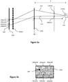
Figure 2a and 2b illustrate the relationship between the micro-images captured by the sensor of the camera offigure 1 and the corresponding sub-aperture images; -
Figure 3a and 3b illustrate an optical property of the type I plenoptic camera offigure 1 ; -
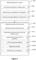
Figure 4 illustrates a flowchart of a method for predicting a component of a current pixel as implemented in the encoder and decoder offigure 1 according to at least one embodiment; -
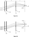
Figure 5a illustrates first and second rays as involved in the method offigure 4 ; -
Figure 5b illustrates a location determined on the sensor of the type I plenoptic camera offigure 1 by applying the method offigure 4 ; -
Figure 6 illustrates an exemplary system that can be used for implementing the method offigure 4 . - In all of the figures, the same numerical reference signs designate similar elements and steps.
- A method for predicting a component (e.g. a chrominance or luminance) of a current pixel belonging to a current sub-aperture image in a matrix of sub-aperture images captured by a sensor of a type I plenoptic camera is disclosed. Such method comprises a step of determining a location on the sensor based on parameters of the camera. Based on such determined location, the component of the current pixel is predicted based at least on one reference pixel belonging to a reference sub-aperture image in the matrix and located on the sensor in a neighborhood of the determined location.
- The prediction relying only on parameters of the camera, the derivations can be performed e.g. on both the encoding side and the decoding side based on a small number of parameters to be shared in between the devices.
-
Figure 1 depicts anencoder 120 and adecoder 130 respectively encoding and decoding a current pixel of a sub-aperture image of anobject 110 captured by a type Iplenoptic camera 100 according to at least one embodiment. - As illustrated in
figure 1 , the type Iplenoptic camera 100 comprises amain lens 1001, a micro-lens array 100mla and asensor 100s. - Three axes define the coordinate system (CS) of the camera. More particularly, when the
camera 100 is pointed toward theobject 110 that is being captured: - the z axe of the CS is defined as originating from the entry pupil (i.e. the optical image of the aperture stop as seen from the front of the camera) of the camera with z positive in the scene;
- the x axe of the CS is defined as originating from the entry pupil of the camera, extending horizontally and pointing toward the right; and
- the y axe of the CS is defined as originating from the entry pupil of the camera, extending vertically and pointing toward the bottom.
- According to these definition, the entry pupil is located in the plane defined by z=0 in the CS.
- When capturing the
object 110 at a given instant, the type Iplenoptic camera 100 delivers a matrix 200sai (figure 2b ) of sub-aperture images belonging to a LF. In the embodiment illustrated infigure 2b , the matrix 200sai of sub-aperture images comprises four sub-aperture images comprising six pixels each. - Each sub-aperture image is composed of pixels belonging to all the micro-images of the matrix 200mi (
figure 2a ) of micro-images captured by thesensor 100s, one micro-image being located in front of a corresponding micro-lens of the array 100mla of micro-lenses. More particularly: - the top left pixel of sub-aperture image 200sai1 corresponds to the top left pixel 200miltl of the micro-image 200mi1;
- the top center pixel of sub-aperture image 200sai1 corresponds to the top left pixel 200mi2tl of the micro-image 200mi2;
- the top right pixel of sub-aperture image 200sai1 corresponds to the top left pixel 200mi3tl of the micro-image 200mi3;
- the bottom left pixel of sub-aperture image 200sail corresponds to the top left pixel 200mi4tl of the micro-image 200mi4;
- the bottom center pixel of sub-aperture image 200sail corresponds to the top left pixel 200mi5tl of the micro-image 200mi5; and
- the bottom right pixel of sub-aperture image 200sail corresponds to the top left pixel 200mi6tl of the micro-image 200mi6.
- The same holds for the other sub-aperture images of the matrix 200sai. For instance:
- the top left pixel of sub-aperture image 200sai2 corresponds to the top right pixel 200miltr of the micro-image 200mi1;
- the top center pixel of sub-aperture image 200sai2 corresponds to the top right pixel 200mi2tr of the micro-image 200mi2;
- etc.
- There is thus a same number of pixels per micro-image, i.e. four pixels per micro-image in the present embodiment, for being able to reconstruct the four sub-aperture images of six pixels each of the matrix 200sai.
- The matrix 200sai of sub-aperture images is delivered to an
encoder 120. The encoder comprises adevice 150 that is configured for predicting a component of a current pixel according to the method illustrated onfigure 4 . - A prediction residue can be derived between the prediction and the effective value of a component of a pixel of a given sub-aperture image belonging to the matrix 200sai, the prediction being based on a reference sub-aperture image also belonging to the matrix 200sai. The prediction residue can then be encoded in a bitstream.
- The encoding of the successive matrices of sub-aperture images captured by the
camera 100 delivers a bitstream carrying the LF captured by the type Iplenoptic camera 100. Such bitstream can be transferred to thedecoder 130 that also comprises asame device 150 as theencoder 120. - The
decoder 130 can predict a value of a component of a pixel of a given sub-aperture image belonging to the matrix 200sai based at least on a reference sub-aperture image belonging to the matrix 200sai and on parameters of the type Iplenoptic camera 100 used to capture the LF. - The parameters of the type I
plenoptic camera 100 are supposed to be known by thedecoder 130, more particularly by thedevice 150. For instance, the bitstream carrying the LF captured by thesensor 100s of the type Iplenoptic camera 100 and transmitted by theencoder 120 to thedecoder 130 comprise metadata with said parameters. As discussed below in relation withfigure 4 , in at least one embodiment such parameters comprise a distance D from the exit pupil of themain lens 1001 to the micro-lens array 100mla, the focal length F of themain lens 1001, a focal length f of the micro-lenses of the micro-lens array 100mla, and a set of parameters of a model of the camera (e.g. pattern, position and orientation of the micro-lens array) 100 allowing for a derivation of a two-plane parameterization describing the field of rays corresponding to the pixels of the sensor. The set of rays in a light field can be parameterized in a variety of ways. Of these, the most common is the two-plane parameterization. - The property of the type I
plenoptic camera 100 according to which all the waists of the ray bundles corresponding to the pixels belonging to a same sub-aperture image reach a same point in the object focal plane of thecamera 100 is illustrated byfigures 3a and 3b . - More particularly, as for any type I plenoptic camera, the
sensor 100s is located in the image focal plane (i.e. in the plane of equation z=-D-f in the CS) of the micro-lens array 100mla (i.e. each pixel of the sensor is at a distance f of the micro-lens array 100mla). Consequently, a ray bundle originating from a given pixel on the sensor and encompassing a given micro-lens of the micro-lens array 100mla results in parallel rays in between the considered given micro-lens and themain lens 1001. The parallel rays are further collimated by themain lens 1001 so that they all converge toward a given focal point in the object focal plane of the main lens 1001 (i.e. in the plane of equation z=F in the CS). - For instance, as illustrated in
figure 3a , the ray bundle corresponding to the top left pixel 200miltl of sub-aperture image 200sail (that thus corresponds to the top left pixel 200miltl of the micro-image 200mi1 as discussed above in relation withfigures 2a and 2b ) converges toward a single point 300sai1 (thus corresponding to the waist of the ray bundle) in the object focal plane of themain lens 1001. - Furthermore, due to this particular disposition of the optical system of type I plenoptic camera, it happens that all the ray bundles corresponding to the pixels of the same sub-aperture image all converge toward the same single point in the object focal plane of the
main lens 1001. In other words, all the ray bundles corresponding to the pixels of the same sub-aperture image share a common waist that is located in the object focal plane of themain lens 1001. - For instance, the ray bundle corresponding to the top center pixel 200mi2tl of sub-aperture image 200sail (that thus corresponds to the top left pixel 200mi2tl of the micro-image 200mi2 as discussed above in relation with
figures 2a and 2b ) also converges toward the point 300sai1 as do the ray bundle corresponding to the top left pixel 200miltl. The point 300sai1 in the object focal plane of themain lens 1001 is thus the common waist of the ray bundles corresponding to the pixels belonging to the sub-aperture image 200sai1. - The same holds for the pixels of any sub-aperture image of the matrix 200sai. For instance, the ray bundle corresponding to the top center pixel 200mi2tr of sub-aperture image 200sai2 (that thus corresponds to the top right pixel 200mi2tr of the micro-image 200mi2 as discussed above in relation with
figures 2a and 2b ) also converges toward the point 300sai2 as do the ray bundle corresponding to the top left pixel 200miltr of sub-aperture image 200sai2 as illustrated infigure 3b . The point 300sai2 in the object focal plane of themain lens 1001 is thus the common waist of the ray bundles corresponding to the pixels belonging to the sub-aperture image 200sai2. - Consequently, a common waist of the ray bundles corresponding to the pixels belonging to the same sub-aperture image can be uniquely defined for each sub-aperture image of the matrix 200sai of sub-aperture images.
-
Figure 4 illustrates a method for predicting a component of a current pixel according to at least one embodiment. Such method can be implemented for instance in theencoder 120 and/or in thedecoder 130. The corresponding steps are detailed through an example discussed in reference tofigures 5a and 5b . - As an example, let consider that the considered current pixel is the pixel 200mi2tr belonging to the current sub-aperture image that is assumed to be the sub-aperture image 200sai2.
- In a step S400, a
location 500 is determined on thesensor 100s based on the following parameters of the camera 100: - the distance D from the exit pupil of the main lens 100l of the
camera 100 to the micro-lens array 100mla of thecamera 100; - the focal length F of the
main lens 1001; - the focal length f of the micro-lenses of the micro-lens array 100mla; and
- a set of parameters (e.g. pattern, position and orientation of the micro-lens array) of a model of the
camera 100 allowing for a derivation of a two-plane parameterization describing the field of rays corresponding to the pixels of thesensor 100s. - More particularly, the
location 500 is expected to be close to one or more reference pixel(s) on thesensor 100s that belong(s) to a reference sub-aperture image, assumed to be the sub-aperture image 200sail in the present example, and that captured a same object point as the current pixel. - For that, the property discussed above in relation with
figures 3a and 3b according to which a common waist of the ray bundles corresponding to the pixels belonging to the same sub-aperture image can be uniquely defined for each sub-aperture image of the matrix 200sai of sub-aperture images is used. - More particularly, as illustrated in
figure 5a , an object point 550op located at depth Z along afirst ray 510 corresponding to the current pixel 200mi2tr is determined based on the set of parameters of the model of thecamera 100. Here, the depth Z is a depth associated with the considered current pixel 200mi2tr. For instance, the depth Z is determined by treatment of the current sub-aperture image 200sai2 to which the current pixel 200mi2tr belongs. In that case the object point belongs to theobject 110 captured by thecamera 100. In another variant, the depth Z is captured by a dedicated depth sensor of thecamera 100 at the same time than the current sub-aperture image 200sai2 is captured. In yet other variants, the depth Z is provided as a default value. - The
location 500 is determined as the intersection with thesensor 100s of asecond ray 520 originating from the object point 550op and passing through the common waist 300sai1 of the ray bundles corresponding to the pixels belonging to a reference sub-aperture image 200sai1. Due to this constraint of passing through the common waist 300sai1, it can be expected that thesecond ray 520 matches an effective ray that reaches a reference pixel belonging to the reference sub-aperture image 200sail that captured the same object point 550op than the considered current pixel 200mi2tr. According to that, it can be expected that thelocation 500 coincide with one reference pixel or at least is close to reference pixel(s) belonging to the reference sub-aperture image 200sai1. It is therefore meaningful to predict one or more component(s) of the current pixel 200mi2tr based on component(s) of the reference pixel(s) belonging to the reference sub-aperture image 200sail and located on thesensor 100s in a neighborhood of thelocation 500. - Back to
figure 4 , for determining thetheoretical location 500 the coordinates
main lens 1001 in a step S400a. Indeed, as discussed above in relation with thefigures 3a and 3b , such common waist 300sai2 can be uniquely determined in the object focal plane (i.e. in the plane of equation z=F in the CS) of thecamera 100. In the same way, the coordinates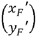
camera 100. - In the considered embodiment, the two-plane parameterization comprises I 0[i,j,u,v] and I 1[i,j,u,v] defining respectively the intersection with the plane z = 0 and z = 1, in the CS, of a chief ray corresponding to a pixel of position (u,v) in the sub-aperture image of index (i,j) in the matrix 200sai of sub-aperture images.
- In that case, the coordinates



- F the focal length of the
main lens 1001; - (ic ,jc ) the indexes of the current sub-aperture image 200sai2 in the matrix 200sai of sub-aperture images;
- (uca , vca ) the coordinates of any pixel in the current sub-aperture image 200sai2.
- (ir ,jr ) the indexes of the reference sub-aperture image 200sail in the matrix 200sai of sub-aperture images; and
- (ura ,vra ) the coordinates of any pixel in the reference sub-aperture image 200sai1.
- In other embodiments, the two-plane parameterization comprises I z0[i,j,u,v] and I z1[i,j,u,v] defining respectively the intersection of chief rays with other planes than the plane z = 0 and z = 1, in the CS, e.g. z = z0 and z = z1. In that case, the linear interpolation defined through (Eq-1a) and (Eq-1b) can be respectively rewritten as:


- In still other embodiments, the two-plane parameterization defines intersection of other reference rays than chief rays with two different planes.
- In a step S400b, first coordinates of an intersection, with a given plane, of the
first ray 510 corresponding to the current pixel 200mi2tr are determined. - In the present embodiment the given plane is the plane z = 0 in the CS and the
first ray 510 is a chief ray corresponding to the current pixel 200mi2tr on thesensor 100s. - In that case, the first coordinates,


- (ic , jc ) the indexes of the current sub-aperture image 200sai2 in the matrix 200sai of sub-aperture images; and
- (uc ,vc ) the coordinates of the current pixel 200mi2tr in the current sub-aperture image 200sai2.
- In other embodiments, the given plane is the plane z = z0 in the CS and (Eq-2) can be rewritten using the parametrization I z0[i,j,u,v] instead of I 0[i,j,u,v].
- in still other embodiments, the two-plane parameterization defines intersection of other reference rays than chief rays with two different planes.
- In a step S400c, second coordinates of an intersection, with the same given plane as used for defining the first coordinates, of the
second ray 520 coming from the object point 550op located at depth Z along thefirst ray 510 and passing through the common waist 300sai1 of the ray bundles corresponding to the pixels belonging to a reference sub-aperture image 200sail are calculated. - In the present embodiment where the considered given plane is the plane z = 0 in the CS and the
first ray 510 is a chief ray corresponding to the current pixel 200mi2tr on thesensor 100s, the coordinates in the CS,
first ray 510 can be expressed as a linear interpolation of the coordinates

first ray 510 with the plane z = 0 and z = F respectively) as:
- Equivalently, the coordinates


second ray 520 as: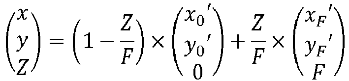
- By equating the two previous expressions for the coordinates


- F the focal length of the
main lens 1001; and - Z the depth associated to the current pixel 200mi2tr.
- In other embodiments where the given plane is the plane z = z0 in the CS and where (Eq-2) can be rewritten using the parametrization I z0[i,j,u,v] instead of I 0[i,j,u,v], (Eq-3) can be rewritten as:

-

-

- F the focal length of the
main lens 1001; and - Z the depth associated to the current pixel 200mi2tr.
- However, selecting the given plane as the plane z = 0 in the CS allows more simple derivations and less parameters to share in between the
encoder 120 and thedecoder 130. - Furthermore, having selected the given plane as the plane z = 0 allows deriving the coordinates

location 500 in a straightforward manner based on the coordinates

second ray 520 by the main lens 1101 and by the micro-lenses of the array 100mla remain weak (assumption that is exact when thesecond ray 520 directly goes through the center of the considered lens or micro-lens), one can write that:
second ray 520 in the plane (x,z) of the CS and the z axis, and θy the angle between the projection of thesecond ray 520 in the plane (y,z) of the CS and the z axis. - Assuming furthermore that the focal length F of the
main lens 1001 is much greater than any component of the coordinates

- So that finally:

- Having determined the coordinates of the
location 500 on thesensor 100s, in a step S410 at least one component of the current pixel 200mi2tr is predicted based on component(s) of one or more reference pixel(s) belonging to the reference sub-aperture image 200sail and located on thesensor 100s in a neighborhood of thelocation 500. - For that, in a step S410a, at least two reference pixels belonging to the reference sub-aperture image 200sail in the matrix 200sai and located on the
sensor 100s in the neighborhood of thelocation 500 are selected (e.g. based on an Euclidian metric, etc.). - In a step S410b, a component of said at least two reference pixels is interpolated (e.g. a linear or bilinear interpolation, a bicubic interpolation, a Lanczos interpolation, etc.) for delivering an interpolated component. In that case, the predicted component of the current pixel 200mi2tr is a function of the interpolated component (e.g. proportional to, etc.).
- However, in other embodiments not illustrated, a single reference pixel belonging to the reference sub-aperture image 200sail and located on the
sensor 100s in the neighborhood of thelocation 500 is selected. In that case, the predicted component of the current pixel 200mi2tr is directly derived from a component of the selected reference pixel (e.g. the value of the component of the selected reference pixel is assigned to the current pixel 200mi2tr as the predicted component). - Back to
figure 4 , in a step S410b1, the coordinates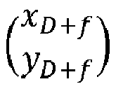
location 500 are expressed as a barycenter of the coordinates of said at least two reference pixels. For each considered reference pixel among said at least two reference pixels: - in a step S410b2, the coefficient weighting the coordinates of the considered reference pixel in the barycenter expression are extracted; and
- in a step S410b3, a component of the considered reference pixel is weighted with the corresponding extracted coefficient.
- Then, in a step S410b4, the linear combination of the weighted components is performed for delivering the interpolated component.
- For instance, let consider as an illustrative example that the four reference pixels selected in the close neighborhood of the
location 500 are pixels 200miltl, 200mi2tl, 200mi4tl and 200mi5tl (figure 5b ). In that case, the coordinates
location 500 can be expressed as the barycenter expression:
-

-

- xl stands for the common abscise of reference pixels 200miltl and 200mi4tl;
- xr stands for the common abscise of reference pixels 200mi2tl and 200mi5tl;
- yt stands for the common ordinate of reference pixels 200miltl and 200mi2tl; and
- yb stands for the common ordinate of reference pixels 200mi4tl and 200mi5tl.
- Application of steps S410b2, S410b3 and S410b4 to the above barycenter expression leads to the following expression for the predicted component Ŷ of the current pixel 200mi2tr:

- Ytl the component of the reference pixel 200miltl;
- Ytr the component of the reference pixel 200mi2tl;
- Ybl the component of the reference pixel 200mi4tl; and
- Ybr the component of the reference pixel 200mi5tl.
- The prediction method can thus be part of an encoding method and/or of a decoding method. To this aim, on the encoder side, a residue between the component Y and the predicted component Ŷ of the current pixel is then encoded in the bitstream.
On the decoder side, a residue is decoded from the bitstream and a component Y is reconstructed by adding the predicted component Ŷ of the current pixel to the decoded residue. -
Figure 6 illustrates a block diagram of an exemplary system in which various aspects and exemplary embodiments are implemented.System 1000 is a particular way of implementing theencoder 120 and/or thedecoder 130 and can be embodied as a device including the various components described below and is configured to perform one or more of the aspects described in this document. Examples of such devices, include, but are not limited to, personal computers, laptop computers, smartphones, tablet computers, digital multimedia set top boxes, digital television receivers, personal video recording systems, connected home appliances, and servers.System 1000 can be communicatively coupled to other similar systems, and to a display via a communication channel as shown inFigure 6 and as known by those skilled in the art to implement the various aspects described in this document. - The
system 1000 can include at least oneprocessor 1010 configured to execute instructions loaded therein for implementing the various aspects described in this document.Processor 1010 can include embedded memory, input output interface, and various other circuitries as known in the art. Thesystem 1000 can include at least one memory 1020 (e.g., a volatile memory device, a non-volatile memory device).System 1000 can include astorage device 1040, which can include non-volatile memory, including, but not limited to, EEPROM, ROM, PROM, RAM, DRAM, SRAM, flash, magnetic disk drive, and/or optical disk drive. Thestorage device 1040 can include an internal storage device, an attached storage device, and/or a network accessible storage device, as non-limiting examples.System 1000 can include an encoder/decoder module 1030 configured to process data to provide an encoded video or decoded video, and the encoder/decoder module 1030 can include its own processor and memory. The encoder/decoder module 1030 is configured to implement the prediction method according to at least one embodiment and thus includes adevice 150 configured for predicting a component of a current pixel according to the method illustrated onfigure 4 (according to any of its embodiments).Such device 150 can include its own processor and memory. - Encoder/
decoder module 1030 represents the module(s) that can be included in a device to perform the encoding and/or decoding functions. As is known, a device can include one or both of the encoding and decoding modules. Additionally, encoder/decoder module 1030 can be implemented as a separate element ofsystem 1000 or can be incorporated withinprocessors 1010 as a combination of hardware and software as known to those skilled in the art. - Program code to be loaded onto
processors 1010 to perform the various aspects described in this document can be stored instorage device 1040 and subsequently loaded ontomemory 1020 for execution byprocessors 1010. In accordance with the exemplary embodiments, one or more of the processor(s) 1010,memory 1020,storage device 1040, and encoder/decoder module 1030 can store one or more of the various items during the performance of the processes described in this document, including, but not limited to the input video, the decoded video, the bitstream, equations, formulas, matrices, variables, operations, and operational logic. - The
system 1000 can includecommunication interface 1050 that enables communication with other devices viacommunication channel 1060. Thecommunication interface 1050 can include, but is not limited to, a transceiver configured to transmit and receive data fromcommunication channel 1060. Thecommunication interface 1050 can include, but is not limited to, a modem or network card and the communication channel can be implemented within a wired and/or a wireless medium. The various components ofsystem 1000 can all be connected or communicatively coupled together using various suitable connections, including, but not limited to internal buses, wires, and printed circuit boards. - The exemplary embodiments can be carried out by computer software implemented by the
processor 1010 or by hardware, or by a combination of hardware and software. As a non-limiting example, the exemplary embodiments can be implemented by one or more integrated circuits. Thememory 1020 can be of any type appropriate to the technical environment and can be implemented using any appropriate data storage technology, such as optical memory devices, magnetic memory devices, semiconductor-based memory devices, fixed memory, and removable memory, as non-limiting examples. Theprocessor 1010 can be of any type appropriate to the technical environment, and can encompass one or more of microprocessors, general purpose computers, special purpose computers, and processors based on a multi-core architecture, as non-limiting examples. - The implementations and aspects described herein can be implemented in, for example, a method or a process, an apparatus, a software program, a data stream, or a signal. Even if only discussed in the context of a single form of implementation (for example, discussed only as a method), the implementation of features discussed can also be implemented in other forms (for example, an apparatus or program). An apparatus can be implemented in, for example, appropriate hardware, software, and firmware. The methods can be implemented in, for example, an apparatus such as, for example, a processor, which refers to processing devices in general, including, for example, a computer, a microprocessor, an integrated circuit, or a programmable logic device. Processors also include communication devices, such as, for example, computers, cell phones, portable/personal digital assistants ("PDAs"), and other devices that facilitate communication of information between end-users.
- Reference to "one embodiment" or "an embodiment" or "one implementation" or "an implementation", as well as other variations thereof, mean that a particular feature, structure, characteristic, and so forth described in connection with the embodiment is included in at least one embodiment. Thus, the appearances of the phrase "in one embodiment" or "in an embodiment" or "in one implementation" or "in an implementation", as well any other variations, appearing in various places throughout this document are not necessarily all referring to the same embodiment.
- Additionally, this document may refer to "determining" various pieces of information. Determining the information can include one or more of, for example, estimating the information, calculating the information, predicting the information, or retrieving the information from memory.
- Further, this document may refer to "accessing" various pieces of information. Accessing the information can include one or more of, for example, receiving the information, retrieving the information (for example, from memory), storing the information, processing the information, transmitting the information, moving the information, copying the information, erasing the information, calculating the information, determining the information, predicting the information, or estimating the information.
- Additionally, this document may refer to "receiving" various pieces of information. Receiving is, as with "accessing", intended to be a broad term. Receiving the information can include one or more of, for example, accessing the information, or retrieving the information (for example, from memory). Further, "receiving" is typically involved, in one way or another, during operations such as, for example, storing the information, processing the information, transmitting the information, moving the information, copying the information, erasing the information, calculating the information, determining the information, predicting the information, or estimating the information.
- As will be evident to one of ordinary skill in the art, implementations can produce a variety of signals formatted to carry information that can be, for example, stored or transmitted. The information can include, for example, instructions for performing a method, or data produced by one of the described implementations. For example, a signal can be formatted to carry the bitstream of a described embodiment. Such a signal can be formatted, for example, as an electromagnetic wave (for example, using a radio frequency portion of spectrum) or as a baseband signal. The formatting can include, for example, encoding a data stream and modulating a carrier with the encoded data stream. The information that the signal carries can be, for example, analog or digital information. The signal can be transmitted over a variety of different wired or wireless links, as is known. The signal can be stored on a processor-readable medium.
- According to one embodiment, a method is proposed for predicting a component of a current pixel belonging to a current sub-aperture image in a matrix of sub-aperture images captured by a sensor of a type I plenoptic camera. Such method comprises:
- determining a location on the sensor based at least on:
- a distance D from an exit pupil of a main lens of the camera to a micro-lens array of the camera;
- a focal length F of the main lens;
- a focal length f of the micro-lenses of the micro-lens array; and
- a set of parameters of a model of the camera allowing for a derivation of a two-plane parameterization describing the field of rays corresponding to the pixels of the sensor;
- predicting the component of the current pixel based on at least one reference pixel belonging to a reference sub-aperture image in the matrix and located on the sensor in a neighborhood of the location.
- Thus, the present disclosure proposes a new and inventive solution for predicting a component (e.g. a chrominance or luminance) of a current pixel of a sub-aperture image in a light field captured by a type I plenoptic camera.
- More particularly, this prediction relies among other on a two-plane parameterization that leads to improved prediction results compared to simple pinhole models as assumed for instance in the VSP technic.
- Furthermore, having that only parameters of the camera are used, the derivations can be performed e.g. on both the encoding side and the decoding side based on a small number of parameters to be shared in between the devices. Furthermore, the physical parameters of the camera are static parameters so that there is no need for a frequent update thus minimizing further the overhead cost on top of the light field data.
- According to one embodiment, a device is proposed for predicting a component of a current pixel belonging to a current sub-aperture image in a matrix of sub-aperture images captured by a sensor of a type I plenoptic camera. Such device comprises a processor configured for:
- determining a location on the sensor based at least on:
- a distance D from an exit pupil of a main lens of the camera to a micro-lens array of the camera;
- a focal length F of the main lens;
- a focal length f of the micro-lenses of the micro-lens array; and
- a set of parameters of a model of the camera allowing for a derivation of a two-plane parameterization describing the field of rays corresponding to the pixels of the sensor;
- predicting the component of the current pixel based on at least one reference pixel belonging to a reference sub-aperture image in the matrix and located on the sensor in a neighborhood of the location.
- According to one embodiment, the location is determined as an intersection with the sensor of a second ray originating from an object point and passing through a common waist of the ray bundles corresponding to the pixels belonging to a reference sub-aperture image in the matrix, the object point being located at depth Z along a first ray corresponding to the current pixel.
- According to one embodiment, the determining the location comprises:
- determining in the object focal plane of the camera:
- coordinates

- coordinates

- coordinates
- determining first coordinates of an intersection, with a given plane, of the first ray corresponding to the current pixel on the sensor; and
- calculating second coordinates of an intersection, with the given plane, of the second ray corresponding to the location on the sensor and coming from the object point located at depth Z along the first ray, based at least on the first coordinates, on the coordinates


- Thus, the property of type I plenoptic cameras according to which the ray bundles corresponding to the pixels belonging to the same sub-aperture image have a common waist in the object focal plane (i.e. the plane corresponding to z=F in the coordinate system of the camera) allows straightforward derivations based on optical geometry considerations. According to one embodiment, the two-plane parameterization comprises I 0[i,j,u,v] and I 1[i,y,u,v] defining respectively the intersection with the plane z = 0 and z = 1, in the coordinate system of the camera, of a chief ray corresponding to a pixel of position (u,v) in the sub-aperture image of index (i,j) in the matrix of sub-aperture images. The object focal plane is the plane z = F in the coordinate system of the camera. The determining the coordinates




- F the focal length;
- (ic ,jc ) the indexes of the current sub-aperture image in the matrix of sub-aperture images;
- (uca ,vca ) the coordinates of any pixel in the current sub-aperture image.
- (ir ,jr ) the indexes of the reference sub-aperture image in the matrix of sub-aperture images; and
- (ura ,vra ) the coordinates of any pixel in the reference sub-aperture image.
- In other words, the coordinates


- According to one embodiment, the given plane is the plane z = 0 in the coordinate system of the camera. The determining first coordinates enforces the relationship

with: -

- (ic , jc ) the indexes of the current sub-aperture image in the matrix of sub-aperture images; and
- (uc ,vc ) the coordinates of the current pixel in the current sub-aperture image.
- According to one embodiment, the the calculating second coordinates enforces the equation

-

- F the focal length; and
- Z the depth.
- According to one embodiment, the plane of the sensor is the plane z = -D-f in the coordinate system of the camera,
and wherein the determining the location enforces the equation
-

- F the focal length;
- f the focal length of the micro-lenses of the micro-lens array; and
- D the distance from the exit pupil of the main lens of the camera to the micro-lens array of the camera.
- According to one embodiment, the predicting the component of the current pixel comprises:
- selecting at least two reference pixels belonging to the reference sub-aperture image in the matrix and located on the sensor in the neighborhood of the location; and
- interpolating a component of each of the at least two reference pixels delivering an interpolated component.
- The predicted component of the current pixel is a function of the interpolated component (e.g. a linear or bilinear interpolation, a bicubic interpolation, a Lanczos interpolation, etc.)
- According to one embodiment, the interpolating comprises:
- expressing the location as a barycenter of the coordinates of the at least two reference pixels on the sensor; and for each considered reference pixel among the at least two reference pixels:
- extracting the coefficient weighting the coordinates of the considered reference pixel in the barycenter expression;
- weighting a component of the considered reference pixel with the corresponding extracted coefficient; and
- performing the linear combination of the weighted components delivering the interpolated component.
- Thus, the interpolation is simple and robust.
- According to one embodiment, a bitstream carrying a light field captured by a sensor of a type I plenoptic camera is proposed. Such bitstream comprises metadata comprising:
- a distance D from an exit pupil of a main lens of the camera to a micro-lens array of the camera;
- a focal length F of the main lens;
- a focal length f of the micro-lenses of the micro-lens array; and
- a set of parameters of a model of the camera allowing for a derivation of a two-plane parameterization describing the field of rays corresponding to the pixels of the sensor.
- According to one embodiment, a non-transitory computer readable medium comprising a computer program product recorded thereon and capable of being run by a processor, including program code instructions comprising program code instructions for implementing a method for predicting a component of a current pixel belonging to a current sub-aperture image in a matrix of sub-aperture images captured by a sensor of a type I plenoptic camera previously described is proposed.
- According to one embodiment, an encoding method is proposed comprising the method for predicting a component of a current pixel belonging to a current sub-aperture image in a matrix of sub-aperture images captured by a sensor of a type I plenoptic camera as disclosed above (in any of its embodiments).
- According to one embodiment, a decoding method is proposed comprising the method for predicting a component of a current pixel belonging to a current sub-aperture image in a matrix of sub-aperture images captured by a sensor of a type I plenoptic camera as disclosed above (in any of its embodiments).
- According to one embodiment, an encoder is proposed comprising a device for predicting a component of a current pixel belonging to a current sub-aperture image in a matrix of sub-aperture images captured by a sensor of a type I plenoptic camera as disclosed above (in any of its embodiments).
- According to one embodiment, a decoder is proposed comprising a device for predicting a component of a current pixel belonging to a current sub-aperture image in a matrix of sub-aperture images captured by a sensor of a type I plenoptic camera as disclosed above (in any of its embodiments).

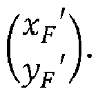
Claims (13)
- Method for predicting a component of a current pixel (200mi2tr) belonging to a current sub-aperture image (200sai2) in a matrix (200sai) of sub-aperture images captured by a sensor of a type I plenoptic camera (100), the method being intended to be implemented in an encoder (120) and/or in a decoder (130),
wherein it comprises:- determining (S400) a location on said sensor based at least on:- a distance D from an exit pupil of a main lens (1001) of said camera to a micro-lens array (100mla) of said camera;- a focal length F of the main lens;- a focal length f of the micro-lenses of the micro-lens array; and- a set of parameters of a model of said camera allowing for a derivation of a two-plane parameterization describing the field of rays corresponding to the pixels of the sensor;- predicting (S410) said component of said current pixel based on at least one reference pixel belonging to a reference sub-aperture image in said matrix and located on said sensor in a neighborhood of said location. - Device for predicting a component of a current pixel (200mi2tr) belonging to a current sub-aperture image (200sai2) in a matrix (200sai) of sub-aperture images captured by a sensor of a type I plenoptic camera (100),
wherein it comprises a processor (1005) configured for:- determining a location on said sensor based at least on:- a distance D from an exit pupil of a main lens (1001) of said camera to a micro-lens array (100mla) of said camera;- a focal length F of the main lens;- a focal length f of the micro-lenses of the micro-lens array; and- a set of parameters of a model of said camera allowing for a derivation of a two-plane parameterization describing the field of rays corresponding to the pixels of the sensor;- predicting said component of said current pixel based on at least one reference pixel belonging to a reference sub-aperture image in said matrix and located on said sensor in a neighborhood of said location. - Method according to claim 1 or device according to claim 2 wherein said location is determined as an intersection with said sensor of a second ray (520) originating from an object point (550op) and passing through a common waist (300sai1) of the ray bundles corresponding to the pixels belonging to a reference sub-aperture image (200sai1) in said matrix, said object point (550op) being located at depth Z along a first ray (510) corresponding to the current pixel (200mi2tr).
- Method according to claim 3 or device according to claim 3 wherein said determining said location comprises:- determining (S400a) in the object focal plane of the camera:- coordinates
 - coordinates
 - determining (S400b) first coordinates of an intersection, with a given plane, of said first ray corresponding to the current pixel on the sensor; and- calculating (S400c) second coordinates of an intersection, with said given plane, of said second ray corresponding to said location on the sensor and coming from said object point located at depth Z along said first ray, based at least on said first coordinates, on said coordinatesand wherein coordinates of said location,


- Method according to claim 4 or device according to claim 4
wherein said two-plane parameterization comprises I0 [i,y,u,v] and I 1[i,y,u,v] defining respectively the intersection with the plane z = 0 and z = 1, in the coordinate system of the camera, of a chief ray corresponding to a pixel of position (u, v) in the sub-aperture image of index (i,j) in said matrix of sub-aperture images,
wherein said object focal plane is the plane z = F in the coordinate system of the camera, and wherein said determining the coordinates
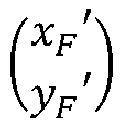


with:- F said focal length;- (ic , jc ) the indexes of the current sub-aperture image in said matrix of sub-aperture images;- (uca ,vca ) the coordinates of any pixel in said current sub-aperture image.- (ir ,jr ) the indexes of the reference sub-aperture image in said matrix of sub-aperture images; and- (ura ,vra ) the coordinates of any pixel in said reference sub-aperture image. - Method according to claim 5 or device according to claim 5
wherein said given plane is the plane z = 0 in the coordinate system of the camera, wherein said determining first coordinates enforces the relationship -
 - (ic , jc ) said indexes of the current sub-aperture image in said matrix of sub-aperture images; and- (uc ,vc ) the coordinates of said current pixel in said current sub-aperture image.
- Method according to claim 6 or device according to claim 6
wherein said calculating second coordinates enforces the equation -
 - F said focal length; and- Z said depth.
- Method according to claim 6 or 7 or device according to claim 6 or 7
wherein said plane of the sensor is the plane z = -D-f in the coordinate system of the camera, and wherein said determining said location enforces the equation -
 - F said focal length;- f said focal length of the micro-lenses of the micro-lens array; and- D said distance from the exit pupil of the main lens of the camera to the micro-lens array of the camera.
- Method according to any of the claims 1 and 3 to 8, or device according to any of claims 2 to 8
wherein said predicting said component of said current pixel comprises:- selecting (S410a) at least two reference pixels belonging to said reference sub-aperture image in said matrix and located on said sensor in said neighborhood of said location; and- interpolating (S410b) a component of each of said at least two reference pixels delivering an interpolated component,said predicted component of said current pixel being a function of said interpolated component. - Method according to claim 9 or device according to claim 9
wherein said interpolating comprises:- expressing (S410b1) said location as a barycenter of the coordinates of said at least two reference pixels on said sensor; and for each considered reference pixel among said at least two reference pixels:- extracting (S410b2) the coefficient weighting the coordinates of the considered reference pixel in said barycenter expression;- weighting (S410b3) a component of the considered reference pixel with the corresponding extracted coefficient; and- performing (S410b4) the linear combination of said weighted components delivering said interpolated component. - Bitstream carrying a light field captured by a sensor of a type I plenoptic camera (100), wherein it comprises metadata comprising:- a distance D from an exit pupil of a main lens (1001) of said camera to a micro-lens array (100mla) of said camera;- a focal length F of the main lens;- a focal length f of the micro-lenses of the micro-lens array; and- a set of parameters of a model of said camera allowing for a derivation of a two-plane parameterization describing the field of rays corresponding to the pixels of the sensor.
- Computer program product wherein it comprises program code instructions for implementing a method according to at least one of the claims 1 or 3 to 10, when said program is executed on a computer or a processor.
- A non-transitory computer-readable carrier medium storing a computer program product according to claim 12.
Priority Applications (9)
| Application Number | Priority Date | Filing Date | Title |
|---|---|---|---|
| EP18305684.5A EP3579561A1 (en) | 2018-06-05 | 2018-06-05 | Prediction for light-field coding and decoding |
| EP19730097.3A EP3804333A1 (en) | 2018-06-05 | 2019-05-29 | Prediction for light-field coding and decoding |
| US15/734,455 US11570471B2 (en) | 2018-06-05 | 2019-05-29 | Prediction for light-field coding and decoding |
| KR1020207038004A KR102895584B1 (en) | 2018-06-05 | 2019-05-29 | Prediction for light field coding and decoding |
| BR112020024663-8A BR112020024663A2 (en) | 2018-06-05 | 2019-05-29 | prediction for light field encoding and decoding |
| PCT/US2019/034308 WO2019236347A1 (en) | 2018-06-05 | 2019-05-29 | Prediction for light-field coding and decoding |
| CN202411218435.3A CN119520829A (en) | 2018-06-05 | 2019-05-29 | Method, medium and apparatus for prediction of light field encoding and decoding |
| CN201980045344.5A CN112385235B (en) | 2018-06-05 | 2019-05-29 | Prediction of light field encoding and decoding |
| US18/103,115 US12088841B2 (en) | 2018-06-05 | 2023-01-30 | Prediction for light-field coding and decoding |
Applications Claiming Priority (1)
| Application Number | Priority Date | Filing Date | Title |
|---|---|---|---|
| EP18305684.5A EP3579561A1 (en) | 2018-06-05 | 2018-06-05 | Prediction for light-field coding and decoding |
Publications (1)
| Publication Number | Publication Date |
|---|---|
| EP3579561A1 true EP3579561A1 (en) | 2019-12-11 |
Family
ID=62567579
Family Applications (2)
| Application Number | Title | Priority Date | Filing Date |
|---|---|---|---|
| EP18305684.5A Withdrawn EP3579561A1 (en) | 2018-06-05 | 2018-06-05 | Prediction for light-field coding and decoding |
| EP19730097.3A Pending EP3804333A1 (en) | 2018-06-05 | 2019-05-29 | Prediction for light-field coding and decoding |
Family Applications After (1)
| Application Number | Title | Priority Date | Filing Date |
|---|---|---|---|
| EP19730097.3A Pending EP3804333A1 (en) | 2018-06-05 | 2019-05-29 | Prediction for light-field coding and decoding |
Country Status (6)
| Country | Link |
|---|---|
| US (2) | US11570471B2 (en) |
| EP (2) | EP3579561A1 (en) |
| KR (1) | KR102895584B1 (en) |
| CN (2) | CN112385235B (en) |
| BR (1) | BR112020024663A2 (en) |
| WO (1) | WO2019236347A1 (en) |
Cited By (2)
| Publication number | Priority date | Publication date | Assignee | Title |
|---|---|---|---|---|
| CN111416983A (en) * | 2020-04-07 | 2020-07-14 | 清华大学深圳国际研究生院 | Multi-focal-length light field video intra-frame prediction method and device based on imaging correlation |
| US20220377374A1 (en) * | 2021-05-13 | 2022-11-24 | Samsung Eletrônica da Amazônia Ltda. | Method for four-dimensional intra-prediction coding and decoding of light field data |
Citations (2)
| Publication number | Priority date | Publication date | Assignee | Title |
|---|---|---|---|---|
| US20150319456A1 (en) * | 2014-04-30 | 2015-11-05 | Canon Kabushiki Kaisha | Method and device for encoding a sub-aperture image of a set of sub-aperture images obtained from a plenoptic image |
| EP3160142A1 (en) * | 2015-10-21 | 2017-04-26 | Thomson Licensing | Method for encoding and method for decoding a light field based image and corresponding devices |
Family Cites Families (17)
| Publication number | Priority date | Publication date | Assignee | Title |
|---|---|---|---|---|
| WO2013159330A1 (en) * | 2012-04-27 | 2013-10-31 | Nokia Corporation | An apparatus, a method and a computer program for video coding and decoding |
| US10158876B2 (en) | 2013-04-10 | 2018-12-18 | Qualcomm Incorporated | Backward view synthesis prediction |
| WO2015006967A1 (en) | 2013-07-19 | 2015-01-22 | Mediatek Singapore Pte. Ltd. | Simplified view synthesis prediction for 3d video coding |
| EP2879372A1 (en) * | 2013-11-29 | 2015-06-03 | Thomson Licensing | Method and device for processing a raw image acquired with a plenoptic camera |
| US9675430B2 (en) | 2014-08-15 | 2017-06-13 | Align Technology, Inc. | Confocal imaging apparatus with curved focal surface |
| US9743110B2 (en) | 2014-10-09 | 2017-08-22 | Hfi Innovation Inc. | Method of 3D or multi-view video coding including view synthesis prediction |
| EP3026628A1 (en) * | 2014-11-26 | 2016-06-01 | Thomson Licensing | Method and apparatus for estimating depth of unfocused plenoptic data |
| EP3026884A1 (en) * | 2014-11-27 | 2016-06-01 | Thomson Licensing | Plenoptic camera comprising a light emitting device |
| EP3065395A1 (en) * | 2015-03-05 | 2016-09-07 | Thomson Licensing | Processing of light field data |
| EP3088954A1 (en) * | 2015-04-27 | 2016-11-02 | Thomson Licensing | Method and device for processing a lightfield content |
| EP3142366A1 (en) * | 2015-09-14 | 2017-03-15 | Thomson Licensing | Method and apparatus for encoding and decoding a light field based image, and corresponding computer program product |
| CA2998670A1 (en) * | 2015-09-17 | 2017-03-23 | Thomson Licensing | Light field data representation |
| EP3351001B1 (en) * | 2015-09-17 | 2021-08-11 | InterDigital VC Holdings, Inc. | Method for encoding a light field content |
| EP3188123A1 (en) * | 2015-12-30 | 2017-07-05 | Thomson Licensing | A method and an apparatus for generating data representative of a pixel beam |
| EP3249607A1 (en) * | 2016-01-28 | 2017-11-29 | Thomson Licensing | Method for obtaining a position of a main lens optical center of a plenoptic camera |
| EP3220351A1 (en) * | 2016-03-14 | 2017-09-20 | Thomson Licensing | Method and device for processing lightfield data |
| EP3264759A1 (en) * | 2016-06-30 | 2018-01-03 | Thomson Licensing | An apparatus and a method for generating data representative of a pixel beam |
-
2018
- 2018-06-05 EP EP18305684.5A patent/EP3579561A1/en not_active Withdrawn
-
2019
- 2019-05-29 BR BR112020024663-8A patent/BR112020024663A2/en unknown
- 2019-05-29 CN CN201980045344.5A patent/CN112385235B/en active Active
- 2019-05-29 EP EP19730097.3A patent/EP3804333A1/en active Pending
- 2019-05-29 US US15/734,455 patent/US11570471B2/en active Active
- 2019-05-29 CN CN202411218435.3A patent/CN119520829A/en active Pending
- 2019-05-29 WO PCT/US2019/034308 patent/WO2019236347A1/en not_active Ceased
- 2019-05-29 KR KR1020207038004A patent/KR102895584B1/en active Active
-
2023
- 2023-01-30 US US18/103,115 patent/US12088841B2/en active Active
Patent Citations (2)
| Publication number | Priority date | Publication date | Assignee | Title |
|---|---|---|---|---|
| US20150319456A1 (en) * | 2014-04-30 | 2015-11-05 | Canon Kabushiki Kaisha | Method and device for encoding a sub-aperture image of a set of sub-aperture images obtained from a plenoptic image |
| EP3160142A1 (en) * | 2015-10-21 | 2017-04-26 | Thomson Licensing | Method for encoding and method for decoding a light field based image and corresponding devices |
Non-Patent Citations (3)
| Title |
|---|
| CHRISTOPHER HAHNE ET AL: "Baseline and Triangulation Geometry in a Standard Plenoptic Camera", INTERNATIONAL JOURNAL OF COMPUTER VISION., 20 August 2017 (2017-08-20), US, XP055426156, ISSN: 0920-5691, DOI: 10.1007/s11263-017-1036-4 * |
| RACHEL L BIERASINSKI ET AL: "Calibration of a plenoptic camera for use in three-dimensional particle tracking", 1 January 2014 (2014-01-01), XP055213557, Retrieved from the Internet <URL:http://www.me.rochester.edu/projects/dhkelley-lab/papers/rlbms.pdf> [retrieved on 20150915] * |
| S. YEA; A. VETRO: "View Synthesis Prediction for Multiview video coding", SIGNAL PROCESSING: IMAGE COMMUNICATION, vol. 24, no. 1-2, January 2009 (2009-01-01), pages 89 - 100, XP025884347, DOI: doi:10.1016/j.image.2008.10.007 |
Cited By (4)
| Publication number | Priority date | Publication date | Assignee | Title |
|---|---|---|---|---|
| CN111416983A (en) * | 2020-04-07 | 2020-07-14 | 清华大学深圳国际研究生院 | Multi-focal-length light field video intra-frame prediction method and device based on imaging correlation |
| CN111416983B (en) * | 2020-04-07 | 2022-03-15 | 清华大学深圳国际研究生院 | Multi-focal-length light field video intra-frame prediction method and device based on imaging correlation |
| US20220377374A1 (en) * | 2021-05-13 | 2022-11-24 | Samsung Eletrônica da Amazônia Ltda. | Method for four-dimensional intra-prediction coding and decoding of light field data |
| US11647225B2 (en) * | 2021-05-13 | 2023-05-09 | Samsung Eletrônica da Amazônia Ltda. | Method for four-dimensional intra-prediction coding and decoding of light field data |
Also Published As
| Publication number | Publication date |
|---|---|
| CN112385235A (en) | 2021-02-19 |
| WO2019236347A1 (en) | 2019-12-12 |
| KR102895584B1 (en) | 2025-12-05 |
| US11570471B2 (en) | 2023-01-31 |
| EP3804333A1 (en) | 2021-04-14 |
| KR20210018348A (en) | 2021-02-17 |
| US20210227258A1 (en) | 2021-07-22 |
| BR112020024663A2 (en) | 2021-03-02 |
| US20230179799A1 (en) | 2023-06-08 |
| US12088841B2 (en) | 2024-09-10 |
| CN119520829A (en) | 2025-02-25 |
| CN112385235B (en) | 2024-09-17 |
Similar Documents
| Publication | Publication Date | Title |
|---|---|---|
| EP3907995B1 (en) | Chroma block prediction method and device | |
| US10652577B2 (en) | Method and apparatus for encoding and decoding light field based image, and corresponding computer program product | |
| US20250139834A1 (en) | Scalable framework for point cloud compression | |
| US20200099955A1 (en) | Method and device for encoding and decoding a stack of images, and corresponding computer program product | |
| US12088841B2 (en) | Prediction for light-field coding and decoding | |
| US20260082089A1 (en) | Sparse tensor-based bitwise deep octree coding | |
| EP3142366A1 (en) | Method and apparatus for encoding and decoding a light field based image, and corresponding computer program product | |
| CN107396112A (en) | A kind of coding method and device, computer installation, readable storage medium storing program for executing | |
| US20250045971A1 (en) | Hybrid framework for point cloud compression | |
| US20190182503A1 (en) | Method and image processing apparatus for video coding | |
| US20170374388A1 (en) | Method and a device for encoding a signal representative of a light-field content | |
| CN115604528B (en) | Fisheye image compression, fisheye video stream compression, and panoramic video generation methods | |
| CN103916652A (en) | Method and device for generating disparity vector | |
| EP3147860A1 (en) | Method and apparatus for reducing the coding artefact of a light field based image, and corresponding computer program product | |
| EP2839437A1 (en) | View synthesis using low resolution depth maps | |
| US10944990B2 (en) | Method for encoding at least one matrix of image views obtained from data acquired by a plenoptic camera, and corresponding electronic devices | |
| US12155858B2 (en) | Method for encoding video using effective differential motion vector transmission method in omnidirectional camera, and method and device | |
| EP4437721A1 (en) | Outlier grouping based point cloud compression | |
| WO2025096197A1 (en) | Entropy bottleneck layer for learning-based mesh compression | |
| WO2025244774A1 (en) | Model sharing for point cloud compression | |
| WO2025184001A1 (en) | Learning-based image coding for 3d point cloud data, with each color component of a 2d image corresponding to a dimension of 3d cartesian coordinates of a point position | |
| CN118301357A (en) | Pixel chromaticity prediction method, device, electronic device and storage medium |
Legal Events
| Date | Code | Title | Description |
|---|---|---|---|
| PUAI | Public reference made under article 153(3) epc to a published international application that has entered the european phase |
Free format text: ORIGINAL CODE: 0009012 |
|
| AK | Designated contracting states |
Kind code of ref document: A1 Designated state(s): AL AT BE BG CH CY CZ DE DK EE ES FI FR GB GR HR HU IE IS IT LI LT LU LV MC MK MT NL NO PL PT RO RS SE SI SK SM TR |
|
| AX | Request for extension of the european patent |
Extension state: BA ME |
|
| RAP1 | Party data changed (applicant data changed or rights of an application transferred) |
Owner name: INTERDIGITAL VC HOLDINGS, INC. |
|
| STAA | Information on the status of an ep patent application or granted ep patent |
Free format text: STATUS: THE APPLICATION IS DEEMED TO BE WITHDRAWN |
|
| 18D | Application deemed to be withdrawn |
Effective date: 20200613 |