EP3579534A1 - Image processing apparatus that executes job, control method therefor, and storage medium - Google Patents
Image processing apparatus that executes job, control method therefor, and storage medium Download PDFInfo
- Publication number
- EP3579534A1 EP3579534A1 EP19178040.2A EP19178040A EP3579534A1 EP 3579534 A1 EP3579534 A1 EP 3579534A1 EP 19178040 A EP19178040 A EP 19178040A EP 3579534 A1 EP3579534 A1 EP 3579534A1
- Authority
- EP
- European Patent Office
- Prior art keywords
- display
- information
- setting
- history
- processing apparatus
- Prior art date
- Legal status (The legal status is an assumption and is not a legal conclusion. Google has not performed a legal analysis and makes no representation as to the accuracy of the status listed.)
- Granted
Links
Images


Classifications
-
- G—PHYSICS
- G06—COMPUTING OR CALCULATING; COUNTING
- G06F—ELECTRIC DIGITAL DATA PROCESSING
- G06F3/00—Input arrangements for transferring data to be processed into a form capable of being handled by the computer; Output arrangements for transferring data from processing unit to output unit, e.g. interface arrangements
- G06F3/12—Digital output to print unit, e.g. line printer, chain printer
- G06F3/1201—Dedicated interfaces to print systems
- G06F3/1202—Dedicated interfaces to print systems specifically adapted to achieve a particular effect
- G06F3/1203—Improving or facilitating administration, e.g. print management
- G06F3/1205—Improving or facilitating administration, e.g. print management resulting in increased flexibility in print job configuration, e.g. job settings, print requirements, job tickets
-
- H—ELECTRICITY
- H04—ELECTRIC COMMUNICATION TECHNIQUE
- H04N—PICTORIAL COMMUNICATION, e.g. TELEVISION
- H04N1/00—Scanning, transmission or reproduction of documents or the like, e.g. facsimile transmission; Details thereof
- H04N1/0035—User-machine interface; Control console
- H04N1/00501—Tailoring a user interface [UI] to specific requirements
- H04N1/00506—Customising to the data to be displayed
-
- H—ELECTRICITY
- H04—ELECTRIC COMMUNICATION TECHNIQUE
- H04N—PICTORIAL COMMUNICATION, e.g. TELEVISION
- H04N1/00—Scanning, transmission or reproduction of documents or the like, e.g. facsimile transmission; Details thereof
- H04N1/00127—Connection or combination of a still picture apparatus with another apparatus, e.g. for storage, processing or transmission of still picture signals or of information associated with a still picture
- H04N1/00129—Connection or combination of a still picture apparatus with another apparatus, e.g. for storage, processing or transmission of still picture signals or of information associated with a still picture with a display device, e.g. CRT or LCD monitor
-
- H—ELECTRICITY
- H04—ELECTRIC COMMUNICATION TECHNIQUE
- H04N—PICTORIAL COMMUNICATION, e.g. TELEVISION
- H04N1/00—Scanning, transmission or reproduction of documents or the like, e.g. facsimile transmission; Details thereof
- H04N1/0035—User-machine interface; Control console
-
- B—PERFORMING OPERATIONS; TRANSPORTING
- B41—PRINTING; LINING MACHINES; TYPEWRITERS; STAMPS
- B41J—TYPEWRITERS; SELECTIVE PRINTING MECHANISMS, i.e. MECHANISMS PRINTING OTHERWISE THAN FROM A FORME; CORRECTION OF TYPOGRAPHICAL ERRORS
- B41J29/00—Details of, or accessories for, typewriters or selective printing mechanisms not otherwise provided for
- B41J29/42—Scales and indicators, e.g. for determining side margins
-
- B—PERFORMING OPERATIONS; TRANSPORTING
- B41—PRINTING; LINING MACHINES; TYPEWRITERS; STAMPS
- B41J—TYPEWRITERS; SELECTIVE PRINTING MECHANISMS, i.e. MECHANISMS PRINTING OTHERWISE THAN FROM A FORME; CORRECTION OF TYPOGRAPHICAL ERRORS
- B41J3/00—Typewriters or selective printing or marking mechanisms characterised by the purpose for which they are constructed
- B41J3/44—Typewriters or selective printing mechanisms having dual functions or combined with, or coupled to, apparatus performing other functions
-
- B—PERFORMING OPERATIONS; TRANSPORTING
- B41—PRINTING; LINING MACHINES; TYPEWRITERS; STAMPS
- B41J—TYPEWRITERS; SELECTIVE PRINTING MECHANISMS, i.e. MECHANISMS PRINTING OTHERWISE THAN FROM A FORME; CORRECTION OF TYPOGRAPHICAL ERRORS
- B41J3/00—Typewriters or selective printing or marking mechanisms characterised by the purpose for which they are constructed
- B41J3/44—Typewriters or selective printing mechanisms having dual functions or combined with, or coupled to, apparatus performing other functions
- B41J3/445—Printers integrated in other types of apparatus, e.g. printers integrated in cameras
-
- B—PERFORMING OPERATIONS; TRANSPORTING
- B41—PRINTING; LINING MACHINES; TYPEWRITERS; STAMPS
- B41J—TYPEWRITERS; SELECTIVE PRINTING MECHANISMS, i.e. MECHANISMS PRINTING OTHERWISE THAN FROM A FORME; CORRECTION OF TYPOGRAPHICAL ERRORS
- B41J3/00—Typewriters or selective printing or marking mechanisms characterised by the purpose for which they are constructed
- B41J3/44—Typewriters or selective printing mechanisms having dual functions or combined with, or coupled to, apparatus performing other functions
- B41J3/46—Printing mechanisms combined with apparatus providing a visual indication
-
- G—PHYSICS
- G06—COMPUTING OR CALCULATING; COUNTING
- G06F—ELECTRIC DIGITAL DATA PROCESSING
- G06F3/00—Input arrangements for transferring data to be processed into a form capable of being handled by the computer; Output arrangements for transferring data from processing unit to output unit, e.g. interface arrangements
- G06F3/01—Input arrangements or combined input and output arrangements for interaction between user and computer
- G06F3/048—Interaction techniques based on graphical user interfaces [GUI]
- G06F3/0484—Interaction techniques based on graphical user interfaces [GUI] for the control of specific functions or operations, e.g. selecting or manipulating an object, an image or a displayed text element, setting a parameter value or selecting a range
-
- G—PHYSICS
- G06—COMPUTING OR CALCULATING; COUNTING
- G06F—ELECTRIC DIGITAL DATA PROCESSING
- G06F3/00—Input arrangements for transferring data to be processed into a form capable of being handled by the computer; Output arrangements for transferring data from processing unit to output unit, e.g. interface arrangements
- G06F3/12—Digital output to print unit, e.g. line printer, chain printer
- G06F3/1201—Dedicated interfaces to print systems
- G06F3/1202—Dedicated interfaces to print systems specifically adapted to achieve a particular effect
- G06F3/1203—Improving or facilitating administration, e.g. print management
- G06F3/1204—Improving or facilitating administration, e.g. print management resulting in reduced user or operator actions, e.g. presetting, automatic actions, using hardware token storing data
-
- G—PHYSICS
- G06—COMPUTING OR CALCULATING; COUNTING
- G06F—ELECTRIC DIGITAL DATA PROCESSING
- G06F3/00—Input arrangements for transferring data to be processed into a form capable of being handled by the computer; Output arrangements for transferring data from processing unit to output unit, e.g. interface arrangements
- G06F3/12—Digital output to print unit, e.g. line printer, chain printer
- G06F3/1201—Dedicated interfaces to print systems
- G06F3/1223—Dedicated interfaces to print systems specifically adapted to use a particular technique
- G06F3/1237—Print job management
- G06F3/1253—Configuration of print job parameters, e.g. using UI at the client
-
- H—ELECTRICITY
- H04—ELECTRIC COMMUNICATION TECHNIQUE
- H04N—PICTORIAL COMMUNICATION, e.g. TELEVISION
- H04N1/00—Scanning, transmission or reproduction of documents or the like, e.g. facsimile transmission; Details thereof
- H04N1/00127—Connection or combination of a still picture apparatus with another apparatus, e.g. for storage, processing or transmission of still picture signals or of information associated with a still picture
- H04N1/00204—Connection or combination of a still picture apparatus with another apparatus, e.g. for storage, processing or transmission of still picture signals or of information associated with a still picture with a digital computer or a digital computer system, e.g. an internet server
- H04N1/00209—Transmitting or receiving image data, e.g. facsimile data, via a computer, e.g. using e-mail, a computer network, the internet, I-fax
- H04N1/00222—Transmitting or receiving image data, e.g. facsimile data, via a computer, e.g. using e-mail, a computer network, the internet, I-fax details of image data generation or reproduction, e.g. scan-to-email or network printing
- H04N1/00233—Transmitting or receiving image data, e.g. facsimile data, via a computer, e.g. using e-mail, a computer network, the internet, I-fax details of image data generation or reproduction, e.g. scan-to-email or network printing details of image data reproduction, e.g. network printing or remote image display
-
- H—ELECTRICITY
- H04—ELECTRIC COMMUNICATION TECHNIQUE
- H04N—PICTORIAL COMMUNICATION, e.g. TELEVISION
- H04N1/00—Scanning, transmission or reproduction of documents or the like, e.g. facsimile transmission; Details thereof
- H04N1/00127—Connection or combination of a still picture apparatus with another apparatus, e.g. for storage, processing or transmission of still picture signals or of information associated with a still picture
- H04N1/00204—Connection or combination of a still picture apparatus with another apparatus, e.g. for storage, processing or transmission of still picture signals or of information associated with a still picture with a digital computer or a digital computer system, e.g. an internet server
- H04N1/00244—Connection or combination of a still picture apparatus with another apparatus, e.g. for storage, processing or transmission of still picture signals or of information associated with a still picture with a digital computer or a digital computer system, e.g. an internet server with a server, e.g. an internet server
-
- H—ELECTRICITY
- H04—ELECTRIC COMMUNICATION TECHNIQUE
- H04N—PICTORIAL COMMUNICATION, e.g. TELEVISION
- H04N1/00—Scanning, transmission or reproduction of documents or the like, e.g. facsimile transmission; Details thereof
- H04N1/0035—User-machine interface; Control console
- H04N1/00352—Input means
- H04N1/00384—Key input means, e.g. buttons or keypads
- H04N1/00389—Programmable function keys, e.g. for one-touch operation
-
- H—ELECTRICITY
- H04—ELECTRIC COMMUNICATION TECHNIQUE
- H04N—PICTORIAL COMMUNICATION, e.g. TELEVISION
- H04N1/00—Scanning, transmission or reproduction of documents or the like, e.g. facsimile transmission; Details thereof
- H04N1/0035—User-machine interface; Control console
- H04N1/00405—Output means
-
- H—ELECTRICITY
- H04—ELECTRIC COMMUNICATION TECHNIQUE
- H04N—PICTORIAL COMMUNICATION, e.g. TELEVISION
- H04N1/00—Scanning, transmission or reproduction of documents or the like, e.g. facsimile transmission; Details thereof
- H04N1/0035—User-machine interface; Control console
- H04N1/00405—Output means
- H04N1/00408—Display of information to the user, e.g. menus
-
- H—ELECTRICITY
- H04—ELECTRIC COMMUNICATION TECHNIQUE
- H04N—PICTORIAL COMMUNICATION, e.g. TELEVISION
- H04N1/00—Scanning, transmission or reproduction of documents or the like, e.g. facsimile transmission; Details thereof
- H04N1/0035—User-machine interface; Control console
- H04N1/00405—Output means
- H04N1/00408—Display of information to the user, e.g. menus
- H04N1/00411—Display of information to the user, e.g. menus the display also being used for user input, e.g. touch screen
-
- H—ELECTRICITY
- H04—ELECTRIC COMMUNICATION TECHNIQUE
- H04N—PICTORIAL COMMUNICATION, e.g. TELEVISION
- H04N1/00—Scanning, transmission or reproduction of documents or the like, e.g. facsimile transmission; Details thereof
- H04N1/0035—User-machine interface; Control console
- H04N1/00405—Output means
- H04N1/00474—Output means outputting a plurality of functional options, e.g. scan, copy or print
-
- H—ELECTRICITY
- H04—ELECTRIC COMMUNICATION TECHNIQUE
- H04N—PICTORIAL COMMUNICATION, e.g. TELEVISION
- H04N1/00—Scanning, transmission or reproduction of documents or the like, e.g. facsimile transmission; Details thereof
- H04N1/0035—User-machine interface; Control console
- H04N1/00405—Output means
- H04N1/00477—Indicating status, e.g. of a job
-
- H—ELECTRICITY
- H04—ELECTRIC COMMUNICATION TECHNIQUE
- H04N—PICTORIAL COMMUNICATION, e.g. TELEVISION
- H04N1/00—Scanning, transmission or reproduction of documents or the like, e.g. facsimile transmission; Details thereof
- H04N1/0035—User-machine interface; Control console
- H04N1/00405—Output means
- H04N1/00482—Output means outputting a plurality of job set-up options, e.g. number of copies, paper size or resolution
Definitions
- the present invention relates to an image processing apparatus, a control method therefor, and a storage medium.
- An MFP multi-function peripheral which is an image processing apparatus executing a job based on setting values configured on a job setting screen by a user is known.
- the MFP stores job setting information used for the job (see, for example, Japanese Laid-Open Patent Publication (Kokai) No. 2010-201931 ).
- the job setting information includes a plurality of setting values such as the number of copies and a color used for a print job executed by the MFP.
- the MFP also displays a plurality of history buttons, which is associated with respective pieces of the stored job setting information, on a display unit of the MFP (see, for example, Japanese Laid-Open Patent Publication (Kokai) No. 2015-146503 ).
- the MFP calls job setting information associated with the selected history button and displays a job setting screen, on which the called job setting information is set, on the display unit.
- a setting information display area that constitutes a history button
- information on job setting information associated with the history button is displayed.
- the setting information display area would be enlarged, and by extension, a history button would be enlarged.
- the display unit has a limited display area, and hence a plurality of history buttons cannot be displayed at a time on the display unit, resulting in the ease of operation for the user being decreased.
- the present invention provides an image processing apparatus and a control method therefor, which are capable of preventing the ease of operation for a user relating to history buttons from being decreased, as well as a storage medium.
- a first aspect of the present invention provides an image processing apparatus as specified in claims 1 to 5.
- a second aspect of the present invention provides a control method for an image processing apparatus as specified in claim 6.
- a third aspect of the present invention provides a non-transitory computer-readable storage medium storing a program for causing a computer to execute a control method for an image processing apparatus as specified in claim 7.
- the ease of operation for a user relating to history buttons is prevented from being decreased.
- the present invention is applied to an MFP which is an image processing apparatus, but the present invention should not always be applied to the MFP.
- the present invention may be applied to apparatuses capable of displaying history buttons for calling setting information used before, and more specifically, image forming apparatuses such as a printing apparatus, a scanner, a fax, and a digital camera and information processing apparatuses such as a PC and a mobile information terminal.
- FIG. 1 is a block diagram schematically showing an arrangement of the MFP 101 which is the image processing apparatus according to the embodiment of the present invention.
- the MFP 101 has a control unit 102, a touch panel 106, a display 107, an external memory 111, a scanner 114, and a printer 115.
- the control unit 102 is connected to the touch panel 106, the display 107, the external memory 111, the scanner 114, and the printer 115.
- the control unit 102 also has a CPU 103, a RAM 104, a ROM 105, an input unit 108, a display control unit 109, an external memory I/F 110, and a communication I/F controller 112.
- the CPU 103, the RAM 104, the ROM 105, the input unit 108, the display control unit 109, the external memory I/F 110, and the communication I/F controller 112 are connected to one another via a system bus 116.
- the MFP 101 has a plurality of applications for implementing functions such as a copying function, a scanning function, and a data transmission function.
- the MFP 101 starts the applications to execute jobs based on job setting information configured by a user.
- the MFP 101 also stores job setting information, which was used for jobs when the jobs were executed, as setting histories, to be described later.
- the control unit 102 integratedly controls the entire MFP 101.
- the CPU 103 provides various types of control by executing programs stored in, for example, the ROM 105 and the external memory 111.
- the RAM 104 which is a volatile memory, is used as a work area for the CPU 103 and also used as a temporary storage area for each piece of data.
- the ROM 105 which is a nonvolatile memory, stores image data, programs which are to be executed by the CPU 103, and so forth.
- the RAM 104, the ROM 105, and the external memory 111 will be correctively referred to as a storage area.
- the touch panel 106 and the display 107 function as an operating unit of the MFP 101.
- the touch panel 106 is configured integrally with the display 107 and attached to an upper layer of a display surface of the display 107. It should be noted that the touch panel 106 is transparent, and covering the display surface of the display 107 with the touch panel 106 never interferes with display on the display 107.
- Input coordinates on the touch panel 106 are associated with display coordinates on the display 107.
- the input unit 108 Based on a user operation on the touch panel 106, the input unit 108 outputs a control signal corresponding to the user operation to the CPU 103.
- the CPU 103 controls the constituent elements of the MFP 101 based on the received control signal.
- the MFP 101 is able to implement an action according to the user operation.
- the display control unit 109 outputs a display signal, which is for displaying an image, to the display 107 based on display control signals received from the CPU 103. Based on a display signal received from the display control unit 109, the display 107 displays, for example, a home screen 200 in FIG. 2A , to be described later.
- the external memory 111 such as a hard disk, an SSD, a CD, a DVD, or a memory card 111 can be mounted on the external memory I/F 110.
- the external memory I/F 110 which is controlled by the CPU 103, for example, reads data from and writes data into the mounted external memory 111.
- the scanner 114 reads an original placed thereon and generates image data based on information that has been read.
- the printer 115 prints image data, which is generated by the scanner 114, or the like on sheets.
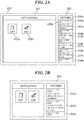
- FIGS. 2A and 2B are views showing examples of the home screen 200 which is displayed on the display 107 in FIG. 1 .
- the home screen 200 is comprised of an application display area 201 and a history display area 203 as shown in FIG. 2A .
- Application buttons 202a and 202b corresponding to respective applications incorporated in the MFP 101 are displayed in the application display area 201.
- the application buttons 202a and 202b are buttons for starting the corresponding applications. For example, when the user selects the application button 202a on the home screen 200, the MFP 101 starts a copy application corresponding to the application button 202a.
- a plurality of history buttons 204a to 204e is displayed in the history display area 203. It should be noted that in the present embodiment, the history buttons 204a to 204e have the same arrangement, which will be described below using the history button 204a as an example.
- the history button 204a is a button for calling job setting information used for a job executed before.
- the setting history includes application information indicating a type of an application that executed the job, job setting information used for the job, and information on a date and time at which the job was executed.
- the MFP 101 generates a history button associated with the stored setting history and displays the generated history button at the top of the history display area 203. Thus, in the present embodiment, dates and times at which job were executed are displayed in order from the newest one in the history display area 203.
- the history button 204a is comprised of a date information display area 205a, an application information display area 206a, and a setting detail display area 207a.
- date information display area 205a date and time information included in a setting history associated with the history button 204a is displayed.
- application information display area 206a application information included in a setting history associated with the history button 204a is displayed. For example, when a setting history associated with the history button 204a is a setting history relating to a copy job, "Copy" which represents the copy application is displayed in the application information display area 206a.
- the setting detail display area 207a information related to job setting information included in a setting history associated with the history button 204a is displayed. For example, setting values of multiple setting items such as settings as to the number of copies, color, zoom rate, sheet-feeding cassette, double-sided printing, and stapling included in job setting information are displayed in the setting detail display area 207a.
- the size of the history button 204a is determined so that all information displayed in the date information display area 205a, the application information display area 206a, and the setting detail display area 207a can be fitted inside the history button 204a. In the present embodiment, the amount of information displayed in the setting detail display area 207a is larger than that of information displayed in the date information display area 205a and the application information display area 206a.
- the amount of information displayed in the setting detail display area 207a in particular has a greater influence on determination as to the size of the history button 204a than the date information display area 205a and the application information display area 206a.
- the history button 204a becomes large along a direction in which the history buttons 204a to 204d are arranged.
- the history button 204a becomes small to such an extent that it is viewable by the user along the direction in which the history button 204a to 204d are arranged.
- the MFP 101 When a history button cannot fit into the history display area 203, only a part of the history button is displayed in the history display area 203 like, for example, the history button 204e.
- the MFP 101 Upon receiving a flick operation upward in a vertical direction of the home screen 200 from the user, the MFP 101 the history buttons in a scrolling manner.
- the MFP 101 displays the whole of the history button 204e, only a part of which has been displayed, and also displays the other history buttons, which have not been displayed in the history display area 203, in the history display area 203.
- the MFP 101 When, for example, the user selects the history button 204a on the home screen 200, the MFP 101 reads out job setting information and application information corresponding to the history button 204a. Then, the MFP 101 sends the job setting information to an application that matches the application information that has been read out. The application that has received the job setting information reads out setting values from the job setting information and displays a setting screen for the application with the read-out setting values set on the setting screen. Thus, the user easily calls setting values that has been configured once.
- the MFP 101 is also able to send stored setting histories to other MFPs and cause these MFPs to display history buttons, which are associated with the setting history, on their displays. On this occasion, by matching display settings such as a character size, the home screen 200 including the same setting history buttons can be displayed on the display of each MFP, and the user can use each MFP with the same ease of operation.
- the display 107 has a limited display area, and hence if display of the history buttons is not controlled suitably for a display size of the display 107, the ease of operation for the user relating to the history buttons may decrease. For example, if all information related to job setting information is displayed in the setting detail display area 207a although the display size of the display 107 is relatively small, the history button 204a would be enlarged. In this case, the number of history buttons displayed at a time on the display 107 would decrease as shown in FIG. 2B , resulting in the ease of operation for the user being decreased.
- the amount of information to be displayed in the setting detail display areas 207a to 207d of the history buttons 204a to 204d is controlled based on the display size of the display 107.
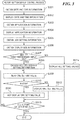
- FIG. 3 is a flowchart showing the procedure of a history button display control process which is carried out by the MFP 101 in FIG. 1 .
- the process in FIG. 3 is implemented by the CPU 103 executing a program stored in the storage area.
- the process in FIG. 3 is also carried out when the setting history described above is stored in the storage area.
- the history button 204a associated with the stored setting history is displayed in the history display area 203.
- the CPU 103 obtains date and time information from the stored setting history (step S301). Next, the CPU 103 displays the obtained date and time information in the date information display area 205a of the history button 204a (step S302). Then, the CPU 103 obtains application information from the stored setting history (step S303). After that, the CPU 103 displays the obtained application information in the application information display area 206a of the history button 204a (step S304). The CPU 103 subsequently obtains job setting information from the stored setting history (step S305). The CPU 103 then obtains display size information on the display 107, which is stored in advance in the storage area (step S306).
- the CPU 103 obtains, for example, a diagonal size of the display 107 as the display size information. After that, based on the obtained display size information, the CPU 103 determines whether or not the display size of the display 107 is smaller than a predetermined display size (step S307). In the step S307, when, for example, the diagonal size is equal to or greater than 10 inches, the CPU 103 determines that the display size of the display 107 is equal to or greater than the predetermined display size. On the other hand, when the diagonal size is smaller than 10 inches, the CPU 103 determines that the display size of the display 107 is smaller than the predetermined display size.
- the CPU 103 obtains factory-shipped setting information stored in the storage area in advance (step S308).
- the factory-shipped setting information includes a plurality of factory-shipped values registered at the time of factory shipment.
- the factory-shipped values are values that cannot be changed by the user.
- the factory-shipped values are used as initial values of job setting information and also used to reset a setting state of the MFP 101.
- initial values of job setting information can be registered as default setting values on a user-by-user basis without using the factory-shipped values.
- the CPU 103 displays a setting screen for this application on the display 107 with the default setting values set on the setting screen.
- the CPU 103 reads out one setting value from the plurality of setting values included in the job setting information (step S309). After that, the CPU 103 identifies a factory-shipped value of a setting item corresponding to the setting value, which was read out in the step 309, from the obtained factory-shipped setting information. The CPU 103 determines whether or not the setting value read out in the step 309 matches the identified factory-shipped value (step S310). Here, when the setting value read out in the step 309 does not match the identified factory-shipped value, it is determined that the setting value is a setting value of a setting item which was changed from an initial value when the user issued an instruction to execute the job.
- the setting value read out in the step 309 matches the identified factory-shipped value, it is determined that the setting value is a setting value of a setting item which was not changed from an initial value when the user issued an instruction to execute the job, that is, an initial value.
- step S310 when the setting value read out in the step 309 matches the identified factory-shipped value, the CPU 103 does not display the setting value in the setting detail display area 207a of the history button 204a (step S311). Then, the CPU 103 carries out a process in step S313, to be described later.
- the CPU 103 displays the setting value in the setting detail display area 207a of the history button 204a (step S312).
- the CPU 103 provides control to reduce the amount of information in the setting detail display area 207a.
- the same control is provided for the setting detail display areas 207b to 207d as well, and the history buttons 204a to 204d are displayed in the history display area 203 in a manner being fitted into it as shown in FIG. 4 .
- the CPU 103 determines whether or not all the setting values included in the job setting information have been read out (step S313).
- the process returns to the step S309.
- the CPU 103 determines in the step S313 that all the setting values included in the job setting information have been read out, the CPU 103 ends the present process.
- the CPU 103 displays all the setting values, which are included in the obtained job setting information, in the setting detail display area 207a of the history button 204a (step S314). After that, the CPU 103 ends the present process.
- the amount of information to be displayed in the setting detail display areas 207a to 207d of the history buttons 204a to 204d is controlled based on the display size of the display 107. Namely, information in an amount unsuitable for the display size of the display 107 is prevented from being displayed in the setting detail display area 207a or the like. It is thus possible to avoid a situation in which the history buttons 204a to 204d cannot be displayed at a time on the display 107 and thus prevent the ease of operation for the user relating to the history buttons 204a to 204d from being decreased.
- the display size of the display 107 when the display size of the display 107 is smaller than the predetermined display size, information on some setting values included in job setting information is displayed in the setting detail display areas 207a to 207d. Namely, when the display size of the display 107 is smaller than the predetermined display size, control is provided to reduce the amount of information to be displayed in the setting detail display areas 207a to 207d so that the history buttons 204a to 204d can fit on the display 107. As a result, even when the display size of the display 107 is smaller than the predetermined display size, the history buttons 204a to 204d can be displayed at a time.
- the determination in the step S307 may be made based on resolution information indicating a resolution of the display 107 obtained as display size information. For example, when the resolution of the display 107 indicated by the obtained resolution information is VGA, the CPU 103 determines that the display size of the display 107 is smaller than the predetermined display size. On the other hand, when the resolution of the display 107 indicated by the obtained resolution information is SVGA, the CPU 103 determines that the display size of the display 107 is equal to or greater than the predetermined display size.
- the determination in the step S307 may be made based on information that is a combination of a resolution and the number of pixels.
- the determination in the step S307 may be made based on identification information and display size mapping information on the display 107 which are stored in advance in the storage area.
- display size information that is a fixed value is stored in the storage area.
- identification information on the display 107 installed in the MFP 101 is stored in the storage area.
- the identification information is, for example, model number information on the display 107.
- the CPU 103 reads out the model number information on the display 107, identifies a display size of the display 107 based on the model information and the display size mapping information, and makes the determination in the step S307 based on the identified display size.
- information on the display 107 connected to the MFP 101 may be received using the touch panel 106 or the like.
- display control for the history buttons may be provided by the CPU 103 executing a display control program that is not created exclusively for the display 107. It should be noted that the display control program is stored in the storage area.
- incorporating a universal display control program, which is not created exclusively for any particular MFP, into a plurality of MFPs equipped with displays of different display sizes is under consideration.
- display of history buttons may not be controlled suitably for a display size of a display.
- Embodiment(s) of the present invention can also be realized by a computer of a system or apparatus that reads out and executes computer executable instructions (e.g., one or more programs) recorded on a storage medium (which may also be referred to more fully as a 'non-transitory computer-readable storage medium') to perform the functions of one or more of the above-described embodiment(s) and/or that includes one or more circuits (e.g., application specific integrated circuit (ASIC)) for performing the functions of one or more of the above-described embodiment(s), and by a method performed by the computer of the system or apparatus by, for example, reading out and executing the computer executable instructions from the storage medium to perform the functions of one or more of the above-described embodiment(s) and/or controlling the one or more circuits to perform the functions of one or more of the above-described embodiment(s).
- computer executable instructions e.g., one or more programs
- a storage medium which may also be referred to more fully as
- the computer may comprise one or more processors (e.g., central processing unit (CPU), micro processing unit (MPU)) and may include a network of separate computers or separate processors to read out and execute the computer executable instructions.
- the computer executable instructions may be provided to the computer, for example, from a network or the storage medium.
- the storage medium may include, for example, one or more of a hard disk, a random-access memory (RAM), a read only memory (ROM), a storage of distributed computing systems, an optical disk (such as a compact disc (CD), digital versatile disc (DVD), or Blu-ray Disc (BD)TM), a flash memory device, a memory card, and the like.
Landscapes
- Engineering & Computer Science (AREA)
- Signal Processing (AREA)
- Multimedia (AREA)
- Theoretical Computer Science (AREA)
- Human Computer Interaction (AREA)
- General Engineering & Computer Science (AREA)
- General Physics & Mathematics (AREA)
- Physics & Mathematics (AREA)
- Computing Systems (AREA)
- Automation & Control Theory (AREA)
- Facsimiles In General (AREA)
- Accessory Devices And Overall Control Thereof (AREA)
- User Interface Of Digital Computer (AREA)
- Control Or Security For Electrophotography (AREA)
Abstract
Description
- The present invention relates to an image processing apparatus, a control method therefor, and a storage medium.
- An MFP (multi-function peripheral) which is an image processing apparatus executing a job based on setting values configured on a job setting screen by a user is known. When the MFP has executed a job, it stores job setting information used for the job (see, for example, Japanese Laid-Open Patent Publication (Kokai) No.
2010-201931 2015-146503 - In a setting information display area that constitutes a history button, information on job setting information associated with the history button is displayed. By seeing the information displayed in the setting information display area, the user easily knows details of settings in the job setting information called when the user selected the history button.
- However, if all information on job setting information is displayed in a setting information display area, the setting information display area would be enlarged, and by extension, a history button would be enlarged. The display unit has a limited display area, and hence a plurality of history buttons cannot be displayed at a time on the display unit, resulting in the ease of operation for the user being decreased.
- The present invention provides an image processing apparatus and a control method therefor, which are capable of preventing the ease of operation for a user relating to history buttons from being decreased, as well as a storage medium.
- Accordingly, a first aspect of the present invention provides an image processing apparatus as specified in claims 1 to 5.
- Accordingly, a second aspect of the present invention provides a control method for an image processing apparatus as specified in claim 6.
- Accordingly, a third aspect of the present invention provides a non-transitory computer-readable storage medium storing a program for causing a computer to execute a control method for an image processing apparatus as specified in claim 7.
- According to the present invention, the ease of operation for a user relating to history buttons is prevented from being decreased.
- Further features of the present invention will become apparent from the following description of exemplary embodiments (with reference to the attached drawings).
-
-
FIG. 1 is a block diagram schematically showing an arrangement of a communication system including an MFP which is an image processing apparatus according to an embodiment of the present invention. -
FIG. 2A and 2B are views showing an example of a home screen which is displayed on a display inFIG. 1 . -
FIG. 3 is a flowchart showing the procedure of a history button display control process which is carried out by the MFP inFIG. 1 . -
FIG. 4 is a view showing an example of a home screen which is displayed on the display inFIG. 1 . - An embodiment of the present invention will now be described in detail with reference to the drawings. It should be noted that in the following description of the present embodiment, the present invention is applied to an MFP which is an image processing apparatus, but the present invention should not always be applied to the MFP. For example, the present invention may be applied to apparatuses capable of displaying history buttons for calling setting information used before, and more specifically, image forming apparatuses such as a printing apparatus, a scanner, a fax, and a digital camera and information processing apparatuses such as a PC and a mobile information terminal.
-
FIG. 1 is a block diagram schematically showing an arrangement of theMFP 101 which is the image processing apparatus according to the embodiment of the present invention. Referring toFIG. 1 , the MFP 101 has acontrol unit 102, atouch panel 106, adisplay 107, anexternal memory 111, ascanner 114, and aprinter 115. Thecontrol unit 102 is connected to thetouch panel 106, thedisplay 107, theexternal memory 111, thescanner 114, and theprinter 115. Thecontrol unit 102 also has aCPU 103, aRAM 104, aROM 105, aninput unit 108, adisplay control unit 109, an external memory I/F 110, and a communication I/F controller 112. TheCPU 103, theRAM 104, theROM 105, theinput unit 108, thedisplay control unit 109, the external memory I/F 110, and the communication I/F controller 112 are connected to one another via asystem bus 116. - The MFP 101 has a plurality of applications for implementing functions such as a copying function, a scanning function, and a data transmission function. The MFP 101 starts the applications to execute jobs based on job setting information configured by a user. The MFP 101 also stores job setting information, which was used for jobs when the jobs were executed, as setting histories, to be described later. The
control unit 102 integratedly controls theentire MFP 101. TheCPU 103 provides various types of control by executing programs stored in, for example, theROM 105 and theexternal memory 111. TheRAM 104, which is a volatile memory, is used as a work area for theCPU 103 and also used as a temporary storage area for each piece of data. TheROM 105, which is a nonvolatile memory, stores image data, programs which are to be executed by theCPU 103, and so forth. In the following description, theRAM 104, theROM 105, and theexternal memory 111 will be correctively referred to as a storage area. - The
touch panel 106 and thedisplay 107 function as an operating unit of the MFP 101. Thetouch panel 106 is configured integrally with thedisplay 107 and attached to an upper layer of a display surface of thedisplay 107. It should be noted that thetouch panel 106 is transparent, and covering the display surface of thedisplay 107 with thetouch panel 106 never interferes with display on thedisplay 107. Input coordinates on thetouch panel 106 are associated with display coordinates on thedisplay 107. Based on a user operation on thetouch panel 106, theinput unit 108 outputs a control signal corresponding to the user operation to theCPU 103. TheCPU 103 controls the constituent elements of the MFP 101 based on the received control signal. Thus, the MFP 101 is able to implement an action according to the user operation. Thedisplay control unit 109 outputs a display signal, which is for displaying an image, to thedisplay 107 based on display control signals received from theCPU 103. Based on a display signal received from thedisplay control unit 109, thedisplay 107 displays, for example, ahome screen 200 inFIG. 2A , to be described later. - The
external memory 111 such as a hard disk, an SSD, a CD, a DVD, or amemory card 111 can be mounted on the external memory I/F 110. The external memory I/F 110, which is controlled by theCPU 103, for example, reads data from and writes data into the mountedexternal memory 111. The communication I/F controller 112, which is controlled by theCPU 103, carries out data communications with an external apparatus which is connected thereto via anetwork 113 such as the Internet, a wired LAN, or a wireless LAN. Thescanner 114 reads an original placed thereon and generates image data based on information that has been read. Theprinter 115 prints image data, which is generated by thescanner 114, or the like on sheets. -
FIGS. 2A and 2B are views showing examples of thehome screen 200 which is displayed on thedisplay 107 inFIG. 1 . Thehome screen 200 is comprised of anapplication display area 201 and ahistory display area 203 as shown inFIG. 2A . -
Application buttons MFP 101 are displayed in theapplication display area 201. Theapplication buttons application button 202a on thehome screen 200, the MFP 101 starts a copy application corresponding to theapplication button 202a. - A plurality of
history buttons 204a to 204e is displayed in thehistory display area 203. It should be noted that in the present embodiment, thehistory buttons 204a to 204e have the same arrangement, which will be described below using thehistory button 204a as an example. Thehistory button 204a is a button for calling job setting information used for a job executed before. When theMFP 101 has executed a job, it stores a setting history for the job in the storage area. The setting history includes application information indicating a type of an application that executed the job, job setting information used for the job, and information on a date and time at which the job was executed. TheMFP 101 generates a history button associated with the stored setting history and displays the generated history button at the top of thehistory display area 203. Thus, in the present embodiment, dates and times at which job were executed are displayed in order from the newest one in thehistory display area 203. - The
history button 204a is comprised of a dateinformation display area 205a, an applicationinformation display area 206a, and a settingdetail display area 207a. In the dateinformation display area 205a, date and time information included in a setting history associated with thehistory button 204a is displayed. In the applicationinformation display area 206a, application information included in a setting history associated with thehistory button 204a is displayed. For example, when a setting history associated with thehistory button 204a is a setting history relating to a copy job, "Copy" which represents the copy application is displayed in the applicationinformation display area 206a. - In the setting
detail display area 207a, information related to job setting information included in a setting history associated with thehistory button 204a is displayed. For example, setting values of multiple setting items such as settings as to the number of copies, color, zoom rate, sheet-feeding cassette, double-sided printing, and stapling included in job setting information are displayed in the settingdetail display area 207a. The size of thehistory button 204a is determined so that all information displayed in the dateinformation display area 205a, the applicationinformation display area 206a, and the settingdetail display area 207a can be fitted inside thehistory button 204a. In the present embodiment, the amount of information displayed in the settingdetail display area 207a is larger than that of information displayed in the dateinformation display area 205a and the applicationinformation display area 206a. For this reason, the amount of information displayed in the settingdetail display area 207a in particular has a greater influence on determination as to the size of thehistory button 204a than the dateinformation display area 205a and the applicationinformation display area 206a. For example, when a large amount of information is to be displayed in the settingdetail display area 207a, thehistory button 204a becomes large along a direction in which thehistory buttons 204a to 204d are arranged. On the other hand, when a small amount of information is to be displayed in the settingdetail display area 207a, thehistory button 204a becomes small to such an extent that it is viewable by the user along the direction in which thehistory button 204a to 204d are arranged. - When a history button cannot fit into the
history display area 203, only a part of the history button is displayed in thehistory display area 203 like, for example, thehistory button 204e. Upon receiving a flick operation upward in a vertical direction of thehome screen 200 from the user, theMFP 101 the history buttons in a scrolling manner. By displaying the history buttons in a scrolling manner, theMFP 101 displays the whole of thehistory button 204e, only a part of which has been displayed, and also displays the other history buttons, which have not been displayed in thehistory display area 203, in thehistory display area 203. - When, for example, the user selects the
history button 204a on thehome screen 200, theMFP 101 reads out job setting information and application information corresponding to thehistory button 204a. Then, theMFP 101 sends the job setting information to an application that matches the application information that has been read out. The application that has received the job setting information reads out setting values from the job setting information and displays a setting screen for the application with the read-out setting values set on the setting screen. Thus, the user easily calls setting values that has been configured once. - The
MFP 101 is also able to send stored setting histories to other MFPs and cause these MFPs to display history buttons, which are associated with the setting history, on their displays. On this occasion, by matching display settings such as a character size, thehome screen 200 including the same setting history buttons can be displayed on the display of each MFP, and the user can use each MFP with the same ease of operation. - The
display 107 has a limited display area, and hence if display of the history buttons is not controlled suitably for a display size of thedisplay 107, the ease of operation for the user relating to the history buttons may decrease. For example, if all information related to job setting information is displayed in the settingdetail display area 207a although the display size of thedisplay 107 is relatively small, thehistory button 204a would be enlarged. In this case, the number of history buttons displayed at a time on thedisplay 107 would decrease as shown inFIG. 2B , resulting in the ease of operation for the user being decreased. - To address this problem, in the present embodiment, the amount of information to be displayed in the setting
detail display areas 207a to 207d of thehistory buttons 204a to 204d is controlled based on the display size of thedisplay 107. -
FIG. 3 is a flowchart showing the procedure of a history button display control process which is carried out by theMFP 101 inFIG. 1 . The process inFIG. 3 is implemented by theCPU 103 executing a program stored in the storage area. The process inFIG. 3 is also carried out when the setting history described above is stored in the storage area. In the process described below, for example, thehistory button 204a associated with the stored setting history is displayed in thehistory display area 203. - Referring to
FIG. 3 , first, theCPU 103 obtains date and time information from the stored setting history (step S301). Next, theCPU 103 displays the obtained date and time information in the dateinformation display area 205a of thehistory button 204a (step S302). Then, theCPU 103 obtains application information from the stored setting history (step S303). After that, theCPU 103 displays the obtained application information in the applicationinformation display area 206a of thehistory button 204a (step S304). TheCPU 103 subsequently obtains job setting information from the stored setting history (step S305). TheCPU 103 then obtains display size information on thedisplay 107, which is stored in advance in the storage area (step S306). TheCPU 103 obtains, for example, a diagonal size of thedisplay 107 as the display size information. After that, based on the obtained display size information, theCPU 103 determines whether or not the display size of thedisplay 107 is smaller than a predetermined display size (step S307). In the step S307, when, for example, the diagonal size is equal to or greater than 10 inches, theCPU 103 determines that the display size of thedisplay 107 is equal to or greater than the predetermined display size. On the other hand, when the diagonal size is smaller than 10 inches, theCPU 103 determines that the display size of thedisplay 107 is smaller than the predetermined display size. - As a result of the determination in the step S307, when the display size of the
display 107 is smaller than the predetermined display size, theCPU 103 obtains factory-shipped setting information stored in the storage area in advance (step S308). The factory-shipped setting information includes a plurality of factory-shipped values registered at the time of factory shipment. The factory-shipped values are values that cannot be changed by the user. The factory-shipped values are used as initial values of job setting information and also used to reset a setting state of theMFP 101. On the other hand, in theMFP 101, initial values of job setting information can be registered as default setting values on a user-by-user basis without using the factory-shipped values. When an application for which a default setting value is set is started, theCPU 103 displays a setting screen for this application on thedisplay 107 with the default setting values set on the setting screen. - Then, the
CPU 103 reads out one setting value from the plurality of setting values included in the job setting information (step S309). After that, theCPU 103 identifies a factory-shipped value of a setting item corresponding to the setting value, which was read out in the step 309, from the obtained factory-shipped setting information. TheCPU 103 determines whether or not the setting value read out in the step 309 matches the identified factory-shipped value (step S310). Here, when the setting value read out in the step 309 does not match the identified factory-shipped value, it is determined that the setting value is a setting value of a setting item which was changed from an initial value when the user issued an instruction to execute the job. On the other hand, when the setting value read out in the step 309 matches the identified factory-shipped value, it is determined that the setting value is a setting value of a setting item which was not changed from an initial value when the user issued an instruction to execute the job, that is, an initial value. - As a result of the determination in the step S310, when the setting value read out in the step 309 matches the identified factory-shipped value, the
CPU 103 does not display the setting value in the settingdetail display area 207a of thehistory button 204a (step S311). Then, theCPU 103 carries out a process in step S313, to be described later. - As a result of the determination in the step S310, when the setting value read out in the step 309 does not match the identified factory-shipped value, the
CPU 103 displays the setting value in the settingdetail display area 207a of thehistory button 204a (step S312). Thus, in the present embodiment, when the display size of thedisplay 107 is smaller than the predetermined display size, theCPU 103 provides control to reduce the amount of information in the settingdetail display area 207a. In this case, the same control is provided for the settingdetail display areas 207b to 207d as well, and thehistory buttons 204a to 204d are displayed in thehistory display area 203 in a manner being fitted into it as shown inFIG. 4 . Then, theCPU 103 determines whether or not all the setting values included in the job setting information have been read out (step S313). - When the
CPU 103 determines in the step S313 that all the setting values included in the job setting information have not been read out, the process returns to the step S309. When theCPU 103 determines in the step S313 that all the setting values included in the job setting information have been read out, theCPU 103 ends the present process. - As a result of the determination in the step S307, when the display size of the
display 107 is equal to or greater than the predetermined display size, theCPU 103 displays all the setting values, which are included in the obtained job setting information, in the settingdetail display area 207a of thehistory button 204a (step S314). After that, theCPU 103 ends the present process. - According to the embodiment described above, the amount of information to be displayed in the setting
detail display areas 207a to 207d of thehistory buttons 204a to 204d is controlled based on the display size of thedisplay 107. Namely, information in an amount unsuitable for the display size of thedisplay 107 is prevented from being displayed in the settingdetail display area 207a or the like. It is thus possible to avoid a situation in which thehistory buttons 204a to 204d cannot be displayed at a time on thedisplay 107 and thus prevent the ease of operation for the user relating to thehistory buttons 204a to 204d from being decreased. - Moreover, in the embodiment described above, when the display size of the
display 107 is smaller than the predetermined display size, information on some setting values included in job setting information is displayed in the settingdetail display areas 207a to 207d. Namely, when the display size of thedisplay 107 is smaller than the predetermined display size, control is provided to reduce the amount of information to be displayed in the settingdetail display areas 207a to 207d so that thehistory buttons 204a to 204d can fit on thedisplay 107. As a result, even when the display size of thedisplay 107 is smaller than the predetermined display size, thehistory buttons 204a to 204d can be displayed at a time. - Furthermore, in the embodiment described above, when the display size of the
display 107 is smaller than the predetermined display size, information on setting values that do not match initial values among a plurality of setting values included in job setting information is displayed in the settingdetail display areas 207a to 207d. Setting values that do not match initial values are very likely to be setting values that were set on purpose by the user when he or she issued an instruction to execute a job, and hence the user pay much attention to those setting values. For this reason, only by seeing setting values that do not match initial values among a plurality of setting values included in job setting information, the user can grasp details of the job setting information to some extent. From the standpoint of letting the user know details of job setting information, it is preferred that information on setting values that do not match initial values is displayed in thehistory buttons 204a to 204d. Accordingly, in the present embodiment, when the display size of thedisplay 107 is smaller than the predetermined display size, information on setting values that do not match initial values among a plurality of setting values included in job setting information is displayed in the settingdetail display areas 207a to 207d. As a result, even when the amount of information to be displayed in the settingdetail display areas 207a to 207d of thehistory buttons 204a to 204d is reduced so that thehistory buttons 204a to 204d can fit on thedisplay 107, the user is informed about details of job setting information associated with thehistory buttons 204a to 204d. - In the embodiment described above, when the display size of the
display 107 is equal to or greater than the predetermined display size, information on all the setting values included in job setting information is displayed in the settingdetail display areas 207a to 207d. This informs the user about full details of job setting information associated with thehistory buttons 204a to 204d and thus provides the user with an environment in which he or she can easily select a desired history button. - It should be noted that the determination in the step S307 may be made based on resolution information indicating a resolution of the
display 107 obtained as display size information. For example, when the resolution of thedisplay 107 indicated by the obtained resolution information is VGA, theCPU 103 determines that the display size of thedisplay 107 is smaller than the predetermined display size. On the other hand, when the resolution of thedisplay 107 indicated by the obtained resolution information is SVGA, theCPU 103 determines that the display size of thedisplay 107 is equal to or greater than the predetermined display size. - Moreover, in the embodiment described above, the determination in the step S307 may be made based on information that is a combination of a resolution and the number of pixels.
- Furthermore, in the embodiment described above, the determination in the step S307 may be made based on identification information and display size mapping information on the
display 107 which are stored in advance in the storage area. When theMFP 101 supports only one display size, display size information that is a fixed value is stored in the storage area. On the other hand, when theMFP 101 supports a plurality of display sizes, identification information on thedisplay 107 installed in theMFP 101 is stored in the storage area. The identification information is, for example, model number information on thedisplay 107. TheCPU 103 reads out the model number information on thedisplay 107, identifies a display size of thedisplay 107 based on the model information and the display size mapping information, and makes the determination in the step S307 based on the identified display size. - In the embodiment described above, information on the
display 107 connected to theMFP 101 may be received using thetouch panel 106 or the like. - Moreover, in the embodiment described above, display control for the history buttons may be provided by the
CPU 103 executing a display control program that is not created exclusively for thedisplay 107. It should be noted that the display control program is stored in the storage area. Here, from the standpoint of making a manufacturing process for an MFP more efficient, incorporating a universal display control program, which is not created exclusively for any particular MFP, into a plurality of MFPs equipped with displays of different display sizes is under consideration. In each of MFPs produced in such a manufacturing process, display of history buttons may not be controlled suitably for a display size of a display. For example, in an MFP equipped with a display of a relatively small display size, only a small number of history buttons can be displayed at a time on the display (see, for example,FIG. 2B ), resulting in the ease of operation for users relating to the history buttons being decreased. The same effects as those in the embodiment described above are obtained by carrying out the process inFIG. 3 described above each of MFPs produced in such a manufacturing process. - Embodiment(s) of the present invention can also be realized by a computer of a system or apparatus that reads out and executes computer executable instructions (e.g., one or more programs) recorded on a storage medium (which may also be referred to more fully as a 'non-transitory computer-readable storage medium') to perform the functions of one or more of the above-described embodiment(s) and/or that includes one or more circuits (e.g., application specific integrated circuit (ASIC)) for performing the functions of one or more of the above-described embodiment(s), and by a method performed by the computer of the system or apparatus by, for example, reading out and executing the computer executable instructions from the storage medium to perform the functions of one or more of the above-described embodiment(s) and/or controlling the one or more circuits to perform the functions of one or more of the above-described embodiment(s). The computer may comprise one or more processors (e.g., central processing unit (CPU), micro processing unit (MPU)) and may include a network of separate computers or separate processors to read out and execute the computer executable instructions. The computer executable instructions may be provided to the computer, for example, from a network or the storage medium. The storage medium may include, for example, one or more of a hard disk, a random-access memory (RAM), a read only memory (ROM), a storage of distributed computing systems, an optical disk (such as a compact disc (CD), digital versatile disc (DVD), or Blu-ray Disc (BD)™), a flash memory device, a memory card, and the like.
- While the present invention has been described with reference to exemplary embodiments, it is to be understood that the invention is not limited to the disclosed exemplary embodiments. The scope of the following claims is to be accorded the broadest interpretation so as to encompass all such modifications and equivalent structures and functions.
Claims (7)
- An image processing apparatus that has a display unit (107), and in response to execution of a function selected by a user, displays on the display unit (107) a history button for calling job setting information used by the function, comprising:a display control unit configured to provide control to display information related to the job setting information in a display area constituting the history button; andan obtaining unit configured to obtain a display size of the display unit (107),wherein based on the display size of the display unit (107), the display control unit controls an amount of information to be displayed in the display area constituting the history button.
- The image processing apparatus according to claim 1, wherein the job setting information includes a plurality of setting values, and
when the display size of the display unit (107) is smaller than a predetermined display size determined in advance, the display control unit displays, in the display area, information on a part of the setting values included in the job setting information. - The image processing apparatus according to claim 2, further comprising a determination unit configured to determine whether or not the setting values included in the job setting information match initial values that are initial values of setting items corresponding to the setting values and registered at the time of factory shipment of the image processing apparatus,
wherein when the display size of the display unit (107) is smaller than the predetermined display size, the display control unit displays, in the display area, information on the setting values that do not match the initial values among the plurality of setting values included in the job setting information. - The image processing apparatus according to claim 2, wherein when the display size of the display unit (107) is equal to or greater than the predetermined display size, the display control unit displays, in the display area, information on all of the setting values included in the job setting information.
- The image processing apparatus according to claim 1, wherein the display control unit controls display based on a display control program that is not created exclusively for the display unit (107).
- A control method for an image processing apparatus that has a display unit (107), and in response to execution of a function selected by a user, displays on the display unit (107) a history button for calling job setting information used by the function, comprising:a display control step of providing control to display information related to the job setting information in a display area constituting the history button; andan obtaining step of obtaining a display size of the display unit (107),wherein in the display control step, an amount of information to be displayed in the display area constituting the history button is controlled based on the display size of the display unit (107).
- A non-transitory computer-readable storage medium storing a program for causing a computer to execute a control method for an image processing apparatus that has a display unit (107), and in response to execution of a function selected by a user, displays on the display unit (107) a history button for calling job setting information used by the function,
the control method for the image processing apparatus comprising:a display control step of providing control to display information related to the job setting information in a display area constituting the history button; andan obtaining step of obtaining a display size of the display unit (107),wherein in the display control step, an amount of information to be displayed in the display area constituting the history button is controlled based on the display size of the display unit (107).
Applications Claiming Priority (1)
| Application Number | Priority Date | Filing Date | Title |
|---|---|---|---|
| JP2018110348A JP6743091B2 (en) | 2018-06-08 | 2018-06-08 | Image processing apparatus, control method thereof, and program |
Publications (2)
| Publication Number | Publication Date |
|---|---|
| EP3579534A1 true EP3579534A1 (en) | 2019-12-11 |
| EP3579534B1 EP3579534B1 (en) | 2021-11-24 |
Family
ID=66770188
Family Applications (1)
| Application Number | Title | Priority Date | Filing Date |
|---|---|---|---|
| EP19178040.2A Not-in-force EP3579534B1 (en) | 2018-06-08 | 2019-06-04 | Image processing apparatus that executes job, control method therefor, and storage medium |
Country Status (6)
| Country | Link |
|---|---|
| US (1) | US11115548B2 (en) |
| EP (1) | EP3579534B1 (en) |
| JP (1) | JP6743091B2 (en) |
| KR (1) | KR102479362B1 (en) |
| CN (1) | CN110580134B (en) |
| BR (1) | BR102019010599A2 (en) |
Families Citing this family (8)
| Publication number | Priority date | Publication date | Assignee | Title |
|---|---|---|---|---|
| JP7210181B2 (en) * | 2018-07-25 | 2023-01-23 | キヤノン株式会社 | Information processing device, its control method, and program |
| EP4083772A4 (en) * | 2019-12-27 | 2023-06-07 | FUJIFILM Corporation | CONTROL DEVICE AND CONTROL PROGRAM |
| US11474756B2 (en) * | 2020-04-21 | 2022-10-18 | Kyocera Document Solutions Inc. | Information processing apparatus capable of allowing display device to display combinations of setting values previously set for each of plurality of functions |
| US11765287B2 (en) * | 2020-04-21 | 2023-09-19 | Kyocera Document Solutions Inc. | Information processing apparatus capable of allowing display device to display combinations of setting values satisfying predetermined condition |
| JP2022102559A (en) | 2020-12-25 | 2022-07-07 | キヤノン株式会社 | Image processing device, display control method and program |
| US20240422272A1 (en) * | 2021-10-29 | 2024-12-19 | Kyocera Corporation | Image processing device |
| JP7748860B2 (en) * | 2021-12-01 | 2025-10-03 | シャープ株式会社 | Image processing device and display control method |
| CN119768278A (en) * | 2022-06-29 | 2025-04-04 | 京瓷株式会社 | Image processing apparatus, control method, and control program |
Citations (6)
| Publication number | Priority date | Publication date | Assignee | Title |
|---|---|---|---|---|
| US20100033748A1 (en) * | 2008-08-07 | 2010-02-11 | Eiji Enami | Image forming apparatus, operation-screen updating method, and computer program product |
| US20100128309A1 (en) * | 2008-11-26 | 2010-05-27 | Canon Kabushiki Kaisha | Image forming apparatus, image forming method, and storage medium storing image forming program thereof |
| JP2010201931A (en) | 2010-04-05 | 2010-09-16 | Canon Inc | Job processing unit, control method of job processing unit, program, and storage medium |
| US20120243016A1 (en) * | 2011-03-25 | 2012-09-27 | Fuji Xerox Co., Ltd. | Controller, image forming apparatus, non-transitory computer readable medium that stores program, and control method |
| US20150222770A1 (en) * | 2014-02-03 | 2015-08-06 | Canon Kabushiki Kaisha | Image processing apparatus, method for controlling image processing apparatus, and storage medium |
| US20170075554A1 (en) * | 2015-09-15 | 2017-03-16 | Ricoh Company, Ltd. | Information processing apparatus and information processing method |
Family Cites Families (12)
| Publication number | Priority date | Publication date | Assignee | Title |
|---|---|---|---|---|
| JP3521047B2 (en) * | 1996-10-18 | 2004-04-19 | ブラザー工業株式会社 | Display control device |
| JP2008018541A (en) * | 2006-07-10 | 2008-01-31 | Konica Minolta Business Technologies Inc | Image forming apparatus, display control method of image forming apparatus and display control program of image forming apparatus |
| JP4452739B2 (en) * | 2007-11-13 | 2010-04-21 | シャープ株式会社 | Information processing system, program, and history information display method |
| JP4569685B2 (en) | 2008-08-13 | 2010-10-27 | コニカミノルタビジネステクノロジーズ株式会社 | Image forming apparatus, address storage method, and address storage program |
| JP4752897B2 (en) * | 2008-10-31 | 2011-08-17 | ソニー株式会社 | Image processing apparatus, image display method, and image display program |
| JP5091267B2 (en) * | 2010-02-18 | 2012-12-05 | シャープ株式会社 | Operating device, electronic device equipped with the operating device, image processing apparatus, and operating method |
| JP6305131B2 (en) * | 2014-03-14 | 2018-04-04 | キヤノン株式会社 | Image processing apparatus, information processing method, and program |
| JP6540059B2 (en) * | 2015-02-03 | 2019-07-10 | コニカミノルタ株式会社 | REMOTE PANEL SYSTEM, REMOTE SCREEN DISPLAY METHOD, AND IMAGE PROCESSING APPARATUS |
| JP6304210B2 (en) * | 2015-12-02 | 2018-04-04 | コニカミノルタ株式会社 | Display device, screen display method, screen display program, and image processing device |
| US20170269896A1 (en) * | 2016-03-21 | 2017-09-21 | I/O Interconnect, Ltd. | Method for Divisionally Displaying Screen Pictures of Multiple Application Pages of Handheld Computer on External Monitor |
| JP6500863B2 (en) * | 2016-09-02 | 2019-04-17 | 京セラドキュメントソリューションズ株式会社 | Image forming device |
| JP2018157504A (en) * | 2017-03-21 | 2018-10-04 | 株式会社リコー | Image processing apparatus and image processing program |
-
2018
- 2018-06-08 JP JP2018110348A patent/JP6743091B2/en not_active Expired - Fee Related
-
2019
- 2019-05-23 KR KR1020190060371A patent/KR102479362B1/en active Active
- 2019-05-23 BR BR102019010599A patent/BR102019010599A2/en unknown
- 2019-06-03 US US16/429,370 patent/US11115548B2/en not_active Expired - Fee Related
- 2019-06-04 CN CN201910480624.0A patent/CN110580134B/en not_active Expired - Fee Related
- 2019-06-04 EP EP19178040.2A patent/EP3579534B1/en not_active Not-in-force
Patent Citations (7)
| Publication number | Priority date | Publication date | Assignee | Title |
|---|---|---|---|---|
| US20100033748A1 (en) * | 2008-08-07 | 2010-02-11 | Eiji Enami | Image forming apparatus, operation-screen updating method, and computer program product |
| US20100128309A1 (en) * | 2008-11-26 | 2010-05-27 | Canon Kabushiki Kaisha | Image forming apparatus, image forming method, and storage medium storing image forming program thereof |
| JP2010201931A (en) | 2010-04-05 | 2010-09-16 | Canon Inc | Job processing unit, control method of job processing unit, program, and storage medium |
| US20120243016A1 (en) * | 2011-03-25 | 2012-09-27 | Fuji Xerox Co., Ltd. | Controller, image forming apparatus, non-transitory computer readable medium that stores program, and control method |
| US20150222770A1 (en) * | 2014-02-03 | 2015-08-06 | Canon Kabushiki Kaisha | Image processing apparatus, method for controlling image processing apparatus, and storage medium |
| JP2015146503A (en) | 2014-02-03 | 2015-08-13 | キヤノン株式会社 | Image processing apparatus, control method of image processing apparatus, and program |
| US20170075554A1 (en) * | 2015-09-15 | 2017-03-16 | Ricoh Company, Ltd. | Information processing apparatus and information processing method |
Also Published As
| Publication number | Publication date |
|---|---|
| EP3579534B1 (en) | 2021-11-24 |
| JP2019209666A (en) | 2019-12-12 |
| CN110580134A (en) | 2019-12-17 |
| KR102479362B1 (en) | 2022-12-20 |
| US20190379799A1 (en) | 2019-12-12 |
| CN110580134B (en) | 2023-11-14 |
| KR20190139762A (en) | 2019-12-18 |
| JP6743091B2 (en) | 2020-08-19 |
| BR102019010599A2 (en) | 2019-12-10 |
| US11115548B2 (en) | 2021-09-07 |
Similar Documents
| Publication | Publication Date | Title |
|---|---|---|
| EP3579534B1 (en) | Image processing apparatus that executes job, control method therefor, and storage medium | |
| US10310793B2 (en) | Image processing system having portable terminal that preregisters a job in an image processing apparatus, image processing apparatus, and portable information terminal | |
| US10165145B2 (en) | Image processing apparatus, method for controlling image processing apparatus, and storage medium | |
| US9288347B2 (en) | Job setting registration device, image processing apparatus, tangible computer-readable recording medium and method for registering job setting | |
| US10853707B2 (en) | Image forming apparatus, control method for image forming apparatus, and storage medium | |
| US10341528B2 (en) | Setting an image forming apparatus as a default device | |
| US9076084B2 (en) | Image forming apparatus having a default mode and method of operating the image forming apparatus | |
| US11252289B2 (en) | Image processing apparatus, information processing method, and storage medium | |
| JP2020068399A (en) | Information processing apparatus, setting control program in information processing apparatus, and setting control method | |
| JP7169847B2 (en) | image forming device | |
| US20200106902A1 (en) | Display device, storage medium storing control program for display device, and method of controlling display device | |
| JP6776753B2 (en) | Processing equipment and image forming equipment | |
| US8848235B2 (en) | Systems and methods for displaying a print preview | |
| JP2005246683A (en) | Image forming apparatus and printing control program | |
| US10609232B2 (en) | Job execution apparatus, method of controlling job execution apparatus, and storage medium job execution apparatus, method of controlling job execution apparatus, and storage medium for setting a setting value | |
| JP6579005B2 (en) | Touch-type input device, image forming apparatus, and control method for touch-type input device | |
| US11412097B2 (en) | Image processing apparatus that displays many apps in selectable manner, control method therefor, and storage medium | |
| JP5969587B2 (en) | Image transmission device | |
| JP6809068B2 (en) | Processing equipment and image forming equipment | |
| US20070229504A1 (en) | Image processing apparatus | |
| JP2022098942A (en) | Information processing device, information processing method, and program | |
| JP2020049678A (en) | Image forming device | |
| JP2018037777A (en) | Image forming apparatus and image forming method | |
| JP2007083427A (en) | Image processor, system and method | |
| JP2011073181A (en) | Image forming apparatus and method for forming image |
Legal Events
| Date | Code | Title | Description |
|---|---|---|---|
| PUAI | Public reference made under article 153(3) epc to a published international application that has entered the european phase |
Free format text: ORIGINAL CODE: 0009012 |
|
| STAA | Information on the status of an ep patent application or granted ep patent |
Free format text: STATUS: THE APPLICATION HAS BEEN PUBLISHED |
|
| AK | Designated contracting states |
Kind code of ref document: A1 Designated state(s): AL AT BE BG CH CY CZ DE DK EE ES FI FR GB GR HR HU IE IS IT LI LT LU LV MC MK MT NL NO PL PT RO RS SE SI SK SM TR |
|
| AX | Request for extension of the european patent |
Extension state: BA ME |
|
| STAA | Information on the status of an ep patent application or granted ep patent |
Free format text: STATUS: REQUEST FOR EXAMINATION WAS MADE |
|
| 17P | Request for examination filed |
Effective date: 20200612 |
|
| RBV | Designated contracting states (corrected) |
Designated state(s): AL AT BE BG CH CY CZ DE DK EE ES FI FR GB GR HR HU IE IS IT LI LT LU LV MC MK MT NL NO PL PT RO RS SE SI SK SM TR |
|
| RIC1 | Information provided on ipc code assigned before grant |
Ipc: H04N 1/00 20060101AFI20210504BHEP |
|
| GRAP | Despatch of communication of intention to grant a patent |
Free format text: ORIGINAL CODE: EPIDOSNIGR1 |
|
| STAA | Information on the status of an ep patent application or granted ep patent |
Free format text: STATUS: GRANT OF PATENT IS INTENDED |
|
| INTG | Intention to grant announced |
Effective date: 20210616 |
|
| GRAS | Grant fee paid |
Free format text: ORIGINAL CODE: EPIDOSNIGR3 |
|
| GRAA | (expected) grant |
Free format text: ORIGINAL CODE: 0009210 |
|
| STAA | Information on the status of an ep patent application or granted ep patent |
Free format text: STATUS: THE PATENT HAS BEEN GRANTED |
|
| RIN1 | Information on inventor provided before grant (corrected) |
Inventor name: SHOGAKI, YOHEI |
|
| AK | Designated contracting states |
Kind code of ref document: B1 Designated state(s): AL AT BE BG CH CY CZ DE DK EE ES FI FR GB GR HR HU IE IS IT LI LT LU LV MC MK MT NL NO PL PT RO RS SE SI SK SM TR |
|
| REG | Reference to a national code |
Ref country code: GB Ref legal event code: FG4D |
|
| RIN1 | Information on inventor provided before grant (corrected) |
Inventor name: SHOGAKI, YOHEI |
|
| REG | Reference to a national code |
Ref country code: AT Ref legal event code: REF Ref document number: 1450761 Country of ref document: AT Kind code of ref document: T Effective date: 20211215 |
|
| REG | Reference to a national code |
Ref country code: DE Ref legal event code: R096 Ref document number: 602019009460 Country of ref document: DE |
|
| REG | Reference to a national code |
Ref country code: IE Ref legal event code: FG4D |
|
| REG | Reference to a national code |
Ref country code: LT Ref legal event code: MG9D |
|
| REG | Reference to a national code |
Ref country code: NL Ref legal event code: MP Effective date: 20211124 |
|
| REG | Reference to a national code |
Ref country code: AT Ref legal event code: MK05 Ref document number: 1450761 Country of ref document: AT Kind code of ref document: T Effective date: 20211124 |
|
| PG25 | Lapsed in a contracting state [announced via postgrant information from national office to epo] |
Ref country code: RS Free format text: LAPSE BECAUSE OF FAILURE TO SUBMIT A TRANSLATION OF THE DESCRIPTION OR TO PAY THE FEE WITHIN THE PRESCRIBED TIME-LIMIT Effective date: 20211124 Ref country code: LT Free format text: LAPSE BECAUSE OF FAILURE TO SUBMIT A TRANSLATION OF THE DESCRIPTION OR TO PAY THE FEE WITHIN THE PRESCRIBED TIME-LIMIT Effective date: 20211124 Ref country code: FI Free format text: LAPSE BECAUSE OF FAILURE TO SUBMIT A TRANSLATION OF THE DESCRIPTION OR TO PAY THE FEE WITHIN THE PRESCRIBED TIME-LIMIT Effective date: 20211124 Ref country code: BG Free format text: LAPSE BECAUSE OF FAILURE TO SUBMIT A TRANSLATION OF THE DESCRIPTION OR TO PAY THE FEE WITHIN THE PRESCRIBED TIME-LIMIT Effective date: 20220224 Ref country code: AT Free format text: LAPSE BECAUSE OF FAILURE TO SUBMIT A TRANSLATION OF THE DESCRIPTION OR TO PAY THE FEE WITHIN THE PRESCRIBED TIME-LIMIT Effective date: 20211124 |
|
| PG25 | Lapsed in a contracting state [announced via postgrant information from national office to epo] |
Ref country code: IS Free format text: LAPSE BECAUSE OF FAILURE TO SUBMIT A TRANSLATION OF THE DESCRIPTION OR TO PAY THE FEE WITHIN THE PRESCRIBED TIME-LIMIT Effective date: 20220324 Ref country code: SE Free format text: LAPSE BECAUSE OF FAILURE TO SUBMIT A TRANSLATION OF THE DESCRIPTION OR TO PAY THE FEE WITHIN THE PRESCRIBED TIME-LIMIT Effective date: 20211124 Ref country code: PT Free format text: LAPSE BECAUSE OF FAILURE TO SUBMIT A TRANSLATION OF THE DESCRIPTION OR TO PAY THE FEE WITHIN THE PRESCRIBED TIME-LIMIT Effective date: 20220324 Ref country code: PL Free format text: LAPSE BECAUSE OF FAILURE TO SUBMIT A TRANSLATION OF THE DESCRIPTION OR TO PAY THE FEE WITHIN THE PRESCRIBED TIME-LIMIT Effective date: 20211124 Ref country code: NO Free format text: LAPSE BECAUSE OF FAILURE TO SUBMIT A TRANSLATION OF THE DESCRIPTION OR TO PAY THE FEE WITHIN THE PRESCRIBED TIME-LIMIT Effective date: 20220224 Ref country code: NL Free format text: LAPSE BECAUSE OF FAILURE TO SUBMIT A TRANSLATION OF THE DESCRIPTION OR TO PAY THE FEE WITHIN THE PRESCRIBED TIME-LIMIT Effective date: 20211124 Ref country code: LV Free format text: LAPSE BECAUSE OF FAILURE TO SUBMIT A TRANSLATION OF THE DESCRIPTION OR TO PAY THE FEE WITHIN THE PRESCRIBED TIME-LIMIT Effective date: 20211124 Ref country code: HR Free format text: LAPSE BECAUSE OF FAILURE TO SUBMIT A TRANSLATION OF THE DESCRIPTION OR TO PAY THE FEE WITHIN THE PRESCRIBED TIME-LIMIT Effective date: 20211124 Ref country code: GR Free format text: LAPSE BECAUSE OF FAILURE TO SUBMIT A TRANSLATION OF THE DESCRIPTION OR TO PAY THE FEE WITHIN THE PRESCRIBED TIME-LIMIT Effective date: 20220225 Ref country code: ES Free format text: LAPSE BECAUSE OF FAILURE TO SUBMIT A TRANSLATION OF THE DESCRIPTION OR TO PAY THE FEE WITHIN THE PRESCRIBED TIME-LIMIT Effective date: 20211124 |
|
| PG25 | Lapsed in a contracting state [announced via postgrant information from national office to epo] |
Ref country code: SM Free format text: LAPSE BECAUSE OF FAILURE TO SUBMIT A TRANSLATION OF THE DESCRIPTION OR TO PAY THE FEE WITHIN THE PRESCRIBED TIME-LIMIT Effective date: 20211124 Ref country code: SK Free format text: LAPSE BECAUSE OF FAILURE TO SUBMIT A TRANSLATION OF THE DESCRIPTION OR TO PAY THE FEE WITHIN THE PRESCRIBED TIME-LIMIT Effective date: 20211124 Ref country code: RO Free format text: LAPSE BECAUSE OF FAILURE TO SUBMIT A TRANSLATION OF THE DESCRIPTION OR TO PAY THE FEE WITHIN THE PRESCRIBED TIME-LIMIT Effective date: 20211124 Ref country code: EE Free format text: LAPSE BECAUSE OF FAILURE TO SUBMIT A TRANSLATION OF THE DESCRIPTION OR TO PAY THE FEE WITHIN THE PRESCRIBED TIME-LIMIT Effective date: 20211124 Ref country code: DK Free format text: LAPSE BECAUSE OF FAILURE TO SUBMIT A TRANSLATION OF THE DESCRIPTION OR TO PAY THE FEE WITHIN THE PRESCRIBED TIME-LIMIT Effective date: 20211124 Ref country code: CZ Free format text: LAPSE BECAUSE OF FAILURE TO SUBMIT A TRANSLATION OF THE DESCRIPTION OR TO PAY THE FEE WITHIN THE PRESCRIBED TIME-LIMIT Effective date: 20211124 |
|
| REG | Reference to a national code |
Ref country code: DE Ref legal event code: R097 Ref document number: 602019009460 Country of ref document: DE |
|
| PLBE | No opposition filed within time limit |
Free format text: ORIGINAL CODE: 0009261 |
|
| STAA | Information on the status of an ep patent application or granted ep patent |
Free format text: STATUS: NO OPPOSITION FILED WITHIN TIME LIMIT |
|
| PG25 | Lapsed in a contracting state [announced via postgrant information from national office to epo] |
Ref country code: AL Free format text: LAPSE BECAUSE OF FAILURE TO SUBMIT A TRANSLATION OF THE DESCRIPTION OR TO PAY THE FEE WITHIN THE PRESCRIBED TIME-LIMIT Effective date: 20211124 |
|
| 26N | No opposition filed |
Effective date: 20220825 |
|
| PG25 | Lapsed in a contracting state [announced via postgrant information from national office to epo] |
Ref country code: SI Free format text: LAPSE BECAUSE OF FAILURE TO SUBMIT A TRANSLATION OF THE DESCRIPTION OR TO PAY THE FEE WITHIN THE PRESCRIBED TIME-LIMIT Effective date: 20211124 |
|
| PG25 | Lapsed in a contracting state [announced via postgrant information from national office to epo] |
Ref country code: MC Free format text: LAPSE BECAUSE OF FAILURE TO SUBMIT A TRANSLATION OF THE DESCRIPTION OR TO PAY THE FEE WITHIN THE PRESCRIBED TIME-LIMIT Effective date: 20211124 |
|
| REG | Reference to a national code |
Ref country code: CH Ref legal event code: PL |
|
| REG | Reference to a national code |
Ref country code: BE Ref legal event code: MM Effective date: 20220630 |
|
| PG25 | Lapsed in a contracting state [announced via postgrant information from national office to epo] |
Ref country code: LU Free format text: LAPSE BECAUSE OF NON-PAYMENT OF DUE FEES Effective date: 20220604 Ref country code: LI Free format text: LAPSE BECAUSE OF NON-PAYMENT OF DUE FEES Effective date: 20220630 Ref country code: IE Free format text: LAPSE BECAUSE OF NON-PAYMENT OF DUE FEES Effective date: 20220604 Ref country code: FR Free format text: LAPSE BECAUSE OF NON-PAYMENT OF DUE FEES Effective date: 20220630 Ref country code: CH Free format text: LAPSE BECAUSE OF NON-PAYMENT OF DUE FEES Effective date: 20220630 |
|
| PG25 | Lapsed in a contracting state [announced via postgrant information from national office to epo] |
Ref country code: IT Free format text: LAPSE BECAUSE OF FAILURE TO SUBMIT A TRANSLATION OF THE DESCRIPTION OR TO PAY THE FEE WITHIN THE PRESCRIBED TIME-LIMIT Effective date: 20211124 Ref country code: BE Free format text: LAPSE BECAUSE OF NON-PAYMENT OF DUE FEES Effective date: 20220630 |
|
| PGFP | Annual fee paid to national office [announced via postgrant information from national office to epo] |
Ref country code: DE Payment date: 20230523 Year of fee payment: 5 |
|
| GBPC | Gb: european patent ceased through non-payment of renewal fee |
Effective date: 20230604 |
|
| PG25 | Lapsed in a contracting state [announced via postgrant information from national office to epo] |
Ref country code: MK Free format text: LAPSE BECAUSE OF FAILURE TO SUBMIT A TRANSLATION OF THE DESCRIPTION OR TO PAY THE FEE WITHIN THE PRESCRIBED TIME-LIMIT Effective date: 20211124 Ref country code: CY Free format text: LAPSE BECAUSE OF FAILURE TO SUBMIT A TRANSLATION OF THE DESCRIPTION OR TO PAY THE FEE WITHIN THE PRESCRIBED TIME-LIMIT Effective date: 20211124 Ref country code: GB Free format text: LAPSE BECAUSE OF NON-PAYMENT OF DUE FEES Effective date: 20230604 |
|
| PG25 | Lapsed in a contracting state [announced via postgrant information from national office to epo] |
Ref country code: HU Free format text: LAPSE BECAUSE OF FAILURE TO SUBMIT A TRANSLATION OF THE DESCRIPTION OR TO PAY THE FEE WITHIN THE PRESCRIBED TIME-LIMIT; INVALID AB INITIO Effective date: 20190604 |
|
| PG25 | Lapsed in a contracting state [announced via postgrant information from national office to epo] |
Ref country code: TR Free format text: LAPSE BECAUSE OF FAILURE TO SUBMIT A TRANSLATION OF THE DESCRIPTION OR TO PAY THE FEE WITHIN THE PRESCRIBED TIME-LIMIT Effective date: 20211124 |
|
| PG25 | Lapsed in a contracting state [announced via postgrant information from national office to epo] |
Ref country code: MT Free format text: LAPSE BECAUSE OF FAILURE TO SUBMIT A TRANSLATION OF THE DESCRIPTION OR TO PAY THE FEE WITHIN THE PRESCRIBED TIME-LIMIT Effective date: 20211124 |
|
| REG | Reference to a national code |
Ref country code: DE Ref legal event code: R119 Ref document number: 602019009460 Country of ref document: DE |
|
| PG25 | Lapsed in a contracting state [announced via postgrant information from national office to epo] |
Ref country code: DE Free format text: LAPSE BECAUSE OF NON-PAYMENT OF DUE FEES Effective date: 20250101 |