EP3579369B1 - Method and arrangement for using hydroelectric power as a power reserve - Google Patents
Method and arrangement for using hydroelectric power as a power reserve Download PDFInfo
- Publication number
- EP3579369B1 EP3579369B1 EP19178478.4A EP19178478A EP3579369B1 EP 3579369 B1 EP3579369 B1 EP 3579369B1 EP 19178478 A EP19178478 A EP 19178478A EP 3579369 B1 EP3579369 B1 EP 3579369B1
- Authority
- EP
- European Patent Office
- Prior art keywords
- output power
- electric energy
- total output
- hydroelectric power
- electricity grid
- Prior art date
- Legal status (The legal status is an assumption and is not a legal conclusion. Google has not performed a legal analysis and makes no representation as to the accuracy of the status listed.)
- Active
Links
- 238000000034 method Methods 0.000 title claims description 32
- 230000005611 electricity Effects 0.000 claims description 85
- 238000004146 energy storage Methods 0.000 claims description 45
- XLYOFNOQVPJJNP-UHFFFAOYSA-N water Substances O XLYOFNOQVPJJNP-UHFFFAOYSA-N 0.000 claims description 26
- 230000008859 change Effects 0.000 claims description 24
- 238000005457 optimization Methods 0.000 claims description 17
- 230000008878 coupling Effects 0.000 claims description 15
- 238000010168 coupling process Methods 0.000 claims description 15
- 238000005859 coupling reaction Methods 0.000 claims description 15
- 238000004422 calculation algorithm Methods 0.000 claims description 14
- 230000008569 process Effects 0.000 claims description 10
- 238000007599 discharging Methods 0.000 claims description 8
- 230000000977 initiatory effect Effects 0.000 claims description 5
- 238000012544 monitoring process Methods 0.000 claims description 5
- 238000006243 chemical reaction Methods 0.000 claims description 4
- 238000001514 detection method Methods 0.000 claims description 4
- 238000009826 distribution Methods 0.000 claims description 4
- 230000004044 response Effects 0.000 claims description 3
- 239000003643 water by type Substances 0.000 description 6
- 230000001276 controlling effect Effects 0.000 description 5
- 230000000694 effects Effects 0.000 description 4
- 238000004519 manufacturing process Methods 0.000 description 4
- 230000001105 regulatory effect Effects 0.000 description 4
- 230000009471 action Effects 0.000 description 3
- 230000033228 biological regulation Effects 0.000 description 3
- 238000004590 computer program Methods 0.000 description 3
- 238000005516 engineering process Methods 0.000 description 3
- 230000007613 environmental effect Effects 0.000 description 3
- 230000008901 benefit Effects 0.000 description 2
- 238000011161 development Methods 0.000 description 2
- 230000018109 developmental process Effects 0.000 description 2
- 238000010586 diagram Methods 0.000 description 2
- ZZUFCTLCJUWOSV-UHFFFAOYSA-N furosemide Chemical compound C1=C(Cl)C(S(=O)(=O)N)=CC(C(O)=O)=C1NCC1=CC=CO1 ZZUFCTLCJUWOSV-UHFFFAOYSA-N 0.000 description 2
- 238000009434 installation Methods 0.000 description 2
- 238000005259 measurement Methods 0.000 description 2
- 238000010248 power generation Methods 0.000 description 2
- 238000003860 storage Methods 0.000 description 2
- 230000007704 transition Effects 0.000 description 2
- 230000003213 activating effect Effects 0.000 description 1
- 230000004913 activation Effects 0.000 description 1
- 238000004458 analytical method Methods 0.000 description 1
- 238000013459 approach Methods 0.000 description 1
- 230000002457 bidirectional effect Effects 0.000 description 1
- 230000005540 biological transmission Effects 0.000 description 1
- 238000004364 calculation method Methods 0.000 description 1
- 239000003990 capacitor Substances 0.000 description 1
- 230000001010 compromised effect Effects 0.000 description 1
- 238000011217 control strategy Methods 0.000 description 1
- 230000007423 decrease Effects 0.000 description 1
- 230000003247 decreasing effect Effects 0.000 description 1
- 230000001934 delay Effects 0.000 description 1
- 230000002074 deregulated effect Effects 0.000 description 1
- 230000008020 evaporation Effects 0.000 description 1
- 238000001704 evaporation Methods 0.000 description 1
- 238000002474 experimental method Methods 0.000 description 1
- 230000009474 immediate action Effects 0.000 description 1
- 238000012423 maintenance Methods 0.000 description 1
- 230000014759 maintenance of location Effects 0.000 description 1
- 238000013178 mathematical model Methods 0.000 description 1
- 230000002085 persistent effect Effects 0.000 description 1
- 238000011160 research Methods 0.000 description 1
- 230000002441 reversible effect Effects 0.000 description 1
- 239000004065 semiconductor Substances 0.000 description 1
Images


Classifications
-
- H—ELECTRICITY
- H02—GENERATION; CONVERSION OR DISTRIBUTION OF ELECTRIC POWER
- H02J—CIRCUIT ARRANGEMENTS OR SYSTEMS FOR SUPPLYING OR DISTRIBUTING ELECTRIC POWER; SYSTEMS FOR STORING ELECTRIC ENERGY
- H02J3/00—Circuit arrangements for ac mains or ac distribution networks
- H02J3/28—Arrangements for balancing of the load in a network by storage of energy
- H02J3/32—Arrangements for balancing of the load in a network by storage of energy using batteries with converting means
-
- F—MECHANICAL ENGINEERING; LIGHTING; HEATING; WEAPONS; BLASTING
- F03—MACHINES OR ENGINES FOR LIQUIDS; WIND, SPRING, OR WEIGHT MOTORS; PRODUCING MECHANICAL POWER OR A REACTIVE PROPULSIVE THRUST, NOT OTHERWISE PROVIDED FOR
- F03B—MACHINES OR ENGINES FOR LIQUIDS
- F03B13/00—Adaptations of machines or engines for special use; Combinations of machines or engines with driving or driven apparatus; Power stations or aggregates
- F03B13/08—Machine or engine aggregates in dams or the like; Conduits therefor, e.g. diffusors
-
- H—ELECTRICITY
- H02—GENERATION; CONVERSION OR DISTRIBUTION OF ELECTRIC POWER
- H02J—CIRCUIT ARRANGEMENTS OR SYSTEMS FOR SUPPLYING OR DISTRIBUTING ELECTRIC POWER; SYSTEMS FOR STORING ELECTRIC ENERGY
- H02J15/00—Systems for storing electric energy
-
- H—ELECTRICITY
- H02—GENERATION; CONVERSION OR DISTRIBUTION OF ELECTRIC POWER
- H02J—CIRCUIT ARRANGEMENTS OR SYSTEMS FOR SUPPLYING OR DISTRIBUTING ELECTRIC POWER; SYSTEMS FOR STORING ELECTRIC ENERGY
- H02J15/00—Systems for storing electric energy
- H02J15/003—Systems for storing electric energy in the form of hydraulic energy
-
- H—ELECTRICITY
- H02—GENERATION; CONVERSION OR DISTRIBUTION OF ELECTRIC POWER
- H02J—CIRCUIT ARRANGEMENTS OR SYSTEMS FOR SUPPLYING OR DISTRIBUTING ELECTRIC POWER; SYSTEMS FOR STORING ELECTRIC ENERGY
- H02J3/00—Circuit arrangements for ac mains or ac distribution networks
- H02J3/38—Arrangements for parallely feeding a single network by two or more generators, converters or transformers
-
- F—MECHANICAL ENGINEERING; LIGHTING; HEATING; WEAPONS; BLASTING
- F05—INDEXING SCHEMES RELATING TO ENGINES OR PUMPS IN VARIOUS SUBCLASSES OF CLASSES F01-F04
- F05B—INDEXING SCHEME RELATING TO WIND, SPRING, WEIGHT, INERTIA OR LIKE MOTORS, TO MACHINES OR ENGINES FOR LIQUIDS COVERED BY SUBCLASSES F03B, F03D AND F03G
- F05B2260/00—Function
- F05B2260/42—Storage of energy
-
- Y—GENERAL TAGGING OF NEW TECHNOLOGICAL DEVELOPMENTS; GENERAL TAGGING OF CROSS-SECTIONAL TECHNOLOGIES SPANNING OVER SEVERAL SECTIONS OF THE IPC; TECHNICAL SUBJECTS COVERED BY FORMER USPC CROSS-REFERENCE ART COLLECTIONS [XRACs] AND DIGESTS
- Y02—TECHNOLOGIES OR APPLICATIONS FOR MITIGATION OR ADAPTATION AGAINST CLIMATE CHANGE
- Y02E—REDUCTION OF GREENHOUSE GAS [GHG] EMISSIONS, RELATED TO ENERGY GENERATION, TRANSMISSION OR DISTRIBUTION
- Y02E10/00—Energy generation through renewable energy sources
- Y02E10/20—Hydro energy
Definitions
- the invention concerns generally the use of power sources to maintain a steady and sufficient supply of electric energy to an electricity grid.
- the invention concerns the optimized use of one or more battery banks together with one or more hydroelectric power plants as power reserves of the grid.
- a high-voltage grid is the geographically distributed backbone of electricity transmission. Power stations supply the grid with electric energy, and at the consuming end are industrial companies, distribution network companies, and ultimately individual households. Losses in the grid sum up with the actual loads to form the total demand of electric power. All users should receive a sufficient amount of electric power at all times, and the AC frequency of the grid should remain as stable as possible. Simultaneously the use of energy sources should be optimized. It is important to maintain a balance between supply and demand in the grid.
- the AC frequency of the grid constitutes a relatively reliable indicator of the balance between supply and demand, so that excessive demand lowers the frequency and vice versa.
- the operator responsible for the grid may decide how various levels of frequency variation will trigger the use of power reserves. For example in a grid the nominal AC frequency of which is 50 Hz, normal operation reserves may be used to maintain the frequency error below 0.2%, i.e. between 49.9 and 50.1 Hz. If the frequency decreases below 49.9 Hz and all normal operation reserves are in use already, disturbance reserves are taken into use.
- Owners of installations with controllable power-generating capability may sell some of this capability to a grid operator for use as a power reserve.
- agile power reserves i.e. ones that can react quickly and flexibly to variations in demand
- This rule in power reserve pricing may have significant economic consequences to the owners of such installations that involve inherent complicat-edness, or other reasons for inherent delays, in controlling the level of produced output power.
- a prior art document EP 2 721 710 A2 describes some approaches for controlling power supplied to an electric grid. Receiving an indication of power to be supplied triggers generating power with a power generator and adjusting, using the generated power, an energy level of an energy storage device to control power supplied to the grid in accordance with the received indication.
- a prior art document DE 10 2011 119 384 B3 describes a hydroelectric power plant which comprises at least one turbine and a generator, to which are coupled a plurality of flywheel storages. Methods for controlling the hydroelectric power plant are also described.
- a particular objective of the invention is that a plurality of hydroelectric power generators could be made to respond to detected changes in demand within a short time.
- a further objective of the invention is that the method and arrangement of the kind described above can be combined with drainage basin optimization in which the available water flows of a drainage basin are used as efficiently as possible within a framework of boundary conditions.
- the objectives of the invention are achieved by combining the rapid use of an electric energy storage to somewhat slower changes made in the total output power level of a plurality of commonly controlled hydroelectric power generators.
- a method according to the invention is characterized by the features recited in the characterizing part of the independent claim directed to a method.
- An arrangement according to the invention is characterized by the features recited in the characterizing part of the independent claim directed to an arrangement.
- a computer program according to the invention comprises one or more sets of one or more machine-executable instructions that, when executed by one or more processors, are configured to cause the performing of a method of the kind described above.
- the computer program may be embodied on a volatile or a nonvolatile computer-readable record medium, for example as a computer program product comprising at least one computer readable non-transitory medium having program code stored thereon.
- Fig. 1 illustrates schematically a first hydroelectric power plant 101 and a second hydroelectric power plant 102 that are located within a common drainage basin. Consequently their hydroelectric power generators draw their operating powers from water flows of the common drainage basin.
- Fig. 1 illustrates a simplified case in which the first 101 and second 102 hydroelectric power plants are located in succession along a single river with no tributaries, so that the upper waters 103, middle waters 104, and lower waters 105 are actually the same water flowing through the system. In a real life drainage basin the water circulation is much more complicated, including tributaries; rainfall; evaporation; agricultural, industrial and municipal use; and other factors. The power plants in question may be located at different parts of the drainage basin, so that the aspects of water circulation affect them differently. This simplified model is sufficient for the following explanation of some basic concepts.
- a hydroelectric power generator comprises a turbine 105, an associated generator 106, and an arrangement of controllable gates 107 and channels 108 that affect the flow of water through the turbine 105.
- a controllable coupling 109 couples the generator 106 to an electricity grid 110.
- One hydroelectric power plant may comprise a plurality of individually controllable hydroelectric power generators. The way in which the hydroelectric power generators supply electric energy to the grid 110 is based on an agreement between the operator of the hydroelectric power plant and the operator of the electricity grid.
- a plurality of hydroelectric power plants within a common drainage basin are run by a common operator.
- a single operator has control over only some of the water flows within the drainage basin: for example, the operator may run a couple of hydroelectric power plants along a main river or river branch of the drainage basin.
- the concept of being located within a common drainage basin is used here to cover all cases where at least some of the same water flows between two or more hydroelectric power generators for which a common operator (or a group of cooperating operators) is responsible.
- An efficiency aim of the operator may be to maximize the amount of electric energy obtainable from hydroelectric power plants within the drainage basin.
- the operator may aim to maximize the total obtainable price of electric energy produced by hydroelectric power plants within the drainage basin.
- Certain natural factors affect these possibilities. For example, the more it rains within the upper parts of the drainage basin, the more water is available for running through the turbines and turning the generators.
- Technical features of the individual hydroelectric power generators constitute another set of boundary conditions within which the operator must try to achieve said aims.
- Drainage system optimization algorithms have been developed that take into account the natural, regulatory, and technical boundary conditions and water flow models within a drainage basin.
- An optimization algorithm of this kind typically tackles a multidimensional numerical optimization problem and looks for obtaining a maximum of a value function (or a minimum of a penalty function). It may take measurement data from various parts of the system as initial values and experiment with parameter values that represent possible actions of the operator. Those actions that seem to maximize the value function are performed, and the calculations are constantly repeated so that any changes in the initial values and/or boundary conditions can be taken dynamically into account.
- the AC frequency of the electricity grid 110 is an important indicator of the balance between supply and demand of electric energy.
- the AC frequency is at a nominal value like 50 Hz or 60 Hz.
- Increasing demand tends to lower the AC frequency, while a momentary surplus of supply tends to increase it.
- the operator of the electricity grid 110 has set a default frequency range within which the AC frequency may vary. Deviations from the default frequency range necessitate the activation of reserves. A frequency drop of certain magnitude must be met by activating more production capacity and/or by lowering the consumption of certain large, controllable loads.
- some production capacity must be decoupled and/or the consumption of energy in controllable loads must be increased.
- the owner of a power reserve may receive significant monetary advantage from the operator of the electricity grid by committing to maintaining a certain amount of power reserve and to putting it into use as agreed at the occurrence of a frequency deviation.
- Some changes in the AC frequency of the electricity grid 110 may come suddenly and unexpectedly, for example when a major power plant must be suddenly closed down or decoupled from the electricity grid due to unexpected technical problems.
- Power reserves are the more valuable, the faster they can react to such sudden and unexpected changes. Fastest changes that may come into consideration should take place essentially immediately, or within seconds at the most.
- Hydroelectric power has not been considered a viable choice for use as a fast-reacting power reserve because of the natural tardiness in controlling the amount of produced power. If a drop is observed in the AC frequency of an electricity grid and a command is consequently given to a hydroelectric power generator to increase power, what physically happens is that one or more gates are opened more, in order to make more water flow through the turbine.
- the gates are heavy structures the moving of which takes some time. Also it takes some time for the "additional" water to accelerate into the required flow speed, and it takes time for the rotating mass in the turbine and generator to acquire the new rotating speed.
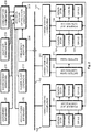
- Fig. 2 illustrates an arrangement with which hydroelectric power can be used as a power reserve of an electricity grid.
- the arrangement of fig. 2 comprises a plurality of hydroelectric power generators coupled to supply electric energy to an electricity grid 110.
- the hydroelectric power generators are located in two separate hydroelectric power plants 101 and 102.
- An example of a hydroelectric power generator is the hydroelectric power generator of the first hydroelectric power plant 101, comprising a turbine 105, an associated generator 106, and gates 107 for affecting the flow of water through the turbine 105.
- the arrangement of fig. 2 comprises an electric energy storage, which can be called a battery bank 201 for short.
- a battery bank 201 for short.
- This short designation is used here for convenience, but it does not limit the actual technical implementation of the electric energy storage.
- the technology of the electric energy storage may involve elements of e.g. capacitors of various kinds, including but not being limited to supercapacitors.
- the arrangement comprises also a controllable coupling 202 between the battery bank 201 and the electricity grid 110.
- the controllable coupling 202 may be a bidirectional coupling, so that it can be made to allow electric energy to flow in both directions between the battery bank 201 and the electricity grid 110.
- the controllable coupling 202 may comprise controllable switching components, as well as components needed to match the battery bank 201 and the electricity grid 110 electrically to each other.
- the controllable coupling 202 may comprise an inverter for converting DC power taken from the battery bank 201 to AC power before feeding it into the electricity grid 110.
- the controllable coupling 202 may comprise a rectifier for converting AC power taken from the electricity grid 110 to DC power before feeding it into the battery bank 202.
- a battery bank controller 203 is shown separately in fig. 2 , configured to control the battery bank 201 as well as the controllable coupling 202 between the battery bank 201 and the electricity grid 110.
- the controller functionality may also be partly or wholly integral with the battery bank 201 and/or the controllable coupling 202.
- the arrangement of fig. 2 comprises a frequency monitor 204 that is configured to monitor an AC frequency of the electricity grid 110.
- a control system 205 is coupled to receive detection information from the frequency monitor 204 and configured to control, through the respective power plant controllers 206 and 207, a total output power level at which the hydroelectric power generators supply electric power to the electric grid 110.
- the control system 205 is also configured to control, through the battery bank controller 203, the controllable coupling 202 between the battery bank 201 and the electricity grid 110.
- the concept of a frequency monitor can be considered more generally, so that the actual device that physically monitors the AC frequency of the electricity grid 110 does not need to be an explicit part of the arrangement. Rather, the act of physically monitoring the AC frequency of the electricity grid 110 may take place somewhere else, at the responsibility of someone else, who then delivers the results of such monitoring in real time or essentially real time to those parties that have committed to maintaining power reserves.
- the frequency monitor 204 in the arrangement of fig. 2 can be considered to be the responding device that is responsible for receiving the results of actual frequency monitoring from a device that physically monitors the frequency somewhere else.
- the control system 205 is configured to take into account a number of other aspects than just the AC frequency of the electricity grid 110 in making the controlling decisions.
- fig. 2 shows a consumption forecaster 208, a weather forecaster 209, various environment monitors 210, geography databases 211, regulations databases 212, and power plant logbooks 213.
- the consumption forecaster 209 is configured to follow the consumption of electric energy from the electric grid 110 and to predict, how the consumption of electric energy will develop in the near future.
- the weather forecaster 209 is configured to follow developments in weather to predict, how weather conditions such as rainfall will affect the possibilities of producing electric energy in the hydroelectric power generators.
- Environment monitors 210 may comprise various monitors such as water level sensors, wind sensors, temperature sensors, and others. They may provide the control system 205 with up-to-date initial values indicative of environmental parameters within the drainage basin. The control system 205 may store various time series of readings that have been obtained from the environment monitors 210, so that is has history data from which it can make analyses of how environmental conditions have developed.
- the geography databases 211 contain information about the geography of the drainage basin, which is useful in simulating the future developments in environmental conditions as well as simulating the effects of the way in which water will flow through the various hydroelectric power plants within the drainage basin.
- the geography databases 211 may contain also time series of observed water flows within various parts of the drainage basin.
- Regulations databases 212 contain information about the regulatory boundary conditions that must not be compromised. Other information that may be included in the regulations databases 212 are for example time series of energy prices, history data about the pricing of power reserves, and the like. "Soft" regulatory limits can be included, like recommendations about how recreational use of the lakes and rivers should be taken into account, and/or how water levels and water flows affect the nature within the drainage basin.
- Power plant logbooks 213 provide the control system 205 with technical boundary conditions, including but not being limited to factors such as capacity, efficiency profiles, availability, and maintenance schedules of the various hydroelectric power generators that the control system 205 may control.
- the possibility of using the arrangement of fig. 2 as a fast power reserve of the electricity grid 110 is based on the fact that the controllable coupling 202 can be activated essentially instantaneously to make electric energy flow between the battery bank 201 and the electricity grid 110.
- the control system 205 receives from the frequency monitor 204 detection information indicative of a frequency drop, i.e. a deviation of the AC frequency of the electricity grid 110 from the default frequency range in the decreasing direction.
- a frequency drop means that more electric energy is momentarily consumed than produced.
- the control system 205 may command, through the battery bank controller 203, the battery bank 201 to feed additional electric energy to the electric grid 110.
- solid-state (i.e. semiconductor) technology is used in the controllable coupling 202, changing the way in which electric energy flows between the battery bank 201 and the electricity grid 110 does not involve any moving parts and can be accomplished through giving appropriate values for the required electronic control signals.
- the control system 205 may initiate a change in the total output power of the plurality of hydroelectric power generators it has at its disposal. Again assuming for the time being that the detected deviation of the AC frequency of the grid was a frequency drop, the control system 205 may initiate a change from a first total output power level to a second, higher output power level. Above it was explained how such a change cannot take place instantaneously in hydroelectric power generation but involves certain inevitable physical facts that make it take some time.
- the control system 205 is configured to continue to make electric energy flow between the battery bank 201 and the electricity grid for the duration of time it takes for the total output power of said plurality of hydroelectric power generators to reach said second total output power level.
- the rate at which the total output power level can be made to change may be in the order of a megawatt per minute or somewhat more or less. It can be for example about 0.8 megawatts per minute.
- control system 205 may know, how much time it takes to execute the desired change in total output power and what kind of a profile the change will follow. Additionally or alternatively the control system 205 may receive feedback measurements from the power plant controllers 206 and 207, the feedback being dynamically indicative of the momentary output power of each hydroelectric power generator. The control system 205 may dynamically control the power at which electric energy flows between the battery bank 201 and the electricity grid, at each moment to correspond to a remaining difference between a momentary output power of the plurality of hydroelectric power generators and the second total output power level. This way the sum of the electric power taken from the battery bank and the electric power produced by the plurality of hydroelectric power generators remains constant.
- the step of making electric energy flow between an electric energy storage (the battery bank 201) and the electricity grid 110 now involves using electric energy drawn from the electricity grid 110 to charge the battery bank 201.
- the step of initiating a change in the total output power of the plurality of hydroelectric power generators means a change from a first total output power level to a second, lower total output power level.
- the step of detecting a deviation from a default frequency range may be given some further consideration.
- the most straightforward case is one where the detecting of a deviation comprises detecting an actual, occurred deviation, in which a measured AC frequency of the electricity grid 110 is out of its default frequency range. Additionally or alternatively the principle of predictive detecting can be applied.
- Said detecting of a deviation may comprise detecting a so-called imminent deviation, in which a measured AC frequency of said electricity grid exhibits a trend that, if continued, leads to said measured AC frequency of said electricity grid going out of said default frequency range.
- a drainage system optimization algorithm when decisions are made about the respective output power levels of the hydroelectric power generators and about the changes to be made in them.
- An advantageous place where such a drainage system optimization algorithm may be executed in the system architecture of fig. 2 is the control system 205; it is for this reason the control system 205 is labeled a drainage system optimization computer in fig. 2 .
- the drainage system optimization algorithm may aim at optimizing an amount of electric energy obtainable from hydroelectric power plants within said drainage basin.
- the drainage system optimization algorithm may aim at optimizing factors like: a total obtainable price of electric energy produced by hydroelectric power plants within said drainage basin; a total efficiency of the hydroelectric power generators; minimal need of mechanical movements of gates; reactions to icing and other causes of screen losses; distribution in time of produced electric energy, for example in terms of the period of production plans; and so on.
- the desired output power level of the plurality of hydroelectric power generators is a quite decisive aim for the control system 205 to achieve and maintain.
- this can be achieved for example by penalizing heavily any deviation between the actual and desired total output power levels, so that when the optimization algorithm tries to find a maximum of the value function it would prefer making decisions that bring the actual total output power level very close to the desired total output power level. Cases may occur, however, where from the optimization viewpoint it is even more desirable to achieve some other aim, at the cost of not reaching the desired total output power level.
- at least one of the first and second total output power levels mentioned above may be selected on the basis of executing the drainage system optimization algorithm, running the plurality of hydroelectric power generators at the corresponding total output power level is not a mandatory requirement.
- This so-called default state of charge can be selected on the basis of certain assumptions about what the battery bank 201 will be mostly used for. If the probabilities of frequency drops and frequency overshoots in the electricity grid 110 are equal, and if an equal absolute amount of electric energy should assumedly flow between the battery bank 201 and the electricity grid 110 in each case, the default state of charge may be 50% of the effective capacity of the battery bank 201. Other selections are possible. For example, one half of the effective capacity might be reserved for use as a disturbance reserve, which will only be used to counteract frequency drops that are larger than a predetermined limit set by the operator of the electric grid.
- the other half of the effective capacity of the battery bank could be reserved for use as a normal operating reserve, which will be used to counteract both smaller frequency drops and frequency overshoots.
- the default state of charge may be 75% of the effective capacity of the battery bank 201.
- the invention is configured to first "exaggerate" the change slightly, and only thereafter bring the total output power level to the actual desired value.
- said total output power of said plurality of hydroelectric power generators is made to continue changing in the same direction. This continuing change lasts until a second, later moment of time.
- the total output power of the plurality of hydroelectric power generators is made to return to said second total output power level at a third, even later moment of time.
- the battery bank is recharged if it was discharging before said first moment of time, or discharged if it was charging before said first moment of time.
- the battery bank 201 and its associated controllable coupling 202 may react extremely fast to a detected deviation from the default frequency range. Together with the fact that the battery bank 201 may be capable of temporarily meeting the occurred need of supplying more power or draining excess power all by itself, this can be used so that shortest deviations from the default frequency range are counteracted with the battery bank only, without making any changes to the total output power level of the plurality of hydroelectric power generators.
- the control system 205 may first make electric energy flow between the electric grid 110 and the battery bank 201 and then wait for a short duration of time to see, whether the AC frequency of the grid will recover sufficiently.
- the method explained here may comprise continuing to monitor the AC frequency of the electricity grid 110 to detect, whether the deviation from the default frequency persists.
- the change in the total output power of the plurality of hydroelectric power generators from a first total output power level to a second total output power level is then initiated only if said deviation from said default frequency range is found to persist.
- the method may comprise executing an energy storage restoration process in order to bring the battery bank back into its default state of charge.
- the electric energy storage restoration process may comprise reciprocal changes in the total output power of the plurality of hydroelectric power generators and the power at which electric energy flows between the electric energy storage and the electricity grid, until a target charge level of said electric energy storage has been reached.
- a frequency drop was first detected and the battery bank 201 was consequently made to feed electric energy into the grid 110.
- the frequency drop was found not to persist, so the total output power level would not need to be changed to meet any additional demand of power.
- the total output power level is increased anyway, in order to generate the amount of electric energy that is needed to replenish the battery bank 201 and bring it back to its default state of charge.
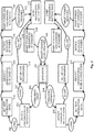
- Fig. 3 illustrates an embodiment of a method in the form of a state diagram.
- each of the plurality of hydroelectric power generators is run at its respective output power level to supply electric energy at a total output power to the electricity grid.
- the wait state 301 comprises also monitoring the AC frequency of the electricity grid to detect deviations from a default frequency range.
- Figs. 4 and 5 illustrate power levels in two alternative cases that both refer to a detected frequency drop.
- the control system will wait for a while to examine whether the deviation persists before making a decision to change a total output power level of the plurality of hydroelectric power generators.
- Fig. 4 concerns a case in which the deviation was found to persist ("long" deviation 306 in fig. 3 )
- fig. 5 concerns a case in which the deviation was found not to persist (“short" deviation 307 in fig. 3 ).
- the upper curve represents the total output power of the plurality of hydroelectric power generators
- the lower curve represents the power at which electric energy flows between the electric energy storage and the electricity grid.
- the units are arbitrary and only used for illustrative purposes.
- Moment A in fig. 4 is the moment at which the frequency drop is detected. Between moments A and B the battery bank feeds power into the electric grid at the power of +2 units while the control system continues to monitor the AC frequency of the electricity grid to detect, whether the frequency drop persists. This happens to be the case, so following the condition "long" 306 in fig. 3 the control system proceeds to set a new total power output level at state 308 and to identify at state 309 that hydroelectric power generator (or those hydroelectric power generators) that will be used to generate the required additional electric power.
- the control system initiates a change in the total output power of said plurality of hydroelectric power generators from a first total output power level of 8 units to a second total output power level of 10 units: the upper curve in fig. 4 turns upwards. Initiating the increase in total output power corresponds to state 310 in fig. 3 . Simultaneously the control system begins to reduce the power at which electric energy is fed from the battery bank to the electricity grid: the lower curve in fig. 4 turns downwards.
- Changing the two powers in concert means that between moments B and C in fig. 4 the sum of electric powers fed into the electricity grid from the plurality of hydroelectric power generators on one hand and the battery bank on the other hand remains constant.
- the power at which electric energy flows between said electric energy storage and said electricity grid is dynamically controlled to correspond to a remaining difference between a momentary output power of said plurality of hydroelectric power generators and said second total output power level.
- Fig. 5 illustrates changes in power when the deviation (which is detected at moment F in fig. 5 ) is found not to persist.
- this is the condition "short" 307.
- the control system finds that the AC frequency of the network is safely within the default frequency range again, so no changes in the total output power of the plurality of hydroelectric power generations are needed, and the battery bank can be decoupled from the electricity grid. However, the electric energy that was taken from the battery bank between moments F and G should be replenished. Therefore the control system makes plans for an energy storage restoration process, as illustrated by state 316 in fig. 3 . Since there are now no particular needs to react fast, the planned energy storage restoration process can begin at any suitable moment in the near future, and it may follow a profile that comprises only very smooth changes in power, if necessary.
- the lower part of the state diagram in fig. 3 is essentially a mirror image of the upper part, with all frequency- and power-related terms inverted.
- state 309 comprised identifying that hydroelectric power generator or those hydroelectric power generators that were to be sped up
- the corresponding mirror image state 317 comprises identifying that hydroelectric power generator or those hydroelectric power generators that are to be slowed down.
- Fig. 6 is an example of such a combination. What happens at moments A, B, and C is the same as in fig. 4 : a frequency drop is detected at moment A, the deviation is found to persist at moment B, and the initial change in the total output power of the plurality of hydroelectric power generators is completed at moment C. However, at moment L a large frequency overshoot is suddenly detected, necessitating immediate action to cut the amount of electric power fed into the electricity grid.
- the power at which electric energy flows from the electricity grid to the battery bank is dynamically controlled to correspond to a remaining difference between a momentary output power of said plurality of hydroelectric power generators and the 8 units total output power level, until at moment M it is noticed that some additional recharging of the battery bank must still be done in order to replenish all energy that was taken between moments A and C. Therefore both curves level out between moments M and N, and ramp to their final values in concert between moments N and O.
Landscapes
- Engineering & Computer Science (AREA)
- Power Engineering (AREA)
- Chemical & Material Sciences (AREA)
- Combustion & Propulsion (AREA)
- Mechanical Engineering (AREA)
- General Engineering & Computer Science (AREA)
- Control Of Eletrric Generators (AREA)
- Supply And Distribution Of Alternating Current (AREA)
Priority Applications (1)
| Application Number | Priority Date | Filing Date | Title |
|---|---|---|---|
| EP21208478.4A EP4002635A1 (en) | 2018-06-06 | 2019-06-05 | Method and arrangement for using hydroelectric power as a power reserve |
Applications Claiming Priority (1)
| Application Number | Priority Date | Filing Date | Title |
|---|---|---|---|
| FI20185518A FI130474B (sv) | 2018-06-06 | 2018-06-06 | Förfarande och arrangemang för att använda vattenkraft som effektreserv |
Related Child Applications (1)
| Application Number | Title | Priority Date | Filing Date |
|---|---|---|---|
| EP21208478.4A Division EP4002635A1 (en) | 2018-06-06 | 2019-06-05 | Method and arrangement for using hydroelectric power as a power reserve |
Publications (2)
| Publication Number | Publication Date |
|---|---|
| EP3579369A1 EP3579369A1 (en) | 2019-12-11 |
| EP3579369B1 true EP3579369B1 (en) | 2021-11-17 |
Family
ID=66770375
Family Applications (2)
| Application Number | Title | Priority Date | Filing Date |
|---|---|---|---|
| EP21208478.4A Pending EP4002635A1 (en) | 2018-06-06 | 2019-06-05 | Method and arrangement for using hydroelectric power as a power reserve |
| EP19178478.4A Active EP3579369B1 (en) | 2018-06-06 | 2019-06-05 | Method and arrangement for using hydroelectric power as a power reserve |
Family Applications Before (1)
| Application Number | Title | Priority Date | Filing Date |
|---|---|---|---|
| EP21208478.4A Pending EP4002635A1 (en) | 2018-06-06 | 2019-06-05 | Method and arrangement for using hydroelectric power as a power reserve |
Country Status (3)
| Country | Link |
|---|---|
| EP (2) | EP4002635A1 (sv) |
| ES (1) | ES2906848T3 (sv) |
| FI (1) | FI130474B (sv) |
Families Citing this family (3)
| Publication number | Priority date | Publication date | Assignee | Title |
|---|---|---|---|---|
| US11070061B2 (en) * | 2019-10-04 | 2021-07-20 | AES Gener S.A. | Virtual reservoir storing energy for a hydroelectric power plant |
| FR3112038B1 (fr) | 2020-06-30 | 2022-06-03 | Inst Supergrid | Système de production d'électricité comprenant une turbine hydraulique, avec une réponse dynamique améliorée |
| CN112882398B (zh) * | 2021-01-26 | 2022-10-21 | 四川华能宝兴河水电有限责任公司 | 一种水电站总控自动化仿真模拟系统 |
Family Cites Families (2)
| Publication number | Priority date | Publication date | Assignee | Title |
|---|---|---|---|---|
| DK2721710T3 (da) * | 2011-06-20 | 2018-01-29 | The Aes Corp | Hybridgeneratorkraftværk, der anvender en kombination af tidstro genereringsindretninger og et energilagringssystem. |
| DE102011119384B3 (de) * | 2011-11-25 | 2013-03-28 | Voith Patent Gmbh | Wasserkraftwerk und Verfahren zu Primärregelung eines Wasserkraftwerks |
-
2018
- 2018-06-06 FI FI20185518A patent/FI130474B/sv active
-
2019
- 2019-06-05 ES ES19178478T patent/ES2906848T3/es active Active
- 2019-06-05 EP EP21208478.4A patent/EP4002635A1/en active Pending
- 2019-06-05 EP EP19178478.4A patent/EP3579369B1/en active Active
Non-Patent Citations (1)
| Title |
|---|
| None * |
Also Published As
| Publication number | Publication date |
|---|---|
| EP4002635A1 (en) | 2022-05-25 |
| ES2906848T3 (es) | 2022-04-20 |
| EP3579369A1 (en) | 2019-12-11 |
| FI130474B (sv) | 2023-09-25 |
| FI20185518A1 (sv) | 2019-12-07 |
Similar Documents
| Publication | Publication Date | Title |
|---|---|---|
| Golshani et al. | Coordination of wind farm and pumped-storage hydro for a self-healing power grid | |
| EP3579369B1 (en) | Method and arrangement for using hydroelectric power as a power reserve | |
| CN103825304B (zh) | 控制电力网的方法 | |
| Jiang et al. | Energy management of microgrid in grid-connected and stand-alone modes | |
| Qi et al. | Distributed supervisory predictive control of distributed wind and solar energy systems | |
| US8493030B2 (en) | Method for operating an energy storage system | |
| US20170262007A1 (en) | Multi-agent oriented method for forecasting-based control with load priority of microgrid in island mode | |
| CN106489221A (zh) | 服务器装置的功率管理 | |
| US20160011618A1 (en) | Server installation as a grid condition sensor | |
| CN105684257A (zh) | 用于控制微电网的操作的微电网能量管理系统和方法 | |
| CN112381375B (zh) | 一种基于潮流分配矩阵的电网经济运行域快速生成方法 | |
| Nassourou et al. | Economic model predictive control for energy dispatch of a smart micro-grid system | |
| Sun et al. | Improving the restorability of bulk power systems with the implementation of a WF-BESS system | |
| KR102391449B1 (ko) | 독립운전 시 수소설비가 있는 전력 커뮤니티를 위한 에너지 제어 시스템 | |
| Shoeb et al. | A multilayer preventive control to regulate voltage and frequency in autonomous microgrids | |
| Elkholy et al. | A resilient and intelligent multi-objective energy management for a hydrogen-battery hybrid energy storage system based on MFO technique | |
| US10074984B2 (en) | Electric power control system | |
| CN115733146A (zh) | 一种源荷储多时间尺度协调调度模型 | |
| Pratama et al. | Operational Road Map in North Sulawesi and Gorontalo Power Grid Considering the Intermittent Photovoltaic Penetration | |
| Mindra et al. | Combined peak shaving/time shifting strategy for microgrid controlled renewable energy efficiency optimization | |
| KR20140042208A (ko) | 조건 예측 시스템과 발전 제어 시스템을 연계한 조력발전 설비 및 그 운전 제어 방법 | |
| Qi et al. | Coordinated Scheduling of Micro-grid Combined Heat and Power Based on Dynamic Feedback Correction and Virtual Penalty Cost | |
| Qiu | Planning and Operation of Energy Storage Systems in Power Systems | |
| Saleh et al. | Solving Unit Commitment Including Wind Power Generation Using PSS® E | |
| Wang | Energy management for islanded microgrid with energy storage systems |
Legal Events
| Date | Code | Title | Description |
|---|---|---|---|
| PUAI | Public reference made under article 153(3) epc to a published international application that has entered the european phase |
Free format text: ORIGINAL CODE: 0009012 |
|
| STAA | Information on the status of an ep patent application or granted ep patent |
Free format text: STATUS: THE APPLICATION HAS BEEN PUBLISHED |
|
| AK | Designated contracting states |
Kind code of ref document: A1 Designated state(s): AL AT BE BG CH CY CZ DE DK EE ES FI FR GB GR HR HU IE IS IT LI LT LU LV MC MK MT NL NO PL PT RO RS SE SI SK SM TR |
|
| AX | Request for extension of the european patent |
Extension state: BA ME |
|
| STAA | Information on the status of an ep patent application or granted ep patent |
Free format text: STATUS: REQUEST FOR EXAMINATION WAS MADE |
|
| 17P | Request for examination filed |
Effective date: 20200604 |
|
| RBV | Designated contracting states (corrected) |
Designated state(s): AL AT BE BG CH CY CZ DE DK EE ES FI FR GB GR HR HU IE IS IT LI LT LU LV MC MK MT NL NO PL PT RO RS SE SI SK SM TR |
|
| STAA | Information on the status of an ep patent application or granted ep patent |
Free format text: STATUS: EXAMINATION IS IN PROGRESS |
|
| 17Q | First examination report despatched |
Effective date: 20200818 |
|
| STAA | Information on the status of an ep patent application or granted ep patent |
Free format text: STATUS: EXAMINATION IS IN PROGRESS |
|
| GRAP | Despatch of communication of intention to grant a patent |
Free format text: ORIGINAL CODE: EPIDOSNIGR1 |
|
| STAA | Information on the status of an ep patent application or granted ep patent |
Free format text: STATUS: GRANT OF PATENT IS INTENDED |
|
| INTG | Intention to grant announced |
Effective date: 20210616 |
|
| GRAS | Grant fee paid |
Free format text: ORIGINAL CODE: EPIDOSNIGR3 |
|
| GRAA | (expected) grant |
Free format text: ORIGINAL CODE: 0009210 |
|
| STAA | Information on the status of an ep patent application or granted ep patent |
Free format text: STATUS: THE PATENT HAS BEEN GRANTED |
|
| AK | Designated contracting states |
Kind code of ref document: B1 Designated state(s): AL AT BE BG CH CY CZ DE DK EE ES FI FR GB GR HR HU IE IS IT LI LT LU LV MC MK MT NL NO PL PT RO RS SE SI SK SM TR |
|
| REG | Reference to a national code |
Ref country code: GB Ref legal event code: FG4D |
|
| REG | Reference to a national code |
Ref country code: IE Ref legal event code: FG4D |
|
| REG | Reference to a national code |
Ref country code: DE Ref legal event code: R096 Ref document number: 602019009293 Country of ref document: DE |
|
| REG | Reference to a national code |
Ref country code: AT Ref legal event code: REF Ref document number: 1448841 Country of ref document: AT Kind code of ref document: T Effective date: 20211215 |
|
| REG | Reference to a national code |
Ref country code: FI Ref legal event code: FGE |
|
| REG | Reference to a national code |
Ref country code: NO Ref legal event code: T2 Effective date: 20211117 |
|
| REG | Reference to a national code |
Ref country code: SE Ref legal event code: TRGR |
|
| REG | Reference to a national code |
Ref country code: LT Ref legal event code: MG9D |
|
| REG | Reference to a national code |
Ref country code: NL Ref legal event code: MP Effective date: 20211117 |
|
| REG | Reference to a national code |
Ref country code: ES Ref legal event code: FG2A Ref document number: 2906848 Country of ref document: ES Kind code of ref document: T3 Effective date: 20220420 |
|
| PG25 | Lapsed in a contracting state [announced via postgrant information from national office to epo] |
Ref country code: RS Free format text: LAPSE BECAUSE OF FAILURE TO SUBMIT A TRANSLATION OF THE DESCRIPTION OR TO PAY THE FEE WITHIN THE PRESCRIBED TIME-LIMIT Effective date: 20211117 Ref country code: LT Free format text: LAPSE BECAUSE OF FAILURE TO SUBMIT A TRANSLATION OF THE DESCRIPTION OR TO PAY THE FEE WITHIN THE PRESCRIBED TIME-LIMIT Effective date: 20211117 Ref country code: BG Free format text: LAPSE BECAUSE OF FAILURE TO SUBMIT A TRANSLATION OF THE DESCRIPTION OR TO PAY THE FEE WITHIN THE PRESCRIBED TIME-LIMIT Effective date: 20220217 |
|
| PG25 | Lapsed in a contracting state [announced via postgrant information from national office to epo] |
Ref country code: IS Free format text: LAPSE BECAUSE OF FAILURE TO SUBMIT A TRANSLATION OF THE DESCRIPTION OR TO PAY THE FEE WITHIN THE PRESCRIBED TIME-LIMIT Effective date: 20220317 Ref country code: PT Free format text: LAPSE BECAUSE OF FAILURE TO SUBMIT A TRANSLATION OF THE DESCRIPTION OR TO PAY THE FEE WITHIN THE PRESCRIBED TIME-LIMIT Effective date: 20220317 Ref country code: PL Free format text: LAPSE BECAUSE OF FAILURE TO SUBMIT A TRANSLATION OF THE DESCRIPTION OR TO PAY THE FEE WITHIN THE PRESCRIBED TIME-LIMIT Effective date: 20211117 Ref country code: NL Free format text: LAPSE BECAUSE OF FAILURE TO SUBMIT A TRANSLATION OF THE DESCRIPTION OR TO PAY THE FEE WITHIN THE PRESCRIBED TIME-LIMIT Effective date: 20211117 Ref country code: LV Free format text: LAPSE BECAUSE OF FAILURE TO SUBMIT A TRANSLATION OF THE DESCRIPTION OR TO PAY THE FEE WITHIN THE PRESCRIBED TIME-LIMIT Effective date: 20211117 Ref country code: HR Free format text: LAPSE BECAUSE OF FAILURE TO SUBMIT A TRANSLATION OF THE DESCRIPTION OR TO PAY THE FEE WITHIN THE PRESCRIBED TIME-LIMIT Effective date: 20211117 Ref country code: GR Free format text: LAPSE BECAUSE OF FAILURE TO SUBMIT A TRANSLATION OF THE DESCRIPTION OR TO PAY THE FEE WITHIN THE PRESCRIBED TIME-LIMIT Effective date: 20220218 |
|
| PG25 | Lapsed in a contracting state [announced via postgrant information from national office to epo] |
Ref country code: SM Free format text: LAPSE BECAUSE OF FAILURE TO SUBMIT A TRANSLATION OF THE DESCRIPTION OR TO PAY THE FEE WITHIN THE PRESCRIBED TIME-LIMIT Effective date: 20211117 Ref country code: SK Free format text: LAPSE BECAUSE OF FAILURE TO SUBMIT A TRANSLATION OF THE DESCRIPTION OR TO PAY THE FEE WITHIN THE PRESCRIBED TIME-LIMIT Effective date: 20211117 Ref country code: RO Free format text: LAPSE BECAUSE OF FAILURE TO SUBMIT A TRANSLATION OF THE DESCRIPTION OR TO PAY THE FEE WITHIN THE PRESCRIBED TIME-LIMIT Effective date: 20211117 Ref country code: EE Free format text: LAPSE BECAUSE OF FAILURE TO SUBMIT A TRANSLATION OF THE DESCRIPTION OR TO PAY THE FEE WITHIN THE PRESCRIBED TIME-LIMIT Effective date: 20211117 Ref country code: DK Free format text: LAPSE BECAUSE OF FAILURE TO SUBMIT A TRANSLATION OF THE DESCRIPTION OR TO PAY THE FEE WITHIN THE PRESCRIBED TIME-LIMIT Effective date: 20211117 Ref country code: CZ Free format text: LAPSE BECAUSE OF FAILURE TO SUBMIT A TRANSLATION OF THE DESCRIPTION OR TO PAY THE FEE WITHIN THE PRESCRIBED TIME-LIMIT Effective date: 20211117 |
|
| REG | Reference to a national code |
Ref country code: DE Ref legal event code: R097 Ref document number: 602019009293 Country of ref document: DE |
|
| PLBE | No opposition filed within time limit |
Free format text: ORIGINAL CODE: 0009261 |
|
| STAA | Information on the status of an ep patent application or granted ep patent |
Free format text: STATUS: NO OPPOSITION FILED WITHIN TIME LIMIT |
|
| 26N | No opposition filed |
Effective date: 20220818 |
|
| PG25 | Lapsed in a contracting state [announced via postgrant information from national office to epo] |
Ref country code: AL Free format text: LAPSE BECAUSE OF FAILURE TO SUBMIT A TRANSLATION OF THE DESCRIPTION OR TO PAY THE FEE WITHIN THE PRESCRIBED TIME-LIMIT Effective date: 20211117 |
|
| PG25 | Lapsed in a contracting state [announced via postgrant information from national office to epo] |
Ref country code: SI Free format text: LAPSE BECAUSE OF FAILURE TO SUBMIT A TRANSLATION OF THE DESCRIPTION OR TO PAY THE FEE WITHIN THE PRESCRIBED TIME-LIMIT Effective date: 20211117 |
|
| PG25 | Lapsed in a contracting state [announced via postgrant information from national office to epo] |
Ref country code: MC Free format text: LAPSE BECAUSE OF FAILURE TO SUBMIT A TRANSLATION OF THE DESCRIPTION OR TO PAY THE FEE WITHIN THE PRESCRIBED TIME-LIMIT Effective date: 20211117 |
|
| REG | Reference to a national code |
Ref country code: AT Ref legal event code: UEP Ref document number: 1448841 Country of ref document: AT Kind code of ref document: T Effective date: 20211117 |
|
| REG | Reference to a national code |
Ref country code: BE Ref legal event code: MM Effective date: 20220630 |
|
| PG25 | Lapsed in a contracting state [announced via postgrant information from national office to epo] |
Ref country code: IE Free format text: LAPSE BECAUSE OF NON-PAYMENT OF DUE FEES Effective date: 20220605 |
|
| PG25 | Lapsed in a contracting state [announced via postgrant information from national office to epo] |
Ref country code: BE Free format text: LAPSE BECAUSE OF NON-PAYMENT OF DUE FEES Effective date: 20220630 |
|
| P01 | Opt-out of the competence of the unified patent court (upc) registered |
Effective date: 20230529 |
|
| PGFP | Annual fee paid to national office [announced via postgrant information from national office to epo] |
Ref country code: NO Payment date: 20230628 Year of fee payment: 5 Ref country code: FR Payment date: 20230626 Year of fee payment: 5 Ref country code: DE Payment date: 20230626 Year of fee payment: 5 |
|
| PGFP | Annual fee paid to national office [announced via postgrant information from national office to epo] |
Ref country code: SE Payment date: 20230627 Year of fee payment: 5 Ref country code: LU Payment date: 20230627 Year of fee payment: 5 Ref country code: FI Payment date: 20230626 Year of fee payment: 5 |
|
| PGFP | Annual fee paid to national office [announced via postgrant information from national office to epo] |
Ref country code: IT Payment date: 20230620 Year of fee payment: 5 Ref country code: ES Payment date: 20230703 Year of fee payment: 5 Ref country code: CH Payment date: 20230702 Year of fee payment: 5 |
|
| GBPC | Gb: european patent ceased through non-payment of renewal fee |
Effective date: 20230605 |
|
| PG25 | Lapsed in a contracting state [announced via postgrant information from national office to epo] |
Ref country code: MK Free format text: LAPSE BECAUSE OF FAILURE TO SUBMIT A TRANSLATION OF THE DESCRIPTION OR TO PAY THE FEE WITHIN THE PRESCRIBED TIME-LIMIT Effective date: 20211117 Ref country code: CY Free format text: LAPSE BECAUSE OF FAILURE TO SUBMIT A TRANSLATION OF THE DESCRIPTION OR TO PAY THE FEE WITHIN THE PRESCRIBED TIME-LIMIT Effective date: 20211117 Ref country code: GB Free format text: LAPSE BECAUSE OF NON-PAYMENT OF DUE FEES Effective date: 20230605 |