EP3579359A1 - Fiber laser system and method for controlling same - Google Patents
Fiber laser system and method for controlling same Download PDFInfo
- Publication number
- EP3579359A1 EP3579359A1 EP18748105.6A EP18748105A EP3579359A1 EP 3579359 A1 EP3579359 A1 EP 3579359A1 EP 18748105 A EP18748105 A EP 18748105A EP 3579359 A1 EP3579359 A1 EP 3579359A1
- Authority
- EP
- European Patent Office
- Prior art keywords
- fiber laser
- fiber
- power
- excitation
- laser
- Prior art date
- Legal status (The legal status is an assumption and is not a legal conclusion. Google has not performed a legal analysis and makes no representation as to the accuracy of the status listed.)
- Pending
Links
- 239000000835 fiber Substances 0.000 title claims abstract description 295
- 238000000034 method Methods 0.000 title claims description 45
- 230000005284 excitation Effects 0.000 claims abstract description 197
- 230000002457 bidirectional effect Effects 0.000 claims description 45
- 239000013307 optical fiber Substances 0.000 description 14
- 230000007257 malfunction Effects 0.000 description 12
- 230000010355 oscillation Effects 0.000 description 9
- 102100024513 F-box only protein 6 Human genes 0.000 description 8
- 101001052796 Homo sapiens F-box only protein 6 Proteins 0.000 description 8
- 102100022116 F-box only protein 2 Human genes 0.000 description 6
- 101000824158 Homo sapiens F-box only protein 2 Proteins 0.000 description 6
- 238000001069 Raman spectroscopy Methods 0.000 description 6
- 238000005259 measurement Methods 0.000 description 4
- 230000002093 peripheral effect Effects 0.000 description 4
- FFBHFFJDDLITSX-UHFFFAOYSA-N benzyl N-[2-hydroxy-4-(3-oxomorpholin-4-yl)phenyl]carbamate Chemical compound OC1=C(NC(=O)OCC2=CC=CC=C2)C=CC(=C1)N1CCOCC1=O FFBHFFJDDLITSX-UHFFFAOYSA-N 0.000 description 3
- 230000006866 deterioration Effects 0.000 description 3
- 238000006243 chemical reaction Methods 0.000 description 2
- 238000010586 diagram Methods 0.000 description 2
- 239000000463 material Substances 0.000 description 2
- 229910052761 rare earth metal Inorganic materials 0.000 description 2
- 230000000694 effects Effects 0.000 description 1
- 230000004927 fusion Effects 0.000 description 1
- 238000004904 shortening Methods 0.000 description 1
Images


Classifications
-
- H—ELECTRICITY
- H01—ELECTRIC ELEMENTS
- H01S—DEVICES USING THE PROCESS OF LIGHT AMPLIFICATION BY STIMULATED EMISSION OF RADIATION [LASER] TO AMPLIFY OR GENERATE LIGHT; DEVICES USING STIMULATED EMISSION OF ELECTROMAGNETIC RADIATION IN WAVE RANGES OTHER THAN OPTICAL
- H01S3/00—Lasers, i.e. devices using stimulated emission of electromagnetic radiation in the infrared, visible or ultraviolet wave range
- H01S3/09—Processes or apparatus for excitation, e.g. pumping
- H01S3/091—Processes or apparatus for excitation, e.g. pumping using optical pumping
- H01S3/094—Processes or apparatus for excitation, e.g. pumping using optical pumping by coherent light
- H01S3/094003—Processes or apparatus for excitation, e.g. pumping using optical pumping by coherent light the pumped medium being a fibre
- H01S3/094011—Processes or apparatus for excitation, e.g. pumping using optical pumping by coherent light the pumped medium being a fibre with bidirectional pumping, i.e. with injection of the pump light from both two ends of the fibre
-
- H—ELECTRICITY
- H01—ELECTRIC ELEMENTS
- H01S—DEVICES USING THE PROCESS OF LIGHT AMPLIFICATION BY STIMULATED EMISSION OF RADIATION [LASER] TO AMPLIFY OR GENERATE LIGHT; DEVICES USING STIMULATED EMISSION OF ELECTROMAGNETIC RADIATION IN WAVE RANGES OTHER THAN OPTICAL
- H01S3/00—Lasers, i.e. devices using stimulated emission of electromagnetic radiation in the infrared, visible or ultraviolet wave range
- H01S3/05—Construction or shape of optical resonators; Accommodation of active medium therein; Shape of active medium
- H01S3/06—Construction or shape of active medium
- H01S3/063—Waveguide lasers, i.e. whereby the dimensions of the waveguide are of the order of the light wavelength
- H01S3/067—Fibre lasers
-
- B—PERFORMING OPERATIONS; TRANSPORTING
- B23—MACHINE TOOLS; METAL-WORKING NOT OTHERWISE PROVIDED FOR
- B23K—SOLDERING OR UNSOLDERING; WELDING; CLADDING OR PLATING BY SOLDERING OR WELDING; CUTTING BY APPLYING HEAT LOCALLY, e.g. FLAME CUTTING; WORKING BY LASER BEAM
- B23K26/00—Working by laser beam, e.g. welding, cutting or boring
- B23K26/02—Positioning or observing the workpiece, e.g. with respect to the point of impact; Aligning, aiming or focusing the laser beam
- B23K26/06—Shaping the laser beam, e.g. by masks or multi-focusing
- B23K26/062—Shaping the laser beam, e.g. by masks or multi-focusing by direct control of the laser beam
-
- H—ELECTRICITY
- H01—ELECTRIC ELEMENTS
- H01S—DEVICES USING THE PROCESS OF LIGHT AMPLIFICATION BY STIMULATED EMISSION OF RADIATION [LASER] TO AMPLIFY OR GENERATE LIGHT; DEVICES USING STIMULATED EMISSION OF ELECTROMAGNETIC RADIATION IN WAVE RANGES OTHER THAN OPTICAL
- H01S3/00—Lasers, i.e. devices using stimulated emission of electromagnetic radiation in the infrared, visible or ultraviolet wave range
- H01S3/10—Controlling the intensity, frequency, phase, polarisation or direction of the emitted radiation, e.g. switching, gating, modulating or demodulating
- H01S3/102—Controlling the intensity, frequency, phase, polarisation or direction of the emitted radiation, e.g. switching, gating, modulating or demodulating by controlling the active medium, e.g. by controlling the processes or apparatus for excitation
-
- H—ELECTRICITY
- H01—ELECTRIC ELEMENTS
- H01S—DEVICES USING THE PROCESS OF LIGHT AMPLIFICATION BY STIMULATED EMISSION OF RADIATION [LASER] TO AMPLIFY OR GENERATE LIGHT; DEVICES USING STIMULATED EMISSION OF ELECTROMAGNETIC RADIATION IN WAVE RANGES OTHER THAN OPTICAL
- H01S3/00—Lasers, i.e. devices using stimulated emission of electromagnetic radiation in the infrared, visible or ultraviolet wave range
- H01S3/10—Controlling the intensity, frequency, phase, polarisation or direction of the emitted radiation, e.g. switching, gating, modulating or demodulating
- H01S3/13—Stabilisation of laser output parameters, e.g. frequency or amplitude
- H01S3/131—Stabilisation of laser output parameters, e.g. frequency or amplitude by controlling the active medium, e.g. by controlling the processes or apparatus for excitation
- H01S3/1312—Stabilisation of laser output parameters, e.g. frequency or amplitude by controlling the active medium, e.g. by controlling the processes or apparatus for excitation by controlling the optical pumping
-
- H—ELECTRICITY
- H01—ELECTRIC ELEMENTS
- H01S—DEVICES USING THE PROCESS OF LIGHT AMPLIFICATION BY STIMULATED EMISSION OF RADIATION [LASER] TO AMPLIFY OR GENERATE LIGHT; DEVICES USING STIMULATED EMISSION OF ELECTROMAGNETIC RADIATION IN WAVE RANGES OTHER THAN OPTICAL
- H01S2301/00—Functional characteristics
- H01S2301/03—Suppression of nonlinear conversion, e.g. specific design to suppress for example stimulated brillouin scattering [SBS], mainly in optical fibres in combination with multimode pumping
-
- H—ELECTRICITY
- H01—ELECTRIC ELEMENTS
- H01S—DEVICES USING THE PROCESS OF LIGHT AMPLIFICATION BY STIMULATED EMISSION OF RADIATION [LASER] TO AMPLIFY OR GENERATE LIGHT; DEVICES USING STIMULATED EMISSION OF ELECTROMAGNETIC RADIATION IN WAVE RANGES OTHER THAN OPTICAL
- H01S3/00—Lasers, i.e. devices using stimulated emission of electromagnetic radiation in the infrared, visible or ultraviolet wave range
- H01S3/05—Construction or shape of optical resonators; Accommodation of active medium therein; Shape of active medium
- H01S3/06—Construction or shape of active medium
- H01S3/063—Waveguide lasers, i.e. whereby the dimensions of the waveguide are of the order of the light wavelength
- H01S3/067—Fibre lasers
- H01S3/0675—Resonators including a grating structure, e.g. distributed Bragg reflectors [DBR] or distributed feedback [DFB] fibre lasers
-
- H—ELECTRICITY
- H01—ELECTRIC ELEMENTS
- H01S—DEVICES USING THE PROCESS OF LIGHT AMPLIFICATION BY STIMULATED EMISSION OF RADIATION [LASER] TO AMPLIFY OR GENERATE LIGHT; DEVICES USING STIMULATED EMISSION OF ELECTROMAGNETIC RADIATION IN WAVE RANGES OTHER THAN OPTICAL
- H01S3/00—Lasers, i.e. devices using stimulated emission of electromagnetic radiation in the infrared, visible or ultraviolet wave range
- H01S3/09—Processes or apparatus for excitation, e.g. pumping
- H01S3/091—Processes or apparatus for excitation, e.g. pumping using optical pumping
- H01S3/094—Processes or apparatus for excitation, e.g. pumping using optical pumping by coherent light
- H01S3/0941—Processes or apparatus for excitation, e.g. pumping using optical pumping by coherent light of a laser diode
- H01S3/09415—Processes or apparatus for excitation, e.g. pumping using optical pumping by coherent light of a laser diode the pumping beam being parallel to the lasing mode of the pumped medium, e.g. end-pumping
-
- H—ELECTRICITY
- H01—ELECTRIC ELEMENTS
- H01S—DEVICES USING THE PROCESS OF LIGHT AMPLIFICATION BY STIMULATED EMISSION OF RADIATION [LASER] TO AMPLIFY OR GENERATE LIGHT; DEVICES USING STIMULATED EMISSION OF ELECTROMAGNETIC RADIATION IN WAVE RANGES OTHER THAN OPTICAL
- H01S3/00—Lasers, i.e. devices using stimulated emission of electromagnetic radiation in the infrared, visible or ultraviolet wave range
- H01S3/10—Controlling the intensity, frequency, phase, polarisation or direction of the emitted radiation, e.g. switching, gating, modulating or demodulating
- H01S3/10069—Memorized or pre-programmed characteristics, e.g. look-up table [LUT]
-
- H—ELECTRICITY
- H01—ELECTRIC ELEMENTS
- H01S—DEVICES USING THE PROCESS OF LIGHT AMPLIFICATION BY STIMULATED EMISSION OF RADIATION [LASER] TO AMPLIFY OR GENERATE LIGHT; DEVICES USING STIMULATED EMISSION OF ELECTROMAGNETIC RADIATION IN WAVE RANGES OTHER THAN OPTICAL
- H01S3/00—Lasers, i.e. devices using stimulated emission of electromagnetic radiation in the infrared, visible or ultraviolet wave range
- H01S3/23—Arrangements of two or more lasers not provided for in groups H01S3/02 - H01S3/22, e.g. tandem arrangements of separate active media
- H01S3/2383—Parallel arrangements
Definitions
- the present invention relates to a fiber laser system including a fiber laser group including at least one bidirectional excitation fiber laser.
- the present invention also relates to a method for controlling such a fiber laser system.
- processing target object laser light reflected from an object which is being processed
- Stimulated Raman scattering can be considered a process of power conversion from laser light to Stokes light. It is known that a greater conversion efficiency (Raman gain) of Stimulated Raman scattering causes Stokes oscillation to more easily occur, so that an oscillation state of each fiber laser may be made unstable or a malfunction may occur in each fiber laser (see Patent Literature 1).
- Patent Literature 1 Japanese Patent Application Publication, Tokukai, No. 2015-95641 A (Publication Date: May 18, 2015 )
- a ratio of (a) a Stokes light power included in a forward output power to (b) a laser light power included in a backward output power serves as an index indicating difficulty in occurrence of Stokes oscillation (hereinafter also referred to as "reflection resistance").
- a laser light power included in a backward output power and a Stokes light power included in a forward output power are a laser light power and a Stokes light power, respectively, each of which has been measured while all fiber lasers are caused to be in rated operation.
- a higher ratio between the laser light power and the Stokes light power causes Stokes oscillation to more easily occur. This results in a low reflection resistance.
- a lower ratio between the laser light power and the Stokes light power causes Stokes oscillation to less easily occur. This results in a high reflection resistance.
- fiber lasers may vary in reflection resistance.
- a fiber laser system as a whole deteriorates in reflection resistance by being strongly affected by a fiber laser which has a low reflection resistance.
- Stokes oscillation occurs in a fiber laser which has a low reflection resistance
- Stokes light which has been generated by that fiber laser causes Stokes oscillation to occur also in a fiber laser which has a high reflection resistance.
- a reflection resistance of a fiber laser system as a whole be restored by increasing a reflection resistance of a fiber laser which has a low reflection resistance.
- fiber lasers vary in reflection resistance in, for example, a case where a malfunction occurs in a laser diode which is provided in a fiber laser so as to serve as an excitation light source.
- a fiber laser system including three fiber lasers is to be discussed. It is assumed that each of the fiber lasers includes six laser diodes. According to the fiber laser system, in a case where any one of the laser diodes malfunctions in any one of the fiber lasers, a sum of excitation light powers obtained in the fiber lasers comes to 17/18 times an output obtained in a case where none of the laser diodes malfunction in the fiber lasers, and the fiber laser system has a lower output power accordingly.
- the fiber laser system carries out control so as to maintain its output power. Then, a power of excitation light of a fiber laser including a laser diode in which a malfunction occurs comes to 5/6 ⁇ 18/17( ⁇ 1) times the power which had been obtained before the malfunction occurred, whereas a power of excitation light of a fiber laser including no laser diode in which a malfunction occurs comes to 6/6 ⁇ 18/17(>1) times the power which had been obtained before the malfunction occurred.
- a fiber laser having a great excitation light power i.e., a fiber laser including no laser diode in which a malfunction occurs has a lower reflection resistance.
- the present invention has been made in view of the problems, and an object of the present invention is to achieve a fiber laser system which is capable of, in a case where fiber lasers vary in reflection resistance, restoring a reflection resistance of the fiber laser system as a whole while maintaining an output power of the fiber laser system as a whole.
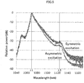
- Fig. 5 is a graph showing wavelength dependency of a relative power of light which is outputted by a bidirectional excitation fiber laser (a power measured at a lasing wavelength ⁇ L of laser light is assumed to be 1).
- a comparison between relative powers measured at a wavelength ⁇ S of Stokes light shows that a relative power obtained in a case where asymmetric excitation is carried out is smaller by approximately 5 dB than a relative power obtained in a case where symmetric excitation is carried out.
- a fiber laser system in accordance with an aspect of the present invention includes: a fiber laser group including at least one bidirectional excitation fiber laser; and a control section configured to increase a proportion of a backward excitation light power in the at least one bidirectional excitation fiber laser so that fiber lasers constituting the fiber laser group less vary in reflection resistance.
- a control method in accordance with an aspect of the present invention is a method for controlling a fiber laser system including a fiber laser group including at least one bidirectional excitation fiber laser, the method including the step of: increasing a proportion of a backward excitation light power in the at least one bidirectional excitation fiber laser so that fiber lasers constituting the fiber laser group less vary in reflection resistance.
- An aspect of the present invention makes it possible to achieve a fiber laser system which is capable of, in a case where fiber lasers vary in reflection resistance, restoring a reflection resistance of the fiber laser system as a whole while maintaining an output power of the fiber laser system as a whole.
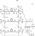
- Fig. 1 is a block diagram illustrating a configuration of the fiber laser system FLS.
- the fiber laser FLi which is a bidirectional excitation fiber laser, serve as a laser source configured to generate laser light.
- the fiber laser FLi is connected to a corresponding one of input ports of the laser combiner LC. Laser light generated by the fiber laser FLi is supplied to the laser combiner LC via a corresponding input port.
- the laser combiner LC combines together waves of laser light generated by the respective fiber lasers FL1 through FLn, so that combined laser light is obtained.
- the laser combiner LC has an output port which is connected to an input end of the delivery fiber DF. The combined laser light thus obtained in the laser combiner LC is supplied to the delivery fiber DF.
- the delivery fiber DF guides the combined laser light thus obtained in the laser combiner LC.
- the delivery fiber DF has an exit end which is connected to the processing head H. Light which has been guided through the delivery fiber DF is emitted through the processing head H to a processing target object W.
- the fiber laser system FLS further includes laser power monitors LM1 through LMn, Stokes power monitors SM1 through SMn, and the control section C.
- Laser power monitors LMi each measure a laser light power PLi included in a backward output power of a corresponding fiber laser FLi.
- a laser power monitor LMi can be configured to include, for example, (i) a filter configured to selectively let through light in a band including a lasing wavelength of a fiber laser FLi (a band including no Stokes wavelength (described later)) and (ii) a power measuring device configured to measure a power of light which has been let through the filter.
- the laser power monitor LMi can be a power measuring device (Rayleigh monitor) configured to measure a power of Rayleigh scattering light which is generated by an optical fiber which guides a backward output power of a corresponding fiber laser FLi.
- the laser power monitor LMi can alternatively be a power measuring device (leaking light monitor) configured to measure a power of light having leaked from a fusion splice point at which an optical fiber which guides a backward output power of a corresponding fiber laser FLi are fusion-spliced.
- a measurement result obtained in the laser power monitor LMi is supplied to the control section C.
- a Stokes power monitor SMi each measure a Stokes light power PSi included in a forward output power of a corresponding fiber laser FLi.
- a Stokes power monitor SMi can be configured to include, for example, (i) a filter configured to selectively let through light in a band including a Stokes wavelength of a fiber laser FLi (a band including no lasing wavelength (described earlier)) and (ii) a power measuring device configured to measure a power of light which has been let through the filter.
- a Stokes wavelength of a fiber laser FLi refers to a wavelength obtained by adding, to a lasing wavelength of that fiber laser FLi, a wavelength corresponding to a Raman shift.
- a measurement result obtained in the Stokes power monitor SMi is supplied to the control section C.
- the control section C controls a power ratio between a power of forward excitation light PFi (hereinafter referred to as "a forward excitation light power PFi”) and a power of backward excitation light PBi (hereinafter referred to as "a backward excitation light power PBi”) in each fiber laser FLi so that the fiber lasers FL1 through FLn less vary in reflection resistance.
- a forward excitation light power PFi a power of forward excitation light PFi
- PBi backward excitation light power
- control section C controls the forward excitation light power PFi of a fiber laser FLi by, for example, controlling an electric current source IFi so as to increase or decrease a driving electric current to be supplied to a forward excitation light source (forward laser diodes LD11 through LD1m described later) of the fiber laser FLi.
- control section C controls the backward excitation light power PBi of the fiber laser FLi by, for example, controlling an electric current source IBi so as to increase or decrease a driving electric current to be supplied to a backward excitation light source (backward laser diodes LD21 through LD2m described later) of the fiber laser FLi.
- Embodiment 1 employs a configuration in which all the fiber lasers FL1 through FLn constituting the fiber laser system FLS are bidirectional excitation fiber lasers. Note, however, that an aspect of the present invention can employ any configuration that is not limited to the above configuration. That is, the fiber laser system FLS can include at least one bidirectional excitation fiber laser, and the other fiber lasers of the fiber laser system FLS can each be either a forward excitation fiber laser or a backward excitation fiber laser.
- Fig. 1 a configuration of the fiber laser FL1 included in the fiber laser system FLS. Note that respective configurations of the fiber lasers FL2 through FLn are similar to the configuration of the fiber laser FL1 described below.
- the fiber laser FL1 is a bidirectional excitation fiber laser. As illustrated in Fig. 1 , the fiber laser FL1 includes m forward laser diodes LD11 through LD1m (m is an integer), a forward excitation combiner PC1, a high-reflective fiber Bragg grating FBG1, an amplifying optical fiber AF, a low-reflective fiber Bragg grating FBG2, a backward excitation combiner PC2, m backward laser diodes LD21 through LD2m (m is an integer), and the backward excitation combiner PC2.
- any number of forward laser diodes LD11 through LD1m and any number of backward laser diodes LD21 through LD2m can be provided (the forward laser diodes LD 11 through LD1m and the backward laser diodes LD21 through LD2m can differ in number).
- the forward laser diode LD1j is connected to a corresponding one of peripheral input ports (input ports different from a central input port) of the forward excitation combiner PC1. Forward excitation light generated by the forward laser diode LD1j is supplied to the forward excitation combiner PC1 via a corresponding peripheral input port.
- the forward excitation combiner PC1 combines together waves of forward excitation light generated by the respective forward laser diodes LD11 through LD1m, so that combined forward excitation light is obtained.
- the forward excitation combiner PC1 has an output port which is connected to the amplifying optical fiber AF via the high-reflective fiber Bragg grating FBG1.
- the combined forward excitation light obtained in the forward excitation combiner PC1 passes through the high-reflective fiber Bragg grating FBG1 and is supplied to the amplifying optical fiber AF.
- the central input port of the forward excitation combiner PC1 is connected to the Stokes power monitor SM1 which is configured to measure a Stokes light power PS1 included in a forward output power of the fiber laser FL1.
- the amplifying optical fiber AF is an optical fiber having a core to which a rare earth element is added.
- the amplifying optical fiber AF has (i) one end which is connected to the high-reflective fiber Bragg grating FBG1 which functions as a high-reflective mirror and (ii) the other end which is connected to the low-reflective fiber Bragg grating FBG2 which functions as a low-reflective mirror.
- the amplifying optical fiber AF, the high-reflective fiber Bragg grating FBG1, and the low-reflective fiber Bragg grating FBG2 constitute a laser oscillator configured to oscillate laser light.
- Forward excitation light (described earlier) and backward excitation light (described later) are used to change a state of the rare earth element added to the core to a population inversion state.
- the amplifying optical fiber AF has an exit end which is connected to an output port of the backward excitation combiner via the low-reflective fiber Bragg grating FBG2.
- laser light which has passed through the low-reflective fiber Bragg grating FBG2 is supplied to the backward excitation combiner PC2 via the output port.
- the backward laser diode LD2j is connected to a corresponding one of peripheral input ports (input ports different from a central input port) of the backward excitation combiner PC2.
- Backward excitation light generated by the backward laser diode LD2j is supplied to the backward excitation combiner PC2 via a corresponding peripheral input port.
- the backward excitation combiner PC2 combines together waves of backward excitation light generated by the respective backward laser diodes LD21 through LD2m, so that combined backward excitation light is obtained.
- the output port of the backward excitation combiner PC2 is connected to the amplifying optical fiber AF via the low-reflective fiber Bragg grating FBG2.
- the combined backward excitation light obtained in the backward excitation combiner PC2 passes through the low-reflective fiber Bragg grating FBG2 and is supplied to the amplifying optical fiber AF.
- the central input port of the backward excitation combiner PC2 is connected to the laser power monitor LM1 which is configured to measure a laser light power PL1 included in a backward output power of the fiber laser FL1.
- a power ratio control method a method in which the control section C controls a ratio between the forward excitation light power PFi and the backward excitation light power PBi of each fiber laser FLi (hereinafter referred to as "a power ratio control method"). Note that the power ratio control method described below is periodically carried out in, for example, a state in which no processing target object W is present.
- a laser light power PLi included in a backward output power of a fiber laser FLi is referred to as "a laser power PLi”
- a Stokes light power PSi included in a forward output power of the fiber laser FLi is referred to as "a Stokes power PSi”
- the forward excitation light power PFi of the fiber laser FLi is referred to as “a forward excitation power PFi”
- the backward excitation light power PBi of the fiber laser FLi is referred to as "a backward excitation power PBi”.
- the control section C uses a reflection resistance index Ri of the fiber laser FLi to carry out the power ratio control method.
- the reflection resistance index Ri of the fiber laser FLi is an index indicating a reflection resistance of the fiber laser FLi.
- Ri PSi / PLi.
- a lower reflection resistance index Ri can be said to make it more difficult for Stokes oscillation to occur (i.e., make a reflection resistance higher).
- a higher reflection resistance index Ri can be said to make it easier for Stokes oscillation to occur (i.e., make a reflection resistance lower).
- the control section C controls a power ratio between the forward excitation power PFi and the backward excitation power PBi of each fiber laser FLi so that the fiber lasers FL1 through FLn less vary in reflection resistance.
- the power ratio control method for reducing a variation in reflection resistance index Ri is exemplified by various methods. Of such various methods, two power ratio control methods are described here.
- a first power ratio control method S1 is a method for changing a power ratio between the forward excitation power PFi and the backward excitation power PBi in order for a fiber laser FLi whose reflection resistance index Ri has exceeded a predetermined threshold Th to have a reflection resistance index Ri which is not more than the threshold Th.
- Fig. 2 is a flowchart showing a flow of the first power ratio control method S1.
- the control section C carries out the following steps S11 through S13 with respect to each of the fiber lasers FL1 through FLn.
- Step S11 The control section C calculates the reflection resistance index Ri of a fiber laser FLi in accordance with the laser power PLi and the Stokes power PSi of the fiber laser FLi.
- Step S12 The control section C determines whether the reflection resistance index Ri which has been calculated in the step S11 is higher than the predetermined threshold Th. In a case where the reflection resistance index Ri is higher than the threshold Th, the control section C carries out the following step S13.
- Step S13 The control section C increases a proportion of the backward excitation power PBi to a sum of the forward excitation power PFi and the backward excitation power PBi. That is, in order for the backward excitation power PBi to increase by ⁇ , the control section C causes a larger amount of driving electric current to be supplied to each of the backward laser diodes LD21 through LD2m. In addition, in order for the forward excitation power PFi to decrease by ⁇ , the control section C causes a smaller amount of driving electric current to be supplied to each of the forward laser diodes LD11 through LD1m.
- control section C determines an increment ⁇ in backward excitation power PBi and a decrement ⁇ in forward excitation power PFi so that the reflection resistance index Ri is not more than the threshold Th.
- a total of respective powers of waves of excitation light (PFi+PBi) is kept constant because the increment ⁇ in backward excitation power PBi and the decrement ⁇ in forward excitation power PFi are equal to each other.
- Fig. 3 is a graph showing a relationship between the laser power PLi and the reflection resistance index Ri.
- Fig. 3 shows a relationship between the laser power PLi and the reflection resistance index Ri in a case where excitation powers are in ratios (PBi/PFi) of 3/7, 4/6, 5/5, 6/4, and 7/3.
- the increment ⁇ in backward excitation power PBi can be determined by causing the control section C to carry out the following processes.
- the control section C selects a table which corresponds to a discretized value of PLi which discretized value is the closest to a measured value of PLi.
- Process 2 The control section C selects, in the table selected in the process 1, a value of Ri which value is the largest of all values that are not more than the threshold Th.
- Process 3 The control section C selects, in the table selected in the process 1, a value of PBi/PFi which value corresponds to the value of Ri which value has been selected in the process 2.
- the first power ratio control method S1 By carrying out the first power ratio control method S1, it is possible for a fiber laser FLi whose reflection resistance index Ri has exceeded the threshold Th to have a reflection resistance index Ri which is reduced so as to be not more than the threshold Th. This makes it possible to achieve a smaller variation among respective reflection resistance indices R1 through Rn of the fiber lasers FL1 through FLn without the need to increase the reflection resistance index Ri of any fiber laser FLi. In other words, it is possible to achieve a smaller variation in reflection resistance among the fiber lasers FL1 through FLn without a deterioration in reflection resistance of any fiber laser FLi.
- a second power ratio control method S2 is a method for changing a power ratio between the forward excitation power PFi and the backward excitation power PBi in order for a fiber laser FLi whose reflection resistance index Ri is different from a median Rmid of the reflection resistance indices R1 through Rn to have a reflection resistance index Ri which is closer to the median Rmid.
- Fig. 4 is a flowchart showing a flow of the second power ratio control method S2.
- the control section C carries out the following step S21 with respect to each of the fiber lasers FL1 through FLn.
- Step S21 The control section C calculates the reflection resistance index Ri of a fiber laser FLi in accordance with the forward excitation power PFi and the backward excitation power PBi of the fiber laser FLi.
- control section C carries out the following step S22.
- Step S22 The control section C calculates the median Rmid of the reflection resistance indices R1 through Rn which have been calculated in the step S21.
- control section C carries out the following steps S23 through S26 with respect to each of the fiber lasers FL1 through FLn.
- Step S23 The control section C determines whether the reflection resistance index Ri which has been calculated in the step S21 is higher than the median Rmid which has been calculated in the step S22. In a case where the reflection resistance index Ri is higher than the median Rmid, the control section C carries out the following step S24.
- Step S24 The control section C increases a proportion of the backward excitation power PBi to a sum of the forward excitation power PFi and the backward excitation power PBi. That is, in order for the backward excitation power PBi to increase by ⁇ , the control section C causes a larger amount of driving electric current to be supplied to each of the backward laser diodes LD21 through LD2m. In addition, in order for the forward excitation power PFi to decrease by ⁇ , the control section C causes a smaller amount of driving electric current to be supplied to each of the forward laser diodes LD11 through LD1m.
- the control section C determines an increment ⁇ in backward excitation power PBi and a decrement ⁇ in forward excitation power PFi so that the reflection resistance index Ri which is obtained after the step S24 is carried out is closer, as much as possible, to the median Rmid which has been calculated in the step S22.
- a process for determining the increment ⁇ in backward excitation power PBi and the decrement ⁇ in forward excitation power PFi in the step S24 is similar to the process for determining the increment ⁇ in backward excitation power PBi and the decrement ⁇ in forward excitation power PFi in the step S13 of the first power ratio control method S1. Note that a total of respective powers of waves of excitation light (PFi+PBi) is kept constant because the increment ⁇ in backward excitation power PBi and the decrement ⁇ in forward excitation power PFi are equal to each other.
- Step S25 The control section C determines whether the reflection resistance index Ri which has been calculated in the step S21 is lower than the median Rmid which has been calculated in the step S22. In a case where the reflection resistance index Ri is lower than the median Rmid, the control section C carries out the following step S26.
- Step S26 The control section C reduces a proportion of the backward excitation power PBi to a sum of the forward excitation power PFi and the backward excitation power PBi. That is, in order for the backward excitation power PBi to decrease by ⁇ , the control section C causes a smaller amount of driving electric current to be supplied to each of the backward laser diodes LD21 through LD2m. In addition, in order for the forward excitation power PFi to increase by ⁇ , the control section C causes a larger amount of driving electric current to be supplied to each of the forward laser diodes LD11 through LD1m.
- the control section C determines a decrement ⁇ in backward excitation power PBi and an increment ⁇ in forward excitation power PFi so that the reflection resistance index Ri which is obtained after the step S26 is carried out is closer, as much as possible, to the median Rmid which has been calculated in the step S22.
- a process for determining the decrement ⁇ in backward excitation power PBi and the increment ⁇ in forward excitation power PFi in the step S26 is similar to the process for determining the increment ⁇ in backward excitation power PBi and the decrement ⁇ in forward excitation power PFi in the step S13 of the first power ratio control method S1. Note that a total of respective powers of waves of excitation light (PFi+PBi) is kept constant because the decrement ⁇ in backward excitation power PBi and the increment ⁇ in forward excitation power PFi are equal to each other.
- the second power ratio control method S2 By carrying out the second power ratio control method S2, it is possible for a fiber laser FLi whose reflection resistance index Ri is different from the median Rmid to have a reflection resistance index Ri which is closer to the median Rmid.
- the second power ratio control method S2 in a case where power ratios PB1/PF1, PB2/PF2, and PB3/PF3 are each 1 and the reflection resistance indices R1, R2, and R3 are 1.0 ⁇ 10 -5 , 1.5 ⁇ 10 -5 (median), and 2.0 ⁇ 10 -5 , respectively, the power ratios PB1/PF1, PB2/PF2, and PB3/PF3 stand at 0.7, 1.0, and 1.5, respectively, and the reflection resistance indices R1, R2, and R3 each stand at 1.5 ⁇ 10 -5 .
- the second power ratio control method S2 it is possible to reduce a variation among the respective reflection resistance indices R1 through Rn of the fiber lasers FL1 through FLn without unnecessarily widening a difference between the forward excitation power PFi and the backward excitation power PBi in each fiber laser FLi.
- the fiber laser system FLS can include at least one bidirectional excitation fiber laser as described earlier and the other fiber lasers of the fiber laser system FLS can each be either a forward excitation fiber laser or a backward excitation fiber laser.
- the fiber laser system FLS includes one bidirectional excitation fiber laser FL1 and two forward excitation fiber lasers FL2 and FL3, it is possible to carry out, for example, such control as described below.
- (1) A comparison among respective reflection resistances of the three fiber lasers FL1 through FL3 is carried out.
- a proportion of a power of backward excitation light is increased in the fiber laser FL1.
- the bidirectional excitation fiber laser FL1 is configured such that an increment in power of backward excitation light exceeds an increment in power of forward excitation light (i.e., a proportion of a power of backward excitation light is increased) so that a deterioration in reflection resistance of the bidirectional excitation fiber laser FL1 is minimized.
- a power of excitation light is reduced in the forward excitation fiber laser FL3. This allows the fiber laser FL3 to have a higher reflection resistance, so that the three fiber lasers FL1 through FL3 less vary in reflection resistance. Note, however, that the fiber laser system FLS has a lower output power in this case.
- an output power of the fiber laser system FLS is maintained by increasing respective powers of the fiber laser FL1 and the fiber laser FL2.
- the bidirectional excitation fiber laser FL1 is configured such that an increment in power of backward excitation light exceeds an increment in power of forward excitation light (i.e., a proportion of a power of backward excitation light is increased) so that a deterioration in reflection resistance of the bidirectional excitation fiber laser FL1 is minimized.
- a fiber laser system (FLS) in accordance with an embodiment of the present invention includes: a fiber laser group (FL1 through FLn) including at least one bidirectional excitation fiber laser; and a control section (C) configured to increase a proportion of a backward excitation light power in the at least one bidirectional excitation fiber laser so that fiber lasers (FLi) constituting the fiber laser group (FL1 through FLn) less vary in reflection resistance.
- the fiber laser system (FLS) in accordance with an embodiment of the present invention is preferably configured such that the control section (C) (i) calculates a ratio of (a) a Stokes light power (PSi) included in a forward output power of each of the fiber lasers (FLi) constituting the fiber laser group (FL1 through FLn) to (b) a laser light power (PLi) included in a backward output power of the each of the fiber lasers (FLi), the ratio serving as a reflection resistance index (Ri) indicating a reflection resistance of the each of the fiber lasers (FLi), and (ii) increases the proportion of the backward excitation light power in the at least one bidirectional excitation fiber laser so that the fiber lasers (FLi) constituting the fiber laser group (FL1 through FLn) less vary in reflection resistance index (Ri).
- the fiber laser system (FLS) in accordance with an embodiment of the present invention is preferably configured such that, in a case where the at least one bidirectional excitation fiber laser has a reflection resistance index which is higher than a predetermined threshold (Th), the control section (C) increases the proportion of the backward excitation light power in the at least one bidirectional excitation fiber laser so that the at least one bidirectional excitation fiber laser has a reflection resistance index which is not more than the predetermined threshold (Th).
- the fiber laser system (FLS) in accordance with an embodiment of the present invention is preferably configured such that, in a case where the at least one bidirectional excitation fiber laser has a reflection resistance index which is different from a representative value (median Rmid) of respective reflection resistance indices (Ri) of the fiber lasers (FLi) constituting the fiber laser group (FL1 through FLn), the control section (C) increases the proportion of the backward excitation light power in the at least one bidirectional excitation fiber laser so that the at least one bidirectional excitation fiber laser has a reflection resistance index which is closer to the representative value (median Rmid).
- a control method in accordance with an embodiment of the present invention is a method for controlling a fiber laser system (FLS) including a fiber laser group (FL1 through FLn) including at least one bidirectional excitation fiber laser, the method including the step of: increasing a proportion of a backward excitation light power in the at least one bidirectional excitation fiber laser so that fiber lasers (FLi) constituting the fiber laser group (FL1 through FLn) less vary in reflection resistance (Ri).
- FLS fiber laser system
- FL1 through FLn including at least one bidirectional excitation fiber laser
Landscapes
- Physics & Mathematics (AREA)
- Electromagnetism (AREA)
- Optics & Photonics (AREA)
- Engineering & Computer Science (AREA)
- Plasma & Fusion (AREA)
- Mechanical Engineering (AREA)
- Lasers (AREA)
Abstract
Description
- The present invention relates to a fiber laser system including a fiber laser group including at least one bidirectional excitation fiber laser. The present invention also relates to a method for controlling such a fiber laser system.
- In recent years, in the field of material processing, there have been demands for laser devices having an output power of kW. It is difficult, however, to achieve such a laser device with the use of a single fiber laser. Under the circumstances, a fiber laser system which includes a plurality of fiber lasers and a combiner configured to combine waves of laser light outputted by the respective fiber lasers has started to be used in the field of material processing.
- With such a fiber laser system, laser light reflected from an object which is being processed (hereinafter referred to as a "processing target object") may re-enter the fiber laser system and cause a malfunction in the fiber laser system.
- Such a malfunction is caused in the fiber laser system due to stimulated Raman scattering. Stimulated Raman scattering can be considered a process of power conversion from laser light to Stokes light. It is known that a greater conversion efficiency (Raman gain) of Stimulated Raman scattering causes Stokes oscillation to more easily occur, so that an oscillation state of each fiber laser may be made unstable or a malfunction may occur in each fiber laser (see Patent Literature 1).
-
Patent Literature 1
Japanese Patent Application Publication, Tokukai, No.2015-95641 A (Publication Date: May 18, 2015 - The inventors of the present invention found, for each fiber laser constituting a fiber laser system, that a ratio of (a) a Stokes light power included in a forward output power to (b) a laser light power included in a backward output power serves as an index indicating difficulty in occurrence of Stokes oscillation (hereinafter also referred to as "reflection resistance"). Note here that a laser light power included in a backward output power and a Stokes light power included in a forward output power are a laser light power and a Stokes light power, respectively, each of which has been measured while all fiber lasers are caused to be in rated operation. A higher ratio between the laser light power and the Stokes light power (closer to 1) causes Stokes oscillation to more easily occur. This results in a low reflection resistance. In contrast, a lower ratio between the laser light power and the Stokes light power (closer to 0) causes Stokes oscillation to less easily occur. This results in a high reflection resistance.
- According to a fiber laser system, fiber lasers may vary in reflection resistance. In a case where fiber lasers vary in reflection resistance, a fiber laser system as a whole deteriorates in reflection resistance by being strongly affected by a fiber laser which has a low reflection resistance. This is because, in a case where Stokes oscillation occurs in a fiber laser which has a low reflection resistance, Stokes light which has been generated by that fiber laser causes Stokes oscillation to occur also in a fiber laser which has a high reflection resistance. Thus, it is desired that, in a case where fiber lasers vary in reflection resistance, a reflection resistance of a fiber laser system as a whole be restored by increasing a reflection resistance of a fiber laser which has a low reflection resistance.
- Note, however, that it has not been known how to change a reflection resistance of a fiber laser without the need to increase or decrease a laser light power included in a backward output power of the fiber laser. Thus, in a case where fiber lasers vary in reflection resistance, it has been difficult to restore a reflection resistance of a fiber laser system as a whole while maintaining an output power of the fiber laser system as a whole.
- Note that fiber lasers vary in reflection resistance in, for example, a case where a malfunction occurs in a laser diode which is provided in a fiber laser so as to serve as an excitation light source. For example, a fiber laser system including three fiber lasers is to be discussed. It is assumed that each of the fiber lasers includes six laser diodes. According to the fiber laser system, in a case where any one of the laser diodes malfunctions in any one of the fiber lasers, a sum of excitation light powers obtained in the fiber lasers comes to 17/18 times an output obtained in a case where none of the laser diodes malfunction in the fiber lasers, and the fiber laser system has a lower output power accordingly. In this case, by supplying, to the fiber lasers, a driving electric current 18/17 times larger than that supplied to the fiber lasers in which none of the laser diodes malfunction, the fiber laser system carries out control so as to maintain its output power. Then, a power of excitation light of a fiber laser including a laser diode in which a malfunction occurs comes to 5/6×18/17(<1) times the power which had been obtained before the malfunction occurred, whereas a power of excitation light of a fiber laser including no laser diode in which a malfunction occurs comes to 6/6×18/17(>1) times the power which had been obtained before the malfunction occurred. In this case, a fiber laser having a great excitation light power, i.e., a fiber laser including no laser diode in which a malfunction occurs has a lower reflection resistance.
- The present invention has been made in view of the problems, and an object of the present invention is to achieve a fiber laser system which is capable of, in a case where fiber lasers vary in reflection resistance, restoring a reflection resistance of the fiber laser system as a whole while maintaining an output power of the fiber laser system as a whole.
- The inventors of the present invention found that a smaller amount of Stokes light is generated by stimulated Raman scattering in a case where asymmetric excitation (causing a power of backward excitation light to be greater than a power of forward excitation light) is carried out with respect to a bidirectional excitation fiber laser than in a case where symmetric excitation (causing a power of backward excitation light to be equal to a power of forward excitation light) is carried out with respect to the bidirectional excitation fiber laser.
Fig. 5 is a graph showing wavelength dependency of a relative power of light which is outputted by a bidirectional excitation fiber laser (a power measured at a lasing wavelength λL of laser light is assumed to be 1). A comparison between relative powers measured at a wavelength λS of Stokes light shows that a relative power obtained in a case where asymmetric excitation is carried out is smaller by approximately 5 dB than a relative power obtained in a case where symmetric excitation is carried out. - This means that a change in ratio between a power of forward excitation light and a power of backward excitation light makes it possible to change a reflection resistance without the need to increase or decrease a laser light power included in a backward output power. This specifically means that, without the need to increase or decrease a laser light power included in a backward output power, it is possible to achieve a higher reflection resistance by increasing a proportion of a power of backward excitation light while maintaining a sum of a power of forward excitation light and the power of the backward excitation light. The present invention was obtained based on the above knowledge.
- In order to attain the object, a fiber laser system in accordance with an aspect of the present invention includes: a fiber laser group including at least one bidirectional excitation fiber laser; and a control section configured to increase a proportion of a backward excitation light power in the at least one bidirectional excitation fiber laser so that fiber lasers constituting the fiber laser group less vary in reflection resistance.
- A control method in accordance with an aspect of the present invention is a method for controlling a fiber laser system including a fiber laser group including at least one bidirectional excitation fiber laser, the method including the step of: increasing a proportion of a backward excitation light power in the at least one bidirectional excitation fiber laser so that fiber lasers constituting the fiber laser group less vary in reflection resistance.
- An aspect of the present invention makes it possible to achieve a fiber laser system which is capable of, in a case where fiber lasers vary in reflection resistance, restoring a reflection resistance of the fiber laser system as a whole while maintaining an output power of the fiber laser system as a whole.
-
-
Fig. 1 is a block diagram illustrating a configuration of a fiber laser system. -
Fig. 2 is a flowchart showing a flow of a first power ratio control method carried out in the fiber laser system illustrated inFig. 1 . -
Fig. 3 is a graph showing a relationship between a laser power and a reflection resistance index in a case where excitation powers are in ratios of 3/7, 4/6, 5/5, 6/4, and 7/3. -
Fig. 4 is a flowchart showing a flow of a second power ratio control method carried out in the fiber laser system illustrated inFig. 1 . -
Fig. 5 is a graph showing wavelength dependency of a relative power of light which is outputted by a bidirectional excitation fiber laser (a power measured at a lasing wavelength λL of laser light is assumed to be 1). - The following description will discuss, with reference to
Fig. 1 , a configuration of a fiber laser system FLS in accordance with an embodiment of the present invention.Fig. 1 is a block diagram illustrating a configuration of the fiber laser system FLS. - The fiber laser system FLS is a processing laser device. As illustrated in
Fig. 1 , the fiber laser system FLS includes (i) n fiber lasers FL1 through FLn (n is an integer), (ii) a laser combiner LC, (iii) a delivery fiber DF, (iv) a processing head H, and (v) a control section C. Each fiber laser FLi (i = 1, 2, ..., n) is a bidirectional excitation fiber laser.Fig. 1 illustrates a configuration in which n = 3. Note, however, that any number of fiber lasers FL1 through FLn can be provided. - The fiber laser FLi, which is a bidirectional excitation fiber laser, serve as a laser source configured to generate laser light. The fiber laser FLi is connected to a corresponding one of input ports of the laser combiner LC. Laser light generated by the fiber laser FLi is supplied to the laser combiner LC via a corresponding input port.
- The laser combiner LC combines together waves of laser light generated by the respective fiber lasers FL1 through FLn, so that combined laser light is obtained. The laser combiner LC has an output port which is connected to an input end of the delivery fiber DF. The combined laser light thus obtained in the laser combiner LC is supplied to the delivery fiber DF.
- The delivery fiber DF guides the combined laser light thus obtained in the laser combiner LC. The delivery fiber DF has an exit end which is connected to the processing head H. Light which has been guided through the delivery fiber DF is emitted through the processing head H to a processing target object W.
- The fiber laser system FLS further includes laser power monitors LM1 through LMn, Stokes power monitors SM1 through SMn, and the control section C.
- Laser power monitors LMi each measure a laser light power PLi included in a backward output power of a corresponding fiber laser FLi. A laser power monitor LMi can be configured to include, for example, (i) a filter configured to selectively let through light in a band including a lasing wavelength of a fiber laser FLi (a band including no Stokes wavelength (described later)) and (ii) a power measuring device configured to measure a power of light which has been let through the filter. Alternatively, the laser power monitor LMi can be a power measuring device (Rayleigh monitor) configured to measure a power of Rayleigh scattering light which is generated by an optical fiber which guides a backward output power of a corresponding fiber laser FLi. The laser power monitor LMi can alternatively be a power measuring device (leaking light monitor) configured to measure a power of light having leaked from a fusion splice point at which an optical fiber which guides a backward output power of a corresponding fiber laser FLi are fusion-spliced. A measurement result obtained in the laser power monitor LMi is supplied to the control section C.
- Stokes power monitors SMi each measure a Stokes light power PSi included in a forward output power of a corresponding fiber laser FLi. A Stokes power monitor SMi can be configured to include, for example, (i) a filter configured to selectively let through light in a band including a Stokes wavelength of a fiber laser FLi (a band including no lasing wavelength (described earlier)) and (ii) a power measuring device configured to measure a power of light which has been let through the filter. Note here that a Stokes wavelength of a fiber laser FLi refers to a wavelength obtained by adding, to a lasing wavelength of that fiber laser FLi, a wavelength corresponding to a Raman shift. A measurement result obtained in the Stokes power monitor SMi is supplied to the control section C.
- In accordance with the measurement result obtained in the laser power monitor LMi and the measurement result obtained in the Stokes power monitor SMi, the control section C controls a power ratio between a power of forward excitation light PFi (hereinafter referred to as "a forward excitation light power PFi") and a power of backward excitation light PBi (hereinafter referred to as "a backward excitation light power PBi") in each fiber laser FLi so that the fiber lasers FL1 through FLn less vary in reflection resistance. This prevents a situation in which the fiber laser system FLS as a whole deteriorates in reflection resistance by being strongly affected by a fiber laser FLi which has a low reflection resistance. Note that a specific example of power ratio control will be described later with reference to other drawing(s) with which
Fig. 1 is replaced. - Note that the control section C controls the forward excitation light power PFi of a fiber laser FLi by, for example, controlling an electric current source IFi so as to increase or decrease a driving electric current to be supplied to a forward excitation light source (forward laser diodes LD11 through LD1m described later) of the fiber laser FLi. Similarly, the control section C controls the backward excitation light power PBi of the fiber laser FLi by, for example, controlling an electric current source IBi so as to increase or decrease a driving electric current to be supplied to a backward excitation light source (backward laser diodes LD21 through LD2m described later) of the fiber laser FLi.
-
Embodiment 1 employs a configuration in which all the fiber lasers FL1 through FLn constituting the fiber laser system FLS are bidirectional excitation fiber lasers. Note, however, that an aspect of the present invention can employ any configuration that is not limited to the above configuration. That is, the fiber laser system FLS can include at least one bidirectional excitation fiber laser, and the other fiber lasers of the fiber laser system FLS can each be either a forward excitation fiber laser or a backward excitation fiber laser. - The following description will discuss, by continuously referring to
Fig. 1 , a configuration of the fiber laser FL1 included in the fiber laser system FLS. Note that respective configurations of the fiber lasers FL2 through FLn are similar to the configuration of the fiber laser FL1 described below. - The fiber laser FL1 is a bidirectional excitation fiber laser. As illustrated in
Fig. 1 , the fiber laser FL1 includes m forward laser diodes LD11 through LD1m (m is an integer), a forward excitation combiner PC1, a high-reflective fiber Bragg grating FBG1, an amplifying optical fiber AF, a low-reflective fiber Bragg grating FBG2, a backward excitation combiner PC2, m backward laser diodes LD21 through LD2m (m is an integer), and the backward excitation combiner PC2.Fig. 1 illustrates a configuration in which m = 2. Note, however, that any number of forward laser diodes LD11 through LD1m and any number of backward laser diodes LD21 through LD2m can be provided (the forward laser diodes LD 11 through LD1m and the backward laser diodes LD21 through LD2m can differ in number). - A forward laser diode LDlj (j = 1, 2, ..., m) serves as an excitation light source configured to generate forward excitation light. The forward laser diode LD1j is connected to a corresponding one of peripheral input ports (input ports different from a central input port) of the forward excitation combiner PC1. Forward excitation light generated by the forward laser diode LD1j is supplied to the forward excitation combiner PC1 via a corresponding peripheral input port.
- The forward excitation combiner PC1 combines together waves of forward excitation light generated by the respective forward laser diodes LD11 through LD1m, so that combined forward excitation light is obtained. The forward excitation combiner PC1 has an output port which is connected to the amplifying optical fiber AF via the high-reflective fiber Bragg grating FBG1. The combined forward excitation light obtained in the forward excitation combiner PC1 passes through the high-reflective fiber Bragg grating FBG1 and is supplied to the amplifying optical fiber AF. Note that the central input port of the forward excitation combiner PC1 is connected to the Stokes power monitor SM1 which is configured to measure a Stokes light power PS1 included in a forward output power of the fiber laser FL1.
- The amplifying optical fiber AF is an optical fiber having a core to which a rare earth element is added. The amplifying optical fiber AF has (i) one end which is connected to the high-reflective fiber Bragg grating FBG1 which functions as a high-reflective mirror and (ii) the other end which is connected to the low-reflective fiber Bragg grating FBG2 which functions as a low-reflective mirror. The amplifying optical fiber AF, the high-reflective fiber Bragg grating FBG1, and the low-reflective fiber Bragg grating FBG2 constitute a laser oscillator configured to oscillate laser light. Forward excitation light (described earlier) and backward excitation light (described later) are used to change a state of the rare earth element added to the core to a population inversion state. The amplifying optical fiber AF has an exit end which is connected to an output port of the backward excitation combiner via the low-reflective fiber Bragg grating FBG2. Of waves of laser light generated in the amplifying optical fiber AF, laser light which has passed through the low-reflective fiber Bragg grating FBG2 is supplied to the backward excitation combiner PC2 via the output port.
- A backward laser diode LD2j (j = 1, 2, ..., m) serves as an excitation light source configured to generate backward excitation light. The backward laser diode LD2j is connected to a corresponding one of peripheral input ports (input ports different from a central input port) of the backward excitation combiner PC2. Backward excitation light generated by the backward laser diode LD2j is supplied to the backward excitation combiner PC2 via a corresponding peripheral input port.
- The backward excitation combiner PC2 combines together waves of backward excitation light generated by the respective backward laser diodes LD21 through LD2m, so that combined backward excitation light is obtained. As described earlier, the output port of the backward excitation combiner PC2 is connected to the amplifying optical fiber AF via the low-reflective fiber Bragg grating FBG2. The combined backward excitation light obtained in the backward excitation combiner PC2 passes through the low-reflective fiber Bragg grating FBG2 and is supplied to the amplifying optical fiber AF. Note that the central input port of the backward excitation combiner PC2 is connected to the laser power monitor LM1 which is configured to measure a laser light power PL1 included in a backward output power of the fiber laser FL1.
- The following description will discuss, with reference to
Figs. 2 through 4 , a method in which the control section C controls a ratio between the forward excitation light power PFi and the backward excitation light power PBi of each fiber laser FLi (hereinafter referred to as "a power ratio control method"). Note that the power ratio control method described below is periodically carried out in, for example, a state in which no processing target object W is present. - In the following description, a laser light power PLi included in a backward output power of a fiber laser FLi is referred to as "a laser power PLi", a Stokes light power PSi included in a forward output power of the fiber laser FLi is referred to as "a Stokes power PSi", the forward excitation light power PFi of the fiber laser FLi is referred to as "a forward excitation power PFi", and the backward excitation light power PBi of the fiber laser FLi is referred to as "a backward excitation power PBi".
- Note that the control section C uses a reflection resistance index Ri of the fiber laser FLi to carry out the power ratio control method. Note here that the reflection resistance index Ri of the fiber laser FLi is an index indicating a reflection resistance of the fiber laser FLi. The reflection resistance index Ri is given by, for example, the following equation: Ri = PSi / PLi. In this case, a lower reflection resistance index Ri can be said to make it more difficult for Stokes oscillation to occur (i.e., make a reflection resistance higher). In contrast, a higher reflection resistance index Ri can be said to make it easier for Stokes oscillation to occur (i.e., make a reflection resistance lower).
- The control section C controls a power ratio between the forward excitation power PFi and the backward excitation power PBi of each fiber laser FLi so that the fiber lasers FL1 through FLn less vary in reflection resistance. The power ratio control method for reducing a variation in reflection resistance index Ri is exemplified by various methods. Of such various methods, two power ratio control methods are described here.
- A first power ratio control method S1 is a method for changing a power ratio between the forward excitation power PFi and the backward excitation power PBi in order for a fiber laser FLi whose reflection resistance index Ri has exceeded a predetermined threshold Th to have a reflection resistance index Ri which is not more than the threshold Th.
Fig. 2 is a flowchart showing a flow of the first power ratio control method S1. - The control section C carries out the following steps S11 through S13 with respect to each of the fiber lasers FL1 through FLn.
- Step S11: The control section C calculates the reflection resistance index Ri of a fiber laser FLi in accordance with the laser power PLi and the Stokes power PSi of the fiber laser FLi.
- Step S12: The control section C determines whether the reflection resistance index Ri which has been calculated in the step S11 is higher than the predetermined threshold Th. In a case where the reflection resistance index Ri is higher than the threshold Th, the control section C carries out the following step S13.
- Step S13: The control section C increases a proportion of the backward excitation power PBi to a sum of the forward excitation power PFi and the backward excitation power PBi. That is, in order for the backward excitation power PBi to increase by Δ, the control section C causes a larger amount of driving electric current to be supplied to each of the backward laser diodes LD21 through LD2m. In addition, in order for the forward excitation power PFi to decrease by Δ, the control section C causes a smaller amount of driving electric current to be supplied to each of the forward laser diodes LD11 through LD1m. In this case, the control section C determines an increment Δ in backward excitation power PBi and a decrement Δ in forward excitation power PFi so that the reflection resistance index Ri is not more than the threshold Th. Note that a total of respective powers of waves of excitation light (PFi+PBi) is kept constant because the increment Δ in backward excitation power PBi and the decrement Δ in forward excitation power PFi are equal to each other.
- The following will give, with reference to
Fig. 3 , a supplementary explanation of a process for determining the increment Δ in backward excitation power PBi (= the decrement Δ in forward excitation power PFi) in the step S13 of the first power ratio control method S1.Fig. 3 is a graph showing a relationship between the laser power PLi and the reflection resistance index Ri.Fig. 3 shows a relationship between the laser power PLi and the reflection resistance index Ri in a case where excitation powers are in ratios (PBi/PFi) of 3/7, 4/6, 5/5, 6/4, and 7/3. - Assume, for example, that PBi/PFi = 5/5, PLi = 1.0 KW, and Ri = 2.0×10^(-5) before the step S13 is carried out. In a case where the threshold Th = 1.5×10^(-5), Ri > Th. Thus, the step S13 is carried out. In this case, a change in ratio (PBi/PFi) between the excitation powers from 5/5 to 6/4 allows the reflection resistance index Ri to be not more than the threshold Th. Thus, in a case where the increment Δ is set so that PBi/PFi = 6/4, the reflection resistance index Ri can be not more than the threshold Th.
- In a case where a table in which a discretized value of PBi/PFi and a discretized value of Ri are associated with each other is prepared for each discretized value of PLi, the increment Δ in backward excitation power PBi can be determined by causing the control section C to carry out the following processes.
- Process 1: The control section C selects a table which corresponds to a discretized value of PLi which discretized value is the closest to a measured value of PLi.
- Process 2: The control section C selects, in the table selected in the
process 1, a value of Ri which value is the largest of all values that are not more than the threshold Th. - Process 3: The control section C selects, in the table selected in the
process 1, a value of PBi/PFi which value corresponds to the value of Ri which value has been selected in theprocess 2. - Process 4: The control section C calculates the increment Δ by solving the following equation: (measured value of PBi + Δ) / (measured value of PFi - Δ) = (value of PBi/PFi selected in process 3).
- By carrying out the first power ratio control method S1, it is possible for a fiber laser FLi whose reflection resistance index Ri has exceeded the threshold Th to have a reflection resistance index Ri which is reduced so as to be not more than the threshold Th. This makes it possible to achieve a smaller variation among respective reflection resistance indices R1 through Rn of the fiber lasers FL1 through FLn without the need to increase the reflection resistance index Ri of any fiber laser FLi. In other words, it is possible to achieve a smaller variation in reflection resistance among the fiber lasers FL1 through FLn without a deterioration in reflection resistance of any fiber laser FLi.
- A second power ratio control method S2 is a method for changing a power ratio between the forward excitation power PFi and the backward excitation power PBi in order for a fiber laser FLi whose reflection resistance index Ri is different from a median Rmid of the reflection resistance indices R1 through Rn to have a reflection resistance index Ri which is closer to the median Rmid.
Fig. 4 is a flowchart showing a flow of the second power ratio control method S2. - The control section C carries out the following step S21 with respect to each of the fiber lasers FL1 through FLn.
- Step S21: The control section C calculates the reflection resistance index Ri of a fiber laser FLi in accordance with the forward excitation power PFi and the backward excitation power PBi of the fiber laser FLi.
- Next, the control section C carries out the following step S22.
- Step S22: The control section C calculates the median Rmid of the reflection resistance indices R1 through Rn which have been calculated in the step S21.
- Subsequently, the control section C carries out the following steps S23 through S26 with respect to each of the fiber lasers FL1 through FLn.
- Step S23: The control section C determines whether the reflection resistance index Ri which has been calculated in the step S21 is higher than the median Rmid which has been calculated in the step S22. In a case where the reflection resistance index Ri is higher than the median Rmid, the control section C carries out the following step S24.
- Step S24: The control section C increases a proportion of the backward excitation power PBi to a sum of the forward excitation power PFi and the backward excitation power PBi. That is, in order for the backward excitation power PBi to increase by Δ, the control section C causes a larger amount of driving electric current to be supplied to each of the backward laser diodes LD21 through LD2m. In addition, in order for the forward excitation power PFi to decrease by Δ, the control section C causes a smaller amount of driving electric current to be supplied to each of the forward laser diodes LD11 through LD1m. In this case, the control section C determines an increment Δ in backward excitation power PBi and a decrement Δ in forward excitation power PFi so that the reflection resistance index Ri which is obtained after the step S24 is carried out is closer, as much as possible, to the median Rmid which has been calculated in the step S22. A process for determining the increment Δ in backward excitation power PBi and the decrement Δ in forward excitation power PFi in the step S24 is similar to the process for determining the increment Δ in backward excitation power PBi and the decrement Δ in forward excitation power PFi in the step S13 of the first power ratio control method S1. Note that a total of respective powers of waves of excitation light (PFi+PBi) is kept constant because the increment Δ in backward excitation power PBi and the decrement Δ in forward excitation power PFi are equal to each other.
- Step S25: The control section C determines whether the reflection resistance index Ri which has been calculated in the step S21 is lower than the median Rmid which has been calculated in the step S22. In a case where the reflection resistance index Ri is lower than the median Rmid, the control section C carries out the following step S26.
- Step S26: The control section C reduces a proportion of the backward excitation power PBi to a sum of the forward excitation power PFi and the backward excitation power PBi. That is, in order for the backward excitation power PBi to decrease by Δ, the control section C causes a smaller amount of driving electric current to be supplied to each of the backward laser diodes LD21 through LD2m. In addition, in order for the forward excitation power PFi to increase by Δ, the control section C causes a larger amount of driving electric current to be supplied to each of the forward laser diodes LD11 through LD1m. In this case, the control section C determines a decrement Δ in backward excitation power PBi and an increment Δ in forward excitation power PFi so that the reflection resistance index Ri which is obtained after the step S26 is carried out is closer, as much as possible, to the median Rmid which has been calculated in the step S22. A process for determining the decrement Δ in backward excitation power PBi and the increment Δ in forward excitation power PFi in the step S26 is similar to the process for determining the increment Δ in backward excitation power PBi and the decrement Δ in forward excitation power PFi in the step S13 of the first power ratio control method S1. Note that a total of respective powers of waves of excitation light (PFi+PBi) is kept constant because the decrement Δ in backward excitation power PBi and the increment Δ in forward excitation power PFi are equal to each other.
- By carrying out the second power ratio control method S2, it is possible for a fiber laser FLi whose reflection resistance index Ri is different from the median Rmid to have a reflection resistance index Ri which is closer to the median Rmid. For example, by carrying out the second power ratio control method S2 in a case where power ratios PB1/PF1, PB2/PF2, and PB3/PF3 are each 1 and the reflection resistance indices R1, R2, and R3 are 1.0×10⁻⁵, 1.5×10⁻⁵ (median), and 2.0×10⁻⁵, respectively, the power ratios PB1/PF1, PB2/PF2, and PB3/PF3 stand at 0.7, 1.0, and 1.5, respectively, and the reflection resistance indices R1, R2, and R3 each stand at 1.5×10⁻⁵. By thus carrying out the second power ratio control method S2, it is possible to reduce a variation among the respective reflection resistance indices R1 through Rn of the fiber lasers FL1 through FLn without unnecessarily widening a difference between the forward excitation power PFi and the backward excitation power PBi in each fiber laser FLi. In other words, it is possible to achieve a smaller variation in reflection resistance among the fiber lasers FL1 through FLn without unnecessarily shortening a life of the forward laser diodes LD11 through LD1m or the backward laser diodes LD21 through LD2m of each fiber laser FLi.
- Note that the fiber laser system FLS can include at least one bidirectional excitation fiber laser as described earlier and the other fiber lasers of the fiber laser system FLS can each be either a forward excitation fiber laser or a backward excitation fiber laser. For example, in a case where the fiber laser system FLS includes one bidirectional excitation fiber laser FL1 and two forward excitation fiber lasers FL2 and FL3, it is possible to carry out, for example, such control as described below. (1) A comparison among respective reflection resistances of the three fiber lasers FL1 through FL3 is carried out. (2) In a case where the bidirectional excitation fiber laser FL1 has the lowest reflection resistance as a result of the comparison carried out in (1), a proportion of a power of backward excitation light is increased in the fiber laser FL1. This allows the fiber laser FL1 to have a higher reflection resistance, so that the three fiber lasers FL1 through FL3 less vary in reflection resistance. (3) In a case where the forward excitation fiber laser FL2 has the lowest reflection resistance as a result of the comparison carried out in (1), a power of excitation light is reduced in the forward excitation fiber laser FL2. This allows the fiber laser FL2 to have a higher reflection resistance, so that the three fiber lasers FL1 through FL3 less vary in reflection resistance. Note, however, that the fiber laser system FLS has a lower output power in this case. In view of this, an output power of the fiber laser system FLS is maintained by increasing respective powers of the fiber laser FL1 and the fiber laser FL3. In this case, the bidirectional excitation fiber laser FL1 is configured such that an increment in power of backward excitation light exceeds an increment in power of forward excitation light (i.e., a proportion of a power of backward excitation light is increased) so that a deterioration in reflection resistance of the bidirectional excitation fiber laser FL1 is minimized. (4) In a case where the forward excitation fiber laser FL3 has the lowest reflection resistance as a result of the comparison carried out in (1), a power of excitation light is reduced in the forward excitation fiber laser FL3. This allows the fiber laser FL3 to have a higher reflection resistance, so that the three fiber lasers FL1 through FL3 less vary in reflection resistance. Note, however, that the fiber laser system FLS has a lower output power in this case. In view of this, an output power of the fiber laser system FLS is maintained by increasing respective powers of the fiber laser FL1 and the fiber laser FL2. In this case, the bidirectional excitation fiber laser FL1 is configured such that an increment in power of backward excitation light exceeds an increment in power of forward excitation light (i.e., a proportion of a power of backward excitation light is increased) so that a deterioration in reflection resistance of the bidirectional excitation fiber laser FL1 is minimized.
- A fiber laser system (FLS) in accordance with an embodiment of the present invention includes: a fiber laser group (FL1 through FLn) including at least one bidirectional excitation fiber laser; and a control section (C) configured to increase a proportion of a backward excitation light power in the at least one bidirectional excitation fiber laser so that fiber lasers (FLi) constituting the fiber laser group (FL1 through FLn) less vary in reflection resistance.
- With the configuration, in a case where fiber lasers vary in reflection resistance (particularly in a case where the at least one bidirectional excitation fiber laser has a lower reflection resistance than the other fiber lasers), it is possible to restore a reflection resistance of a fiber laser system as a whole while maintaining an output power of the fiber laser system as a whole.
- The fiber laser system (FLS) in accordance with an embodiment of the present invention is preferably configured such that the control section (C) (i) calculates a ratio of (a) a Stokes light power (PSi) included in a forward output power of each of the fiber lasers (FLi) constituting the fiber laser group (FL1 through FLn) to (b) a laser light power (PLi) included in a backward output power of the each of the fiber lasers (FLi), the ratio serving as a reflection resistance index (Ri) indicating a reflection resistance of the each of the fiber lasers (FLi), and (ii) increases the proportion of the backward excitation light power in the at least one bidirectional excitation fiber laser so that the fiber lasers (FLi) constituting the fiber laser group (FL1 through FLn) less vary in reflection resistance index (Ri).
- With the configuration, it is possible to restore a reflection resistance of a fiber laser system as a whole by measuring (a) a laser light power included in a backward output power of each of fiber lasers and (b) a Stokes light power included in a forward output power of each of fibers.
- The fiber laser system (FLS) in accordance with an embodiment of the present invention is preferably configured such that, in a case where the at least one bidirectional excitation fiber laser has a reflection resistance index which is higher than a predetermined threshold (Th), the control section (C) increases the proportion of the backward excitation light power in the at least one bidirectional excitation fiber laser so that the at least one bidirectional excitation fiber laser has a reflection resistance index which is not more than the predetermined threshold (Th).
- With the configuration, it is possible to restore a reflection resistance of a fiber laser system as a whole by simple control.
- The fiber laser system (FLS) in accordance with an embodiment of the present invention is preferably configured such that, in a case where the at least one bidirectional excitation fiber laser has a reflection resistance index which is different from a representative value (median Rmid) of respective reflection resistance indices (Ri) of the fiber lasers (FLi) constituting the fiber laser group (FL1 through FLn), the control section (C) increases the proportion of the backward excitation light power in the at least one bidirectional excitation fiber laser so that the at least one bidirectional excitation fiber laser has a reflection resistance index which is closer to the representative value (median Rmid).
- With the configuration, it is possible to restore a reflection resistance of a fiber laser system as a whole without unnecessarily widening a difference between a forward excitation light power and a backward excitation light power in each of fiber lasers.
- A control method in accordance with an embodiment of the present invention is a method for controlling a fiber laser system (FLS) including a fiber laser group (FL1 through FLn) including at least one bidirectional excitation fiber laser, the method including the step of: increasing a proportion of a backward excitation light power in the at least one bidirectional excitation fiber laser so that fiber lasers (FLi) constituting the fiber laser group (FL1 through FLn) less vary in reflection resistance (Ri).
- With the configuration, in a case where fiber lasers vary in reflection resistance (particularly in a case where the at least one bidirectional excitation fiber laser has a lower reflection resistance than the other fiber lasers), it is possible to restore a reflection resistance of a fiber laser system as a whole while maintaining an output power of the fiber laser system as a whole.
- The present invention is not limited to the embodiments described herein, but can be altered by a skilled person in the art within the scope of the claims. That is, an embodiment derived from a proper combination of technical means appropriately modified within the scope of the claims is also encompassed in the technical scope of the present invention.
-
- FLS Fiber laser system
- FL1 through FLn Fiber laser
- LC Laser combiner
- DF Delivery fiber
- H Processing head
- LD11 through LD1m Forward laser diode
- PC1 Forward excitation combiner
- FBG1 High-reflective fiber Bragg grating
- AF Amplifying optical fiber
- FBG2 Low-reflective fiber Bragg grating
- LD21 through LD2m Backward laser diode
- PC2 Backward excitation combiner
- SM1 through SMn Stokes power monitor
- LM1 through LMn Laser power monitor
- C Control section
Claims (5)
- A fiber laser system comprising:a fiber laser group including at least one bidirectional excitation fiber laser; anda control section configured to increase a proportion of a backward excitation light power in the at least one bidirectional excitation fiber laser so that fiber lasers constituting the fiber laser group less vary in reflection resistance.
- The fiber laser system as set forth in claim 1, wherein the control section (i) calculates a ratio of (a) a Stokes light power included in a forward output power of each of the fiber lasers constituting the fiber laser group to (b) a laser light power included in a backward output power of the each of the fiber lasers, the ratio serving as a reflection resistance index indicating a reflection resistance of the each of the fiber lasers, and (ii) increases the proportion of the backward excitation light power in the at least one bidirectional excitation fiber laser so that the fiber lasers constituting the fiber laser group less vary in reflection resistance index.
- The fiber laser system as set forth in claim 2, wherein, in a case where the at least one bidirectional excitation fiber laser has a reflection resistance index which is higher than a predetermined threshold, the control section increases the proportion of the backward excitation light power in the at least one bidirectional excitation fiber laser so that the at least one bidirectional excitation fiber laser has a reflection resistance index which is not more than the predetermined threshold.
- The fiber laser system as set forth in claim 2 or 3, wherein, in a case where the at least one bidirectional excitation fiber laser has a reflection resistance index which is different from a median of respective reflection resistance indices of the fiber lasers constituting the fiber laser group, the control section increases the proportion of the backward excitation light power in the at least one bidirectional excitation fiber laser so that the at least one bidirectional excitation fiber laser has a reflection resistance index which is closer to the median.
- A method for controlling a fiber laser system including a fiber laser group including at least one bidirectional excitation fiber laser,
said method comprising the step of:
increasing a proportion of a backward excitation light power in the at least one bidirectional excitation fiber laser so that fiber lasers constituting the fiber laser group less vary in reflection resistance.
Applications Claiming Priority (2)
| Application Number | Priority Date | Filing Date | Title |
|---|---|---|---|
| JP2017016288A JP6888963B2 (en) | 2017-01-31 | 2017-01-31 | Fiber laser system and its control method |
| PCT/JP2018/000342 WO2018142857A1 (en) | 2017-01-31 | 2018-01-10 | Fiber laser system and method for controlling same |
Publications (2)
| Publication Number | Publication Date |
|---|---|
| EP3579359A1 true EP3579359A1 (en) | 2019-12-11 |
| EP3579359A4 EP3579359A4 (en) | 2020-08-26 |
Family
ID=63040503
Family Applications (1)
| Application Number | Title | Priority Date | Filing Date |
|---|---|---|---|
| EP18748105.6A Pending EP3579359A4 (en) | 2017-01-31 | 2018-01-10 | Fiber laser system and method for controlling same |
Country Status (5)
| Country | Link |
|---|---|
| US (1) | US10797463B2 (en) |
| EP (1) | EP3579359A4 (en) |
| JP (1) | JP6888963B2 (en) |
| CN (1) | CN110235320B (en) |
| WO (1) | WO2018142857A1 (en) |
Families Citing this family (2)
| Publication number | Priority date | Publication date | Assignee | Title |
|---|---|---|---|---|
| JP6640920B2 (en) * | 2018-06-12 | 2020-02-05 | 株式会社フジクラ | Fiber laser system and control method thereof |
| JP7465753B2 (en) * | 2020-08-07 | 2024-04-11 | 株式会社アマダ | Laser processing machine and laser processing method |
Family Cites Families (13)
| Publication number | Priority date | Publication date | Assignee | Title |
|---|---|---|---|---|
| JP3741767B2 (en) * | 1996-02-26 | 2006-02-01 | 富士通株式会社 | Optical fiber amplifier |
| JP2001358392A (en) * | 2000-06-13 | 2001-12-26 | Oki Electric Ind Co Ltd | Safe light transition control method and optical fiber amplifier |
| WO2009057309A1 (en) * | 2007-10-31 | 2009-05-07 | Panasonic Corporation | Fiber laser light source |
| JP2009300363A (en) * | 2008-06-17 | 2009-12-24 | Anritsu Corp | Instrument for measuring ratio of light signal to noise |
| JP2010129886A (en) * | 2008-11-28 | 2010-06-10 | Hitachi Cable Ltd | Optical fiber for fiber laser, and fiber laser |
| EP2430714A4 (en) * | 2009-05-11 | 2013-07-03 | Ofs Fitel Llc | FILTER FIBER FOR USE IN RAMAN LASER EMISSION APPLICATIONS AND MANUFACTURING TECHNIQUES |
| EP2616209B1 (en) | 2010-09-13 | 2021-12-22 | IPG Photonics Corporation | Industrial high power fiber laser system with optical monitoring assembly |
| GB2486879A (en) * | 2010-12-21 | 2012-07-04 | Oclaro Technology Ltd | Control of pump lasers for Raman amplifiers |
| WO2014014068A1 (en) * | 2012-07-18 | 2014-01-23 | 古河電気工業株式会社 | Optical fiber laser device |
| CN103236628A (en) * | 2013-04-18 | 2013-08-07 | 江苏天元激光科技有限公司 | Heat-inhibiting optical fiber laser and manufacturing method thereof |
| JP5680170B1 (en) * | 2013-11-14 | 2015-03-04 | 株式会社フジクラ | Fiber laser equipment |
| JP5889934B2 (en) * | 2014-02-25 | 2016-03-22 | 株式会社フジクラ | Fiber laser device and abnormality detection method thereof |
| JP6062018B1 (en) * | 2015-10-30 | 2017-01-18 | 株式会社フジクラ | Fiber laser system |
-
2017
- 2017-01-31 JP JP2017016288A patent/JP6888963B2/en not_active Expired - Fee Related
-
2018
- 2018-01-10 WO PCT/JP2018/000342 patent/WO2018142857A1/en not_active Ceased
- 2018-01-10 EP EP18748105.6A patent/EP3579359A4/en active Pending
- 2018-01-10 US US16/481,581 patent/US10797463B2/en not_active Expired - Fee Related
- 2018-01-10 CN CN201880008940.1A patent/CN110235320B/en not_active Expired - Fee Related
Also Published As
| Publication number | Publication date |
|---|---|
| CN110235320B (en) | 2021-07-13 |
| CN110235320A (en) | 2019-09-13 |
| EP3579359A4 (en) | 2020-08-26 |
| US10797463B2 (en) | 2020-10-06 |
| JP6888963B2 (en) | 2021-06-18 |
| WO2018142857A1 (en) | 2018-08-09 |
| JP2018125405A (en) | 2018-08-09 |
| US20200006910A1 (en) | 2020-01-02 |
Similar Documents
| Publication | Publication Date | Title |
|---|---|---|
| US9985407B2 (en) | Fiber laser apparatus and method of detecting failure of fiber laser apparatus | |
| US8482849B2 (en) | Raman amplifier and control method thereof | |
| US20170125976A1 (en) | Laser oscillation device for multiplexing and outputting laser light | |
| JPH09230400A (en) | Optical fiber amplifier | |
| US8693514B2 (en) | Pulse generation method and laser light source apparatus | |
| EP3579360A1 (en) | Fiber laser, supply method, and manufacturing method | |
| EP2390970B1 (en) | Fiber light source with high mean wavelength stability and reliability | |
| EP3613112B1 (en) | Optical amplifying apparatus and method of amplifying optical signal | |
| US10797463B2 (en) | Fiber laser system and method for controlling same | |
| JP3266165B2 (en) | Optical fiber amplifier | |
| JP2017084925A (en) | Broadband fiber filter light source compensated by stable average wavelength | |
| JP5841517B2 (en) | Optical fiber amplifier system and optical fiber amplification method | |
| JP5759437B2 (en) | Optical amplifier system and optical amplification method | |
| KR100234202B1 (en) | High power pumping for optical fiber amplication | |
| JP4605662B2 (en) | Gain clamp type optical amplifier | |
| JP6174924B2 (en) | Laser apparatus and laser output control method | |
| JP2000332334A (en) | Optical fiber amplifier | |
| JP2000150992A (en) | Optical amplifier | |
| JP2006245334A (en) | Optical fiber amplifier | |
| JP2002111107A (en) | Ase light source | |
| JP2009188110A (en) | Optical amplifying device | |
| Yu et al. | Multiwavelength generation in semiconductor-fiber ring laser using a high-birefringence fiber loop mirror | |
| JP2007281093A (en) | Optical fiber laser device | |
| KR19990025551A (en) | High power pumping device for optical fiber amplification | |
| JP2016181604A (en) | Wavelength-multiplexing fiber laser device |
Legal Events
| Date | Code | Title | Description |
|---|---|---|---|
| STAA | Information on the status of an ep patent application or granted ep patent |
Free format text: STATUS: THE INTERNATIONAL PUBLICATION HAS BEEN MADE |
|
| PUAI | Public reference made under article 153(3) epc to a published international application that has entered the european phase |
Free format text: ORIGINAL CODE: 0009012 |
|
| STAA | Information on the status of an ep patent application or granted ep patent |
Free format text: STATUS: REQUEST FOR EXAMINATION WAS MADE |
|
| 17P | Request for examination filed |
Effective date: 20190814 |
|
| AK | Designated contracting states |
Kind code of ref document: A1 Designated state(s): AL AT BE BG CH CY CZ DE DK EE ES FI FR GB GR HR HU IE IS IT LI LT LU LV MC MK MT NL NO PL PT RO RS SE SI SK SM TR |
|
| AX | Request for extension of the european patent |
Extension state: BA ME |
|
| DAV | Request for validation of the european patent (deleted) | ||
| DAX | Request for extension of the european patent (deleted) | ||
| A4 | Supplementary search report drawn up and despatched |
Effective date: 20200724 |
|
| RIC1 | Information provided on ipc code assigned before grant |
Ipc: H01S 3/23 20060101ALN20200720BHEP Ipc: B23K 26/062 20140101ALI20200720BHEP Ipc: H01S 3/131 20060101ALI20200720BHEP Ipc: H01S 3/067 20060101ALI20200720BHEP Ipc: H01S 3/094 20060101AFI20200720BHEP Ipc: H01S 3/0941 20060101ALN20200720BHEP Ipc: H01S 3/10 20060101ALN20200720BHEP |
|
| STAA | Information on the status of an ep patent application or granted ep patent |
Free format text: STATUS: EXAMINATION IS IN PROGRESS |
|
| 17Q | First examination report despatched |
Effective date: 20210317 |