EP3579038A1 - Outer cylinder lens and laser ignition device - Google Patents
Outer cylinder lens and laser ignition device Download PDFInfo
- Publication number
- EP3579038A1 EP3579038A1 EP17895462.4A EP17895462A EP3579038A1 EP 3579038 A1 EP3579038 A1 EP 3579038A1 EP 17895462 A EP17895462 A EP 17895462A EP 3579038 A1 EP3579038 A1 EP 3579038A1
- Authority
- EP
- European Patent Office
- Prior art keywords
- outer cylinder
- lens
- holder
- wall surface
- cutaway
- Prior art date
- Legal status (The legal status is an assumption and is not a legal conclusion. Google has not performed a legal analysis and makes no representation as to the accuracy of the status listed.)
- Withdrawn
Links
- 239000011521 glass Substances 0.000 description 9
- 230000000052 comparative effect Effects 0.000 description 4
- 230000000694 effects Effects 0.000 description 4
- 239000000463 material Substances 0.000 description 4
- 238000002485 combustion reaction Methods 0.000 description 3
- 239000000203 mixture Substances 0.000 description 3
- WMWLMWRWZQELOS-UHFFFAOYSA-N bismuth(iii) oxide Chemical compound O=[Bi]O[Bi]=O WMWLMWRWZQELOS-UHFFFAOYSA-N 0.000 description 2
- 230000002950 deficient Effects 0.000 description 2
- 239000007769 metal material Substances 0.000 description 2
- VYPSYNLAJGMNEJ-UHFFFAOYSA-N Silicium dioxide Chemical compound O=[Si]=O VYPSYNLAJGMNEJ-UHFFFAOYSA-N 0.000 description 1
- 229910003069 TeO2 Inorganic materials 0.000 description 1
- 229910052594 sapphire Inorganic materials 0.000 description 1
- 239000010980 sapphire Substances 0.000 description 1
- LAJZODKXOMJMPK-UHFFFAOYSA-N tellurium dioxide Chemical compound O=[Te]=O LAJZODKXOMJMPK-UHFFFAOYSA-N 0.000 description 1
Images


Classifications
-
- F—MECHANICAL ENGINEERING; LIGHTING; HEATING; WEAPONS; BLASTING
- F02—COMBUSTION ENGINES; HOT-GAS OR COMBUSTION-PRODUCT ENGINE PLANTS
- F02P—IGNITION, OTHER THAN COMPRESSION IGNITION, FOR INTERNAL-COMBUSTION ENGINES; TESTING OF IGNITION TIMING IN COMPRESSION-IGNITION ENGINES
- F02P23/00—Other ignition
- F02P23/04—Other physical ignition means, e.g. using laser rays
-
- G—PHYSICS
- G02—OPTICS
- G02B—OPTICAL ELEMENTS, SYSTEMS OR APPARATUS
- G02B7/00—Mountings, adjusting means, or light-tight connections, for optical elements
- G02B7/02—Mountings, adjusting means, or light-tight connections, for optical elements for lenses
- G02B7/028—Mountings, adjusting means, or light-tight connections, for optical elements for lenses with means for compensating for changes in temperature or for controlling the temperature; thermal stabilisation
Definitions
- the present invention relates to outer cylinder lenses with a lens disposed inside an outer cylinder and laser ignition devices including the outer cylinder lenses.
- An outer cylinder lens is used in a laser ignition device for an internal combustion engine of a motor vehicle or the like.
- Patent Literature 1 below describes an example of such a laser ignition device including an outer cylinder lens.
- a holder is provided around an outer periphery of a lens and an outer cylinder is provided around an outer periphery of the holder.
- High-energy density laser light is focused into a mixed gas in an internal combustion engine by the outer cylinder lens, so that a flame kernel can be generated.
- the holder of the outer cylinder lens described in Patent Literature 1 is thermally expanded by temperature rise associated with running of the internal combustion engine. In this situation, due to the thermal expansion of the holder, a large force is applied from the holder to the outer cylinder, so that the outer cylinder may crack.
- An object of the present invention is to provide an outer cylinder lens that can ease the force applied to an outer cylinder in association with temperature rise and is thus less likely to be damaged.
- Another object of the present invention is to provide a laser ignition device that can ease the force applied to an outer cylinder in association with temperature rise and thus makes an outer cylinder lens less likely to be damaged.
- An outer cylinder lens according to the present invention includes a lens and a holder holding the lens thereinside, wherein the holder has an outer wall surface which is a surface opposite to a surface on the side of the lens, the outer wall surface is provided with at least one cutaway, and the outer cylinder lens further includes an outer cylinder provided around the outer wall surface.
- the holder has a first end surface and a second end surface both connected to the outer wall surface and the at least one cutaway reaches the first end surface and the second end surface.
- the holder may have a first end surface and a second end surface both connected to the outer wall surface and the holder may be provided with a through hole passing through from the first end surface to the second end surface.
- an area of a portion of the outer wall surface of the holder where the cutaway is provided is preferably 1% to 50%, both inclusive, of a whole area of the outer wall surface.
- an outer cylinder lens includes: a lens; a holder holding the lens thereinside, the holder having an outer wall surface which is a surface opposite to a surface on the side of the lens; and an outer cylinder provided around the outer wall surface, wherein Sh/S is 0.995 or less where S represents a cross-sectional area between the lens and the outer cylinder and Sh represents a cross-sectional area of the holder.
- a laser ignition device includes a laser light source and the above-described outer cylinder lens.
- the present invention enables provision of an outer cylinder lens that can ease the force applied to an outer cylinder in association with temperature rise and is thus less likely to be damaged.
- the present invention also enables provision of a laser ignition device that can ease the force applied to an outer cylinder in association with temperature rise and thus makes an outer cylinder lens less likely to be damaged.
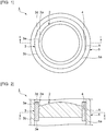
- Fig. 1 is a plan view showing an outer cylinder lens according to a first embodiment of the present invention.
- Fig. 2 is a cross-sectional view taken along the line I-I in Fig. 1 .
- the outer cylinder lens 1 according to this embodiment can be used in a laser ignition device and so on.
- the outer cylinder lens 1 includes a lens 2 and a holder 3 holding the lens 2 thereinside. More specifically, the lens 2 has a lateral surface 2a.
- the holder 3 has an approximately cylindrical shape and has an inner wall surface 3a. The inner wall surface 3a of the holder 3 engages the lateral surface 2a of the lens 2. Thus, the holder 3 holds the lens 2.
- the lens 2 is a convex lens, but the lens 2 may be a concave lens.
- the holder 3 has an outer wall surface 3b which is a surface opposite to a surface on the side of the lens 2.
- the outer wall surface 3b is provided with a single cutaway 4.
- the cutaway 4 may comprise a plurality of cutaways.
- the holder 3 has a first end surface 3d and a second end surface 3e both connected to the outer wall surface 3b.
- the cutaway 4 reaches the first end surface 3d and the second end surface 3e.
- the cutaway 4 may reach one of the first end surface 3d and the second end surface 3e or may reach neither the first end surface 3d nor the second end surface 3e.
- the outer cylinder lens 1 includes an outer cylinder 5 provided around the outer wall surface 3b of the holder 3.
- the outer cylinder 5 has an inner wall surface 5a which is a surface facing the holder 3.
- an empty space A is formed between the outer wall surface 3b of the holder 3 and the inner wall surface 5a of the outer cylinder 3.
- the lens 2 is made of glass.
- the composition of the glass for use in the lens 2 include SiO 2 -B 2 O 3 -RO-based glasses (where R represents Mg, Ca, Sr or Ba), SiO 2 -B 2 O r R' 2 O-based glasses (where R' represents Li, Na or K), SiO 2 -B 2 O 3 RO-R' 2 O-based glasses (where R' represents Li, Na or K), SnO-P 2 O 5 -based glasses, TeO 2 -based glasses, and Bi 2 O 3 -based glasses.
- the composition of the glass for use in the lens 2 is not limited to the above compositions.
- the holder 3 is made of, for example, a SUS material.
- SUS material for use in the holder 3 include SUS430, SUS430F, SF-20F, and SF-20T.
- the holder 3 may be made of a metallic material other than the SUS material.
- the outer cylinder 5 is made of, for example, an appropriate metallic material. In this embodiment, the coefficient of thermal expansion of the outer cylinder 5 is smaller than the coefficient of thermal expansion of the holder 3.
- a feature of this embodiment is that the cutaway 4 is provided in the outer wall surface 3b which is a surface of the holder 3 facing the outer cylinder 5.
- the force applied to the outer cylinder 5 in association with temperature rise can be eased, so that the outer cylinder lens 1 is less likely to be damaged. This will be described below by comparison between this embodiment and a comparative example.
- Fig. 6 is a plan view showing an outer cylinder lens as a comparative example.
- an outer wall surface 3b of a holder 103 is provided with no cutaway.
- the outer cylinder lens 101 is used in a laser ignition device, the temperature of the outer cylinder lens 101 rises when ignition is effected. Then, each member of the outer cylinder lens 101 thermally expands.
- the coefficient of thermal expansion of the holder 103 is larger than the coefficient of thermal expansion of the outer cylinder 5. Therefore, the outer wall surface 3b of the holder 103 presses against the inner wall surface 5a of the outer cylinder 5.
- the outer cylinder 5 may crack.
- the outer wall surface 3b of the holder 3 is provided with a cutaway 4 and an empty space A is thus formed between the outer wall surface 3b of the holder 3 and the inner wall surface 5a of the outer cylinder 5. Therefore, during temperature rise, the holder 3 not only expands toward the outer cylinder 5, but also expands circumferentially toward the empty space A. Thus, the force applied from the holder 3 to the outer cylinder 5 in association with temperature rise can be eased. Hence, the outer cylinder lens 1 is less likely to be damaged.
- the cutaway 4 preferably reaches the first end surface 3d and the second end surface 3e.
- the cutaway 4 can be located across the holder 3 in a direction connecting between the first end surface 3d and the second end surface 3e. Hence, the force applied to the outer cylinder 5 can be effectively eased.
- the cutaway 4 is provided to cut away the outer wall surface 3b in a direction parallel with a tangent line to the outer wall surface 3b of the holder 3 which would be if the cutaway 4 were not provided.
- the shape of the cutaway 4 is not limited to the above shape.
- the cutaway 4 may be in a V-shape, a U-shape or other shapes as viewed from the first end surface 3d.
- the cutaway 4 may be provided helically along the outer wall surface 3b.
- the area of a portion of the outer wall surface 3b of the holder 3 where the cutaway 4 is provided is preferably 1% or more of the whole area of the outer wall surface 3b, more preferably 3% or more thereof, still more preferably 5% or more thereof, and most preferably 7% or more thereof.
- the force applied to the outer cylinder 5 can be further eased. If the proportion of the area of the portion where the cutaway 4 is provided to the whole area of the outer wall surface 3b is too small, the effect of easing the force applied to the outer cylinder 5 in association with temperature rise may not sufficiently be achieved.
- the area of the portion where the cutaway 4 is provided is preferably 50% or less of the whole area of the outer wall surface 3b, more preferably 47% or less thereof, still more preferably 44% or less thereof, and yet still more preferably 41% or less thereof.
- the holder 3 is less likely to be damaged. If the proportion of the area of the portion where the cutaway 4 is provided to the whole area of the outer wall surface 3b is too large, the holder 3 is likely to be deficient in strength and may be damaged.
- the lengths of the parts of the outer cylinder lens 1 along the direction connecting between the first end surface 3d and the second end surface 3e as shown in Fig. 2 are the heights of the parts.
- the length, along the circumferential direction of the outer wall surface 3b, of the portion of the outer wall surface 3b where the cutaway 4 is provided is the width of the portion.
- the area of the portion of the outer wall surface 3b where the cutaway 4 is provided is represented by S1
- the height of the cutaway 4 is represented by Z1
- the width of the cutaway 4 is represented by W
- the whole area of the outer wall surface 3b is represented by S2
- the height of the holder is represented by Z2
- the outside diameter of the holder 3 is represented by L.
- the ratio S1/S2 of the area S1 of the portion of the outer wall surface 3b where the cutaway 4 is provided to the whole area S2 of the outer wall surface 3b can be determined, for example, in the following manner.
- S 1 / S 2 W ⁇ Z 1 / L ⁇ ⁇ ⁇ Z 2
- Sh/S is 0.995 or less where S represents the cross-sectional area between the lens 2 and the outer cylinder 5 and Sh represents the cross-sectional area of the holder 3.
- the cross-sectional area S between the lens 2 and the outer cylinder 5 refers to, for example, a region surrounded by the lateral surface 2a of the lens 2 and the inner wall surface 5a of the outer cylinder 5 in a cross section of the outer cylinder lens 1 as viewed from the direction shown by Fig. 1 (i.e., a cross section as taken along the line II-II in Fig. 2 and further viewed from above).
- the cross-sectional area S is a cross-sectional area including the cutaway 4, a below-described through hole 28 as shown in Fig. 4 or like portion.
- the cross-sectional area Sh of the holder refers to, for example, an area in which the cutaway 4, the below-described through hole 28 as shown in Fig. 4 or like portion is excluded from the portion surrounded by the lateral surface 2a of the lens 2 and the inner wall surface 5a of the outer cylinder 5 in a cross section of the outer cylinder lens 1 as viewed from the direction shown by Fig. 1 (i.e., a cross section as taken along the line II-II in Fig. 2 and further viewed from above).
- Sh/S When Sh/S is 0.995 or less, like the above-described case, the force applied to the outer cylinder 5 in association with temperature rise can be eased, so that the outer cylinder lens 1 is less likely to be damaged.
- a preferred range of Sh/S is 0.99 or less and a more preferred range thereof is 0.985 or less. If Sh/S is too large, the effect of easing the force applied to the outer cylinder 5 in association with temperature rise is not sufficiently achieved.
- Sh/S is preferably 0.8 or more, more preferably 0.85 or more, and still more preferably 0.9 or more. Thus, the holder 3 is less likely to be damaged. If Sh/S is too small, the holder 3 is likely to be deficient in strength and may be damaged.
- Fig. 3 is a plan view showing an outer cylinder lens according to a second embodiment of the present invention.
- the outer cylinder lens 11 is different from the first embodiment in that the holder 3 includes a plurality of cutaways 4.
- the outer cylinder lens 11 has the same structure as the outer cylinder lens 1 according to the first embodiment.
- the outer wall surface 3b of the holder 3 is provided with four cutaways 4.
- the four cutaways 4 are arranged at equally spaced intervals in the circumferential direction of the holder 3.
- the holder 3 includes the plurality of cutaways 4.
- the plurality of cutaways 4 are arranged at equally spaced intervals in the circumferential direction of the holder 3 as described above.
- Fig. 4 is a plan view showing an outer cylinder lens according to a third embodiment of the present invention.
- the outer cylinder lens 21 is different from the first embodiment in that the holder 3 is provided with a through hole 28 passing through from the first end surface 3d to the second end surface 3e.
- the outer cylinder lens 21 has the same structure as the outer cylinder lens 1 according to the first embodiment.
- the outer cylinder lens 21 includes, in addition to the cutaway 4, the through hole 28, the force applied to the outer cylinder 5 in association with temperature rise can be effectively eased. Therefore, the outer cylinder lens 21 is less likely to be damaged.
- Fig. 5 is a schematic cross-sectional view showing a laser ignition device according to a fourth embodiment of the present invention.
- the laser ignition device 30 includes a laser light source 36 and the outer cylinder lens 1.
- a window member 37 is disposed in the outer cylinder 5 of the outer cylinder lens 1 to face the lens 2.
- the window member 37 engages a portion of the inner wall surface 5a located near one end of the outer cylinder 5.
- the location of the window member 37 is not limited to the above location. It is sufficient that the window member 37 be disposed in the side of the outer cylinder lens 1 toward which laser light to be described hereinafter is emitted from the lens 2.
- the window member 37 is made of a material having high thermal resistance and high transparency, for example, sapphire or quartz glass.
- the laser light source 36 is disposed to the side of the lens 2 opposite to the window member 37. Laser light is emitted from the laser light source 36 in the direction shown by the arrow B. The laser light passes through the lens 2, subsequently passes through the window member 37, and then exits from the laser ignition device 30. The laser light is focused by the lens 2, so that ignition is effected.
- the laser ignition device 30 include a window member 37 having thermal resistance equal to or higher than that of the lens 2.
- the outer cylinder lens 1 can be protected from heat when ignition is effected.
- the laser ignition device 30 includes the outer cylinder lens 1 according to the first embodiment.
- the force applied to the outer cylinder 5 in association with temperature rise due to ignition made by the laser ignition device 30 can be eased, so that the outer cylinder lens 1 is less likely to be damaged.
Landscapes
- Physics & Mathematics (AREA)
- Engineering & Computer Science (AREA)
- Optics & Photonics (AREA)
- General Physics & Mathematics (AREA)
- Chemical & Material Sciences (AREA)
- Combustion & Propulsion (AREA)
- Mechanical Engineering (AREA)
- General Engineering & Computer Science (AREA)
- Lenses (AREA)
- Lens Barrels (AREA)
- Semiconductor Lasers (AREA)
Abstract
Provided is an outer cylinder lens that can ease the force applied to an outer cylinder in association with temperature rise and is thus less likely to be damaged. An outer cylinder lens includes a lens 2 and a holder 3 holding the lens 2 thereinside, wherein the holder 3 has an outer wall surface 3b which is a surface opposite to a surface on the side of the lens 2, the outer wall surface 3b is provided with at least one cutaway 4, and the outer cylinder lens further includes an outer cylinder 5 provided around the outer wall surface 3b.
Description
- The present invention relates to outer cylinder lenses with a lens disposed inside an outer cylinder and laser ignition devices including the outer cylinder lenses.
- An outer cylinder lens is used in a laser ignition device for an internal combustion engine of a motor vehicle or the like.
Patent Literature 1 below describes an example of such a laser ignition device including an outer cylinder lens. In the outer cylinder lens described inPatent Literature 1, a holder is provided around an outer periphery of a lens and an outer cylinder is provided around an outer periphery of the holder. High-energy density laser light is focused into a mixed gas in an internal combustion engine by the outer cylinder lens, so that a flame kernel can be generated. - [PTL 1]
JP-A-2013-096392 - The holder of the outer cylinder lens described in
Patent Literature 1 is thermally expanded by temperature rise associated with running of the internal combustion engine. In this situation, due to the thermal expansion of the holder, a large force is applied from the holder to the outer cylinder, so that the outer cylinder may crack. - An object of the present invention is to provide an outer cylinder lens that can ease the force applied to an outer cylinder in association with temperature rise and is thus less likely to be damaged.
- Another object of the present invention is to provide a laser ignition device that can ease the force applied to an outer cylinder in association with temperature rise and thus makes an outer cylinder lens less likely to be damaged.
- An outer cylinder lens according to the present invention includes a lens and a holder holding the lens thereinside, wherein the holder has an outer wall surface which is a surface opposite to a surface on the side of the lens, the outer wall surface is provided with at least one cutaway, and the outer cylinder lens further includes an outer cylinder provided around the outer wall surface.
- In the present invention, preferably, the holder has a first end surface and a second end surface both connected to the outer wall surface and the at least one cutaway reaches the first end surface and the second end surface.
- In the present invention, the holder may have a first end surface and a second end surface both connected to the outer wall surface and the holder may be provided with a through hole passing through from the first end surface to the second end surface.
- In the present invention, an area of a portion of the outer wall surface of the holder where the cutaway is provided is preferably 1% to 50%, both inclusive, of a whole area of the outer wall surface.
- Furthermore, an outer cylinder lens according to the present invention includes: a lens; a holder holding the lens thereinside, the holder having an outer wall surface which is a surface opposite to a surface on the side of the lens; and an outer cylinder provided around the outer wall surface, wherein Sh/S is 0.995 or less where S represents a cross-sectional area between the lens and the outer cylinder and Sh represents a cross-sectional area of the holder.
- Moreover, a laser ignition device according to the present invention includes a laser light source and the above-described outer cylinder lens.
- The present invention enables provision of an outer cylinder lens that can ease the force applied to an outer cylinder in association with temperature rise and is thus less likely to be damaged.
- The present invention also enables provision of a laser ignition device that can ease the force applied to an outer cylinder in association with temperature rise and thus makes an outer cylinder lens less likely to be damaged.
-
- [
Fig. 1]Fig. 1 is a plan view showing an outer cylinder lens according to a first embodiment of the present invention. - [
Fig. 2]Fig. 2 is a cross-sectional view taken along the line I-I inFig. 1 . - [
Fig. 3]Fig. 3 is a plan view showing an outer cylinder lens according to a second embodiment of the present invention. - [
Fig. 4]Fig. 4 is a plan view showing an outer cylinder lens according to a third embodiment of the present invention. - [
Fig. 5]Fig. 5 is a schematic cross-sectional view showing a laser ignition device according to a fourth embodiment of the present invention. - [
Fig. 6]Fig. 6 is a plan view showing an outer cylinder lens as a comparative example. - Hereinafter, a description will be given of preferred embodiments. However, the following embodiments are merely illustrative and the present invention is not limited to the following embodiments. Throughout the drawings, members having substantially the same functions may be referred to by the same reference characters.
-
Fig. 1 is a plan view showing an outer cylinder lens according to a first embodiment of the present invention.Fig. 2 is a cross-sectional view taken along the line I-I inFig. 1 . As shown inFigs. 1 and 2 , theouter cylinder lens 1 according to this embodiment can be used in a laser ignition device and so on. As shown inFig. 1 , theouter cylinder lens 1 includes alens 2 and aholder 3 holding thelens 2 thereinside. More specifically, thelens 2 has alateral surface 2a. Theholder 3 has an approximately cylindrical shape and has aninner wall surface 3a. Theinner wall surface 3a of theholder 3 engages thelateral surface 2a of thelens 2. Thus, theholder 3 holds thelens 2. - In this embodiment, the
lens 2 is a convex lens, but thelens 2 may be a concave lens. - The
holder 3 has anouter wall surface 3b which is a surface opposite to a surface on the side of thelens 2. In this embodiment, theouter wall surface 3b is provided with asingle cutaway 4. Thecutaway 4 may comprise a plurality of cutaways. - As shown in
Fig. 2 , theholder 3 has afirst end surface 3d and asecond end surface 3e both connected to theouter wall surface 3b. Thecutaway 4 reaches thefirst end surface 3d and thesecond end surface 3e. Thecutaway 4 may reach one of thefirst end surface 3d and thesecond end surface 3e or may reach neither thefirst end surface 3d nor thesecond end surface 3e. - The
outer cylinder lens 1 includes anouter cylinder 5 provided around theouter wall surface 3b of theholder 3. Theouter cylinder 5 has aninner wall surface 5a which is a surface facing theholder 3. In a portion of theholder 3 where thecutaway 4 is provided, an empty space A is formed between theouter wall surface 3b of theholder 3 and theinner wall surface 5a of theouter cylinder 3. - The
lens 2 is made of glass. Examples of the composition of the glass for use in thelens 2 include SiO2-B2O3-RO-based glasses (where R represents Mg, Ca, Sr or Ba), SiO2-B2OrR'2O-based glasses (where R' represents Li, Na or K), SiO2-B2O3RO-R'2O-based glasses (where R' represents Li, Na or K), SnO-P2O5-based glasses, TeO2-based glasses, and Bi2O3-based glasses. However, the composition of the glass for use in thelens 2 is not limited to the above compositions. - The
holder 3 is made of, for example, a SUS material. Examples of the SUS material for use in theholder 3 include SUS430, SUS430F, SF-20F, and SF-20T. However, theholder 3 may be made of a metallic material other than the SUS material. Theouter cylinder 5 is made of, for example, an appropriate metallic material. In this embodiment, the coefficient of thermal expansion of theouter cylinder 5 is smaller than the coefficient of thermal expansion of theholder 3. - A feature of this embodiment is that the
cutaway 4 is provided in theouter wall surface 3b which is a surface of theholder 3 facing theouter cylinder 5. Thus, the force applied to theouter cylinder 5 in association with temperature rise can be eased, so that theouter cylinder lens 1 is less likely to be damaged. This will be described below by comparison between this embodiment and a comparative example. -
Fig. 6 is a plan view showing an outer cylinder lens as a comparative example. In theouter cylinder lens 101 as a comparative example, anouter wall surface 3b of aholder 103 is provided with no cutaway. For example, if theouter cylinder lens 101 is used in a laser ignition device, the temperature of theouter cylinder lens 101 rises when ignition is effected. Then, each member of theouter cylinder lens 101 thermally expands. The coefficient of thermal expansion of theholder 103 is larger than the coefficient of thermal expansion of theouter cylinder 5. Therefore, theouter wall surface 3b of theholder 103 presses against theinner wall surface 5a of theouter cylinder 5. When a force is applied from theholder 103 to theouter cylinder 5 in association with temperature rise as just described, theouter cylinder 5 may crack. - Unlike the above, in this embodiment shown in
Fig. 1 , theouter wall surface 3b of theholder 3 is provided with acutaway 4 and an empty space A is thus formed between theouter wall surface 3b of theholder 3 and theinner wall surface 5a of theouter cylinder 5. Therefore, during temperature rise, theholder 3 not only expands toward theouter cylinder 5, but also expands circumferentially toward the empty space A. Thus, the force applied from theholder 3 to theouter cylinder 5 in association with temperature rise can be eased. Hence, theouter cylinder lens 1 is less likely to be damaged. - As in this embodiment, the
cutaway 4 preferably reaches thefirst end surface 3d and thesecond end surface 3e. Thus, thecutaway 4 can be located across theholder 3 in a direction connecting between thefirst end surface 3d and thesecond end surface 3e. Hence, the force applied to theouter cylinder 5 can be effectively eased. - In this embodiment, the
cutaway 4 is provided to cut away theouter wall surface 3b in a direction parallel with a tangent line to theouter wall surface 3b of theholder 3 which would be if thecutaway 4 were not provided. However, the shape of thecutaway 4 is not limited to the above shape. For example, thecutaway 4 may be in a V-shape, a U-shape or other shapes as viewed from thefirst end surface 3d. Alternatively, thecutaway 4 may be provided helically along theouter wall surface 3b. - The area of a portion of the
outer wall surface 3b of theholder 3 where thecutaway 4 is provided is preferably 1% or more of the whole area of theouter wall surface 3b, more preferably 3% or more thereof, still more preferably 5% or more thereof, and most preferably 7% or more thereof. Thus, the force applied to theouter cylinder 5 can be further eased. If the proportion of the area of the portion where thecutaway 4 is provided to the whole area of theouter wall surface 3b is too small, the effect of easing the force applied to theouter cylinder 5 in association with temperature rise may not sufficiently be achieved. Also, the area of the portion where thecutaway 4 is provided is preferably 50% or less of the whole area of theouter wall surface 3b, more preferably 47% or less thereof, still more preferably 44% or less thereof, and yet still more preferably 41% or less thereof. Thus, theholder 3 is less likely to be damaged. If the proportion of the area of the portion where thecutaway 4 is provided to the whole area of theouter wall surface 3b is too large, theholder 3 is likely to be deficient in strength and may be damaged. - Now suppose that the lengths of the parts of the
outer cylinder lens 1 along the direction connecting between thefirst end surface 3d and thesecond end surface 3e as shown inFig. 2 are the heights of the parts. Also suppose that the length, along the circumferential direction of theouter wall surface 3b, of the portion of theouter wall surface 3b where thecutaway 4 is provided is the width of the portion. Also suppose that the area of the portion of theouter wall surface 3b where thecutaway 4 is provided is represented by S1, the height of thecutaway 4 is represented by Z1, the width of thecutaway 4 is represented by W, the whole area of theouter wall surface 3b is represented by S2, the height of the holder is represented by Z2, and the outside diameter of theholder 3 is represented by L. In this case, the ratio S1/S2 of the area S1 of the portion of theouter wall surface 3b where thecutaway 4 is provided to the whole area S2 of theouter wall surface 3b can be determined, for example, in the following manner.
- Another feature of this embodiment is that Sh/S is 0.995 or less where S represents the cross-sectional area between the
lens 2 and theouter cylinder 5 and Sh represents the cross-sectional area of theholder 3. The cross-sectional area S between thelens 2 and theouter cylinder 5 refers to, for example, a region surrounded by thelateral surface 2a of thelens 2 and theinner wall surface 5a of theouter cylinder 5 in a cross section of theouter cylinder lens 1 as viewed from the direction shown byFig. 1 (i.e., a cross section as taken along the line II-II inFig. 2 and further viewed from above). Therefore, the cross-sectional area S is a cross-sectional area including thecutaway 4, a below-described throughhole 28 as shown inFig. 4 or like portion. The cross-sectional area Sh of the holder refers to, for example, an area in which thecutaway 4, the below-described throughhole 28 as shown inFig. 4 or like portion is excluded from the portion surrounded by thelateral surface 2a of thelens 2 and theinner wall surface 5a of theouter cylinder 5 in a cross section of theouter cylinder lens 1 as viewed from the direction shown byFig. 1 (i.e., a cross section as taken along the line II-II inFig. 2 and further viewed from above). - When Sh/S is 0.995 or less, like the above-described case, the force applied to the
outer cylinder 5 in association with temperature rise can be eased, so that theouter cylinder lens 1 is less likely to be damaged. A preferred range of Sh/S is 0.99 or less and a more preferred range thereof is 0.985 or less. If Sh/S is too large, the effect of easing the force applied to theouter cylinder 5 in association with temperature rise is not sufficiently achieved. Furthermore, Sh/S is preferably 0.8 or more, more preferably 0.85 or more, and still more preferably 0.9 or more. Thus, theholder 3 is less likely to be damaged. If Sh/S is too small, theholder 3 is likely to be deficient in strength and may be damaged. -
Fig. 3 is a plan view showing an outer cylinder lens according to a second embodiment of the present invention. Theouter cylinder lens 11 is different from the first embodiment in that theholder 3 includes a plurality ofcutaways 4. For the rest, theouter cylinder lens 11 has the same structure as theouter cylinder lens 1 according to the first embodiment. - More specifically, in this embodiment, the
outer wall surface 3b of theholder 3 is provided with fourcutaways 4. The fourcutaways 4 are arranged at equally spaced intervals in the circumferential direction of theholder 3. - The effect of easing the force applied from the
holder 3 to theouter cylinder 5 is particularly significant at and near eachcutaway 4. In this embodiment, theholder 3 includes the plurality ofcutaways 4. In addition, the plurality ofcutaways 4 are arranged at equally spaced intervals in the circumferential direction of theholder 3 as described above. Thus, the force applied to theouter cylinder 5 in association with temperature rise can be further eased, so that theouter cylinder lens 1 is even less likely to be damaged. -
Fig. 4 is a plan view showing an outer cylinder lens according to a third embodiment of the present invention. Theouter cylinder lens 21 is different from the first embodiment in that theholder 3 is provided with a throughhole 28 passing through from thefirst end surface 3d to thesecond end surface 3e. For the rest, theouter cylinder lens 21 has the same structure as theouter cylinder lens 1 according to the first embodiment. - Since the
outer cylinder lens 21 includes, in addition to thecutaway 4, the throughhole 28, the force applied to theouter cylinder 5 in association with temperature rise can be effectively eased. Therefore, theouter cylinder lens 21 is less likely to be damaged. -
Fig. 5 is a schematic cross-sectional view showing a laser ignition device according to a fourth embodiment of the present invention. Thelaser ignition device 30 includes alaser light source 36 and theouter cylinder lens 1. - A
window member 37 is disposed in theouter cylinder 5 of theouter cylinder lens 1 to face thelens 2. Thewindow member 37 engages a portion of theinner wall surface 5a located near one end of theouter cylinder 5. However, the location of thewindow member 37 is not limited to the above location. It is sufficient that thewindow member 37 be disposed in the side of theouter cylinder lens 1 toward which laser light to be described hereinafter is emitted from thelens 2. Thewindow member 37 is made of a material having high thermal resistance and high transparency, for example, sapphire or quartz glass. - The
laser light source 36 is disposed to the side of thelens 2 opposite to thewindow member 37. Laser light is emitted from thelaser light source 36 in the direction shown by the arrow B. The laser light passes through thelens 2, subsequently passes through thewindow member 37, and then exits from thelaser ignition device 30. The laser light is focused by thelens 2, so that ignition is effected. - As in this embodiment, it is preferred that the
laser ignition device 30 include awindow member 37 having thermal resistance equal to or higher than that of thelens 2. Thus, theouter cylinder lens 1 can be protected from heat when ignition is effected. - The
laser ignition device 30 according to this embodiment includes theouter cylinder lens 1 according to the first embodiment. Thus, the force applied to theouter cylinder 5 in association with temperature rise due to ignition made by thelaser ignition device 30 can be eased, so that theouter cylinder lens 1 is less likely to be damaged. -
- 1
- outer cylinder lens
- 2
- lens
- 2a
- lateral surface
- 3
- holder
- 3a
- inner wall surface
- 3b
- outer wall surface
- 3d, 3e
- first end surface, second end surface
- 4
- cutaway
- 5
- outer cylinder
- 11. 21
- outer cylinder lens
- 28
- through hole
- 30
- laser ignition device
- 36
- laser light source
- 37
- window member
- 101
- outer cylinder lens
- 103
- holder
Claims (6)
- An outer cylinder lens comprising:a lens; anda holder holding the lens thereinside,wherein the holder has an outer wall surface which is a surface opposite to a surface on the side of the lens,the outer wall surface is provided with at least one cutaway, andthe outer cylinder lens further comprises an outer cylinder provided around the outer wall surface.
- The outer cylinder lens according to claim 1, wherein
the holder has a first end surface and a second end surface both connected to the outer wall surface, and
the at least one cutaway reaches the first end surface and the second end surface. - The outer cylinder lens according to claim 1 or 2, wherein
the holder has a first end surface and a second end surface both connected to the outer wall surface, and
the holder is provided with a through hole passing through from the first end surface to the second end surface. - The outer cylinder lens according to any one of claims 1 to 3, wherein an area of a portion of the outer wall surface of the holder where the cutaway is provided is 1% to 50%, both inclusive, of a whole area of the outer wall surface.
- An outer cylinder lens comprising:a lens;a holder holding the lens thereinside, the holder having an outer wall surface which is a surface opposite to a surface on the side of the lens; andan outer cylinder provided around the outer wall surface,wherein Sh/S is 0.995 or less where S represents a cross-sectional area between the lens and the outer cylinder and Sh represents a cross-sectional area of the holder.
- A laser ignition device comprising:a laser light source; andthe outer cylinder lens according to any one of claims 1 to 5.
Applications Claiming Priority (2)
| Application Number | Priority Date | Filing Date | Title |
|---|---|---|---|
| JP2017017350A JP2018124469A (en) | 2017-02-02 | 2017-02-02 | Outer cylinder lens and laser ignition device |
| PCT/JP2017/042201 WO2018142730A1 (en) | 2017-02-02 | 2017-11-24 | Outer cylinder lens and laser ignition device |
Publications (1)
| Publication Number | Publication Date |
|---|---|
| EP3579038A1 true EP3579038A1 (en) | 2019-12-11 |
Family
ID=63040460
Family Applications (1)
| Application Number | Title | Priority Date | Filing Date |
|---|---|---|---|
| EP17895462.4A Withdrawn EP3579038A1 (en) | 2017-02-02 | 2017-11-24 | Outer cylinder lens and laser ignition device |
Country Status (3)
| Country | Link |
|---|---|
| EP (1) | EP3579038A1 (en) |
| JP (1) | JP2018124469A (en) |
| WO (1) | WO2018142730A1 (en) |
Family Cites Families (5)
| Publication number | Priority date | Publication date | Assignee | Title |
|---|---|---|---|---|
| JPS59178607U (en) * | 1983-05-16 | 1984-11-29 | オリンパス光学工業株式会社 | Lens barrel light shielding device |
| JP2007239603A (en) * | 2006-03-08 | 2007-09-20 | Nissan Motor Co Ltd | Variable compression ratio engine |
| JP5873689B2 (en) | 2011-11-07 | 2016-03-01 | 株式会社日本自動車部品総合研究所 | Laser ignition device |
| JP6300584B2 (en) * | 2014-03-10 | 2018-03-28 | オリンパス株式会社 | Lens holding frame, lens unit, and interferometer |
| JP6485745B2 (en) * | 2015-06-10 | 2019-03-20 | 株式会社リコー | Laser device, ignition device, and adjustment method of laser device |
-
2017
- 2017-02-02 JP JP2017017350A patent/JP2018124469A/en active Pending
- 2017-11-24 EP EP17895462.4A patent/EP3579038A1/en not_active Withdrawn
- 2017-11-24 WO PCT/JP2017/042201 patent/WO2018142730A1/en not_active Ceased
Also Published As
| Publication number | Publication date |
|---|---|
| JP2018124469A (en) | 2018-08-09 |
| WO2018142730A1 (en) | 2018-08-09 |
Similar Documents
| Publication | Publication Date | Title |
|---|---|---|
| US5536998A (en) | Fluorescent lamp with a protective assembly | |
| US7231817B2 (en) | Inspection system for a turbine blade region of a turbine engine | |
| US5101135A (en) | Spark plug for use in an internal combustion engine | |
| MX166601B (en) | INTEGRAL RETAINER, THERMAL SCREEN AND SET | |
| JP6263411B2 (en) | Optical sensor chip | |
| ES2081180T3 (en) | PLUG WITH GAS OUTLET. | |
| CN109642530B (en) | end cap | |
| US4065372A (en) | Electrochemical oxygen sensing element, particularly for determination of oxygen content in the exhaust gases of automotive internal combustion engines | |
| BR0202162A (en) | Methods for replacing combustor liner panels | |
| EP3081854A1 (en) | Light guide with reduced light attenuation | |
| UY24185A1 (en) | OPTICAL WAVE GUIDE | |
| ES2120569T3 (en) | HIGH TEMPERATURE ALLOYS. | |
| US4181397A (en) | Fibre-optic cable | |
| US6152087A (en) | Boiler tube protector and a method for attaching such protector to a boiler tube | |
| EP0369958A2 (en) | Protection device for sensor means | |
| US7872815B2 (en) | Optical sensor | |
| EP1168014A3 (en) | Temperature-compensating arrangements and methods for optical fiber | |
| JP2018124469A (en) | Outer cylinder lens and laser ignition device | |
| US2218622A (en) | Thermocouple | |
| KR850700159A (en) | Fiber optic connector | |
| EP4368880A1 (en) | Lightguide for an automobile lamp | |
| DE60324327D1 (en) | OPTICAL LENS ASSEMBLY | |
| ES2195209T3 (en) | PRESSURE PROOF HOUSING AND PROCEDURE FOR MANUFACTURING. | |
| US1516327A (en) | Piston ring | |
| ES277023U (en) | Light metal pistons. |
Legal Events
| Date | Code | Title | Description |
|---|---|---|---|
| PUAI | Public reference made under article 153(3) epc to a published international application that has entered the european phase |
Free format text: ORIGINAL CODE: 0009012 |
|
| 17P | Request for examination filed |
Effective date: 20190516 |
|
| AK | Designated contracting states |
Kind code of ref document: A1 Designated state(s): AL AT BE BG CH CY CZ DE DK EE ES FI FR GB GR HR HU IE IS IT LI LT LU LV MC MK MT NL NO PL PT RO RS SE SI SK SM TR |
|
| AX | Request for extension of the european patent |
Extension state: BA ME |
|
| DAV | Request for validation of the european patent (deleted) | ||
| DAX | Request for extension of the european patent (deleted) | ||
| STAA | Information on the status of an ep patent application or granted ep patent |
Free format text: STATUS: THE APPLICATION HAS BEEN WITHDRAWN |
|
| 18W | Application withdrawn |
Effective date: 20201116 |