EP3579031A1 - Small form factor multi-fiber connector - Google Patents
Small form factor multi-fiber connector Download PDFInfo
- Publication number
- EP3579031A1 EP3579031A1 EP19178199.6A EP19178199A EP3579031A1 EP 3579031 A1 EP3579031 A1 EP 3579031A1 EP 19178199 A EP19178199 A EP 19178199A EP 3579031 A1 EP3579031 A1 EP 3579031A1
- Authority
- EP
- European Patent Office
- Prior art keywords
- ferrule
- fssa
- endface
- adapter
- ngdc
- Prior art date
- Legal status (The legal status is an assumption and is not a legal conclusion. Google has not performed a legal analysis and makes no representation as to the accuracy of the status listed.)
- Granted
Links
Images











Classifications
-
- G—PHYSICS
- G02—OPTICS
- G02B—OPTICAL ELEMENTS, SYSTEMS OR APPARATUS
- G02B6/00—Light guides; Structural details of arrangements comprising light guides and other optical elements, e.g. couplings
- G02B6/24—Coupling light guides
- G02B6/36—Mechanical coupling means
- G02B6/38—Mechanical coupling means having fibre to fibre mating means
- G02B6/3807—Dismountable connectors, i.e. comprising plugs
- G02B6/3873—Connectors using guide surfaces for aligning ferrule ends, e.g. tubes, sleeves, V-grooves, rods, pins, balls
- G02B6/3882—Connectors using guide surfaces for aligning ferrule ends, e.g. tubes, sleeves, V-grooves, rods, pins, balls using rods, pins or balls to align a pair of ferrule ends
-
- G—PHYSICS
- G02—OPTICS
- G02B—OPTICAL ELEMENTS, SYSTEMS OR APPARATUS
- G02B6/00—Light guides; Structural details of arrangements comprising light guides and other optical elements, e.g. couplings
- G02B6/24—Coupling light guides
- G02B6/36—Mechanical coupling means
- G02B6/38—Mechanical coupling means having fibre to fibre mating means
- G02B6/3807—Dismountable connectors, i.e. comprising plugs
- G02B6/381—Dismountable connectors, i.e. comprising plugs of the ferrule type, e.g. fibre ends embedded in ferrules, connecting a pair of fibres
- G02B6/3825—Dismountable connectors, i.e. comprising plugs of the ferrule type, e.g. fibre ends embedded in ferrules, connecting a pair of fibres with an intermediate part, e.g. adapter, receptacle, linking two plugs
-
- G—PHYSICS
- G02—OPTICS
- G02B—OPTICAL ELEMENTS, SYSTEMS OR APPARATUS
- G02B6/00—Light guides; Structural details of arrangements comprising light guides and other optical elements, e.g. couplings
- G02B6/24—Coupling light guides
- G02B6/36—Mechanical coupling means
- G02B6/38—Mechanical coupling means having fibre to fibre mating means
- G02B6/3807—Dismountable connectors, i.e. comprising plugs
- G02B6/381—Dismountable connectors, i.e. comprising plugs of the ferrule type, e.g. fibre ends embedded in ferrules, connecting a pair of fibres
- G02B6/3826—Dismountable connectors, i.e. comprising plugs of the ferrule type, e.g. fibre ends embedded in ferrules, connecting a pair of fibres characterised by form or shape
- G02B6/3831—Dismountable connectors, i.e. comprising plugs of the ferrule type, e.g. fibre ends embedded in ferrules, connecting a pair of fibres characterised by form or shape comprising a keying element on the plug or adapter, e.g. to forbid wrong connection
-
- G—PHYSICS
- G02—OPTICS
- G02B—OPTICAL ELEMENTS, SYSTEMS OR APPARATUS
- G02B6/00—Light guides; Structural details of arrangements comprising light guides and other optical elements, e.g. couplings
- G02B6/24—Coupling light guides
- G02B6/36—Mechanical coupling means
- G02B6/38—Mechanical coupling means having fibre to fibre mating means
- G02B6/3807—Dismountable connectors, i.e. comprising plugs
- G02B6/3873—Connectors using guide surfaces for aligning ferrule ends, e.g. tubes, sleeves, V-grooves, rods, pins, balls
- G02B6/3874—Connectors using guide surfaces for aligning ferrule ends, e.g. tubes, sleeves, V-grooves, rods, pins, balls using tubes, sleeves to align ferrules
- G02B6/3877—Split sleeves
-
- G—PHYSICS
- G02—OPTICS
- G02B—OPTICAL ELEMENTS, SYSTEMS OR APPARATUS
- G02B6/00—Light guides; Structural details of arrangements comprising light guides and other optical elements, e.g. couplings
- G02B6/24—Coupling light guides
- G02B6/36—Mechanical coupling means
- G02B6/38—Mechanical coupling means having fibre to fibre mating means
- G02B6/3807—Dismountable connectors, i.e. comprising plugs
- G02B6/3873—Connectors using guide surfaces for aligning ferrule ends, e.g. tubes, sleeves, V-grooves, rods, pins, balls
- G02B6/3885—Multicore or multichannel optical connectors, i.e. one single ferrule containing more than one fibre, e.g. ribbon type
Definitions
- the present disclosure is related to fiber optic connectors and more specifically to small form factor multi-fiber connectors.
- the Next Generation Data Center Connector is a 12 fiber MPO connector with a small form factor.
- the design allows for a connector with 12 fibers to fit into an adapter which fits into approximately the same size opening as a simplex LC adapter.
- 144 NGDC adapters 1 can fit into a 1RU patch panel 2, providing 1728 fibers per RU.
- Figs. 2-5 show the NGDC adapter and connector.
- Pins 3 held in each Male NGDC adapter 4 align the connectors inside the Male NGDC adapter when interacting with holes 5 located in the Female NGDC ferrule 6 .
- the female features are located on the NGDC ferrule and the male features are located inside the NGDC adapter.
- the pins are held in the Male adapter using a metal bracket 7 and supported by circular molded features 8 .
- the metal bracket does not offer much support to the pins, leaving the pins and bracket susceptible to bending during connector insertion and pin cleaning with swabs, possibly causing misalignment and or damage to the connector's ferrule alignment holes.
- the new design described in this application offers more support for the connectors, and, eliminates the possibility of pin or support bracket damage and misalignment by using split sleeves or similar devices in the adapter to align male features on the multi-fiber ferrule.
- the female features would be located in the NGDC adapter and the male features would be located on the NGDC ferrule.
- LC and SC connectors utilize similar designs.
- the first part included in the FSSA is the front adapter half 9 shown in Figs. 6 , 7 , and 8 .
- Cylindrical holes 10 will be used to hold 2 separate split sleeves 15 (see Fig. 11 ).
- a plastic lip 11 will be used to keep the split sleeve from falling out of the adapter.
- Windows 12 will be used to attach the rear adapter half of the FSSA to the front half.
- the second part included in the FSSA is the rear adapter half 13 , shown in Figs. 9 and 10 .
- Male latch features 14 allow the rear half and front half of the FSSA to be secured together.
- the rear half of the FSSA includes the cylindrical holes 10 and plastic lips 11 to prohibit movement of the split sleeves when assembled.
- the third part included in the FSSA is the split sleeve 15 shown in Fig. 11 .
- the split sleeve will be similar to the ceramic split sleeve seen in LC and SC adapters, but could be made from another material or incorporated into an adapter half. Two split sleeves can be placed in each adapter.
- the metal clip 16 included in the FSSA is seen both in the Male NGDC adapter and the preferred Female Split Sleeve Adapter.
- the metal clip is placed around the adapter to allow the adapter to be snapped into patch panels using flexible fingers 17 .
- split sleeves 15 must be placed into the front half of the FSSA 9 .
- the plastic lips will stop the split sleeves from falling out of the cylindrical holes.
- the rear half of the FSSA 13 will be attached to the front half of the FSSA, utilizing the latching features located on both halves of the FSSA.
- the plastic lips located on the front and rear halves of the FSSA will prohibit movement of the split sleeves after attachment is complete.
- the metal clip 16 will be placed around the FSSA to complete the assembly of the FSSA.
- Fig. 14 shows an MNF 18 .
- the MNF 18 has a base portion 34 with an endface portion 35 protruding from the base portion.
- Two cylindrical alignment towers 19 also protrude from the base portion 34 parallel and on either side of the endface portion 35 .
- the MNF 18 ( Fig. 14 ) must have male features to interact with the split sleeves (not shown) located in the FSSA.
- the male features are the two cylindrical alignment towers 19 located on each side of the MNF.
- the two towers can be designed as an integral part of the ferrule, or could be separate components which can be inserted into the ferrule within receiving hole or insert molded. In a preferred embodiment, the towers 19 are not proud of the endface of the ferrule.
- the NGDC connector 20 with the MNF ferrule can be used with the FSSA to properly align 12 fibers inside each FSSA when two connectors are mated such that the opposing fiber makes physical contact ( Figs. 17 and 18 ).
- a first alternative embodiment shows molded webs 21 which can be added to provide additional support to the cylindrical alignment towers located on the NGDC ferrule 22 .
- a split sleeve slot 23 fits around the web to properly hold the ferrule.
- Keying features 26 must be added to a possibly molded split sleeve 27 to ensure no rotation of the split sleeve within the adapter (See Figures 20 and 21 ).
- a second alternative embodiment has instead of having two towers in the ferrule, one cylindrical tower 24 can be used to properly center the NGDC ferrule 25 inside of the FSSA.
- the cylindrical towers 24 When mated to another ferrule, the cylindrical towers 24 will be on opposite sides of each other, allowing the ferrules to align properly within the split sleeves 15 .
- a modified polishing machine would be needed to properly polish the ferrule as the cylindrical tower 24 stands proud of the ferrule endface.
Landscapes
- Physics & Mathematics (AREA)
- General Physics & Mathematics (AREA)
- Optics & Photonics (AREA)
- Mechanical Coupling Of Light Guides (AREA)
Abstract
Description
- This application claims priority to
U.S. Provisional Application No. 62/680,642, filed June 5, 2018 - The present disclosure is related to fiber optic connectors and more specifically to small form factor multi-fiber connectors.
- The Next Generation Data Center Connector (NGDC) is a 12 fiber MPO connector with a small form factor. The design allows for a connector with 12 fibers to fit into an adapter which fits into approximately the same size opening as a simplex LC adapter. As shown in
Fig. 1 , with this design, 144 NGDC adapters 1 can fit into a1RU patch panel 2, providing 1728 fibers per RU. -
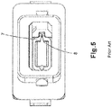
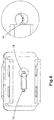
Figs. 2-5 show the NGDC adapter and connector.Pins 3 held in eachMale NGDC adapter 4 align the connectors inside the Male NGDC adapter when interacting withholes 5 located in theFemale NGDC ferrule 6. With this design, the female features are located on the NGDC ferrule and the male features are located inside the NGDC adapter. The pins are held in the Male adapter using ametal bracket 7 and supported by circularmolded features 8. The metal bracket does not offer much support to the pins, leaving the pins and bracket susceptible to bending during connector insertion and pin cleaning with swabs, possibly causing misalignment and or damage to the connector's ferrule alignment holes. -
-
Fig. 1 is an isometric view of a 1 RU patch panel using Next Generation Data Center (NGDC) adapters. -
Fig. 2 is a front view of an NGDC adapter. -
Fig. 3 is an isometric view of the NGDC adapter ofFig. 2 . -
Fig. 4 is an isometric view of an NGDC connector. -
Fig. 5 is a front view of the NGDC adapter ofFig. 2 with one of the pins removed to show the features used to hold the pins in the adapter. -
Fig. 6 is a front isometric view of a front half of a Female Split Sleeve Adapter (FSSA). -
Fig. 7 is a rear isometric view of the front FSSA half ofFig. 6 . -
Fig. 8 is a rear view of the front FSSA half highlighting the cylindrical holes used to hold the split sleeves. -
Fig. 9 is a front isometric view of a rear FSSA half. -
Fig. 10 is a rear isometric view of the rear FSSA half ofFig. 10 . -
Fig. 11 is an isometric view of a split sleeve to be used in the FSSA. -
Fig. 12 is an isometric view of a metal clip to be used with the FSSA. -
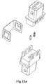
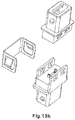
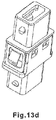
Fig. 13 are isometric views showing the assembly of an FSSA. -
Fig. 14 is a front isometric view of a Male NGDC Ferrule (MNF). -
Fig. 15 is a front isometric view of a connector using the MNF ofFig. 14 -
Fig. 16 shows that the alignment towers of the MNF should not be proud of the ferrule. -
Fig. 17 is an isometric view of two connectors with MNF ferrules installed in a FSSA. -
Fig. 18 shows a cross section view of 2 MNFs installed in a FSSA using split sleeves. -
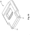
Fig. 19 is an isometric view of a first alternative MNF. -
Fig. 20 is an isometric view of a keyed split sleeve to go with the alternate MNF ofFig. 19 . -
Fig. 21 is a cross-sectional view of an alternative FSSA with keying features for the keyed split sleeve ofFig. 20 . -
Fig. 22 is an isometric view of a second alternative MNF. -
Fig. 23 is a cross-sectional view of two alternate MNFs ofFig. 22 installed in a FSSA. - The new design described in this application offers more support for the connectors, and, eliminates the possibility of pin or support bracket damage and misalignment by using split sleeves or similar devices in the adapter to align male features on the multi-fiber ferrule. For the following design, the female features would be located in the NGDC adapter and the male features would be located on the NGDC ferrule. Currently, LC and SC connectors utilize similar designs.
- The first part included in the FSSA is the
front adapter half 9 shown inFigs. 6 ,7 , and8 .Cylindrical holes 10 will be used to hold 2 separate split sleeves 15 (seeFig. 11 ). Aplastic lip 11 will be used to keep the split sleeve from falling out of the adapter. Windows 12 will be used to attach the rear adapter half of the FSSA to the front half. - The second part included in the FSSA is the
rear adapter half 13, shown inFigs. 9 and10 . Male latch features 14 allow the rear half and front half of the FSSA to be secured together. Similar to the front half, the rear half of the FSSA includes thecylindrical holes 10 andplastic lips 11 to prohibit movement of the split sleeves when assembled. - The third part included in the FSSA is the
split sleeve 15 shown inFig. 11 . The split sleeve will be similar to the ceramic split sleeve seen in LC and SC adapters, but could be made from another material or incorporated into an adapter half. Two split sleeves can be placed in each adapter. - The final part, the
metal clip 16 included in the FSSA is seen both in the Male NGDC adapter and the preferred Female Split Sleeve Adapter. The metal clip is placed around the adapter to allow the adapter to be snapped into patch panels usingflexible fingers 17. - To assemble the FSSA, as shown in
Fig. 13 , splitsleeves 15 must be placed into the front half of the FSSA 9. The plastic lips will stop the split sleeves from falling out of the cylindrical holes. The rear half of the FSSA 13 will be attached to the front half of the FSSA, utilizing the latching features located on both halves of the FSSA. The plastic lips located on the front and rear halves of the FSSA will prohibit movement of the split sleeves after attachment is complete. Themetal clip 16 will be placed around the FSSA to complete the assembly of the FSSA. -
Fig. 14 shows an MNF 18. TheMNF 18 has abase portion 34 with anendface portion 35 protruding from the base portion. Twocylindrical alignment towers 19 also protrude from thebase portion 34 parallel and on either side of theendface portion 35. In order to use the FSSA, the MNF 18 (Fig. 14 ) must have male features to interact with the split sleeves (not shown) located in the FSSA. The male features are the twocylindrical alignment towers 19 located on each side of the MNF. The two towers can be designed as an integral part of the ferrule, or could be separate components which can be inserted into the ferrule within receiving hole or insert molded. In a preferred embodiment, thetowers 19 are not proud of the endface of the ferrule. TheNGDC connector 20 with the MNF ferrule (Fig. 15 ) can be used with the FSSA to properly align 12 fibers inside each FSSA when two connectors are mated such that the opposing fiber makes physical contact (Figs. 17 and18 ). - As shown in
Figs. 19 - 21 , a first alternative embodiment shows moldedwebs 21 which can be added to provide additional support to the cylindrical alignment towers located on theNGDC ferrule 22. Asplit sleeve slot 23 fits around the web to properly hold the ferrule. Keying features 26 must be added to a possibly molded splitsleeve 27 to ensure no rotation of the split sleeve within the adapter (SeeFigures 20 and21 ). - As shown in
Figs. 22 and23 , a second alternative embodiment has instead of having two towers in the ferrule, onecylindrical tower 24 can be used to properly center theNGDC ferrule 25 inside of the FSSA. When mated to another ferrule, thecylindrical towers 24 will be on opposite sides of each other, allowing the ferrules to align properly within thesplit sleeves 15. A modified polishing machine would be needed to properly polish the ferrule as thecylindrical tower 24 stands proud of the ferrule endface. - While particular embodiments and applications of the present disclosure have been illustrated and described, it is to be understood that the disclosure is not limited to the precise construction and compositions disclosed herein and that various modifications, changes, and variations may be apparent from the foregoing without departing from the scope of the disclosure as described.
Claims (4)
- A fiber optic connector comprising:a housing; anda ferrule contained within the housing, the ferrule having a base portion, an endface portion protruding from the base, and at least one alignment tower extending from the base portion parallel to the endface portion.
- The fiber optic connector of claim 1, wherein the ferrule has two alignment towers, one on each side of the endface portion.
- The fiber optic connector of claim 1, wherein the at least one alignment tower extends a length from the base portion which is the same as a length that the endface portion extends form the base portion.
- The fiber optic connector of claim 1 wherein the alignment tower is connected to the endface portion via webbing.
Applications Claiming Priority (2)
| Application Number | Priority Date | Filing Date | Title |
|---|---|---|---|
| US201862680642P | 2018-06-05 | 2018-06-05 | |
| US16/429,601 US10948663B2 (en) | 2018-06-05 | 2019-06-03 | Small form factor multi-fiber connector |
Publications (2)
| Publication Number | Publication Date |
|---|---|
| EP3579031A1 true EP3579031A1 (en) | 2019-12-11 |
| EP3579031B1 EP3579031B1 (en) | 2023-10-04 |
Family
ID=66770227
Family Applications (1)
| Application Number | Title | Priority Date | Filing Date |
|---|---|---|---|
| EP19178199.6A Active EP3579031B1 (en) | 2018-06-05 | 2019-06-04 | Small form factor multi-fiber connector |
Country Status (2)
| Country | Link |
|---|---|
| US (2) | US10948663B2 (en) |
| EP (1) | EP3579031B1 (en) |
Cited By (1)
| Publication number | Priority date | Publication date | Assignee | Title |
|---|---|---|---|---|
| US12298569B2 (en) | 2018-11-14 | 2025-05-13 | Us Conec Ltd. | Guide pin holder for guide pins in an adapter |
Families Citing this family (4)
| Publication number | Priority date | Publication date | Assignee | Title |
|---|---|---|---|---|
| US11294135B2 (en) | 2008-08-29 | 2022-04-05 | Corning Optical Communications LLC | High density and bandwidth fiber optic apparatuses and related equipment and methods |
| WO2010148336A1 (en) * | 2009-06-19 | 2010-12-23 | Corning Cable Systems Llc | High density and bandwidth fiber optic apparatuses and related equipment and methods |
| WO2021217054A1 (en) | 2020-04-23 | 2021-10-28 | US Conec, Ltd | Fiber optic ferrule and fiber optic ferrule receiver |
| US12554087B2 (en) * | 2022-03-23 | 2026-02-17 | Panduit Corp. | High-density fiber management system |
Citations (5)
| Publication number | Priority date | Publication date | Assignee | Title |
|---|---|---|---|---|
| US5838856A (en) * | 1995-10-31 | 1998-11-17 | Daewoo Telecom, Ltd. | Optical-fiber cable connector assembly |
| US6168317B1 (en) * | 1998-04-30 | 2001-01-02 | Lucent Technologies Inc. | Alignment adapter for an optical connector and method for making same |
| US20040042731A1 (en) * | 2002-09-03 | 2004-03-04 | Hall Thomas A. | Multi-fiber optic device |
| WO2006036685A2 (en) * | 2004-09-27 | 2006-04-06 | Adamant Kogyo Co., Ltd. | Neutral gender mt-type ferrule, adapter, and polishing method |
| WO2016053853A1 (en) * | 2014-10-03 | 2016-04-07 | Corning Optical Communications LLC | Ferrule assembly for a fiber optic connector |
Family Cites Families (9)
| Publication number | Priority date | Publication date | Assignee | Title |
|---|---|---|---|---|
| US4896938A (en) | 1983-08-29 | 1990-01-30 | American Telephone And Telegraph Company, At&T Bell Laboratories | Optical fiber connector comprising glass tubes |
| US5239603A (en) | 1991-06-12 | 1993-08-24 | Kyocera Corporation | Integrally-molded ceramic alignment sleeve for optical fiber connector and method of producing the same |
| US5408557A (en) | 1994-04-20 | 1995-04-18 | Hsu; Chung-Tang | FC-type optical fiber cable connector's adaptor |
| US6283644B1 (en) | 1996-01-18 | 2001-09-04 | Stratos Lightwave, Inc. | Optical package with alignment means and method of assembling an optical package |
| US5577644A (en) | 1996-02-12 | 1996-11-26 | Chen; Chao-Yang | Toy doll and hanger assembly |
| JP2987356B2 (en) | 1998-02-24 | 1999-12-06 | 沖電気工業株式会社 | Optical connector |
| JP3078254B2 (en) | 1998-02-24 | 2000-08-21 | 富士通株式会社 | Optical semiconductor module, optical connector, and shape-converting optical connector structure |
| US7186035B2 (en) | 2004-05-12 | 2007-03-06 | Avago Technologies Fiber Ip (Singapore) Pte. Ltd. | Optical fibre connector |
| US9935808B2 (en) | 2015-06-09 | 2018-04-03 | Samsung Electronics Co., Ltd. | Method for determining reserved tones and transmitter for performing PAPR reduction using tone reservation |
-
2019
- 2019-06-03 US US16/429,601 patent/US10948663B2/en active Active
- 2019-06-04 EP EP19178199.6A patent/EP3579031B1/en active Active
-
2021
- 2021-03-15 US US17/201,607 patent/US20210199900A1/en not_active Abandoned
Patent Citations (5)
| Publication number | Priority date | Publication date | Assignee | Title |
|---|---|---|---|---|
| US5838856A (en) * | 1995-10-31 | 1998-11-17 | Daewoo Telecom, Ltd. | Optical-fiber cable connector assembly |
| US6168317B1 (en) * | 1998-04-30 | 2001-01-02 | Lucent Technologies Inc. | Alignment adapter for an optical connector and method for making same |
| US20040042731A1 (en) * | 2002-09-03 | 2004-03-04 | Hall Thomas A. | Multi-fiber optic device |
| WO2006036685A2 (en) * | 2004-09-27 | 2006-04-06 | Adamant Kogyo Co., Ltd. | Neutral gender mt-type ferrule, adapter, and polishing method |
| WO2016053853A1 (en) * | 2014-10-03 | 2016-04-07 | Corning Optical Communications LLC | Ferrule assembly for a fiber optic connector |
Cited By (1)
| Publication number | Priority date | Publication date | Assignee | Title |
|---|---|---|---|---|
| US12298569B2 (en) | 2018-11-14 | 2025-05-13 | Us Conec Ltd. | Guide pin holder for guide pins in an adapter |
Also Published As
| Publication number | Publication date |
|---|---|
| US10948663B2 (en) | 2021-03-16 |
| US20200064562A1 (en) | 2020-02-27 |
| US20210199900A1 (en) | 2021-07-01 |
| EP3579031B1 (en) | 2023-10-04 |
Similar Documents
| Publication | Publication Date | Title |
|---|---|---|
| US10948663B2 (en) | Small form factor multi-fiber connector | |
| US12013578B2 (en) | Multifiber fiber optic connectors, cable assemblies and methods of making the same | |
| CN109752803B (en) | Multi-fiber push-in type optical fiber connector | |
| US10444444B2 (en) | Remote release tab connector assembly | |
| US12276843B2 (en) | Fiber optic connectors and fiber optic connection systems | |
| CN113253395B (en) | Connector with changeable polarity | |
| US9823424B2 (en) | Ferrule assembly for a fiber optic connector | |
| US20150355415A1 (en) | Fiber optic connector with ferrule boot | |
| CN101501544A (en) | Reinforced Fiber Optic Connector Assemblies | |
| CZ227393A3 (en) | Connector for connecting optical fibers | |
| EP1139127A3 (en) | Apparatus and method for assembling and aligning a plurality of optical fibers | |
| EP1148366A3 (en) | Eccentricity adjustable optical fiber connector | |
| CN202453542U (en) | Optical fiber connector | |
| EP1043611A3 (en) | Optical fiber connector | |
| EP3021145A1 (en) | Optical adaptor for mounting to a receptacle to optically couple connectorized optical cables | |
| US20060083467A1 (en) | Hybrid adapter | |
| CN202472042U (en) | Optical fiber connector | |
| CN109407218A (en) | Receptacle ferrule and optical fiber light connects system | |
| EP3881400B1 (en) | Guide pin insert for guide pins in an adapter | |
| CN212391635U (en) | Split type MT male positioning needle seat and MPO connector | |
| EP1783523A1 (en) | Optical fibre alignment apparatus |
Legal Events
| Date | Code | Title | Description |
|---|---|---|---|
| PUAI | Public reference made under article 153(3) epc to a published international application that has entered the european phase |
Free format text: ORIGINAL CODE: 0009012 |
|
| STAA | Information on the status of an ep patent application or granted ep patent |
Free format text: STATUS: THE APPLICATION HAS BEEN PUBLISHED |
|
| AK | Designated contracting states |
Kind code of ref document: A1 Designated state(s): AL AT BE BG CH CY CZ DE DK EE ES FI FR GB GR HR HU IE IS IT LI LT LU LV MC MK MT NL NO PL PT RO RS SE SI SK SM TR |
|
| AX | Request for extension of the european patent |
Extension state: BA ME |
|
| STAA | Information on the status of an ep patent application or granted ep patent |
Free format text: STATUS: REQUEST FOR EXAMINATION WAS MADE |
|
| 17P | Request for examination filed |
Effective date: 20200611 |
|
| RBV | Designated contracting states (corrected) |
Designated state(s): AL AT BE BG CH CY CZ DE DK EE ES FI FR GB GR HR HU IE IS IT LI LT LU LV MC MK MT NL NO PL PT RO RS SE SI SK SM TR |
|
| STAA | Information on the status of an ep patent application or granted ep patent |
Free format text: STATUS: EXAMINATION IS IN PROGRESS |
|
| 17Q | First examination report despatched |
Effective date: 20211201 |
|
| GRAP | Despatch of communication of intention to grant a patent |
Free format text: ORIGINAL CODE: EPIDOSNIGR1 |
|
| STAA | Information on the status of an ep patent application or granted ep patent |
Free format text: STATUS: GRANT OF PATENT IS INTENDED |
|
| INTG | Intention to grant announced |
Effective date: 20230419 |
|
| GRAS | Grant fee paid |
Free format text: ORIGINAL CODE: EPIDOSNIGR3 |
|
| GRAA | (expected) grant |
Free format text: ORIGINAL CODE: 0009210 |
|
| STAA | Information on the status of an ep patent application or granted ep patent |
Free format text: STATUS: THE PATENT HAS BEEN GRANTED |
|
| AK | Designated contracting states |
Kind code of ref document: B1 Designated state(s): AL AT BE BG CH CY CZ DE DK EE ES FI FR GB GR HR HU IE IS IT LI LT LU LV MC MK MT NL NO PL PT RO RS SE SI SK SM TR |
|
| REG | Reference to a national code |
Ref country code: GB Ref legal event code: FG4D |
|
| REG | Reference to a national code |
Ref country code: CH Ref legal event code: EP |
|
| REG | Reference to a national code |
Ref country code: DE Ref legal event code: R096 Ref document number: 602019038501 Country of ref document: DE |
|
| REG | Reference to a national code |
Ref country code: IE Ref legal event code: FG4D |
|
| REG | Reference to a national code |
Ref country code: LT Ref legal event code: MG9D |
|
| REG | Reference to a national code |
Ref country code: NL Ref legal event code: MP Effective date: 20231004 |
|
| REG | Reference to a national code |
Ref country code: AT Ref legal event code: MK05 Ref document number: 1618310 Country of ref document: AT Kind code of ref document: T Effective date: 20231004 |
|
| PG25 | Lapsed in a contracting state [announced via postgrant information from national office to epo] |
Ref country code: NL Free format text: LAPSE BECAUSE OF FAILURE TO SUBMIT A TRANSLATION OF THE DESCRIPTION OR TO PAY THE FEE WITHIN THE PRESCRIBED TIME-LIMIT Effective date: 20231004 |
|
| PG25 | Lapsed in a contracting state [announced via postgrant information from national office to epo] |
Ref country code: GR Free format text: LAPSE BECAUSE OF FAILURE TO SUBMIT A TRANSLATION OF THE DESCRIPTION OR TO PAY THE FEE WITHIN THE PRESCRIBED TIME-LIMIT Effective date: 20240105 |
|
| PG25 | Lapsed in a contracting state [announced via postgrant information from national office to epo] |
Ref country code: IS Free format text: LAPSE BECAUSE OF FAILURE TO SUBMIT A TRANSLATION OF THE DESCRIPTION OR TO PAY THE FEE WITHIN THE PRESCRIBED TIME-LIMIT Effective date: 20240204 |
|
| PG25 | Lapsed in a contracting state [announced via postgrant information from national office to epo] |
Ref country code: LT Free format text: LAPSE BECAUSE OF FAILURE TO SUBMIT A TRANSLATION OF THE DESCRIPTION OR TO PAY THE FEE WITHIN THE PRESCRIBED TIME-LIMIT Effective date: 20231004 |
|
| PG25 | Lapsed in a contracting state [announced via postgrant information from national office to epo] |
Ref country code: AT Free format text: LAPSE BECAUSE OF FAILURE TO SUBMIT A TRANSLATION OF THE DESCRIPTION OR TO PAY THE FEE WITHIN THE PRESCRIBED TIME-LIMIT Effective date: 20231004 |
|
| PG25 | Lapsed in a contracting state [announced via postgrant information from national office to epo] |
Ref country code: ES Free format text: LAPSE BECAUSE OF FAILURE TO SUBMIT A TRANSLATION OF THE DESCRIPTION OR TO PAY THE FEE WITHIN THE PRESCRIBED TIME-LIMIT Effective date: 20231004 |
|
| PG25 | Lapsed in a contracting state [announced via postgrant information from national office to epo] |
Ref country code: LT Free format text: LAPSE BECAUSE OF FAILURE TO SUBMIT A TRANSLATION OF THE DESCRIPTION OR TO PAY THE FEE WITHIN THE PRESCRIBED TIME-LIMIT Effective date: 20231004 Ref country code: IS Free format text: LAPSE BECAUSE OF FAILURE TO SUBMIT A TRANSLATION OF THE DESCRIPTION OR TO PAY THE FEE WITHIN THE PRESCRIBED TIME-LIMIT Effective date: 20240204 Ref country code: GR Free format text: LAPSE BECAUSE OF FAILURE TO SUBMIT A TRANSLATION OF THE DESCRIPTION OR TO PAY THE FEE WITHIN THE PRESCRIBED TIME-LIMIT Effective date: 20240105 Ref country code: ES Free format text: LAPSE BECAUSE OF FAILURE TO SUBMIT A TRANSLATION OF THE DESCRIPTION OR TO PAY THE FEE WITHIN THE PRESCRIBED TIME-LIMIT Effective date: 20231004 Ref country code: BG Free format text: LAPSE BECAUSE OF FAILURE TO SUBMIT A TRANSLATION OF THE DESCRIPTION OR TO PAY THE FEE WITHIN THE PRESCRIBED TIME-LIMIT Effective date: 20240104 Ref country code: AT Free format text: LAPSE BECAUSE OF FAILURE TO SUBMIT A TRANSLATION OF THE DESCRIPTION OR TO PAY THE FEE WITHIN THE PRESCRIBED TIME-LIMIT Effective date: 20231004 Ref country code: PT Free format text: LAPSE BECAUSE OF FAILURE TO SUBMIT A TRANSLATION OF THE DESCRIPTION OR TO PAY THE FEE WITHIN THE PRESCRIBED TIME-LIMIT Effective date: 20240205 |
|
| PG25 | Lapsed in a contracting state [announced via postgrant information from national office to epo] |
Ref country code: SE Free format text: LAPSE BECAUSE OF FAILURE TO SUBMIT A TRANSLATION OF THE DESCRIPTION OR TO PAY THE FEE WITHIN THE PRESCRIBED TIME-LIMIT Effective date: 20231004 Ref country code: RS Free format text: LAPSE BECAUSE OF FAILURE TO SUBMIT A TRANSLATION OF THE DESCRIPTION OR TO PAY THE FEE WITHIN THE PRESCRIBED TIME-LIMIT Effective date: 20231004 Ref country code: PL Free format text: LAPSE BECAUSE OF FAILURE TO SUBMIT A TRANSLATION OF THE DESCRIPTION OR TO PAY THE FEE WITHIN THE PRESCRIBED TIME-LIMIT Effective date: 20231004 Ref country code: NO Free format text: LAPSE BECAUSE OF FAILURE TO SUBMIT A TRANSLATION OF THE DESCRIPTION OR TO PAY THE FEE WITHIN THE PRESCRIBED TIME-LIMIT Effective date: 20240104 Ref country code: LV Free format text: LAPSE BECAUSE OF FAILURE TO SUBMIT A TRANSLATION OF THE DESCRIPTION OR TO PAY THE FEE WITHIN THE PRESCRIBED TIME-LIMIT Effective date: 20231004 Ref country code: HR Free format text: LAPSE BECAUSE OF FAILURE TO SUBMIT A TRANSLATION OF THE DESCRIPTION OR TO PAY THE FEE WITHIN THE PRESCRIBED TIME-LIMIT Effective date: 20231004 |
|
| REG | Reference to a national code |
Ref country code: DE Ref legal event code: R097 Ref document number: 602019038501 Country of ref document: DE |
|
| PG25 | Lapsed in a contracting state [announced via postgrant information from national office to epo] |
Ref country code: DK Free format text: LAPSE BECAUSE OF FAILURE TO SUBMIT A TRANSLATION OF THE DESCRIPTION OR TO PAY THE FEE WITHIN THE PRESCRIBED TIME-LIMIT Effective date: 20231004 |
|
| PG25 | Lapsed in a contracting state [announced via postgrant information from national office to epo] |
Ref country code: CZ Free format text: LAPSE BECAUSE OF FAILURE TO SUBMIT A TRANSLATION OF THE DESCRIPTION OR TO PAY THE FEE WITHIN THE PRESCRIBED TIME-LIMIT Effective date: 20231004 |
|
| PG25 | Lapsed in a contracting state [announced via postgrant information from national office to epo] |
Ref country code: SK Free format text: LAPSE BECAUSE OF FAILURE TO SUBMIT A TRANSLATION OF THE DESCRIPTION OR TO PAY THE FEE WITHIN THE PRESCRIBED TIME-LIMIT Effective date: 20231004 |
|
| PG25 | Lapsed in a contracting state [announced via postgrant information from national office to epo] |
Ref country code: SM Free format text: LAPSE BECAUSE OF FAILURE TO SUBMIT A TRANSLATION OF THE DESCRIPTION OR TO PAY THE FEE WITHIN THE PRESCRIBED TIME-LIMIT Effective date: 20231004 Ref country code: SK Free format text: LAPSE BECAUSE OF FAILURE TO SUBMIT A TRANSLATION OF THE DESCRIPTION OR TO PAY THE FEE WITHIN THE PRESCRIBED TIME-LIMIT Effective date: 20231004 Ref country code: RO Free format text: LAPSE BECAUSE OF FAILURE TO SUBMIT A TRANSLATION OF THE DESCRIPTION OR TO PAY THE FEE WITHIN THE PRESCRIBED TIME-LIMIT Effective date: 20231004 Ref country code: IT Free format text: LAPSE BECAUSE OF FAILURE TO SUBMIT A TRANSLATION OF THE DESCRIPTION OR TO PAY THE FEE WITHIN THE PRESCRIBED TIME-LIMIT Effective date: 20231004 Ref country code: EE Free format text: LAPSE BECAUSE OF FAILURE TO SUBMIT A TRANSLATION OF THE DESCRIPTION OR TO PAY THE FEE WITHIN THE PRESCRIBED TIME-LIMIT Effective date: 20231004 Ref country code: DK Free format text: LAPSE BECAUSE OF FAILURE TO SUBMIT A TRANSLATION OF THE DESCRIPTION OR TO PAY THE FEE WITHIN THE PRESCRIBED TIME-LIMIT Effective date: 20231004 Ref country code: CZ Free format text: LAPSE BECAUSE OF FAILURE TO SUBMIT A TRANSLATION OF THE DESCRIPTION OR TO PAY THE FEE WITHIN THE PRESCRIBED TIME-LIMIT Effective date: 20231004 |
|
| PLBE | No opposition filed within time limit |
Free format text: ORIGINAL CODE: 0009261 |
|
| STAA | Information on the status of an ep patent application or granted ep patent |
Free format text: STATUS: NO OPPOSITION FILED WITHIN TIME LIMIT |
|
| 26N | No opposition filed |
Effective date: 20240705 |
|
| PG25 | Lapsed in a contracting state [announced via postgrant information from national office to epo] |
Ref country code: SI Free format text: LAPSE BECAUSE OF FAILURE TO SUBMIT A TRANSLATION OF THE DESCRIPTION OR TO PAY THE FEE WITHIN THE PRESCRIBED TIME-LIMIT Effective date: 20231004 |
|
| PG25 | Lapsed in a contracting state [announced via postgrant information from national office to epo] |
Ref country code: SI Free format text: LAPSE BECAUSE OF FAILURE TO SUBMIT A TRANSLATION OF THE DESCRIPTION OR TO PAY THE FEE WITHIN THE PRESCRIBED TIME-LIMIT Effective date: 20231004 |
|
| PG25 | Lapsed in a contracting state [announced via postgrant information from national office to epo] |
Ref country code: MC Free format text: LAPSE BECAUSE OF FAILURE TO SUBMIT A TRANSLATION OF THE DESCRIPTION OR TO PAY THE FEE WITHIN THE PRESCRIBED TIME-LIMIT Effective date: 20231004 |
|
| REG | Reference to a national code |
Ref country code: CH Ref legal event code: PL |
|
| PG25 | Lapsed in a contracting state [announced via postgrant information from national office to epo] |
Ref country code: LU Free format text: LAPSE BECAUSE OF NON-PAYMENT OF DUE FEES Effective date: 20240604 |
|
| PG25 | Lapsed in a contracting state [announced via postgrant information from national office to epo] |
Ref country code: IE Free format text: LAPSE BECAUSE OF NON-PAYMENT OF DUE FEES Effective date: 20240604 |
|
| PG25 | Lapsed in a contracting state [announced via postgrant information from national office to epo] |
Ref country code: CH Free format text: LAPSE BECAUSE OF NON-PAYMENT OF DUE FEES Effective date: 20240630 Ref country code: BE Free format text: LAPSE BECAUSE OF NON-PAYMENT OF DUE FEES Effective date: 20240630 |
|
| REG | Reference to a national code |
Ref country code: BE Ref legal event code: MM Effective date: 20240630 |
|
| PGFP | Annual fee paid to national office [announced via postgrant information from national office to epo] |
Ref country code: DE Payment date: 20250627 Year of fee payment: 7 |
|
| PGFP | Annual fee paid to national office [announced via postgrant information from national office to epo] |
Ref country code: GB Payment date: 20250627 Year of fee payment: 7 |
|
| PGFP | Annual fee paid to national office [announced via postgrant information from national office to epo] |
Ref country code: FR Payment date: 20250625 Year of fee payment: 7 |
|
| PG25 | Lapsed in a contracting state [announced via postgrant information from national office to epo] |
Ref country code: FI Free format text: LAPSE BECAUSE OF FAILURE TO SUBMIT A TRANSLATION OF THE DESCRIPTION OR TO PAY THE FEE WITHIN THE PRESCRIBED TIME-LIMIT Effective date: 20231004 |
|
| PG25 | Lapsed in a contracting state [announced via postgrant information from national office to epo] |
Ref country code: CY Free format text: LAPSE BECAUSE OF FAILURE TO SUBMIT A TRANSLATION OF THE DESCRIPTION OR TO PAY THE FEE WITHIN THE PRESCRIBED TIME-LIMIT; INVALID AB INITIO Effective date: 20190604 |
|
| PG25 | Lapsed in a contracting state [announced via postgrant information from national office to epo] |
Ref country code: HU Free format text: LAPSE BECAUSE OF FAILURE TO SUBMIT A TRANSLATION OF THE DESCRIPTION OR TO PAY THE FEE WITHIN THE PRESCRIBED TIME-LIMIT; INVALID AB INITIO Effective date: 20190604 |