EP3578963B1 - Gas sensor - Google Patents
Gas sensor Download PDFInfo
- Publication number
- EP3578963B1 EP3578963B1 EP18748776.4A EP18748776A EP3578963B1 EP 3578963 B1 EP3578963 B1 EP 3578963B1 EP 18748776 A EP18748776 A EP 18748776A EP 3578963 B1 EP3578963 B1 EP 3578963B1
- Authority
- EP
- European Patent Office
- Prior art keywords
- gas
- electrode
- gas sensor
- hydrogen
- layer
- Prior art date
- Legal status (The legal status is an assumption and is not a legal conclusion. Google has not performed a legal analysis and makes no representation as to the accuracy of the status listed.)
- Active
Links
Images





Classifications
-
- H—ELECTRICITY
- H01—ELECTRIC ELEMENTS
- H01M—PROCESSES OR MEANS, e.g. BATTERIES, FOR THE DIRECT CONVERSION OF CHEMICAL ENERGY INTO ELECTRICAL ENERGY
- H01M8/00—Fuel cells; Manufacture thereof
- H01M8/04—Auxiliary arrangements, e.g. for control of pressure or for circulation of fluids
- H01M8/04298—Processes for controlling fuel cells or fuel cell systems
- H01M8/04313—Processes for controlling fuel cells or fuel cell systems characterised by the detection or assessment of variables; characterised by the detection or assessment of failure or abnormal function
- H01M8/0444—Concentration; Density
-
- G—PHYSICS
- G01—MEASURING; TESTING
- G01N—INVESTIGATING OR ANALYSING MATERIALS BY DETERMINING THEIR CHEMICAL OR PHYSICAL PROPERTIES
- G01N27/00—Investigating or analysing materials by the use of electric, electrochemical, or magnetic means
- G01N27/02—Investigating or analysing materials by the use of electric, electrochemical, or magnetic means by investigating impedance
- G01N27/04—Investigating or analysing materials by the use of electric, electrochemical, or magnetic means by investigating impedance by investigating resistance
- G01N27/12—Investigating or analysing materials by the use of electric, electrochemical, or magnetic means by investigating impedance by investigating resistance of a solid body in dependence upon absorption of a fluid; of a solid body in dependence upon reaction with a fluid, for detecting components in the fluid
-
- G—PHYSICS
- G01—MEASURING; TESTING
- G01N—INVESTIGATING OR ANALYSING MATERIALS BY DETERMINING THEIR CHEMICAL OR PHYSICAL PROPERTIES
- G01N27/00—Investigating or analysing materials by the use of electric, electrochemical, or magnetic means
- G01N27/02—Investigating or analysing materials by the use of electric, electrochemical, or magnetic means by investigating impedance
- G01N27/04—Investigating or analysing materials by the use of electric, electrochemical, or magnetic means by investigating impedance by investigating resistance
- G01N27/12—Investigating or analysing materials by the use of electric, electrochemical, or magnetic means by investigating impedance by investigating resistance of a solid body in dependence upon absorption of a fluid; of a solid body in dependence upon reaction with a fluid, for detecting components in the fluid
- G01N27/128—Microapparatus
-
- G—PHYSICS
- G01—MEASURING; TESTING
- G01N—INVESTIGATING OR ANALYSING MATERIALS BY DETERMINING THEIR CHEMICAL OR PHYSICAL PROPERTIES
- G01N27/00—Investigating or analysing materials by the use of electric, electrochemical, or magnetic means
- G01N27/26—Investigating or analysing materials by the use of electric, electrochemical, or magnetic means by investigating electrochemical variables; by using electrolysis or electrophoresis
- G01N27/403—Cells and electrode assemblies
- G01N27/414—Ion-sensitive or chemical field-effect transistors, i.e. ISFETS or CHEMFETS
- G01N27/4141—Ion-sensitive or chemical field-effect transistors, i.e. ISFETS or CHEMFETS specially adapted for gases
-
- G—PHYSICS
- G01—MEASURING; TESTING
- G01N—INVESTIGATING OR ANALYSING MATERIALS BY DETERMINING THEIR CHEMICAL OR PHYSICAL PROPERTIES
- G01N33/00—Investigating or analysing materials by specific methods not covered by groups G01N1/00 - G01N31/00
- G01N33/0004—Gaseous mixtures, e.g. polluted air
- G01N33/0009—General constructional details of gas analysers, e.g. portable test equipment
- G01N33/0027—General constructional details of gas analysers, e.g. portable test equipment concerning the detector
- G01N33/0036—General constructional details of gas analysers, e.g. portable test equipment concerning the detector specially adapted to detect a particular component
- G01N33/005—H2
-
- H—ELECTRICITY
- H01—ELECTRIC ELEMENTS
- H01M—PROCESSES OR MEANS, e.g. BATTERIES, FOR THE DIRECT CONVERSION OF CHEMICAL ENERGY INTO ELECTRICAL ENERGY
- H01M8/00—Fuel cells; Manufacture thereof
- H01M8/04—Auxiliary arrangements, e.g. for control of pressure or for circulation of fluids
-
- G—PHYSICS
- G01—MEASURING; TESTING
- G01N—INVESTIGATING OR ANALYSING MATERIALS BY DETERMINING THEIR CHEMICAL OR PHYSICAL PROPERTIES
- G01N27/00—Investigating or analysing materials by the use of electric, electrochemical, or magnetic means
- G01N27/02—Investigating or analysing materials by the use of electric, electrochemical, or magnetic means by investigating impedance
- G01N27/04—Investigating or analysing materials by the use of electric, electrochemical, or magnetic means by investigating impedance by investigating resistance
- G01N27/12—Investigating or analysing materials by the use of electric, electrochemical, or magnetic means by investigating impedance by investigating resistance of a solid body in dependence upon absorption of a fluid; of a solid body in dependence upon reaction with a fluid, for detecting components in the fluid
- G01N27/125—Composition of the body, e.g. the composition of its sensitive layer
-
- H—ELECTRICITY
- H01—ELECTRIC ELEMENTS
- H01M—PROCESSES OR MEANS, e.g. BATTERIES, FOR THE DIRECT CONVERSION OF CHEMICAL ENERGY INTO ELECTRICAL ENERGY
- H01M2250/00—Fuel cells for particular applications; Specific features of fuel cell system
- H01M2250/20—Fuel cells in motive systems, e.g. vehicle, ship, plane
-
- Y—GENERAL TAGGING OF NEW TECHNOLOGICAL DEVELOPMENTS; GENERAL TAGGING OF CROSS-SECTIONAL TECHNOLOGIES SPANNING OVER SEVERAL SECTIONS OF THE IPC; TECHNICAL SUBJECTS COVERED BY FORMER USPC CROSS-REFERENCE ART COLLECTIONS [XRACs] AND DIGESTS
- Y02—TECHNOLOGIES OR APPLICATIONS FOR MITIGATION OR ADAPTATION AGAINST CLIMATE CHANGE
- Y02E—REDUCTION OF GREENHOUSE GAS [GHG] EMISSIONS, RELATED TO ENERGY GENERATION, TRANSMISSION OR DISTRIBUTION
- Y02E60/00—Enabling technologies; Technologies with a potential or indirect contribution to GHG emissions mitigation
- Y02E60/30—Hydrogen technology
- Y02E60/50—Fuel cells
-
- Y—GENERAL TAGGING OF NEW TECHNOLOGICAL DEVELOPMENTS; GENERAL TAGGING OF CROSS-SECTIONAL TECHNOLOGIES SPANNING OVER SEVERAL SECTIONS OF THE IPC; TECHNICAL SUBJECTS COVERED BY FORMER USPC CROSS-REFERENCE ART COLLECTIONS [XRACs] AND DIGESTS
- Y02—TECHNOLOGIES OR APPLICATIONS FOR MITIGATION OR ADAPTATION AGAINST CLIMATE CHANGE
- Y02T—CLIMATE CHANGE MITIGATION TECHNOLOGIES RELATED TO TRANSPORTATION
- Y02T90/00—Enabling technologies or technologies with a potential or indirect contribution to GHG emissions mitigation
- Y02T90/40—Application of hydrogen technology to transportation, e.g. using fuel cells
Definitions
- This disclosure relates to a gas sensor including a gas-sensitive body layer, and the like.
- the gas sensor of the present invention is defined in claim 1 and its dependent claims.
- Claim 14 refers to a fuel cell vehicle comprising the gas sensor.
- Hydrogen energy has been recently gathering attention as a solution to environmental problems. As specific measures therefore, fuel cell vehicles using hydrogen as fuel have been starting to be sold. Accordingly, the development of infrastructures including hydrogen stations is also gathering attention. In order to realize a hydrogen energy-based society, it is urgently necessary to develop laws, for example, reconsider safety standards. Further, the importance of hydrogen gas sensing devices is also increasing in the safety aspect in terms of tangible factors.
- the types of the hydrogen gas sensing devices types such as a contact combustion type, a semiconductor type, and a gas heat conduction type are used.
- the contact combustion type is a type using catalytic combustion heat obtained by a catalyst (Pt, Pd, and the like) of combustible gas.
- the semiconductor type is a type using the change in electrical conductivity caused by gas adsorption on a metal oxide semiconductor surface.
- the gas heat conduction type is a type using the difference in heat conduction between target gas and standard gas.
- a heating heater is installed adjacent to a gas detecting element in order to increase the detection sensitivity of the gas detecting element (for example, PTL 1, PTL 2, and NPL 1 to NPL 4).
- the ambient temperature of the gas detecting element is normally maintained to be 100 °C or more at the time of measurement by the heating heater.
- the gas sensing device of the related art when the gas detecting element is heated to 100 °C or more, an electricity consumption of about 100 mW is necessary at minimum. Therefore, when the gas sensing device is used in a constant ON state, the electricity consumption becomes extremely high.
- hydrogen atoms generated when the hydrogen gas is decomposed at an electrode surface need to be diffused in the electrode and reach a gas-sensitive body. At this time, the gas sensing speed becomes faster when the speed at which the hydrogen atoms reach the gas-sensitive body layer is fast. Therefore, the improvement of the gas sensing speed in a low temperature operation is a challenge.
- This disclosure has been made to solve the abovementioned problem, and an object thereof is to provide a gas sensor capable of sensing gas containing hydrogen atoms with low electricity consumption and at high speed, and the like.
- the gas sensor capable of sensing the gas containing hydrogen atoms with low electricity consumption and at high speed, and the like can be provided.
- the contact combustion type is a sensing device using catalytic combustion heat obtained by a catalyst (Pt, Pd, and the like) of combustible gas.
- a catalyst Pt, Pd, and the like
- the sensor output is linear with respect to the gas concentration, but there is a problem in gas selectivity.
- the semiconductor-type hydrogen gas sensing device uses the change in electrical conductivity caused by gas adsorption on a metal oxide semiconductor surface.
- the sensor output is logarithmic with respect to the gas concentration, and hence the sensitivity is high even in low-concentration regions.
- the gas heat conduction-type hydrogen gas sensing device uses the difference in heat conduction between target gas and standard gas.
- the heat conductivity of the hydrogen gas is higher than other combustible gas. Therefore, the gas heat conduction-type hydrogen gas sensing device is suitable for sensing especially in high-concentration regions.
- a hydrogen gas sensing device having a MIM structure obtained by laminating an insulating film and a metal film described in PTL 1 is classified as the semiconductor type.
- an insulating film obtained by adding a predetermined amount of palladium and glass to tantalum pentoxide (Ta 2 O 5 ) is used as the gas-sensitive insulating film, and Pt is used as the upper and lower sandwiching metal electrodes.
- Ta 2 O 5 tantalum pentoxide
- Pt is used as the upper and lower sandwiching metal electrodes.
- the hydrogen gas When gas containing hydrogen gas comes into contact with a surface of Pt that is a catalytic metal, for example, the hydrogen gas is decomposed into hydrogen atoms by the catalysis of Pt. Further, the decomposed hydrogen atoms are diffused in a Pt electrode and reach tantalum pentoxide (Ta 2 O 5 ) that is the gas-sensitive body. The hydrogen atoms that have reached tantalum pentoxide (Ta 2 O 5 ) reduce tantalum pentoxide (Ta 2 O 5 ) and are oxidized in accordance with the chemical reaction formula below, thereby becoming water. Ta 2 O 5 +2xH ⁇ xH 2 O+Ta 2 O 5-x
- tantalum pentoxide formed by the hydrogen atom taking an oxygen atom from tantalum pentoxide (Ta 2 O 5 ) in the gas-sensitive insulating film.
- the gas containing hydrogen gas is removed from the Pt surface, it is conceived that a reversed process in accordance with the following chemical reaction formula: xH 2 O+Ta 2 O 5-x ⁇ Ta 2 O 5 +2xH occurs, the oxygen defect in tantalum pentoxide is removed, and it becomes difficult for the current to flow.
- the MIM structure in which an insulating film obtained by adding a predetermined amount of palladium and glass to tantalum pentoxide (Ta 2 O 5 ) is used as the gas-sensitive insulating film and Pt is used as the upper and lower metal electrodes sandwiching the gas-sensitive insulating film functions as a gas sensing device that senses the gas containing hydrogen atoms.
- the rate of the hydrogen atoms to be dissociated from molecules containing the hydrogen atoms by the catalysis is proportional to the temperature rise.
- the detection sensitivity of the gas increases as the gas detecting element temperature rises.
- the gas detecting element at the time of measurement is heated to 100 °C or more.
- the gas detecting element temperature is raised to 400 °C by applying a predetermined voltage to a heating heater provided adjacent to the gas detecting element.
- a heating heater is installed adjacent to the gas detecting element and is normally used by maintaining the ambient temperature at 100 °C or more.
- a temperature of 100 °C or more is needed when the MIS structure is used as a diode.
- a gas sensing device described in NPL 2 using a MIS structure as a transistor is operated while setting the ambient temperature of the gas detecting element to 115 °C.
- the gas detecting element is heated to from 200 °C to 300 °C at the time of operation.
- the gas detecting element is heated to 100 °C or more for both types.
- the gas sensing device when the gas detecting element is heated to 100 °C or more, an electricity consumption of about 100 mW is necessary at minimum. Therefore, when the gas sensing device is used in a constant ON state, the electricity consumption becomes extremely high.
- hydrogen atoms generated by decomposing the hydrogen gas at an electrode surface need to be diffused in the electrode and reach the gas-sensitive body.
- the gas sensing speed of the gas sensing device improves as the speed at which the hydrogen atoms reach the gas-sensitive body becomes faster. Therefore, the improvement of the gas sensing speed in a low temperature operation is a challenge for the gas sensing device.
- a gas sensor capable of sensing gas containing hydrogen atoms with low electricity consumption and at high speed is realized by a gas sensor having the following configuration.
- the gas sensor according to this embodiment is a gas sensor as follows.
- a first electrode and a second electrode are arranged on a substrate in an opposed manner so as to form a gap, and at least a part of a gas-sensitive body layer formed by metal oxide is exposed via the gap.
- the gas-sensitive body layer is in contact with the second electrode and includes a local region having a degree of oxygen deficiency larger than that of the metal oxide layer in the gas-sensitive body layer.
- the resistance of the metal oxide decreases when gas molecules containing hydrogen atoms are detected.
- the second electrode causes catalysis that dissociates the hydrogen atoms from the gas molecules containing the hydrogen atoms.
- the resistance of the metal oxide layer decreases as the hydrogen atoms are dissociated from the gas molecules in a part of the second electrode in contact with the local region and the dissociated hydrogen atoms are bound to oxygen atoms in the local region of the metal oxide layer.
- the current flowing between the first electrode and the second electrode is concentrated on the local region having a larger degree of oxygen deficiency.
- the temperature of the local region can be raised with less current.
- the temperature of the surface of the second electrode also rises.
- the rate of the dissociation of the hydrogen atoms from the gas molecules containing the hydrogen atoms increases in accordance with the temperature rise.
- FIG. 1 is a cross-sectional view illustrating an example of the configuration of gas sensor 100 according to Embodiment 1.
- Gas sensor 100 includes substrate 101, interlayer insulating film 102 formed on substrate 101, gas-sensitive insulating film 103 that is a metal oxide layer formed on interlayer insulating film 102, first electrode 104, second electrode 105, and gap 106 formed by arranging first electrode 104 and second electrode 105 to be opposed to each other.
- First electrode 104 is formed on gas-sensitive insulating film 103
- second electrode 105 is formed on gas-sensitive insulating film 103 so as to have gap 106 between first electrode 104 and second electrode 105, and further disposed on the first electrode (104).
- gap 106 formed by arranging first electrode 104 and second electrode 105 to be opposed to each other a part of gas-sensitive insulating film 103 is exposed.
- first electrode 104 and second electrode 105 are not limited to be formed on gas-sensitive insulating film 103, and may be formed above substrate 101 at the same layer level as gas-sensitive insulating film 103.
- Gas-sensitive insulating film 103 is a layer in which the resistance reversibly changes on the basis of an electrical signal provided between first electrode 104 and second electrode 105.
- gas-sensitive insulating film 103 is a layer that reversibly transitions to a high-resistance state and a low-resistance state in accordance with a voltage difference provided between first electrode 104 and second electrode 105.
- gas-sensitive insulating film 103 is arranged in contact with second electrode 105, and has local region 107 that is not in contact with first electrode 104 in the region of gap 106 formed by arranging first electrode 104 and second electrode 105 to be opposed to each other.
- local region 107 the degree of oxygen deficiency reversibly changes in accordance with the application of an electrical pulse provided between first electrode 104 and second electrode 105. It is conceived that local region 107 includes filaments (conductive paths) formed by oxygen defection sites.
- the "degree of oxygen deficiency" is a rate of deficient oxygen with respect to the amount of oxygen forming the oxide having a stoichiometric composition (when there are a plurality of stoichiometric compositions, the stoichiometric composition of which resistance is the highest out of those stoichiometric compositions) in metal oxide.
- the metal oxide having a stoichiometric composition is more stable and has a higher resistance than metal oxide having other compositions.
- the oxide having the stoichiometric composition according to the abovementioned definition is Ta 2 O 5 , and hence can be expressed as TaO 2.5 .
- the degree of oxygen deficiency of TaO 2.5 is 0%
- metal oxide with excess oxygen has a degree of oxygen deficiency that is a negative value. Note that, in this disclosure, unless otherwise noted, the degree of oxygen deficiency is described so as to include positive values, 0, and negative values.
- the oxide having a small degree of oxygen deficiency has a high resistance because the oxide is closer to the oxide having a stoichiometric composition, and the oxide having a large degree of oxygen deficiency has a low resistance because the oxide is closer to the metal forming the oxide.
- the "oxygen content” is a ratio of the oxygen atoms to the total number of atoms.
- the oxygen content of Ta 2 O 5 is a ratio (O/(Ta+O)) of the oxygen atoms to the total number of atoms, and is 71.4 atm%. Therefore, the oxygen content of the oxygen deficient-type tantalum oxide is larger than 0 and is smaller than 71.4 atm%.
- Gas-sensitive insulating film 103 has local region 107.
- the degree of oxygen deficiency of local region 107 is larger than the degree of oxygen deficiency of gas-sensitive insulating film 103.
- Local region 107 is formed in gas-sensitive insulating film 103 by applying an initial breakdown voltage across first electrode 104 and second electrode 105.
- the initial breakdown voltage is a voltage of which absolute value is larger than that of an application voltage applied across first electrode 104 and second electrode 105 in order to cause the state to reversibly transition to a high-resistance state and a low-resistance state.
- a voltage lower than the application voltage for causing the state to reversibly transition to the high-resistance state and the low-resistance state described above may be repeatedly applied or applied for a predetermined amount of time.
- a local region means a region out of gas-sensitive insulating film 103 through which the current dominantly flows when voltage is applied across first electrode 104 and second electrode 105.
- local region 107 means a region including a set of a plurality of filaments (conductive paths) formed in gas-sensitive insulating film 103. That is, the resistance change in gas-sensitive insulating film 103 is realized through local region 107. Therefore, when a drive voltage is applied to gas-sensitive insulating film 103, the current dominantly flows through local region 107 including the filaments.
- local region 107 is a resistance change layer that reversibly transitions to a high-resistance state and a low-resistance state on the basis of the voltage difference provided between first electrode 104 and second electrode 105.
- Local region 107 may be in either of the high-resistance state and the low-resistance state. In both states, the state changes to a state with a lower resistance when the gas molecules containing the hydrogen atoms reach a place near second electrode 105 that causes catalysis. Therefore, the gas molecules containing the hydrogen atoms can be sensed.
- the rate of the resistance change that occurs when the gas molecules containing the hydrogen atoms reach the place near second electrode 105 that causes catalysis becomes larger when local region 107 is maintained in a high-resistance state as compared to when local region 107 is maintained in a low-resistance state. Therefore, it is preferred that the local region be maintained in a high-resistance state.
- the size of local region 107 may be small, and is a size by which one end thereof does not come into contact with first electrode 104.
- Local region 107 has a size by which the filaments necessary for at least causing the current to flow can be secured.
- the output value of the current flowing through gas-sensitive insulating film 103 differs depending on the size and the resistance state of local region 107.
- the formation of the filaments in local region 107 can be described with use of a percolation model described in PTL 2. Now, it is assumed that the filaments are formed when the oxygen defection sites in local region 107 are connected.
- the percolation model is a model based on a theory that the probability of the connection of the oxygen defection sites (hereinafter simply referred to as a defection site) and the like being formed increases when the density of the defection sites and the like exceeds a certain threshold value given a random distribution of the defection sites and the like in local region 107.
- the metal oxide is herein formed by a metal ion and an oxygen ion.
- the "defection” means that oxygen is lacking from the stoichiometric composition in the metal oxide.
- the density of the defection sites also corresponds to the degree of oxygen deficiency. In other words, when the degree of oxygen deficiency increases, the density of the defection sites increases as well.
- Local region 107 may be formed in only one place or in a plurality of places in gas-sensitive insulating film 103 of gas sensor 100.
- the number of local regions 107 formed in gas-sensitive insulating film 103 can be checked by an electron beam absorbed current (EBAC) analysis, for example.
- EBAC electron beam absorbed current
- the resistance of gas-sensitive insulating film 103 of gas sensor 100 is set to a predetermined resistance by applying a voltage satisfying a predetermined condition across first electrode 104 and second electrode 105 by an external power supply.
- the resistance of gas-sensitive insulating film 103 of gas sensor 100 reversibly increases or decreases in accordance with the voltage difference in the voltage applied across first electrode 104 and second electrode 105. For example, when a pulse voltage of a predetermined polarity of which amplitude is larger than that of a predetermined threshold value voltage is applied, the resistance of gas-sensitive insulating film 103 increases or decreases.
- the voltage as above may be hereinafter referred to as a "voltage for writing”. Meanwhile, when a pulse voltage of which amplitude is smaller than that of the threshold value voltage is applied, the resistance of gas-sensitive insulating film 103 does not change.
- the voltage as above may be hereinafter referred to as a "voltage for reading”.
- Gas-sensitive insulating film 103 is formed by an oxygen deficient metal oxide. More specifically, the metal oxide is a transition metal oxide. At least one of transition metal such as tantalum (Ta), hafnium (Hf), titanium (Ti), zirconium (Zr), niobium (Nb), tungsten (W), nickel (Ni), and iron (Fe) and aluminum (Al) may be selected as the mother metal of the transition metal oxide.
- the transition metal can be placed in a plurality of oxidation states, and hence different resistance states can be realized by the oxidation-reduction reaction.
- the oxygen deficient metal oxide refers to metal oxide of which oxygen content amount (atom ratio: the rate of the number of oxygen atoms with respect to the total number of atoms) is smaller than that of the composition of metal oxide (typically, an insulator) having a stoichiometric composition, and many thereof normally behave in a semiconducting manner.
- oxygen content amount atom ratio: the rate of the number of oxygen atoms with respect to the total number of atoms
- the resistance of gas-sensitive insulating film 103 can be changed in a stable manner when x is 1.6 or more when the composition is HfO x .
- the film thickness of the metal oxide may be from 3 nm to 4 nm.
- the resistance of gas-sensitive insulating film 103 can be changed in a stable manner when x is 1.4 or more when the composition is ZrO x .
- the film thickness of the metal oxide may be from 1 nm to 5 nm.
- tantalum oxide is used as the metal oxide forming gas-sensitive insulating film 103
- the resistance of gas-sensitive insulating film 103 can be changed in a stable manner when x is 2.1 or more when the composition is TaO x .
- the composition of the metal oxide layer can be measured with use of a Rutherford backscattering method.
- first electrode 104 and second electrode 105 is selected from, for example, platinum (Pt), iridium (Ir), palladium (Pd), silver (Ag), nickel (Ni), tungsten (W), copper (Cu), aluminum (Al), tantalum (Ta), titanium (Ti), titanium nitride (TiN), tantalum nitride (TaN), titanium nitride aluminum (TiAlN), and the like.
- the second electrode 105 is formed by a material that causes catalysis that dissociates the hydrogen atoms from the gas molecules containing the hydrogen atoms such as at least one of platinum (Pt), iridium (Ir), and palladium (Pd), for example.
- first electrode 104 is formed by a material of which standard electrode potential is lower than that of the metal forming first metal oxide such as tungsten (W), nickel (Ni), tantalum (Ta), titanium (Ti), aluminum (Al), tantalum nitride (TaN), and titanium nitride (TiN), for example.
- the standard electrode potential shows a characteristic in which oxidize becomes more difficult as the value thereof becomes higher.
- gas-sensitive insulating film 103 can be formed in a relatively low substrate temperature, and hence gas-sensitive insulating film 103 can be formed on a resin material and the like, for example.
- gas sensor 100 may further include load elements electrically connected to gas-sensitive insulating film 103, for example, a fixed resistor, a transistor, or a diode.
- interlayer insulating film 102 having a thickness of 300 nm is formed on substrate 101 that is single crystal silicon, for example, by thermal oxidation. Then, an oxygen deficient oxide layer is formed on interlayer insulating film 102 by reactive sputtering using a Ta target, for example. As a result, gas-sensitive insulating film 103 is formed.
- local region 107 illustrated in FIG. 1 is formed in gas-sensitive insulating film 103 by applying the initial breakdown voltage across first electrode 104 and second electrode 105, thereby completing gas sensor 100.
- gas-sensitive insulating film 103 The film thickness of gas-sensitive insulating film 103 is 5 nm, for example.
- the initial resistance is from about 10 7 ⁇ to about 10 8 ⁇ .
- the resistance of gas sensor 100 is an initial resistance (A value, for example, from 10 7 ⁇ to 10 8 ⁇ that is higher than resistance (high resistance) HR in a high-resistance state.
- a value for example, from 10 7 ⁇ to 10 8 ⁇ that is higher than resistance (high resistance) HR in a high-resistance state.
- the value is an example, and the initial resistance is not limited to the value
- the resistance state is changed to resistance (low resistance) LR in a low-resistance state by applying the initial breakdown voltage across the electrodes (S101).
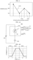
- FIG. 4A is block diagram illustrating an example of gas evaluation system 900 used for the evaluation of gas sensor 100.
- Gas evaluation system 900 illustrated in FIG. 4A includes sealed container 910 that stores therein gas sensor 100, power supply 920, and current measuring instrument 930.
- Sealed container 910 is connected to hydrogen gas cylinder 911 and argon gas cylinder 912 via introduction valves 913 and 914, respectively, and is able to discharge the internal gas via exhaust valve 915.
- power supply 920 is a power supply circuit that constantly applies a predetermined voltage across first electrode 104 and second electrode 105.
- Current measuring instrument 930 is a measurement circuit that measures the current flowing through gas-sensitive insulating film 103 when a predetermined voltage is applied across first electrode 104 and second electrode 105 in gas sensor 100.
- FIG. 4B is a graph showing an evaluation example of gas sensor 100.
- the horizontal axis indicates the time (a.u.) and the vertical axis indicates the current (a.u.) flowing between first electrode 104 and second electrode 105.
- nitrogen gas is introduced into sealed container 910 in which gas sensor 100 is placed.
- argon gas is switched to hydrogen gas.
- the hydrogen gas is further switched to nitrogen gas.
- FIG. 4B shows the result at this time, and the horizontal axis indicates three periods in which the former argon introduction (Step S201), the hydrogen introduction (Step S202), and the latter argon introduction (Step S203) are performed. It can be seen that the current starts to increase after the introduced gas is switched from argon gas to hydrogen gas. In addition, it can be seen that the current starts to decrease after the introduced gas is switched from hydrogen gas to argon gas.
- gas sensor 100 in which local region 107 is set to a high-resistance state by applying a predetermined voltage (potential difference) across first electrode 104 and second electrode 105 in advance is used.
- a gas sensing voltage of 0.6 V is applied across first electrode 104 and second electrode 105, and the current of from 10 ⁇ A to 20 ⁇ A flows between first electrode 104 and second electrode 105 in a state in which the hydrogen gas is detected. Therefore, according to gas sensor 100, it can be seen that the hydrogen-containing gas can be monitored with extremely small electricity consumption of from 0.006 mW to 0.012 mW
- the detection mechanism of the hydrogen gas in gas sensor 100 is assumed to be as follows.
- the hydrogen atoms When the hydrogen-containing gas comes into contact with second electrode 105, the hydrogen atoms are dissociated from the hydrogen-containing gas by the catalysis caused by second electrode 105. In order to maintain an equilibrium state, the dissociated hydrogen atoms are diffused in second electrode 105 and reach local region 107 in the region of gap 106.
- the hydrogen atoms that have formed the water molecules in local region 107 returns to second electrode 105 by a reduction reaction. Meanwhile, the oxygen that has formed the water molecules becomes bound to the oxygen defect, thereby reducing the degree of oxygen deficiency.
- the detectable gas is not limited to hydrogen gas, and the abovementioned operation occurs for various types of hydrogen-containing gas such as methane and alcohol, for example.
- gas sensor 100 As described above, according to gas sensor 100 according to this embodiment, a detecting element with excellent power-saving properties capable of generating heat with only the current for sensing the resistance state and detecting the hydrogen-containing gas without heating with a separate heater can be obtained.
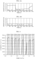
- FIG. 5A is a graph showing the resistance measurement result after the gas is introduced when second electrode 105 of gas sensor 100 is Pt.
- FIG. 5B is a graph showing the resistance measurement result after the gas is introduced when second electrode 105 of gas sensor 100 is TiN.
- gas sensor 100 is arranged in a sealed container, and measurement is performed by introducing air atmosphere (Air) into the sealed container from time point 0 s to time point 300 s, introducing argon atmosphere (Ar) into the sealed container from time point 300 s to time point 900 s, introducing hydrogen/argon gas (Ar-H 2 ) in addition to argon atmosphere (Ar) into the sealed container from time point 900 s to time point 1500 s, introducing argon atmosphere (Ar) into the sealed container again from time point 1,500 s to time point 2,100 s, and performing vacuum drawing (Vac) of the sealed container from time point 2,100 s to time point 2,700 s.
- Air air atmosphere
- Ar argon atmosphere
- Ar-H 2 hydrogen/argon gas
- Vac vacuum drawing
- the resistance of gas sensor 100 decreases by about three digits when the hydrogen/argon gas is introduced to the argon atmosphere (the period of Ar+Ar-H 2 shown in FIG. 5A ). Further, by completely removing hydrogen gas by performing vacuum drawing on sealed container 910 (the period of Vac shown in FIG. 5A ), the resistance of gas sensor 100 recovers to the original value again. Meanwhile, as shown in FIG. 5A , when the material of second electrode 105 is Pt that causes catalysis, the resistance of gas sensor 100 decreases by about three digits when the hydrogen/argon gas is introduced to the argon atmosphere (the period of Ar+Ar-H 2 shown in FIG. 5A ). Further, by completely removing hydrogen gas by performing vacuum drawing on sealed container 910 (the period of Vac shown in FIG. 5A ), the resistance of gas sensor 100 recovers to the original value again. Meanwhile, as shown in FIG.
- FIG. 6 is a graph showing the measurement result of the gas introduction flow rate and the sensor output current of gas sensor 100. Note that the shaded parts in FIG. 6 indicate a time zone in which the hydrogen gas is introduced, and the introduced gas flow rate is the value described on the upper part of FIG. 6 .
- the output current of gas sensor 100 greatly increases by introducing the hydrogen/argon gas into the sealed container, and the output current of gas sensor 100 decreases by stopping the hydrogen/argon gas introduction. Further, it can be understood from FIG. 6 that the rising of the current measurement value becomes faster in accordance with the increase in the gas flow rate of the hydrogen/argon gas to be introduced. With use of the relationship, the hydrogen gas concentration can be measured by measuring the time until the current reaches a predetermined current from the introduction of the hydrogen/argon gas.
- FIG. 7 is a graph showing the measurement result of the gas introduction flow rate and the resistance in accordance with whether there is forming of gas sensor 100. Note that the shaded parts in FIG. 7 indicate time zones in which the hydrogen gas is introduced, and the introduced gas flow rate in each time zone is the value described on the upper portion of FIG. 7 .
- the resistance decreases by three digits by the introduction of the hydrogen/argon gas.
- the time until the state reaches a low-resistance state becomes shorter as the gas flow rate of the hydrogen/argon gas increases.
- the resistance decreases by the introduction of the hydrogen/argon gas also in gas sensor 100 without the forming process indicated by dotted line R2 in FIG. 7 , but the change does not go further than a change by about one digit. This is assumed to be caused by the state of the local region being different from the case with the forming process and the oxygen lacking density being low in the local region of the gas sensor without the forming.
- the gas detection sensitivity of gas sensor 100 can be adjusted by controlling the state of the local region, that is, the oxygen lacking density in the local region by the forming process.
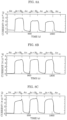
- FIG. 8A to FIG. 8C are graphs showing the measurement result of the gas sensing voltage and the output current of gas sensor 100.
- FIG. 8A to FIG. 8C each show the output current when gas sensing voltage V READ is 100 mV, 10 mV, and 1 mV, respectively.
- FIG. 8A to FIG. 8C alternately repeat the period in which the hydrogen/argon gas of 0.5 L/min is introduced (the period of Ar+H 2 shown in FIG. 8A to FIG. 8C ) and the period in which air is introduced (the period of Air shown in FIG. 8A to FIG. 8C ) every 30 s.
- gas sensing voltage V READ when gas sensing voltage V READ is 100 mV, the resistance decreases and a current of 35 nA is sensed when the hydrogen/argon gas is introduced to gas sensor 100. Further, when gas sensing voltage V READ is reduced to 10 mV and 1 mV, the detected current decreases to 1/10 and 1/100, respectively, in accordance with the decrease in voltage as shown in FIG. 8B and FIG. 8C .
- the gas sensing voltage has little effect on the rising situation of the current after the hydrogen/argon gas is introduced. Therefore, in gas sensor 100, gas sensing voltage V READ can be reduced to a voltage of at least about 1 mV. In other words, the electricity consumption does not necessarily need to be about 100 mW as in the gas sensing device of the related art when the gas detecting element is heated to 100 °C or more, and energy conservation and long life can be expected at the same time.
- gas sensor 100 the presence of gas can be sensed with a low gas sensing voltage and at high speed. Therefore, the gas containing hydrogen atoms can be sensed with low electricity consumption and at high speed.
- FIG. 9 is a cross-sectional view illustrating a configuration example of gas sensor 200 according to Embodiment 2. Only the differences from gas sensor 100 according to Embodiment 1 are described below.
- Gas sensor 200 illustrated in FIG. 9 includes substrate 201, interlayer insulating film 202, gas-sensitive insulating film 203, first electrode 204, second electrode 205, and gap 206.
- insulator layer 208 is formed so as to cover first electrode 204, second electrode 205, and gas-sensitive insulating film 203 in gap 206. Note that insulator layer 208 only needs to be formed so as to at least cover gas-sensitive insulating film 203 in gap 206.
- Insulator layer 208 has a function of selectively causing hydrogen gas to pass therethrough (in other words, a function of causing the hydrogen gas to easily pass therethrough but not causing gas other than the hydrogen gas to easily pass therethrough). As a result, gas-sensitive insulating film 203 does not directly come into contact with gas, and hence it is effective in terms of improving the reliability of the sensor operation. Note that insulator layer 208 is formed by a silicon oxide film, for example.
- the function of insulator layer 208 for selectively causing hydrogen gas to pass therethrough depends on the film thickness of insulator layer 208.
- the film thickness of insulator layer 208 is preferred to be a film thickness by which the number of hydrogen molecules necessary for changing the resistance of the metal oxide layer are transmitted within a predetermined amount of time.
- the thickness of insulator layer 208 for not causing gas other than the hydrogen gas to pass therethrough may be 8.5 nm, for example, as described below.
- the lower limit of the thickness of insulator layer 208 may be 0.5 nm, for example, on the basis of the disclosure of NPL 5.
- FIG. 10A is a cross-sectional view of structure body 700 having a double gate-silicon on insulator (DG-SOI) structure described in NPL 5.
- Structure body 700 is contemplated as a structure body obtained by forming silicon oxide films 702 and 703 on upper and lower main surfaces of silicon substrate 701, and further depositing polysilicon films 704 and 705 on exposed surfaces of silicon oxide films 702 and 703.
- a thickness ts of silicon substrate 701 and a thickness tg of each polysilicon film are 5 nm, and a thickness tox of each of silicon oxide films 702 and 703 is controlled.
- FIG. 10B shows a result obtained by calculating the existence probability (P s1 to P s4 ) of the electrons in silicon substrate 701 by changing the thickness tox of each of silicon oxide films 702 and 703 in structure body 700.
- P s1 to P s4 correspond to the energy levels of the electrons in silicon substrate 701 in the DG-SOI structure illustrated in FIG. 10A , and indicate the existence probability of the electrons on the orbits thereof.
- the existence probability of the electrons in silicon substrate 701 becomes significantly smaller than 1.
- the electrons cannot substantially pass through a silicon oxide film of which film thickness tox is 0.5 nm or more. Therefore, by depositing a silicon oxide film having a thickness of 0.5 nm or more on second electrode 205, the electrons in second electrode 205 can be prevented from interacting with the molecules existing on the outside. As a result, external gas is not adsorbed by the surface of second electrode 205, and the hydrogen atoms are not dissociated from the molecules containing the hydrogen atoms at second electrode 205 that causes catalysis.
- silicon oxide film is thicker.
- silicon oxide film is too thick, it requires time for gas-sensitive insulating film 203 to cause resistance change by the hydrogen molecules that have passed through the silicon oxide film and reached second electrode 205. Therefore, there is an upper limit to the thickness of the silicon oxide film in order to realize a desired response time (for example, within one second as a standard desired for the gas sensor used for a fuel cell vehicle).
- the number of hydrogen molecules that need to reach second electrode 205 in order to cause gas-sensitive insulating film 203 set to be in a high-resistance state to transition to a low-resistance state depends on the material and the size of gas sensor 200. In a specific example of the gas sensor examined by the inventors of the present disclosure, the number is 2,200. In other words, in the gas sensor, at least 2,200 hydrogen molecules are required to pass through the silicon oxide film and reach second electrode 205 within one second.
- n N O A B T ⁇ 2 ⁇ M erfc x 1 2 D SiO 2 L
- FIG. 10C is a graph showing the result obtained by calculating the relationship between the number of hydrogen molecules transmitted through the silicon oxide film in one second and the film thickness of the silicon oxide film when hydrogen molecule density N 0 is 0.1% on the basis of Expression 1.
- the dotted line indicates 2,200 that is an example of the number of hydrogen molecules necessary for the resistance change of gas-sensitive insulating film 203. It can be seen from FIG. 10C that 2,200 hydrogen molecules necessary for the resistance change reach the surface of second electrode 205 within one second when the thickness of silicon oxide film is 8.5 nm or less.
- the thickness tox of the silicon oxide film may be within a desired range.
- the leaking of the hydrogen molecules to polysilicon films 704 and 705 can be suppressed.
- 2,200 hydrogen molecules necessary for the resistance change can be caused to reach the surface of second electrode 205 within a desired response time.
- the thickness tox of the silicon oxide film may be 0.5 nm or more and 8.5 nm or less for the gas sensor used for the fuel cell vehicle.
- the leaking of the hydrogen molecules to polysilicon films 704 and 705 can be suppressed.
- 2,200 hydrogen molecules necessary for the resistance change can be caused to reach the surface of second electrode 205 within a desired response time (within one second for the gas sensor used for the fuel cell vehicle).
- FIG. 11A, FIG. 11B , and FIG. 11C are cross-sectional views illustrating configuration examples of gas sensors according to Embodiment 3.
- FIG. 11D shows an exemplary gas sensor which is not according to the present invention. Only parts of gas sensors 300, 400, 500, and 600 according to this embodiment that are different from gas sensor 100 according to Embodiment 1 are described below.
- gas-sensitive insulating film 303 is formed in a region that is larger than first electrode 304 and second electrode 305.
- substrate 101 and interlayer insulating film 102 are similar to substrate 101 and interlayer insulating film 102 of gas sensor 100 illustrated in Embodiment 1, and hence the description thereof is omitted.
- first electrode 304 and second electrode 305 of the minimum width need to be arranged on gas-sensitive insulating film 303. Therefore, local region 307 can be efficiently formed on gas-sensitive insulating film 303. Therefore, gas sensor 300 can be formed by efficiently arranging first electrode 304 and second electrode 305.
- Gas sensor 400 illustrated in FIG. 11B has a structure in which, on interlayer insulating film 102 formed on substrate 101, gas-sensitive insulating film 403 is in contact with an end surface of at least one of first electrode 404 and second electrode 405.
- one of first electrode 404 and second electrode 405 is arranged at the same layer level as gas-sensitive insulating film 403, and the other is arranged on gas-sensitive insulating film 403.
- a region in which gas-sensitive insulating film 403 is exposed is provided between a region in which first electrode 404 is arranged and a region in which second electrode 405 is arranged.
- substrate 101 and interlayer insulating film 102 are similar to substrate 101 and interlayer insulating film 102 of gas sensor 100 described in Embodiment 1, and hence the description thereof is omitted.
- local region 407 is formed between an end surface of first electrode 404 or second electrode 405 arranged at the same layer level as gas-sensitive insulating film 403 and second electrode 405 or first electrode 404 arranged on gas-sensitive insulating film 403.
- the surface of gas-sensitive insulating film 403 other than the part in which local region 407 is desired to be formed is covered with first electrode 404 or second electrode 405. Therefore, the reaction of gas-sensitive insulating film 403 with other gas in parts other than the part in which local region 407 is formed can be suppressed.
- Gas sensor 500 illustrated in FIG. 11C has a structure in which, on interlayer insulating film 102 formed on substrate 101, gas-sensitive insulating film 503 in contact with end surfaces of both of first electrode 504 and second electrode 505.
- first electrode 504 and second electrode 505 are arranged at the same layer level as gas-sensitive insulating film 503. Further, a region in which gas-sensitive insulating film 503 is exposed is provided between a region in which first electrode 504 is arranged and a region in which second electrode 505 is arranged in planar view.
- substrate 101 and interlayer insulating film 102 are similar to substrate 101 and interlayer insulating film 102 of gas sensor 100 described in Embodiment 1, and hence the description thereof is omitted.
- Gas sensor 600 illustrated in FIG. 11D is not part of the claimed invention and includes two layers, that is, first oxide layer 603A and second oxide layer 603B as the gas-sensitive insulating film on interlayer insulating film 102 formed on substrate 101.
- the gas-sensitive insulating film may be formed by two or more layers.
- Substrate 101 and interlayer insulating film 102 are similar to substrate 101 and interlayer insulating film 102 of gas sensor 100 described in Embodiment 1, and hence the description thereof is omitted.
- First oxide layer 603A and second oxide layer 603B are laminated on a part of interlayer insulating film 102 in the stated order.
- first electrode 604 is formed on interlayer insulating film 102 so as to be continuous to first oxide layer 603A.
- second electrode 605 is formed on at least a part of second oxide layer 603B.
- local region 607 arranged in contact with second electrode 605 and not in contact with first electrode 604 is included in first oxide layer 603A and second oxide layer 603B.
- At least a part of local region 607 is formed in second oxide layer 603B, and the degree of oxygen deficiency of local region 607 reversibly changes in accordance with the application of an electrical pulse. It is conceived that local region 607 includes a filament formed by oxygen defection sites.
- gas-sensitive insulating film 603 has a laminated structure at least including first oxide layer 603A including first metal oxide and second oxide layer 603B including second metal oxide. Further, first oxide layer 603A is arranged between first electrode 604 and second oxide layer 603B, and second oxide layer 603B is arranged between first oxide layer 603A and second electrode 605. The thickness of second oxide layer 603B may be thinner than the thickness of first oxide layer 603A. In this case, a structure in which local region 607 is not in contact with first electrode 604 described below can be easily formed. The resistance of second oxide layer 603B is higher than the resistance of first oxide layer 603A, and hence most voltage applied to gas-sensitive insulating film 603 is applied to second oxide layer 603B.
- gas-sensitive insulating film 603 is not limited to the case where the metal forming first oxide layer 603A and second oxide layer 603B is the same, and the metal may be different. That is, first oxide layer 603A and second oxide layer 603B may be different metal oxides.
- the oxygen content is in a corresponding relationship with the degree of oxygen deficiency. That is, when the oxygen content of the second metal oxide is larger than the oxygen content of the first metal oxide, the degree of oxygen deficiency of the first metal oxide is smaller than the degree of oxygen deficiency of the second metal oxide.
- the degree of oxygen deficiency of local region 607 is larger than the degree of oxygen deficiency of second oxide layer 603B, and is different from the degree of oxygen deficiency of first oxide layer 603A.
- local region 607 is formed in at least one of first oxide layer 603A and second oxide layer 603B by applying an initial breakdown voltage across first electrode 604 and second electrode 605.
- an initial breakdown voltage across first electrode 604 and second electrode 605.
- the current easily flows through a region in which the distance between first electrode 604 and second electrode 605 is short. Therefore, by the initial breakdown, local region 607 is formed in a region that is in contact with second electrode 605, passes through second oxide layer 603B, partially enters first oxide layer 603A, and is not in contact with first electrode 604.
- Fuel cell vehicle 800 according to Embodiment 4 includes any of the gas sensors described in Embodiment 1 to Embodiment 3 described above. Fuel cell vehicle 800 detects the hydrogen gas in the vehicle with the gas sensor.
- FIG. 12 is a side view illustrating a configuration example of fuel cell vehicle 800 according to this embodiment.
- Fuel cell vehicle 800 includes passenger compartment 810, luggage compartment 820, gas tank compartment 830, fuel tank 831, gas sensor 832, piping 840, fuel cell compartment 850, fuel cell 851, gas sensor 852, motor compartment 860, and motor 861.
- Fuel tank 831 is provided in gas tank compartment 830, and retains hydrogen gas as the fuel gas.
- Gas sensor 832 detects fuel gas leakage in gas tank compartment 830.
- Fuel cell 851 is formed as a fuel cell stack by stacking cells each including a fuel electrode, an air electrode, and an electrolyte as a base unit. Fuel cell 851 is provided in fuel cell compartment 850. The hydrogen gas in fuel tank 831 is transmitted into fuel cell 851 in fuel cell compartment 850 through piping 840, and electricity is generated by causing the hydrogen gas and oxygen gas in the atmosphere to react with each other in fuel cell 851. Gas sensor 852 detects the leakage of hydrogen gas in fuel cell compartment 850.
- Motor 861 is provided in motor compartment 860, rotates with the electricity generated by fuel cell 851, and causes fuel cell vehicle 800 to travel.
- hydrogen gas can be detected with extremely small electricity consumption of about 0.01 mW, for example. Therefore, the leakage of hydrogen gas can be constantly monitored without greatly increasing the standby power of the fuel cell vehicle by utilizing the excellent power-saving properties of the gas sensor.
- a predetermined voltage may be constantly applied to gas sensors 832 and 852 regardless of the operation state of an ignition key in fuel cell vehicle 800, and it may be determined whether there is hydrogen gas on the outside of fuel tank 831 in gas tank compartment 830 and the outside of fuel cell 851 in fuel cell compartment 850 on the basis of the current amount flowing through gas sensors 832 and 852.
- the abovementioned gas sensor may further include a measurement circuit that measures the current flowing through the sensitive insulating film when a predetermined voltage is applied across the first electrode and the second electrode.
- a power supply circuit that constantly applies a predetermined voltage across the first electrode and the second electrode may be further included.
- a highly-convenient gas sensor can be obtained as a module part including a measurement circuit and a power supply circuit.
- the gas sensor according to this disclosure is useful in a fuel cell vehicle, a hydrogen station, a hydrogen plant, and the like, for example.
Landscapes
- Chemical & Material Sciences (AREA)
- Life Sciences & Earth Sciences (AREA)
- Health & Medical Sciences (AREA)
- Chemical Kinetics & Catalysis (AREA)
- Electrochemistry (AREA)
- Engineering & Computer Science (AREA)
- Analytical Chemistry (AREA)
- Biochemistry (AREA)
- General Health & Medical Sciences (AREA)
- General Physics & Mathematics (AREA)
- Immunology (AREA)
- Pathology (AREA)
- Physics & Mathematics (AREA)
- Manufacturing & Machinery (AREA)
- Sustainable Development (AREA)
- Sustainable Energy (AREA)
- General Chemical & Material Sciences (AREA)
- Molecular Biology (AREA)
- Microelectronics & Electronic Packaging (AREA)
- Combustion & Propulsion (AREA)
- Food Science & Technology (AREA)
- Medicinal Chemistry (AREA)
- Investigating Or Analyzing Materials By The Use Of Fluid Adsorption Or Reactions (AREA)
- Investigating Or Analyzing Materials By The Use Of Electric Means (AREA)
- Fuel Cell (AREA)
Description
- This disclosure relates to a gas sensor including a gas-sensitive body layer, and the like. The gas sensor of the present invention is defined in
claim 1 and its dependent claims. Claim 14 refers to a fuel cell vehicle comprising the gas sensor. - Hydrogen energy has been recently gathering attention as a solution to environmental problems. As specific measures therefore, fuel cell vehicles using hydrogen as fuel have been starting to be sold. Accordingly, the development of infrastructures including hydrogen stations is also gathering attention. In order to realize a hydrogen energy-based society, it is urgently necessary to develop laws, for example, reconsider safety standards. Further, the importance of hydrogen gas sensing devices is also increasing in the safety aspect in terms of tangible factors.
- As the types of the hydrogen gas sensing devices, types such as a contact combustion type, a semiconductor type, and a gas heat conduction type are used. The contact combustion type is a type using catalytic combustion heat obtained by a catalyst (Pt, Pd, and the like) of combustible gas. The semiconductor type is a type using the change in electrical conductivity caused by gas adsorption on a metal oxide semiconductor surface. The gas heat conduction type is a type using the difference in heat conduction between target gas and standard gas.
- In addition, in a gas sensing device of the related art, a heating heater is installed adjacent to a gas detecting element in order to increase the detection sensitivity of the gas detecting element (for example,
PTL 1,PTL 2, andNPL 1 to NPL 4). In the gas sensing device, the ambient temperature of the gas detecting element is normally maintained to be 100 °C or more at the time of measurement by the heating heater. -
- PTL 1:
Japanese Unexamined Patent Application Publication No. S59-58348 - PTL 2:
Japanese Patent No. 5352032 -
- NPL 1: Sensors and Actuators A 172(2011) 9-14
- NPL 2: IEEE SENSORS 2010 Conference, 2145-2148
- NPL 3: Journal of The Surface Finishing Society of Japan Vol. 57, No. 4, 2006, pp 267-270
- NPL 4: Journal of The Hydrogen Energy Systems Society of Japan Vol. 30, No. 2 (2005), pp 35-40
- NPL 5: B. Majkusiak and et al "THEORETICAL LIMIT FOR THE SiO2 THICKNESS IN SILICON MOS DEVICES" D. Flandre et al. (eds.), Science and Technology of Semiconductor-On-Insulator Structures and Devices Operating in a Harsh Environment, 309-320.c 2005 Kluwer Academic Publishers. Printed in the Netherlands.
- A . Mozalev et al, Formation and gas-sensing properties of a porous-alumina-assisted 3-D niobium-oxide nanofilm, Sensors and Actuators B: Chemical, Volume 229, 2016, Pages 587-598 discloses a 3-dimensional metal/oxide/metal nanofilm composed of an NbO2 layer, 200 nm thick, with upright-standing Nb2O5 nanocolumns which work as semiconducting nano-channels, assembled between two parallel metal electrodes, whose resistivity measured along the columns is greatly impacted by the surface and interface reactions.
- However, as in the gas sensing device of the related art, when the gas detecting element is heated to 100 °C or more, an electricity consumption of about 100 mW is necessary at minimum. Therefore, when the gas sensing device is used in a constant ON state, the electricity consumption becomes extremely high. In addition, in order to sense the hydrogen gas, hydrogen atoms generated when the hydrogen gas is decomposed at an electrode surface need to be diffused in the electrode and reach a gas-sensitive body. At this time, the gas sensing speed becomes faster when the speed at which the hydrogen atoms reach the gas-sensitive body layer is fast. Therefore, the improvement of the gas sensing speed in a low temperature operation is a challenge.
- This disclosure has been made to solve the abovementioned problem, and an object thereof is to provide a gas sensor capable of sensing gas containing hydrogen atoms with low electricity consumption and at high speed, and the like.
- In accordance with an aspect of the present disclosure, there is provided a gas sensor according to
claim 1. - In accordance with another aspect of the present disclosure, there is provided a fuel cell vehicle as defined in claim 14.
- According to this disclosure, the gas sensor capable of sensing the gas containing hydrogen atoms with low electricity consumption and at high speed, and the like can be provided.
-
-
FIG. 1 is a cross-sectional view illustrating an example of the configuration of a gas sensor according toEmbodiment 1. -
FIG. 2A is a cross-sectional view illustrating an example of a manufacturing method of the gas sensor according toEmbodiment 1. -
FIG. 2B is a cross-sectional view illustrating an example of the manufacturing method of the gas sensor according toEmbodiment 1. -
FIG. 2C is a cross-sectional view illustrating an example of the manufacturing method of the gas sensor according toEmbodiment 1. -
FIG. 2D is a cross-sectional view illustrating an example of the manufacturing method of the gas sensor according toEmbodiment 1. -
FIG. 3 is a graph showing the state of a gas sensing element according toEmbodiment 1. -
FIG. 4A is a diagram illustrating a gas evaluation system of the gas sensor according toEmbodiment 1. -
FIG. 4B is a graph showing an evaluation result of the gas sensor according toEmbodiment 1. -
FIG. 5A is a graph showing the resistance measurement result after the gas is introduced when a second electrode of the gas sensor according toEmbodiment 1 is Pt. -
FIG. 5B is a graph showing the resistance measurement result after the gas is introduced when the second electrode of the gas sensor is TiN (not according to the present invention). -
FIG. 6 is a graph showing the measurement result of the gas introduction flow rate and the output current of the gas sensor according toEmbodiment 1. -
FIG. 7 is a graph showing the measurement result of the gas introduction flow rate and the resistance in accordance with whether there is forming of the gas sensor according toEmbodiment 1. -
FIG. 8A is a graph showing the measurement result of the gas sensing voltage and the output current of the gas sensor according toEmbodiment 1. -
FIG. 8B is a graph showing the measurement result of the gas sensing voltage and the output current of the gas sensor according toEmbodiment 1. -
FIG. 8C is a graph showing the measurement result of the gas sensing voltage and the output current of the gas sensor according toEmbodiment 1. -
FIG. 9 is a cross-sectional view illustrating an example of the configuration of a gas sensor according toEmbodiment 2. -
FIG. 10A is a cross-sectional view illustrating an example of the configuration of a double gate-silicon on insulator (DG-SOI) structure. -
FIG. 10B is a graph showing the relationship between the existence probability of electrons and the thickness of a silicon oxide film. -
FIG. 10C is a graph showing the relationship between the number of hydrogen molecules transmitted through the silicon oxide film in one second and the film thickness of the silicon oxide film. -
FIG. 11A is a cross-sectional view illustrating an example of the configuration of a gas sensor according toEmbodiment 3. -
FIG. 11B is a cross-sectional view illustrating an example of the configuration of the gas sensor according toEmbodiment 3. -
FIG. 11C is a cross-sectional view illustrating an example of the configuration of the gas sensor according toEmbodiment 3. -
FIG. 11D is a cross-sectional view illustrating an exemplary configuration of a gas sensor. The example shown is not according to the present invention. -
FIG. 12 is a side view illustrating an example of the configuration of a fuel cell vehicle according toEmbodiment 4. - First, the underlying knowledge of this disclosure is described.
- As the result of intensive studies, the inventors of the present disclosure have found that the gas sensor of the related art has the following problems.
- As the hydrogen gas sensing device, the contact combustion type, the semiconductor type, and the gas heat conduction type have been hitherto mainly used in Japan. The contact combustion type is a sensing device using catalytic combustion heat obtained by a catalyst (Pt, Pd, and the like) of combustible gas. In the contact combustion-type hydrogen gas sensing device, as the concentration of the hydrogen gas rises, the element temperature rises due to combustion, and the resistance increases. The sensor output is linear with respect to the gas concentration, but there is a problem in gas selectivity.
- The semiconductor-type hydrogen gas sensing device uses the change in electrical conductivity caused by gas adsorption on a metal oxide semiconductor surface. In the semiconductor-type hydrogen gas sensing device, the sensor output is logarithmic with respect to the gas concentration, and hence the sensitivity is high even in low-concentration regions.
- The gas heat conduction-type hydrogen gas sensing device uses the difference in heat conduction between target gas and standard gas. In the gas heat conduction-type hydrogen gas sensing device, the heat conductivity of the hydrogen gas is higher than other combustible gas. Therefore, the gas heat conduction-type hydrogen gas sensing device is suitable for sensing especially in high-concentration regions.
- A hydrogen gas sensing device having a MIM structure obtained by laminating an insulating film and a metal film described in
PTL 1 is classified as the semiconductor type. In the hydrogen gas sensing device having a MIM structure, an insulating film obtained by adding a predetermined amount of palladium and glass to tantalum pentoxide (Ta2O5) is used as the gas-sensitive insulating film, and Pt is used as the upper and lower sandwiching metal electrodes. However, there is no description on the detailed mechanism. Thus, description can be made as follows when a phenomenon similar to that of the mechanism described inNPL 1 relating to a gas sensing device (Pt-Ta2O5-Si) using a MIS structure is assumed to be caused. - When gas containing hydrogen gas comes into contact with a surface of Pt that is a catalytic metal, for example, the hydrogen gas is decomposed into hydrogen atoms by the catalysis of Pt. Further, the decomposed hydrogen atoms are diffused in a Pt electrode and reach tantalum pentoxide (Ta2O5) that is the gas-sensitive body. The hydrogen atoms that have reached tantalum pentoxide (Ta2O5) reduce tantalum pentoxide (Ta2O5) and are oxidized in accordance with the chemical reaction formula below, thereby becoming water.
Ta2O5+2xH →xH2O+Ta2O5-x
- At this time, it is conceived that the flow of the current is facilitated because of an oxygen defect in tantalum pentoxide formed by the hydrogen atom taking an oxygen atom from tantalum pentoxide (Ta2O5) in the gas-sensitive insulating film.
- Meanwhile, when the gas containing hydrogen gas is removed from the Pt surface, it is conceived that a reversed process in accordance with the following chemical reaction formula:
xH2O+Ta2O5-x →Ta2O5+2xH
occurs, the oxygen defect in tantalum pentoxide is removed, and it becomes difficult for the current to flow. By the mechanism as above, it is conceived that the MIM structure in which an insulating film obtained by adding a predetermined amount of palladium and glass to tantalum pentoxide (Ta2O5) is used as the gas-sensitive insulating film and Pt is used as the upper and lower metal electrodes sandwiching the gas-sensitive insulating film functions as a gas sensing device that senses the gas containing hydrogen atoms. - Now, when the hydrogen atoms are dissociated by Pt that is a catalytic metal, the rate of the hydrogen atoms to be dissociated from molecules containing the hydrogen atoms by the catalysis is proportional to the temperature rise. In other words, it is conceived that the detection sensitivity of the gas increases as the gas detecting element temperature rises. In the gas sensing device of the related art, in order to improve the detection sensitivity of the gas containing hydrogen atoms, the gas detecting element at the time of measurement is heated to 100 °C or more.
- For example, in the gas sensing device having a MIM structure described in
PTL 1, the gas detecting element temperature is raised to 400 °C by applying a predetermined voltage to a heating heater provided adjacent to the gas detecting element. - Not only in the gas sensing device having a MIM structure but also in the gas sensing device having a MIS structure using the catalysis of metal, a heating heater is installed adjacent to the gas detecting element and is normally used by maintaining the ambient temperature at 100 °C or more. For example, in the gas sensing device described in
NPL 1, a temperature of 100 °C or more is needed when the MIS structure is used as a diode. In addition, a gas sensing device described inNPL 2 using a MIS structure as a transistor is operated while setting the ambient temperature of the gas detecting element to 115 °C. - In addition, in a contact combustion-type gas sensing device described in
NPL 3 using the catalysis of metal, the gas detecting element is heated to from 200 °C to 300 °C at the time of operation. - Further, in a hot-wire semiconductor-type gas sensing device and a gas heat conduction-type gas sensing device described in
NPL 4 that do not use the catalysis of metal, the gas detecting element is heated to 100 °C or more for both types. - However, when the gas detecting element is heated to 100 °C or more, an electricity consumption of about 100 mW is necessary at minimum. Therefore, when the gas sensing device is used in a constant ON state, the electricity consumption becomes extremely high. In addition, in order to sense the hydrogen gas, hydrogen atoms generated by decomposing the hydrogen gas at an electrode surface need to be diffused in the electrode and reach the gas-sensitive body. At this time, the gas sensing speed of the gas sensing device improves as the speed at which the hydrogen atoms reach the gas-sensitive body becomes faster. Therefore, the improvement of the gas sensing speed in a low temperature operation is a challenge for the gas sensing device.
- Thus, in this disclosure, a gas sensor capable of sensing gas containing hydrogen atoms with low electricity consumption and at high speed is realized by a gas sensor having the following configuration.
- That is, the gas sensor according to this embodiment is a gas sensor as follows. In the gas sensor, a first electrode and a second electrode are arranged on a substrate in an opposed manner so as to form a gap, and at least a part of a gas-sensitive body layer formed by metal oxide is exposed via the gap. Further, the gas-sensitive body layer is in contact with the second electrode and includes a local region having a degree of oxygen deficiency larger than that of the metal oxide layer in the gas-sensitive body layer. Further, the resistance of the metal oxide decreases when gas molecules containing hydrogen atoms are detected. The second electrode causes catalysis that dissociates the hydrogen atoms from the gas molecules containing the hydrogen atoms. The resistance of the metal oxide layer decreases as the hydrogen atoms are dissociated from the gas molecules in a part of the second electrode in contact with the local region and the dissociated hydrogen atoms are bound to oxygen atoms in the local region of the metal oxide layer.
- In a configuration in which at least one of the first electrode and the second electrode is in contact with the local region having a degree of oxygen deficiency larger than that of the metal oxide layer, the current flowing between the first electrode and the second electrode is concentrated on the local region having a larger degree of oxygen deficiency. As a result, the temperature of the local region can be raised with less current. When the temperature of the local region rises, the temperature of the surface of the second electrode also rises. In the second electrode that causes catalysis, the rate of the dissociation of the hydrogen atoms from the gas molecules containing the hydrogen atoms increases in accordance with the temperature rise.
- Hereinafter, certain exemplary embodiments of the present disclosure are described in greater detail with reference to the accompanying Drawings.
- In the drawings, elements regarding substantially identical structures, processing, and effects are assigned with a same reference sign, and explanation of such substantially identical elements is not repeated. Numerical values, materials, film forming methods, and the like described in the following embodiments are merely examples for explaining the embodiments according to the present disclosure in more detail, and are not intended to limit the present disclosure. Connection relationships between constituent elements described in the following embodiments are merely examples for explaining the embodiments according to the present disclosure in more detail, and connection relationships for achieving the functions of the present disclosure are not limited to the described relationships. Furthermore, the present disclosure is defined by the claims. Therefore, among the constituent elements in the following embodiments, constituent elements that are not described in independent claims that show the most generic concept of the present disclosure are described as elements constituting more desirable configurations, although such constituent elements are not necessarily required to achieve the object of the present disclosure.
-
FIG. 1 is a cross-sectional view illustrating an example of the configuration ofgas sensor 100 according toEmbodiment 1. -
Gas sensor 100 according to this embodiment includessubstrate 101,interlayer insulating film 102 formed onsubstrate 101, gas-sensitiveinsulating film 103 that is a metal oxide layer formed oninterlayer insulating film 102,first electrode 104,second electrode 105, andgap 106 formed by arrangingfirst electrode 104 andsecond electrode 105 to be opposed to each other.First electrode 104 is formed on gas-sensitiveinsulating film 103, andsecond electrode 105 is formed on gas-sensitiveinsulating film 103 so as to havegap 106 betweenfirst electrode 104 andsecond electrode 105, and further disposed on the first electrode (104). In addition, ingap 106 formed by arrangingfirst electrode 104 andsecond electrode 105 to be opposed to each other, a part of gas-sensitiveinsulating film 103 is exposed. - Note that, as described below,
first electrode 104 andsecond electrode 105 are not limited to be formed on gas-sensitiveinsulating film 103, and may be formed abovesubstrate 101 at the same layer level as gas-sensitiveinsulating film 103. - Gas-sensitive
insulating film 103 is a layer in which the resistance reversibly changes on the basis of an electrical signal provided betweenfirst electrode 104 andsecond electrode 105. For example, gas-sensitiveinsulating film 103 is a layer that reversibly transitions to a high-resistance state and a low-resistance state in accordance with a voltage difference provided betweenfirst electrode 104 andsecond electrode 105. - Now, gas-sensitive
insulating film 103 is arranged in contact withsecond electrode 105, and haslocal region 107 that is not in contact withfirst electrode 104 in the region ofgap 106 formed by arrangingfirst electrode 104 andsecond electrode 105 to be opposed to each other. Inlocal region 107, the degree of oxygen deficiency reversibly changes in accordance with the application of an electrical pulse provided betweenfirst electrode 104 andsecond electrode 105. It is conceived thatlocal region 107 includes filaments (conductive paths) formed by oxygen defection sites. - It is conceived that, in the resistance change phenomenon in gas-sensitive
insulating film 103, the resistance changes as the degree of oxygen deficiency in the filaments in very smalllocal region 107 changes when an oxidation-reduction reaction occurs inlocal region 107. - Note that, in this disclosure, the "degree of oxygen deficiency" is a rate of deficient oxygen with respect to the amount of oxygen forming the oxide having a stoichiometric composition (when there are a plurality of stoichiometric compositions, the stoichiometric composition of which resistance is the highest out of those stoichiometric compositions) in metal oxide. The metal oxide having a stoichiometric composition is more stable and has a higher resistance than metal oxide having other compositions.
- For example, when the metal is tantalum (Ta), the oxide having the stoichiometric composition according to the abovementioned definition is Ta2O5, and hence can be expressed as TaO2.5. The degree of oxygen deficiency of TaO2.5 is 0%, and the degree of oxygen deficiency of TaO1.5 is the degree of oxygen deficiency = (2.5-1.5)/2.5 = 40%. In addition, metal oxide with excess oxygen has a degree of oxygen deficiency that is a negative value. Note that, in this disclosure, unless otherwise noted, the degree of oxygen deficiency is described so as to include positive values, 0, and negative values.
- The oxide having a small degree of oxygen deficiency has a high resistance because the oxide is closer to the oxide having a stoichiometric composition, and the oxide having a large degree of oxygen deficiency has a low resistance because the oxide is closer to the metal forming the oxide.
- The "oxygen content" is a ratio of the oxygen atoms to the total number of atoms. For example, the oxygen content of Ta2O5 is a ratio (O/(Ta+O)) of the oxygen atoms to the total number of atoms, and is 71.4 atm%. Therefore, the oxygen content of the oxygen deficient-type tantalum oxide is larger than 0 and is smaller than 71.4 atm%.
- Gas-sensitive
insulating film 103 haslocal region 107. The degree of oxygen deficiency oflocal region 107 is larger than the degree of oxygen deficiency of gas-sensitiveinsulating film 103. -
Local region 107 is formed in gas-sensitiveinsulating film 103 by applying an initial breakdown voltage acrossfirst electrode 104 andsecond electrode 105. Now, the initial breakdown voltage is a voltage of which absolute value is larger than that of an application voltage applied acrossfirst electrode 104 andsecond electrode 105 in order to cause the state to reversibly transition to a high-resistance state and a low-resistance state. Note that, as the initial breakdown voltage, a voltage lower than the application voltage for causing the state to reversibly transition to the high-resistance state and the low-resistance state described above may be repeatedly applied or applied for a predetermined amount of time. By the initial breakdown,local region 107 in contact withsecond electrode 105 andfirst electrode 104 is formed. - In this disclosure, a local region means a region out of gas-sensitive
insulating film 103 through which the current dominantly flows when voltage is applied acrossfirst electrode 104 andsecond electrode 105. Note thatlocal region 107 means a region including a set of a plurality of filaments (conductive paths) formed in gas-sensitiveinsulating film 103. That is, the resistance change in gas-sensitiveinsulating film 103 is realized throughlocal region 107. Therefore, when a drive voltage is applied to gas-sensitiveinsulating film 103, the current dominantly flows throughlocal region 107 including the filaments. - In addition,
local region 107 is a resistance change layer that reversibly transitions to a high-resistance state and a low-resistance state on the basis of the voltage difference provided betweenfirst electrode 104 andsecond electrode 105.Local region 107 may be in either of the high-resistance state and the low-resistance state. In both states, the state changes to a state with a lower resistance when the gas molecules containing the hydrogen atoms reach a place nearsecond electrode 105 that causes catalysis. Therefore, the gas molecules containing the hydrogen atoms can be sensed. - However, the rate of the resistance change that occurs when the gas molecules containing the hydrogen atoms reach the place near
second electrode 105 that causes catalysis becomes larger whenlocal region 107 is maintained in a high-resistance state as compared to whenlocal region 107 is maintained in a low-resistance state. Therefore, it is preferred that the local region be maintained in a high-resistance state. - The size of
local region 107 may be small, and is a size by which one end thereof does not come into contact withfirst electrode 104.Local region 107 has a size by which the filaments necessary for at least causing the current to flow can be secured. The output value of the current flowing through gas-sensitiveinsulating film 103 differs depending on the size and the resistance state oflocal region 107. - The formation of the filaments in
local region 107 can be described with use of a percolation model described inPTL 2. Now, it is assumed that the filaments are formed when the oxygen defection sites inlocal region 107 are connected. The percolation model is a model based on a theory that the probability of the connection of the oxygen defection sites (hereinafter simply referred to as a defection site) and the like being formed increases when the density of the defection sites and the like exceeds a certain threshold value given a random distribution of the defection sites and the like inlocal region 107. Note that the metal oxide is herein formed by a metal ion and an oxygen ion. Further, the "defection" means that oxygen is lacking from the stoichiometric composition in the metal oxide. Further, "the density of the defection sites" also corresponds to the degree of oxygen deficiency. In other words, when the degree of oxygen deficiency increases, the density of the defection sites increases as well. -
Local region 107 may be formed in only one place or in a plurality of places in gas-sensitiveinsulating film 103 ofgas sensor 100. The number oflocal regions 107 formed in gas-sensitiveinsulating film 103 can be checked by an electron beam absorbed current (EBAC) analysis, for example. - In order to place
gas sensor 100 in a state in which the gas containing hydrogen atoms can be sensed, the resistance of gas-sensitiveinsulating film 103 ofgas sensor 100 is set to a predetermined resistance by applying a voltage satisfying a predetermined condition acrossfirst electrode 104 andsecond electrode 105 by an external power supply. The resistance of gas-sensitiveinsulating film 103 ofgas sensor 100 reversibly increases or decreases in accordance with the voltage difference in the voltage applied acrossfirst electrode 104 andsecond electrode 105. For example, when a pulse voltage of a predetermined polarity of which amplitude is larger than that of a predetermined threshold value voltage is applied, the resistance of gas-sensitiveinsulating film 103 increases or decreases. The voltage as above may be hereinafter referred to as a "voltage for writing". Meanwhile, when a pulse voltage of which amplitude is smaller than that of the threshold value voltage is applied, the resistance of gas-sensitiveinsulating film 103 does not change. The voltage as above may be hereinafter referred to as a "voltage for reading". - Gas-sensitive
insulating film 103 is formed by an oxygen deficient metal oxide. More specifically, the metal oxide is a transition metal oxide. At least one of transition metal such as tantalum (Ta), hafnium (Hf), titanium (Ti), zirconium (Zr), niobium (Nb), tungsten (W), nickel (Ni), and iron (Fe) and aluminum (Al) may be selected as the mother metal of the transition metal oxide. The transition metal can be placed in a plurality of oxidation states, and hence different resistance states can be realized by the oxidation-reduction reaction. Now, the oxygen deficient metal oxide refers to metal oxide of which oxygen content amount (atom ratio: the rate of the number of oxygen atoms with respect to the total number of atoms) is smaller than that of the composition of metal oxide (typically, an insulator) having a stoichiometric composition, and many thereof normally behave in a semiconducting manner. By using the oxygen deficient metal oxide for gas-sensitiveinsulating film 103, a stable resistance change operation with excellent reproducibility can be realized ingas sensor 100. - For example, when hafnium oxide is used as the metal oxide forming gas-sensitive
insulating film 103, the resistance of gas-sensitiveinsulating film 103 can be changed in a stable manner when x is 1.6 or more when the composition is HfOx. In this case, the film thickness of the metal oxide may be from 3 nm to 4 nm. - In addition, when zirconium oxide is used as the metal oxide forming gas-sensitive
insulating film 103, the resistance of gas-sensitiveinsulating film 103 can be changed in a stable manner when x is 1.4 or more when the composition is ZrOx. In this case, the film thickness of the metal oxide may be from 1 nm to 5 nm. In addition, when tantalum oxide is used as the metal oxide forming gas-sensitiveinsulating film 103, the resistance of gas-sensitiveinsulating film 103 can be changed in a stable manner when x is 2.1 or more when the composition is TaOx. The composition of the metal oxide layer can be measured with use of a Rutherford backscattering method. - The material of
first electrode 104 andsecond electrode 105 is selected from, for example, platinum (Pt), iridium (Ir), palladium (Pd), silver (Ag), nickel (Ni), tungsten (W), copper (Cu), aluminum (Al), tantalum (Ta), titanium (Ti), titanium nitride (TiN), tantalum nitride (TaN), titanium nitride aluminum (TiAlN), and the like. - The
second electrode 105 is formed by a material that causes catalysis that dissociates the hydrogen atoms from the gas molecules containing the hydrogen atoms such as at least one of platinum (Pt), iridium (Ir), and palladium (Pd), for example. In addition,first electrode 104 is formed by a material of which standard electrode potential is lower than that of the metal forming first metal oxide such as tungsten (W), nickel (Ni), tantalum (Ta), titanium (Ti), aluminum (Al), tantalum nitride (TaN), and titanium nitride (TiN), for example. The standard electrode potential shows a characteristic in which oxidize becomes more difficult as the value thereof becomes higher. - In addition, a silicon single crystal substrate or a semiconductor substrate, for example, can be used as
substrate 101, butsubstrate 101 is not limited thereto. Gas-sensitiveinsulating film 103 can be formed in a relatively low substrate temperature, and hence gas-sensitiveinsulating film 103 can be formed on a resin material and the like, for example. - In addition,
gas sensor 100 may further include load elements electrically connected to gas-sensitiveinsulating film 103, for example, a fixed resistor, a transistor, or a diode. - Next, an example of a manufacturing method of
gas sensor 100 according to this embodiment is described with reference toFIG. 2A to FIG. 2C . - First, as illustrated in
FIG. 2A ,interlayer insulating film 102 having a thickness of 300 nm is formed onsubstrate 101 that is single crystal silicon, for example, by thermal oxidation. Then, an oxygen deficient oxide layer is formed oninterlayer insulating film 102 by reactive sputtering using a Ta target, for example. As a result, gas-sensitiveinsulating film 103 is formed. - Next, as illustrated in
FIG. 2B , a Ti thin film having a thickness of 25 nm, for example, is formed on gas-sensitiveinsulating film 103 asfirst electrode 104 by electron beam vapor deposition. Then, although not shown, processing is performed onfirst electrode 104 so as to obtain a predetermined shape by a photolithography process. Note that, the photolithography process can be omitted by using a metal mask whenfirst electrode 104 is formed. - Then, as illustrated in
FIG. 2C ,second electrode 105 is formed by an oblique vapor deposition process. In the oblique vapor deposition process, when a material that formssecond electrode 105 is vapor-deposited from the direction of angle θ with respect tosubstrate 101 as illustrated inFIG. 2C , the pattern offirst electrode 104 having height H forms a shadow, andgap 106 having width G is formed. A Pt thin film having a thickness of 13 nm, for example, is formed on gas-sensitiveinsulating film 103 andfirst electrode 104 assecond electrode 105. - Lastly, as illustrated in
FIG. 2D ,local region 107 illustrated inFIG. 1 is formed in gas-sensitiveinsulating film 103 by applying the initial breakdown voltage acrossfirst electrode 104 andsecond electrode 105, thereby completinggas sensor 100. - An example of a range of the voltage for forming
local region 107 is described below with reference toFIG. 3 . -
Gas sensor 100 that is a sample used in the measurement inFIG. 3 sets the film thickness offirst electrode 104 to 25 nm and sets the film thickness ofsecond electrode 105 to 13 nm. The pattern size of both electrodes is 1300 µm×550 µm. - The film thickness of gas-sensitive
insulating film 103 is 5 nm, for example. As gas-sensitiveinsulating film 103, TaOy (y=2.47) that is oxide having a film thickness of 5 nm is used. Ingas sensor 100 as above, when the voltage for reading (for example, 0.4 V) is applied across the electrodes, the initial resistance is from about 107 Ω to about 108 Ω. - As shown in
FIG. 3 , when the resistance ofgas sensor 100 is an initial resistance (A value, for example, from 107 Ω to 108 Ω that is higher than resistance (high resistance) HR in a high-resistance state. The value is an example, and the initial resistance is not limited to the value), the resistance state is changed to resistance (low resistance) LR in a low-resistance state by applying the initial breakdown voltage across the electrodes (S101). Then, when two types of voltage pulses of which pulse width is 100 ns and polarities are different from each other, that is, a positive voltage pulse and a negative voltage pulse, for example, are alternately applied betweenfirst electrode 104 andsecond electrode 105 ofgas sensor 100 as the voltage for writing, the resistance of gas-sensitiveinsulating film 103 changes as shown inFIG. 3 . - That is, when a positive voltage pulse (pulse width of 100 ns) is applied between
first electrode 104 andsecond electrode 105 as the voltage for writing, the resistance of gas-sensitiveinsulating film 103 increases to high resistance HR from low resistance LR (S102). Meanwhile, when a negative voltage pulse (pulse width of 100 ns) is applied betweenfirst electrode 104 andsecond electrode 105 as the voltage for writing, the resistance of gas-sensitiveinsulating film 103 decreases to low resistance LR from high resistance HR (S103). In other words, the metal oxide layer forming gas-sensitiveinsulating film 103 reversibly transitions to a high-resistance state and a low-resistance state on the basis of the voltage applied acrossfirst electrode 104 andsecond electrode 105. Note that the polarity of the voltage pulse is "positive" when the potential ofsecond electrode 105 is high with respect to the potential offirst electrode 104, and is "negative" when the potential ofsecond electrode 105 is low with respect to the potential offirst electrode 104. - An evaluation example of a resistance change characteristic of the hydrogen-containing gas of
gas sensor 100 formed as above is described. -
FIG. 4A is block diagram illustrating an example ofgas evaluation system 900 used for the evaluation ofgas sensor 100.Gas evaluation system 900 illustrated inFIG. 4A includes sealedcontainer 910 that stores thereingas sensor 100,power supply 920, andcurrent measuring instrument 930.Sealed container 910 is connected tohydrogen gas cylinder 911 andargon gas cylinder 912 viaintroduction valves exhaust valve 915. Ingas sensor 100,power supply 920 is a power supply circuit that constantly applies a predetermined voltage acrossfirst electrode 104 andsecond electrode 105.Current measuring instrument 930 is a measurement circuit that measures the current flowing through gas-sensitiveinsulating film 103 when a predetermined voltage is applied acrossfirst electrode 104 andsecond electrode 105 ingas sensor 100. -
FIG. 4B is a graph showing an evaluation example ofgas sensor 100. The horizontal axis indicates the time (a.u.) and the vertical axis indicates the current (a.u.) flowing betweenfirst electrode 104 andsecond electrode 105. In the evaluation experiment, first, nitrogen gas is introduced into sealedcontainer 910 in whichgas sensor 100 is placed. Then, argon gas is switched to hydrogen gas. Then, the hydrogen gas is further switched to nitrogen gas. -
FIG. 4B shows the result at this time, and the horizontal axis indicates three periods in which the former argon introduction (Step S201), the hydrogen introduction (Step S202), and the latter argon introduction (Step S203) are performed. It can be seen that the current starts to increase after the introduced gas is switched from argon gas to hydrogen gas. In addition, it can be seen that the current starts to decrease after the introduced gas is switched from hydrogen gas to argon gas. - In this evaluation example,
gas sensor 100 in whichlocal region 107 is set to a high-resistance state by applying a predetermined voltage (potential difference) acrossfirst electrode 104 andsecond electrode 105 in advance is used. In the monitoring operation of the hydrogen-containing gas, a gas sensing voltage of 0.6 V is applied acrossfirst electrode 104 andsecond electrode 105, and the current of from 10 µA to 20 µA flows betweenfirst electrode 104 andsecond electrode 105 in a state in which the hydrogen gas is detected. Therefore, according togas sensor 100, it can be seen that the hydrogen-containing gas can be monitored with extremely small electricity consumption of from 0.006 mW to 0.012 mW - From the result above, the detection mechanism of the hydrogen gas in
gas sensor 100 is assumed to be as follows. - When the hydrogen-containing gas comes into contact with
second electrode 105, the hydrogen atoms are dissociated from the hydrogen-containing gas by the catalysis caused bysecond electrode 105. In order to maintain an equilibrium state, the dissociated hydrogen atoms are diffused insecond electrode 105 and reachlocal region 107 in the region ofgap 106. - By the hydrogen atoms, a reduction reaction occurs in very small
local region 107, and the degree of oxygen deficiency inlocal region 107 increases. As a result, the connection of the filaments inlocal region 107 becomes easier, and the resistance oflocal region 107 decreases. As a result, it is conceived that the current flowing betweenfirst electrode 104 andsecond electrode 105 increases. - Conversely, when there is no hydrogen-containing gas near
second electrode 105, the dissociated hydrogen atoms become hydrogen molecules near the surface ofsecond electrode 105 in order to maintain an equilibrium state, and leaves the surface ofsecond electrode 105 to the outside. - Accordingly, the hydrogen atoms that have formed the water molecules in
local region 107 returns tosecond electrode 105 by a reduction reaction. Meanwhile, the oxygen that has formed the water molecules becomes bound to the oxygen defect, thereby reducing the degree of oxygen deficiency. - As a result, it is conceived that it becomes difficult for the filaments in
local region 107 to be connected, and the resistance increases. As a result, the current flowing betweenfirst electrode 104 andsecond electrode 105 decreases. - In addition, it is conceived that, in the abovementioned operation, the detectable gas is not limited to hydrogen gas, and the abovementioned operation occurs for various types of hydrogen-containing gas such as methane and alcohol, for example.
- As described above, according to
gas sensor 100 according to this embodiment, a detecting element with excellent power-saving properties capable of generating heat with only the current for sensing the resistance state and detecting the hydrogen-containing gas without heating with a separate heater can be obtained. - Now, the effect of the material of
second electrode 105 is examined in order to check the mechanism ofgas sensor 100. Specifically,gas sensor 100 in which the material ofsecond electrode 105 is Pt that causes catalysis with respect to hydrogen andgas sensor 100 in which the material ofsecond electrode 105 is TiN that does not cause catalysis with respect to hydrogen are generated. Then, the change in resistance is measured when hydrogen/argon gas of which hydrogen concentration is 4% is introduced for each of a case in whichsecond electrode 105 is Pt and a case in whichsecond electrode 105 is TiN. The measurement results at this time are shown inFIG. 5A and FIG. 5B. FIG. 5A is a graph showing the resistance measurement result after the gas is introduced whensecond electrode 105 ofgas sensor 100 is Pt.FIG. 5B is a graph showing the resistance measurement result after the gas is introduced whensecond electrode 105 ofgas sensor 100 is TiN. - In the resistance measurement,
gas sensor 100 is arranged in a sealed container, and measurement is performed by introducing air atmosphere (Air) into the sealed container from time point 0 s to time point 300 s, introducing argon atmosphere (Ar) into the sealed container from time point 300 s to time point 900 s, introducing hydrogen/argon gas (Ar-H2) in addition to argon atmosphere (Ar) into the sealed container from time point 900 s to time point 1500 s, introducing argon atmosphere (Ar) into the sealed container again from time point 1,500 s to time point 2,100 s, and performing vacuum drawing (Vac) of the sealed container from time point 2,100 s to time point 2,700 s. - As shown in
FIG. 5A , when the material ofsecond electrode 105 is Pt that causes catalysis, the resistance ofgas sensor 100 decreases by about three digits when the hydrogen/argon gas is introduced to the argon atmosphere (the period of Ar+Ar-H2 shown inFIG. 5A ). Further, by completely removing hydrogen gas by performing vacuum drawing on sealed container 910 (the period of Vac shown inFIG. 5A ), the resistance ofgas sensor 100 recovers to the original value again. Meanwhile, as shown inFIG. 5B , when the material ofsecond electrode 105 is TiN that does not cause catalysis, a change in the resistance ofgas sensor 100 cannot be seen even when the hydrogen/argon gas is introduced into the sealed container of the argon atmosphere (the period of Ar+Ar-H2 shown inFIG. 5B ). - From those results, it is conceived that a material that causes catalysis is necessary for
second electrode 105, and the hydrogen gas is dissociated into hydrogen atoms when the catalysis occurs on the electrode surface. - In addition, the relationship between the reaction time of
gas sensor 100 and the gas flow rate of the hydrogen/argon gas to be introduced is examined.FIG. 6 is a graph showing the measurement result of the gas introduction flow rate and the sensor output current ofgas sensor 100. Note that the shaded parts inFIG. 6 indicate a time zone in which the hydrogen gas is introduced, and the introduced gas flow rate is the value described on the upper part ofFIG. 6 . - As illustrated in
FIG. 6 , the output current ofgas sensor 100 greatly increases by introducing the hydrogen/argon gas into the sealed container, and the output current ofgas sensor 100 decreases by stopping the hydrogen/argon gas introduction. Further, it can be understood fromFIG. 6 that the rising of the current measurement value becomes faster in accordance with the increase in the gas flow rate of the hydrogen/argon gas to be introduced. With use of the relationship, the hydrogen gas concentration can be measured by measuring the time until the current reaches a predetermined current from the introduction of the hydrogen/argon gas. - Next, the effect of the resistance change of
gas sensor 100 due to the forming state is examined.FIG. 7 is a graph showing the measurement result of the gas introduction flow rate and the resistance in accordance with whether there is forming ofgas sensor 100. Note that the shaded parts inFIG. 7 indicate time zones in which the hydrogen gas is introduced, and the introduced gas flow rate in each time zone is the value described on the upper portion ofFIG. 7 . - As indicated by solid line R1 in
FIG. 7 , ingas sensor 100 with forming, the resistance decreases by three digits by the introduction of the hydrogen/argon gas. In addition, as with the result inFIG. 6 , the time until the state reaches a low-resistance state becomes shorter as the gas flow rate of the hydrogen/argon gas increases. The resistance decreases by the introduction of the hydrogen/argon gas also ingas sensor 100 without the forming process indicated by dotted line R2 inFIG. 7 , but the change does not go further than a change by about one digit. This is assumed to be caused by the state of the local region being different from the case with the forming process and the oxygen lacking density being low in the local region of the gas sensor without the forming. - From the results, the gas detection sensitivity of
gas sensor 100 can be adjusted by controlling the state of the local region, that is, the oxygen lacking density in the local region by the forming process. - Further, the dependency of the gas sensing voltage is examined for
gas sensor 100 in whichsecond electrode 105 is formed by Pt.FIG. 8A to FIG. 8C are graphs showing the measurement result of the gas sensing voltage and the output current ofgas sensor 100.FIG. 8A to FIG. 8C each show the output current when gas sensing voltage VREAD is 100 mV, 10 mV, and 1 mV, respectively. Note thatFIG. 8A to FIG. 8C alternately repeat the period in which the hydrogen/argon gas of 0.5 L/min is introduced (the period of Ar+H2 shown inFIG. 8A to FIG. 8C ) and the period in which air is introduced (the period of Air shown inFIG. 8A to FIG. 8C ) every 30 s. - As illustrated in
FIG. 8A , when gas sensing voltage VREAD is 100 mV, the resistance decreases and a current of 35 nA is sensed when the hydrogen/argon gas is introduced togas sensor 100. Further, when gas sensing voltage VREAD is reduced to 10 mV and 1 mV, the detected current decreases to 1/10 and 1/100, respectively, in accordance with the decrease in voltage as shown inFIG. 8B and FIG. 8C . The gas sensing voltage has little effect on the rising situation of the current after the hydrogen/argon gas is introduced. Therefore, ingas sensor 100, gas sensing voltage VREAD can be reduced to a voltage of at least about 1 mV. In other words, the electricity consumption does not necessarily need to be about 100 mW as in the gas sensing device of the related art when the gas detecting element is heated to 100 °C or more, and energy conservation and long life can be expected at the same time. - As described above, in
gas sensor 100, the presence of gas can be sensed with a low gas sensing voltage and at high speed. Therefore, the gas containing hydrogen atoms can be sensed with low electricity consumption and at high speed. -
FIG. 9 is a cross-sectional view illustrating a configuration example ofgas sensor 200 according toEmbodiment 2. Only the differences fromgas sensor 100 according toEmbodiment 1 are described below. -
Gas sensor 200 illustrated inFIG. 9 includessubstrate 201,interlayer insulating film 202, gas-sensitiveinsulating film 203,first electrode 204,second electrode 205, andgap 206. In addition,insulator layer 208 is formed so as to coverfirst electrode 204,second electrode 205, and gas-sensitiveinsulating film 203 ingap 206. Note thatinsulator layer 208 only needs to be formed so as to at least cover gas-sensitiveinsulating film 203 ingap 206. -
Insulator layer 208 has a function of selectively causing hydrogen gas to pass therethrough (in other words, a function of causing the hydrogen gas to easily pass therethrough but not causing gas other than the hydrogen gas to easily pass therethrough). As a result, gas-sensitiveinsulating film 203 does not directly come into contact with gas, and hence it is effective in terms of improving the reliability of the sensor operation. Note thatinsulator layer 208 is formed by a silicon oxide film, for example. - The function of
insulator layer 208 for selectively causing hydrogen gas to pass therethrough depends on the film thickness ofinsulator layer 208. For example, wheninsulator layer 208 is a silicon oxide film and the film thickness ofinsulator layer 208 is too thin, the electrons insecond electrode 205 may be transmitted throughinsulator layer 208 to leak out, and then interact with molecules from the outside, which may cause the adsorption of the molecules, the dissociation of the hydrogen atoms from the molecules, or the like. Then, it is hard to say that the passing of gas other than the hydrogen gas is suppressed. Therefore, the film thickness ofinsulator layer 208 is preferred to be a film thickness by which the number of hydrogen molecules necessary for changing the resistance of the metal oxide layer are transmitted within a predetermined amount of time. - The thickness of
insulator layer 208 for not causing gas other than the hydrogen gas to pass therethrough may be 8.5 nm, for example, as described below. The lower limit of the thickness ofinsulator layer 208 may be 0.5 nm, for example, on the basis of the disclosure ofNPL 5. -
FIG. 10A is a cross-sectional view ofstructure body 700 having a double gate-silicon on insulator (DG-SOI) structure described inNPL 5.Structure body 700 is contemplated as a structure body obtained by formingsilicon oxide films silicon substrate 701, and further depositingpolysilicon films silicon oxide films silicon substrate 701 and a thickness tg of each polysilicon film are 5 nm, and a thickness tox of each ofsilicon oxide films -
FIG. 10B shows a result obtained by calculating the existence probability (Ps1 to Ps4) of the electrons insilicon substrate 701 by changing the thickness tox of each ofsilicon oxide films structure body 700. InFIG. 10B , Ps1 to Ps4 correspond to the energy levels of the electrons insilicon substrate 701 in the DG-SOI structure illustrated inFIG. 10A , and indicate the existence probability of the electrons on the orbits thereof. In any of Ps1 to Ps4, when tox becomes 0.5 nm or less, the existence probability of the electrons insilicon substrate 701 becomes significantly smaller than 1. This means that the electrons insilicon substrate 701 are passing throughsilicon oxide films polysilicon films silicon substrate 701 becomes about 1. This means that the electrons insilicon substrate 701 cannot pass throughsilicon oxide films polysilicon films - From the calculation result, the electrons cannot substantially pass through a silicon oxide film of which film thickness tox is 0.5 nm or more. Therefore, by depositing a silicon oxide film having a thickness of 0.5 nm or more on
second electrode 205, the electrons insecond electrode 205 can be prevented from interacting with the molecules existing on the outside. As a result, external gas is not adsorbed by the surface ofsecond electrode 205, and the hydrogen atoms are not dissociated from the molecules containing the hydrogen atoms atsecond electrode 205 that causes catalysis. - Note that it is not always true that it is better when the thickness of the silicon oxide film is thicker. When silicon oxide film is too thick, it requires time for gas-sensitive
insulating film 203 to cause resistance change by the hydrogen molecules that have passed through the silicon oxide film and reachedsecond electrode 205. Therefore, there is an upper limit to the thickness of the silicon oxide film in order to realize a desired response time (for example, within one second as a standard desired for the gas sensor used for a fuel cell vehicle). - In
gas sensor 200, the number of hydrogen molecules that need to reachsecond electrode 205 in order to cause gas-sensitiveinsulating film 203 set to be in a high-resistance state to transition to a low-resistance state depends on the material and the size ofgas sensor 200. In a specific example of the gas sensor examined by the inventors of the present disclosure, the number is 2,200. In other words, in the gas sensor, at least 2,200 hydrogen molecules are required to pass through the silicon oxide film and reachsecond electrode 205 within one second. - When hydrogen gas having a hydrogen molecule density of N0 exists on the silicon oxide film surface, and the number of the hydrogen molecules transmitted through the silicon oxide film in t second is expressed by n, n is obtained by the following expression.
[Expression 1]
- n: number of transmitted hydrogen molecules after t second
- x1: thickness of the silicon oxide film
- N0: hydrogen molecule density
- A: filament area
- KB: Boltzmann constant
- T: Kelvin temperature
- M: hydrogen molecule mass
- DSiO2: diffusion coefficient (in SiOa) of the hydrogen molecules
- t: time
-
FIG. 10C is a graph showing the result obtained by calculating the relationship between the number of hydrogen molecules transmitted through the silicon oxide film in one second and the film thickness of the silicon oxide film when hydrogen molecule density N0 is 0.1% on the basis ofExpression 1. The dotted line indicates 2,200 that is an example of the number of hydrogen molecules necessary for the resistance change of gas-sensitiveinsulating film 203. It can be seen fromFIG. 10C that 2,200 hydrogen molecules necessary for the resistance change reach the surface ofsecond electrode 205 within one second when the thickness of silicon oxide film is 8.5 nm or less. - As described above, by causing the thickness tox of the silicon oxide film to be within a desired range, the leaking of the hydrogen molecules to
polysilicon films second electrode 205 within a desired response time. As an example, the thickness tox of the silicon oxide film may be 0.5 nm or more and 8.5 nm or less for the gas sensor used for the fuel cell vehicle. As a result, the leaking of the hydrogen molecules topolysilicon films second electrode 205 within a desired response time (within one second for the gas sensor used for the fuel cell vehicle). -
FIG. 11A, FIG. 11B , andFIG. 11C are cross-sectional views illustrating configuration examples of gas sensors according toEmbodiment 3.FIG. 11D shows an exemplary gas sensor which is not according to the present invention. Only parts ofgas sensors gas sensor 100 according toEmbodiment 1 are described below. - In
gas sensor 300 illustrated inFIG. 11A , oninterlayer insulating film 102 formed onsubstrate 101, gas-sensitiveinsulating film 303 is formed in a region that is larger thanfirst electrode 304 andsecond electrode 305. Note thatsubstrate 101 and interlayer insulatingfilm 102 are similar tosubstrate 101 and interlayer insulatingfilm 102 ofgas sensor 100 illustrated inEmbodiment 1, and hence the description thereof is omitted. - As a result, only
first electrode 304 andsecond electrode 305 of the minimum width need to be arranged on gas-sensitiveinsulating film 303. Therefore,local region 307 can be efficiently formed on gas-sensitiveinsulating film 303. Therefore,gas sensor 300 can be formed by efficiently arrangingfirst electrode 304 andsecond electrode 305. -
Gas sensor 400 illustrated inFIG. 11B has a structure in which, oninterlayer insulating film 102 formed onsubstrate 101, gas-sensitive insulating film 403 is in contact with an end surface of at least one offirst electrode 404 andsecond electrode 405. In other words, one offirst electrode 404 andsecond electrode 405 is arranged at the same layer level as gas-sensitive insulating film 403, and the other is arranged on gas-sensitive insulating film 403. Further, in planar view, a region in which gas-sensitive insulating film 403 is exposed is provided between a region in whichfirst electrode 404 is arranged and a region in whichsecond electrode 405 is arranged. Note thatsubstrate 101 and interlayer insulatingfilm 102 are similar tosubstrate 101 and interlayer insulatingfilm 102 ofgas sensor 100 described inEmbodiment 1, and hence the description thereof is omitted. - As a result,
local region 407 is formed between an end surface offirst electrode 404 orsecond electrode 405 arranged at the same layer level as gas-sensitive insulating film 403 andsecond electrode 405 orfirst electrode 404 arranged on gas-sensitive insulating film 403. In addition, the surface of gas-sensitive insulating film 403 other than the part in whichlocal region 407 is desired to be formed is covered withfirst electrode 404 orsecond electrode 405. Therefore, the reaction of gas-sensitive insulating film 403 with other gas in parts other than the part in whichlocal region 407 is formed can be suppressed. -
Gas sensor 500 illustrated inFIG. 11C has a structure in which, oninterlayer insulating film 102 formed onsubstrate 101, gas-sensitiveinsulating film 503 in contact with end surfaces of both offirst electrode 504 andsecond electrode 505. In other words,first electrode 504 andsecond electrode 505 are arranged at the same layer level as gas-sensitiveinsulating film 503. Further, a region in which gas-sensitiveinsulating film 503 is exposed is provided between a region in whichfirst electrode 504 is arranged and a region in whichsecond electrode 505 is arranged in planar view. Note thatsubstrate 101 and interlayer insulatingfilm 102 are similar tosubstrate 101 and interlayer insulatingfilm 102 ofgas sensor 100 described inEmbodiment 1, and hence the description thereof is omitted. - As a result, by applying voltage between the end surface of
first electrode 504 and the end surface ofsecond electrode 505 in gas-sensitiveinsulating film 503 exposed between the region in whichfirst electrode 504 is arranged and the region in whichsecond electrode 505 is arranged,local region 507 can be easily formed in gas-sensitiveinsulating film 503. In addition, the surface of gas-sensitiveinsulating film 503 other than the part in whichlocal region 507 is desired to be formed is covered withfirst electrode 504 orsecond electrode 505. Therefore, the reaction of gas-sensitiveinsulating film 503 with other gas in parts other than the part in whichlocal region 507 is formed can be suppressed. -
Gas sensor 600 illustrated inFIG. 11D is not part of the claimed invention and includes two layers, that is,first oxide layer 603A andsecond oxide layer 603B as the gas-sensitive insulating film oninterlayer insulating film 102 formed onsubstrate 101. Note that the gas-sensitive insulating film may be formed by two or more layers.Substrate 101 and interlayer insulatingfilm 102 are similar tosubstrate 101 and interlayer insulatingfilm 102 ofgas sensor 100 described inEmbodiment 1, and hence the description thereof is omitted. -
First oxide layer 603A andsecond oxide layer 603B are laminated on a part of interlayer insulatingfilm 102 in the stated order. In addition,first electrode 604 is formed oninterlayer insulating film 102 so as to be continuous tofirst oxide layer 603A. In other words, an end portion offirst oxide layer 603A is connected with an end portion offirst electrode 604. In addition,second electrode 605 is formed on at least a part ofsecond oxide layer 603B. - Further,
local region 607 arranged in contact withsecond electrode 605 and not in contact withfirst electrode 604 is included infirst oxide layer 603A andsecond oxide layer 603B. - At least a part of
local region 607 is formed insecond oxide layer 603B, and the degree of oxygen deficiency oflocal region 607 reversibly changes in accordance with the application of an electrical pulse. It is conceived thatlocal region 607 includes a filament formed by oxygen defection sites. - In other words, gas-sensitive insulating film 603 has a laminated structure at least including
first oxide layer 603A including first metal oxide andsecond oxide layer 603B including second metal oxide. Further,first oxide layer 603A is arranged betweenfirst electrode 604 andsecond oxide layer 603B, andsecond oxide layer 603B is arranged betweenfirst oxide layer 603A andsecond electrode 605. The thickness ofsecond oxide layer 603B may be thinner than the thickness offirst oxide layer 603A. In this case, a structure in whichlocal region 607 is not in contact withfirst electrode 604 described below can be easily formed. The resistance ofsecond oxide layer 603B is higher than the resistance offirst oxide layer 603A, and hence most voltage applied to gas-sensitive insulating film 603 is applied tosecond oxide layer 603B. - In addition, in this disclosure, when the metal forming
first oxide layer 603A andsecond oxide layer 603B is the same, a term "oxygen content" may be used in place of the "degree of oxygen deficiency". The expression "the oxygen content is high" corresponds to the expression "the degree of oxygen deficiency is small", and the expression "the oxygen content is low" corresponds to the expression "the degree of oxygen deficiency is large". However, gas-sensitive insulating film 603 according to this embodiment is not limited to the case where the metal formingfirst oxide layer 603A andsecond oxide layer 603B is the same, and the metal may be different. That is,first oxide layer 603A andsecond oxide layer 603B may be different metal oxides. - When a first metal forming
first oxide layer 603A and a second metal formingsecond oxide layer 603B are the same, the oxygen content is in a corresponding relationship with the degree of oxygen deficiency. That is, when the oxygen content of the second metal oxide is larger than the oxygen content of the first metal oxide, the degree of oxygen deficiency of the first metal oxide is smaller than the degree of oxygen deficiency of the second metal oxide. The degree of oxygen deficiency oflocal region 607 is larger than the degree of oxygen deficiency ofsecond oxide layer 603B, and is different from the degree of oxygen deficiency offirst oxide layer 603A. - As described above,
local region 607 is formed in at least one offirst oxide layer 603A andsecond oxide layer 603B by applying an initial breakdown voltage acrossfirst electrode 604 andsecond electrode 605. For example, ingas sensor 600, it is conceived that the current easily flows through a region in which the distance betweenfirst electrode 604 andsecond electrode 605 is short. Therefore, by the initial breakdown,local region 607 is formed in a region that is in contact withsecond electrode 605, passes throughsecond oxide layer 603B, partially entersfirst oxide layer 603A, and is not in contact withfirst electrode 604. -
Fuel cell vehicle 800 according toEmbodiment 4 includes any of the gas sensors described inEmbodiment 1 toEmbodiment 3 described above.Fuel cell vehicle 800 detects the hydrogen gas in the vehicle with the gas sensor. -
FIG. 12 is a side view illustrating a configuration example offuel cell vehicle 800 according to this embodiment. -
Fuel cell vehicle 800 includespassenger compartment 810,luggage compartment 820,gas tank compartment 830,fuel tank 831,gas sensor 832, piping 840,fuel cell compartment 850,fuel cell 851,gas sensor 852,motor compartment 860, andmotor 861. -
Fuel tank 831 is provided ingas tank compartment 830, and retains hydrogen gas as the fuel gas.Gas sensor 832 detects fuel gas leakage ingas tank compartment 830. -
Fuel cell 851 is formed as a fuel cell stack by stacking cells each including a fuel electrode, an air electrode, and an electrolyte as a base unit.Fuel cell 851 is provided infuel cell compartment 850. The hydrogen gas infuel tank 831 is transmitted intofuel cell 851 infuel cell compartment 850 through piping 840, and electricity is generated by causing the hydrogen gas and oxygen gas in the atmosphere to react with each other infuel cell 851.Gas sensor 852 detects the leakage of hydrogen gas infuel cell compartment 850. -
Motor 861 is provided inmotor compartment 860, rotates with the electricity generated byfuel cell 851, and causesfuel cell vehicle 800 to travel. - As described above, in the gas sensor according to this disclosure, hydrogen gas can be detected with extremely small electricity consumption of about 0.01 mW, for example. Therefore, the leakage of hydrogen gas can be constantly monitored without greatly increasing the standby power of the fuel cell vehicle by utilizing the excellent power-saving properties of the gas sensor.
- For example, a predetermined voltage may be constantly applied to
gas sensors fuel cell vehicle 800, and it may be determined whether there is hydrogen gas on the outside offuel tank 831 ingas tank compartment 830 and the outside offuel cell 851 infuel cell compartment 850 on the basis of the current amount flowing throughgas sensors - As a result, for example, it is already determined whether there is leakage of hydrogen gas at the time point at which the operation of the ignition key is received, and hence the starting time of the fuel cell vehicle can be shortened as compared to when the gas sensor is driven in order to determine whether there is leakage of hydrogen gas after the operation of the ignition key is received. In addition, safety can be improved by continuing the monitoring of the leakage of hydrogen gas after the travel of the fuel cell vehicle, for example, after storing the fuel cell vehicle in a garage.
- Although the gas sensor and the fuel cell vehicle according to the aspects of the present disclosure have been described based on the above embodiments, the present disclosure is not limited to the embodiments. Those skilled in the art will be readily appreciated that various modifications and combinations of the constituent elements and functions in the embodiments are possible within the scope of the appended claims without materially departing from the novel teachings and advantages of the present disclosure.
- For example, the abovementioned gas sensor may further include a measurement circuit that measures the current flowing through the sensitive insulating film when a predetermined voltage is applied across the first electrode and the second electrode. In addition, a power supply circuit that constantly applies a predetermined voltage across the first electrode and the second electrode may be further included.
- According to the configuration as above, a highly-convenient gas sensor can be obtained as a module part including a measurement circuit and a power supply circuit.
- The gas sensor according to this disclosure is useful in a fuel cell vehicle, a hydrogen station, a hydrogen plant, and the like, for example.
-
- 100, 200, 300, 400, 500, 600 gas sensor
- 101, 201 substrate
- 102, 202 interlayer insulating film
- 103, 203, 303, 403, 503, 603 gas-sensitive insulating film (gas-sensitive body layer)
- 104, 204, 304, 404, 504, 604 first electrode
- 105, 205, 305, 405, 505, 605 second electrode
- 106, 206, 306, 406, 506, 606 gap
- 107, 207, 307, 407, 507, 607 local region
- 208 insulator layer
- 603A first oxide layer (gas-sensitive body layer)
- 603B second oxide layer (gas-sensitive body layer)
- 700 structure body
- 701 silicon substrate
- 702, 703 silicon oxide film
- 704, 705 polysilicon film
- 800 fuel cell vehicle
- 810 passenger compartment
- 820 luggage compartment
- 830 gas tank compartment
- 831 fuel tank
- 832 gas sensor
- 840 piping
- 850 fuel cell compartment
- 851 fuel cell
- 852 gas sensor
- 860 motor compartment
- 861 motor
- 900 gas evaluation system
- 910 sealed container
- 911 hydrogen gas cylinder
- 912 argon gas cylinder
- 913, 914 introduction valve
- 915 exhaust valve
- 920 power supply
- 930 current measuring instrument
Claims (14)
- A gas sensor, comprising:a gas-sensitive body layer (103, 203, 303, 403, 503) disposed above a substrate (101) and including a metal oxide layer;a first electrode (104, 204, 304, 404, 504), formed by a material of which standard electrode potential is lower than that of the metal forming said metal oxide, disposed at a same layer level as a layer level of the gas-sensitive body layer above the substrate or disposed on the gas-sensitive body layer ; anda second electrode (105, 205, 305, 405, 505), comprising a material that causes catalysis of hydrogen gas into hydrogen atoms, disposed at a same layer level as a layer level of the gas-sensitive body layer above the substrate or disposed on the gas-sensitive body layer, and further disposed on the first electrode, the second electrode being apart from the first electrode by a gap (106, 206, 306, 406, 506), wherein:the gas-sensitive body layer has a resistance change characteristic that reversibly transitions to a high-resistance state and a low-resistance state on basis of a voltage applied across the first electrode and the second electrode;at least a part of the gas-sensitive body layer is exposed via the gap ; andthe gas-sensitive body layer has a resistance that decreases when gas containing a hydrogen atom is in contact with the second electrode.
- The gas sensor according to claim 1, wherein the gas-sensitive body layer (103, 203, 303, 403, 503) includes a local region (107, 207, 307, 407, 507) corresponding to the gap (106, 206, 306, 406, 506), the local region has a degree of oxygen deficiency larger than a degree of oxygen deficiency of the metal oxide layer.
- The gas sensor according to claim 1 or 2, further comprising:an insulator layer (208) that covers at least the gap (206) and selectively transmits a hydrogen molecule, whereinthe gas-sensitive body layer (203) is in contact with the insulator layer (203) in the gap (206).
- The gas sensor according to claim 3, wherein the insulator layer (208) is a silicon oxide film.
- The gas sensor according to claim 4, wherein the silicon oxide film has a film thickness of 8.5 nm or less.
- The gas sensor according to claim 4, wherein the silicon oxide film has a film thickness of 0.5 nm or more.
- The gas sensor according to claim 1, wherein the first electrode (504) is disposed at a same layer level as a layer level of the gas-sensitive body layer (503), and the second electrode (505) further disposed on the first electrode, is also disposed at a same layer level as a layer level of the gas-sensitive body layer (503).
- The gas sensor according to claim 2, wherein:
a resistance of the metal oxide layer decreases as the hydrogen atom is dissociated from the gas molecule in a part of the second electrode (105) in contact with the local region (107), and the dissociated hydrogen atom is bound to an oxygen atom in the local region of the metal oxide layer. - The gas sensor according to any one of claims 1 to 8, wherein the second electrode comprises at least one of platinum, iridium, and palladium.
- The gas sensor according to any one of claims 1 to 9, further comprising:
a measurement circuit that is configured to measure a current flowing through the gas-sensitive body layer when a predetermined voltage is applied across the first electrode and the second electrode. - The gas sensor according to claim 10, wherein the gas sensor further comprises circuitry that is configured to determine a concentration of the gas containing a hydrogen atom, based on reach time obtained as a result of measuring the concentration of the gas by referring to a relationship between a flow of the gas containing a hydrogen atom and the reach time, the reach time being time until the current flowing through the gas-sensitive body layer in the gas sensor reaches a predetermined current from start of introduction of the gas containing a hydrogen atom.
- The gas sensor according to any one of claims 1 to 11, comprising:
a power supply circuit (920) that is configured to constantly apply a predetermined voltage across the first electrode and the second electrode. - The gas sensor according to claim 2, wherein an output value of a current flowing through the gas-sensitive body layer (103) differs depending on a size and a resistance state of the local region (107).
- A fuel cell vehicle (800), comprising:a passenger compartment (810);a gas tank compartment (830) in which a tank (831) of hydrogen gas is arranged;a fuel cell compartment (850) in which a fuel cell (851) is arranged; andthe gas sensor according to any one of claims 1 to 13, whereinthe gas sensor (832, 852) is arranged in at least one of the gas tank compartment (830) and the fuel cell compartment (850).
Applications Claiming Priority (2)
| Application Number | Priority Date | Filing Date | Title |
|---|---|---|---|
| JP2017016307A JP6886304B2 (en) | 2017-01-31 | 2017-01-31 | Gas sensor |
| PCT/JP2018/001992 WO2018143016A1 (en) | 2017-01-31 | 2018-01-23 | Gas sensor |
Publications (3)
| Publication Number | Publication Date |
|---|---|
| EP3578963A1 EP3578963A1 (en) | 2019-12-11 |
| EP3578963A4 EP3578963A4 (en) | 2020-01-15 |
| EP3578963B1 true EP3578963B1 (en) | 2024-09-25 |
Family
ID=63039613
Family Applications (1)
| Application Number | Title | Priority Date | Filing Date |
|---|---|---|---|
| EP18748776.4A Active EP3578963B1 (en) | 2017-01-31 | 2018-01-23 | Gas sensor |
Country Status (5)
| Country | Link |
|---|---|
| US (1) | US11933752B2 (en) |
| EP (1) | EP3578963B1 (en) |
| JP (1) | JP6886304B2 (en) |
| CN (1) | CN110226088A (en) |
| WO (1) | WO2018143016A1 (en) |
Families Citing this family (9)
| Publication number | Priority date | Publication date | Assignee | Title |
|---|---|---|---|---|
| WO2019044256A1 (en) * | 2017-09-04 | 2019-03-07 | パナソニックIpマネジメント株式会社 | Gas sensor, gas detection device, fuel cell vehicle, and method for manufacturing gas sensor |
| WO2021210453A1 (en) * | 2020-04-16 | 2021-10-21 | ヌヴォトンテクノロジージャパン株式会社 | Hydrogen sensor, hydrogen detection method, and hydrogen detection device |
| CN112652149B (en) * | 2021-02-27 | 2021-12-17 | 鑫安利中(北京)科技有限公司 | Major hazard source monitoring device |
| WO2023136083A1 (en) * | 2022-01-17 | 2023-07-20 | ヌヴォトンテクノロジージャパン株式会社 | Hydrogen detection method, drive circuit and hydrogen detection device |
| JPWO2024053537A1 (en) * | 2022-09-06 | 2024-03-14 | ||
| CN115979504B (en) * | 2023-01-04 | 2025-08-15 | 北京大学 | Novel on-chip miniature vacuum sensor and manufacturing method thereof |
| CN116759682B (en) * | 2023-08-24 | 2024-02-27 | 宁德时代新能源科技股份有限公司 | Battery, power utilization device and gas detection method of battery |
| KR20250135298A (en) * | 2023-09-27 | 2025-09-12 | 니혼도꾸슈도교 가부시키가이샤 | gas sensor |
| CN118604066B (en) * | 2024-08-06 | 2024-10-18 | 广州奥松电子股份有限公司 | Sensor chip structure, sensor chip preparation method and gas sensor |
Citations (3)
| Publication number | Priority date | Publication date | Assignee | Title |
|---|---|---|---|---|
| US4936956A (en) * | 1984-11-23 | 1990-06-26 | Massachusetts Institute Of Technology | Microelectrochemical devices based on inorganic redox active material and method for sensing |
| JP2009042213A (en) * | 2007-07-17 | 2009-02-26 | National Institute For Materials Science | Gas sensor element |
| JP2010197074A (en) * | 2009-02-23 | 2010-09-09 | Gunze Ltd | Hydrogen gas sensor |
Family Cites Families (25)
| Publication number | Priority date | Publication date | Assignee | Title |
|---|---|---|---|---|
| JPS5958348A (en) | 1982-09-29 | 1984-04-04 | Hitachi Ltd | Hydrogen gas detection element |
| JPH01212342A (en) * | 1988-02-19 | 1989-08-25 | Ngk Spark Plug Co Ltd | Gas detector and preparation thereof |
| JP3511747B2 (en) * | 1995-08-25 | 2004-03-29 | 松下電器産業株式会社 | Gas sensor |
| WO2001069228A2 (en) * | 2000-03-17 | 2001-09-20 | Wayne State University | Mis hydrogen sensors |
| JP2004061306A (en) * | 2002-07-29 | 2004-02-26 | Matsushita Electric Ind Co Ltd | Gas sensor manufacturing method |
| JP2004205356A (en) * | 2002-12-25 | 2004-07-22 | Ngk Spark Plug Co Ltd | Gas sensor |
| JP2005030907A (en) * | 2003-07-11 | 2005-02-03 | Ngk Spark Plug Co Ltd | Gas sensor |
| JP4474980B2 (en) * | 2004-04-15 | 2010-06-09 | パナソニック株式会社 | Gas sensor, fuel cell system using the same, and automobile |
| JP2006128438A (en) * | 2004-10-29 | 2006-05-18 | National Institute Of Advanced Industrial & Technology | Method of forming nanogap electrode, nanogap electrode obtained thereby, and device provided with the electrode |
| JP4919146B2 (en) | 2005-09-27 | 2012-04-18 | 独立行政法人産業技術総合研究所 | Switching element |
| JP4446054B2 (en) * | 2007-03-23 | 2010-04-07 | 独立行政法人産業技術総合研究所 | Nonvolatile memory element |
| CN102414819A (en) * | 2009-11-02 | 2012-04-11 | 松下电器产业株式会社 | Variable resistance non-volatile memory device, and method of forming memory cell |
| GB2482666B (en) * | 2010-08-03 | 2012-06-20 | Dna Electronics Ltd | Chemical sensor |
| JP5603193B2 (en) | 2010-09-29 | 2014-10-08 | 株式会社日立製作所 | Gas sensor |
| EP2490012A1 (en) * | 2011-02-16 | 2012-08-22 | Stichting IMEC Nederland | Sensor and method for sensing of at least one analyte comprising using such sensor |
| KR101280498B1 (en) * | 2011-04-27 | 2013-07-05 | 한국과학기술연구원 | Metal-oxide semiconductor gas sensor with nanostructure and manufacturing method thereof |
| CN103097882A (en) * | 2011-09-06 | 2013-05-08 | 瓦高希有限公司 | Chemical sensor |
| JP5858706B2 (en) * | 2011-09-26 | 2016-02-10 | グンゼ株式会社 | Hydrogen gas sensor signal processing method and signal processing apparatus |
| JP5352032B2 (en) | 2011-10-06 | 2013-11-27 | パナソニック株式会社 | Nonvolatile memory element and nonvolatile memory device |
| JP6229836B2 (en) | 2013-12-13 | 2017-11-15 | 株式会社タニタ | Gas concentration measuring device |
| JP6355448B2 (en) * | 2014-03-31 | 2018-07-11 | 新コスモス電機株式会社 | Gas sensor |
| EP3167487A1 (en) * | 2014-07-07 | 2017-05-17 | Nokia Technologies OY | Sensing device and method of production thereof |
| US9810653B2 (en) * | 2014-07-17 | 2017-11-07 | Stmicroelectronics Pte Ltd | Integrated SMO gas sensor module |
| EP3343212B1 (en) * | 2015-08-28 | 2019-11-06 | Panasonic Intellectual Property Management Co., Ltd. | Gas sensor and fuel cell vehicle |
| JP2018072146A (en) * | 2016-10-28 | 2018-05-10 | 株式会社日立製作所 | Gas sensor |
-
2017
- 2017-01-31 JP JP2017016307A patent/JP6886304B2/en active Active
-
2018
- 2018-01-23 WO PCT/JP2018/001992 patent/WO2018143016A1/en not_active Ceased
- 2018-01-23 CN CN201880008855.5A patent/CN110226088A/en active Pending
- 2018-01-23 EP EP18748776.4A patent/EP3578963B1/en active Active
-
2019
- 2019-07-23 US US16/520,219 patent/US11933752B2/en active Active
Patent Citations (3)
| Publication number | Priority date | Publication date | Assignee | Title |
|---|---|---|---|---|
| US4936956A (en) * | 1984-11-23 | 1990-06-26 | Massachusetts Institute Of Technology | Microelectrochemical devices based on inorganic redox active material and method for sensing |
| JP2009042213A (en) * | 2007-07-17 | 2009-02-26 | National Institute For Materials Science | Gas sensor element |
| JP2010197074A (en) * | 2009-02-23 | 2010-09-09 | Gunze Ltd | Hydrogen gas sensor |
Non-Patent Citations (2)
| Title |
|---|
| KWON HYUNAH ET AL: "Highly-sensitive H2sensor operating at room temperature using Pt/TiO2nanoscale Schottky contacts", SENSORS AND ACTUATORS B: CHEMICAL, vol. 241, 5 November 2016 (2016-11-05), pages 985 - 992, XP029864222, ISSN: 0925-4005, DOI: 10.1016/J.SNB.2016.11.022 * |
| PLECENIK T ET AL: "Fast highly-sensitive room-temperature semiconductor gas sensor based on the nanoscale Pt-TiO2-Pt", SENSORS AND ACTUATORS B: CHEMICAL, ELSEVIER BV, NL, vol. 207, 14 October 2014 (2014-10-14), pages 351 - 361, XP029107813, ISSN: 0925-4005, DOI: 10.1016/J.SNB.2014.10.003 * |
Also Published As
| Publication number | Publication date |
|---|---|
| JP6886304B2 (en) | 2021-06-16 |
| WO2018143016A1 (en) | 2018-08-09 |
| EP3578963A4 (en) | 2020-01-15 |
| EP3578963A1 (en) | 2019-12-11 |
| US20190346391A1 (en) | 2019-11-14 |
| JP2018124170A (en) | 2018-08-09 |
| CN110226088A (en) | 2019-09-10 |
| US11933752B2 (en) | 2024-03-19 |
Similar Documents
| Publication | Publication Date | Title |
|---|---|---|
| EP3578963B1 (en) | Gas sensor | |
| US10591432B2 (en) | Hydrogen detection method using gas sensor having a metal oxide layer | |
| CN107202816B (en) | Hydrogen sensor, fuel cell vehicle and hydrogen detection method | |
| Eranna et al. | Oxide materials for development of integrated gas sensors—a comprehensive review | |
| JP6145762B1 (en) | Gas sensor and fuel cell vehicle | |
| CN113518917B (en) | Gas sensor, method for manufacturing the same, and fuel cell vehicle | |
| CN107315034B (en) | Gas detection device and hydrogen detection method | |
| US11541737B2 (en) | Gas detection device, gas detection system, fuel cell vehicle, and gas detection method | |
| CN107102032B (en) | Gas sensor and hydrogen concentration determination method | |
| JP7027340B2 (en) | Manufacturing methods for gas sensors, gas detectors, fuel cell vehicles and gas sensors | |
| US11536677B2 (en) | Gas detection device, gas sensor system, fuel cell vehicle, and hydrogen detection method |
Legal Events
| Date | Code | Title | Description |
|---|---|---|---|
| STAA | Information on the status of an ep patent application or granted ep patent |
Free format text: STATUS: THE INTERNATIONAL PUBLICATION HAS BEEN MADE |
|
| PUAI | Public reference made under article 153(3) epc to a published international application that has entered the european phase |
Free format text: ORIGINAL CODE: 0009012 |
|
| STAA | Information on the status of an ep patent application or granted ep patent |
Free format text: STATUS: REQUEST FOR EXAMINATION WAS MADE |
|
| 17P | Request for examination filed |
Effective date: 20190726 |
|
| AK | Designated contracting states |
Kind code of ref document: A1 Designated state(s): AL AT BE BG CH CY CZ DE DK EE ES FI FR GB GR HR HU IE IS IT LI LT LU LV MC MK MT NL NO PL PT RO RS SE SI SK SM TR |
|
| AX | Request for extension of the european patent |
Extension state: BA ME |
|
| A4 | Supplementary search report drawn up and despatched |
Effective date: 20191218 |
|
| RIC1 | Information provided on ipc code assigned before grant |
Ipc: G01N 27/04 20060101ALI20191212BHEP Ipc: H01M 8/00 20160101ALI20191212BHEP Ipc: G01N 27/12 20060101AFI20191212BHEP Ipc: H01M 8/04 20160101ALI20191212BHEP Ipc: G01N 33/00 20060101ALI20191212BHEP |
|
| DAV | Request for validation of the european patent (deleted) | ||
| DAX | Request for extension of the european patent (deleted) | ||
| RAP1 | Party data changed (applicant data changed or rights of an application transferred) |
Owner name: PANASONIC SEMICONDUCTOR SOLUTIONS CO., LTD. |
|
| RAP3 | Party data changed (applicant data changed or rights of an application transferred) |
Owner name: NUVOTON TECHNOLOGY CORPORATION JAPAN |
|
| RAP3 | Party data changed (applicant data changed or rights of an application transferred) |
Owner name: NUVOTON TECHNOLOGY CORPORATION JAPAN |
|
| STAA | Information on the status of an ep patent application or granted ep patent |
Free format text: STATUS: EXAMINATION IS IN PROGRESS |
|
| 17Q | First examination report despatched |
Effective date: 20211022 |
|
| GRAP | Despatch of communication of intention to grant a patent |
Free format text: ORIGINAL CODE: EPIDOSNIGR1 |
|
| STAA | Information on the status of an ep patent application or granted ep patent |
Free format text: STATUS: GRANT OF PATENT IS INTENDED |
|
| INTG | Intention to grant announced |
Effective date: 20240318 |
|
| GRAJ | Information related to disapproval of communication of intention to grant by the applicant or resumption of examination proceedings by the epo deleted |
Free format text: ORIGINAL CODE: EPIDOSDIGR1 |
|
| STAA | Information on the status of an ep patent application or granted ep patent |
Free format text: STATUS: EXAMINATION IS IN PROGRESS |
|
| INTC | Intention to grant announced (deleted) | ||
| GRAP | Despatch of communication of intention to grant a patent |
Free format text: ORIGINAL CODE: EPIDOSNIGR1 |
|
| STAA | Information on the status of an ep patent application or granted ep patent |
Free format text: STATUS: GRANT OF PATENT IS INTENDED |
|
| INTG | Intention to grant announced |
Effective date: 20240618 |
|
| GRAS | Grant fee paid |
Free format text: ORIGINAL CODE: EPIDOSNIGR3 |
|
| GRAA | (expected) grant |
Free format text: ORIGINAL CODE: 0009210 |
|
| STAA | Information on the status of an ep patent application or granted ep patent |
Free format text: STATUS: THE PATENT HAS BEEN GRANTED |
|
| AK | Designated contracting states |
Kind code of ref document: B1 Designated state(s): AL AT BE BG CH CY CZ DE DK EE ES FI FR GB GR HR HU IE IS IT LI LT LU LV MC MK MT NL NO PL PT RO RS SE SI SK SM TR |
|
| REG | Reference to a national code |
Ref country code: GB Ref legal event code: FG4D |
|
| REG | Reference to a national code |
Ref country code: CH Ref legal event code: EP |
|
| REG | Reference to a national code |
Ref country code: DE Ref legal event code: R096 Ref document number: 602018074711 Country of ref document: DE |
|
| REG | Reference to a national code |
Ref country code: IE Ref legal event code: FG4D |
|
| REG | Reference to a national code |
Ref country code: LT Ref legal event code: MG9D |
|
| PG25 | Lapsed in a contracting state [announced via postgrant information from national office to epo] |
Ref country code: NO Free format text: LAPSE BECAUSE OF FAILURE TO SUBMIT A TRANSLATION OF THE DESCRIPTION OR TO PAY THE FEE WITHIN THE PRESCRIBED TIME-LIMIT Effective date: 20241225 |
|
| PG25 | Lapsed in a contracting state [announced via postgrant information from national office to epo] |
Ref country code: GR Free format text: LAPSE BECAUSE OF FAILURE TO SUBMIT A TRANSLATION OF THE DESCRIPTION OR TO PAY THE FEE WITHIN THE PRESCRIBED TIME-LIMIT Effective date: 20241226 Ref country code: FI Free format text: LAPSE BECAUSE OF FAILURE TO SUBMIT A TRANSLATION OF THE DESCRIPTION OR TO PAY THE FEE WITHIN THE PRESCRIBED TIME-LIMIT Effective date: 20240925 |
|
| PG25 | Lapsed in a contracting state [announced via postgrant information from national office to epo] |
Ref country code: BG Free format text: LAPSE BECAUSE OF FAILURE TO SUBMIT A TRANSLATION OF THE DESCRIPTION OR TO PAY THE FEE WITHIN THE PRESCRIBED TIME-LIMIT Effective date: 20240925 |
|
| PG25 | Lapsed in a contracting state [announced via postgrant information from national office to epo] |
Ref country code: LV Free format text: LAPSE BECAUSE OF FAILURE TO SUBMIT A TRANSLATION OF THE DESCRIPTION OR TO PAY THE FEE WITHIN THE PRESCRIBED TIME-LIMIT Effective date: 20240925 |
|
| PG25 | Lapsed in a contracting state [announced via postgrant information from national office to epo] |
Ref country code: RS Free format text: LAPSE BECAUSE OF FAILURE TO SUBMIT A TRANSLATION OF THE DESCRIPTION OR TO PAY THE FEE WITHIN THE PRESCRIBED TIME-LIMIT Effective date: 20241225 |
|
| REG | Reference to a national code |
Ref country code: NL Ref legal event code: MP Effective date: 20240925 |
|
| PG25 | Lapsed in a contracting state [announced via postgrant information from national office to epo] |
Ref country code: RS Free format text: LAPSE BECAUSE OF FAILURE TO SUBMIT A TRANSLATION OF THE DESCRIPTION OR TO PAY THE FEE WITHIN THE PRESCRIBED TIME-LIMIT Effective date: 20241225 Ref country code: NO Free format text: LAPSE BECAUSE OF FAILURE TO SUBMIT A TRANSLATION OF THE DESCRIPTION OR TO PAY THE FEE WITHIN THE PRESCRIBED TIME-LIMIT Effective date: 20241225 Ref country code: LV Free format text: LAPSE BECAUSE OF FAILURE TO SUBMIT A TRANSLATION OF THE DESCRIPTION OR TO PAY THE FEE WITHIN THE PRESCRIBED TIME-LIMIT Effective date: 20240925 Ref country code: GR Free format text: LAPSE BECAUSE OF FAILURE TO SUBMIT A TRANSLATION OF THE DESCRIPTION OR TO PAY THE FEE WITHIN THE PRESCRIBED TIME-LIMIT Effective date: 20241226 Ref country code: FI Free format text: LAPSE BECAUSE OF FAILURE TO SUBMIT A TRANSLATION OF THE DESCRIPTION OR TO PAY THE FEE WITHIN THE PRESCRIBED TIME-LIMIT Effective date: 20240925 Ref country code: BG Free format text: LAPSE BECAUSE OF FAILURE TO SUBMIT A TRANSLATION OF THE DESCRIPTION OR TO PAY THE FEE WITHIN THE PRESCRIBED TIME-LIMIT Effective date: 20240925 |
|
| REG | Reference to a national code |
Ref country code: AT Ref legal event code: MK05 Ref document number: 1727019 Country of ref document: AT Kind code of ref document: T Effective date: 20240925 |
|
| PG25 | Lapsed in a contracting state [announced via postgrant information from national office to epo] |
Ref country code: NL Free format text: LAPSE BECAUSE OF FAILURE TO SUBMIT A TRANSLATION OF THE DESCRIPTION OR TO PAY THE FEE WITHIN THE PRESCRIBED TIME-LIMIT Effective date: 20240925 |
|
| PG25 | Lapsed in a contracting state [announced via postgrant information from national office to epo] |
Ref country code: IS Free format text: LAPSE BECAUSE OF FAILURE TO SUBMIT A TRANSLATION OF THE DESCRIPTION OR TO PAY THE FEE WITHIN THE PRESCRIBED TIME-LIMIT Effective date: 20250125 Ref country code: PT Free format text: LAPSE BECAUSE OF FAILURE TO SUBMIT A TRANSLATION OF THE DESCRIPTION OR TO PAY THE FEE WITHIN THE PRESCRIBED TIME-LIMIT Effective date: 20250127 |
|
| PG25 | Lapsed in a contracting state [announced via postgrant information from national office to epo] |
Ref country code: RO Free format text: LAPSE BECAUSE OF FAILURE TO SUBMIT A TRANSLATION OF THE DESCRIPTION OR TO PAY THE FEE WITHIN THE PRESCRIBED TIME-LIMIT Effective date: 20240925 Ref country code: SM Free format text: LAPSE BECAUSE OF FAILURE TO SUBMIT A TRANSLATION OF THE DESCRIPTION OR TO PAY THE FEE WITHIN THE PRESCRIBED TIME-LIMIT Effective date: 20240925 |
|
| PG25 | Lapsed in a contracting state [announced via postgrant information from national office to epo] |
Ref country code: ES Free format text: LAPSE BECAUSE OF FAILURE TO SUBMIT A TRANSLATION OF THE DESCRIPTION OR TO PAY THE FEE WITHIN THE PRESCRIBED TIME-LIMIT Effective date: 20240925 |
|
| PG25 | Lapsed in a contracting state [announced via postgrant information from national office to epo] |
Ref country code: AT Free format text: LAPSE BECAUSE OF FAILURE TO SUBMIT A TRANSLATION OF THE DESCRIPTION OR TO PAY THE FEE WITHIN THE PRESCRIBED TIME-LIMIT Effective date: 20240925 Ref country code: EE Free format text: LAPSE BECAUSE OF FAILURE TO SUBMIT A TRANSLATION OF THE DESCRIPTION OR TO PAY THE FEE WITHIN THE PRESCRIBED TIME-LIMIT Effective date: 20240925 |
|
| PG25 | Lapsed in a contracting state [announced via postgrant information from national office to epo] |
Ref country code: CZ Free format text: LAPSE BECAUSE OF FAILURE TO SUBMIT A TRANSLATION OF THE DESCRIPTION OR TO PAY THE FEE WITHIN THE PRESCRIBED TIME-LIMIT Effective date: 20240925 Ref country code: PL Free format text: LAPSE BECAUSE OF FAILURE TO SUBMIT A TRANSLATION OF THE DESCRIPTION OR TO PAY THE FEE WITHIN THE PRESCRIBED TIME-LIMIT Effective date: 20240925 |
|
| PG25 | Lapsed in a contracting state [announced via postgrant information from national office to epo] |
Ref country code: IT Free format text: LAPSE BECAUSE OF FAILURE TO SUBMIT A TRANSLATION OF THE DESCRIPTION OR TO PAY THE FEE WITHIN THE PRESCRIBED TIME-LIMIT Effective date: 20240925 Ref country code: SK Free format text: LAPSE BECAUSE OF FAILURE TO SUBMIT A TRANSLATION OF THE DESCRIPTION OR TO PAY THE FEE WITHIN THE PRESCRIBED TIME-LIMIT Effective date: 20240925 |
|
| REG | Reference to a national code |
Ref country code: DE Ref legal event code: R097 Ref document number: 602018074711 Country of ref document: DE |
|
| PG25 | Lapsed in a contracting state [announced via postgrant information from national office to epo] |
Ref country code: DK Free format text: LAPSE BECAUSE OF FAILURE TO SUBMIT A TRANSLATION OF THE DESCRIPTION OR TO PAY THE FEE WITHIN THE PRESCRIBED TIME-LIMIT Effective date: 20240925 |
|
| PLBE | No opposition filed within time limit |
Free format text: ORIGINAL CODE: 0009261 |
|
| STAA | Information on the status of an ep patent application or granted ep patent |
Free format text: STATUS: NO OPPOSITION FILED WITHIN TIME LIMIT |
|
| REG | Reference to a national code |
Ref country code: CH Ref legal event code: PL |
|
| 26N | No opposition filed |
Effective date: 20250626 |
|
| PG25 | Lapsed in a contracting state [announced via postgrant information from national office to epo] |
Ref country code: SE Free format text: LAPSE BECAUSE OF FAILURE TO SUBMIT A TRANSLATION OF THE DESCRIPTION OR TO PAY THE FEE WITHIN THE PRESCRIBED TIME-LIMIT Effective date: 20240925 |
|
| PG25 | Lapsed in a contracting state [announced via postgrant information from national office to epo] |
Ref country code: LU Free format text: LAPSE BECAUSE OF NON-PAYMENT OF DUE FEES Effective date: 20250123 Ref country code: MC Free format text: LAPSE BECAUSE OF FAILURE TO SUBMIT A TRANSLATION OF THE DESCRIPTION OR TO PAY THE FEE WITHIN THE PRESCRIBED TIME-LIMIT Effective date: 20240925 |
|
| PG25 | Lapsed in a contracting state [announced via postgrant information from national office to epo] |
Ref country code: BE Free format text: LAPSE BECAUSE OF NON-PAYMENT OF DUE FEES Effective date: 20250131 |
|
| PG25 | Lapsed in a contracting state [announced via postgrant information from national office to epo] |
Ref country code: FR Free format text: LAPSE BECAUSE OF NON-PAYMENT OF DUE FEES Effective date: 20250131 |
|
| PG25 | Lapsed in a contracting state [announced via postgrant information from national office to epo] |
Ref country code: CH Free format text: LAPSE BECAUSE OF NON-PAYMENT OF DUE FEES Effective date: 20250131 |
|
| REG | Reference to a national code |
Ref country code: BE Ref legal event code: MM Effective date: 20250131 |
|
| PGFP | Annual fee paid to national office [announced via postgrant information from national office to epo] |
Ref country code: GB Payment date: 20251204 Year of fee payment: 9 |
|
| PG25 | Lapsed in a contracting state [announced via postgrant information from national office to epo] |
Ref country code: HR Free format text: LAPSE BECAUSE OF FAILURE TO SUBMIT A TRANSLATION OF THE DESCRIPTION OR TO PAY THE FEE WITHIN THE PRESCRIBED TIME-LIMIT Effective date: 20240925 |
|
| PG25 | Lapsed in a contracting state [announced via postgrant information from national office to epo] |
Ref country code: IE Free format text: LAPSE BECAUSE OF NON-PAYMENT OF DUE FEES Effective date: 20250123 |
|
| PGFP | Annual fee paid to national office [announced via postgrant information from national office to epo] |
Ref country code: DE Payment date: 20251203 Year of fee payment: 9 |