EP3578962A2 - In-motion high-speed non-destructive evaluation for railcar axles - Google Patents
In-motion high-speed non-destructive evaluation for railcar axles Download PDFInfo
- Publication number
- EP3578962A2 EP3578962A2 EP19176653.4A EP19176653A EP3578962A2 EP 3578962 A2 EP3578962 A2 EP 3578962A2 EP 19176653 A EP19176653 A EP 19176653A EP 3578962 A2 EP3578962 A2 EP 3578962A2
- Authority
- EP
- European Patent Office
- Prior art keywords
- railcar
- axle
- infrared
- wheelset
- infrared data
- Prior art date
- Legal status (The legal status is an assumption and is not a legal conclusion. Google has not performed a legal analysis and makes no representation as to the accuracy of the status listed.)
- Granted
Links
Images



Classifications
-
- B—PERFORMING OPERATIONS; TRANSPORTING
- B61—RAILWAYS
- B61K—AUXILIARY EQUIPMENT SPECIALLY ADAPTED FOR RAILWAYS, NOT OTHERWISE PROVIDED FOR
- B61K9/00—Railway vehicle profile gauges; Detecting or indicating overheating of components; Apparatus on locomotives or cars to indicate bad track sections; General design of track recording vehicles
- B61K9/04—Detectors for indicating the overheating of axle bearings and the like, e.g. associated with the brake system for applying the brakes in case of a fault
- B61K9/06—Detectors for indicating the overheating of axle bearings and the like, e.g. associated with the brake system for applying the brakes in case of a fault by detecting or indicating heat radiation from overheated axles
-
- B—PERFORMING OPERATIONS; TRANSPORTING
- B61—RAILWAYS
- B61L—GUIDING RAILWAY TRAFFIC; ENSURING THE SAFETY OF RAILWAY TRAFFIC
- B61L27/00—Central railway traffic control systems; Trackside control; Communication systems specially adapted therefor
- B61L27/50—Trackside diagnosis or maintenance, e.g. software upgrades
- B61L27/57—Trackside diagnosis or maintenance, e.g. software upgrades for vehicles or trains, e.g. trackside supervision of train conditions
-
- G—PHYSICS
- G01—MEASURING; TESTING
- G01J—MEASUREMENT OF INTENSITY, VELOCITY, SPECTRAL CONTENT, POLARISATION, PHASE OR PULSE CHARACTERISTICS OF INFRARED, VISIBLE OR ULTRAVIOLET LIGHT; COLORIMETRY; RADIATION PYROMETRY
- G01J5/00—Radiation pyrometry, e.g. infrared or optical thermometry
- G01J5/0022—Radiation pyrometry, e.g. infrared or optical thermometry for sensing the radiation of moving bodies
-
- G—PHYSICS
- G01—MEASURING; TESTING
- G01J—MEASUREMENT OF INTENSITY, VELOCITY, SPECTRAL CONTENT, POLARISATION, PHASE OR PULSE CHARACTERISTICS OF INFRARED, VISIBLE OR ULTRAVIOLET LIGHT; COLORIMETRY; RADIATION PYROMETRY
- G01J5/00—Radiation pyrometry, e.g. infrared or optical thermometry
- G01J5/02—Constructional details
- G01J5/04—Casings
- G01J5/041—Mountings in enclosures or in a particular environment
-
- G—PHYSICS
- G01—MEASURING; TESTING
- G01M—TESTING STATIC OR DYNAMIC BALANCE OF MACHINES OR STRUCTURES; TESTING OF STRUCTURES OR APPARATUS, NOT OTHERWISE PROVIDED FOR
- G01M13/00—Testing of machine parts
-
- G—PHYSICS
- G01—MEASURING; TESTING
- G01M—TESTING STATIC OR DYNAMIC BALANCE OF MACHINES OR STRUCTURES; TESTING OF STRUCTURES OR APPARATUS, NOT OTHERWISE PROVIDED FOR
- G01M17/00—Testing of vehicles
- G01M17/08—Railway vehicles
- G01M17/10—Suspensions, axles or wheels
-
- G—PHYSICS
- G01—MEASURING; TESTING
- G01M—TESTING STATIC OR DYNAMIC BALANCE OF MACHINES OR STRUCTURES; TESTING OF STRUCTURES OR APPARATUS, NOT OTHERWISE PROVIDED FOR
- G01M5/00—Investigating the elasticity of structures, e.g. deflection of bridges or air-craft wings
- G01M5/0033—Investigating the elasticity of structures, e.g. deflection of bridges or air-craft wings by determining damage, crack or wear
-
- G—PHYSICS
- G01—MEASURING; TESTING
- G01M—TESTING STATIC OR DYNAMIC BALANCE OF MACHINES OR STRUCTURES; TESTING OF STRUCTURES OR APPARATUS, NOT OTHERWISE PROVIDED FOR
- G01M5/00—Investigating the elasticity of structures, e.g. deflection of bridges or air-craft wings
- G01M5/0091—Investigating the elasticity of structures, e.g. deflection of bridges or air-craft wings by using electromagnetic excitation or detection
-
- G—PHYSICS
- G01—MEASURING; TESTING
- G01N—INVESTIGATING OR ANALYSING MATERIALS BY DETERMINING THEIR CHEMICAL OR PHYSICAL PROPERTIES
- G01N25/00—Investigating or analyzing materials by the use of thermal means
- G01N25/72—Investigating presence of flaws
-
- H—ELECTRICITY
- H04—ELECTRIC COMMUNICATION TECHNIQUE
- H04N—PICTORIAL COMMUNICATION, e.g. TELEVISION
- H04N5/00—Details of television systems
- H04N5/30—Transforming light or analogous information into electric information
- H04N5/33—Transforming infrared radiation
-
- G—PHYSICS
- G01—MEASURING; TESTING
- G01J—MEASUREMENT OF INTENSITY, VELOCITY, SPECTRAL CONTENT, POLARISATION, PHASE OR PULSE CHARACTERISTICS OF INFRARED, VISIBLE OR ULTRAVIOLET LIGHT; COLORIMETRY; RADIATION PYROMETRY
- G01J5/00—Radiation pyrometry, e.g. infrared or optical thermometry
- G01J5/0022—Radiation pyrometry, e.g. infrared or optical thermometry for sensing the radiation of moving bodies
- G01J2005/0033—Wheel
-
- G—PHYSICS
- G01—MEASURING; TESTING
- G01J—MEASUREMENT OF INTENSITY, VELOCITY, SPECTRAL CONTENT, POLARISATION, PHASE OR PULSE CHARACTERISTICS OF INFRARED, VISIBLE OR ULTRAVIOLET LIGHT; COLORIMETRY; RADIATION PYROMETRY
- G01J5/00—Radiation pyrometry, e.g. infrared or optical thermometry
- G01J2005/0077—Imaging
-
- G—PHYSICS
- G01—MEASURING; TESTING
- G01J—MEASUREMENT OF INTENSITY, VELOCITY, SPECTRAL CONTENT, POLARISATION, PHASE OR PULSE CHARACTERISTICS OF INFRARED, VISIBLE OR ULTRAVIOLET LIGHT; COLORIMETRY; RADIATION PYROMETRY
- G01J5/00—Radiation pyrometry, e.g. infrared or optical thermometry
- G01J5/48—Thermography; Techniques using wholly visual means
Definitions
- the present disclosure relates generally to thermographic inspection, and more particularly, to inspection of railcar axles using flash infrared thermography (IRT).
- IRT flash infrared thermography
- Flash IRT is a thermal transient technique that uses a flash source, an infrared camera, and an image processor to analyze a structure.
- one or more short pulses of high thermal energy are applied to a thermally-conductive surface of a structure using a flash source.
- An infrared camera is then used to monitor and record thermal transients of the surface as heat disperses into the structure and the surface returns to its normal temperature.
- an infrared camera can be used to capture images of the surface before and after the pulses are applied.
- the images can then be analyzed using various image processing techniques in order to discriminate between different features and materials.
- material imperfections such as voids, delaminations, or cracks, can affect the cooling of the surface by causing an area of the surface to cool down faster or slower relative to other areas of the surface.
- Image processing algorithms can analyze a sequence of images and enhance the contrast of relatively warm (or cold) spots on the surface, which may be indicative of material imperfections. Further, image processing algorithms can also be used to assist in the evaluation and/or characterization of any anomalous cooling behavior.
- Railcar axles of railcar wheelsets are important components of modern railcars, and are designed to withstand large amounts of stress.
- railcar axles can sometimes experience failures resulting from axle fatigue.
- a crack can form on the surface of a railcar axle, weakening the strength of the railcar axle. If the crack is undetected, the crack can lead to a failure, such as an axle fracture. Accordingly, there is a need to identify surface cracks on railcar axles, in order to repair or replace them before failures occur.
- ultrasonic inspection can be used to inspect a surface of a railcar axle.
- an inspector can apply a liquid dye to a surface of a railcar axle, and observe the penetration of the liquid dye into the surface.
- a system for inspecting railcar axles includes a flash source, an infrared camera, and a trigger sensor.
- the flash source is configured to apply a thermal pulse toward a surface of a railcar axle of a railcar wheelset, while the railcar wheelset is on a track.
- the infrared camera is configured to capture infrared data indicative of a thermal response of the surface of the railcar axle to the thermal pulse.
- the trigger sensor is configured to trigger the flash source to apply the thermal pulse based on a position of the railcar wheelset on the track.
- a system for inspecting railcar axles includes a plurality of flash infrared thermography (IRT) units positioned along a track, and a processor.
- Each flash IRT unit of the plurality of flash IRT units includes a flash source and an infrared camera.
- Each flash IRT unit of the plurality of flash IRT units is positioned at a respective position and configured to capture infrared data indicative of a surface of a respective sector of a railcar axle of a railcar wheelset.
- the processor is configured to determine whether any of the captured infrared data is indicative of a crack on the surface of any sectors of the railcar axle.
- a method of inspecting railcar axles includes applying, using a flash source, a thermal pulse toward a surface of a railcar axle of a railcar wheelset, while the railcar wheelset is on a track.
- the method also includes capturing, using an infrared camera, infrared data indicative of a thermal response of the surface of the railcar axle to the thermal pulse. Further, the method includes determining, by a processor, whether the captured data is indicative of a crack on the surface of the railcar axle.
- systems and methods for inspecting railcar axles are described.
- the systems and methods may facilitate inspecting railcar axles for cracks in-situ, in other words, while a railcar wheelset including the railcar axle is on a track.
- the systems and methods can be used to inspect the railcar axle for cracks, while the wheelset is rolling on the track.
- An example system includes a flash source, an infrared camera, and a trigger sensor.
- the flash source can be configured to apply a thermal pulse toward a surface of a railcar axle of a railcar wheelset, while the railcar wheelset is on a track.
- the infrared camera can be configured to capture infrared data indicative of a thermal response of the surface of the railcar axle to the thermal pulse.
- the flash source and the infrared camera can be positioned beneath a height at which the railcar axle rotates above the track. With this arrangement, the flash source can apply the thermal pulse, and the infrared camera can record the thermal response, from below the railcar axle.
- the trigger sensor can trigger the flash source to apply the thermal pulse based on a position of the railcar wheelset on the track.
- the trigger sensor can include a proximity sensor that can be triggered based on a proximity of a wheel of a railcar wheelset to the proximity sensor.
- the systems described herein can also include one or more processors configured to process infrared data captured by the infrared camera and determine whether the infrared data is indicative of a crack on the surface of the railcar axle. If the surface of the railcar axle includes a crack, the captured infrared data may include data indicative of the presence of the crack. For instance, since a crack is an area where material is missing on the surface, the crack may appear in the captured data as an area that is cooler relative to surrounding areas on the surface. A processor or group of processors can be configured to identify these cooler areas as possible cracks. Cracks on the surface may also be detectable in this manner when dirt or other substances are present on the surface of the railcar axle.
- the railcar axle, or the railcar wheelset including the railcar axle can be flagged for further inspection.
- an identifier such as a radio-frequency identifier corresponding to the railcar wheelset can be stored in a memory along with the captured data or a representation of the captured data.
- a marking tool can apply a visible marking to the railcar wheelset upon determining that the captured infrared data is indicative of a crack on the surface of the railcar axle.
- multiple flash IRT units can be positioned along a track, with each flash IRT unit including a flash source and an infrared camera.
- the flash IRT units can be positioned at respective positions and configured to capture infrared data indicative of a surface of a respective sector of a railcar axle of a railcar wheelset.
- four IRT units could be configured to capture data indicative of four, ninety-degree sectors, respectively, as the railcar wheelset rolls on the track.
- the railcar axle covers a distance equal to the circumference of the wheels of the railcar wheelset.
- a wheel having a diameter of one meter moves approximately 3.14 meters per revolution.
- four IRT units could be arranged within a distance of 3.14 meters in order to capture infrared data indicative of an entire surface of a railcar axle having wheels with a diameter of one meter.
- the systems and methods described herein also have benefits over other inspection systems and methods. Because of the rapid measurement capability, as well as the ability to function without physically contacting the railcar axle, the systems described herein are well-suited for in-motion crack detection for in-situ railcar axles. In addition, the systems described herein can be more cost effective to manufacturer and implement. Using ultrasonic inspection would be more complicated, slower, and less cost-effective, owing to the need to position an ultrasonic array against the surface of a railcar axle and then retract the ultrasonic array away from the railcar axle before the wheelset advances on the track. Similarly, using approaches that include liquid dye penetrants would also be more complicated and slower, due to the time needed to apply the liquid dye to the surface and the complexity of doing so.
- the systems described herein, and associated methods are different than performing other thermal imaging techniques due to the challenges presented by inspecting a railcar axle while the railcar wheelset is on a track.
- a one-meter railcar axle travels a distance of about five meters per second.
- the challenge is to synchronize operation of a flash source and an infrared camera with this movement of the railcar axle. Triggering the flash source and/or the infrared camera based on a position of the railcar wheelset on the track can help address this challenge.
- the flash source and the infrared camera can be mounted beneath a height at which the railcar axle rotates above the track, so that the system can function while the railcar wheelset is on the track and the railcar axle rolls over the system. This allows the system to function without having to remove a railcar wheelset from a track.
- multiple infrared flash thermography (IRT) units can be positioned a long a track, in order to capture infrared data indicative of the surface of multiple sectors of a railcar wheelset.
- FIG. 1 is a conceptual illustration of an example system 100.
- the system 100 may be used to inspect a surface, such as a surface of a railcar axle 102 of a railcar wheelset 104.
- system 100 includes a flash source 106, an infrared camera 108, a trigger sensor 110, a processor 112, a speed sensor 114, an RFID reader 116, a marking tool 118, and a vision camera 120.
- Flash source 106 can be configured to apply a thermal pulse toward a surface of railcar axle 102 while railcar wheelset 104 is on a track 122.
- Flash source 106 can include a housing, a lighting element, and one or more reflectors.
- flash source 106 can include or take the form of a flash lamp.
- Flash source 106 can be a linear flash source that is arranged parallel to a longitudinal axis of railcar axle 102, and perpendicular to track 122. Flash source 106 can be configured to convert energy stored in a capacitor (not shown), or bank of capacitors, into the thermal pulse.
- flash source 106 can be positioned beneath a height at which the railcar axle 102 rotates above track 122. With this arrangement, flash source 106 can illuminate part of a surface of railcar axle 102 from below railcar axle 102 while railcar axle 102 is on track 122. In some examples, flash source 106 can apply the thermal pulse to the surface of one of a plurality of sectors of railcar axle 102.
- Diagram 124 illustrates six example sectors of railcar axle 102. The number of sectors could vary depending on the desired implementation. For instance, the number of sectors could instead be three, four, or five.
- flash source 106 can be configured to apply the thermal pulse while railcar wheelset 104 is rolling on the track.
- flash source 106 can be configured apply the thermal pulse while railcar wheelset is rolling on the track at a speed that is greater than five miles per hour (mph) or at a speed that is greater than ten mph. This can include, for example, a speed between 10 mph and 20 mph.
- Infrared camera 108 can be configured to capture infrared data indicative of a thermal response of the surface of railcar axle 102 to the thermal pulse. For instance, infrared camera 108 can be configured to capture one or more images before the thermal pulse is applied and one or more images after the thermal pulse is applied. The images captured by infrared camera 108 could be indicative of the thermal response during a brief window of time, such as a few microseconds or tens of microseconds. In line with the discussion above, if the surface of railcar axle 102 includes a crack, the crack can cause a portion of the surface to be cooler than surrounding areas on the surface. Infrared camera 108 can capture infrared data that reflects this temperature anomaly.
- infrared camera 108 can be positioned beneath a height at which the railcar axle 102 rotates above track 122. With this arrangement, flash source 106 can image part of a surface of railcar axle 102 from below railcar axle 102 while railcar axle 102 is on track 122. In some examples, infrared camera 108 can image one of a plurality of sectors of railcar axle 102.
- infrared camera 108 can be configured to image the surface of railcar axle 102, while railcar wheelset 104 is rolling on the track.
- infrared can be configured image the surface of railcar axle 102, while railcar wheelset is rolling on the track at a speed that is greater than five mph or at a speed that is greater than ten mph. This can include, for example, a speed between 10 mph and 20 mph.
- Trigger sensor 110 can be configured to trigger flash source 106 to apply the thermal pulse based on a position of railcar wheelset 104 on track 122.
- trigger sensor 110 can be configured to trigger flash source 106 to apply the thermal pulse upon detection of railcar wheelset 104, or upon detection of railcar wheelset 104 and expiration of a delay time.
- trigger sensor 110 can take the form of or include a proximity sensor.
- the proximity sensor could be configured to emit an electromagnetic field and look for changes in the electromagnetic field or return signal.
- the proximity sensor could alternatively include an emitter and a receiver positioned on opposite sides of a track. When railcar wheelset 104 passes between the emitter and the receiver, the proximity sensor could detect the presence of railcar wheelset 104.
- trigger sensor 110 can trigger flash source 106 to apply the thermal pulse by providing a trigger signal directly to flash source 106.
- trigger sensor 110 can trigger flash source 106 to apply the thermal pulse by providing a trigger signal or instruction to processor 112, which causes processor 112 to cause flash source 106 to apply the thermal pulse.
- trigger sensor 110 can also be configured to trigger infrared camera 108 to capture the infrared data based on a position of railcar wheelset 104 on track 122.
- trigger sensor 110 can be configured to trigger infrared camera 108 to capture the infrared data upon detection of railcar wheelset 104, or upon detection of railcar wheelset 104 and expiration of a delay time.
- Trigger sensor 110 can trigger infrared camera 108 to capture the infrared data by providing a trigger signal directly to infrared camera 108.
- trigger sensor 110 can trigger infrared camera 108 to capture the infrared data by providing a trigger signal to processor 112, which causes processor 112 to cause infrared camera 108 to capture the infrared data.
- Speed sensor 114 can be configured to determine a speed of railcar wheelset 104. Speed sensor 114 could include a laser rangefinder, for example.
- RFID reader 116 can be configured to determine an identifier associated with railcar wheelset 104.
- an RFID tag 126 could be attached to railcar wheelset 104 or attached to a railcar including railcar wheelset 104, and RFID reader 116 could be configured to identify an identification code stored by RFID tag 126.
- Marking tool 118 can be configured to apply a visible marking to railcar wheelset 104.
- marking tool can be configured to spray a visible marking onto a portion of railcar wheelset 104.
- Vision camera 120 can be configured to capture visual images of the surface of railcar axle 102.
- the visual images of the surface of railcar axle 102 can be stored in a memory for subsequent review by an inspector if processor 112 determines that the captured infrared data is indicative of a crack on the surface of railcar axle 102.
- visual images of the surface of the railcar axle 102 can be overlaid with or shown adjacent to infrared images captured by infrared camera 108 to assist an operator in determination of damage.
- a first infrared image of the surface of a first sector of the railcar axle 102 can be displayed in conjunction with (e.g., at the same time as) a first visual image of the surface of the first sector of the railcar axle 102
- a second visual image of the surface of a second sector of the railcar axle 102 can be displayed in conjunction with a second visual image of the surface of the second sector of the railcar axle 102. This may allow an operator to observe a crack spanning between the surface of the first sector and the surface of the sector.
- Visual images and corresponding infrared images of the surface of individual sectors can be displayed individually. Alternatively, visual images and corresponding infrared images of the surface of multiple sectors can be displayed at the same time. Displaying visual images of the surface of the railcar axle 102 overlaid with or adjacent to infrared images of the surface of the railcar axle 102 can improve the ability of an operator to discriminate between cracks and non-cracks on the surface of the railcar axle 102. For instance, displaying visual images and infrared images together can lessen the number of false positives and/or false negatives.
- Vision camera 120 can include one or more light emitting diodes (LEDs) configured to illuminate the surface of railcar axle 102.
- vision camera 120 can include a blue LED configured to illuminate the surface of railcar axle 102. Illuminating the surface of railcar axle 102 using a blue LED is advantageous because some contaminants, such as oil and grease, fluoresce when illuminated near ultraviolet wavelengths. Hence, by illuminating the surface using blue light (e.g., light having a wavelength between about 380 nanometers and 500 nanometers), contaminants on the surface may be reflected in data captured by vision camera 120, allowing an operator to more easily discriminate between cracks and surface contamination.
- blue light e.g., light having a wavelength between about 380 nanometers and 500 nanometers
- Processor 112 may be any type of processor, such as a microprocessor, digital signal processor, multicore processor, etc.
- Processor 112 can be configured to determine whether the captured infrared data is indicative of a crack on the surface of railcar axle 102. To make this determination, processor 112 could receive one or more images from infrared camera 108, and analyze the images to look for areas on the surface that are cooler relative to surrounding areas of the surface. For instance, processor 112 could be configured to look for areas that are, for example, a tenth of a degree cooler, one-half of a degree cooler, or one degree cooler than surrounding areas on the surface. Another technique for identifying colder areas is calculating thermal gradients and searching for areas having non-zero thermal gradients. Identifying colder areas could involve pre-processing the images to enhance the contrast of temperature differentials on the surface.
- processor 112 could use machine learning techniques to determine whether the captured infrared data is indicative of a crack on the surface of railcar axle 102. For instance, a machine learning model could be developed using a training set that includes images of thermal responses of surfaces of railcar axles that include cracks. Processor 112 could use the machine learning model to analyze the captured infrared data and assess whether or not the captured infrared data is indicative of a crack on the surface of railcar axle 102.
- processor 112 could be configured to perform synchronization functions.
- processor 112 could be configured to receive a trigger signal from trigger sensor 110, and based on receiving the trigger signal, to cause flash source 106 to apply the thermal pulse and/or to cause infrared camera 108 to capture the infrared data.
- processor 112 could receive data from speed sensor 114 indicative of a speed of railcar wheelset 104, and determine when to trigger flash source 106 and/or infrared camera 108 using the speed of railcar wheelset 104.
- processor 112 can store an identifier associated with railcar wheelset 104 in a memory. For example, processor 112 can determine an identifier using RFID reader 116, and store the identifier in the memory. Additionally or alternatively, upon determining that the captured infrared data is indicative of a crack on the surface of railcar axle 102, processor 112 can cause marking tool 118 to apply a visible marking to railcar wheelset 104. To facilitate the marking, processor 112 could receive data from speed sensor 114 indicative of a speed of railcar wheelset 104, and determine when to cause marking tool 118 to apply the visible marking using the speed of railcar wheelset 104.
- Processor 112 could be configured to carry out any of the processor functions described herein by executing program instructions stored in a non-transitory computer-readable medium. Further, processor 112 could be part of a computing device that is connected to a network via a wired or wireless connection. In this manner, the computing device can relay the captured infrared data, the identifier of the railcar wheelset 104, and/or the visual images to another computing device.
- Flash source 106 infrared camera 108, trigger sensor 110, speed sensor 114, RFID reader 116, marking tool 118, and vision camera 120 can be communicatively coupled to processor 112 via one or more wired or wireless links 128.
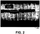
- Figure 2 illustrates an example flash IRT image 200 of a surface of a railcar axle of a railcar wheelset.
- the flash IRT image 200 shows a crack on a surface of the railcar axle.
- the flash IRT image 200 was captured by an infrared camera at a distance of 20 inches from the surface of the railcar axle.
- the brightest areas in the flash IRT image 200 are indicative of the hottest spots on the surface of the railcar axles. Due to the anomalous cooling behavior described above, along the length of the crack, the temperature is not as hot as the hottest spots on the surface of the railcar axle.
- multiple flash IRT units can be positioned along a track, with each flash IRT unit including a flash source and an infrared camera.
- the flash IRT units can be positioned at respective positions and configured to capture infrared data indicative of a surface of a respective sector of a railcar axle of a railcar wheelset.
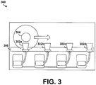
- FIG 3 illustrates an example arrangement 300 of a plurality of flash IRT units 302a-d.
- Each flash IRT unit of the plurality of flash IRT units 302a-d can include a flash source, such as flash source 106 of Figure 1 , and an infrared camera, such as infrared camera 108 of Figure 1 .
- Each flash IRT unit of the plurality of flash IRT units 302a-d is configured to inspect a respective quarter (in other words, a ninety-degree sector) of a surface of a railcar axle 304 of a railcar wheelset sequentially as the railcar wheelset rolls by on a track 306.
- a first flash IRT unit 302a can be configured to capture infrared data indicative of a surface of a first sector of railcar axle 304
- a second flash IRT unit 302b can be configured to capture infrared data indicative of a surface of a second sector of railcar axle 304 after first flash IRT unit 302a captures the infrared data indicative of the surface of the first sector of railcar axle 304 and railcar axle 304 rotates.
- each flash IRT unit 302a-d can be configured to capture infrared data indicative of a surface of a respective sector of railcar axle 304, while the railcar wheelset is rolling on the track.
- each flash IRT unit 302a-d can include a respective trigger sensor, such as trigger sensor 110 of Figure 1 , that triggers the flash IRT unit to inspect railcar axle 304 based on a position of the railcar wheelset on track 306.
- infrared data captured by the plurality of flash IRT units 302a-d can be processed individually and/or in combination.
- a processor such as processor 112 of Figure 1
- the processor could create a composite image of the surfaces of two or more sectors of railcar axle 304, and then process the composite image to determine whether the composite image is indicative of a crack on the surfaces of the two or more sectors of railcar axle 304.
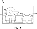
- FIG 4 illustrates another example arrangement 400 of a plurality of flash IRT units 402a-d.
- each flash IRT unit of the plurality of flash IRT units 402a-d can include a flash source and an infrared camera, and be configured to inspect a respective quarter (in other words, a ninety-degree sector) of a surface of a railcar axle 404 of a railcar wheelset, while the railcar wheelset is rolling on a track 406.
- a respective quarter in other words, a ninety-degree sector
- one half of the surface of railcar axle 404 can be inspected a time.
- a first flash IRT unit 402a is configured to capture infrared data indicative of a surface of a first sector of railcar axle 404
- a second flash IRT unit 402b is configured to capture infrared data indicative of a surface of a second sector of railcar axle 404
- first flash IRT unit 402a captures the infrared data indicative of the surface of the first sector or railcar axle 404.
- arrangement 300 over arrangement 400 is that the infrared cameras of the plurality of flash IRT units 302a-d can be placed closer to the surface of railcar axle 304, leading to better spatial resolution.
- one advantage of arrangement 400 over arrangement 300 is that a pair of flash IRT units, such as first flash IRT unit 402a and second flash IRT unit 402b can share a same flash source capacitor bank for charging and discharging.
- Another advantage of arrangement 400 over arrangement 300 is that a pair of flash IRT units can also share a trigger sensor.
- a flash source and an infrared camera of a flash IRT unit can be provided within a protective chamber.
- Figure 5 illustrates an example system having multiple protective chambers 500a-c. As shown in Figure 5 , each protective chamber of the multiple protective chambers 500a-c is arranged beneath a track 502 on which a railcar wheelset 504 rolls, and each protective chamber encapsulates at least one flash source 506 and at least one infrared camera 508.
- FIG 6 illustrates a detailed view of protective chamber 500b of Figure 5 .
- protective chamber 500b includes an infrared transparent window 602 through which flash sources 506 are configured to apply a thermal pulse and infrared camera 508 is configured to capture infrared data.
- protective chamber 500b includes a protective film 604 configured to cover an exterior surface of infrared transparent window 602, and a pair of adjustable rollers 606 configured to adjust which segment of protective film 604 covers the exterior surface of infrared transparent window 602.
- protective film 604 could be a cellophane film.
- the pair of adjustable rollers 606 could be configured to periodically adjust which segment of protective film 604 covers the exterior surface of infrared transparent window 602. For instance, a processor could cause two electric motors to rotate the pair of adjustable rollers 606 clockwise by a predetermined amount, such that an old segment having debris is moved off of the exterior surface of infrared transparent window 602 and a new segment of protective film 604 that is free of debris covers the exterior surface of infrared transparent window 602.
- protective chamber 500b can encapsulate other components as well, such as a vision camera 620 and a communication module (not shown).
- the communication module could be configured to receive instructions for controlling any components within the protective chamber and/or the pair of adjustable rollers 606. Further, the communication module could be configured to send captured infrared data or visual images to a computing device.
- the temperature and humidity within protective chamber 500b can be regulated by a heating and air conditioning system 622.
- Figures 7A-7D illustrate example infrared images 700a-d and visual images 702a-d of a railcar axle 704 that can be displayed on a display screen 706.
- Display screen 706 could be a display of any type of computing device, such as a mobile device, laptop computer, desktop computer, or wearable computer. Alternatively, display screen 706 could be a television.
- the infrared images 700a-d can be captured using infrared cameras 708a-d and flash sources 712a-d, and the visual images can be captured using vision cameras 710a-d.
- Infrared cameras 708a-d can be similar to infrared camera 108 of Figure 1 .
- Flash sources 712a-d can be similar to flash source 106 of Figure 1 .
- Vision cameras 710a-d can be similar to vision camera 120 of Figure 1 .
- a first infrared image 700a and a first visual image 702a of a surface of a first sector of railcar axle 704 can be displayed on display screen 706.
- Display screen 706 can also display an identifier of a railcar and an identifier of the railcar axle 704.
- First infrared image 700a and first visual image 702a do not include any indications of defects, such as a crack, on the surface of the first sector.
- a second infrared image 700b and a second visual image 702b of the surface of a second sector of railcar axle 704 can be displayed on display screen 706, in addition to first infrared image 700a and first visual image 702a.
- Second infrared image 700b and second visual image 702b also do not include any indications of defects, such as a crack, on the surface of the second sector.
- a third infrared image 700c and a third visual image 702c of the surface of a third sector of railcar axle 704 can be displayed on display screen 706, in addition to first infrared image 700a, second infrared image 700b, first visual image 702a, and second visual image 702b.
- Third infrared image 700c and third visual image 702c both include indications of a possible crack on the surface of the third sector of railcar axle 704.
- Viewing the third infrared image 700c and the third visual image 702c may allow an operator to confirm, by comparing third visual image 702c with third infrared image 700c, that an indication in the third infrared image 700c could be a crack.
- a fourth infrared image 700d and a fourth visual image 702d of the surface of a fourth sector of railcar axle 704 can be displayed on display screen 706, in addition to first infrared image 700a, second infrared image 700b, third infrared image 700c, first visual image 702a, second visual image 702b, and third visual image 702c.
- Fourth infrared image 700d and fourth visual image 702d both include indications of a possible crack on the surface of the fourth sector of railcar axle 704.
- third infrared image 700c and fourth infrared image 700d adjacent to one another, an operator can observe and determine that a possible crack spans the surfaces of the third sector and the fourth sector of railcar axle 704, thereby reinforcing the possibility that the indication in third infrared image 700c is a crack and also reinforcing the possibility that the indication in fourth infrared image 700d is also a crack.
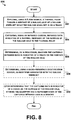
- Figure 8 is a flowchart of an example method 800 for inspecting railcar axles.
- Method 800 shown in Figure 8 presents an embodiment of a method that, for example, could be used with the system shown in Figure 1 , for example, or any of the systems disclosed herein.
- Example devices or systems may be used or configured to perform logical functions presented in Figure 8 .
- Method 800 may include one or more operations, functions, or actions as illustrated by one or more of blocks 802-810. Although these blocks are illustrated in a sequential order, these blocks may also be performed in parallel, and/or in a different order than those described herein. Also, the various blocks may be combined into fewer blocks, divided into additional blocks, and/or removed based upon the desired implementation.
- the method 800 includes applying, using a flash source, a thermal pulse toward a surface of a railcar axle of a railcar wheelset, while the railcar wheelset is on a track.
- a flash source such as flash source 106 of Figure 1
- the flash source can be positioned beneath a height at which the railcar axle rotates above the crack.
- the flash source can apply the thermal pulse, while the railcar wheelset is rolling on the track.
- the method 800 includes capturing, using an infrared camera, infrared data indicative of a thermal response of the surface of the railcar axle to the thermal pulse.
- the thermal response could include changes in temperature on the surface of the railcar axle over time.
- an infrared camera such as infrared camera 108 of Figure 1 , could capture one or more images before the thermal pulse is applied and one or more images after the thermal pulse is applied. The captured images could be indicative of the thermal response during a brief window of time, such as a few microseconds or tens of microseconds.
- the method 800 includes determining, by a processor, whether the captured infrared data is indicative of a crack on the surface of the railcar axle.
- a processor such as processor 112 of Figure 1 , could analyze infrared images captured by the infrared camera to search for areas on the surface that are cooler relative to surrounding areas of the surface. For instance, the processor could search for areas that are, for example, a tenth of a degree cooler, one-half of a degree cooler, or one degree cooler than surrounding areas on the surface. Identifying these areas could involve pre-processing the images to enhance the contrast of temperature differentials on the surface.
- the processor could use machine learning techniques to determine whether the captured infrared data is indicative of a crack on the surface of railcar axle. For instance, a machine learning model could be developed using a training set that includes images of thermal responses of surfaces of railcar axles that include cracks. The processor could use the machine learning model to analyze the captured infrared data and assess whether or not the captured infrared data is indicative of a crack on the surface of railcar axle.
- the method 800 includes determining, using an RFID reader, an identifier associated with the railcar wheelset.
- an RFID tag could be attached to the railcar wheelset or attached to a railcar including the railcar wheelset, and an RFID reader, such as RFID reader 116 of Figure 1 , could be configured to identify an identification code stored by the RFID tag.
- the method 800 includes, upon determining that the captured data is indicative of a crack on the surface of the railcar axle, storing the identifier and a representation of the captured infrared data in a memory.
- the representation of the captured infrared data could include the captured infrared data itself, such as one or more infrared images. Additionally or alternatively, the representation of the captured infrared data could include a processed version of the captured infrared data, such as temperature derivatives calculated from a sequence of infrared images. Storing the representation of the captured infrared data in the memory allows an operator to subsequently review the data and, for example, decide whether an inspector should perform a further inspection of the railcar axle for cracks.
- the identifier and/or the representation of the captured infrared data could also be presented to an operator, and then operator could then decide to order replacement parts after reviewing the identifier and/or the representation of the captured infrared data. Additionally or alternatively, after receiving the identifier, the operator could schedule a maintenance operation for the railcar axle.
- the maintenance operation could include an inspection or a removal of the railcar axle (and optionally the railcar wheelset) from service.
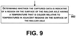
- Figure 9 shows an additional operation for use with the method 800 shown in Figure 8 .
- Block 902 of Figure 9 could be performed as part of the determining whether the captured data is indicative of a crack on the surface of the railcar axle at block 802 of Figure 8 .
- Figure 9 includes determining whether the captured data is indicative of a region on the surface of the railcar axle having a temperature that is colder relative to temperatures in adjacent regions on the surface of the railcar axle.
- a processor such as processor 112 of Figure 1 , could search for a region on the surface of the railcar axle that, in multiple infrared images, has a temperature that is colder relative to temperatures in adjacent regions of the railcar axle.
Landscapes
- Physics & Mathematics (AREA)
- General Physics & Mathematics (AREA)
- Engineering & Computer Science (AREA)
- General Health & Medical Sciences (AREA)
- Health & Medical Sciences (AREA)
- Life Sciences & Earth Sciences (AREA)
- Analytical Chemistry (AREA)
- Biochemistry (AREA)
- Chemical & Material Sciences (AREA)
- Immunology (AREA)
- Pathology (AREA)
- Spectroscopy & Molecular Physics (AREA)
- Mechanical Engineering (AREA)
- Aviation & Aerospace Engineering (AREA)
- Signal Processing (AREA)
- Biomedical Technology (AREA)
- Electromagnetism (AREA)
- Multimedia (AREA)
- Investigating Or Analyzing Materials Using Thermal Means (AREA)
- Investigating Materials By The Use Of Optical Means Adapted For Particular Applications (AREA)
- Radiation Pyrometers (AREA)
Abstract
Description
- The present disclosure relates generally to thermographic inspection, and more particularly, to inspection of railcar axles using flash infrared thermography (IRT).
- Flash IRT is a thermal transient technique that uses a flash source, an infrared camera, and an image processor to analyze a structure. In one approach, one or more short pulses of high thermal energy are applied to a thermally-conductive surface of a structure using a flash source. An infrared camera is then used to monitor and record thermal transients of the surface as heat disperses into the structure and the surface returns to its normal temperature. For instance, an infrared camera can be used to capture images of the surface before and after the pulses are applied.
- Further, the images can then be analyzed using various image processing techniques in order to discriminate between different features and materials. In practice, material imperfections, such as voids, delaminations, or cracks, can affect the cooling of the surface by causing an area of the surface to cool down faster or slower relative to other areas of the surface. Image processing algorithms can analyze a sequence of images and enhance the contrast of relatively warm (or cold) spots on the surface, which may be indicative of material imperfections. Further, image processing algorithms can also be used to assist in the evaluation and/or characterization of any anomalous cooling behavior.
- Railcar axles of railcar wheelsets are important components of modern railcars, and are designed to withstand large amounts of stress. However, over time, railcar axles can sometimes experience failures resulting from axle fatigue. In some cases, a crack can form on the surface of a railcar axle, weakening the strength of the railcar axle. If the crack is undetected, the crack can lead to a failure, such as an axle fracture. Accordingly, there is a need to identify surface cracks on railcar axles, in order to repair or replace them before failures occur.
- Various approaches to detecting surface cracks on railcar axles exist. As one example, ultrasonic inspection can be used to inspect a surface of a railcar axle. As another example, an inspector can apply a liquid dye to a surface of a railcar axle, and observe the penetration of the liquid dye into the surface.
- In one example, a system for inspecting railcar axles is described. The system includes a flash source, an infrared camera, and a trigger sensor. The flash source is configured to apply a thermal pulse toward a surface of a railcar axle of a railcar wheelset, while the railcar wheelset is on a track. The infrared camera is configured to capture infrared data indicative of a thermal response of the surface of the railcar axle to the thermal pulse. The trigger sensor is configured to trigger the flash source to apply the thermal pulse based on a position of the railcar wheelset on the track.
- In another example, a system for inspecting railcar axles is described. The system includes a plurality of flash infrared thermography (IRT) units positioned along a track, and a processor. Each flash IRT unit of the plurality of flash IRT units includes a flash source and an infrared camera. Each flash IRT unit of the plurality of flash IRT units is positioned at a respective position and configured to capture infrared data indicative of a surface of a respective sector of a railcar axle of a railcar wheelset. The processor is configured to determine whether any of the captured infrared data is indicative of a crack on the surface of any sectors of the railcar axle.
- In another example, a method of inspecting railcar axles is described. The method includes applying, using a flash source, a thermal pulse toward a surface of a railcar axle of a railcar wheelset, while the railcar wheelset is on a track. The method also includes capturing, using an infrared camera, infrared data indicative of a thermal response of the surface of the railcar axle to the thermal pulse. Further, the method includes determining, by a processor, whether the captured data is indicative of a crack on the surface of the railcar axle.
- The features, functions, and advantages that have been discussed can be achieved independently in various embodiments or may be combined in yet other embodiments further details of which can be seen with reference to the following description and figures.
- The novel features believed characteristic of the illustrative embodiments are set forth in the appended claims. The illustrative embodiments, however, as well as a preferred mode of use, further objectives and descriptions thereof, will best be understood by reference to the following detailed description of an illustrative embodiment of the present disclosure when read in conjunction with the accompanying figures, wherein:
-
Figure 1 conceptually illustrates an example system, according to an example embodiment. -
Figure 2 illustrates an example flash infrared thermography image of a surface of a railcar axle of a railcar wheelset, according to an example embodiment. -
Figure 3 illustrates an example arrangement of a plurality of flash infrared thermography units, according to an example embodiment. -
Figure 4 illustrates another example arrangement of a plurality of flash infrared thermography units, according to an example embodiment. -
Figure 5 illustrates a system having multiple protective chambers, according to an example embodiment. -
Figure 6 illustrates a detailed view of one of the protective chambers ofFigure 5 . -
Figures 7A-7D illustrate example images that can be displayed on a display screen, according to an example embodiment. -
Figure 8 shows a flowchart of an example method of inspecting railcar axles, according to an example embodiment. -
Figure 9 shows an additional operation for use with the method shown inFigure 8 , according to an example embodiment. - Disclosed embodiments will now be described more fully hereinafter with reference to the accompanying figures, in which some, but not all of the disclosed embodiments are shown. Indeed, several different embodiments may be provided and should not be construed as limited to the embodiments set forth herein. Rather, these embodiments are provided so that this disclosure will be thorough and complete and will fully convey the scope of the disclosure to those skilled in the art.
- Within examples, systems and methods for inspecting railcar axles are described. In some examples, the systems and methods may facilitate inspecting railcar axles for cracks in-situ, in other words, while a railcar wheelset including the railcar axle is on a track. Further, the systems and methods can be used to inspect the railcar axle for cracks, while the wheelset is rolling on the track.
- An example system includes a flash source, an infrared camera, and a trigger sensor. The flash source can be configured to apply a thermal pulse toward a surface of a railcar axle of a railcar wheelset, while the railcar wheelset is on a track. Further, the infrared camera can be configured to capture infrared data indicative of a thermal response of the surface of the railcar axle to the thermal pulse. The flash source and the infrared camera can be positioned beneath a height at which the railcar axle rotates above the track. With this arrangement, the flash source can apply the thermal pulse, and the infrared camera can record the thermal response, from below the railcar axle. The trigger sensor can trigger the flash source to apply the thermal pulse based on a position of the railcar wheelset on the track. For instance, the trigger sensor can include a proximity sensor that can be triggered based on a proximity of a wheel of a railcar wheelset to the proximity sensor.
- The systems described herein can also include one or more processors configured to process infrared data captured by the infrared camera and determine whether the infrared data is indicative of a crack on the surface of the railcar axle. If the surface of the railcar axle includes a crack, the captured infrared data may include data indicative of the presence of the crack. For instance, since a crack is an area where material is missing on the surface, the crack may appear in the captured data as an area that is cooler relative to surrounding areas on the surface. A processor or group of processors can be configured to identify these cooler areas as possible cracks. Cracks on the surface may also be detectable in this manner when dirt or other substances are present on the surface of the railcar axle.
- If a potential crack is identified, the railcar axle, or the railcar wheelset including the railcar axle, can be flagged for further inspection. In one approach, an identifier such as a radio-frequency identifier corresponding to the railcar wheelset can be stored in a memory along with the captured data or a representation of the captured data. Additionally or alternatively, a marking tool can apply a visible marking to the railcar wheelset upon determining that the captured infrared data is indicative of a crack on the surface of the railcar axle.
- In some examples, multiple flash IRT units can be positioned along a track, with each flash IRT unit including a flash source and an infrared camera. The flash IRT units can be positioned at respective positions and configured to capture infrared data indicative of a surface of a respective sector of a railcar axle of a railcar wheelset. For instance, four IRT units could be configured to capture data indicative of four, ninety-degree sectors, respectively, as the railcar wheelset rolls on the track. For each revolution, the railcar axle covers a distance equal to the circumference of the wheels of the railcar wheelset. For example, a wheel having a diameter of one meter moves approximately 3.14 meters per revolution. Accordingly, four IRT units could be arranged within a distance of 3.14 meters in order to capture infrared data indicative of an entire surface of a railcar axle having wheels with a diameter of one meter.
- The systems and methods described herein also have benefits over other inspection systems and methods. Because of the rapid measurement capability, as well as the ability to function without physically contacting the railcar axle, the systems described herein are well-suited for in-motion crack detection for in-situ railcar axles. In addition, the systems described herein can be more cost effective to manufacturer and implement. Using ultrasonic inspection would be more complicated, slower, and less cost-effective, owing to the need to position an ultrasonic array against the surface of a railcar axle and then retract the ultrasonic array away from the railcar axle before the wheelset advances on the track. Similarly, using approaches that include liquid dye penetrants would also be more complicated and slower, due to the time needed to apply the liquid dye to the surface and the complexity of doing so.
- Further, the systems described herein, and associated methods, are different than performing other thermal imaging techniques due to the challenges presented by inspecting a railcar axle while the railcar wheelset is on a track. At, for example, ten miles per hour, a one-meter railcar axle travels a distance of about five meters per second. The challenge is to synchronize operation of a flash source and an infrared camera with this movement of the railcar axle. Triggering the flash source and/or the infrared camera based on a position of the railcar wheelset on the track can help address this challenge. In addition, the flash source and the infrared camera can be mounted beneath a height at which the railcar axle rotates above the track, so that the system can function while the railcar wheelset is on the track and the railcar axle rolls over the system. This allows the system to function without having to remove a railcar wheelset from a track. In addition, multiple infrared flash thermography (IRT) units can be positioned a long a track, in order to capture infrared data indicative of the surface of multiple sectors of a railcar wheelset.
- Various other features of the example systems discussed above, as well as methods for inspecting a surface of a railcar axle using these systems, are also described hereinafter with reference to the accompanying figures.
- Referring now to the figures,
Figure 1 is a conceptual illustration of anexample system 100. In line with the discussion above, thesystem 100 may be used to inspect a surface, such as a surface of arailcar axle 102 of arailcar wheelset 104. As shown inFigure 1 ,system 100 includes aflash source 106, aninfrared camera 108, atrigger sensor 110, aprocessor 112, aspeed sensor 114, anRFID reader 116, a markingtool 118, and avision camera 120. - Flash
source 106 can be configured to apply a thermal pulse toward a surface ofrailcar axle 102 whilerailcar wheelset 104 is on atrack 122. Flashsource 106 can include a housing, a lighting element, and one or more reflectors. In one example,flash source 106 can include or take the form of a flash lamp. Flashsource 106 can be a linear flash source that is arranged parallel to a longitudinal axis ofrailcar axle 102, and perpendicular to track 122. Flashsource 106 can be configured to convert energy stored in a capacitor (not shown), or bank of capacitors, into the thermal pulse. - As shown in
Figure 1 ,flash source 106 can be positioned beneath a height at which therailcar axle 102 rotates abovetrack 122. With this arrangement,flash source 106 can illuminate part of a surface ofrailcar axle 102 from belowrailcar axle 102 whilerailcar axle 102 is ontrack 122. In some examples,flash source 106 can apply the thermal pulse to the surface of one of a plurality of sectors ofrailcar axle 102. Diagram 124 illustrates six example sectors ofrailcar axle 102. The number of sectors could vary depending on the desired implementation. For instance, the number of sectors could instead be three, four, or five. - Further,
flash source 106 can be configured to apply the thermal pulse whilerailcar wheelset 104 is rolling on the track. For instance,flash source 106 can be configured apply the thermal pulse while railcar wheelset is rolling on the track at a speed that is greater than five miles per hour (mph) or at a speed that is greater than ten mph. This can include, for example, a speed between 10 mph and 20 mph. -
Infrared camera 108 can be configured to capture infrared data indicative of a thermal response of the surface ofrailcar axle 102 to the thermal pulse. For instance,infrared camera 108 can be configured to capture one or more images before the thermal pulse is applied and one or more images after the thermal pulse is applied. The images captured byinfrared camera 108 could be indicative of the thermal response during a brief window of time, such as a few microseconds or tens of microseconds. In line with the discussion above, if the surface ofrailcar axle 102 includes a crack, the crack can cause a portion of the surface to be cooler than surrounding areas on the surface.Infrared camera 108 can capture infrared data that reflects this temperature anomaly. - Like
flash source 106,infrared camera 108 can be positioned beneath a height at which therailcar axle 102 rotates abovetrack 122. With this arrangement,flash source 106 can image part of a surface ofrailcar axle 102 from belowrailcar axle 102 whilerailcar axle 102 is ontrack 122. In some examples,infrared camera 108 can image one of a plurality of sectors ofrailcar axle 102. - Further,
infrared camera 108 can be configured to image the surface ofrailcar axle 102, whilerailcar wheelset 104 is rolling on the track. For instance, infrared can be configured image the surface ofrailcar axle 102, while railcar wheelset is rolling on the track at a speed that is greater than five mph or at a speed that is greater than ten mph. This can include, for example, a speed between 10 mph and 20 mph. -
Trigger sensor 110 can be configured to triggerflash source 106 to apply the thermal pulse based on a position ofrailcar wheelset 104 ontrack 122. For instance,trigger sensor 110 can be configured to triggerflash source 106 to apply the thermal pulse upon detection ofrailcar wheelset 104, or upon detection ofrailcar wheelset 104 and expiration of a delay time. In one example,trigger sensor 110 can take the form of or include a proximity sensor. The proximity sensor could be configured to emit an electromagnetic field and look for changes in the electromagnetic field or return signal. The proximity sensor could alternatively include an emitter and a receiver positioned on opposite sides of a track. Whenrailcar wheelset 104 passes between the emitter and the receiver, the proximity sensor could detect the presence ofrailcar wheelset 104. - In some examples,
trigger sensor 110 can triggerflash source 106 to apply the thermal pulse by providing a trigger signal directly toflash source 106. Alternatively,trigger sensor 110 can triggerflash source 106 to apply the thermal pulse by providing a trigger signal or instruction toprocessor 112, which causesprocessor 112 to causeflash source 106 to apply the thermal pulse. - In one example,
trigger sensor 110 can also be configured to triggerinfrared camera 108 to capture the infrared data based on a position ofrailcar wheelset 104 ontrack 122. For instance,trigger sensor 110 can be configured to triggerinfrared camera 108 to capture the infrared data upon detection ofrailcar wheelset 104, or upon detection ofrailcar wheelset 104 and expiration of a delay time.Trigger sensor 110 can triggerinfrared camera 108 to capture the infrared data by providing a trigger signal directly toinfrared camera 108. Alternatively,trigger sensor 110 can triggerinfrared camera 108 to capture the infrared data by providing a trigger signal toprocessor 112, which causesprocessor 112 to causeinfrared camera 108 to capture the infrared data. -
Speed sensor 114 can be configured to determine a speed ofrailcar wheelset 104.Speed sensor 114 could include a laser rangefinder, for example. -
RFID reader 116 can be configured to determine an identifier associated withrailcar wheelset 104. For instance, anRFID tag 126 could be attached torailcar wheelset 104 or attached to a railcar includingrailcar wheelset 104, andRFID reader 116 could be configured to identify an identification code stored byRFID tag 126. - Marking
tool 118 can be configured to apply a visible marking torailcar wheelset 104. For instance, marking tool can be configured to spray a visible marking onto a portion ofrailcar wheelset 104. -
Vision camera 120 can be configured to capture visual images of the surface ofrailcar axle 102. The visual images of the surface ofrailcar axle 102 can be stored in a memory for subsequent review by an inspector ifprocessor 112 determines that the captured infrared data is indicative of a crack on the surface ofrailcar axle 102. - In some examples, visual images of the surface of the
railcar axle 102 can be overlaid with or shown adjacent to infrared images captured byinfrared camera 108 to assist an operator in determination of damage. By way of example, a first infrared image of the surface of a first sector of therailcar axle 102 can be displayed in conjunction with (e.g., at the same time as) a first visual image of the surface of the first sector of therailcar axle 102, and a second visual image of the surface of a second sector of therailcar axle 102 can be displayed in conjunction with a second visual image of the surface of the second sector of therailcar axle 102. This may allow an operator to observe a crack spanning between the surface of the first sector and the surface of the sector. Visual images and corresponding infrared images of the surface of individual sectors can be displayed individually. Alternatively, visual images and corresponding infrared images of the surface of multiple sectors can be displayed at the same time. Displaying visual images of the surface of therailcar axle 102 overlaid with or adjacent to infrared images of the surface of therailcar axle 102 can improve the ability of an operator to discriminate between cracks and non-cracks on the surface of therailcar axle 102. For instance, displaying visual images and infrared images together can lessen the number of false positives and/or false negatives. -
Vision camera 120 can include one or more light emitting diodes (LEDs) configured to illuminate the surface ofrailcar axle 102. In one example,vision camera 120 can include a blue LED configured to illuminate the surface ofrailcar axle 102. Illuminating the surface ofrailcar axle 102 using a blue LED is advantageous because some contaminants, such as oil and grease, fluoresce when illuminated near ultraviolet wavelengths. Hence, by illuminating the surface using blue light (e.g., light having a wavelength between about 380 nanometers and 500 nanometers), contaminants on the surface may be reflected in data captured byvision camera 120, allowing an operator to more easily discriminate between cracks and surface contamination. -
Processor 112 may be any type of processor, such as a microprocessor, digital signal processor, multicore processor, etc.Processor 112 can be configured to determine whether the captured infrared data is indicative of a crack on the surface ofrailcar axle 102. To make this determination,processor 112 could receive one or more images frominfrared camera 108, and analyze the images to look for areas on the surface that are cooler relative to surrounding areas of the surface. For instance,processor 112 could be configured to look for areas that are, for example, a tenth of a degree cooler, one-half of a degree cooler, or one degree cooler than surrounding areas on the surface. Another technique for identifying colder areas is calculating thermal gradients and searching for areas having non-zero thermal gradients. Identifying colder areas could involve pre-processing the images to enhance the contrast of temperature differentials on the surface. - In some examples,
processor 112 could use machine learning techniques to determine whether the captured infrared data is indicative of a crack on the surface ofrailcar axle 102. For instance, a machine learning model could be developed using a training set that includes images of thermal responses of surfaces of railcar axles that include cracks.Processor 112 could use the machine learning model to analyze the captured infrared data and assess whether or not the captured infrared data is indicative of a crack on the surface ofrailcar axle 102. - As noted above, in addition to or instead of the crack detection functions,
processor 112 could be configured to perform synchronization functions. For example,processor 112 could be configured to receive a trigger signal fromtrigger sensor 110, and based on receiving the trigger signal, to causeflash source 106 to apply the thermal pulse and/or to causeinfrared camera 108 to capture the infrared data. In one example,processor 112 could receive data fromspeed sensor 114 indicative of a speed ofrailcar wheelset 104, and determine when to triggerflash source 106 and/orinfrared camera 108 using the speed ofrailcar wheelset 104. - In some examples, upon determining that the captured infrared data is indicative of a crack on the surface of
railcar axle 102,processor 112 can store an identifier associated withrailcar wheelset 104 in a memory. For example,processor 112 can determine an identifier usingRFID reader 116, and store the identifier in the memory. Additionally or alternatively, upon determining that the captured infrared data is indicative of a crack on the surface ofrailcar axle 102,processor 112 can causemarking tool 118 to apply a visible marking torailcar wheelset 104. To facilitate the marking,processor 112 could receive data fromspeed sensor 114 indicative of a speed ofrailcar wheelset 104, and determine when to causemarking tool 118 to apply the visible marking using the speed ofrailcar wheelset 104. -
Processor 112 could be configured to carry out any of the processor functions described herein by executing program instructions stored in a non-transitory computer-readable medium. Further,processor 112 could be part of a computing device that is connected to a network via a wired or wireless connection. In this manner, the computing device can relay the captured infrared data, the identifier of therailcar wheelset 104, and/or the visual images to another computing device. - Flash
source 106,infrared camera 108,trigger sensor 110,speed sensor 114,RFID reader 116, markingtool 118, andvision camera 120 can be communicatively coupled toprocessor 112 via one or more wired orwireless links 128. -
Figure 2 illustrates an exampleflash IRT image 200 of a surface of a railcar axle of a railcar wheelset. Theflash IRT image 200 shows a crack on a surface of the railcar axle. Theflash IRT image 200 was captured by an infrared camera at a distance of 20 inches from the surface of the railcar axle. The brightest areas in theflash IRT image 200 are indicative of the hottest spots on the surface of the railcar axles. Due to the anomalous cooling behavior described above, along the length of the crack, the temperature is not as hot as the hottest spots on the surface of the railcar axle. - In line with the discussion above, in some examples, multiple flash IRT units can be positioned along a track, with each flash IRT unit including a flash source and an infrared camera. The flash IRT units can be positioned at respective positions and configured to capture infrared data indicative of a surface of a respective sector of a railcar axle of a railcar wheelset.
- By way of example,
Figure 3 illustrates anexample arrangement 300 of a plurality offlash IRT units 302a-d. Each flash IRT unit of the plurality offlash IRT units 302a-d can include a flash source, such asflash source 106 ofFigure 1 , and an infrared camera, such asinfrared camera 108 ofFigure 1 . Each flash IRT unit of the plurality offlash IRT units 302a-d is configured to inspect a respective quarter (in other words, a ninety-degree sector) of a surface of arailcar axle 304 of a railcar wheelset sequentially as the railcar wheelset rolls by on atrack 306. For instance, a firstflash IRT unit 302a can be configured to capture infrared data indicative of a surface of a first sector ofrailcar axle 304, and a secondflash IRT unit 302b can be configured to capture infrared data indicative of a surface of a second sector ofrailcar axle 304 after firstflash IRT unit 302a captures the infrared data indicative of the surface of the first sector ofrailcar axle 304 andrailcar axle 304 rotates. - Further, each
flash IRT unit 302a-d can be configured to capture infrared data indicative of a surface of a respective sector ofrailcar axle 304, while the railcar wheelset is rolling on the track. According to one approach, eachflash IRT unit 302a-d can include a respective trigger sensor, such astrigger sensor 110 ofFigure 1 , that triggers the flash IRT unit to inspectrailcar axle 304 based on a position of the railcar wheelset ontrack 306. - In addition, infrared data captured by the plurality of
flash IRT units 302a-d can be processed individually and/or in combination. For instance, a processor, such asprocessor 112 ofFigure 1 , can be configured to process the infrared data captured by firstflash IRT unit 302a to determine whether the captured infrared data is indicative of a crack on the surface of the first sector ofrailcar axle 304, and then process infrared data captured by secondflash IRT unit 302b to determine whether the captured infrared data is indicative of a crack on the surface of the second sector ofrailcar axle 304, and so forth. Additionally or alternatively, the processor could create a composite image of the surfaces of two or more sectors ofrailcar axle 304, and then process the composite image to determine whether the composite image is indicative of a crack on the surfaces of the two or more sectors ofrailcar axle 304. -
Figure 4 illustrates anotherexample arrangement 400 of a plurality offlash IRT units 402a-d. Likearrangement 300 ofFigure 3 , each flash IRT unit of the plurality offlash IRT units 402a-d can include a flash source and an infrared camera, and be configured to inspect a respective quarter (in other words, a ninety-degree sector) of a surface of arailcar axle 404 of a railcar wheelset, while the railcar wheelset is rolling on atrack 406. Unlikearrangement 300 ofFigure 3 , however, inarrangement 400, one half of the surface ofrailcar axle 404 can be inspected a time. For instance, a firstflash IRT unit 402a is configured to capture infrared data indicative of a surface of a first sector ofrailcar axle 404, and a secondflash IRT unit 402b is configured to capture infrared data indicative of a surface of a second sector ofrailcar axle 404, while firstflash IRT unit 402a captures the infrared data indicative of the surface of the first sector orrailcar axle 404. - One advantage of
arrangement 300 overarrangement 400 is that the infrared cameras of the plurality offlash IRT units 302a-d can be placed closer to the surface ofrailcar axle 304, leading to better spatial resolution. On the other hand, one advantage ofarrangement 400 overarrangement 300 is that a pair of flash IRT units, such as firstflash IRT unit 402a and secondflash IRT unit 402b can share a same flash source capacitor bank for charging and discharging. Another advantage ofarrangement 400 overarrangement 300 is that a pair of flash IRT units can also share a trigger sensor. - Dirt, mud, grease, and other debris could impact the quality of infrared data captured by a flash IRT unit, such as any of the plurality of
flash IRT units 302a-d ofFigure 3 or the plurality offlash IRT units 402a-d ofFigure 4 . To address this issue, in some embodiments, a flash source and an infrared camera of a flash IRT unit can be provided within a protective chamber.Figure 5 illustrates an example system having multipleprotective chambers 500a-c. As shown inFigure 5 , each protective chamber of the multipleprotective chambers 500a-c is arranged beneath atrack 502 on which arailcar wheelset 504 rolls, and each protective chamber encapsulates at least oneflash source 506 and at least oneinfrared camera 508. -
Figure 6 illustrates a detailed view ofprotective chamber 500b ofFigure 5 . As shown inFigure 6 ,protective chamber 500b includes an infraredtransparent window 602 through whichflash sources 506 are configured to apply a thermal pulse andinfrared camera 508 is configured to capture infrared data. Further,protective chamber 500b includes aprotective film 604 configured to cover an exterior surface of infraredtransparent window 602, and a pair ofadjustable rollers 606 configured to adjust which segment ofprotective film 604 covers the exterior surface of infraredtransparent window 602. - In one example,
protective film 604 could be a cellophane film. Further, the pair ofadjustable rollers 606 could be configured to periodically adjust which segment ofprotective film 604 covers the exterior surface of infraredtransparent window 602. For instance, a processor could cause two electric motors to rotate the pair ofadjustable rollers 606 clockwise by a predetermined amount, such that an old segment having debris is moved off of the exterior surface of infraredtransparent window 602 and a new segment ofprotective film 604 that is free of debris covers the exterior surface of infraredtransparent window 602. - In some examples,
protective chamber 500b can encapsulate other components as well, such as avision camera 620 and a communication module (not shown). The communication module could be configured to receive instructions for controlling any components within the protective chamber and/or the pair ofadjustable rollers 606. Further, the communication module could be configured to send captured infrared data or visual images to a computing device. In some examples, the temperature and humidity withinprotective chamber 500b can be regulated by a heating andair conditioning system 622. -
Figures 7A-7D illustrate exampleinfrared images 700a-d andvisual images 702a-d of arailcar axle 704 that can be displayed on adisplay screen 706.Display screen 706 could be a display of any type of computing device, such as a mobile device, laptop computer, desktop computer, or wearable computer. Alternatively,display screen 706 could be a television. Theinfrared images 700a-d can be captured usinginfrared cameras 708a-d andflash sources 712a-d, and the visual images can be captured usingvision cameras 710a-d.Infrared cameras 708a-d can be similar toinfrared camera 108 ofFigure 1 .Flash sources 712a-d can be similar toflash source 106 ofFigure 1 .Vision cameras 710a-d can be similar tovision camera 120 ofFigure 1 . - As shown in
Figure 7A , at a first time period, a firstinfrared image 700a and a firstvisual image 702a of a surface of a first sector ofrailcar axle 704 can be displayed ondisplay screen 706.Display screen 706 can also display an identifier of a railcar and an identifier of therailcar axle 704. Firstinfrared image 700a and firstvisual image 702a do not include any indications of defects, such as a crack, on the surface of the first sector. - As shown in
Figure 7B , at a second time period, a secondinfrared image 700b and a secondvisual image 702b of the surface of a second sector ofrailcar axle 704 can be displayed ondisplay screen 706, in addition to firstinfrared image 700a and firstvisual image 702a. Secondinfrared image 700b and secondvisual image 702b also do not include any indications of defects, such as a crack, on the surface of the second sector. - As shown in
Figure 7C , at a third time period, a thirdinfrared image 700c and a thirdvisual image 702c of the surface of a third sector ofrailcar axle 704 can be displayed ondisplay screen 706, in addition to firstinfrared image 700a, secondinfrared image 700b, firstvisual image 702a, and secondvisual image 702b. Thirdinfrared image 700c and thirdvisual image 702c both include indications of a possible crack on the surface of the third sector ofrailcar axle 704. Viewing the thirdinfrared image 700c and the thirdvisual image 702c may allow an operator to confirm, by comparing thirdvisual image 702c with thirdinfrared image 700c, that an indication in the thirdinfrared image 700c could be a crack. - As shown in
Figure 7D , at a fourth time period, a fourthinfrared image 700d and a fourthvisual image 702d of the surface of a fourth sector ofrailcar axle 704 can be displayed ondisplay screen 706, in addition to firstinfrared image 700a, secondinfrared image 700b, thirdinfrared image 700c, firstvisual image 702a, secondvisual image 702b, and thirdvisual image 702c. Fourthinfrared image 700d and fourthvisual image 702d both include indications of a possible crack on the surface of the fourth sector ofrailcar axle 704. By viewing thirdinfrared image 700c and fourthinfrared image 700d adjacent to one another, an operator can observe and determine that a possible crack spans the surfaces of the third sector and the fourth sector ofrailcar axle 704, thereby reinforcing the possibility that the indication in thirdinfrared image 700c is a crack and also reinforcing the possibility that the indication in fourthinfrared image 700d is also a crack. -
Figure 8 is a flowchart of anexample method 800 for inspecting railcar axles.Method 800 shown inFigure 8 presents an embodiment of a method that, for example, could be used with the system shown inFigure 1 , for example, or any of the systems disclosed herein. Example devices or systems may be used or configured to perform logical functions presented inFigure 8 .Method 800 may include one or more operations, functions, or actions as illustrated by one or more of blocks 802-810. Although these blocks are illustrated in a sequential order, these blocks may also be performed in parallel, and/or in a different order than those described herein. Also, the various blocks may be combined into fewer blocks, divided into additional blocks, and/or removed based upon the desired implementation. - Initially, at
block 802, themethod 800 includes applying, using a flash source, a thermal pulse toward a surface of a railcar axle of a railcar wheelset, while the railcar wheelset is on a track. By way of example, a flash source, such asflash source 106 ofFigure 1 , can convert energy stored in a capacitor or bank of capacitors into the thermal pulse. The flash source can be positioned beneath a height at which the railcar axle rotates above the crack. The flash source can apply the thermal pulse, while the railcar wheelset is rolling on the track. - At
block 804, themethod 800 includes capturing, using an infrared camera, infrared data indicative of a thermal response of the surface of the railcar axle to the thermal pulse. The thermal response could include changes in temperature on the surface of the railcar axle over time. In one example, an infrared camera, such asinfrared camera 108 ofFigure 1 , could capture one or more images before the thermal pulse is applied and one or more images after the thermal pulse is applied. The captured images could be indicative of the thermal response during a brief window of time, such as a few microseconds or tens of microseconds. - At
block 806, themethod 800 includes determining, by a processor, whether the captured infrared data is indicative of a crack on the surface of the railcar axle. In one example, a processor, such asprocessor 112 ofFigure 1 , could analyze infrared images captured by the infrared camera to search for areas on the surface that are cooler relative to surrounding areas of the surface. For instance, the processor could search for areas that are, for example, a tenth of a degree cooler, one-half of a degree cooler, or one degree cooler than surrounding areas on the surface. Identifying these areas could involve pre-processing the images to enhance the contrast of temperature differentials on the surface. In another example, the processor could use machine learning techniques to determine whether the captured infrared data is indicative of a crack on the surface of railcar axle. For instance, a machine learning model could be developed using a training set that includes images of thermal responses of surfaces of railcar axles that include cracks. The processor could use the machine learning model to analyze the captured infrared data and assess whether or not the captured infrared data is indicative of a crack on the surface of railcar axle. - Optionally, at
block 808, themethod 800 includes determining, using an RFID reader, an identifier associated with the railcar wheelset. For instance, an RFID tag could be attached to the railcar wheelset or attached to a railcar including the railcar wheelset, and an RFID reader, such asRFID reader 116 ofFigure 1 , could be configured to identify an identification code stored by the RFID tag. - Optionally, at
block 810, themethod 800 includes, upon determining that the captured data is indicative of a crack on the surface of the railcar axle, storing the identifier and a representation of the captured infrared data in a memory. The representation of the captured infrared data could include the captured infrared data itself, such as one or more infrared images. Additionally or alternatively, the representation of the captured infrared data could include a processed version of the captured infrared data, such as temperature derivatives calculated from a sequence of infrared images. Storing the representation of the captured infrared data in the memory allows an operator to subsequently review the data and, for example, decide whether an inspector should perform a further inspection of the railcar axle for cracks. - The identifier and/or the representation of the captured infrared data could also be presented to an operator, and then operator could then decide to order replacement parts after reviewing the identifier and/or the representation of the captured infrared data. Additionally or alternatively, after receiving the identifier, the operator could schedule a maintenance operation for the railcar axle. The maintenance operation could include an inspection or a removal of the railcar axle (and optionally the railcar wheelset) from service.
-
Figure 9 shows an additional operation for use with themethod 800 shown inFigure 8 .Block 902 ofFigure 9 could be performed as part of the determining whether the captured data is indicative of a crack on the surface of the railcar axle atblock 802 ofFigure 8 . Atblock 902,Figure 9 includes determining whether the captured data is indicative of a region on the surface of the railcar axle having a temperature that is colder relative to temperatures in adjacent regions on the surface of the railcar axle. In one example, a processor, such asprocessor 112 ofFigure 1 , could search for a region on the surface of the railcar axle that, in multiple infrared images, has a temperature that is colder relative to temperatures in adjacent regions of the railcar axle. - Further, the disclosure comprises embodiments according to the following clauses:
-
Clause 1. A system for inspecting railcar axles, comprising:- a flash source configured to apply a thermal pulse toward a surface of a railcar axle of a railcar wheelset while the railcar wheelset is on a track;
- an infrared camera configured to capture infrared data indicative of a thermal response of the surface of the railcar axle to the thermal pulse; and
- a trigger sensor configured to trigger the flash source to apply the thermal pulse based on a position of the railcar wheelset on the track.
-
Clause 2. The system ofclause 1, wherein the trigger sensor is further configured to trigger the infrared camera to capture the infrared data based on the position of the railcar wheelset on the track. -
Clause 3. The system of any one of clauses 1-2, further comprising a processor configured to determine whether the captured infrared data is indicative of a crack on the surface of the railcar axle. -
Clause 4. The system ofclause 3, further comprising a marking tool, wherein the processor is configured to cause the marking tool to apply a visible marking to the railcar wheelset upon determining that the captured infrared data is indicative of a crack on the surface of the railcar axle. -
Clause 5. The system of any one of clauses 3-4, further comprising a radio-frequency identification reader configured to determine an identifier associated with the railcar wheelset, wherein the processor is configured to store the identifier in a memory upon determining that the captured infrared data is indicative of a crack on the surface of the railcar axle. -
Clause 6. The system of any one of clauses 1-5, wherein the flash source and the infrared camera are positioned beneath a height at which the railcar axle rotates above the track. - Clause 7. The system of any one of clauses 1-6, wherein the flash source is configured to apply the thermal pulse while the railcar wheelset is rolling on the track, and wherein the infrared camera is configured to capture the infrared data while the railcar wheelset is rolling on the track.
- Clause 8. The system of clause 7, wherein the flash source is configured to apply the thermal pulse while the railcar wheelset is rolling on the track, and wherein the infrared camera is configured to capture the infrared data while the railcar wheelset is rolling on the track at a speed of greater than five miles per hour.
- Clause 9. The system of any one of clauses 1-8, wherein the trigger sensor comprises a proximity sensor.
- Clause 10. The system of any one of clauses 1-9, further comprising a protective chamber that encapsulates the flash source and the infrared camera, wherein the protective chamber comprises an infrared transparent window through which the flash source is configured to apply the thermal pulse and the infrared camera is configured to capture the infrared data.
- Clause 11. The system of clause 10, wherein the protective chamber further comprises:
- a protective film configured to cover an exterior surface of the infrared transparent window; and
- a pair of adjustable rollers configured to adjust which segment of the protective film covers the exterior surface of the infrared transparent window.
- Clause 12. The system of any one of clauses 1-11, further comprising a vision camera configured to capture an image of the surface of the railcar axle and store the image of the surface of the railcar axle in a memory.
- Clause 13. A system for inspecting railcar axles, comprising:
- a plurality of flash infrared thermography (IRT) units positioned along a track, each flash IRT unit of the plurality of flash IRT units comprising a flash source and an infrared camera, wherein each flash IRT unit of the plurality of flash IRT units is positioned at a respective position and configured to capture infrared data indicative of a surface of a respective sector of a railcar axle of a railcar wheelset; and
- a processor configured to determine whether any of the captured infrared data is indicative of a crack on the surface of any sectors of the railcar axle.
- Clause 14. The system of clause 13, wherein the plurality of flash IRT units comprise:
- a first flash IRT unit configured to capture infrared data indicative of a surface of a first sector of the railcar axle; and
- a second flash IRT unit configured to capture infrared data indicative of a surface of a second sector of the railcar axle after the first flash IRT unit captures the infrared data indicative of the surface of the first sector of the railcar axle and the railcar axle rotates.
- Clause 15. The system of any one of clauses 13-14, wherein the plurality of flash IRT units comprise:
- a first flash IRT unit configured to capture infrared data indicative of a surface of a first sector of the railcar axle; and
- a second flash IRT unit configured to capture infrared data indicative of a surface of a second sector of the railcar axle while the first flash IRT unit captures the infrared data indicative of the surface of the first sector of the railcar axle.
- Clause 16. The system of any one of clauses 13-15, further comprising at least one trigger sensor configured to trigger the plurality of flash IRT units to capture the infrared data indicative of surfaces of the sectors of the railcar axle based on a position of the railcar wheelset on the track.
- Clause 17. The system of any one of clauses 13-16, wherein each flash IRT unit of the plurality of flash IRT units is configured to capture infrared data indicative of a surface of a respective sector of the railcar axle while the railcar wheelset is rolling on the track.
- Clause 18. A method of inspecting railcar axles, comprising:
- applying, using a flash source, a thermal pulse toward a surface of a railcar axle of a railcar wheelset while the railcar wheelset is on a track;
- capturing, using an infrared camera, infrared data indicative of a thermal response of the surface of the railcar axle to the thermal pulse; and
- determining, by a processor, whether the captured infrared data is indicative of a crack on the surface of the railcar axle.
- Clause 19. The method of clause 18, further comprising:
- determining, using a radio-frequency identification reader, an identifier associated with the railcar wheelset; and
- upon determining that the captured infrared data is indicative of a crack on the surface of the railcar axle, storing the identifier and a representation of the captured infrared data in a memory.
- Clause 20. The method of any one of clauses 18-19, wherein the thermal response comprises changes in temperature on the surface of the railcar axle over time, and wherein determining whether the captured infrared data is indicative of a crack on the surface of the railcar axle comprises determining whether the captured infrared data is indicative of a region on the surface of the railcar axle having a temperature that is colder relative to temperatures in adjacent regions on the surface of the railcar axle.
- The description of the different advantageous arrangements has been presented for purposes of illustration and description, and is not intended to be exhaustive or limited to the embodiments in the form disclosed. Many modifications and variations will be apparent to those of ordinary skill in the art. Further, different advantageous embodiments may provide different advantages as compared to other advantageous embodiments. The embodiment or embodiments selected are chosen and described in order to best explain the principles of the embodiments, the practical application, and to enable others of ordinary skill in the art to understand the disclosure for various embodiments with various modifications as are suited to the particular use contemplated.
Claims (15)
- A system (100) for inspecting railcar axles, comprising:a flash source (106) configured to apply a thermal pulse toward a surface of a railcar axle (102) of a railcar wheelset (104) while the railcar wheelset (104) is on a track (122);an infrared camera (108) configured to capture infrared data indicative of a thermal response of the surface of the railcar axle (102) to the thermal pulse; anda trigger sensor (110) configured to trigger the flash source (106) to apply the thermal pulse based on a position of the railcar wheelset (104) on the track (122).
- The system of claim 1, wherein the trigger sensor (110) is further configured to trigger the infrared camera (108) to capture the infrared data based on the position of the railcar wheelset (104) on the track (122).
- The system of any one of claims 1-2, further comprising a processor (112) configured to determine whether the captured infrared data is indicative of a crack on the surface of the railcar axle (102).
- The system of claim 3, further comprising a marking tool (118), wherein the processor (112) is configured to cause the marking tool (118) to apply a visible marking to the railcar wheelset (104) upon determining that the captured infrared data is indicative of a crack on the surface of the railcar axle (102).
- The system of any one of claims 3-4, further comprising a radio-frequency identification reader (116) configured to determine an identifier associated with the railcar wheelset (104), wherein the processor (112) is configured to store the identifier in a memory upon determining that the captured infrared data is indicative of a crack on the surface of the railcar axle (102).
- The system of claims 1-5, wherein the flash source (106) and the infrared camera (108) are positioned beneath a height at which the railcar axle (102) rotates above the track (122).
- The system of any one of claims 1-6, wherein the flash source (106) is configured to apply the thermal pulse while the railcar wheelset (104) is rolling on the track (122), and wherein the infrared camera (108) is configured to capture the infrared data while the railcar wheelset (104) is rolling on the track (122).
- The system of claim 7, wherein the flash source (106) is configured to apply the thermal pulse while the railcar wheelset (104) is rolling on the track (122), and wherein the infrared camera (108) is configured to capture the infrared data while the railcar wheelset (104) is rolling on the track (122) at a speed of greater than five miles per hour.
- The system of any one of claims 1-8, wherein the trigger sensor (110) comprises a proximity sensor.
- The system of any one of claims 1-9, further comprising a protective chamber (500b) that encapsulates the flash source (106) and the infrared camera (108), wherein the protective chamber (500b) comprises an infrared transparent window (602) through which the flash source (106) is configured to apply the thermal pulse and the infrared camera (108) is configured to capture the infrared data.
- The system of claim 10, wherein the protective chamber (500b) further comprises:a protective film (604) configured to cover an exterior surface of the infrared transparent window (602); anda pair of adjustable rollers (606) configured to adjust which segment of the protective film (604) covers the exterior surface of the infrared transparent window (602).
- The system of any one of claims 1-11, further comprising a vision camera (120) configured to capture an image of the surface of the railcar axle (102) and store the image of the surface of the railcar axle (102) in a memory.
- A method (800) of inspecting railcar axles, comprising:applying (802), using a flash source (106), a thermal pulse toward a surface of a railcar axle (102) of a railcar wheelset (104) while the railcar wheelset (104) is on a track (122);capturing (804), using an infrared camera (108), infrared data indicative of a thermal response of the surface of the railcar axle (102) to the thermal pulse; anddetermining (806), by a processor (112), whether the captured infrared data is indicative of a crack on the surface of the railcar axle (102).
- The method of claim 13, further comprising:determining (808), using a radio-frequency identification reader (116), an identifier associated with the railcar wheelset (104); andupon determining that the captured infrared data is indicative of a crack on the surface of the railcar axle (102), storing (810) the identifier and a representation of the captured infrared data in a memory.
- The method of any one of claims 13-14, wherein the thermal response comprises changes in temperature on the surface of the railcar axle (102) over time, and wherein determining whether the captured infrared data is indicative of a crack on the surface of the railcar axle (102) comprises determining (902) whether the captured infrared data is indicative of a region on the surface of the railcar axle (102) having a temperature that is colder relative to temperatures in adjacent regions on the surface of the railcar axle (102).
Applications Claiming Priority (1)
| Application Number | Priority Date | Filing Date | Title |
|---|---|---|---|
| US16/000,777 US10710615B2 (en) | 2018-06-05 | 2018-06-05 | In-motion high-speed non-destructive evaluation for railcar axles |
Publications (3)
| Publication Number | Publication Date |
|---|---|
| EP3578962A2 true EP3578962A2 (en) | 2019-12-11 |
| EP3578962A3 EP3578962A3 (en) | 2020-01-01 |
| EP3578962B1 EP3578962B1 (en) | 2022-08-31 |
Family
ID=66676213
Family Applications (1)
| Application Number | Title | Priority Date | Filing Date |
|---|---|---|---|
| EP19176653.4A Active EP3578962B1 (en) | 2018-06-05 | 2019-05-27 | In-motion high-speed non-destructive evaluation for railcar axles |
Country Status (4)
| Country | Link |
|---|---|
| US (1) | US10710615B2 (en) |
| EP (1) | EP3578962B1 (en) |
| CN (1) | CN110632121A (en) |
| ES (1) | ES2931777T3 (en) |
Cited By (1)
| Publication number | Priority date | Publication date | Assignee | Title |
|---|---|---|---|---|
| EP4530155A1 (en) * | 2023-09-29 | 2025-04-02 | Gestalt Robotics GmbH | Inspection method and inspection system for vehicles |
Families Citing this family (10)
| Publication number | Priority date | Publication date | Assignee | Title |
|---|---|---|---|---|
| US10710615B2 (en) * | 2018-06-05 | 2020-07-14 | The Boeing Company | In-motion high-speed non-destructive evaluation for railcar axles |
| US11091882B2 (en) | 2019-02-14 | 2021-08-17 | Norfolk Southern Corporation | Edge weather abatement using hyperlocal weather and train activity inputs |
| US11386545B2 (en) | 2020-03-31 | 2022-07-12 | The Boeing Company | Surface crack detection |
| US11507779B1 (en) | 2020-07-24 | 2022-11-22 | Norfolk Southern Corporation | Two-stage deep learning framework for detecting the condition of rail car coupler systems |
| US11468551B1 (en) | 2020-07-24 | 2022-10-11 | Norfolk Southern Corporation | Machine-learning framework for detecting defects or conditions of railcar systems |
| EP4024034B1 (en) * | 2021-01-05 | 2025-05-28 | The Boeing Company | Methods and apparatus for measuring fastener concentricity |
| DE102021204088A1 (en) * | 2021-04-23 | 2022-10-27 | Siemens Mobility GmbH | Method for determining the state of motion of a rail vehicle wheel |
| DE102022204607A1 (en) | 2022-05-11 | 2023-07-13 | Deutsches Zentrum für Luft- und Raumfahrt e.V. | Apparatus, monitoring system and method for monitoring a rail vehicle for thermal damage |
| CN115494113B (en) * | 2022-09-02 | 2024-07-05 | 中铁第一勘察设计院集团有限公司 | An adaptive heating method for improving infrared detection effect of train running gear |
| EP4417959B1 (en) * | 2023-02-14 | 2025-05-07 | DTEC GmbH | An underfloor wheelset inspection device and a method for probing railway vehicle wheelsets using the underfloor wheelset inspection device |
Family Cites Families (13)
| Publication number | Priority date | Publication date | Assignee | Title |
|---|---|---|---|---|
| US2906885A (en) | 1955-06-02 | 1959-09-29 | Itt | Apparatus for detecting hot journal boxes |
| US7724925B2 (en) * | 1999-12-02 | 2010-05-25 | Thermal Wave Imaging, Inc. | System for generating thermographic images using thermographic signal reconstruction |
| GB0216486D0 (en) * | 2002-07-16 | 2002-08-21 | Aea Technology Plc | Inspection of railway vehicles |
| EP2347238B1 (en) * | 2008-10-22 | 2018-05-16 | International Electronic Machines Corp. | Thermal imaging-based vehicle analysis |
| EP2547995B1 (en) * | 2010-03-17 | 2017-07-05 | Thermal Wave Imaging Inc. | Thermographic detection of internal passageway blockages |
| EP2375243B1 (en) * | 2010-04-08 | 2023-06-07 | Institut Dr. Foerster Gmbh & Co. Kg | Thermographic testing method and device for carrying out the testing method |
| EP2743688B1 (en) * | 2012-12-17 | 2017-05-03 | Thermosensorik Gmbh | Method and system for the examination of a sample by means of thermography |
| CN105758889A (en) * | 2016-03-30 | 2016-07-13 | 哈尔滨工业大学 | Oil and gas pipeline infrared thermal wave imaging detection system and method |
| US10191014B2 (en) * | 2016-08-23 | 2019-01-29 | The Boeing Company | System and method for nondestructive evaluation of a test object |
| US9752993B1 (en) | 2016-09-14 | 2017-09-05 | The Boeing Company | Nondestructive evaluation of railroad rails, wheels, and axles |
| CN107295233B (en) * | 2017-07-31 | 2020-05-19 | 重庆三朵蜜生物技术有限公司 | A dust-proof camera |
| CN107576666A (en) * | 2017-10-13 | 2018-01-12 | 成都精工华耀机械制造有限公司 | A kind of double light spectrum image-forming rails and fastener method for detecting abnormality |
| US10710615B2 (en) * | 2018-06-05 | 2020-07-14 | The Boeing Company | In-motion high-speed non-destructive evaluation for railcar axles |
-
2018
- 2018-06-05 US US16/000,777 patent/US10710615B2/en active Active
-
2019
- 2019-05-27 ES ES19176653T patent/ES2931777T3/en active Active
- 2019-05-27 EP EP19176653.4A patent/EP3578962B1/en active Active
- 2019-05-31 CN CN201910470746.1A patent/CN110632121A/en active Pending
Cited By (1)
| Publication number | Priority date | Publication date | Assignee | Title |
|---|---|---|---|---|
| EP4530155A1 (en) * | 2023-09-29 | 2025-04-02 | Gestalt Robotics GmbH | Inspection method and inspection system for vehicles |
Also Published As
| Publication number | Publication date |
|---|---|
| EP3578962B1 (en) | 2022-08-31 |
| US10710615B2 (en) | 2020-07-14 |
| US20190367057A1 (en) | 2019-12-05 |
| EP3578962A3 (en) | 2020-01-01 |
| ES2931777T3 (en) | 2023-01-02 |
| CN110632121A (en) | 2019-12-31 |
Similar Documents
| Publication | Publication Date | Title |
|---|---|---|
| US10710615B2 (en) | In-motion high-speed non-destructive evaluation for railcar axles | |
| EP3682189B1 (en) | Optical wheel evaluation | |
| JP6415034B2 (en) | System and method for remote inspection of aircraft structures | |
| CN105115976B (en) | A kind of rail abrasion defect detecting system and method | |
| US5654977A (en) | Method and apparatus for real time defect inspection of metal at elevated temperature | |
| JP6490366B2 (en) | Method and system for non-destructive inspection | |
| JP2018054604A (en) | Non-destructive evaluation of railway rails, wheels and axles | |
| BRPI0614518A2 (en) | elongated bar imaging system | |
| JP6381094B1 (en) | Tire deterioration evaluation system | |
| CN106324037A (en) | System and method for nondestructive examination of bridge concrete structure defects | |
| WO1997007380A2 (en) | Automated system for vehicle condition evaluation | |
| CN204613120U (en) | Based on the freeway tunnel inspection vehicle system of machine vision | |
| CN115266735A (en) | Metal plate surface defect detection system and detection method thereof | |
| Zhong et al. | Visual testing for fiber-reinforced composite materials | |
| GB2546344A (en) | Vehicle underframe examination system | |
| JP2022545552A (en) | Honeycomb body inspection system and method | |
| Mitra et al. | A UAV Payload for Real-time Inspection of Highway Ancillary Structures | |
| US11386545B2 (en) | Surface crack detection | |
| CN101449153A (en) | Device for non-destructive testing of a component by analyzing radiation dissipation | |
| Czajka et al. | Use of hybrid vision methods for the diagnostics of technical processes | |
| JP2023102417A (en) | PHOTOVOLTAIC SYSTEM INSPECTION DEVICE AND INSPECTION METHOD | |
| CN119251997A (en) | A laboratory intelligent inspection method and system based on multiple data sources | |
| Freid et al. | Multispectral machine vision for improved undercarriage inspection of railroad rolling stock | |
| CN117890376A (en) | Online detection method and system for surface damage of hot rolled bar red steel | |
| Burski et al. | Hybrid vision method for vehicle undercarriage diagnostics |
Legal Events
| Date | Code | Title | Description |
|---|---|---|---|
| PUAI | Public reference made under article 153(3) epc to a published international application that has entered the european phase |
Free format text: ORIGINAL CODE: 0009012 |
|
| STAA | Information on the status of an ep patent application or granted ep patent |
Free format text: STATUS: REQUEST FOR EXAMINATION WAS MADE |
|
| PUAL | Search report despatched |
Free format text: ORIGINAL CODE: 0009013 |
|
| 17P | Request for examination filed |
Effective date: 20190527 |
|
| AK | Designated contracting states |
Kind code of ref document: A2 Designated state(s): AL AT BE BG CH CY CZ DE DK EE ES FI FR GB GR HR HU IE IS IT LI LT LU LV MC MK MT NL NO PL PT RO RS SE SI SK SM TR |
|
| AX | Request for extension of the european patent |
Extension state: BA ME |
|
| AK | Designated contracting states |
Kind code of ref document: A3 Designated state(s): AL AT BE BG CH CY CZ DE DK EE ES FI FR GB GR HR HU IE IS IT LI LT LU LV MC MK MT NL NO PL PT RO RS SE SI SK SM TR |
|
| AX | Request for extension of the european patent |
Extension state: BA ME |
|
| RIC1 | Information provided on ipc code assigned before grant |
Ipc: G01N 25/72 20060101AFI20191126BHEP |
|
| GRAP | Despatch of communication of intention to grant a patent |
Free format text: ORIGINAL CODE: EPIDOSNIGR1 |
|
| STAA | Information on the status of an ep patent application or granted ep patent |
Free format text: STATUS: GRANT OF PATENT IS INTENDED |
|
| INTG | Intention to grant announced |
Effective date: 20211027 |
|
| RIN1 | Information on inventor provided before grant (corrected) |
Inventor name: LEA, SCOTT W. Inventor name: VADDI, JYANI Inventor name: HOLMES, TYLER M. Inventor name: SAFAI, MORTEZA Inventor name: GEORGESON, GARY E. |
|
| GRAJ | Information related to disapproval of communication of intention to grant by the applicant or resumption of examination proceedings by the epo deleted |
Free format text: ORIGINAL CODE: EPIDOSDIGR1 |
|
| STAA | Information on the status of an ep patent application or granted ep patent |
Free format text: STATUS: REQUEST FOR EXAMINATION WAS MADE |
|
| GRAP | Despatch of communication of intention to grant a patent |
Free format text: ORIGINAL CODE: EPIDOSNIGR1 |
|
| STAA | Information on the status of an ep patent application or granted ep patent |
Free format text: STATUS: GRANT OF PATENT IS INTENDED |
|
| INTC | Intention to grant announced (deleted) | ||
| INTG | Intention to grant announced |
Effective date: 20220328 |
|
| GRAS | Grant fee paid |
Free format text: ORIGINAL CODE: EPIDOSNIGR3 |
|
| GRAA | (expected) grant |
Free format text: ORIGINAL CODE: 0009210 |
|
| STAA | Information on the status of an ep patent application or granted ep patent |
Free format text: STATUS: THE PATENT HAS BEEN GRANTED |
|
| AK | Designated contracting states |
Kind code of ref document: B1 Designated state(s): AL AT BE BG CH CY CZ DE DK EE ES FI FR GB GR HR HU IE IS IT LI LT LU LV MC MK MT NL NO PL PT RO RS SE SI SK SM TR |
|
| REG | Reference to a national code |
Ref country code: CH Ref legal event code: EP Ref country code: GB Ref legal event code: FG4D |
|
| REG | Reference to a national code |
Ref country code: AT Ref legal event code: REF Ref document number: 1515648 Country of ref document: AT Kind code of ref document: T Effective date: 20220915 Ref country code: DE Ref legal event code: R096 Ref document number: 602019018837 Country of ref document: DE |
|
| REG | Reference to a national code |
Ref country code: IE Ref legal event code: FG4D |
|
| REG | Reference to a national code |
Ref country code: LT Ref legal event code: MG9D |
|
| REG | Reference to a national code |
Ref country code: ES Ref legal event code: FG2A Ref document number: 2931777 Country of ref document: ES Kind code of ref document: T3 Effective date: 20230102 |
|
| REG | Reference to a national code |
Ref country code: NL Ref legal event code: MP Effective date: 20220831 |
|
| PG25 | Lapsed in a contracting state [announced via postgrant information from national office to epo] |
Ref country code: SE Free format text: LAPSE BECAUSE OF FAILURE TO SUBMIT A TRANSLATION OF THE DESCRIPTION OR TO PAY THE FEE WITHIN THE PRESCRIBED TIME-LIMIT Effective date: 20220831 Ref country code: RS Free format text: LAPSE BECAUSE OF FAILURE TO SUBMIT A TRANSLATION OF THE DESCRIPTION OR TO PAY THE FEE WITHIN THE PRESCRIBED TIME-LIMIT Effective date: 20220831 Ref country code: NO Free format text: LAPSE BECAUSE OF FAILURE TO SUBMIT A TRANSLATION OF THE DESCRIPTION OR TO PAY THE FEE WITHIN THE PRESCRIBED TIME-LIMIT Effective date: 20221130 Ref country code: LV Free format text: LAPSE BECAUSE OF FAILURE TO SUBMIT A TRANSLATION OF THE DESCRIPTION OR TO PAY THE FEE WITHIN THE PRESCRIBED TIME-LIMIT Effective date: 20220831 Ref country code: LT Free format text: LAPSE BECAUSE OF FAILURE TO SUBMIT A TRANSLATION OF THE DESCRIPTION OR TO PAY THE FEE WITHIN THE PRESCRIBED TIME-LIMIT Effective date: 20220831 Ref country code: FI Free format text: LAPSE BECAUSE OF FAILURE TO SUBMIT A TRANSLATION OF THE DESCRIPTION OR TO PAY THE FEE WITHIN THE PRESCRIBED TIME-LIMIT Effective date: 20220831 |
|
| REG | Reference to a national code |
Ref country code: AT Ref legal event code: MK05 Ref document number: 1515648 Country of ref document: AT Kind code of ref document: T Effective date: 20220831 |
|
| PG25 | Lapsed in a contracting state [announced via postgrant information from national office to epo] |
Ref country code: PL Free format text: LAPSE BECAUSE OF FAILURE TO SUBMIT A TRANSLATION OF THE DESCRIPTION OR TO PAY THE FEE WITHIN THE PRESCRIBED TIME-LIMIT Effective date: 20220831 Ref country code: IS Free format text: LAPSE BECAUSE OF FAILURE TO SUBMIT A TRANSLATION OF THE DESCRIPTION OR TO PAY THE FEE WITHIN THE PRESCRIBED TIME-LIMIT Effective date: 20221231 Ref country code: HR Free format text: LAPSE BECAUSE OF FAILURE TO SUBMIT A TRANSLATION OF THE DESCRIPTION OR TO PAY THE FEE WITHIN THE PRESCRIBED TIME-LIMIT Effective date: 20220831 Ref country code: GR Free format text: LAPSE BECAUSE OF FAILURE TO SUBMIT A TRANSLATION OF THE DESCRIPTION OR TO PAY THE FEE WITHIN THE PRESCRIBED TIME-LIMIT Effective date: 20221201 |
|
| RAP4 | Party data changed (patent owner data changed or rights of a patent transferred) |
Owner name: THE BOEING COMPANY |
|
| PG25 | Lapsed in a contracting state [announced via postgrant information from national office to epo] |
Ref country code: SM Free format text: LAPSE BECAUSE OF FAILURE TO SUBMIT A TRANSLATION OF THE DESCRIPTION OR TO PAY THE FEE WITHIN THE PRESCRIBED TIME-LIMIT Effective date: 20220831 Ref country code: RO Free format text: LAPSE BECAUSE OF FAILURE TO SUBMIT A TRANSLATION OF THE DESCRIPTION OR TO PAY THE FEE WITHIN THE PRESCRIBED TIME-LIMIT Effective date: 20220831 Ref country code: PT Free format text: LAPSE BECAUSE OF FAILURE TO SUBMIT A TRANSLATION OF THE DESCRIPTION OR TO PAY THE FEE WITHIN THE PRESCRIBED TIME-LIMIT Effective date: 20230102 Ref country code: DK Free format text: LAPSE BECAUSE OF FAILURE TO SUBMIT A TRANSLATION OF THE DESCRIPTION OR TO PAY THE FEE WITHIN THE PRESCRIBED TIME-LIMIT Effective date: 20220831 Ref country code: CZ Free format text: LAPSE BECAUSE OF FAILURE TO SUBMIT A TRANSLATION OF THE DESCRIPTION OR TO PAY THE FEE WITHIN THE PRESCRIBED TIME-LIMIT Effective date: 20220831 Ref country code: AT Free format text: LAPSE BECAUSE OF FAILURE TO SUBMIT A TRANSLATION OF THE DESCRIPTION OR TO PAY THE FEE WITHIN THE PRESCRIBED TIME-LIMIT Effective date: 20220831 |
|
| PG25 | Lapsed in a contracting state [announced via postgrant information from national office to epo] |
Ref country code: SK Free format text: LAPSE BECAUSE OF FAILURE TO SUBMIT A TRANSLATION OF THE DESCRIPTION OR TO PAY THE FEE WITHIN THE PRESCRIBED TIME-LIMIT Effective date: 20220831 Ref country code: EE Free format text: LAPSE BECAUSE OF FAILURE TO SUBMIT A TRANSLATION OF THE DESCRIPTION OR TO PAY THE FEE WITHIN THE PRESCRIBED TIME-LIMIT Effective date: 20220831 |
|
| REG | Reference to a national code |
Ref country code: DE Ref legal event code: R097 Ref document number: 602019018837 Country of ref document: DE |
|
| P01 | Opt-out of the competence of the unified patent court (upc) registered |
Effective date: 20230516 |
|
| PG25 | Lapsed in a contracting state [announced via postgrant information from national office to epo] |
Ref country code: NL Free format text: LAPSE BECAUSE OF FAILURE TO SUBMIT A TRANSLATION OF THE DESCRIPTION OR TO PAY THE FEE WITHIN THE PRESCRIBED TIME-LIMIT Effective date: 20220831 Ref country code: AL Free format text: LAPSE BECAUSE OF FAILURE TO SUBMIT A TRANSLATION OF THE DESCRIPTION OR TO PAY THE FEE WITHIN THE PRESCRIBED TIME-LIMIT Effective date: 20220831 |
|
| PLBE | No opposition filed within time limit |
Free format text: ORIGINAL CODE: 0009261 |
|
| STAA | Information on the status of an ep patent application or granted ep patent |
Free format text: STATUS: NO OPPOSITION FILED WITHIN TIME LIMIT |
|
| 26N | No opposition filed |
Effective date: 20230601 |
|
| PG25 | Lapsed in a contracting state [announced via postgrant information from national office to epo] |
Ref country code: SI Free format text: LAPSE BECAUSE OF FAILURE TO SUBMIT A TRANSLATION OF THE DESCRIPTION OR TO PAY THE FEE WITHIN THE PRESCRIBED TIME-LIMIT Effective date: 20220831 |
|
| REG | Reference to a national code |
Ref country code: CH Ref legal event code: PL |
|
| PG25 | Lapsed in a contracting state [announced via postgrant information from national office to epo] |
Ref country code: MC Free format text: LAPSE BECAUSE OF FAILURE TO SUBMIT A TRANSLATION OF THE DESCRIPTION OR TO PAY THE FEE WITHIN THE PRESCRIBED TIME-LIMIT Effective date: 20220831 |
|
| REG | Reference to a national code |
Ref country code: BE Ref legal event code: MM Effective date: 20230531 |
|
| PG25 | Lapsed in a contracting state [announced via postgrant information from national office to epo] |
Ref country code: MC Free format text: LAPSE BECAUSE OF FAILURE TO SUBMIT A TRANSLATION OF THE DESCRIPTION OR TO PAY THE FEE WITHIN THE PRESCRIBED TIME-LIMIT Effective date: 20220831 Ref country code: LU Free format text: LAPSE BECAUSE OF NON-PAYMENT OF DUE FEES Effective date: 20230527 Ref country code: LI Free format text: LAPSE BECAUSE OF NON-PAYMENT OF DUE FEES Effective date: 20230531 Ref country code: CH Free format text: LAPSE BECAUSE OF NON-PAYMENT OF DUE FEES Effective date: 20230531 |
|
| REG | Reference to a national code |
Ref country code: IE Ref legal event code: MM4A |
|
| PG25 | Lapsed in a contracting state [announced via postgrant information from national office to epo] |
Ref country code: IE Free format text: LAPSE BECAUSE OF NON-PAYMENT OF DUE FEES Effective date: 20230527 |
|
| PG25 | Lapsed in a contracting state [announced via postgrant information from national office to epo] |
Ref country code: IE Free format text: LAPSE BECAUSE OF NON-PAYMENT OF DUE FEES Effective date: 20230527 |
|
| PG25 | Lapsed in a contracting state [announced via postgrant information from national office to epo] |
Ref country code: IT Free format text: LAPSE BECAUSE OF FAILURE TO SUBMIT A TRANSLATION OF THE DESCRIPTION OR TO PAY THE FEE WITHIN THE PRESCRIBED TIME-LIMIT Effective date: 20220831 Ref country code: BE Free format text: LAPSE BECAUSE OF NON-PAYMENT OF DUE FEES Effective date: 20230531 |
|
| PG25 | Lapsed in a contracting state [announced via postgrant information from national office to epo] |
Ref country code: BG Free format text: LAPSE BECAUSE OF FAILURE TO SUBMIT A TRANSLATION OF THE DESCRIPTION OR TO PAY THE FEE WITHIN THE PRESCRIBED TIME-LIMIT Effective date: 20220831 |
|
| PG25 | Lapsed in a contracting state [announced via postgrant information from national office to epo] |
Ref country code: BG Free format text: LAPSE BECAUSE OF FAILURE TO SUBMIT A TRANSLATION OF THE DESCRIPTION OR TO PAY THE FEE WITHIN THE PRESCRIBED TIME-LIMIT Effective date: 20220831 |
|
| PGFP | Annual fee paid to national office [announced via postgrant information from national office to epo] |
Ref country code: DE Payment date: 20250529 Year of fee payment: 7 |
|
| PGFP | Annual fee paid to national office [announced via postgrant information from national office to epo] |
Ref country code: GB Payment date: 20250527 Year of fee payment: 7 Ref country code: ES Payment date: 20250602 Year of fee payment: 7 |
|
| PGFP | Annual fee paid to national office [announced via postgrant information from national office to epo] |
Ref country code: FR Payment date: 20250526 Year of fee payment: 7 |
|
| PG25 | Lapsed in a contracting state [announced via postgrant information from national office to epo] |
Ref country code: CY Free format text: LAPSE BECAUSE OF FAILURE TO SUBMIT A TRANSLATION OF THE DESCRIPTION OR TO PAY THE FEE WITHIN THE PRESCRIBED TIME-LIMIT; INVALID AB INITIO Effective date: 20190527 |
|
| PG25 | Lapsed in a contracting state [announced via postgrant information from national office to epo] |
Ref country code: HU Free format text: LAPSE BECAUSE OF FAILURE TO SUBMIT A TRANSLATION OF THE DESCRIPTION OR TO PAY THE FEE WITHIN THE PRESCRIBED TIME-LIMIT; INVALID AB INITIO Effective date: 20190527 |
|
| PG25 | Lapsed in a contracting state [announced via postgrant information from national office to epo] |
Ref country code: TR Free format text: LAPSE BECAUSE OF FAILURE TO SUBMIT A TRANSLATION OF THE DESCRIPTION OR TO PAY THE FEE WITHIN THE PRESCRIBED TIME-LIMIT Effective date: 20220831 |