EP3578900B1 - Air conditioner indoor unit and air conditioner - Google Patents
Air conditioner indoor unit and air conditioner Download PDFInfo
- Publication number
- EP3578900B1 EP3578900B1 EP17894823.8A EP17894823A EP3578900B1 EP 3578900 B1 EP3578900 B1 EP 3578900B1 EP 17894823 A EP17894823 A EP 17894823A EP 3578900 B1 EP3578900 B1 EP 3578900B1
- Authority
- EP
- European Patent Office
- Prior art keywords
- portions
- long
- hook
- filter
- air
- Prior art date
- Legal status (The legal status is an assumption and is not a legal conclusion. Google has not performed a legal analysis and makes no representation as to the accuracy of the status listed.)
- Active
Links
Images


Classifications
-
- F—MECHANICAL ENGINEERING; LIGHTING; HEATING; WEAPONS; BLASTING
- F24—HEATING; RANGES; VENTILATING
- F24F—AIR-CONDITIONING; AIR-HUMIDIFICATION; VENTILATION; USE OF AIR CURRENTS FOR SCREENING
- F24F13/00—Details common to, or for air-conditioning, air-humidification, ventilation or use of air currents for screening
- F24F13/02—Ducting arrangements
- F24F13/0245—Manufacturing or assembly of air ducts; Methods therefor
-
- F—MECHANICAL ENGINEERING; LIGHTING; HEATING; WEAPONS; BLASTING
- F24—HEATING; RANGES; VENTILATING
- F24F—AIR-CONDITIONING; AIR-HUMIDIFICATION; VENTILATION; USE OF AIR CURRENTS FOR SCREENING
- F24F13/00—Details common to, or for air-conditioning, air-humidification, ventilation or use of air currents for screening
- F24F13/28—Arrangement or mounting of filters
-
- F—MECHANICAL ENGINEERING; LIGHTING; HEATING; WEAPONS; BLASTING
- F24—HEATING; RANGES; VENTILATING
- F24F—AIR-CONDITIONING; AIR-HUMIDIFICATION; VENTILATION; USE OF AIR CURRENTS FOR SCREENING
- F24F1/00—Room units for air-conditioning, e.g. separate or self-contained units or units receiving primary air from a central station
- F24F1/0007—Indoor units, e.g. fan coil units
- F24F1/0071—Indoor units, e.g. fan coil units with means for purifying supplied air
- F24F1/0073—Indoor units, e.g. fan coil units with means for purifying supplied air characterised by the mounting or arrangement of filters
-
- F—MECHANICAL ENGINEERING; LIGHTING; HEATING; WEAPONS; BLASTING
- F24—HEATING; RANGES; VENTILATING
- F24F—AIR-CONDITIONING; AIR-HUMIDIFICATION; VENTILATION; USE OF AIR CURRENTS FOR SCREENING
- F24F13/00—Details common to, or for air-conditioning, air-humidification, ventilation or use of air currents for screening
- F24F13/08—Air-flow control members, e.g. louvres, grilles, flaps or guide plates
- F24F13/082—Grilles, registers or guards
-
- B—PERFORMING OPERATIONS; TRANSPORTING
- B01—PHYSICAL OR CHEMICAL PROCESSES OR APPARATUS IN GENERAL
- B01D—SEPARATION
- B01D46/00—Filters or filtering processes specially modified for separating dispersed particles from gases or vapours
- B01D46/10—Particle separators, e.g. dust precipitators, using filter plates, sheets or pads having plane surfaces
-
- F—MECHANICAL ENGINEERING; LIGHTING; HEATING; WEAPONS; BLASTING
- F24—HEATING; RANGES; VENTILATING
- F24F—AIR-CONDITIONING; AIR-HUMIDIFICATION; VENTILATION; USE OF AIR CURRENTS FOR SCREENING
- F24F5/00—Air-conditioning systems or apparatus not covered by F24F1/00 or F24F3/00, e.g. using solar heat or combined with household units such as an oven or water heater
- F24F5/0075—Systems using thermal walls, e.g. double window
- F24F2005/0082—Facades
-
- F—MECHANICAL ENGINEERING; LIGHTING; HEATING; WEAPONS; BLASTING
- F24—HEATING; RANGES; VENTILATING
- F24F—AIR-CONDITIONING; AIR-HUMIDIFICATION; VENTILATION; USE OF AIR CURRENTS FOR SCREENING
- F24F2221/00—Details or features not otherwise provided for
- F24F2221/14—Details or features not otherwise provided for mounted on the ceiling
Definitions
- the present invention relates to an indoor unit for an air-conditioning apparatus, and an air-conditioning apparatus and, more particularly, to an air inlet grille and a filter that are used in an indoor unit for an air-conditioning apparatus.
- Patent Literature 1 Japanese Unexamined Patent Application Publication No. 09-196460
- hook portions are disposed at the periphery of a filter, and hook receiving portions are disposed on the inner back face of an air inlet grille.
- hook receiving portions are disposed on the inner back face of an air inlet grille.
- the present invention is made to solve the above-described problem, and provides an indoor unit for an air-conditioning apparatus, and an air-conditioning apparatus that make it easy to set the position of a filter to an air inlet grille when the filter is attached to the air inlet grille.
- the indoor unit for an air conditioner includes a body, a decorative panel, and a filter.
- the body has an opening.
- the decorative panel is attached to the body to cover the opening.
- the filter is disposed between the body and the decorative panel.
- the decorative panel has an air inlet grille formed in a rectangular shape disposed at a location that faces the opening of the body.
- the air inlet grille has long-side wall portions that face each other, a plurality of short-side wall portions, a bottom portion, and hook receiving portions.
- the plurality of short-side wall portions are disposed perpendicularly to each of the long-side wall portions.
- the bottom portion is surrounded by the long-side wall portions and the plurality of short-side wall portions.
- the hook receiving portions are located in respective grille corner portions each located at the corresponding one of four corners of the bottom portion.
- the filter is formed in a rectangular shape.
- the filter has hook portions in respective filter corner portions each located at the corresponding one of four corners of the filter, and the hook portions are engaged with the respective hook receiving portions.
- the air inlet grille has the hook receiving portions located in the respective grille corner portions each located at the corresponding one of four corners of the bottom portion, the filter has the hook portions in the respective filter corner portions each located at the corresponding one of four corners of the filter, and the hook portions are engaged with the respective hook receiving portions.
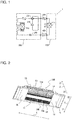
- Fig. 1 is a diagram illustrating an example of the configuration of an air-conditioning apparatus according to Embodiment 1 of the present invention.
- Fig. 1 illustrates an air-conditioning apparatus 1 as an example of a refrigeration cycle device.
- the air-conditioning apparatus 1 of Fig. 1 includes an outdoor unit 200 and an indoor unit 100.
- the outdoor unit 200 and the indoor unit 100 are connected by a gas refrigerant pipe 300 and a liquid refrigerant pipe 400.
- the outdoor unit 200 includes a compressor 210, a flow switching device 220, an outdoor heat exchanger 230, and an expansion valve 240.
- the compressor 210 compresses refrigerant sucked, and discharges the refrigerant.
- the flow switching device 220 is, for example, a four-way valve, and switches the flowing directions of refrigerant.
- the air-conditioning apparatus 1 switches operations between cooling operation and heating operation by switching the flowing directions of refrigerant.
- the outdoor heat exchanger 230 exchanges heat between refrigerant and air (outdoor air).
- the outdoor heat exchanger 230 acts as an evaporator during heating operation, and evaporates refrigerant into a gas phase.
- the outdoor heat exchanger 230 also acts as a condenser during cooling operation, and condenses refrigerant into a liquid phase.
- the expansion valve 240 is an expansion device (flow rate control unit).
- the expansion valve 240 acts as an expansion valve by adjusting the flow rate of refrigerant flowing through the expansion valve 240.
- the expansion valve 240 reduces the pressure of refrigerant flowing into the expansion valve 240.
- the expansion valve 240 adjusts its opening degree in accordance with an instruction of a controller (not shown) or any of other similar devices.
- the indoor unit 100 includes an indoor heat exchanger 110.
- the indoor heat exchanger 110 exchanges heat between refrigerant and air to be conditioned.
- the indoor heat exchanger 110 acts as a condenser during heating operation, and condenses refrigerant into a liquid phase.
- the indoor heat exchanger 110 also acts as an evaporator during cooling operation, and evaporates refrigerant into a gas phase.
- Fig. 2 is a perspective view illustrating the indoor unit of the air-conditioning apparatus according to Embodiment 1 of the present invention.
- the X-axis represents the longitudinal direction of the indoor unit 100
- the Y-axis represents the transverse direction of the indoor unit 100
- the Z-axis represents the height direction of the indoor unit 100.
- Z1 represents an upward direction or a direction toward a ceiling
- Z2 represents a downward direction or a direction toward an indoor space.
- the indoor unit 100 includes a body 10, a decorative panel 11, and filters 30 (described later).
- the above-described indoor heat exchanger 110 is accommodated in the body 10.
- the body 10 has an opening (not shown) at its lower face.
- the decorative panel 11 is attached to the body 10 to cover the opening.
- the filters 30 are disposed between the body 10 and the decorative panel 11.
- the indoor unit 100 illustrated in Fig. 2 is a ceiling concealed indoor unit in which the decorative panel 11 is exposed from a ceiling board and the body 10 is installed behind the ceiling board.
- the indoor unit 100 is not limited to a ceiling concealed indoor unit and may be a wall-mounted indoor unit or a floor-mounted indoor unit.
- the decorative panel 11 is made of a synthetic resin material and is formed in a rectangular shape in plan view.
- the longitudinal direction (X-axis direction), transverse direction (Y-axis direction), and height direction (Z-axis direction) of the decorative panel 11 respectively correspond to the longitudinal direction (X-axis direction), transverse direction (Y-axis direction), and height direction (Z-axis direction) of the above-described indoor unit 100.
- the decorative panel 11 has an air inlet grille 12 formed in a rectangular shape disposed at a location facing the opening of the body 10. As illustrated in Fig. 2 , the air inlet grille 12 is disposed at the center portion of the decorative panel 11 in the longitudinal direction (X-axis direction).
- the decorative panel 11 has side panels 15 provided on both sides of the air inlet grille 12 in the longitudinal direction (X-axis direction).
- the decorative panel 11 has an air outlet 13 along the longitudinal direction (X-axis direction) of the decorative panel 11 at one side (Y2 side) of the decorative panel 11 in the transverse direction (Y-axis direction).
- the air outlet 13 is used to pass air discharged from the body 10.
- the location of the air outlet 13 is not limited to the one side (Y2 side) of the decorative panel 11 in the transverse direction.
- the air outlet 13 may be formed at the other side (Y1 side) of the decorative panel 11 in the transverse direction. Alternatively, the location of the air outlet 13 is not limited to any one of the sides of the decorative panel 11 in the transverse direction.
- the air outlet 13 may be formed at each of the sides (Y1 side and Y2 side) of the decorative panel 11 in the transverse direction.
- An air flow flap 13a is disposed at the location of the air outlet 13 of the decorative panel 11. The air flow flap 13a is used to change the direction of air that is discharged from the body 10.
- Fig. 3 is a perspective view of the air inlet grille and the filter that are used in the indoor unit of the air-conditioning apparatus according to Embodiment 1 of the present invention when viewed from an inside of the body of the indoor unit.
- the air inlet grille 12 will be described with reference to Fig. 2 and Fig. 3 .
- the air inlet grille 12 has a front long-side wall portion 12a1, a rear long-side wall portion 12a2, and a plurality of short-side wall portions 12b.
- the front long-side wall portion 12a1 and the rear long-side wall portion 12a2 face each other.
- the plurality of short-side wall portions 12b are disposed perpendicularly to each of the front long-side wall portion 12a1 and the rear long-side wall portion 12a2.
- the air inlet grille 12 also has bottom portions 12c, and front hook receiving portions 12f and rear hook receiving portions 12j (described later).
- the bottom portions 12c are each surrounded by the front long-side wall portion 12a1, the rear long-side wall portion 12a2, and the short-side wall portions 12b.
- the front hook receiving portions 12f are located in respective grille corner portions 12e1 and the rear hook receiving portions 12j (described later) are located in respective grille corner portions 12e2, and the grille corner portions 12e1 and the grille corner portions 12e2 are located at the respective four corners of each of the bottom portions 12c.
- the rear long-side wall portion 12a2 forms a wall close to the air outlet 13 (Y2 side) in the air inlet grille 12.
- the front long-side wall portion 12a1 forms a wall opposite to the air outlet 13 (Y1 side).
- the air inlet grille 12 is formed in a rectangular shape in plan view.
- the longitudinal direction of the air inlet grille 12 is the same as the longitudinal direction (X-axis direction) of the decorative panel 11.
- the longitudinal direction (X-axis direction), transverse direction (Y-axis direction), and height direction (Z-axis direction) of the air inlet grille 12 respectively correspond to the longitudinal direction (X-axis direction), transverse direction (Y-axis direction), and height direction (Z-axis direction) of the indoor unit 100.
- the front long-side wall portion 12a1 and the rear long-side wall portion 12a2 correspond to the long-side wall portions of the present invention.
- the grille corner portions 12e1 and the grille corner portions 12e2 correspond to the grille corner portions of the present invention.
- the front hook receiving portions 12f and the rear hook receiving portions 12j correspond to the hook receiving portions of the present invention.
- an air inlet 14 is formed in the bottom portions 12c of the air inlet grille 12 along the longitudinal direction (X-axis direction).
- the air inlet 14 is a hole that extends through the air inlet grille 12 from a portion close to the body 10 (Z1 side) to a portion facing the indoor space (Z2 side).
- a plurality of parallel horizontal bars 14a and vertical bars 14b are provided inside the air inlet 14.
- the vertical bars 14b are perpendicular to the horizontal bars and connected to the horizontal bars. Indoor air is drawn into the body 10 through the air inlet 14 formed in the air inlet grille 12.
- Fig. 4 is an enlarged view of portion A illustrated in Fig. 3 .
- Fig. 5 is an enlarged sectional view of a portion taken along the line C-C in Fig. 3 .
- the front hook receiving portions 12f are disposed on each of the bottom portions 12c along the front long-side wall portion 12a1 that is one of the long-side wall portions of the air inlet grille 12.
- the front hook receiving portions 12f each have a front contact wall 12g and a front projecting portion 12h.
- the front contact wall 12g is a plate-shaped wall extending upward from the bottom portion 12c, and is provided to extend in the longitudinal direction (X-axis direction) of the air inlet grille 12.
- the front projecting portion 12h formed in a plate shape projects from the upper end of the front contact wall 12g toward the rear long-side wall portion 12a2 and faces the bottom portion 12c. As illustrated in Fig. 4 , the front projecting portion 12h is formed in a rectangular shape. As illustrated in Fig. 5 , the air inlet grille 12 has space S surrounded by the bottom portion 12c, the front contact wall 12g, and the front projecting portion 12h. As illustrated in Fig. 5 , the air inlet grille 12 further has a retaining rib 12i at a portion across from the front long-side wall portion 12a1. The retaining rib 12i extends upward from the bottom portion 12c to face the front contact wall 12g.
- Fig. 6 is an enlarged view of portion B illustrated in Fig. 3 .
- Fig. 7 is an enlarged sectional view of a portion taken along the line D-D in Fig. 3 .
- the rear hook receiving portion 12j is disposed on the rear long-side wall portion 12a2 that is the other one of the long-side wall portions of the air inlet grille 12.
- the rear hook receiving portion 12j projects from the rear long-side wall portion 12a2, and is provided to extend in the longitudinal direction (X-axis direction) of the air inlet grille 12.
- the rear hook receiving portion 12j has an inclined wall portion 12j1 and a bottom wall portion 12j2. As illustrated in Fig.
- the inclined wall portion 12j1 has an inclined surface toward an inside of the body 10 in such a manner that the width increases in the inclined wall portion 12j1 from the upper portion of the rear hook receiving portion 12j toward the lower portion of the rear hook receiving portion 12j.
- the bottom wall portion 12j2 is a surface facing each of the bottom portions 12c.
- the filters 30 will be described with reference to Fig. 3 to Fig. 7 .
- the filters 30 are separated from the air inlet grille 12.
- the filters 30 are each made of a synthetic resin material and each remove dust contained in air that is sucked into the body 10.
- the air inlet grille 12 has portions across one of the short-side wall portions 12b provided at a middle portion M of the air inlet grille 12, and the filter 30 is attached on each of the portions.
- the filters 30 are mounted to cover the air inlet 14 illustrated in Fig. 2 from the inside of the body 10.
- the filters 30 are each formed in a rectangular shape and each have a front long-side frame portion 30a1 and a rear long-side frame portion 30a2 that face each other and short-side frame portions 30b that face each other.
- the filters 30 each have front hook portions 31 (described later) located in respective filter corner portions 30e1 and rear hook portions 37 (described later) located in respective filter corner portions 30e2, and the filter corner portions 30e1 and the filter corner portions 30e2 are located at respective four corners of the filter 30.
- the front hook portions 31 and the rear hook portions 37 are engaged with the respective hook receiving portions.
- the longitudinal direction (X-axis direction), transverse direction (Y-axis direction), and height direction (Z-axis direction) of each of the filters 30 respectively correspond to the longitudinal direction (X-axis direction), transverse direction (Y-axis direction), and height direction (Z-axis direction) of the above-described indoor unit 100.
- the front long-side frame portions 30a1 and the rear long-side frame portions 30a2 correspond to the long-side frame portions of the present invention.
- the front hook portions 31 and the rear hook portions 37 correspond to the hook portions of the present invention.
- the front hook portion 31 is formed to project obliquely downward in the transverse direction of the filters 30 from the filter corner portion 30e1 located at each end of each of the front long-side frame portions 30a1 that is one of the corresponding one of the long-side frame portions.
- the front hook portions 31 each have a curved portion 32 the distal end of which curves, a first flat plate 33, and a second flat plate 34.
- the curved portion 32 is located at the distal end of the front hook portion 31 and curves in a top-and-bottom direction into a U-shape.
- the curved portion 32 has elasticity.
- the curved portion 32 has an upper wall portion 32b, a lower wall portion 32c, and a front wall portion 32a.
- the front wall portion 32a is the most distal end of the front hook portion 31 and connects the upper wall portion 32b to the lower wall portion 32c.
- the first flat plate 33 is a narrow long plate-shaped portion provided to be inclined between the upper wall portion 32b forming one end of the curved portion 32 and the front long-side frame portion 30a1.
- the second flat plate 34 is a narrow long plate-shaped portion provided to be connected with the lower wall portion 32c forming the other end of the curved portion 32 and is inclined in the same direction as a direction in which the first flat plate 33 is inclined.
- the curved portion 32 is formed to have a distance H1 between the outer surfaces of the upper wall portion 32b and lower wall portion 32c that is less than a distance H2 between the front projecting portion 12h and the bottom portion 12c.
- the front hook portion 31 is formed to have a distance W1 between the front wall portion 32a that is the most distal end portion of the front hook portion 31 and a proximal end portion 35 of the second flat plate that is greater than a distance W2 between the front projecting portion 12h and the retaining rib 12i.
- the rear hook portion 37 is formed to project downward from the filter corner portion 30e2 located at each end of each of the rear long-side frame portions 30a2 that is the other one of the corresponding one of the long-side frame portions.
- the rear hook portions 37 each have a downward wall portion 37a and an outer edge projecting portion 37b.
- the downward wall portion 37a projects downward.
- the outer edge projecting portion 37b projects from the lower end of the downward wall portion 37a in the transverse direction toward the outer edge of each of the filters 30.
- the upper wall portion 32b of the curved portion 32 faces the front projecting portion 12h of the front hook receiving portion 12f, and the front hook portion 31 is engaged with the front hook receiving portion 12f.
- the front hook portion 31 is inserted from the obliquely upper side (from the upper right side in Fig. 4 ).
- the front hook portion 31 is inserted in this manner, the distal end of the front hook portion 31 of the filter 30 is more easily inserted between the front projecting portion 12h and bottom portion 12c of the air inlet grille 12.
- the rear hook portions 37 of the filter 30 are each brought into contact with the corresponding one of the short-side wall portions 12b of the air inlet grille 12 in such a manner that the corresponding one of the short-side frame portions 30b of the filter 30 faces the short-side wall portion 12b of the air inlet grille 12.
- the outer edge projecting portion 37b of the rear hook portion 37 is placed under the rear hook receiving portion 12j in such a manner that the outer edge projecting portion 37b contacts with the rear long-side wall portion 12a2.
- the outer edge projecting portion 37b When the outer edge projecting portion 37b is placed under the rear hook receiving portion 12j, the outer edge projecting portion 37b faces the bottom wall portion 12j2 of the rear hook receiving portion 12j, and the rear hook portion 37 is engaged with the rear hook receiving portion 12j.
- the rear hook receiving portion 12j has the inclined wall portion 12j1. With the use of the inclined surface of the inclined wall portion 12j1, the outer edge projecting portion 37b is more easily placed under the rear hook receiving portion 12j.
- Each of the filters 30 is fixed and attached to the air inlet grille 12 when the front hook portions 31 are engaged with the front hook receiving portions 12f and the rear hook portions 37 are engaged with the rear hook receiving portions 12j.
- the air inlet grille has the hook receiving portions located in the respective grille corner portions each located at the corresponding one of the four corners of each of the bottom portions, the filter has hook portions in the respective filter corner portions each located at the corresponding one of the four corners of each of the filters, and the hook portions are engaged with the respective hook receiving portions.
- the filter may warp because of a temperature change or any of other causes during molding, and air containing dust that does not pass through the filter may be introduced into the indoor heat exchanger. In such a case, the indoor heat exchanger gets dusty, and the performance of the indoor unit decreases.
- the air inlet grille has the hook receiving portions located in the respective grille corner portions each located at the corresponding one of the four corners of each of the bottom portions, the filters each have the hook portions in the respective filter corner portions each located at the corresponding one of the four corners of the filter, and the hook portions are engaged with the respective hook receiving portions.
- the hook receiving portions include the front hook receiving portions disposed on the bottom portions along the front long-side wall portions.
- the front hook receiving portions each have the plate-shaped front contact wall extending upward from the bottom portion and the plate-shaped front projecting portion projecting from the upper end of the contact wall toward the other one of the long-side wall portions and facing the bottom portion.
- the hook receiving portions include the rear hook receiving portions disposed on the rear long-side wall portions.
- the rear hook receiving portions each have the inclined wall portion toward the inside of the body and having an inclined surface and projects from the rear long-side wall portion.
- the outer edge projecting portion is more easily placed under the rear hook receiving portion by pushing the rear hook portion with the use of the inclined surface of the inclined wall portion.
- the rear hook receiving portions each have the bottom wall portion having a surface that faces the bottom portion, and projects from the rear long-side wall portion. With such configuration, the rear hook portions are engaged with the rear hook receiving portions, and thus the filter is prevented from unintentionally coming off from the air inlet grille.
- the front hook portion is formed to project obliquely downward in the transverse direction of the filter from each end of each of the front long-side frame portions that is one of the corresponding one of the long-side frame portions. Consequently, the front hook portion is easily inserted into the space S, and the filter is quickly and easily attached to the air inlet grille.
- the front hook portions each have the curved portion, the first flat plate, and the second flat plate.
- the curved portion is located at the distal end of the front hook portion, and the distal end of the curved portion curves.
- the first flat plate is formed in a narrow long plate shape and is provided to be inclined between one end of the curved portion and the front long-side frame portion.
- the second flat plate is connected with the other end of the curved portion and is inclined in the same direction as the direction in which the first flat plate is inclined. Consequently, the front hook portion has elasticity. With the use of the elasticity of the front hook portion, the front hook portion is more easily inserted into the space S. Hence, the filter is quickly and easily attached to the air inlet grille. After the hook portion is engaged with the hook receiving portion, the front hook portion recovers in shape and is unlikely to come off from the hook receiving portion.
- the curved portions each have the upper wall portion and the lower wall portion, and is formed to have the distance H1 between the outer surfaces of the upper wall portion and lower wall portion that is less than the distance H2 between the front projecting portion and the bottom portion.
- the air inlet grille further has the retaining ribs each extending upward from the bottom portion to face the front contact wall, and the front hook portions are each formed to have the distance W1 between the most distal end portion of the front hook portion and the proximal end portion of the second flat plate that is greater than the distance W2 between the front projecting portion and the retaining rib. Consequently, when the front hook portion is inserted in the space S, movement of the proximal end portion of the filter in the transverse direction of the filter is restricted by the retaining rib. As a result, the front hook portion does not move in a direction to come off from the front hook receiving portion (rightward direction in Fig. 5 ), and the filter is prevented from unintentionally coming off from the air inlet grille.
- the rear hook portion is formed to project downward from the filter corner portion located at each end of each of the rear long-side frame portions. Consequently, after the front hook portion is attached to the air inlet grille in the oblique direction, the filter is easily attached to the air inlet grille by pushing the filter downward.
- the rear hook portions each have the downward wall portion and the outer edge projecting portion.
- the downward wall portion projects downward, and the outer edge projecting portion projects in the transverse direction from the lower end portion of the downward wall portion toward the outer edge of the filter. Consequently, the rear hook portion is engaged with the rear hook receiving portion, and the filter is prevented from unintentionally coming off from the air inlet grille.
- the front projecting portion 12h is formed in a rectangular shape; however, the shape of the front projecting portion 12h is not limited to a rectangular shape.
- the front projecting portion 12h only needs to project from the upper end of the front contact wall 12g toward the rear long-side wall portion 12a2.
- the front projecting portion 12h may be formed in a polygonal columnar shape having a bottom that faces the bottom portion 12c.
- the front projecting portion 12h may be formed in a semicircular columnar shape having a bottom that faces the bottom portion 12c.
- two filters 30 are attached to the air inlet grille; however, the number of filters 30 that are used in the indoor unit 100 is not limited to two.
- the number of filters 30 that are attached to the air inlet grille 12 only needs to match the number of grille corner portions formed.
- the number of the filters 30 may be two or more or may be one.
Landscapes
- Engineering & Computer Science (AREA)
- Chemical & Material Sciences (AREA)
- Combustion & Propulsion (AREA)
- Mechanical Engineering (AREA)
- General Engineering & Computer Science (AREA)
- Manufacturing & Machinery (AREA)
- Chemical Kinetics & Catalysis (AREA)
- Air Filters, Heat-Exchange Apparatuses, And Housings Of Air-Conditioning Units (AREA)
Description
- The present invention relates to an indoor unit for an air-conditioning apparatus, and an air-conditioning apparatus and, more particularly, to an air inlet grille and a filter that are used in an indoor unit for an air-conditioning apparatus.
- There has been an indoor unit for an air-conditioning apparatus, in which a filter is attached to an air inlet grille by causing hook portions of the filter to be engaged with hook receiving portions of the air inlet grille (see, for example, Patent Literature 1).
US6447389 B1 describes a rectangular grid plate comprising two engaging parts on each of the longer sides, configured to be engaged to the decorative panel. On each of the shorter side of the grid plate, one engaging slot for the filter frame is provided. The filter frame has one corresponding tab on each of its short sides, corresponding to the slots of the grid plate. The filter is inserted into the supporting grid and remains engaged by inserting the two tabs in the corresponding slots. The grid including the filter is then attached to the decorative panel by clamping the four engaging parts. - Patent Literature 1: Japanese Unexamined Patent Application Publication No.
09-196460 - In an existing indoor unit, hook portions are disposed at the periphery of a filter, and hook receiving portions are disposed on the inner back face of an air inlet grille. However, when the filter is attached to the air inlet grille, it is sometimes difficult to set the position of the filter to the air inlet grille.
- The present invention is made to solve the above-described problem, and provides an indoor unit for an air-conditioning apparatus, and an air-conditioning apparatus that make it easy to set the position of a filter to an air inlet grille when the filter is attached to the air inlet grille.
- An indoor unit for an air-conditioning apparatus according to the present invention is defined in claim 1. The dependent claims define preferred embodiments of the invention.
- The indoor unit for an air conditioner according to the invention includes a body, a decorative panel, and a filter. The body has an opening. The decorative panel is attached to the body to cover the opening. The filter is disposed between the body and the decorative panel. The decorative panel has an air inlet grille formed in a rectangular shape disposed at a location that faces the opening of the body. The air inlet grille has long-side wall portions that face each other, a plurality of short-side wall portions, a bottom portion, and hook receiving portions. The plurality of short-side wall portions are disposed perpendicularly to each of the long-side wall portions. The bottom portion is surrounded by the long-side wall portions and the plurality of short-side wall portions. The hook receiving portions are located in respective grille corner portions each located at the corresponding one of four corners of the bottom portion. The filter is formed in a rectangular shape. The filter has hook portions in respective filter corner portions each located at the corresponding one of four corners of the filter, and the hook portions are engaged with the respective hook receiving portions.
- In the indoor unit for an air-conditioning apparatus according to an embodiment of the present invention, the air inlet grille has the hook receiving portions located in the respective grille corner portions each located at the corresponding one of four corners of the bottom portion, the filter has the hook portions in the respective filter corner portions each located at the corresponding one of four corners of the filter, and the hook portions are engaged with the respective hook receiving portions. As a result, a position of the filter is easily set when the filter is attached, and thus the filter is quickly and easily attached to the air inlet grille. Consequently, workability when the filter is attached to the air inlet grille is improved.
-
- [
Fig. 1] Fig. 1 is a diagram illustrating an example of the configuration of an air-conditioning apparatus according to Embodiment 1 of the present invention. - [
Fig. 2] Fig. 2 is a perspective view illustrating an indoor unit of the air-conditioning apparatus according to Embodiment 1 of the present invention. - [
Fig. 3] Fig. 3 is a perspective view of an air inlet grille and a filter that are used in the indoor unit of the air-conditioning apparatus according to Embodiment 1 of the present invention when viewed from an inside of a body of the indoor unit. - [
Fig. 4] Fig. 4 is an enlarged view of portion A illustrated inFig. 3 . - [
Fig. 5] Fig. 5 is an enlarged sectional view of a portion taken along the line C-C inFig. 3 . - [
Fig. 6] Fig. 6 is an enlarged view of portion B illustrated inFig. 3 . - [
Fig. 7] Fig. 7 is an enlarged sectional view of a portion taken along the line D-D inFig. 3 . - Hereinafter, an indoor unit for an air-conditioning apparatus, and an air-conditioning apparatus according to an embodiment of the present invention will be described with reference to, for example, the drawings. In the drawings described hereinafter, the same reference signs denote the same or corresponding elements, and this note applies to the full text of the following description. The modes of elements described in the full text of the specification are only illustrative, and modes of elements are not limited to the modes described in the specification. In the drawings, the relations of dimensions among elements can be different from the actual ones. For easy understanding, terms that represent directions (for example, "upper", "lower", "right", "left", "front", "rear", and others) are used where appropriate; however, these terms are intended for illustration, and the present invention is not limited to these terms.
-
Fig. 1 is a diagram illustrating an example of the configuration of an air-conditioning apparatus according to Embodiment 1 of the present invention.Fig. 1 illustrates an air-conditioning apparatus 1 as an example of a refrigeration cycle device. The air-conditioning apparatus 1 ofFig. 1 includes anoutdoor unit 200 and anindoor unit 100. Theoutdoor unit 200 and theindoor unit 100 are connected by agas refrigerant pipe 300 and aliquid refrigerant pipe 400. - The
outdoor unit 200 includes acompressor 210, aflow switching device 220, anoutdoor heat exchanger 230, and anexpansion valve 240. Thecompressor 210 compresses refrigerant sucked, and discharges the refrigerant. Theflow switching device 220 is, for example, a four-way valve, and switches the flowing directions of refrigerant. The air-conditioning apparatus 1 switches operations between cooling operation and heating operation by switching the flowing directions of refrigerant. The outdoor heat exchanger 230 exchanges heat between refrigerant and air (outdoor air). Theoutdoor heat exchanger 230 acts as an evaporator during heating operation, and evaporates refrigerant into a gas phase. Theoutdoor heat exchanger 230 also acts as a condenser during cooling operation, and condenses refrigerant into a liquid phase. Theexpansion valve 240 is an expansion device (flow rate control unit). Theexpansion valve 240 acts as an expansion valve by adjusting the flow rate of refrigerant flowing through theexpansion valve 240. Theexpansion valve 240 reduces the pressure of refrigerant flowing into theexpansion valve 240. For example, when theexpansion valve 240 is an electronic expansion valve or any of other similar types, theexpansion valve 240 adjusts its opening degree in accordance with an instruction of a controller (not shown) or any of other similar devices. - The
indoor unit 100 includes anindoor heat exchanger 110. Theindoor heat exchanger 110 exchanges heat between refrigerant and air to be conditioned. Theindoor heat exchanger 110 acts as a condenser during heating operation, and condenses refrigerant into a liquid phase. Theindoor heat exchanger 110 also acts as an evaporator during cooling operation, and evaporates refrigerant into a gas phase. -
Fig. 2 is a perspective view illustrating the indoor unit of the air-conditioning apparatus according to Embodiment 1 of the present invention. InFig. 2 , the X-axis represents the longitudinal direction of theindoor unit 100, the Y-axis represents the transverse direction of theindoor unit 100, and the Z-axis represents the height direction of theindoor unit 100. In the Z-axis, Z1 represents an upward direction or a direction toward a ceiling, and Z2 represents a downward direction or a direction toward an indoor space. - The
indoor unit 100 includes abody 10, adecorative panel 11, and filters 30 (described later). The above-describedindoor heat exchanger 110 is accommodated in thebody 10. Thebody 10 has an opening (not shown) at its lower face. Thedecorative panel 11 is attached to thebody 10 to cover the opening. Thefilters 30 are disposed between thebody 10 and thedecorative panel 11. Theindoor unit 100 illustrated inFig. 2 is a ceiling concealed indoor unit in which thedecorative panel 11 is exposed from a ceiling board and thebody 10 is installed behind the ceiling board. Theindoor unit 100 is not limited to a ceiling concealed indoor unit and may be a wall-mounted indoor unit or a floor-mounted indoor unit. - The
decorative panel 11 is made of a synthetic resin material and is formed in a rectangular shape in plan view. The longitudinal direction (X-axis direction), transverse direction (Y-axis direction), and height direction (Z-axis direction) of thedecorative panel 11 respectively correspond to the longitudinal direction (X-axis direction), transverse direction (Y-axis direction), and height direction (Z-axis direction) of the above-describedindoor unit 100. Thedecorative panel 11 has anair inlet grille 12 formed in a rectangular shape disposed at a location facing the opening of thebody 10. As illustrated inFig. 2 , theair inlet grille 12 is disposed at the center portion of thedecorative panel 11 in the longitudinal direction (X-axis direction). Thedecorative panel 11 hasside panels 15 provided on both sides of theair inlet grille 12 in the longitudinal direction (X-axis direction). Thedecorative panel 11 has anair outlet 13 along the longitudinal direction (X-axis direction) of thedecorative panel 11 at one side (Y2 side) of thedecorative panel 11 in the transverse direction (Y-axis direction). Theair outlet 13 is used to pass air discharged from thebody 10. The location of theair outlet 13 is not limited to the one side (Y2 side) of thedecorative panel 11 in the transverse direction. Theair outlet 13 may be formed at the other side (Y1 side) of thedecorative panel 11 in the transverse direction. Alternatively, the location of theair outlet 13 is not limited to any one of the sides of thedecorative panel 11 in the transverse direction. Theair outlet 13 may be formed at each of the sides (Y1 side and Y2 side) of thedecorative panel 11 in the transverse direction. Anair flow flap 13a is disposed at the location of theair outlet 13 of thedecorative panel 11. Theair flow flap 13a is used to change the direction of air that is discharged from thebody 10. -
Fig. 3 is a perspective view of the air inlet grille and the filter that are used in the indoor unit of the air-conditioning apparatus according to Embodiment 1 of the present invention when viewed from an inside of the body of the indoor unit. Theair inlet grille 12 will be described with reference toFig. 2 andFig. 3 . Theair inlet grille 12 has a front long-side wall portion 12a1, a rear long-side wall portion 12a2, and a plurality of short-side wall portions 12b. The front long-side wall portion 12a1 and the rear long-side wall portion 12a2 face each other. The plurality of short-side wall portions 12b are disposed perpendicularly to each of the front long-side wall portion 12a1 and the rear long-side wall portion 12a2. Theair inlet grille 12 also hasbottom portions 12c, and fronthook receiving portions 12f and rearhook receiving portions 12j (described later). Thebottom portions 12c are each surrounded by the front long-side wall portion 12a1, the rear long-side wall portion 12a2, and the short-side wall portions 12b. The fronthook receiving portions 12f (described later) are located in respective grille corner portions 12e1 and the rearhook receiving portions 12j (described later) are located in respective grille corner portions 12e2, and the grille corner portions 12e1 and the grille corner portions 12e2 are located at the respective four corners of each of thebottom portions 12c. The rear long-side wall portion 12a2 forms a wall close to the air outlet 13 (Y2 side) in theair inlet grille 12. The front long-side wall portion 12a1 forms a wall opposite to the air outlet 13 (Y1 side). Theair inlet grille 12 is formed in a rectangular shape in plan view. The longitudinal direction of theair inlet grille 12 is the same as the longitudinal direction (X-axis direction) of thedecorative panel 11. That is, the longitudinal direction (X-axis direction), transverse direction (Y-axis direction), and height direction (Z-axis direction) of theair inlet grille 12 respectively correspond to the longitudinal direction (X-axis direction), transverse direction (Y-axis direction), and height direction (Z-axis direction) of theindoor unit 100. The front long-side wall portion 12a1 and the rear long-side wall portion 12a2 correspond to the long-side wall portions of the present invention. The grille corner portions 12e1 and the grille corner portions 12e2 correspond to the grille corner portions of the present invention. The fronthook receiving portions 12f and the rearhook receiving portions 12j correspond to the hook receiving portions of the present invention. - As illustrated in
Fig. 2 , anair inlet 14 is formed in thebottom portions 12c of theair inlet grille 12 along the longitudinal direction (X-axis direction). Theair inlet 14 is a hole that extends through theair inlet grille 12 from a portion close to the body 10 (Z1 side) to a portion facing the indoor space (Z2 side). A plurality of parallelhorizontal bars 14a andvertical bars 14b are provided inside theair inlet 14. Thevertical bars 14b are perpendicular to the horizontal bars and connected to the horizontal bars. Indoor air is drawn into thebody 10 through theair inlet 14 formed in theair inlet grille 12. -
Fig. 4 is an enlarged view of portion A illustrated inFig. 3 .Fig. 5 is an enlarged sectional view of a portion taken along the line C-C inFig. 3 . The fronthook receiving portions 12f are disposed on each of thebottom portions 12c along the front long-side wall portion 12a1 that is one of the long-side wall portions of theair inlet grille 12. The fronthook receiving portions 12f each have afront contact wall 12g and a front projectingportion 12h. Thefront contact wall 12g is a plate-shaped wall extending upward from thebottom portion 12c, and is provided to extend in the longitudinal direction (X-axis direction) of theair inlet grille 12. The front projectingportion 12h formed in a plate shape projects from the upper end of thefront contact wall 12g toward the rear long-side wall portion 12a2 and faces thebottom portion 12c. As illustrated inFig. 4 , thefront projecting portion 12h is formed in a rectangular shape. As illustrated inFig. 5 , theair inlet grille 12 has space S surrounded by thebottom portion 12c, thefront contact wall 12g, and the front projectingportion 12h. As illustrated inFig. 5 , theair inlet grille 12 further has a retainingrib 12i at a portion across from the front long-side wall portion 12a1. The retainingrib 12i extends upward from thebottom portion 12c to face thefront contact wall 12g. -
Fig. 6 is an enlarged view of portion B illustrated inFig. 3 .Fig. 7 is an enlarged sectional view of a portion taken along the line D-D inFig. 3 . As illustrated inFig. 6 , the rearhook receiving portion 12j is disposed on the rear long-side wall portion 12a2 that is the other one of the long-side wall portions of theair inlet grille 12. The rearhook receiving portion 12j projects from the rear long-side wall portion 12a2, and is provided to extend in the longitudinal direction (X-axis direction) of theair inlet grille 12. The rearhook receiving portion 12j has an inclined wall portion 12j1 and a bottom wall portion 12j2. As illustrated inFig. 7 , in the section of the rear long-side wall portion 12a2, the inclined wall portion 12j1 has an inclined surface toward an inside of thebody 10 in such a manner that the width increases in the inclined wall portion 12j1 from the upper portion of the rearhook receiving portion 12j toward the lower portion of the rearhook receiving portion 12j. The bottom wall portion 12j2 is a surface facing each of thebottom portions 12c. - Next, the
filters 30 will be described with reference toFig. 3 to Fig. 7 . InFig. 4 andFig. 6 , to illustrate the configuration of theair inlet grille 12, thefilters 30 are separated from theair inlet grille 12. Thefilters 30 are each made of a synthetic resin material and each remove dust contained in air that is sucked into thebody 10. As illustrated inFig. 3 , theair inlet grille 12 has portions across one of the short-side wall portions 12b provided at a middle portion M of theair inlet grille 12, and thefilter 30 is attached on each of the portions. Thefilters 30 are mounted to cover theair inlet 14 illustrated inFig. 2 from the inside of thebody 10. Thefilters 30 are each formed in a rectangular shape and each have a front long-side frame portion 30a1 and a rear long-side frame portion 30a2 that face each other and short-side frame portions 30b that face each other. Thefilters 30 each have front hook portions 31 (described later) located in respective filter corner portions 30e1 and rear hook portions 37 (described later) located in respective filter corner portions 30e2, and the filter corner portions 30e1 and the filter corner portions 30e2 are located at respective four corners of thefilter 30. Thefront hook portions 31 and therear hook portions 37 are engaged with the respective hook receiving portions. The longitudinal direction (X-axis direction), transverse direction (Y-axis direction), and height direction (Z-axis direction) of each of thefilters 30 respectively correspond to the longitudinal direction (X-axis direction), transverse direction (Y-axis direction), and height direction (Z-axis direction) of the above-describedindoor unit 100. The front long-side frame portions 30a1 and the rear long-side frame portions 30a2 correspond to the long-side frame portions of the present invention. Thefront hook portions 31 and therear hook portions 37 correspond to the hook portions of the present invention. - As illustrated in
Fig. 4 , thefront hook portion 31 is formed to project obliquely downward in the transverse direction of thefilters 30 from the filter corner portion 30e1 located at each end of each of the front long-side frame portions 30a1 that is one of the corresponding one of the long-side frame portions. As illustrated inFig. 5 , thefront hook portions 31 each have acurved portion 32 the distal end of which curves, a firstflat plate 33, and a secondflat plate 34. Thecurved portion 32 is located at the distal end of thefront hook portion 31 and curves in a top-and-bottom direction into a U-shape. Thecurved portion 32 has elasticity. Thecurved portion 32 has anupper wall portion 32b, alower wall portion 32c, and afront wall portion 32a. Thefront wall portion 32a is the most distal end of thefront hook portion 31 and connects theupper wall portion 32b to thelower wall portion 32c. The firstflat plate 33 is a narrow long plate-shaped portion provided to be inclined between theupper wall portion 32b forming one end of thecurved portion 32 and the front long-side frame portion 30a1. The secondflat plate 34 is a narrow long plate-shaped portion provided to be connected with thelower wall portion 32c forming the other end of thecurved portion 32 and is inclined in the same direction as a direction in which the firstflat plate 33 is inclined. Thecurved portion 32 is formed to have a distance H1 between the outer surfaces of theupper wall portion 32b andlower wall portion 32c that is less than a distance H2 between the front projectingportion 12h and thebottom portion 12c. Thefront hook portion 31 is formed to have a distance W1 between thefront wall portion 32a that is the most distal end portion of thefront hook portion 31 and aproximal end portion 35 of the second flat plate that is greater than a distance W2 between the front projectingportion 12h and the retainingrib 12i. - As illustrated in
Fig. 3 andFig. 6 , therear hook portion 37 is formed to project downward from the filter corner portion 30e2 located at each end of each of the rear long-side frame portions 30a2 that is the other one of the corresponding one of the long-side frame portions. As illustrated inFig. 6 andFig. 7 , therear hook portions 37 each have adownward wall portion 37a and an outeredge projecting portion 37b. Thedownward wall portion 37a projects downward. The outeredge projecting portion 37b projects from the lower end of thedownward wall portion 37a in the transverse direction toward the outer edge of each of thefilters 30. - Next, attaching of the
filters 30 to theair inlet grille 12 will be described with reference toFig. 4 andFig. 6 . When each of thefilters 30 is attached to theair inlet grille 12, first, thefront hook portions 31 of thefilter 30 are each brought into contact with the corresponding one of the short-side wall portions 12b of theair inlet grille 12 in such a manner that the short-side frame portions 30b of thefilter 30 each face the corresponding one of the short-side wall portions 12b of theair inlet grille 12. Subsequently, thefront hook portions 31 are each inserted into the corresponding one of the spaces S in such a manner that thefront hook portion 31 contacts with thefront contact wall 12g of the corresponding one of the fronthook receiving portions 12f. Once thefront hook portion 31 is inserted in the space S, theupper wall portion 32b of thecurved portion 32 faces thefront projecting portion 12h of the fronthook receiving portion 12f, and thefront hook portion 31 is engaged with the fronthook receiving portion 12f. As represented by the arrow inFig. 4 , when thefront hook portion 31 of one of thefilters 30 is inserted below thefront projecting portion 12h of theair inlet grille 12, thefront hook portion 31 is inserted from the obliquely upper side (from the upper right side inFig. 4 ). When thefront hook portion 31 is inserted in this manner, the distal end of thefront hook portion 31 of thefilter 30 is more easily inserted between the front projectingportion 12h andbottom portion 12c of theair inlet grille 12. When thefront hook portion 31 is inserted in the space S, movement of theproximal end portion 35 of thefilter 30 in the transverse direction of thefilter 30 is restricted by the retainingrib 12i. Thus, thefront hook portion 31 does not move in a direction to come off from the fronthook receiving portion 12f (rightward direction in the drawing), and thefilter 30 is prevented from coming off from theair inlet grille 12. - Subsequently, the
rear hook portions 37 of thefilter 30 are each brought into contact with the corresponding one of the short-side wall portions 12b of theair inlet grille 12 in such a manner that the corresponding one of the short-side frame portions 30b of thefilter 30 faces the short-side wall portion 12b of theair inlet grille 12. Then, the outeredge projecting portion 37b of therear hook portion 37 is placed under the rearhook receiving portion 12j in such a manner that the outeredge projecting portion 37b contacts with the rear long-side wall portion 12a2. When the outeredge projecting portion 37b is placed under the rearhook receiving portion 12j, the outeredge projecting portion 37b faces the bottom wall portion 12j2 of the rearhook receiving portion 12j, and therear hook portion 37 is engaged with the rearhook receiving portion 12j. The rearhook receiving portion 12j has the inclined wall portion 12j1. With the use of the inclined surface of the inclined wall portion 12j1, the outeredge projecting portion 37b is more easily placed under the rearhook receiving portion 12j. - Each of the
filters 30 is fixed and attached to theair inlet grille 12 when thefront hook portions 31 are engaged with the fronthook receiving portions 12f and therear hook portions 37 are engaged with the rearhook receiving portions 12j. - As described above, in the
indoor unit 100, the air inlet grille has the hook receiving portions located in the respective grille corner portions each located at the corresponding one of the four corners of each of the bottom portions, the filter has hook portions in the respective filter corner portions each located at the corresponding one of the four corners of each of the filters, and the hook portions are engaged with the respective hook receiving portions. As a result, the position of the filter is easily set when the filter is attached, and thus the filter is quickly and easily attached to the air inlet grille. Consequently, workability when the filter is attached to the air inlet grille is improved. - The filter may warp because of a temperature change or any of other causes during molding, and air containing dust that does not pass through the filter may be introduced into the indoor heat exchanger. In such a case, the indoor heat exchanger gets dusty, and the performance of the indoor unit decreases. In the
indoor unit 100, the air inlet grille has the hook receiving portions located in the respective grille corner portions each located at the corresponding one of the four corners of each of the bottom portions, the filters each have the hook portions in the respective filter corner portions each located at the corresponding one of the four corners of the filter, and the hook portions are engaged with the respective hook receiving portions. As a result, a warpage of the filter is corrected as a result of the corners of the filter being held, and indoor air that passes through the air inlet grille is caused to pass through the filter without any leakage. - The hook receiving portions include the front hook receiving portions disposed on the bottom portions along the front long-side wall portions. The front hook receiving portions each have the plate-shaped front contact wall extending upward from the bottom portion and the plate-shaped front projecting portion projecting from the upper end of the contact wall toward the other one of the long-side wall portions and facing the bottom portion. As a result, the position of the filter is easily set when the filter is attached, and the filter is quickly and easily attached to the air inlet grille. Consequently, workability when the filter is attached to the air inlet grille is improved. In addition, the front hook portions are engaged with the front hook receiving portions, and thus the filter is prevented from unintentionally coming off from the air inlet grille.
- The hook receiving portions include the rear hook receiving portions disposed on the rear long-side wall portions. The rear hook receiving portions each have the inclined wall portion toward the inside of the body and having an inclined surface and projects from the rear long-side wall portion. In a process of attaching the filter to the air inlet grille, the outer edge projecting portion is more easily placed under the rear hook receiving portion by pushing the rear hook portion with the use of the inclined surface of the inclined wall portion. As a result, the filter is quickly and easily attached to the air inlet grille, and thus workability when the filter is attached to the air inlet grille is improved. The rear hook receiving portions each have the bottom wall portion having a surface that faces the bottom portion, and projects from the rear long-side wall portion. With such configuration, the rear hook portions are engaged with the rear hook receiving portions, and thus the filter is prevented from unintentionally coming off from the air inlet grille.
- The front hook portion is formed to project obliquely downward in the transverse direction of the filter from each end of each of the front long-side frame portions that is one of the corresponding one of the long-side frame portions. Consequently, the front hook portion is easily inserted into the space S, and the filter is quickly and easily attached to the air inlet grille.
- The front hook portions each have the curved portion, the first flat plate, and the second flat plate. The curved portion is located at the distal end of the front hook portion, and the distal end of the curved portion curves. The first flat plate is formed in a narrow long plate shape and is provided to be inclined between one end of the curved portion and the front long-side frame portion. The second flat plate is connected with the other end of the curved portion and is inclined in the same direction as the direction in which the first flat plate is inclined. Consequently, the front hook portion has elasticity. With the use of the elasticity of the front hook portion, the front hook portion is more easily inserted into the space S. Hence, the filter is quickly and easily attached to the air inlet grille. After the hook portion is engaged with the hook receiving portion, the front hook portion recovers in shape and is unlikely to come off from the hook receiving portion.
- The curved portions each have the upper wall portion and the lower wall portion, and is formed to have the distance H1 between the outer surfaces of the upper wall portion and lower wall portion that is less than the distance H2 between the front projecting portion and the bottom portion. As a result, the hook portion is more easily inserted into the hook receiving portion when the filter is attached, and thus the filter is quickly and easily attached to the air inlet grille. Consequently, workability when the filter is attached to the air inlet grille is improved.
- The air inlet grille further has the retaining ribs each extending upward from the bottom portion to face the front contact wall, and the front hook portions are each formed to have the distance W1 between the most distal end portion of the front hook portion and the proximal end portion of the second flat plate that is greater than the distance W2 between the front projecting portion and the retaining rib. Consequently, when the front hook portion is inserted in the space S, movement of the proximal end portion of the filter in the transverse direction of the filter is restricted by the retaining rib. As a result, the front hook portion does not move in a direction to come off from the front hook receiving portion (rightward direction in
Fig. 5 ), and the filter is prevented from unintentionally coming off from the air inlet grille. - The rear hook portion is formed to project downward from the filter corner portion located at each end of each of the rear long-side frame portions. Consequently, after the front hook portion is attached to the air inlet grille in the oblique direction, the filter is easily attached to the air inlet grille by pushing the filter downward.
- The rear hook portions each have the downward wall portion and the outer edge projecting portion. The downward wall portion projects downward, and the outer edge projecting portion projects in the transverse direction from the lower end portion of the downward wall portion toward the outer edge of the filter. Consequently, the rear hook portion is engaged with the rear hook receiving portion, and the filter is prevented from unintentionally coming off from the air inlet grille.
- The embodiments of the present invention are not limited to Embodiment 1. Various modifications may be added. For example, in
Fig. 4 , thefront projecting portion 12h is formed in a rectangular shape; however, the shape of the front projectingportion 12h is not limited to a rectangular shape. The front projectingportion 12h only needs to project from the upper end of thefront contact wall 12g toward the rear long-side wall portion 12a2. For example, thefront projecting portion 12h may be formed in a polygonal columnar shape having a bottom that faces thebottom portion 12c. Alternatively, thefront projecting portion 12h may be formed in a semicircular columnar shape having a bottom that faces thebottom portion 12c. InFig. 3 , twofilters 30 are attached to the air inlet grille; however, the number offilters 30 that are used in theindoor unit 100 is not limited to two. The number offilters 30 that are attached to theair inlet grille 12 only needs to match the number of grille corner portions formed. For example, the number of thefilters 30 may be two or more or may be one. - 1 air-
conditioning apparatus 10body 11decorative panel 12 air inlet grille 12a1 front long-side wall portion 12a2 rear long-side wall portion 12b short-side wall portion 12c bottom portion 12e1 grille corner portion 12e2grille corner portion 12f fronthook receiving portion 12gfront contact wall 12hfront projecting portion 12i retaining rib 12j rear hook receiving portion 12j1 inclined wall portion 12j2bottom wall portion 13air outlet 13aair flow flap 14air inlet 14ahorizontal bar 14bvertical bar 15side panel 30 filter 30a1 front long-side frame portion 30a2 rear long-side frame portion 30b short-side frame portion 30e1 filter corner portion 30e2 filtercorner portion 31front hook portion 32curved portion 32afront wall portion 32bupper wall portion 32clower wall portion 33 firstflat plate 34 secondflat plate 35proximal end portion 37rear hook portion 37adownward wall portion 37b outeredge projecting portion 100indoor unit 110indoor heat exchanger 200outdoor unit 210compressor 220flow switching device 230outdoor heat exchanger 240expansion valve 300gas refrigerant pipe 400 liquid refrigerant pipe
Claims (10)
- An indoor unit (100) for an air-conditioning apparatus, the indoor unit (100) comprising:a body (10) having an opening;a decorative panel (11) attached to the body (10) to cover the opening; anda filter (30) disposed between the body (10) and the decorative panel (11),the decorative panel (11) having an air inlet grille (12) formed in a rectangular shape disposed at a location that faces the opening of the body (10),the air inlet grille (12) having long-side wall portions (12a1, 12a2) that face each other, a plurality of short-side wall portions (12b), a bottom portion (12c), and hook receiving portions (12f, 12j), the plurality of short-side wall portions (12b) being disposed perpendicularly to each of the long-side wall portions (12a1, 12a2), the bottom portion (12c) being surrounded by the long-side wall portions (12a1, 12a2) and the plurality of short-side wall portions (12b), the hook receiving portions (12f, 12j) being located in respective grille corner portions (12e1, 12e2) each located at a corresponding one of four corners of the bottom portion (12c),the hook receiving portions (12f, 12j) including front hook receiving portions (12f) disposed on the bottom portion (12c) along a front long-side wall portion (12a1) that is one of the long-side wall portions (12a1, 12a2) of the air inlet grille (12),the front hook receiving portions (12f) each having a front contact wall (12g) formed in a plate shape and a front projecting portion (12h) formed in a plate shape, the front contact wall (12g) extending upward from the bottom portion (12c), the front projecting portion (12h) projecting from an upper end of the front contact wall (12g) toward an other one of the long-side wall portions (12a1, 12a2) and facing the bottom portion (12c),the filter (30) being formed in a rectangular shape and having hook portions (31, 37) in respective filter corner portions (30e1, 30e2) each located at a corresponding one of four corners of the filter (30), the hook portions (31, 37) being engaged with the respective hook receiving portions (12f, 12j).
- The indoor unit (100) for an air-conditioning apparatus of claim 1, wherein
the hook receiving portions (12f, 12j) include rear hook receiving portions (12j) disposed on a rear long-side wall portion (12a2) that is the other one of the long-side wall portions (12a1, 12a2) of the air inlet grille (12), and
the rear hook receiving portions (12j) each have an inclined wall portion (12j1) and a bottom wall portion (12j2), the inclined wall portion (12j1) toward an inside of the body (10) and having an inclined surface, the bottom wall portion (12j2) having a surface facing the bottom portion (12c), the rear hook receiving portions (12j) projecting from the rear long-side wall portion (12a2) of the air inlet grille (12). - The indoor unit (100) for an air-conditioning apparatus of claim 1 or 2, wherein
the filter (30) has long-side frame portions (30a1, 30a2) that face each other and short-side frame portions that face each other, and
the hook portions (31, 37) include a front hook portion (31) formed to project obliquely downward in a transverse direction of the filter (30) from each end of a front long-side frame portion (30a1) that is one of the long-side frame portions (30a1, 30a2). - The indoor unit (100) for an air-conditioning apparatus of claim 3, wherein the front hook portion (31) has a curved portion (32), a first flat plate (33) formed in a narrow long plate shape, and a second flat plate (34), the curved portion (32) being located at a distal end of the front hook portion (31) and whose distal end is curved, the first flat plate (33) being provided and inclined between one end of the curved portion (32) and the front long-side frame portion (30a1), the second flat plate (34) being provided to be connected to an other end of the curved portion (32) and inclined in a same direction as a direction in which the first flat plate (33) is inclined.
- The indoor unit (100) for an air-conditioning apparatus of claim 4, wherein the curved portion (32) has an upper wall portion (32b) and a lower wall portion (32c), and is formed to have a distance H1 between an outer surface of the upper wall portion (32b) and an outer surface of the lower wall portion (32c) that is less than a distance H2 between the front projecting portion (12h) and the bottom portion (12c).
- The indoor unit (100) for an air-conditioning apparatus of claim 5, wherein
the air inlet grille (12) further has a retaining rib (12i) extending upward from the bottom portion (12c) to face the front contact wall (12g), and
the front hook portion (31) is formed to have a distance W1 between a most distal end portion of the front hook portion (31) and a proximal end portion (35) of the second flat plate (34) that is greater than a distance W2 between the front projecting portion (12h) and the retaining rib (12i). - The indoor unit (100) for an air-conditioning apparatus of any one of claims 3 to 6, wherein the hook portions (31, 37) include a rear hook portion (37) formed to project downward from a corresponding one of the filter corner portions (30e1, 30e2) located at each end of a rear long-side frame portion (30a2) that is an other one of the long-side frame portions (30a1, 30a2).
- The indoor unit (100) for an air-conditioning apparatus of claim 7, wherein the rear hook portion (37) has a downward wall portion (37a) projecting downward and an outer edge projecting portion (37b) projecting in the transverse direction from a lower end of the downward wall portion (37a) toward an outer edge of the filter (30).
- The indoor unit (100) for an air-conditioning apparatus of any one of claims 1 to 8, wherein the filter (30) comprises a plurality of filters (30) that are disposed on the air inlet grille (12).
- An air-conditioning apparatus (1) comprising the indoor unit (100) for an air-conditioning apparatus of any one of claims 1 to 9.
Applications Claiming Priority (1)
| Application Number | Priority Date | Filing Date | Title |
|---|---|---|---|
| PCT/JP2017/003604 WO2018142508A1 (en) | 2017-02-01 | 2017-02-01 | Air conditioner indoor unit and air conditioner |
Publications (3)
| Publication Number | Publication Date |
|---|---|
| EP3578900A1 EP3578900A1 (en) | 2019-12-11 |
| EP3578900A4 EP3578900A4 (en) | 2020-02-26 |
| EP3578900B1 true EP3578900B1 (en) | 2021-01-06 |
Family
ID=63040347
Family Applications (1)
| Application Number | Title | Priority Date | Filing Date |
|---|---|---|---|
| EP17894823.8A Active EP3578900B1 (en) | 2017-02-01 | 2017-02-01 | Air conditioner indoor unit and air conditioner |
Country Status (5)
| Country | Link |
|---|---|
| US (1) | US11384955B2 (en) |
| EP (1) | EP3578900B1 (en) |
| JP (1) | JP6698886B2 (en) |
| CN (1) | CN208794688U (en) |
| WO (1) | WO2018142508A1 (en) |
Families Citing this family (1)
| Publication number | Priority date | Publication date | Assignee | Title |
|---|---|---|---|---|
| JP6716007B2 (en) * | 2017-02-23 | 2020-07-01 | 三菱電機株式会社 | Air conditioner |
Family Cites Families (17)
| Publication number | Priority date | Publication date | Assignee | Title |
|---|---|---|---|---|
| FR2249571A5 (en) * | 1973-10-26 | 1975-05-23 | Intermat France | Quick-release clamp for air filter panel housing - employs profiled leaf spring as retractable bolt |
| JPH076687B2 (en) * | 1989-11-10 | 1995-01-30 | 三菱電機株式会社 | Ceiling embedded air conditioner |
| JP3021722B2 (en) * | 1991-03-25 | 2000-03-15 | 三洋電機株式会社 | Air filter mounting device |
| JP3043141B2 (en) * | 1991-11-15 | 2000-05-22 | 三洋電機株式会社 | Air conditioner |
| JP3317074B2 (en) | 1995-02-28 | 2002-08-19 | 三菱電機株式会社 | Air conditioner filter mounting device |
| JP3063609B2 (en) | 1996-01-22 | 2000-07-12 | ダイキン工業株式会社 | Ceiling-mounted air conditioner |
| JP2000005540A (en) * | 1998-06-19 | 2000-01-11 | Zojirushi Corp | Filter mounting structure of air cleaner |
| JP2000167326A (en) * | 1998-12-09 | 2000-06-20 | Duskin Co Ltd | Dust collector |
| US6174340B1 (en) * | 1999-03-22 | 2001-01-16 | Joseph Hodge | Room air cleaner with removable filter panels |
| JP2001227771A (en) | 2000-02-18 | 2001-08-24 | Fujitsu General Ltd | Air conditioner |
| US6447389B1 (en) * | 2001-05-08 | 2002-09-10 | Chin-Sheng Kuo | Wind-hole base of a blower for an air conditioner |
| KR100419202B1 (en) * | 2001-11-27 | 2004-02-19 | 삼성전자주식회사 | Air conditioner |
| US6488578B1 (en) * | 2001-12-31 | 2002-12-03 | Chin-Sheng Kuo | Faceplate of a blower for an air conditioner |
| JP2006300433A (en) * | 2005-04-21 | 2006-11-02 | Daikin Ind Ltd | Air conditioner |
| KR101166379B1 (en) * | 2006-09-18 | 2012-07-23 | 삼성전자주식회사 | Air conditioner |
| US10040149B2 (en) | 2011-08-09 | 2018-08-07 | The Newway Company, Inc. | Assembly, kit and method for securing a covering to an air intake face |
| KR101662377B1 (en) | 2014-01-27 | 2016-10-04 | 엘지전자 주식회사 | Indoor unit of air conditoiner |
-
2017
- 2017-02-01 JP JP2018565140A patent/JP6698886B2/en not_active Expired - Fee Related
- 2017-02-01 US US16/461,406 patent/US11384955B2/en active Active
- 2017-02-01 WO PCT/JP2017/003604 patent/WO2018142508A1/en not_active Ceased
- 2017-02-01 CN CN201790000519.7U patent/CN208794688U/en not_active Expired - Fee Related
- 2017-02-01 EP EP17894823.8A patent/EP3578900B1/en active Active
Non-Patent Citations (1)
| Title |
|---|
| None * |
Also Published As
| Publication number | Publication date |
|---|---|
| US11384955B2 (en) | 2022-07-12 |
| US20190346171A1 (en) | 2019-11-14 |
| JP6698886B2 (en) | 2020-05-27 |
| WO2018142508A1 (en) | 2018-08-09 |
| EP3578900A1 (en) | 2019-12-11 |
| JPWO2018142508A1 (en) | 2019-11-07 |
| CN208794688U (en) | 2019-04-26 |
| EP3578900A4 (en) | 2020-02-26 |
Similar Documents
| Publication | Publication Date | Title |
|---|---|---|
| EP2056029B1 (en) | Air conditioner | |
| EP3124888A1 (en) | Indoor unit of air conditioner | |
| EP3447393B1 (en) | Heat source unit | |
| KR20200135085A (en) | Air conditioner and window kit therewith | |
| EP3594584A1 (en) | Indoor unit for air conditioner and air conditioner comprising same indoor unit | |
| EP2886970B1 (en) | Indoor unit and air-conditioning apparatus | |
| CN206514492U (en) | Indoor unit and air conditioner | |
| EP3023708B1 (en) | Indoor unit and refrigeration cycle device | |
| EP3578900A1 (en) | Air conditioner indoor unit and air conditioner | |
| JP6463492B2 (en) | Indoor unit for air conditioner and air conditioner | |
| EP3693677B1 (en) | Indoor unit of air-conditioning apparatus, and air-conditioning apparatus | |
| CN113048572B (en) | Cabinet air conditioner indoor unit and cabinet air conditioner | |
| CN104110754A (en) | Indoor unit of floor air conditioner | |
| CN210241803U (en) | Outdoor machine of air conditioner | |
| US12194403B2 (en) | Air filter and indoor unit of air-conditioning apparatus | |
| JP6419301B2 (en) | Indoor unit and refrigeration cycle equipment | |
| CN223550554U (en) | air conditioner outdoor unit | |
| EP4495493A1 (en) | Outdoor unit of heat pump cycle device, and heat pump cycle device | |
| CN223610241U (en) | Air conditioner outdoor unit | |
| EP3751215B1 (en) | Pipe layout structure and indoor unit of air conditioning device | |
| US11808480B2 (en) | Decorative panel and indoor unit | |
| CN215112907U (en) | Indoor unit of air conditioner | |
| US6230512B1 (en) | Mounting of electronic components in an air conditioner | |
| JP6481827B2 (en) | Air conditioner outdoor unit | |
| JP2017187204A (en) | Air conditioner outdoor unit |
Legal Events
| Date | Code | Title | Description |
|---|---|---|---|
| STAA | Information on the status of an ep patent application or granted ep patent |
Free format text: STATUS: THE INTERNATIONAL PUBLICATION HAS BEEN MADE |
|
| PUAI | Public reference made under article 153(3) epc to a published international application that has entered the european phase |
Free format text: ORIGINAL CODE: 0009012 |
|
| STAA | Information on the status of an ep patent application or granted ep patent |
Free format text: STATUS: REQUEST FOR EXAMINATION WAS MADE |
|
| 17P | Request for examination filed |
Effective date: 20190704 |
|
| AK | Designated contracting states |
Kind code of ref document: A1 Designated state(s): AL AT BE BG CH CY CZ DE DK EE ES FI FR GB GR HR HU IE IS IT LI LT LU LV MC MK MT NL NO PL PT RO RS SE SI SK SM TR |
|
| AX | Request for extension of the european patent |
Extension state: BA ME |
|
| A4 | Supplementary search report drawn up and despatched |
Effective date: 20200124 |
|
| RIC1 | Information provided on ipc code assigned before grant |
Ipc: B01D 46/10 20060101ALI20200120BHEP Ipc: F24F 13/28 20060101ALI20200120BHEP Ipc: F24F 1/0073 20190101AFI20200120BHEP |
|
| DAV | Request for validation of the european patent (deleted) | ||
| DAX | Request for extension of the european patent (deleted) | ||
| REG | Reference to a national code |
Ref country code: DE Ref legal event code: R079 Ref document number: 602017031230 Country of ref document: DE Free format text: PREVIOUS MAIN CLASS: F24F0013280000 Ipc: F24F0001007300 |
|
| RIC1 | Information provided on ipc code assigned before grant |
Ipc: F24F 13/28 20060101ALI20200717BHEP Ipc: F24F 1/0073 20190101AFI20200717BHEP Ipc: B01D 46/10 20060101ALI20200717BHEP |
|
| GRAP | Despatch of communication of intention to grant a patent |
Free format text: ORIGINAL CODE: EPIDOSNIGR1 |
|
| STAA | Information on the status of an ep patent application or granted ep patent |
Free format text: STATUS: GRANT OF PATENT IS INTENDED |
|
| INTG | Intention to grant announced |
Effective date: 20200828 |
|
| GRAS | Grant fee paid |
Free format text: ORIGINAL CODE: EPIDOSNIGR3 |
|
| GRAA | (expected) grant |
Free format text: ORIGINAL CODE: 0009210 |
|
| STAA | Information on the status of an ep patent application or granted ep patent |
Free format text: STATUS: THE PATENT HAS BEEN GRANTED |
|
| AK | Designated contracting states |
Kind code of ref document: B1 Designated state(s): AL AT BE BG CH CY CZ DE DK EE ES FI FR GB GR HR HU IE IS IT LI LT LU LV MC MK MT NL NO PL PT RO RS SE SI SK SM TR |
|
| REG | Reference to a national code |
Ref country code: GB Ref legal event code: FG4D |
|
| REG | Reference to a national code |
Ref country code: AT Ref legal event code: REF Ref document number: 1352775 Country of ref document: AT Kind code of ref document: T Effective date: 20210115 Ref country code: CH Ref legal event code: EP |
|
| REG | Reference to a national code |
Ref country code: DE Ref legal event code: R096 Ref document number: 602017031230 Country of ref document: DE |
|
| REG | Reference to a national code |
Ref country code: IE Ref legal event code: FG4D |
|
| REG | Reference to a national code |
Ref country code: NL Ref legal event code: MP Effective date: 20210106 |
|
| REG | Reference to a national code |
Ref country code: AT Ref legal event code: MK05 Ref document number: 1352775 Country of ref document: AT Kind code of ref document: T Effective date: 20210106 |
|
| REG | Reference to a national code |
Ref country code: LT Ref legal event code: MG9D |
|
| PG25 | Lapsed in a contracting state [announced via postgrant information from national office to epo] |
Ref country code: NO Free format text: LAPSE BECAUSE OF FAILURE TO SUBMIT A TRANSLATION OF THE DESCRIPTION OR TO PAY THE FEE WITHIN THE PRESCRIBED TIME-LIMIT Effective date: 20210406 Ref country code: PT Free format text: LAPSE BECAUSE OF FAILURE TO SUBMIT A TRANSLATION OF THE DESCRIPTION OR TO PAY THE FEE WITHIN THE PRESCRIBED TIME-LIMIT Effective date: 20210506 Ref country code: HR Free format text: LAPSE BECAUSE OF FAILURE TO SUBMIT A TRANSLATION OF THE DESCRIPTION OR TO PAY THE FEE WITHIN THE PRESCRIBED TIME-LIMIT Effective date: 20210106 Ref country code: GR Free format text: LAPSE BECAUSE OF FAILURE TO SUBMIT A TRANSLATION OF THE DESCRIPTION OR TO PAY THE FEE WITHIN THE PRESCRIBED TIME-LIMIT Effective date: 20210407 Ref country code: FI Free format text: LAPSE BECAUSE OF FAILURE TO SUBMIT A TRANSLATION OF THE DESCRIPTION OR TO PAY THE FEE WITHIN THE PRESCRIBED TIME-LIMIT Effective date: 20210106 Ref country code: BG Free format text: LAPSE BECAUSE OF FAILURE TO SUBMIT A TRANSLATION OF THE DESCRIPTION OR TO PAY THE FEE WITHIN THE PRESCRIBED TIME-LIMIT Effective date: 20210406 Ref country code: LT Free format text: LAPSE BECAUSE OF FAILURE TO SUBMIT A TRANSLATION OF THE DESCRIPTION OR TO PAY THE FEE WITHIN THE PRESCRIBED TIME-LIMIT Effective date: 20210106 |
|
| PG25 | Lapsed in a contracting state [announced via postgrant information from national office to epo] |
Ref country code: SE Free format text: LAPSE BECAUSE OF FAILURE TO SUBMIT A TRANSLATION OF THE DESCRIPTION OR TO PAY THE FEE WITHIN THE PRESCRIBED TIME-LIMIT Effective date: 20210106 Ref country code: AT Free format text: LAPSE BECAUSE OF FAILURE TO SUBMIT A TRANSLATION OF THE DESCRIPTION OR TO PAY THE FEE WITHIN THE PRESCRIBED TIME-LIMIT Effective date: 20210106 Ref country code: RS Free format text: LAPSE BECAUSE OF FAILURE TO SUBMIT A TRANSLATION OF THE DESCRIPTION OR TO PAY THE FEE WITHIN THE PRESCRIBED TIME-LIMIT Effective date: 20210106 Ref country code: PL Free format text: LAPSE BECAUSE OF FAILURE TO SUBMIT A TRANSLATION OF THE DESCRIPTION OR TO PAY THE FEE WITHIN THE PRESCRIBED TIME-LIMIT Effective date: 20210106 Ref country code: LV Free format text: LAPSE BECAUSE OF FAILURE TO SUBMIT A TRANSLATION OF THE DESCRIPTION OR TO PAY THE FEE WITHIN THE PRESCRIBED TIME-LIMIT Effective date: 20210106 |
|
| PG25 | Lapsed in a contracting state [announced via postgrant information from national office to epo] |
Ref country code: IS Free format text: LAPSE BECAUSE OF FAILURE TO SUBMIT A TRANSLATION OF THE DESCRIPTION OR TO PAY THE FEE WITHIN THE PRESCRIBED TIME-LIMIT Effective date: 20210506 |
|
| REG | Reference to a national code |
Ref country code: DE Ref legal event code: R097 Ref document number: 602017031230 Country of ref document: DE |
|
| REG | Reference to a national code |
Ref country code: BE Ref legal event code: MM Effective date: 20210228 |
|
| PG25 | Lapsed in a contracting state [announced via postgrant information from national office to epo] |
Ref country code: MC Free format text: LAPSE BECAUSE OF FAILURE TO SUBMIT A TRANSLATION OF THE DESCRIPTION OR TO PAY THE FEE WITHIN THE PRESCRIBED TIME-LIMIT Effective date: 20210106 Ref country code: LU Free format text: LAPSE BECAUSE OF NON-PAYMENT OF DUE FEES Effective date: 20210201 Ref country code: LI Free format text: LAPSE BECAUSE OF NON-PAYMENT OF DUE FEES Effective date: 20210228 Ref country code: EE Free format text: LAPSE BECAUSE OF FAILURE TO SUBMIT A TRANSLATION OF THE DESCRIPTION OR TO PAY THE FEE WITHIN THE PRESCRIBED TIME-LIMIT Effective date: 20210106 Ref country code: CZ Free format text: LAPSE BECAUSE OF FAILURE TO SUBMIT A TRANSLATION OF THE DESCRIPTION OR TO PAY THE FEE WITHIN THE PRESCRIBED TIME-LIMIT Effective date: 20210106 Ref country code: SM Free format text: LAPSE BECAUSE OF FAILURE TO SUBMIT A TRANSLATION OF THE DESCRIPTION OR TO PAY THE FEE WITHIN THE PRESCRIBED TIME-LIMIT Effective date: 20210106 Ref country code: CH Free format text: LAPSE BECAUSE OF NON-PAYMENT OF DUE FEES Effective date: 20210228 |
|
| PLBE | No opposition filed within time limit |
Free format text: ORIGINAL CODE: 0009261 |
|
| STAA | Information on the status of an ep patent application or granted ep patent |
Free format text: STATUS: NO OPPOSITION FILED WITHIN TIME LIMIT |
|
| PG25 | Lapsed in a contracting state [announced via postgrant information from national office to epo] |
Ref country code: RO Free format text: LAPSE BECAUSE OF FAILURE TO SUBMIT A TRANSLATION OF THE DESCRIPTION OR TO PAY THE FEE WITHIN THE PRESCRIBED TIME-LIMIT Effective date: 20210106 Ref country code: DK Free format text: LAPSE BECAUSE OF FAILURE TO SUBMIT A TRANSLATION OF THE DESCRIPTION OR TO PAY THE FEE WITHIN THE PRESCRIBED TIME-LIMIT Effective date: 20210106 Ref country code: SK Free format text: LAPSE BECAUSE OF FAILURE TO SUBMIT A TRANSLATION OF THE DESCRIPTION OR TO PAY THE FEE WITHIN THE PRESCRIBED TIME-LIMIT Effective date: 20210106 |
|
| 26N | No opposition filed |
Effective date: 20211007 |
|
| GBPC | Gb: european patent ceased through non-payment of renewal fee |
Effective date: 20210406 |
|
| PG25 | Lapsed in a contracting state [announced via postgrant information from national office to epo] |
Ref country code: ES Free format text: LAPSE BECAUSE OF FAILURE TO SUBMIT A TRANSLATION OF THE DESCRIPTION OR TO PAY THE FEE WITHIN THE PRESCRIBED TIME-LIMIT Effective date: 20210106 Ref country code: FR Free format text: LAPSE BECAUSE OF NON-PAYMENT OF DUE FEES Effective date: 20210306 Ref country code: GB Free format text: LAPSE BECAUSE OF NON-PAYMENT OF DUE FEES Effective date: 20210406 Ref country code: IE Free format text: LAPSE BECAUSE OF NON-PAYMENT OF DUE FEES Effective date: 20210201 Ref country code: AL Free format text: LAPSE BECAUSE OF FAILURE TO SUBMIT A TRANSLATION OF THE DESCRIPTION OR TO PAY THE FEE WITHIN THE PRESCRIBED TIME-LIMIT Effective date: 20210106 |
|
| PG25 | Lapsed in a contracting state [announced via postgrant information from national office to epo] |
Ref country code: SI Free format text: LAPSE BECAUSE OF FAILURE TO SUBMIT A TRANSLATION OF THE DESCRIPTION OR TO PAY THE FEE WITHIN THE PRESCRIBED TIME-LIMIT Effective date: 20210106 |
|
| PG25 | Lapsed in a contracting state [announced via postgrant information from national office to epo] |
Ref country code: IT Free format text: LAPSE BECAUSE OF FAILURE TO SUBMIT A TRANSLATION OF THE DESCRIPTION OR TO PAY THE FEE WITHIN THE PRESCRIBED TIME-LIMIT Effective date: 20210106 |
|
| PG25 | Lapsed in a contracting state [announced via postgrant information from national office to epo] |
Ref country code: IS Free format text: LAPSE BECAUSE OF FAILURE TO SUBMIT A TRANSLATION OF THE DESCRIPTION OR TO PAY THE FEE WITHIN THE PRESCRIBED TIME-LIMIT Effective date: 20210506 |
|
| PG25 | Lapsed in a contracting state [announced via postgrant information from national office to epo] |
Ref country code: BE Free format text: LAPSE BECAUSE OF NON-PAYMENT OF DUE FEES Effective date: 20210228 |
|
| P01 | Opt-out of the competence of the unified patent court (upc) registered |
Effective date: 20230512 |
|
| PG25 | Lapsed in a contracting state [announced via postgrant information from national office to epo] |
Ref country code: NL Free format text: LAPSE BECAUSE OF NON-PAYMENT OF DUE FEES Effective date: 20210206 Ref country code: CY Free format text: LAPSE BECAUSE OF FAILURE TO SUBMIT A TRANSLATION OF THE DESCRIPTION OR TO PAY THE FEE WITHIN THE PRESCRIBED TIME-LIMIT Effective date: 20210106 |
|
| PG25 | Lapsed in a contracting state [announced via postgrant information from national office to epo] |
Ref country code: HU Free format text: LAPSE BECAUSE OF FAILURE TO SUBMIT A TRANSLATION OF THE DESCRIPTION OR TO PAY THE FEE WITHIN THE PRESCRIBED TIME-LIMIT; INVALID AB INITIO Effective date: 20170201 |
|
| PG25 | Lapsed in a contracting state [announced via postgrant information from national office to epo] |
Ref country code: MK Free format text: LAPSE BECAUSE OF FAILURE TO SUBMIT A TRANSLATION OF THE DESCRIPTION OR TO PAY THE FEE WITHIN THE PRESCRIBED TIME-LIMIT Effective date: 20210106 |
|
| PGFP | Annual fee paid to national office [announced via postgrant information from national office to epo] |
Ref country code: DE Payment date: 20231228 Year of fee payment: 8 |
|
| PGFP | Annual fee paid to national office [announced via postgrant information from national office to epo] |
Ref country code: TR Payment date: 20240131 Year of fee payment: 8 |
|
| PG25 | Lapsed in a contracting state [announced via postgrant information from national office to epo] |
Ref country code: MT Free format text: LAPSE BECAUSE OF FAILURE TO SUBMIT A TRANSLATION OF THE DESCRIPTION OR TO PAY THE FEE WITHIN THE PRESCRIBED TIME-LIMIT Effective date: 20210106 |
|
| REG | Reference to a national code |
Ref country code: DE Ref legal event code: R119 Ref document number: 602017031230 Country of ref document: DE |
|
| PG25 | Lapsed in a contracting state [announced via postgrant information from national office to epo] |
Ref country code: DE Free format text: LAPSE BECAUSE OF NON-PAYMENT OF DUE FEES Effective date: 20250902 |