EP3578840B1 - Anti-rotation assembly and bearing housing assembly including the same - Google Patents
Anti-rotation assembly and bearing housing assembly including the same Download PDFInfo
- Publication number
- EP3578840B1 EP3578840B1 EP19178546.8A EP19178546A EP3578840B1 EP 3578840 B1 EP3578840 B1 EP 3578840B1 EP 19178546 A EP19178546 A EP 19178546A EP 3578840 B1 EP3578840 B1 EP 3578840B1
- Authority
- EP
- European Patent Office
- Prior art keywords
- bearing housing
- rotation
- retaining ring
- assembly
- bearing
- Prior art date
- Legal status (The legal status is an assumption and is not a legal conclusion. Google has not performed a legal analysis and makes no representation as to the accuracy of the status listed.)
- Active
Links
Images








Classifications
-
- F—MECHANICAL ENGINEERING; LIGHTING; HEATING; WEAPONS; BLASTING
- F01—MACHINES OR ENGINES IN GENERAL; ENGINE PLANTS IN GENERAL; STEAM ENGINES
- F01D—NON-POSITIVE DISPLACEMENT MACHINES OR ENGINES, e.g. STEAM TURBINES
- F01D25/00—Component parts, details, or accessories, not provided for in, or of interest apart from, other groups
- F01D25/24—Casings; Casing parts, e.g. diaphragms, casing fastenings
-
- F—MECHANICAL ENGINEERING; LIGHTING; HEATING; WEAPONS; BLASTING
- F16—ENGINEERING ELEMENTS AND UNITS; GENERAL MEASURES FOR PRODUCING AND MAINTAINING EFFECTIVE FUNCTIONING OF MACHINES OR INSTALLATIONS; THERMAL INSULATION IN GENERAL
- F16C—SHAFTS; FLEXIBLE SHAFTS; ELEMENTS OR CRANKSHAFT MECHANISMS; ROTARY BODIES OTHER THAN GEARING ELEMENTS; BEARINGS
- F16C35/00—Rigid support of bearing units; Housings, e.g. caps, covers
- F16C35/04—Rigid support of bearing units; Housings, e.g. caps, covers in the case of ball or roller bearings
- F16C35/042—Housings for rolling element bearings for rotary movement
-
- F—MECHANICAL ENGINEERING; LIGHTING; HEATING; WEAPONS; BLASTING
- F02—COMBUSTION ENGINES; HOT-GAS OR COMBUSTION-PRODUCT ENGINE PLANTS
- F02B—INTERNAL-COMBUSTION PISTON ENGINES; COMBUSTION ENGINES IN GENERAL
- F02B39/00—Component parts, details, or accessories relating to, driven charging or scavenging pumps, not provided for in groups F02B33/00 - F02B37/00
- F02B39/14—Lubrication of pumps; Safety measures therefor
-
- F—MECHANICAL ENGINEERING; LIGHTING; HEATING; WEAPONS; BLASTING
- F01—MACHINES OR ENGINES IN GENERAL; ENGINE PLANTS IN GENERAL; STEAM ENGINES
- F01D—NON-POSITIVE DISPLACEMENT MACHINES OR ENGINES, e.g. STEAM TURBINES
- F01D25/00—Component parts, details, or accessories, not provided for in, or of interest apart from, other groups
-
- F—MECHANICAL ENGINEERING; LIGHTING; HEATING; WEAPONS; BLASTING
- F01—MACHINES OR ENGINES IN GENERAL; ENGINE PLANTS IN GENERAL; STEAM ENGINES
- F01D—NON-POSITIVE DISPLACEMENT MACHINES OR ENGINES, e.g. STEAM TURBINES
- F01D25/00—Component parts, details, or accessories, not provided for in, or of interest apart from, other groups
- F01D25/16—Arrangement of bearings; Supporting or mounting bearings in casings
-
- F—MECHANICAL ENGINEERING; LIGHTING; HEATING; WEAPONS; BLASTING
- F01—MACHINES OR ENGINES IN GENERAL; ENGINE PLANTS IN GENERAL; STEAM ENGINES
- F01D—NON-POSITIVE DISPLACEMENT MACHINES OR ENGINES, e.g. STEAM TURBINES
- F01D25/00—Component parts, details, or accessories, not provided for in, or of interest apart from, other groups
- F01D25/16—Arrangement of bearings; Supporting or mounting bearings in casings
- F01D25/162—Bearing supports
-
- F—MECHANICAL ENGINEERING; LIGHTING; HEATING; WEAPONS; BLASTING
- F02—COMBUSTION ENGINES; HOT-GAS OR COMBUSTION-PRODUCT ENGINE PLANTS
- F02B—INTERNAL-COMBUSTION PISTON ENGINES; COMBUSTION ENGINES IN GENERAL
- F02B37/00—Engines characterised by provision of pumps driven at least for part of the time by exhaust
-
- F—MECHANICAL ENGINEERING; LIGHTING; HEATING; WEAPONS; BLASTING
- F02—COMBUSTION ENGINES; HOT-GAS OR COMBUSTION-PRODUCT ENGINE PLANTS
- F02C—GAS-TURBINE PLANTS; AIR INTAKES FOR JET-PROPULSION PLANTS; CONTROLLING FUEL SUPPLY IN AIR-BREATHING JET-PROPULSION PLANTS
- F02C6/00—Plural gas-turbine plants; Combinations of gas-turbine plants with other apparatus; Adaptations of gas-turbine plants for special use
- F02C6/04—Gas-turbine plants providing heated or pressurised working fluid for other apparatus, e.g. without mechanical power output
- F02C6/10—Gas-turbine plants providing heated or pressurised working fluid for other apparatus, e.g. without mechanical power output supplying working fluid to a user, e.g. a chemical process, which returns working fluid to a turbine of the plant
- F02C6/12—Turbochargers, i.e. plants for augmenting mechanical power output of internal-combustion piston engines by increase of charge pressure
-
- F—MECHANICAL ENGINEERING; LIGHTING; HEATING; WEAPONS; BLASTING
- F16—ENGINEERING ELEMENTS AND UNITS; GENERAL MEASURES FOR PRODUCING AND MAINTAINING EFFECTIVE FUNCTIONING OF MACHINES OR INSTALLATIONS; THERMAL INSULATION IN GENERAL
- F16C—SHAFTS; FLEXIBLE SHAFTS; ELEMENTS OR CRANKSHAFT MECHANISMS; ROTARY BODIES OTHER THAN GEARING ELEMENTS; BEARINGS
- F16C19/00—Bearings with rolling contact, for exclusively rotary movement
- F16C19/02—Bearings with rolling contact, for exclusively rotary movement with bearing balls essentially of the same size in one or more circular rows
- F16C19/14—Bearings with rolling contact, for exclusively rotary movement with bearing balls essentially of the same size in one or more circular rows for both radial and axial load
- F16C19/16—Bearings with rolling contact, for exclusively rotary movement with bearing balls essentially of the same size in one or more circular rows for both radial and axial load with a single row of balls
-
- F—MECHANICAL ENGINEERING; LIGHTING; HEATING; WEAPONS; BLASTING
- F16—ENGINEERING ELEMENTS AND UNITS; GENERAL MEASURES FOR PRODUCING AND MAINTAINING EFFECTIVE FUNCTIONING OF MACHINES OR INSTALLATIONS; THERMAL INSULATION IN GENERAL
- F16C—SHAFTS; FLEXIBLE SHAFTS; ELEMENTS OR CRANKSHAFT MECHANISMS; ROTARY BODIES OTHER THAN GEARING ELEMENTS; BEARINGS
- F16C33/00—Parts of bearings; Special methods for making bearings or parts thereof
- F16C33/30—Parts of ball or roller bearings
- F16C33/66—Special parts or details in view of lubrication
- F16C33/6637—Special parts or details in view of lubrication with liquid lubricant
- F16C33/6685—Details of collecting or draining, e.g. returning the liquid to a sump
-
- F—MECHANICAL ENGINEERING; LIGHTING; HEATING; WEAPONS; BLASTING
- F16—ENGINEERING ELEMENTS AND UNITS; GENERAL MEASURES FOR PRODUCING AND MAINTAINING EFFECTIVE FUNCTIONING OF MACHINES OR INSTALLATIONS; THERMAL INSULATION IN GENERAL
- F16C—SHAFTS; FLEXIBLE SHAFTS; ELEMENTS OR CRANKSHAFT MECHANISMS; ROTARY BODIES OTHER THAN GEARING ELEMENTS; BEARINGS
- F16C35/00—Rigid support of bearing units; Housings, e.g. caps, covers
- F16C35/04—Rigid support of bearing units; Housings, e.g. caps, covers in the case of ball or roller bearings
- F16C35/06—Mounting or dismounting of ball or roller bearings; Fixing them onto shaft or in housing
- F16C35/067—Fixing them in a housing
-
- F—MECHANICAL ENGINEERING; LIGHTING; HEATING; WEAPONS; BLASTING
- F01—MACHINES OR ENGINES IN GENERAL; ENGINE PLANTS IN GENERAL; STEAM ENGINES
- F01M—LUBRICATING OF MACHINES OR ENGINES IN GENERAL; LUBRICATING INTERNAL COMBUSTION ENGINES; CRANKCASE VENTILATING
- F01M11/00—Component parts, details or accessories, not provided for in, or of interest apart from, groups F01M1/00 - F01M9/00
- F01M11/02—Arrangements of lubricant conduits
- F01M2011/021—Arrangements of lubricant conduits for lubricating auxiliaries, e.g. pumps or turbo chargers
-
- F—MECHANICAL ENGINEERING; LIGHTING; HEATING; WEAPONS; BLASTING
- F05—INDEXING SCHEMES RELATING TO ENGINES OR PUMPS IN VARIOUS SUBCLASSES OF CLASSES F01-F04
- F05D—INDEXING SCHEME FOR ASPECTS RELATING TO NON-POSITIVE-DISPLACEMENT MACHINES OR ENGINES, GAS-TURBINES OR JET-PROPULSION PLANTS
- F05D2220/00—Application
- F05D2220/40—Application in turbochargers
-
- F—MECHANICAL ENGINEERING; LIGHTING; HEATING; WEAPONS; BLASTING
- F05—INDEXING SCHEMES RELATING TO ENGINES OR PUMPS IN VARIOUS SUBCLASSES OF CLASSES F01-F04
- F05D—INDEXING SCHEME FOR ASPECTS RELATING TO NON-POSITIVE-DISPLACEMENT MACHINES OR ENGINES, GAS-TURBINES OR JET-PROPULSION PLANTS
- F05D2230/00—Manufacture
- F05D2230/60—Assembly methods
- F05D2230/64—Assembly methods using positioning or alignment devices for aligning or centring, e.g. pins
-
- F—MECHANICAL ENGINEERING; LIGHTING; HEATING; WEAPONS; BLASTING
- F05—INDEXING SCHEMES RELATING TO ENGINES OR PUMPS IN VARIOUS SUBCLASSES OF CLASSES F01-F04
- F05D—INDEXING SCHEME FOR ASPECTS RELATING TO NON-POSITIVE-DISPLACEMENT MACHINES OR ENGINES, GAS-TURBINES OR JET-PROPULSION PLANTS
- F05D2240/00—Components
- F05D2240/10—Stators
- F05D2240/14—Casings or housings protecting or supporting assemblies within
-
- F—MECHANICAL ENGINEERING; LIGHTING; HEATING; WEAPONS; BLASTING
- F05—INDEXING SCHEMES RELATING TO ENGINES OR PUMPS IN VARIOUS SUBCLASSES OF CLASSES F01-F04
- F05D—INDEXING SCHEME FOR ASPECTS RELATING TO NON-POSITIVE-DISPLACEMENT MACHINES OR ENGINES, GAS-TURBINES OR JET-PROPULSION PLANTS
- F05D2240/00—Components
- F05D2240/50—Bearings
-
- F—MECHANICAL ENGINEERING; LIGHTING; HEATING; WEAPONS; BLASTING
- F05—INDEXING SCHEMES RELATING TO ENGINES OR PUMPS IN VARIOUS SUBCLASSES OF CLASSES F01-F04
- F05D—INDEXING SCHEME FOR ASPECTS RELATING TO NON-POSITIVE-DISPLACEMENT MACHINES OR ENGINES, GAS-TURBINES OR JET-PROPULSION PLANTS
- F05D2250/00—Geometry
- F05D2250/20—Three-dimensional
- F05D2250/23—Three-dimensional prismatic
- F05D2250/231—Three-dimensional prismatic cylindrical
-
- F—MECHANICAL ENGINEERING; LIGHTING; HEATING; WEAPONS; BLASTING
- F05—INDEXING SCHEMES RELATING TO ENGINES OR PUMPS IN VARIOUS SUBCLASSES OF CLASSES F01-F04
- F05D—INDEXING SCHEME FOR ASPECTS RELATING TO NON-POSITIVE-DISPLACEMENT MACHINES OR ENGINES, GAS-TURBINES OR JET-PROPULSION PLANTS
- F05D2260/00—Function
- F05D2260/30—Retaining components in desired mutual position
- F05D2260/36—Retaining components in desired mutual position by a form fit connection, e.g. by interlocking
-
- F—MECHANICAL ENGINEERING; LIGHTING; HEATING; WEAPONS; BLASTING
- F05—INDEXING SCHEMES RELATING TO ENGINES OR PUMPS IN VARIOUS SUBCLASSES OF CLASSES F01-F04
- F05D—INDEXING SCHEME FOR ASPECTS RELATING TO NON-POSITIVE-DISPLACEMENT MACHINES OR ENGINES, GAS-TURBINES OR JET-PROPULSION PLANTS
- F05D2260/00—Function
- F05D2260/30—Retaining components in desired mutual position
- F05D2260/39—Retaining components in desired mutual position by a V-shaped ring to join the flanges of two cylindrical sections, e.g. casing sections of a turbocharger
-
- F—MECHANICAL ENGINEERING; LIGHTING; HEATING; WEAPONS; BLASTING
- F16—ENGINEERING ELEMENTS AND UNITS; GENERAL MEASURES FOR PRODUCING AND MAINTAINING EFFECTIVE FUNCTIONING OF MACHINES OR INSTALLATIONS; THERMAL INSULATION IN GENERAL
- F16C—SHAFTS; FLEXIBLE SHAFTS; ELEMENTS OR CRANKSHAFT MECHANISMS; ROTARY BODIES OTHER THAN GEARING ELEMENTS; BEARINGS
- F16C19/00—Bearings with rolling contact, for exclusively rotary movement
- F16C19/02—Bearings with rolling contact, for exclusively rotary movement with bearing balls essentially of the same size in one or more circular rows
- F16C19/14—Bearings with rolling contact, for exclusively rotary movement with bearing balls essentially of the same size in one or more circular rows for both radial and axial load
- F16C19/18—Bearings with rolling contact, for exclusively rotary movement with bearing balls essentially of the same size in one or more circular rows for both radial and axial load with two or more rows of balls
- F16C19/181—Bearings with rolling contact, for exclusively rotary movement with bearing balls essentially of the same size in one or more circular rows for both radial and axial load with two or more rows of balls with angular contact
- F16C19/183—Bearings with rolling contact, for exclusively rotary movement with bearing balls essentially of the same size in one or more circular rows for both radial and axial load with two or more rows of balls with angular contact with two rows at opposite angles
- F16C19/184—Bearings with rolling contact, for exclusively rotary movement with bearing balls essentially of the same size in one or more circular rows for both radial and axial load with two or more rows of balls with angular contact with two rows at opposite angles in O-arrangement
-
- F—MECHANICAL ENGINEERING; LIGHTING; HEATING; WEAPONS; BLASTING
- F16—ENGINEERING ELEMENTS AND UNITS; GENERAL MEASURES FOR PRODUCING AND MAINTAINING EFFECTIVE FUNCTIONING OF MACHINES OR INSTALLATIONS; THERMAL INSULATION IN GENERAL
- F16C—SHAFTS; FLEXIBLE SHAFTS; ELEMENTS OR CRANKSHAFT MECHANISMS; ROTARY BODIES OTHER THAN GEARING ELEMENTS; BEARINGS
- F16C2226/00—Joining parts; Fastening; Assembling or mounting parts
- F16C2226/50—Positive connections
- F16C2226/70—Positive connections with complementary interlocking parts
-
- F—MECHANICAL ENGINEERING; LIGHTING; HEATING; WEAPONS; BLASTING
- F16—ENGINEERING ELEMENTS AND UNITS; GENERAL MEASURES FOR PRODUCING AND MAINTAINING EFFECTIVE FUNCTIONING OF MACHINES OR INSTALLATIONS; THERMAL INSULATION IN GENERAL
- F16C—SHAFTS; FLEXIBLE SHAFTS; ELEMENTS OR CRANKSHAFT MECHANISMS; ROTARY BODIES OTHER THAN GEARING ELEMENTS; BEARINGS
- F16C2360/00—Engines or pumps
- F16C2360/23—Gas turbine engines
- F16C2360/24—Turbochargers
-
- F—MECHANICAL ENGINEERING; LIGHTING; HEATING; WEAPONS; BLASTING
- F16—ENGINEERING ELEMENTS AND UNITS; GENERAL MEASURES FOR PRODUCING AND MAINTAINING EFFECTIVE FUNCTIONING OF MACHINES OR INSTALLATIONS; THERMAL INSULATION IN GENERAL
- F16N—LUBRICATING
- F16N2210/00—Applications
- F16N2210/14—Bearings
Definitions
- the present invention generally relates to a bearing housing assembly and, more specifically, to an anti-rotation assembly for use in the bearing housing assembly.
- Turbochargers receive exhaust gas from an internal combustion engine of a vehicle and deliver compressed air to the internal combustion engine. Turbochargers are used to increase power output of the internal combustion engine, lower fuel consumption of the internal combustion engine, and reduce emissions produced by the internal combustion engine. Delivery of compressed air to the internal combustion engine by the turbocharger allows the internal combustion engine to be smaller, yet able to develop the same or similar amount of horsepower as larger, naturally aspirated internal combustion engines. Having a smaller internal combustion engine for use in the vehicle reduces the mass and aerodynamic frontal area of the vehicle, which helps reduce fuel consumption of the internal combustion engine and improve fuel economy of the vehicle.
- Typical turbochargers include a turbine housing defining a turbine housing interior and a turbine wheel disposed in the turbine housing interior. Turbochargers further include a compressor housing coupled to the bearing housing and defining a compressor housing interior, and include a compressor wheel disposed in the compressor housing interior. Turbochargers also include a shaft disposed in the turbine housing interior and the compressor housing interior, with the shaft extending along the longitudinal axis and coupled to and rotatable with the turbine wheel and the compressor wheel. Specifically, the exhaust gas from the internal combustion engine, which would normally contain wasted energy, is used to drive the turbine wheel, which is used to drive the shaft and, in turn, the compressor wheel to deliver compressed air to the internal combustion engine.
- Turbochargers also include a bearing housing assembly including a bearing housing extending along a longitudinal axis, coupled to the turbine housing and to the compressor housing, and defining a bearing housing interior and a lubricant sump.
- Bearing housing assemblies in typical turbochargers also include a bearing assembly disposed in the bearing housing interior and disposed about the shaft for supporting rotation of the shaft. The bearing assembly typically rotates independently from the bearing housing. In other words, the bearing assembly and the bearing housing are not rotatably coupled to one another such that the bearing housing and the bearing housing assembly may rotate independently of one another.
- Bearing housing assemblies in typical turbochargers additionally include a retaining ring disposed about the shaft and coupled to the bearing housing to axially retain the bearing assembly in the bearing housing interior.
- Some turbochargers may include a lubricant deflector disposed in and coupled to the bearing housing to deflect lubricant toward the lubricant sump defined by the bearing housing.
- DE 10 2012 206304 A1 discloses a bearing housing assembly according to the preamble of claim 1.
- This document relates to a charging device with a supporting shaft connecting a turbine wheel and a compressor wheel.
- the shaft is mounted in a bearing housing of the charging device via a roller bearing.
- the roller bearing has an outer sleeve via which it is in contact with the bearing housing.
- the bearing housing is closed off on the compressor side by a bearing housing cover.
- the outer sleeve and the bearing housing cover are fixed to one another in a rotationally fixed manner via a positive-locking connection. This reduces the number of parts and simplifies assembly.
- EP 3 144 497 A1 discloses an electric supercharger wherein the assemblability of a bearing holding structure is improved.
- An electric motor of an electric supercharger has a shaft.
- a second bearing supports the shaft rotatably.
- the second bearing comprises an outer ring and an inner ring rotatable with respect to each other.
- a second bearing sleeve supports the outer ring as a fixed ring.
- a key ring positions the outer ring with respect to the second bearing sleeve.
- a preloading spring energizes the key ring toward the outer ring or the second bearing sleeve.
- US 2014/0265685 A1 relates to a bearing assembly which cooperates with a bearing seat formed in a bearing housing.
- the assembly includes a bearing having an inner ring, an outer ring and a rolling element in engagement with the inner ring and the outer ring, and an anti-rotation device.
- the anti-rotation device engages the outer ring of the bearing and with the bearing housing to limit the rotation of the outer ring of the bearing within the bearing seat formed in the bearing housing.
- the anti-rotation device includes a first feature for engagement with the outer ring of the bearing and a second feature for engagement with the bearing housing. The first feature and the second feature limit the rotation of the outer ring of the bearing within the bearing seat formed in the bearing housing
- WO2016/079543A1 discloses an assembly, which comprises a first member, a second member and an anti-rotation device.
- the first member is provided with a bore and a groove on a surface of the bore. At least a portion of the second member is disposed within the bore in the first member and a recess is provided on a generally axially facing surface of the portion of the second member.
- the anti-rotation device comprises an arcuate resilient body comprising a radially inner portion and a radially outer portion, the radially outer portion being received within the groove, the radially inner portion abutting a surface of the portion of the second member.
- a first anti-rotation feature is provided on the radially outer portion for cooperation with a complimentary feature of the first member.
- a second anti-rotation feature is provided on the radially inner portion, extending away from the radially inner portion of the body in a generally axial direction and is received within the recess on the second member.
- US5207566A relates to a turbocharger bearing containing a sleeve which is floatingly disposed in a bore of a bearing case for radially mounting a shaft.
- an element is disposed in the bearing case, which engages both a notch in the sleeve and a recess in the bearing case.
- This arrangement prevents high surface pressures between the element and the sleeve and between the element and the bearing case.
- the element is constructed as a retaining ring having a tongue and at least one boss.
- the tongue engages the recess in the bearing case.
- the boss is pointed toward the end face of the sleeve where its outside surface contacts at least one surface of the notch formed in the end face of the sleeve.
- Turbochargers require clocking upon installation in the vehicle.
- the compressor housing and the turbine housing are rotationally fixed along the longitudinal axis relative to the vehicle.
- the bearing housing requires rotation about the longitudinal axis to align the lubricant sump with the ground beneath the vehicle. This alignment is necessary to facilitate flow of lubricant through the turbocharger, as lubricant is only subject to gravitational forces and is not under pressure in turbochargers.
- the bearing assembly, the retaining ring, and the lubricant deflector of typical bearing housing assemblies do not rotate with the bearing housing during rotation and alignment of the bearing housing when clocking the turbocharger in the vehicle.
- the bearing assembly, the retaining ring, and the lubricant deflector therefore, are unable remain in rotational position relative to one another and relative to the bearing housing during clocking of the turbocharger.
- the retaining ring and the lubricant deflector in turbochargers are unable to remain aligned with the lubricant sump during rotation and alignment of the bearing housing. Therefore, the retaining ring and the lubricant deflector are unable to direct lubricant toward the lubricant sump of the bearing housing, resulting in an undesired accumulation of lubricant in the bearing housing.
- the present invention refers to a bearing housing assembly as defined in claim 1 and a turbocharger as defined in claim 14.
- the dependent claims define preferred embodiments of the bearing housing assembly and the turbocharger.
- the engagement member of the anti-rotation spacer rotationally fixes the anti-rotation spacer relative to the retaining ring, which allows quicker alignment of the bearing housing during clocking of the turbocharger in a vehicle.
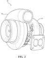
- a turbocharger 20 is shown schematically in FIG. 1 and in perspective view in FIG. 2 .
- the turbocharger 20 receives exhaust gas from an internal combustion engine and delivers compressed air to the internal combustion engine.
- the turbocharger 20 includes a turbine housing 22 defining a turbine housing interior 24 which receives exhaust gas from the internal combustion engine.
- the turbocharger 20 includes a turbine wheel 26 disposed in the turbine housing interior 24 for receiving the exhaust gas from the internal combustion engine. Specifically, the exhaust gas from the internal combustion engine is used to drive the turbine wheel 26.
- the turbocharger 20 additionally includes a compressor housing 28 defining a compressor housing interior 30.
- the compressor housing interior 30 receives and directs air to the internal combustion engine.
- the turbocharger 20 includes a compressor wheel 32 disposed in the compressor housing interior 30.
- the turbocharger 20 also includes a shaft 36 coupled to and rotatable by the turbine wheel 26, with the shaft 36 extending along a longitudinal axis A. Specifically, the turbine wheel 26 is driven by the exhaust gas from the internal combustion engine, which, in turn, rotates the shaft 36.
- the shaft 36 is also coupled to the compressor wheel 32.
- the compressor wheel 32 is rotatable by the shaft 36 for delivering compressed air to the internal combustion engine.
- the turbocharger 20 also includes a bearing housing assembly 34 including a bearing housing 38 extending along the longitudinal axis A, having an interior surface 40 defining a bearing housing interior 42, and configured to receive the shaft 36.
- the bearing housing assembly 34 also includes an anti-rotation assembly 44, as shown in FIGS. 4 and 5 .
- the anti-rotation assembly 44 includes a bearing assembly 46 disposed in the bearing housing interior 42 and configured to be disposed about the shaft 36 for supporting rotation of the shaft 36.
- the bearing assembly 46 is coupled to the shaft 36. In some embodiments, the bearing assembly 46 is directly engaged with the shaft 36.
- the anti-rotation assembly 44 further includes an anti-rotation spacer 48 disposed in the bearing housing interior 42 and configured to be disposed about the shaft 36.
- the anti-rotation spacer 48 may also be coupled to the bearing housing 38.
- the anti-rotation assembly 48 additionally includes a retaining ring 50 disposed about the shaft 36 and coupled to the anti-rotation spacer 48 to axially retain the anti-rotation spacer 48 in the bearing housing interior 42.
- the retaining ring 50 may apply a compressive force to the anti-rotation spacer 48 to maintain contact between the anti-rotation spacer 48 and the bearing assembly 46.
- the retaining ring 50 may have an interior diameter that is smaller than an exterior diameter of the bearing assembly 46 such that the bearing assembly 46 is axially retained in the bearing housing interior 42.
- the retaining ring 50 may also be directly engaged with the anti-rotation spacer 48.
- the anti-rotation spacer 48 has an engagement member 52 engageable with the retaining ring 50 and configured to limit rotation of the retaining ring 50 relative to the anti-rotation spacer 48.
- the anti-rotation spacer 48 has a spacer body portion 54 extending along the longitudinal axis A and the engagement member 52 may be configured to be engaged with the retaining ring 50 to limit rotation of the retaining ring 50 relative to the spacer body portion 54.
- the anti-rotation spacer 48 having the engagement member 52 rotationally fixes the anti-rotation spacer 48 relative to the retaining ring 50. Having the anti-rotation spacer 48 rotationally fixed to the retaining ring 50 assists in alignment of the bearing housing 38 during clocking of the turbocharger 20 in a vehicle. In one embodiment, the anti-rotation spacer 48 having the engagement member 52 engageable with the retaining ring 50 allows quicker alignment of the bearing housing 38 during clocking of the turbocharger 20 in the vehicle.
- the anti-rotation spacer 48 engages the retaining ring 50 to limit rotation of the retaining ring 50 relative to the anti-rotation spacer 48 as the bearing housing 38 is rotated relative the turbine housing 22 and/or to the compressor housing 28.
- the engagement member 52 has a protruding portion 58 extending toward and engageable with the retaining ring 50 to limit rotation of the retaining ring 50 relative to the anti-rotation spacer 48.
- the anti-rotation spacer 48 may have a spacer surface 56 perpendicular to the longitudinal axis A and facing the retaining ring 50, and the protruding portion 58 may extend from the spacer surface 56 axially with respect to the longitudinal axis A toward the retaining ring 50 to limit rotation of the retaining ring 50 relative to the anti-rotation spacer 48.
- the protruding portion 58 is engageable with the retaining ring 50. It is to be appreciated that the protruding portion 58 may extend from other portions of the anti-rotation spacer 48, such as radially away from the longitudinal axis A toward the retaining ring 50, while still limiting rotation of the retaining ring 50 relative to the anti-rotation spacer 48.
- the retaining ring 50 has a first end 60 and a second end 62 circumferentially spaced from the first end 60, with the first and second ends 60, 62 defining a gap 64 therebetween.
- the gap 64 has a width W defined between the first and second ends 60, 62.
- the protruding portion 58 may be engageable with at least one of the first and second ends 60, 62 of the retaining ring 50 to limit rotation of the retaining ring 50 relative to the anti-rotation spacer 48.
- first end 60 or the second end 62 may be engaged by the protruding portion 58 to limit rotation of the retaining ring 50 relative to the anti-rotation spacer 48. It is also to be appreciated that the both the first end 60 and the second end 62 may be engaged by the protruding portion 58 to limit rotation of the retaining ring 50 relative to the anti-rotation spacer 48.
- the protruding portion 58 of the engagement member 52 may be further defined as a first protruding portion 58, and the engagement member 52 may further have a second protruding portion 66 extending toward and engageable with the retaining ring 50.
- the first protruding portion 58 may be engageable with the first end 60 of the retaining ring 50 and the second protruding portion 66 may be engageable with the second end 62 of the retaining ring 50 to limit rotation of the retaining ring 50 relative to the anti-rotation spacer 48.
- the engagement member 52 has an engagement surface 68 and the retaining ring 50 has a retaining ring protruding portion 70 extending toward and engageable with the engagement surface 68 to limit rotation of the retaining ring 50 relative to the anti-rotation spacer 48.
- the retaining ring 50 may have a retaining surface 72 perpendicular to the longitudinal axis A and facing the anti-rotation spacer 48, and the retaining ring protruding portion 70 may extend from the retaining surface 72 axially with respect to the longitudinal axis A toward the engagement surface 68 of the anti-rotation spacer 48 to limit rotation of the retaining ring 50 relative to the anti-rotation spacer 48.
- the retaining ring protruding portion 70 is engageable with the engagement surface 68 of the anti-rotation spacer 48. It is to be appreciated that the retaining ring protruding portion 70 may extend from other portions of the retaining ring 50, such as radially away from the longitudinal axis A toward the engagement surface 68 of the anti-rotation spacer 48, while still limiting rotation of the retaining ring 50 relative to the anti-rotation spacer 48.
- the retaining ring protruding portion 70 may extend from at least one of the first and second ends 60, 62 of the retaining ring 50 and may be engageable with the engagement surface 68 of the anti-rotation spacer 48 to limit rotation of the retaining ring 50 relative to the anti-rotation spacer 48. It is to be appreciated that the retaining ring protruding portion 70 may extend from either the first end 60 or the second end 62, and toward the engagement surface 68 to engage the engagement surface 68 and limit rotation of the retaining ring 50 relative to the anti-rotation spacer 48.
- the retaining ring protruding portion 70 may extend from both the first end 60 and the second end 62 and toward the engagement surface 68 to engage the engagement surface 68 and limit rotation of the retaining ring 50 relative to the anti-rotation spacer 48.
- the anti-rotation spacer 48 may have a recessed portion 104 defined by the engagement surface 68, with the recessed portion 104 being configured to receive the retaining ring protruding portion 70.
- the recessed portion 104 of the anti-rotation spacer 48 may be defined completely through the anti-rotation spacer 48, such as a slot, partially defined through the anti-rotation spacer 48, such as an indentation, or any other geometry configured to receive the retaining ring protruding portion 70.
- the retaining ring protruding portion 70 may extend only partially into the recessed portion 104, or completely into the recessed portion 104 when the recessed portion 104 is defined partially through the anti-rotation spacer 48, or through the recessed portion 104 when the recessed portion 104 is defined completely through the anti-rotation spacer 48.
- the recessed portion 104 may be defined by all or a portion of the engagement surface 68, and the retaining ring 50 may be engageable with the engagement surface 68 to limit rotation of the retaining ring 50 relative to the anti-rotation spacer 48.
- the retaining ring protruding portion 70 may be engageable with the bearing housing 38 and may be configured to limit rotation of the retaining ring 50 relative to the bearing housing 38, as shown in FIGS. 14-16 .
- the retaining ring protruding portion 70 may extend through the recessed portion 104 and may be engageable with the bearing housing 38 to limit rotation of the retaining ring 50 relative to the bearing housing 38, as shown in FIGS. 13 and 16 .
- the interior surface 40, which the retaining ring protruding portion 70 may be engageable with may be cast with the bearing housing 38 to reduce manufacturing costs of the bearing housing 38.
- the interior surface 40 which the retaining ring protruding portion 70 may be engageable with may also be manufactured through other methods, such as through machining, while still being able to be engaged by the retaining ring protruding portion 70.
- the bearing housing 38 defines a lubricant sump 74 spaced radially from the bearing assembly 46 with respect to the longitudinal axis A, as shown in FIG. 6 .
- Lubricant is typically utilized to lubricate the bearing housing assembly 34 and the lubricant is drainable into the lubricant sump 74.
- the gap 64 defined between the first end 60 and the second end 62 of the retaining ring 50 may be alignable with the lubricant sump 74.
- the bearing housing assembly 34 further includes a lubricant deflector 76 disposed in the bearing housing interior 42 and coupled to the bearing housing 38.
- the gap 64 is alignable with the lubricant deflector 76 such that the lubricant deflector 76 is able to deflect the lubricant toward the lubricant sump 74.
- the lubricant deflector 76 may have a tongue 78 extending toward the lubricant sump 74.
- the tongue 78 may extend toward the gap 64 between the first and second ends 60, 62, as best shown in FIGS. 6 , 11 and 14 .
- the lubricant deflector 76 may direct lubricant toward the lubricant sump 74 without needing to be threaded into the bearing housing 38 or be manually aligned with the lubricant sump 74 during installation of the turbocharger 20 in the vehicle.
- the tongue 78 of the lubricant deflector 76 may be engageable with the engagement member 52, the first protruding portion 58, and/or the second protruding portion 66 to limit rotation of the lubricant deflector 76 relative to the anti-rotation spacer 48.
- the rotation of the lubricant deflector 76 relative to the bearing housing 38 may be indirectly limited through engagement of the lubricant deflector 76 to the anti-rotation spacer 48. This allows the anti-rotation spacer 48 and the lubricant deflector 76 to remain in rotational position relative to one another and relative to the bearing housing 38 during rotation and alignment of the bearing housing 38 when clocking the turbocharger 20 in the vehicle.
- the bearing assembly 46 may be any suitable bearing assembly for supporting rotation of the shaft 36.
- the bearing assembly 46 may be a rolling element bearing (REB) cartridge.
- the REB cartridge may have an inner race 82 disposed about the shaft 36, a plurality of rolling elements 84 radially spaced from the inner race 82 away from the longitudinal axis A, an intermediary race 86 disposed about the rolling elements 84, and an outer race 88 radially spaced from the rolling elements 84 away from the longitudinal axis A.
- the rolling elements 84 may be each in contact with an inner track defined in the inner race 82 and an outer track defined in the outer race 88 to allow rotation of inner race 82 relative to the outer race 88.
- the rolling elements 84 may be ball bearings.
- the outer race 88 may define a lubricant hole 90 through which lubricant may drain.
- the lubricant hole 90 may be alignable with the lubricant sump 74 to allow lubricant to drain through the lubricant hole 90 into the lubricant sump 74.
- the lubricant hole 90 may also be alignable with the lubricant deflector 76 such that the lubricant flows through the lubricant hole 90 and from the lubricant deflector 76 in the same direction. In a non-limiting example, the lubricant may flow through the lubricant hole 90 and from the lubricant deflector 76 toward the lubricant sump 74.
- the lubricant hole 90 may also be alignable with the tongue 78 of the lubricant deflector 76 such that the lubricant flows through the lubricant hole 90 and from the tongue 78 of the lubricant deflector 76 in the same direction.
- the lubricant may flow through the lubricant hole 90 and from the tongue 78 of the lubricant deflector 76 toward the lubricant sump 74. This prevents an undesired accumulation of lubricant in the bearing housing 38.
- the anti-rotation spacer 48 may have an inner surface 92 configured to face the shaft 36.
- the inner surface 92 may have at least one non-round section 94, as shown in FIGS. 3-5 , 9 , 10 and 12 .
- the at least one non-round section 94 may deviate from a circle with constant radius about the longitudinal axis A.
- the non-round section 94 may be depicted as a flat section. It is to be appreciated that the non-round section may be any other suitable configuration, such as polygonal or oval.
- the outer race 88 of the bearing assembly 46 may have an outer surface 96 facing the inner surface 92 of the anti-rotation spacer 48 and having at least one engaging section 98 engageable with the at least one non-round section 94 to limit rotation of the outer race 88 of the bearing assembly 46 relative to the anti-rotation spacer 48.
- the at least one engaging section 98 corresponds in configuration with the at least one non-round section 94.
- the at least one engaging section 98 may be flat, polygonal, or oval.
- the engagement member 52 of the anti-rotation spacer 48 may further be defined as a first engagement member 52, and the anti-rotation spacer 48 may have a second engagement member 100 engageable with the interior surface 40 of the bearing housing 38 to limit rotation of the anti-rotation spacer 48 relative to the bearing housing 38, as shown in FIGS. 4 , 5 , and 8-10 .
- the second engagement member 100 may have a bearing housing protruding portion 102 extending toward and engageable with the interior surface 40 of the bearing housing 38.
- the interior surface 40 which the second engagement member 100 is engageable with may be cast with the bearing housing 38 to reduce manufacturing costs of the bearing housing 38. It is to be appreciated, however, that the interior surface 40 which the second engagement member 100 is engageable with may also be manufactured through other methods, such as through machining, while still being able to be engaged by the second engagement member 100.
- both the first engagement member 52 and the second engagement member 100 limit rotation of the retaining ring 50 relative to the bearing housing 38.
- the first engagement member 52 limits rotation of the anti-rotation spacer 48 relative to the retaining ring 50 and the second engagement member 100 limits rotation of the anti-rotation spacer 48 relative to the bearing housing 38. Therefore, in embodiments where both the first engagement member 52 and the second engagement member 100 are present, the first engagement member 52 and the second engagement member 100 limit rotation of the retaining ring 50 relative to the bearing housing 38 indirectly through the anti-rotation spacer 48.
- this allows the gap 64 defined between the first and second ends 60, 62 of the retaining ring 50 to be aligned with the lubricant sump 74. This further allows the anti-rotation spacer 48 and the retaining ring 50 to remain in rotational position relative to one another and relative to the bearing housing 38 during rotation and alignment of the bearing housing 38 when clocking the turbocharger 20 in the vehicle.
- both the first engagement member 52 and the retaining ring protruding portion 70 limit rotation of the anti-rotation spacer 48 relative to the bearing housing 38.
- the first engagement member 52 limits rotation of the anti-rotation spacer 48 relative to the retaining ring 50
- the retaining ring protruding portion 70 limits rotation of the retaining ring 50 both relative to the anti-rotation spacer 48 through engagement of the engagement surface 68 and relative to the bearing housing 38 through engagement of the interior surface 40.
- the first engagement member 52 and the retaining ring protruding portion 70 limit rotation of the anti-rotation spacer 48 relative to the bearing housing 38 indirectly through the retaining ring 50.
- this allows the gap 64 defined between the first and second ends 60, 62 of the retaining ring 50 to be aligned with the lubricant sump 74.
- This further allows the anti-rotation spacer 48 and the retaining ring 50 to remain in rotational position relative to another and relative to the bearing housing 38 during rotation and alignment of the bearing housing 38 when clocking the turbocharger 20 in the vehicle.
- bearing housing assembly 34 is described above as being used in a turbocharger 20, it is to be appreciated that other uses exist for the bearing housing assembly 34, such as in turbo-machinery, compressor-machinery, or turbine-machinery.
- anti-rotation assembly 44 is described above as being used in a turbocharger 20, it is to be appreciated that other uses exist for the anti-rotation assembly 44, such as in turbo-machinery, compressor-machinery, or turbine-machinery.
- anti-rotation spacer 48 is described above as being used in a turbocharger 20, it is to be appreciated that other uses exist for the anti-rotation spacer 48, such as in turbo-machinery, compressor-machinery, or turbine machinery.
- turbocharger 20 and dimensions of the various components of the turbocharger 20 are merely illustrative and may not be drawn to scale.
- the invention has been described in an illustrative manner, and modifications and variations of the present invention are possible within the scope of the appended claims.
Landscapes
- Engineering & Computer Science (AREA)
- General Engineering & Computer Science (AREA)
- Mechanical Engineering (AREA)
- Chemical & Material Sciences (AREA)
- Combustion & Propulsion (AREA)
- Chemical Kinetics & Catalysis (AREA)
- General Chemical & Material Sciences (AREA)
- Supercharger (AREA)
- Mounting Of Bearings Or Others (AREA)
- Rolling Contact Bearings (AREA)
Description
- The present invention generally relates to a bearing housing assembly and, more specifically, to an anti-rotation assembly for use in the bearing housing assembly.
- Turbochargers receive exhaust gas from an internal combustion engine of a vehicle and deliver compressed air to the internal combustion engine. Turbochargers are used to increase power output of the internal combustion engine, lower fuel consumption of the internal combustion engine, and reduce emissions produced by the internal combustion engine. Delivery of compressed air to the internal combustion engine by the turbocharger allows the internal combustion engine to be smaller, yet able to develop the same or similar amount of horsepower as larger, naturally aspirated internal combustion engines. Having a smaller internal combustion engine for use in the vehicle reduces the mass and aerodynamic frontal area of the vehicle, which helps reduce fuel consumption of the internal combustion engine and improve fuel economy of the vehicle.
- Typical turbochargers include a turbine housing defining a turbine housing interior and a turbine wheel disposed in the turbine housing interior. Turbochargers further include a compressor housing coupled to the bearing housing and defining a compressor housing interior, and include a compressor wheel disposed in the compressor housing interior. Turbochargers also include a shaft disposed in the turbine housing interior and the compressor housing interior, with the shaft extending along the longitudinal axis and coupled to and rotatable with the turbine wheel and the compressor wheel. Specifically, the exhaust gas from the internal combustion engine, which would normally contain wasted energy, is used to drive the turbine wheel, which is used to drive the shaft and, in turn, the compressor wheel to deliver compressed air to the internal combustion engine.
- Turbochargers also include a bearing housing assembly including a bearing housing extending along a longitudinal axis, coupled to the turbine housing and to the compressor housing, and defining a bearing housing interior and a lubricant sump. Bearing housing assemblies in typical turbochargers also include a bearing assembly disposed in the bearing housing interior and disposed about the shaft for supporting rotation of the shaft. The bearing assembly typically rotates independently from the bearing housing. In other words, the bearing assembly and the bearing housing are not rotatably coupled to one another such that the bearing housing and the bearing housing assembly may rotate independently of one another.
- Bearing housing assemblies in typical turbochargers additionally include a retaining ring disposed about the shaft and coupled to the bearing housing to axially retain the bearing assembly in the bearing housing interior. Some turbochargers may include a lubricant deflector disposed in and coupled to the bearing housing to deflect lubricant toward the lubricant sump defined by the bearing housing.
-
DE 10 2012 206304 A1 discloses a bearing housing assembly according to the preamble of claim 1. This document relates to a charging device with a supporting shaft connecting a turbine wheel and a compressor wheel. The shaft is mounted in a bearing housing of the charging device via a roller bearing. The roller bearing has an outer sleeve via which it is in contact with the bearing housing. The bearing housing is closed off on the compressor side by a bearing housing cover. The outer sleeve and the bearing housing cover are fixed to one another in a rotationally fixed manner via a positive-locking connection. This reduces the number of parts and simplifies assembly. -
EP 3 144 497 A1 discloses an electric supercharger wherein the assemblability of a bearing holding structure is improved. An electric motor of an electric supercharger has a shaft. A second bearing supports the shaft rotatably. The second bearing comprises an outer ring and an inner ring rotatable with respect to each other. A second bearing sleeve supports the outer ring as a fixed ring. A key ring positions the outer ring with respect to the second bearing sleeve. A preloading spring energizes the key ring toward the outer ring or the second bearing sleeve. -
US 2014/0265685 A1 relates to a bearing assembly which cooperates with a bearing seat formed in a bearing housing. The assembly includes a bearing having an inner ring, an outer ring and a rolling element in engagement with the inner ring and the outer ring, and an anti-rotation device. The anti-rotation device engages the outer ring of the bearing and with the bearing housing to limit the rotation of the outer ring of the bearing within the bearing seat formed in the bearing housing. The anti-rotation device includes a first feature for engagement with the outer ring of the bearing and a second feature for engagement with the bearing housing. The first feature and the second feature limit the rotation of the outer ring of the bearing within the bearing seat formed in the bearing housing -
WO2016/079543A1 discloses an assembly, which comprises a first member, a second member and an anti-rotation device. The first member is provided with a bore and a groove on a surface of the bore. At least a portion of the second member is disposed within the bore in the first member and a recess is provided on a generally axially facing surface of the portion of the second member. The anti-rotation device comprises an arcuate resilient body comprising a radially inner portion and a radially outer portion, the radially outer portion being received within the groove, the radially inner portion abutting a surface of the portion of the second member. A first anti-rotation feature is provided on the radially outer portion for cooperation with a complimentary feature of the first member. A second anti-rotation feature is provided on the radially inner portion, extending away from the radially inner portion of the body in a generally axial direction and is received within the recess on the second member. -
US5207566A relates to a turbocharger bearing containing a sleeve which is floatingly disposed in a bore of a bearing case for radially mounting a shaft. To prevent rotation of the sleeve an element is disposed in the bearing case, which engages both a notch in the sleeve and a recess in the bearing case. This arrangement prevents high surface pressures between the element and the sleeve and between the element and the bearing case. The element is constructed as a retaining ring having a tongue and at least one boss. The tongue engages the recess in the bearing case. The boss is pointed toward the end face of the sleeve where its outside surface contacts at least one surface of the notch formed in the end face of the sleeve. - Turbochargers require clocking upon installation in the vehicle. During installation, the compressor housing and the turbine housing are rotationally fixed along the longitudinal axis relative to the vehicle. In contrast to the compressor housing and the turbine housing, the bearing housing requires rotation about the longitudinal axis to align the lubricant sump with the ground beneath the vehicle. This alignment is necessary to facilitate flow of lubricant through the turbocharger, as lubricant is only subject to gravitational forces and is not under pressure in turbochargers.
- The bearing assembly, the retaining ring, and the lubricant deflector of typical bearing housing assemblies do not rotate with the bearing housing during rotation and alignment of the bearing housing when clocking the turbocharger in the vehicle. The bearing assembly, the retaining ring, and the lubricant deflector, therefore, are unable remain in rotational position relative to one another and relative to the bearing housing during clocking of the turbocharger. In particular, the retaining ring and the lubricant deflector in turbochargers are unable to remain aligned with the lubricant sump during rotation and alignment of the bearing housing. Therefore, the retaining ring and the lubricant deflector are unable to direct lubricant toward the lubricant sump of the bearing housing, resulting in an undesired accumulation of lubricant in the bearing housing.
- As such, there remains a need to provide for an improved bearing housing assembly that rotationally fixes internal components of the bearing housing during rotation and alignment of the bearing housing when clocking the turbocharger in the vehicle.
- The present invention refers to a bearing housing assembly as defined in claim 1 and a turbocharger as defined in claim 14. The dependent claims define preferred embodiments of the bearing housing assembly and the turbocharger.
- Accordingly, the engagement member of the anti-rotation spacer rotationally fixes the anti-rotation spacer relative to the retaining ring, which allows quicker alignment of the bearing housing during clocking of the turbocharger in a vehicle.
- Other advantages of the present invention will be readily appreciated, as the same becomes better understood by reference to the following detailed description when considered in connection with the accompanying drawings wherein:
-
FIG. 1 is a schematic illustration of a turbocharger including a turbine housing defining a turbine housing interior, a turbine wheel disposed in the turbine housing interior, a compressor housing defining a compressor housing interior, a compressor wheel disposed in the compressor housing interior, and a bearing housing assembly including a bearing housing and a shaft; -
FIG. 2 is a perspective view of the turbocharger, with the bearing housing removed; -
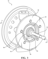
FIG. 3 is a perspective view of the bearing housing assembly including the bearing housing defining a bearing housing interior, the shaft disposed in the bearing housing interior, and an anti-rotation assembly, with the anti-rotation assembly including a bearing assembly disposed in the bearing housing interior, an anti-rotation spacer disposed in the bearing housing interior and which has a first engagement member comprising a protruding portion extending toward and engageable with the retaining ring to limit rotation of the retaining ring relative to the anti-rotation spacer, wherein the first engagement member comprising the protruding portion is not covered by the claimed invention, and a retaining ring coupled to the anti-rotation spacer; -
FIG. 4 is a perspective view of the anti-rotation assembly, wherein the anti-rotation spacer has the first engagement member comprising the protruding portion not covered by the claimed invention; -
FIG. 5 is an exploded view of the anti-rotation assembly, with the bearing assembly including an outer race, wherein the anti-rotation spacer has the first engagement member comprising the protruding portion not covered by the claimed invention; -
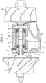
FIG. 6 is a cross-sectional view of the bearing housing assembly taken along line 6-6 ofFIG. 3 , with the bearing housing assembly including a lubricant deflector disposed about the shaft and coupled to the bearing housing; -
FIG. 7 is a perspective view of the bearing housing assembly, with the anti-rotation spacer having a second engagement member having a bearing housing protruding portion extending toward and engageable with the interior surface of the bearing housing, and wherein the anti-rotation spacer has the first engagement member comprising the protruding portion not covered by the claimed invention; -
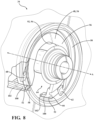
FIG. 8 is a perspective view of the bearing housing assembly, with the retaining ring and the anti-rotation spacer having the second engagement member shown partly in phantom, with the second engagement member having the bearing housing protruding portion extending toward and engageable with the interior surface of the bearing housing, and wherein the anti-rotation spacer has the first engagement member comprising the protruding portion not covered by the claimed invention; -
FIG. 9 is a front view of the bearing housing assembly, with the anti-rotation spacer having first and second ends, first and second protruding portions not covered by the claimed invention, and an inner surface having at least one non-round section, and with the bearing assembly having an outer race having an outer surface facing the inner surface of the anti-rotation spacer and having at least one engaging section engageable with the at least one non-round section, where the first and second ends of the retaining ring are spaced from the first and second protruding portions which is not covered by the claimed invention; -
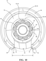
FIG. 10 is a front view of the bearing housing assembly, with the first and second ends of the retaining ring engaged with the first and second protruding portions which is not covered by the claimed invention; -
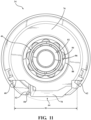
FIG. 11 is a front view of the bearing housing assembly having the lubricant deflector, with the first and second ends of the retaining ring defining a gap therebetween that is alignable with the lubricant sump and with the lubricant deflector, and with the lubricant deflector having a tongue that is alignable with the lubricant sump, and wherein the anti-rotation spacer has the first engagement member comprising the protruding portion not covered by the claimed invention; -
FIG. 12 is a front view of the claimed bearing housing assembly, with the engagement member of the anti-rotation spacer having an engagement surface, with the retaining ring having a first end and a second end defining a gap therebetween, with the retaining ring having a retaining ring protruding portion extending from at least one of the first end and the second end of the retaining ring and toward the engagement surface, and with the retaining ring protruding portion engageable with the engagement surface; -
FIG. 13 is a front view of the claimed bearing housing assembly, with the engagement member of the anti-rotation spacer having a recessed portion defined by the engagement surface, and with the retaining ring having the first end and the second end defining a gap therebetween, with the retaining ring having a retaining ring protruding portion extending from at least one of the first end and the second end of the retaining ring and toward the engagement surface defining the recessed portion; -
FIG. 14 is a cross-sectional view of the claimed bearing housing assembly taken along line 6-6 ofFIG. 3 , with the retaining ring having a retaining surface facing the anti-rotation spacer, and with the retaining ring protruding portion extending from the retaining surface toward the engagement surface of the anti-rotation spacer; -
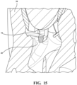
FIG. 15 is a perspective view of the claimed bearing housing assembly shown partly in cross-sectional view, with the retaining ring protruding portion engageable with the bearing housing; and -
FIG. 16 is a perspective view of the claimed bearing housing assembly, with the retaining ring protruding portion extending through the recessed portion of the anti-rotation spacer, and with the retaining ring protruding portion engaged with the bearing housing. - With reference to the figures, wherein like numerals indicate like parts throughout the several views, a
turbocharger 20 is shown schematically inFIG. 1 and in perspective view inFIG. 2 . Theturbocharger 20 receives exhaust gas from an internal combustion engine and delivers compressed air to the internal combustion engine. Theturbocharger 20 includes aturbine housing 22 defining aturbine housing interior 24 which receives exhaust gas from the internal combustion engine. Theturbocharger 20 includes aturbine wheel 26 disposed in theturbine housing interior 24 for receiving the exhaust gas from the internal combustion engine. Specifically, the exhaust gas from the internal combustion engine is used to drive theturbine wheel 26. Theturbocharger 20 additionally includes acompressor housing 28 defining acompressor housing interior 30. Thecompressor housing interior 30 receives and directs air to the internal combustion engine. Theturbocharger 20 includes acompressor wheel 32 disposed in thecompressor housing interior 30. - The
turbocharger 20 also includes ashaft 36 coupled to and rotatable by theturbine wheel 26, with theshaft 36 extending along a longitudinal axis A. Specifically, theturbine wheel 26 is driven by the exhaust gas from the internal combustion engine, which, in turn, rotates theshaft 36. Theshaft 36 is also coupled to thecompressor wheel 32. Thecompressor wheel 32 is rotatable by theshaft 36 for delivering compressed air to the internal combustion engine. - With reference to
FIGS. 3 ,6-15 , theturbocharger 20 also includes a bearinghousing assembly 34 including a bearinghousing 38 extending along the longitudinal axis A, having aninterior surface 40 defining a bearinghousing interior 42, and configured to receive theshaft 36. The bearinghousing assembly 34 also includes ananti-rotation assembly 44, as shown inFIGS. 4 and5 . Theanti-rotation assembly 44 includes a bearingassembly 46 disposed in the bearinghousing interior 42 and configured to be disposed about theshaft 36 for supporting rotation of theshaft 36. Typically, the bearingassembly 46 is coupled to theshaft 36. In some embodiments, the bearingassembly 46 is directly engaged with theshaft 36. Theanti-rotation assembly 44 further includes ananti-rotation spacer 48 disposed in the bearinghousing interior 42 and configured to be disposed about theshaft 36. Theanti-rotation spacer 48 may also be coupled to the bearinghousing 38. Theanti-rotation assembly 48 additionally includes a retainingring 50 disposed about theshaft 36 and coupled to theanti-rotation spacer 48 to axially retain theanti-rotation spacer 48 in the bearinghousing interior 42. The retainingring 50 may apply a compressive force to theanti-rotation spacer 48 to maintain contact between theanti-rotation spacer 48 and the bearingassembly 46. Additionally, the retainingring 50 may have an interior diameter that is smaller than an exterior diameter of the bearingassembly 46 such that the bearingassembly 46 is axially retained in the bearinghousing interior 42. The retainingring 50 may also be directly engaged with theanti-rotation spacer 48. Theanti-rotation spacer 48 has anengagement member 52 engageable with the retainingring 50 and configured to limit rotation of the retainingring 50 relative to theanti-rotation spacer 48. In one embodiment, theanti-rotation spacer 48 has a spacer body portion 54 extending along the longitudinal axis A and theengagement member 52 may be configured to be engaged with the retainingring 50 to limit rotation of the retainingring 50 relative to the spacer body portion 54. - The
anti-rotation spacer 48 having theengagement member 52 rotationally fixes theanti-rotation spacer 48 relative to the retainingring 50. Having theanti-rotation spacer 48 rotationally fixed to the retainingring 50 assists in alignment of the bearinghousing 38 during clocking of theturbocharger 20 in a vehicle. In one embodiment, theanti-rotation spacer 48 having theengagement member 52 engageable with the retainingring 50 allows quicker alignment of the bearinghousing 38 during clocking of theturbocharger 20 in the vehicle. Specifically, when the bearinghousing 38 is coupled to theturbine housing 22 and thecompressor housing 28 during rotation and alignment of the bearinghousing 38 and clocking of theturbocharger 20, theanti-rotation spacer 48 engages the retainingring 50 to limit rotation of the retainingring 50 relative to theanti-rotation spacer 48 as the bearinghousing 38 is rotated relative theturbine housing 22 and/or to thecompressor housing 28. - In one embodiment not covered by the claimed invention, as best shown in
FIGS. 3-5 , and9-11 , theengagement member 52 has a protrudingportion 58 extending toward and engageable with the retainingring 50 to limit rotation of the retainingring 50 relative to theanti-rotation spacer 48. Theanti-rotation spacer 48 may have aspacer surface 56 perpendicular to the longitudinal axis A and facing the retainingring 50, and the protrudingportion 58 may extend from thespacer surface 56 axially with respect to the longitudinal axis A toward the retainingring 50 to limit rotation of the retainingring 50 relative to theanti-rotation spacer 48. Specifically, to limit rotation of the retainingring 50 relative to theanti-rotation spacer 48, the protrudingportion 58 is engageable with the retainingring 50. It is to be appreciated that the protrudingportion 58 may extend from other portions of theanti-rotation spacer 48, such as radially away from the longitudinal axis A toward the retainingring 50, while still limiting rotation of the retainingring 50 relative to theanti-rotation spacer 48. - With reference to
FIGS. 4 ,5 , and8-12 , the retainingring 50 has afirst end 60 and asecond end 62 circumferentially spaced from thefirst end 60, with the first and second ends 60, 62 defining agap 64 therebetween. When present, thegap 64 has a width W defined between the first and second ends 60, 62. The protrudingportion 58 may be engageable with at least one of the first and second ends 60, 62 of the retainingring 50 to limit rotation of the retainingring 50 relative to theanti-rotation spacer 48. It is to be appreciated that either thefirst end 60 or thesecond end 62 may be engaged by the protrudingportion 58 to limit rotation of the retainingring 50 relative to theanti-rotation spacer 48. It is also to be appreciated that the both thefirst end 60 and thesecond end 62 may be engaged by the protrudingportion 58 to limit rotation of the retainingring 50 relative to theanti-rotation spacer 48. - In some embodiments, the protruding
portion 58 of theengagement member 52 may be further defined as a first protrudingportion 58, and theengagement member 52 may further have a second protrudingportion 66 extending toward and engageable with the retainingring 50. In such embodiments, the first protrudingportion 58 may be engageable with thefirst end 60 of the retainingring 50 and the second protrudingportion 66 may be engageable with thesecond end 62 of the retainingring 50 to limit rotation of the retainingring 50 relative to theanti-rotation spacer 48. - In another embodiment according to the claimed invention, as best shown in
FIGS. 12-16 , theengagement member 52 has anengagement surface 68 and the retainingring 50 has a retainingring protruding portion 70 extending toward and engageable with theengagement surface 68 to limit rotation of the retainingring 50 relative to theanti-rotation spacer 48. The retainingring 50 may have a retainingsurface 72 perpendicular to the longitudinal axis A and facing theanti-rotation spacer 48, and the retainingring protruding portion 70 may extend from the retainingsurface 72 axially with respect to the longitudinal axis A toward theengagement surface 68 of theanti-rotation spacer 48 to limit rotation of the retainingring 50 relative to theanti-rotation spacer 48. Specifically, to limit rotation of the retainingring 50 relative to theanti-rotation spacer 48, the retainingring protruding portion 70 is engageable with theengagement surface 68 of theanti-rotation spacer 48. It is to be appreciated that the retainingring protruding portion 70 may extend from other portions of the retainingring 50, such as radially away from the longitudinal axis A toward theengagement surface 68 of theanti-rotation spacer 48, while still limiting rotation of the retainingring 50 relative to theanti-rotation spacer 48. - With reference to
FIGS. 12-16 , the retainingring protruding portion 70 may extend from at least one of the first and second ends 60, 62 of the retainingring 50 and may be engageable with theengagement surface 68 of theanti-rotation spacer 48 to limit rotation of the retainingring 50 relative to theanti-rotation spacer 48. It is to be appreciated that the retainingring protruding portion 70 may extend from either thefirst end 60 or thesecond end 62, and toward theengagement surface 68 to engage theengagement surface 68 and limit rotation of the retainingring 50 relative to theanti-rotation spacer 48. It is also to be appreciated that the retainingring protruding portion 70 may extend from both thefirst end 60 and thesecond end 62 and toward theengagement surface 68 to engage theengagement surface 68 and limit rotation of the retainingring 50 relative to theanti-rotation spacer 48. - With reference to
FIGS. 13 and16 , theanti-rotation spacer 48 may have a recessedportion 104 defined by theengagement surface 68, with the recessedportion 104 being configured to receive the retainingring protruding portion 70. The recessedportion 104 of theanti-rotation spacer 48 may be defined completely through theanti-rotation spacer 48, such as a slot, partially defined through theanti-rotation spacer 48, such as an indentation, or any other geometry configured to receive the retainingring protruding portion 70. The retainingring protruding portion 70 may extend only partially into the recessedportion 104, or completely into the recessedportion 104 when the recessedportion 104 is defined partially through theanti-rotation spacer 48, or through the recessedportion 104 when the recessedportion 104 is defined completely through theanti-rotation spacer 48. The recessedportion 104 may be defined by all or a portion of theengagement surface 68, and the retainingring 50 may be engageable with theengagement surface 68 to limit rotation of the retainingring 50 relative to theanti-rotation spacer 48. - In some embodiments, the retaining
ring protruding portion 70 may be engageable with the bearinghousing 38 and may be configured to limit rotation of the retainingring 50 relative to the bearinghousing 38, as shown inFIGS. 14-16 . In one embodiment, the retainingring protruding portion 70 may extend through the recessedportion 104 and may be engageable with the bearinghousing 38 to limit rotation of the retainingring 50 relative to the bearinghousing 38, as shown inFIGS. 13 and16 . Theinterior surface 40, which the retainingring protruding portion 70 may be engageable with, may be cast with the bearinghousing 38 to reduce manufacturing costs of the bearinghousing 38. It is to be appreciated, however, that theinterior surface 40 which the retainingring protruding portion 70 may be engageable with may also be manufactured through other methods, such as through machining, while still being able to be engaged by the retainingring protruding portion 70. - The bearing
housing 38 defines alubricant sump 74 spaced radially from the bearingassembly 46 with respect to the longitudinal axis A, as shown inFIG. 6 . Lubricant is typically utilized to lubricate the bearinghousing assembly 34 and the lubricant is drainable into thelubricant sump 74. When present, thegap 64 defined between thefirst end 60 and thesecond end 62 of the retainingring 50 may be alignable with thelubricant sump 74. The bearinghousing assembly 34 further includes alubricant deflector 76 disposed in the bearinghousing interior 42 and coupled to the bearinghousing 38. Thegap 64 is alignable with thelubricant deflector 76 such that thelubricant deflector 76 is able to deflect the lubricant toward thelubricant sump 74. Thelubricant deflector 76 may have atongue 78 extending toward thelubricant sump 74. Thetongue 78 may extend toward thegap 64 between the first and second ends 60, 62, as best shown inFIGS. 6 ,11 and14 . - Another advantage of the bearing
housing assembly 34 is that thelubricant deflector 76 may direct lubricant toward thelubricant sump 74 without needing to be threaded into the bearinghousing 38 or be manually aligned with thelubricant sump 74 during installation of theturbocharger 20 in the vehicle. Specifically, thetongue 78 of thelubricant deflector 76 may be engageable with theengagement member 52, the first protrudingportion 58, and/or the second protrudingportion 66 to limit rotation of thelubricant deflector 76 relative to theanti-rotation spacer 48. In this way, the rotation of thelubricant deflector 76 relative to the bearinghousing 38 may be indirectly limited through engagement of thelubricant deflector 76 to theanti-rotation spacer 48. This allows theanti-rotation spacer 48 and thelubricant deflector 76 to remain in rotational position relative to one another and relative to the bearinghousing 38 during rotation and alignment of the bearinghousing 38 when clocking theturbocharger 20 in the vehicle. - The bearing
assembly 46 may be any suitable bearing assembly for supporting rotation of theshaft 36. In one embodiment, the bearingassembly 46 may be a rolling element bearing (REB) cartridge. In such embodiments, as best shown inFIGS. 6 and9-14 , the REB cartridge may have aninner race 82 disposed about theshaft 36, a plurality of rollingelements 84 radially spaced from theinner race 82 away from the longitudinal axis A, anintermediary race 86 disposed about the rollingelements 84, and anouter race 88 radially spaced from the rollingelements 84 away from the longitudinal axis A. The rollingelements 84 may be each in contact with an inner track defined in theinner race 82 and an outer track defined in theouter race 88 to allow rotation ofinner race 82 relative to theouter race 88. The rollingelements 84 may be ball bearings. - The
outer race 88 may define alubricant hole 90 through which lubricant may drain. Thelubricant hole 90 may be alignable with thelubricant sump 74 to allow lubricant to drain through thelubricant hole 90 into thelubricant sump 74. Thelubricant hole 90 may also be alignable with thelubricant deflector 76 such that the lubricant flows through thelubricant hole 90 and from thelubricant deflector 76 in the same direction. In a non-limiting example, the lubricant may flow through thelubricant hole 90 and from thelubricant deflector 76 toward thelubricant sump 74. Thelubricant hole 90 may also be alignable with thetongue 78 of thelubricant deflector 76 such that the lubricant flows through thelubricant hole 90 and from thetongue 78 of thelubricant deflector 76 in the same direction. In a non-limiting example, the lubricant may flow through thelubricant hole 90 and from thetongue 78 of thelubricant deflector 76 toward thelubricant sump 74. This prevents an undesired accumulation of lubricant in the bearinghousing 38. - In another embodiment, the
anti-rotation spacer 48 may have an inner surface 92 configured to face theshaft 36. The inner surface 92 may have at least onenon-round section 94, as shown inFIGS. 3-5 ,9 ,10 and12 . In such embodiments, the at least onenon-round section 94 may deviate from a circle with constant radius about the longitudinal axis A. Thenon-round section 94 may be depicted as a flat section. It is to be appreciated that the non-round section may be any other suitable configuration, such as polygonal or oval. Theouter race 88 of the bearingassembly 46 may have an outer surface 96 facing the inner surface 92 of theanti-rotation spacer 48 and having at least one engagingsection 98 engageable with the at least onenon-round section 94 to limit rotation of theouter race 88 of the bearingassembly 46 relative to theanti-rotation spacer 48. Specifically, the at least one engagingsection 98 corresponds in configuration with the at least onenon-round section 94. By way of example, the at least one engagingsection 98 may be flat, polygonal, or oval. - In another embodiment, the
engagement member 52 of theanti-rotation spacer 48 may further be defined as afirst engagement member 52, and theanti-rotation spacer 48 may have asecond engagement member 100 engageable with theinterior surface 40 of the bearinghousing 38 to limit rotation of theanti-rotation spacer 48 relative to the bearinghousing 38, as shown inFIGS. 4 ,5 , and8-10 . Thesecond engagement member 100 may have a bearinghousing protruding portion 102 extending toward and engageable with theinterior surface 40 of the bearinghousing 38. Theinterior surface 40 which thesecond engagement member 100 is engageable with may be cast with the bearinghousing 38 to reduce manufacturing costs of the bearinghousing 38. It is to be appreciated, however, that theinterior surface 40 which thesecond engagement member 100 is engageable with may also be manufactured through other methods, such as through machining, while still being able to be engaged by thesecond engagement member 100. - In embodiments where both the
first engagement member 52 and thesecond engagement member 100 are present, both thefirst engagement member 52 and thesecond engagement member 100 limit rotation of the retainingring 50 relative to the bearinghousing 38. Specifically, thefirst engagement member 52 limits rotation of theanti-rotation spacer 48 relative to the retainingring 50 and thesecond engagement member 100 limits rotation of theanti-rotation spacer 48 relative to the bearinghousing 38. Therefore, in embodiments where both thefirst engagement member 52 and thesecond engagement member 100 are present, thefirst engagement member 52 and thesecond engagement member 100 limit rotation of the retainingring 50 relative to the bearinghousing 38 indirectly through theanti-rotation spacer 48. In particular, this allows thegap 64 defined between the first and second ends 60, 62 of the retainingring 50 to be aligned with thelubricant sump 74. This further allows theanti-rotation spacer 48 and the retainingring 50 to remain in rotational position relative to one another and relative to the bearinghousing 38 during rotation and alignment of the bearinghousing 38 when clocking theturbocharger 20 in the vehicle. - In embodiments where both the
first engagement member 52 and the retainingring protruding portion 70 are present, both thefirst engagement member 52 and the retainingring protruding portion 70 limit rotation of theanti-rotation spacer 48 relative to the bearinghousing 38. Specifically, thefirst engagement member 52 limits rotation of theanti-rotation spacer 48 relative to the retainingring 50 and the retainingring protruding portion 70 limits rotation of the retainingring 50 both relative to theanti-rotation spacer 48 through engagement of theengagement surface 68 and relative to the bearinghousing 38 through engagement of theinterior surface 40. Therefore, in embodiments where both thefirst engagement member 52 and the retainingring protruding portion 70 are present, thefirst engagement member 52 and the retainingring protruding portion 70 limit rotation of theanti-rotation spacer 48 relative to the bearinghousing 38 indirectly through the retainingring 50. In particular, this allows thegap 64 defined between the first and second ends 60, 62 of the retainingring 50 to be aligned with thelubricant sump 74. This further allows theanti-rotation spacer 48 and the retainingring 50 to remain in rotational position relative to another and relative to the bearinghousing 38 during rotation and alignment of the bearinghousing 38 when clocking theturbocharger 20 in the vehicle. - Although the bearing
housing assembly 34 is described above as being used in aturbocharger 20, it is to be appreciated that other uses exist for the bearinghousing assembly 34, such as in turbo-machinery, compressor-machinery, or turbine-machinery. Similarly, although theanti-rotation assembly 44 is described above as being used in aturbocharger 20, it is to be appreciated that other uses exist for theanti-rotation assembly 44, such as in turbo-machinery, compressor-machinery, or turbine-machinery. Similarly to the bearinghousing assembly 34 and theanti-rotation assembly 44, although theanti-rotation spacer 48 is described above as being used in aturbocharger 20, it is to be appreciated that other uses exist for theanti-rotation spacer 48, such as in turbo-machinery, compressor-machinery, or turbine machinery. - It is to be appreciated that various components of the
turbocharger 20 and dimensions of the various components of theturbocharger 20 are merely illustrative and may not be drawn to scale. The invention has been described in an illustrative manner, and modifications and variations of the present invention are possible within the scope of the appended claims.
Claims (15)
- A bearing housing assembly (34) comprising:a bearing housing (38) extending along a longitudinal axis (A), with said bearing housing (38) having an interior surface (40) defining a bearing housing interior (42) configured to receive a shaft (36); andan anti-rotation assembly (44) comprising:a bearing assembly (46) extending along a longitudinal axis (A), and configured to be disposed in said bearing housing interior (42) and configured to be disposed about said shaft (36), said bearing assembly (46) being configured to support rotation of saidshaft (36), and wherein said bearing housing (38) defines a lubricant sump (74) spaced radially from said bearing assembly (46) with respect to said longitudinal axis (A) into which a lubricant of said bearing assembly (46) is drainable;an anti-rotation spacer (48) disposed about said longitudinal axis (A), and configured to be disposed in said bearing housing interior (42) and configured to be disposed about said shaft (36); anda retaining ring (50) disposed about said longitudinal axis (A), configured to be disposed about said shaft (36) and coupled to said anti-rotation spacer (48) to axially retain said anti-rotation spacer (48) in said bearing housing interior (42);wherein said anti-rotation spacer (48) has an engagement member (52) engageable with said retaining ring (50) and configured to limit rotation of said retaining ring (50) relative to said anti-rotation spacer (48);wherein said engagement member (52) has an engagement surface (68), and wherein said retaining ring (50) has a retaining ring protruding portion (70) extending toward and engageable with said engagement surface (68) to limit rotation of said retaining ring (50) relative to said anti-rotation spacer (48);characterized in that said retaining ring (50) has a first end (60) and a second end (62) circumferentially spaced from said first end (60), wherein said first and second ends (60, 62) defining a gap (64) therebetween, and wherein said gap (64) defined between said first end (60) and said second end (62) of said retaining ring (50) is alignable with said lubricant sump (74), andin that a lubricant deflector (76) is disposed in said bearing housing (38) and coupled to said bearing housing (38), wherein said gap (64) is alignable with said lubricant deflector (76) such that said lubricant deflector (76) is able to deflect the lubricant into said lubricant sump (74).
- The bearing housing assembly as set forth in claim 1, wherein said anti-rotation spacer (48) has an inner surface (92) configured to face said shaft (36), with said inner surface (92) having at least one non-round section (94), and wherein said bearing assembly (46) comprises an outer race (88) disposed about said longitudinal axis (A) and having an outer surface (96) facing said inner surface (92) of said anti-rotation spacer (48), with said outer surface (96) having at least one engaging section (98) engageable with said at least one non-round section (94) to limit rotation of said outer race (88) of said bearing assembly (46) relative to said anti-rotation spacer (48).
- The bearing housing assembly as set forth in claim 1 or claim 2, wherein said engagement member (52) is further defined as a first engagement member (52), and wherein said anti-rotation spacer (48) has a second engagement member (100) engageable with said interior surface (40) of said bearing housing (38) to limit rotation of said anti-rotation spacer (48) relative to said bearing housing (38).
- The bearing housing assembly as set forth in claim 3, wherein said second engagement member (100) has a bearing housing protruding portion (102) extending toward and engageable with said interior surface (40) of said bearing housing (38).
- The bearing housing assembly as set forth in any one of claims 1-4, wherein said retaining ring (50) has a retaining surface (72) perpendicular to said longitudinal axis (A) and facing said anti-rotation spacer (48), and wherein said retaining ring protruding portion (70) extends from said retaining surface (72) axially with respect to said longitudinal axis (A) toward said engagement surface (68) of said anti-rotation spacer (48) to limit rotation of said retaining ring (50) relative to said anti-rotation spacer (48).
- The bearing housing assembly as set forth in any one of claims 1, 2 or 5, wherein said retaining ring protruding portion (70) extends from at least one of said first and said second ends (60, 62) of said retaining ring (50) and is engageable with said engagement surface (68) of said anti-rotation spacer (48) to limit rotation of said retaining ring (50) relative to said anti-rotation spacer (48).
- The bearing housing assembly as set forth in any one of claims 1, 2, 5 or 6, wherein said retaining ring protruding portion (70) is engageable with said bearing housing (38) and configured to limit rotation of said retaining ring (50) relative to said bearing housing (38).
- The bearing housing assembly as set forth in any one of claims 1, 2 or 5-7, wherein said lubricant deflector (76) has a tongue (78) extending toward said lubricant sump (74).
- The bearing housing assembly as set forth in claim 8, wherein said tongue (78) of said lubricant deflector (76) extends toward said gap (64) defined between said first end (60) and said second end (62) of said retaining ring (50).
- The bearing housing assembly as set forth in claim 8 or claim 9, wherein said tongue (78) of said lubricant deflector (76) is engageable with said engagement member (52) of said anti-rotation spacer (48).
- The bearing housing assembly as set forth in any one of claims 8-10, wherein said bearing assembly (46) comprises an outer race (88) defining a lubricant hole (90) through which the lubricant is drainable, wherein said lubricant hole (90) is alignable with said tongue (78) of said lubricant deflector (76) such that the lubricant flows through said lubricant hole (90) and from said tongue (78) in the same direction.
- The bearing housing assembly as set forth in any one of claims 1, 2 or 5-11, wherein said lubricant deflector (76) is not threaded into said bearing housing (38).
- The bearing housing assembly as set forth in any one of claims 1, 2 or 5-12, wherein said retaining ring (50) is configured to apply a compressive force to said anti-rotation spacer (48) to maintain contact between said anti-rotation spacer (48) and said bearing assembly (46).
- A turbocharger (20) comprising:a turbine housing (22) defining a turbine housing interior (24);a turbine wheel (26) disposed in said turbine housing interior (24);a compressor housing (28) defining a compressor housing interior (30);a compressor wheel (32) disposed in said compressor housing interior (30);a shaft (36) disposed in said turbine housing interior (24) and said compressor housing interior (30), with said shaft (36) extending along a longitudinal axis (A) and coupled to and rotatable with said turbine wheel (26) and said compressor wheel (32), andsaid bearing housing assembly (34) as set forth in any one of claims 1 to 13, wherein said bearing housing interior (42) receives said shaft (36), said bearing assembly (46) is disposed about said shaft (36) and supports rotation of said shaft (36), said anti-rotation spacer (48) is disposed about said shaft (36), and said retaining ring (50) is disposed about said shaft (36).
- The turbocharger as set forth in claim 14, wherein:said anti-rotation spacer (48) has a second engagement member (100) engageable with said bearing housing (38) and configured to limit rotation of said anti-rotation spacer (48) relative to said bearing housing (38); andsaid anti-rotation spacer (48) has an inner surface (92) facing said shaft (36), with said inner surface (92) having at least one non-round section (94), wherein said bearing assembly (46) comprises an outer race (88) disposed about said longitudinal axis (A) and having an outer surface (96) facing said inner surface (92) of said anti-rotation spacer (48), with said outer surface (96) having at least one engaging section (98) engageable with said at least one non-round section (94) to limit rotation of said outer race (88) of said bearing assembly (46) relative to said anti-rotation spacer (48).
Applications Claiming Priority (1)
| Application Number | Priority Date | Filing Date | Title |
|---|---|---|---|
| US16/002,338 US11067131B2 (en) | 2018-06-07 | 2018-06-07 | Anti-rotation assembly and bearing housing assembly including the same |
Publications (2)
| Publication Number | Publication Date |
|---|---|
| EP3578840A1 EP3578840A1 (en) | 2019-12-11 |
| EP3578840B1 true EP3578840B1 (en) | 2023-08-02 |
Family
ID=66776104
Family Applications (1)
| Application Number | Title | Priority Date | Filing Date |
|---|---|---|---|
| EP19178546.8A Active EP3578840B1 (en) | 2018-06-07 | 2019-06-05 | Anti-rotation assembly and bearing housing assembly including the same |
Country Status (5)
| Country | Link |
|---|---|
| US (1) | US11067131B2 (en) |
| EP (1) | EP3578840B1 (en) |
| JP (1) | JP2019210936A (en) |
| KR (1) | KR20190139145A (en) |
| CN (2) | CN210509303U (en) |
Families Citing this family (4)
| Publication number | Priority date | Publication date | Assignee | Title |
|---|---|---|---|---|
| US11067131B2 (en) * | 2018-06-07 | 2021-07-20 | Borg Warner Inc. | Anti-rotation assembly and bearing housing assembly including the same |
| DE102020201186A1 (en) | 2020-01-31 | 2021-08-05 | Minebea Mitsumi Inc. | Fixing device for a rolling bearing ring, rolling bearing and exhaust gas turbine |
| US11846294B1 (en) | 2022-05-24 | 2023-12-19 | Borgwarner Inc. | Bearing housing assembly for a turbocharger |
| US20250347368A1 (en) * | 2024-05-13 | 2025-11-13 | Pratt & Whitney Canada Corp. | Non rotating spacer for gas turbine engine |
Citations (1)
| Publication number | Priority date | Publication date | Assignee | Title |
|---|---|---|---|---|
| US5207566A (en) * | 1990-01-30 | 1993-05-04 | Aktiengesellschaft Kuehnle, Kopp & Kausch | Exhaust gas turbocharger bearing |
Family Cites Families (34)
| Publication number | Priority date | Publication date | Assignee | Title |
|---|---|---|---|---|
| US2897022A (en) * | 1957-09-05 | 1959-07-28 | Torrington Co | Mounting for roller bearings |
| US3985458A (en) * | 1972-04-28 | 1976-10-12 | Roberts Industries, Inc. | Locking device |
| US4522515A (en) * | 1983-09-27 | 1985-06-11 | Koyo Seiko Company Limited | Mounting device for antifriction bearing |
| JPS60116920A (en) * | 1983-11-30 | 1985-06-24 | Hitachi Ltd | Thrust bearing holding in rotary fluid machine |
| DE3531313C3 (en) * | 1984-09-03 | 1995-04-20 | Ishikawajima Harima Heavy Ind | Bearing device in a turbocharger |
| DE3712444A1 (en) * | 1987-04-11 | 1988-10-27 | Kuehnle Kopp Kausch Ag | EXHAUST TURBOCHARGER STORAGE |
| EP1174629A1 (en) * | 2000-06-30 | 2002-01-23 | Techspace Aero S.A. | Sealing device of a squeeze film damper incorporated in a rolling element bearing |
| US6409390B1 (en) * | 2000-10-31 | 2002-06-25 | Itt Manufacturing Enterprises, Inc. | Compact, precision duplex bearing mount for high vibration environments |
| US7214037B2 (en) * | 2004-06-28 | 2007-05-08 | Honeywell International, Inc. | Retention of ball bearing cartridge for turbomachinery |
| DE112010003093T5 (en) | 2009-05-07 | 2012-10-31 | Borgwarner Inc. | SLIDING SLIP PROCEDURE FOR VERDREBSICHERUNG AND SCHREIBBEGRENZUNG A GROUND ELEMENT STOCK CARTRIDGE |
| US8496452B2 (en) * | 2009-08-26 | 2013-07-30 | Honeywell International Inc. | Bearing spacer and housing |
| US8961128B2 (en) * | 2009-08-26 | 2015-02-24 | Honeywell International Inc. | Bearing spacer and housing |
| IT1395716B1 (en) * | 2009-09-22 | 2012-10-19 | Nuovo Pignone Spa | BEARING, FIXING MECHANISM AND METHOD TO FIX AT LEAST ONE SHOE. |
| CN103180570B (en) | 2010-10-28 | 2015-09-30 | 博格华纳公司 | There is the rolling element bearing sleeve of end thrust damping and anti-rotating assembly |
| US8764384B2 (en) | 2010-12-16 | 2014-07-01 | Honeywell International Inc. | Joint for housing alignment |
| JP5904748B2 (en) * | 2011-10-14 | 2016-04-20 | キヤノン株式会社 | Image heating device |
| DE102012206304A1 (en) | 2012-04-17 | 2013-10-17 | Bosch Mahle Turbo Systems Gmbh & Co. Kg | Charging device e.g. exhaust gas turbocharger of internal combustion engine of motor car, has outer sleeve and bearing cover that are rotatably fixed to one another through connector |
| CN104271921B (en) * | 2012-05-15 | 2017-05-17 | 霍尼韦尔国际公司 | Turbocharger with journal bearing |
| KR102035673B1 (en) | 2012-06-25 | 2019-10-23 | 보르그워너 인코퍼레이티드 | Exhaust-gas turbocharger |
| RU2015107165A (en) | 2012-08-17 | 2016-09-27 | Боргварнер Инк. | TURBOCHARGER SPEED SENSOR INSERT WITH POSITION OF BEARING SPACING BUSH |
| US9281725B2 (en) | 2013-03-13 | 2016-03-08 | Regal Beloit America, Inc. | Electric machine and method of manufacturing the same |
| GB201307674D0 (en) | 2013-04-29 | 2013-06-12 | Cummins Ltd | Turbomachine With Axial Stop Member |
| US9963998B2 (en) | 2013-06-18 | 2018-05-08 | Honeywell International Inc. | Assembly with bearings and spacer |
| JP2015218591A (en) | 2014-05-14 | 2015-12-07 | 株式会社豊田自動織機 | Electric turbocharger |
| GB201420626D0 (en) * | 2014-11-20 | 2015-01-07 | Cummins Ltd | Bearing unit anti-rotation device |
| CN107208544B (en) * | 2015-02-09 | 2020-03-03 | 三菱重工发动机和增压器株式会社 | supercharger |
| US9181955B1 (en) * | 2015-02-18 | 2015-11-10 | Borgwarner Inc. | Method for reducing aero clearances with a ball bearing turbocharger |
| US9752536B2 (en) | 2015-03-09 | 2017-09-05 | Caterpillar Inc. | Turbocharger and method |
| US9745992B2 (en) | 2015-08-30 | 2017-08-29 | Honeywell International Inc. | Turbocharger bearing damper assembly |
| DE102015220384A1 (en) * | 2015-10-20 | 2017-04-20 | Schaeffler Technologies AG & Co. KG | Circlip for high speed applications with two axially locking faces and bearing system therewith |
| CN108368777A (en) | 2015-12-10 | 2018-08-03 | 舍弗勒技术股份两合公司 | Bearing arrangement with anti-rotation element for turbocharger |
| US20170191377A1 (en) | 2016-01-04 | 2017-07-06 | Borgwarner Inc. | Damper and methods of making and using the same |
| DE102016209149B4 (en) | 2016-01-22 | 2025-05-08 | Minebea Mitsumi Inc. | Bearing unit for an exhaust gas turbocharger or an exhaust gas turbine and bearing with such a bearing unit |
| US11067131B2 (en) * | 2018-06-07 | 2021-07-20 | Borg Warner Inc. | Anti-rotation assembly and bearing housing assembly including the same |
-
2018
- 2018-06-07 US US16/002,338 patent/US11067131B2/en active Active
-
2019
- 2019-06-04 JP JP2019104252A patent/JP2019210936A/en active Pending
- 2019-06-04 KR KR1020190065881A patent/KR20190139145A/en not_active Withdrawn
- 2019-06-05 EP EP19178546.8A patent/EP3578840B1/en active Active
- 2019-06-06 CN CN201920850371.7U patent/CN210509303U/en active Active
- 2019-06-06 CN CN201910490625.3A patent/CN110578563B/en active Active
Patent Citations (1)
| Publication number | Priority date | Publication date | Assignee | Title |
|---|---|---|---|---|
| US5207566A (en) * | 1990-01-30 | 1993-05-04 | Aktiengesellschaft Kuehnle, Kopp & Kausch | Exhaust gas turbocharger bearing |
Also Published As
| Publication number | Publication date |
|---|---|
| CN110578563A (en) | 2019-12-17 |
| CN210509303U (en) | 2020-05-12 |
| US20190376560A1 (en) | 2019-12-12 |
| KR20190139145A (en) | 2019-12-17 |
| US11067131B2 (en) | 2021-07-20 |
| JP2019210936A (en) | 2019-12-12 |
| EP3578840A1 (en) | 2019-12-11 |
| CN110578563B (en) | 2023-08-29 |
Similar Documents
| Publication | Publication Date | Title |
|---|---|---|
| EP3578840B1 (en) | Anti-rotation assembly and bearing housing assembly including the same | |
| US8740465B2 (en) | Bearing system | |
| EP1972759B1 (en) | Stepped outer diameter semi-floating bearing | |
| CN102395770B (en) | Anti-rotation method for a rolling element bearing cartridge | |
| EP3511577B1 (en) | Bearing assembly with damping features | |
| CN100432459C (en) | Bearing device of turbocharger | |
| EP1896696B1 (en) | Turbocharger bearing and associated components | |
| US7832938B2 (en) | Floating bearing cartridge for a turbocharger shaft | |
| US4676667A (en) | Variable preload shaft bearing for turbocharger | |
| KR101838169B1 (en) | Sliding clip method for anti-rotation and thrust constraint of a rolling element bearing cartridge | |
| KR20120006556A (en) | Spring clip method for anti-rotation and thrust restraint of rolling element bearing cartridge | |
| US8757888B2 (en) | Shaft/bearing arrangement | |
| US9234542B2 (en) | Bearing system | |
| EP2208903A2 (en) | Bearing and retention mechanisms | |
| EP1837537A2 (en) | Split roller bearing device | |
| US20180180094A1 (en) | Method For Mounting A Rolling Bearing Unit On The Rotor Of A Turbocharger | |
| JP2010138753A (en) | Bearing device for supercharger | |
| CN110249144B (en) | Sliding bearing with hydraulic axial stop | |
| EP1992814B1 (en) | Balanced bearing assembly | |
| CN214330710U (en) | Bearing assembly and turbocharger comprising same | |
| US11280218B2 (en) | Bearing housing assembly and turbocharger including the same | |
| CN218581692U (en) | Turbocharger comprising a bearing assembly | |
| US11846294B1 (en) | Bearing housing assembly for a turbocharger | |
| CN209483441U (en) | Bearing unit for turbocharger rotor and the supercharging device for internal combustion engine | |
| US20160076592A1 (en) | Supercharger bearing with grease reservoir |
Legal Events
| Date | Code | Title | Description |
|---|---|---|---|
| PUAI | Public reference made under article 153(3) epc to a published international application that has entered the european phase |
Free format text: ORIGINAL CODE: 0009012 |
|
| STAA | Information on the status of an ep patent application or granted ep patent |
Free format text: STATUS: REQUEST FOR EXAMINATION WAS MADE |
|
| 17P | Request for examination filed |
Effective date: 20190605 |
|
| AK | Designated contracting states |
Kind code of ref document: A1 Designated state(s): AL AT BE BG CH CY CZ DE DK EE ES FI FR GB GR HR HU IE IS IT LI LT LU LV MC MK MT NL NO PL PT RO RS SE SI SK SM TR |
|
| AX | Request for extension of the european patent |
Extension state: BA ME |
|
| STAA | Information on the status of an ep patent application or granted ep patent |
Free format text: STATUS: EXAMINATION IS IN PROGRESS |
|
| 17Q | First examination report despatched |
Effective date: 20210319 |
|
| REG | Reference to a national code |
Ref country code: DE Free format text: PREVIOUS MAIN CLASS: F16C0033660000 Ref country code: DE Ref legal event code: R079 Ref document number: 602019033879 Country of ref document: DE Free format text: PREVIOUS MAIN CLASS: F16C0033660000 Ipc: F01D0025240000 |
|
| GRAP | Despatch of communication of intention to grant a patent |
Free format text: ORIGINAL CODE: EPIDOSNIGR1 |
|
| STAA | Information on the status of an ep patent application or granted ep patent |
Free format text: STATUS: GRANT OF PATENT IS INTENDED |
|
| RIC1 | Information provided on ipc code assigned before grant |
Ipc: F01M 11/02 20060101ALI20230207BHEP Ipc: F16C 35/04 20060101ALI20230207BHEP Ipc: F16C 19/18 20060101ALI20230207BHEP Ipc: F16C 33/66 20060101ALI20230207BHEP Ipc: F16C 35/067 20060101ALI20230207BHEP Ipc: F01D 25/24 20060101AFI20230207BHEP |
|
| INTG | Intention to grant announced |
Effective date: 20230310 |
|
| GRAJ | Information related to disapproval of communication of intention to grant by the applicant or resumption of examination proceedings by the epo deleted |
Free format text: ORIGINAL CODE: EPIDOSDIGR1 |
|
| GRAL | Information related to payment of fee for publishing/printing deleted |
Free format text: ORIGINAL CODE: EPIDOSDIGR3 |
|
| GRAS | Grant fee paid |
Free format text: ORIGINAL CODE: EPIDOSNIGR3 |
|
| STAA | Information on the status of an ep patent application or granted ep patent |
Free format text: STATUS: EXAMINATION IS IN PROGRESS |
|
| INTC | Intention to grant announced (deleted) | ||
| GRAP | Despatch of communication of intention to grant a patent |
Free format text: ORIGINAL CODE: EPIDOSNIGR1 |
|
| STAA | Information on the status of an ep patent application or granted ep patent |
Free format text: STATUS: GRANT OF PATENT IS INTENDED |
|
| P01 | Opt-out of the competence of the unified patent court (upc) registered |
Effective date: 20230327 |
|
| INTG | Intention to grant announced |
Effective date: 20230605 |
|
| GRAA | (expected) grant |
Free format text: ORIGINAL CODE: 0009210 |
|
| STAA | Information on the status of an ep patent application or granted ep patent |
Free format text: STATUS: THE PATENT HAS BEEN GRANTED |
|
| AK | Designated contracting states |
Kind code of ref document: B1 Designated state(s): AL AT BE BG CH CY CZ DE DK EE ES FI FR GB GR HR HU IE IS IT LI LT LU LV MC MK MT NL NO PL PT RO RS SE SI SK SM TR |
|
| REG | Reference to a national code |
Ref country code: GB Ref legal event code: FG4D |
|
| REG | Reference to a national code |
Ref country code: CH Ref legal event code: EP |
|
| REG | Reference to a national code |
Ref country code: DE Ref legal event code: R096 Ref document number: 602019033879 Country of ref document: DE |
|
| REG | Reference to a national code |
Ref country code: IE Ref legal event code: FG4D |
|
| REG | Reference to a national code |
Ref country code: LT Ref legal event code: MG9D |
|
| REG | Reference to a national code |
Ref country code: NL Ref legal event code: MP Effective date: 20230802 |
|
| REG | Reference to a national code |
Ref country code: AT Ref legal event code: MK05 Ref document number: 1594993 Country of ref document: AT Kind code of ref document: T Effective date: 20230802 |
|
| PG25 | Lapsed in a contracting state [announced via postgrant information from national office to epo] |
Ref country code: GR Free format text: LAPSE BECAUSE OF FAILURE TO SUBMIT A TRANSLATION OF THE DESCRIPTION OR TO PAY THE FEE WITHIN THE PRESCRIBED TIME-LIMIT Effective date: 20231103 |
|
| PG25 | Lapsed in a contracting state [announced via postgrant information from national office to epo] |
Ref country code: IS Free format text: LAPSE BECAUSE OF FAILURE TO SUBMIT A TRANSLATION OF THE DESCRIPTION OR TO PAY THE FEE WITHIN THE PRESCRIBED TIME-LIMIT Effective date: 20231202 |
|
| PG25 | Lapsed in a contracting state [announced via postgrant information from national office to epo] |
Ref country code: SE Free format text: LAPSE BECAUSE OF FAILURE TO SUBMIT A TRANSLATION OF THE DESCRIPTION OR TO PAY THE FEE WITHIN THE PRESCRIBED TIME-LIMIT Effective date: 20230802 Ref country code: RS Free format text: LAPSE BECAUSE OF FAILURE TO SUBMIT A TRANSLATION OF THE DESCRIPTION OR TO PAY THE FEE WITHIN THE PRESCRIBED TIME-LIMIT Effective date: 20230802 Ref country code: PT Free format text: LAPSE BECAUSE OF FAILURE TO SUBMIT A TRANSLATION OF THE DESCRIPTION OR TO PAY THE FEE WITHIN THE PRESCRIBED TIME-LIMIT Effective date: 20231204 Ref country code: NO Free format text: LAPSE BECAUSE OF FAILURE TO SUBMIT A TRANSLATION OF THE DESCRIPTION OR TO PAY THE FEE WITHIN THE PRESCRIBED TIME-LIMIT Effective date: 20231102 Ref country code: NL Free format text: LAPSE BECAUSE OF FAILURE TO SUBMIT A TRANSLATION OF THE DESCRIPTION OR TO PAY THE FEE WITHIN THE PRESCRIBED TIME-LIMIT Effective date: 20230802 Ref country code: LV Free format text: LAPSE BECAUSE OF FAILURE TO SUBMIT A TRANSLATION OF THE DESCRIPTION OR TO PAY THE FEE WITHIN THE PRESCRIBED TIME-LIMIT Effective date: 20230802 Ref country code: LT Free format text: LAPSE BECAUSE OF FAILURE TO SUBMIT A TRANSLATION OF THE DESCRIPTION OR TO PAY THE FEE WITHIN THE PRESCRIBED TIME-LIMIT Effective date: 20230802 Ref country code: IS Free format text: LAPSE BECAUSE OF FAILURE TO SUBMIT A TRANSLATION OF THE DESCRIPTION OR TO PAY THE FEE WITHIN THE PRESCRIBED TIME-LIMIT Effective date: 20231202 Ref country code: HR Free format text: LAPSE BECAUSE OF FAILURE TO SUBMIT A TRANSLATION OF THE DESCRIPTION OR TO PAY THE FEE WITHIN THE PRESCRIBED TIME-LIMIT Effective date: 20230802 Ref country code: GR Free format text: LAPSE BECAUSE OF FAILURE TO SUBMIT A TRANSLATION OF THE DESCRIPTION OR TO PAY THE FEE WITHIN THE PRESCRIBED TIME-LIMIT Effective date: 20231103 Ref country code: FI Free format text: LAPSE BECAUSE OF FAILURE TO SUBMIT A TRANSLATION OF THE DESCRIPTION OR TO PAY THE FEE WITHIN THE PRESCRIBED TIME-LIMIT Effective date: 20230802 Ref country code: AT Free format text: LAPSE BECAUSE OF FAILURE TO SUBMIT A TRANSLATION OF THE DESCRIPTION OR TO PAY THE FEE WITHIN THE PRESCRIBED TIME-LIMIT Effective date: 20230802 |
|
| PG25 | Lapsed in a contracting state [announced via postgrant information from national office to epo] |
Ref country code: PL Free format text: LAPSE BECAUSE OF FAILURE TO SUBMIT A TRANSLATION OF THE DESCRIPTION OR TO PAY THE FEE WITHIN THE PRESCRIBED TIME-LIMIT Effective date: 20230802 |
|
| PG25 | Lapsed in a contracting state [announced via postgrant information from national office to epo] |
Ref country code: ES Free format text: LAPSE BECAUSE OF FAILURE TO SUBMIT A TRANSLATION OF THE DESCRIPTION OR TO PAY THE FEE WITHIN THE PRESCRIBED TIME-LIMIT Effective date: 20230802 |
|
| PG25 | Lapsed in a contracting state [announced via postgrant information from national office to epo] |
Ref country code: SM Free format text: LAPSE BECAUSE OF FAILURE TO SUBMIT A TRANSLATION OF THE DESCRIPTION OR TO PAY THE FEE WITHIN THE PRESCRIBED TIME-LIMIT Effective date: 20230802 Ref country code: RO Free format text: LAPSE BECAUSE OF FAILURE TO SUBMIT A TRANSLATION OF THE DESCRIPTION OR TO PAY THE FEE WITHIN THE PRESCRIBED TIME-LIMIT Effective date: 20230802 Ref country code: ES Free format text: LAPSE BECAUSE OF FAILURE TO SUBMIT A TRANSLATION OF THE DESCRIPTION OR TO PAY THE FEE WITHIN THE PRESCRIBED TIME-LIMIT Effective date: 20230802 Ref country code: EE Free format text: LAPSE BECAUSE OF FAILURE TO SUBMIT A TRANSLATION OF THE DESCRIPTION OR TO PAY THE FEE WITHIN THE PRESCRIBED TIME-LIMIT Effective date: 20230802 Ref country code: DK Free format text: LAPSE BECAUSE OF FAILURE TO SUBMIT A TRANSLATION OF THE DESCRIPTION OR TO PAY THE FEE WITHIN THE PRESCRIBED TIME-LIMIT Effective date: 20230802 Ref country code: CZ Free format text: LAPSE BECAUSE OF FAILURE TO SUBMIT A TRANSLATION OF THE DESCRIPTION OR TO PAY THE FEE WITHIN THE PRESCRIBED TIME-LIMIT Effective date: 20230802 Ref country code: SK Free format text: LAPSE BECAUSE OF FAILURE TO SUBMIT A TRANSLATION OF THE DESCRIPTION OR TO PAY THE FEE WITHIN THE PRESCRIBED TIME-LIMIT Effective date: 20230802 |
|
| REG | Reference to a national code |
Ref country code: DE Ref legal event code: R097 Ref document number: 602019033879 Country of ref document: DE |
|
| PG25 | Lapsed in a contracting state [announced via postgrant information from national office to epo] |
Ref country code: IT Free format text: LAPSE BECAUSE OF FAILURE TO SUBMIT A TRANSLATION OF THE DESCRIPTION OR TO PAY THE FEE WITHIN THE PRESCRIBED TIME-LIMIT Effective date: 20230802 |
|
| PLBE | No opposition filed within time limit |
Free format text: ORIGINAL CODE: 0009261 |
|
| STAA | Information on the status of an ep patent application or granted ep patent |
Free format text: STATUS: NO OPPOSITION FILED WITHIN TIME LIMIT |
|
| 26N | No opposition filed |
Effective date: 20240503 |
|
| PG25 | Lapsed in a contracting state [announced via postgrant information from national office to epo] |
Ref country code: SI Free format text: LAPSE BECAUSE OF FAILURE TO SUBMIT A TRANSLATION OF THE DESCRIPTION OR TO PAY THE FEE WITHIN THE PRESCRIBED TIME-LIMIT Effective date: 20230802 |
|
| PG25 | Lapsed in a contracting state [announced via postgrant information from national office to epo] |
Ref country code: BG Free format text: LAPSE BECAUSE OF FAILURE TO SUBMIT A TRANSLATION OF THE DESCRIPTION OR TO PAY THE FEE WITHIN THE PRESCRIBED TIME-LIMIT Effective date: 20230802 |
|
| PG25 | Lapsed in a contracting state [announced via postgrant information from national office to epo] |
Ref country code: BG Free format text: LAPSE BECAUSE OF FAILURE TO SUBMIT A TRANSLATION OF THE DESCRIPTION OR TO PAY THE FEE WITHIN THE PRESCRIBED TIME-LIMIT Effective date: 20230802 |
|
| PG25 | Lapsed in a contracting state [announced via postgrant information from national office to epo] |
Ref country code: MC Free format text: LAPSE BECAUSE OF FAILURE TO SUBMIT A TRANSLATION OF THE DESCRIPTION OR TO PAY THE FEE WITHIN THE PRESCRIBED TIME-LIMIT Effective date: 20230802 |
|
| REG | Reference to a national code |
Ref country code: CH Ref legal event code: PL |
|
| PG25 | Lapsed in a contracting state [announced via postgrant information from national office to epo] |
Ref country code: LU Free format text: LAPSE BECAUSE OF NON-PAYMENT OF DUE FEES Effective date: 20240605 |
|
| GBPC | Gb: european patent ceased through non-payment of renewal fee |
Effective date: 20240605 |
|
| PG25 | Lapsed in a contracting state [announced via postgrant information from national office to epo] |
Ref country code: IE Free format text: LAPSE BECAUSE OF NON-PAYMENT OF DUE FEES Effective date: 20240605 |
|
| PG25 | Lapsed in a contracting state [announced via postgrant information from national office to epo] |
Ref country code: BE Free format text: LAPSE BECAUSE OF NON-PAYMENT OF DUE FEES Effective date: 20240630 Ref country code: CH Free format text: LAPSE BECAUSE OF NON-PAYMENT OF DUE FEES Effective date: 20240630 |
|
| PG25 | Lapsed in a contracting state [announced via postgrant information from national office to epo] |
Ref country code: FR Free format text: LAPSE BECAUSE OF NON-PAYMENT OF DUE FEES Effective date: 20240630 |
|
| PG25 | Lapsed in a contracting state [announced via postgrant information from national office to epo] |
Ref country code: GB Free format text: LAPSE BECAUSE OF NON-PAYMENT OF DUE FEES Effective date: 20240605 |
|
| REG | Reference to a national code |
Ref country code: BE Ref legal event code: MM Effective date: 20240630 |
|
| PGFP | Annual fee paid to national office [announced via postgrant information from national office to epo] |
Ref country code: DE Payment date: 20250509 Year of fee payment: 7 |
|
| PG25 | Lapsed in a contracting state [announced via postgrant information from national office to epo] |
Ref country code: CY Free format text: LAPSE BECAUSE OF FAILURE TO SUBMIT A TRANSLATION OF THE DESCRIPTION OR TO PAY THE FEE WITHIN THE PRESCRIBED TIME-LIMIT; INVALID AB INITIO Effective date: 20190605 |
|
| PG25 | Lapsed in a contracting state [announced via postgrant information from national office to epo] |
Ref country code: HU Free format text: LAPSE BECAUSE OF FAILURE TO SUBMIT A TRANSLATION OF THE DESCRIPTION OR TO PAY THE FEE WITHIN THE PRESCRIBED TIME-LIMIT; INVALID AB INITIO Effective date: 20190605 |