EP3578826A1 - Blower - Google Patents
Blower Download PDFInfo
- Publication number
- EP3578826A1 EP3578826A1 EP19175162.7A EP19175162A EP3578826A1 EP 3578826 A1 EP3578826 A1 EP 3578826A1 EP 19175162 A EP19175162 A EP 19175162A EP 3578826 A1 EP3578826 A1 EP 3578826A1
- Authority
- EP
- European Patent Office
- Prior art keywords
- housing
- air intake
- inside air
- air
- impeller
- Prior art date
- Legal status (The legal status is an assumption and is not a legal conclusion. Google has not performed a legal analysis and makes no representation as to the accuracy of the status listed.)
- Granted
Links
Images



Classifications
-
- B—PERFORMING OPERATIONS; TRANSPORTING
- B60—VEHICLES IN GENERAL
- B60H—ARRANGEMENTS OF HEATING, COOLING, VENTILATING OR OTHER AIR-TREATING DEVICES SPECIALLY ADAPTED FOR PASSENGER OR GOODS SPACES OF VEHICLES
- B60H1/00—Heating, cooling or ventilating devices
- B60H1/00007—Combined heating, ventilating, or cooling devices
- B60H1/00021—Air flow details of HVAC devices
-
- B—PERFORMING OPERATIONS; TRANSPORTING
- B60—VEHICLES IN GENERAL
- B60H—ARRANGEMENTS OF HEATING, COOLING, VENTILATING OR OTHER AIR-TREATING DEVICES SPECIALLY ADAPTED FOR PASSENGER OR GOODS SPACES OF VEHICLES
- B60H1/00—Heating, cooling or ventilating devices
- B60H1/00457—Ventilation unit, e.g. combined with a radiator
- B60H1/00471—The ventilator being of the radial type, i.e. with radial expulsion of the air
-
- F—MECHANICAL ENGINEERING; LIGHTING; HEATING; WEAPONS; BLASTING
- F04—POSITIVE - DISPLACEMENT MACHINES FOR LIQUIDS; PUMPS FOR LIQUIDS OR ELASTIC FLUIDS
- F04D—NON-POSITIVE-DISPLACEMENT PUMPS
- F04D29/00—Details, component parts, or accessories
- F04D29/40—Casings; Connections of working fluid
- F04D29/42—Casings; Connections of working fluid for radial or helico-centrifugal pumps
- F04D29/4206—Casings; Connections of working fluid for radial or helico-centrifugal pumps especially adapted for elastic fluid pumps
- F04D29/4226—Fan casings
- F04D29/424—Double entry casings
-
- F—MECHANICAL ENGINEERING; LIGHTING; HEATING; WEAPONS; BLASTING
- F04—POSITIVE - DISPLACEMENT MACHINES FOR LIQUIDS; PUMPS FOR LIQUIDS OR ELASTIC FLUIDS
- F04D—NON-POSITIVE-DISPLACEMENT PUMPS
- F04D29/00—Details, component parts, or accessories
- F04D29/70—Suction grids; Strainers; Dust separation; Cleaning
- F04D29/701—Suction grids; Strainers; Dust separation; Cleaning especially adapted for elastic fluid pumps
- F04D29/703—Suction grids; Strainers; Dust separation; Cleaning especially adapted for elastic fluid pumps specially for fans, e.g. fan guards
-
- B—PERFORMING OPERATIONS; TRANSPORTING
- B60—VEHICLES IN GENERAL
- B60H—ARRANGEMENTS OF HEATING, COOLING, VENTILATING OR OTHER AIR-TREATING DEVICES SPECIALLY ADAPTED FOR PASSENGER OR GOODS SPACES OF VEHICLES
- B60H1/00—Heating, cooling or ventilating devices
- B60H1/00007—Combined heating, ventilating, or cooling devices
- B60H1/00021—Air flow details of HVAC devices
- B60H2001/00078—Assembling, manufacturing or layout details
- B60H2001/00085—Assembling, manufacturing or layout details of air intake
-
- B—PERFORMING OPERATIONS; TRANSPORTING
- B60—VEHICLES IN GENERAL
- B60H—ARRANGEMENTS OF HEATING, COOLING, VENTILATING OR OTHER AIR-TREATING DEVICES SPECIALLY ADAPTED FOR PASSENGER OR GOODS SPACES OF VEHICLES
- B60H1/00—Heating, cooling or ventilating devices
- B60H1/00007—Combined heating, ventilating, or cooling devices
- B60H1/00021—Air flow details of HVAC devices
- B60H2001/00078—Assembling, manufacturing or layout details
- B60H2001/00092—Assembling, manufacturing or layout details of air deflecting or air directing means inside the device
-
- B—PERFORMING OPERATIONS; TRANSPORTING
- B60—VEHICLES IN GENERAL
- B60H—ARRANGEMENTS OF HEATING, COOLING, VENTILATING OR OTHER AIR-TREATING DEVICES SPECIALLY ADAPTED FOR PASSENGER OR GOODS SPACES OF VEHICLES
- B60H1/00—Heating, cooling or ventilating devices
- B60H1/00007—Combined heating, ventilating, or cooling devices
- B60H1/00021—Air flow details of HVAC devices
- B60H2001/00114—Heating or cooling details
- B60H2001/00135—Deviding walls for separate air flows
Definitions
- the present invention relates to a blower used in a two-layer flow type vehicle air conditioner.
- the two-layer flow type air conditioner has a blower, a heat exchange section that performs conditioning (cooling, heating, dehumidification, and the like) of air fed from the blower, and an air distribution section that distributes the conditioned-air into a cabin.
- the blower has a scroll housing and an air intake housing.
- the air intake housing is provided with at least one outside air intake, at least one inside air intake, and at least one switching door that opens and closes the outside air intake and the inside air intake.
- An upper airflow passage and a lower airflow passage divided by a separation wall are formed in a peripheral edge portion of the scroll housing.
- the scroll housing has only one inlet port called bell mouth and a separation tube is inserted into this inlet port.
- the air conditioner When the air conditioner is operated in a two-layer flow mode, then outside air from the outside air intake is introduced into the scroll housing through an outer side of the separation tube in the inlet port, and inside air from the inside air intake is introduced into the scroll housing through an inner side of the separation tube.
- the outside air is fed to the air distribution section through the upper airflow passage of the scroll housing and the upper airflow passage of the heat exchange section, while the inside air is fed to the air distribution section through the lower airflow passage of the scroll housing and the lower airflow passage of the heat exchange section.
- an inside air passage on the inner side of the separation tube
- an outside air passage on the outer side of the separation tube
- Patent Literature 1 JP-A-2000-203235
- An object of the present invention is to provide a blower configured to divide an inlet port of a scroll housing by a separation tube, and to be capable of increasing a maximum blast volume of the blower during operation in a two-layer flow mode.
- a blower used in a vehicle air conditioner including: an impeller including a plurality of blades that form a peripheral cascade and driven to rotate by a rotary shaft of a motor, the plurality of blades having a first axial portion adjacent to the motor in an axial direction of the rotary shaft and a second axial portion farther from the motor than the first axial portion; a scroll housing including an internal space that accommodates the impeller, an inlet port opening in the axial direction of the rotary shaft, and a delivery port opening in a peripheral direction of the impeller; a partition wall that splits a region between an inner peripheral surface of the scroll housing and an outer peripheral surface of the impeller and an internal space of the delivery port in the internal space of the scroll housing in the axial direction to form a first airflow passage and a second airflow passage; an air intake housing having an internal space communicating with the inlet port of the scroll housing, at least one outside air intake for taking in outside air into the internal space of the air
- This blower further includes: at least one auxiliary inside air inlet provided in at least one of the scroll housing and the air intake housing; and an auxiliary inside air passage introducing the inside air introduced from the auxiliary inside air inlet to a region within the scroll housing farther from the inlet port than the cone section on the inner side of the circumferential cascade of the impeller.
- the inside air is introduced into the scroll housing not only through the inner side of the separation tube but also through the auxiliary inside air passage.
- a flow passage cross-sectional area in the separation tube is reduced, it is possible to keep a flow rate of the inside air introduced into the scroll housing.
- a cross-sectional area of a region (through which the outside air passes) on the outer side of the separation tube in the inlet port of the scroll housing can be increased by as much as a reduction in the internal flow passage cross-sectional area of the separation tube.
- the blower according to the embodiment is configured as a centrifugal blower used in a two-layer flow type vehicle air conditioner.
- R signifies a rightward direction of a vehicle
- L signifies a leftward direction of the vehicle
- Fr signifies a frontward direction of the vehicle
- Rr signifies a rearward direction of the vehicle
- U signifies an upward direction of the vehicle
- D signifies a downward direction of the vehicle.
- a centrifugal blower 1A has an impeller 14.
- the impeller 14 has a plurality of blades 140 that are disposed in an outer peripheral portion of the impeller 14 to form a cascade arranged in a peripheral direction.
- the impeller 14 is driven by a motor 16 to rotate about a rotation axis Ax, and blasts out air, which is drawn in a radially inward space of the cascade of the impeller 14 from axially upward (axially one end side), radially outward.
- axial direction a direction of the rotation axis Ax of the motor 16 and the impeller 14
- the present invention will be described on the premise that the axial direction matches a vertical direction; however, it should be also noted that the air conditioner is often incorporated into a vehicle at an angle formed between the axial direction and the vertical direction.
- radial direction a direction of a radius of a circle described on a plane orthogonal to the rotation axis Ax about an arbitrary point on the rotation axis Ax
- circumferential direction of the circle is referred to as "peripheral direction” or "circumferential direction”.
- the impeller 14 includes a cone section (inner deflection member) 15 integral molded with the impeller 14.
- the cone section 15 is a body of revolution in a geometrical sense.
- a rotary shaft 160 of the motor 16 is coupled to the impeller 14 in a central portion of the cone section 15.
- the impeller 14 is accommodated within a scroll housing 12.
- the scroll housing 12 has an inlet port 13 opening axially upward and a delivery port 120 (refer to FIGS. 5A and 5B ).
- the delivery port 120 extends generally in a tangential direction of an outer peripheral surface of the scroll housing 12.
- the delivery port 120 is invisible in FIG. 3 .
- the scroll housing 12 has a partition wall 18 that extends radially inward from an outer peripheral wall of the scroll housing 12.
- This partition wall 18 axially (vertically) splits a region between an inner peripheral surface of the scroll housing 12 and an outer peripheral surface of the impeller 14 in an internal space of the scroll housing 12, thereby forming a lower first airflow passage 19 and an upper second airflow passage 20 extending along the outer peripheral wall of the scroll housing 12 in the peripheral direction.
- a heat exchange section section that performs air conditioning by cooling and/or heating by a heat exchanger, an electric heater, or the like
- an air distribution section section that regulates blast and distribution of the conditioned air from a plurality of diffusers into a cabin
- a combination of the centrifugal blower, the heat exchange section, and the air distribution section configures the vehicle air conditioner. While the heat exchange section and the air distribution section are integrated to configure a heat exchange/air distribution unit in many cases, the heat exchange section and the air distribution section may be configured as separate units.
- the air flowing from the lower first airflow passage 19 within the scroll housing 12 passes through a lower airflow path (not depicted) formed in the heat exchange section, while the air flowing from the upper second airflow passage 20 passes through an upper airflow path (not depicted) in the heat exchange section.
- a lower portion of a separation tube 50 is inserted into the scroll housing 12 via the inlet port 13. As depicted in FIGS. 3 and 4 , an upper end portion of the separation tube 50 is located outside of the scroll housing 12 (axially upward of the inlet port 13), and a lower end portion of the separation tube is located in a radially inward space of the cascade of the impeller 14.
- a shape (shape viewed from axially upward) of an inflow opening 51 on an upper end of the separation tube 50 is generally rectangular.
- a central portion (that is, portion located within the inlet port 13) of the separation tube 50 has a circular (or generally circular) cross-section. Therefore, a region, which is outside of the separation tube 50, of the inlet port 13 has a generally annular shape.
- a cross-sectional shape of the separation tube 50 smoothly shifts from a rectangular shape to a circular shape from the upper end portion to the central portion.
- a position of a cross-sectional center of the separation tube 50 smoothly shifts from a cross-sectional center Ct of the upper end portion to a cross-sectional center Cc of the lower end portion.
- the lower end portion of the separation tube 50 has a flared shape having a diameter enlarged toward the lower end.
- An outflow opening 52 on the lower end of the separation tube 50 has a circular shape.
- the separation tube 50 It is impossible or quite difficult, even if possible, to integrally mold the separation tube 50 having the shapes depicted in the drawings by a resin injection molding technique. It is, therefore, preferable to manufacture the separation tube 50 by coupling two or more pieces formed separately by injection molding by a technique such as bonding, fitting, or screwing. At least part of the separation tube 50 may be integrally molded with either at least part of the scroll housing 12 or at least part of an air intake housing 30, to be described later.
- the separation tube 50 splits a flow of the air drawn in by suction into the scroll housing 12, into a first airflow that passes through the inner side of the separation tube 50 and that flows into a lower half portion (first axial portion) 141 of the cascade of the impeller 14 and a second airflow that passes through the outer side of the separation tube 50 and that flows into an upper half portion (second axial portion) 142 of the cascade of the impeller 14.
- the first airflow flowing out generally axially from the outflow opening 52 on the lower end of the separation tube 50 is turned to a radially outward flow by the cone section 15 and flows into the lower half portion (first axial portion) 141 of the cascade of the impeller 14.
- the second air flow passing through a portion, which is on the outer side of the separation tube 50, of the inlet port 13 of the scroll housing 12 is turned to a radially outward flow by the flared lower end portion of the separation tube 50 and flows into the upper half portion (second axial portion) 142 of the cascade of the impeller 14.
- the blades 140 of the impeller 14 are bound by a separation band 143 extending in the circumferential direction to divide the lower half portion 141 from the upper half portion 142 of the blades.
- the air intake housing 30 is coupled to an upper side of the scroll housing 12.
- the scroll housing 12 and the air intake housing 30 may be integrally molded or may be coupled together by the technique such as screwing, bonding, or fitting after separately producing the scroll housing 12 and the air intake housing 30.
- the scroll housing 12 and the air intake housing 30 form part of an air conditioner casing.
- the air intake housing 30 has an outside air intake 31 opening generally forward and an inside air intake 32 opening generally rearward.
- the inside air intake 32 may be open generally leftward and rightward.
- the outside air intake 31 is coupled to an outlet of an outside air introduction path (not depicted) provided in the vehicle or in the vicinity of the outlet.
- the outside air air taken in from outside of the vehicle
- the inside air intake 32 is open into the cabin of the vehicle and can introduce the inside air (cabin air) into the air intake housing 30.
- a left switching door 40A and a right switching door 40B are provided side by side in a transverse direction in the air intake housing 30.
- the left switching door 40A can be swung by an actuator, which is not depicted, between a first position at which the left switching door 40A opens a left half portion of the outside air intake 31 and closes a left half portion (meaning both a left half of an opening facing rearward and an opening facing leftward of the inside air intake 32, the same applies hereinafter) of the inside air intake 32, and a second position at which the left switching door 40A closes the left half portion of the outside air intake 31 and opens the left half portion of the inside air intake 32, about a swing axis extending in the transverse direction.
- the right switching door 40B can be swung by an actuator, which is not depicted, between a first position at which the right switching door 40B opens a right half portion of the outside air intake 31 and closes a right half portion (meaning both a right half of an opening facing rearward and an opening facing rightward of the inside air intake 32, the same applies hereinafter) of the inside air intake 32, and a second position at which the right switching door 40B closes the right half portion of the outside air intake 31 and opens the right half portion of the inside air intake 32, about a swing axis collinear with the swing axis of the left switching door 40A.
- the left switching door 40A and the right switching door 40B are each of a type called rotary door, and have a columnar shape having a fan-shaped bottom surface as a whole.
- Each of the switching doors (40A and 40B) has a peripheral surface having a circular arc cross-section about the swing axis and fan-shaped side surfaces connected to left and right sides of this peripheral surface.
- the peripheral surface blocks the outside air intake 31 (inside air intake 32), thereby closing the outside air intake 31 (inside air intake 32).
- the right switching door 40B is located immediately on the inflow opening 51 on the upper end of the separation tube 50.
- the left switching door 40A is located immediately on a region that adjoins the inflow opening 51 leftward and that is a generally rectangular region in a view from upward within the air intake housing 30.
- the left switching door 40A When the air conditioner is operated in a two-layer flow mode, the left switching door 40A is located at the first position and the right switching door 40B is located at the second position. At this time, inside air AR (refer to FIG. 3 ) introduced into the air intake housing 30 from the right half portion of the inside air intake 32 flows into the separation tube 50 from the inflow opening 51, while outside air AE (refer to FIG. 3 ) introduced into the air intake housing 30 from the left half portion of the outside air intake 31 flows through the outer side of the separation tube 50.
- inside air AR (refer to FIG. 3 ) introduced into the air intake housing 30 from the right half portion of the inside air intake 32 flows into the separation tube 50 from the inflow opening 51
- outside air AE (refer to FIG. 3 ) introduced into the air intake housing 30 from the left half portion of the outside air intake 31 flows through the outer side of the separation tube 50.
- a separation wall 33 is provided between the left switching door 40A and the right switching door 40B.
- the separation wall 33 substantially prevents mixture of the outside air introduced from the outside air intake 31 and the inside air introduced from the inside air intake 32 within the air intake housing 30 when the air conditioner is operated in the two-layer flow mode.
- both the left switching door 40A and the right switching door 40B are located at the first positions. At this time, only the outside air flows into the air intake housing 30.
- the outside air introduced into the air intake housing 30 from the right half portion of the outside air intake 31 flows into the separation tube 50 from the inflow opening 51, while the outside air introduced into the air intake housing 30 from the left half portion of the outside air intake 31 flows through the outer side of the separation tube 50.
- both the left switching door 40A and the right switching door 40B are located at the second positions. At this time, only the inside air flows into the air intake housing 30.
- the inside air introduced into the air intake housing 30 from the right half portion of the inside air intake 32 flows into the separation tube 50 from the inflow opening 51, while the inside air introduced into the air intake housing 30 from the left half portion of the inside air intake 32 flows through the outer side of the separation tube 50.
- a filter 35 that removes contaminants such as dust and particles contained in the air and an unusual odor is provided between a region where the outside air intake 31 and the inside air intake 32 are provided and the inflow opening 51 on the upper end of the separation tube 50 within the air intake housing 30.
- the filter 35 is inserted into a filter support section 36 that is provided within the air intake housing 30 and that is formed from a slot or a rail, and is held at a position adjacent to the inflow opening 51 of the separation tube 50.
- Auxiliary inside air inlets 37A and 37B are provided on a rear surface of the air intake housing 30 slightly downward of the inside air intake 32 and upward of the filter 35.
- the blower has an auxiliary inside air passage 80 that introduces the inside air AR (refer to FIG. 3 ) introduced into the air intake housing 30 via the auxiliary inside air inlets 37A and 37B to a region inside of the peripheral cascade of the impeller 14 and farther from the inlet port 13 than the cone section 15 in an internal space of the scroll housing 12.
- the auxiliary inside air passage 80 is formed, as described in detail below, integrally with the scroll housing 12, or formed separately from the scroll housing 12 and then formed by side covers 81A and 81B and a bottom cover 85 attached to the scroll housing 12.
- the side covers 81A and 81B extending downward from rear-side two corner portions of the air intake housing 30 that is generally quadrangular in a view from upward are attached to an outer peripheral wall surface of the scroll housing 12. At least part of the side covers 81A and 81B may be integrally molded with the scroll housing 12. While the side covers 81A and 81B, which overlap an outer wall of the air intake housing 30 near the corner portions, are invisible in FIG. 5A , the side covers 81A and 81B are visible in FIG. 5B . Spaces between the side covers 81A and 81B and a side wall of the scroll housing 12 configure upstream passage portions 82A and 82B of the auxiliary inside air passage 80. It is to be noted that the filter 35 is not depicted in FIG. 5A .
- An outer wall surface of the scroll housing 12 has contours generally corresponding to those of part of a planar spiral in a view from directly above.
- the outer wall surface of the air intake housing 30 has generally rectangular contours in a view from directly above. In a view from directly above, the corner portions of the rectangular contours of the air intake housing 30 protrude from the contours of the planar spiral of the scroll housing 12.
- the side covers 81A and 81B are provided in the protruding portions. In a view from directly above, the contours of the outer wall surfaces of the side covers 81A and 81B generally match those of the outer wall surface of the air intake housing 30.
- the upstream passage portions 82A and 82B of the auxiliary inside air passage 80 are provided using a dead space of the blower as described above, providing the upstream passage portions 82A and 82B does not result in a substantial increase in an occupation space of the blower.
- a plurality of vertical isolation walls 341, 342, 343, and 344 forming isolated spaces 34A and 34B that surround regions adjacent to the auxiliary inside air inlets 37A and 37B, respectively in the internal space of the air intake housing 30 and that have generally rectangular cross-sectional shapes within the air intake housing 30 are provided.
- Lower ends of the vertical isolation walls 341, 342, 343, and 344 adjoin an upper surface (inflow surface) of the filter 35.
- the isolated spaces 34A and 34B are isolated from a main space 30A in the air intake housing 30 by the isolation walls 341, 342, 343, and 344, the inside air flowing into the isolated spaces 34A and 34B does not substantially flow into the main space 30A upward of the filter 35.
- the main space 30A means the internal space of the air intake housing 30 into which the air introduced from the outside air intake 31 and the inside air intake 32 flows.
- Cross-sectional shapes (except for those near upper end portions) of the upstream passage portions 82A and 82B of the auxiliary inside air passage 80 can be understood from FIG. 5B .
- Generally rectangular openings 83A and 83B adjoining a lower surface (outflow surface) of the filter 35 are formed on upper ends of the upstream passage portions 82A and 82B.
- the cross-sectional shapes of the upstream passage portions 82A and 82B of the auxiliary inside air passage 80 change from the shapes depicted in FIG. 5B to rectangular shapes near the upper end portions of the upstream passage portions 82A and 82B.
- contours of the openings 83A and 83B generally match those of lower ends of the isolated spaces 34A and 34B.
- a partition 350 (refer to FIG. 3 ) extending over a thickness direction of the filter 35 is preferably provided in the filter 35.
- contours of a space within the filter 35 surrounded by this partition 350 generally match those of the openings 83A and 83B and those of the lower ends of the isolated spaces 34A and 34B in a view from above.
- a downstream passage portion 86 of the auxiliary inside air passage 80 is formed between the bottom cover 85 and a bottom wall of the scroll housing 12.
- the bottom cover 85 is also coupled to the side covers 81A and 81B, and the inside air flowing from the upstream passage portions 82A and 82B flows into the downstream passage portion 86.
- a peripheral wall 87 that defines a motor storage space for storing the motor 16 is formed in a central portion of the bottom cover 85.
- the motor 16 is supported by the scroll housing 12 via a bottom cover 60 firmly fixed to the bottom wall of the scroll housing 12.
- the downstream passage portion 86 of the auxiliary inside air passage 80 is an annular space formed around the peripheral wall 87 of the bottom cover 85.
- a plurality of openings 122 are provided in the bottom wall of the scroll housing 12 to be spaced apart in the circumferential direction.
- the inside air AR (refer to FIG. 3 ) within the downstream passage portion 86 flows through the openings 122 into a space downward of the cone section 15 within the scroll housing 12.
- An outer peripheral edge of the cone section 15 is connected to the blades 140 at a position slightly upward of a lower end portion of the first axial portion 141 of the blades 140 of the impeller 14. Therefore, the air (inside air or outside air) passing through the separation tube 50 passes by an upper region of the first axial portion 141 of the blades 141.
- the inside air introduced from the auxiliary inside air inlets 37A and 37B passes by a lower region of the first axial portion 141.
- the inside air is introduced into the scroll housing 12 not only through a main route from the inside air intake 32 to an upper portion of the first axial portion 141 of the blades 140 by way of the separation tube 50 but also through a sub route from the auxiliary inside air inlets 37A and 37B to a lower portion of the first axial portions 141 of the blades 140 by way of the upstream passage portions 82A and 82B and the downstream passage portion 86 of the auxiliary inside air passage 80 and the openings 122.
- the flow of the inside air introduced into the scroll housing 12 without passing through the inlet port 13 of the scroll housing 12 is present.
- an inside diameter of the separation tube 50 (inside diameter thereof particularly near the inlet port 13 of the scroll housing 12) while keeping a total flow rate of the inside air taken in into the scroll housing 12 to a necessary level. If the inside diameter of the separation tube 50 is reduced, then the airflow resistance of the separation tube 50 increases and the flow rate of the inside air flowing through the separation tube 50 is reduced; however, the inside air introduced into the scroll housing 12 through the sub route can compensate for a reduced flow rate.
- Reducing the inside diameter of the separation tube 50 makes it possible to increase an area of the region, on the outer side of the separation tube 50, of the inlet port 13. It is, therefore, possible to increase a flow rate of the outside air introduced into the scroll housing 12 and eventually increase a maximum blast volume of the blower.
- the inside diameter of the separation tube 50 may be set to the same value as a conventionally designed value without reducing the inside diameter of the separation tube 50. In this case, it is possible to increase the flow rate of the inside air introduced into the scroll housing 12 by as much as the flow rate of the inside air introduced via the sub route and eventually increase the maximum total blast volume of the blower while keeping the flow rate of the inside air and the flow rate of the outside air introduced into the scroll housing 12 to necessary levels similar to conventionally designed levels.
- a cross-sectional area of the separation tube 50 may be reduced by a value smaller than a cross-sectional area of the sub route. In this case, it is possible to increase both the flow rate of the inside air and the flow rate of the outside air introduced into the scroll housing 12 and eventually increase the maximum total blast volume of the blower.
- only the total flow rate of the inside air introduced into the scroll housing 12 may be increased, only the total flow rate of the outside air introduced into the scroll housing 12 may be increased, or the total flow rate of the inside air and the total flow rate of the outside air introduced into the scroll housing 12 may be increased.
- the blower 1A may be configured such that valves 38A and 38B are provided in the auxiliary inside air inlets 37A and 37B and that the valves 38A and 38B are opened only in a case in which a difference P1-P2 between a pressure P1 of the outer side of the air intake housing 30 near the auxiliary inside air inlets 37A and 37B and an internal pressure P2 of the isolated spaces 34A and 34B exceeds a certain threshold.
- reed valves can be used as such valves 38A and 38B.
- valves 38A and 38B are not necessarily provided. In other words, the auxiliary inside air inlets 37A and 37B may be always opened.
- auxiliary inside air inlets 37A and 37B are provided upward of the scroll housing 12 in the embodiment, the present invention is not limited to this example and auxiliary inside air inlets 37C may be provided in the bottom wall of the scroll housing 12 as depicted in FIG. 6 .
- a space from the auxiliary inside air inlets 37C to the lower end portions of the blades 140 within the scroll housing 12 is regarded as an auxiliary inside air passage.
- At least one switching door that opens and closes the air intake housing and the outside air intake and the inside air intake of the air intake housing is not limited to those depicted in FIGS. 1 to 5 but may be one depicted in FIG. 6 .
- FIG. 6 constituent elements having same or similar functions to those of the constituent elements in the embodiment of FIGS. 1 to 5B are denoted by the same reference numerals and signs.
- a plate-like single switching door 40C rotating about a rotation axis opens and closes one outside air intake 31 and one inside air intake 32.
- FIG. 6 depicts a state in which the air conditioner is operated in the two-layer flow mode, and depicts a state in which the outside air AE is introduced from the outside air intake 31 into the air intake housing 30 and then flows in the outer side of the separation tube 50 and in which the inside air AR is introduced from the inside air intake 32 into the air intake housing 30 and then flows in the inner side of the separation tube 50.
- the switching door 40C is located at a position rotated generally 40 degrees counterclockwise from a position depicted in FIG. 6 .
- the switching door 40C is located at a position rotated generally 40 degrees clockwise from the position depicted in FIG. 6 .
Landscapes
- Engineering & Computer Science (AREA)
- Mechanical Engineering (AREA)
- Physics & Mathematics (AREA)
- Thermal Sciences (AREA)
- General Engineering & Computer Science (AREA)
- Structures Of Non-Positive Displacement Pumps (AREA)
- Air-Conditioning For Vehicles (AREA)
- Filtering Of Dispersed Particles In Gases (AREA)
Abstract
Description
- The present invention relates to a blower used in a two-layer flow type vehicle air conditioner.
- In the field of vehicle air conditioners, a two-layer flow type air conditioner is known (refer to, for example, Patent Literature 1). The two-layer flow type air conditioner has a blower, a heat exchange section that performs conditioning (cooling, heating, dehumidification, and the like) of air fed from the blower, and an air distribution section that distributes the conditioned-air into a cabin. The blower has a scroll housing and an air intake housing. The air intake housing is provided with at least one outside air intake, at least one inside air intake, and at least one switching door that opens and closes the outside air intake and the inside air intake. An upper airflow passage and a lower airflow passage divided by a separation wall are formed in a peripheral edge portion of the scroll housing.
- In a case of a single suction type blower, the scroll housing has only one inlet port called bell mouth and a separation tube is inserted into this inlet port. When the air conditioner is operated in a two-layer flow mode, then outside air from the outside air intake is introduced into the scroll housing through an outer side of the separation tube in the inlet port, and inside air from the inside air intake is introduced into the scroll housing through an inner side of the separation tube. The outside air is fed to the air distribution section through the upper airflow passage of the scroll housing and the upper airflow passage of the heat exchange section, while the inside air is fed to the air distribution section through the lower airflow passage of the scroll housing and the lower airflow passage of the heat exchange section.
- In the single suction type blower for two-layer flow generation described above, an inside air passage (on the inner side of the separation tube) and an outside air passage (on the outer side of the separation tube) are provided by dividing one inlet port having a limited opening area by the separation tube. Since an airflow resistance increases in proportional to the square of a flow velocity, it is difficult to increase a blast volume without upsizing the scroll housing in the blower configured as described above.
- Patent Literature 1:
JP-A-2000-203235 - An object of the present invention is to provide a blower configured to divide an inlet port of a scroll housing by a separation tube, and to be capable of increasing a maximum blast volume of the blower during operation in a two-layer flow mode.
- According to one embodiment of the present invention, a blower used in a vehicle air conditioner is provided, the blower including: an impeller including a plurality of blades that form a peripheral cascade and driven to rotate by a rotary shaft of a motor, the plurality of blades having a first axial portion adjacent to the motor in an axial direction of the rotary shaft and a second axial portion farther from the motor than the first axial portion; a scroll housing including an internal space that accommodates the impeller, an inlet port opening in the axial direction of the rotary shaft, and a delivery port opening in a peripheral direction of the impeller; a partition wall that splits a region between an inner peripheral surface of the scroll housing and an outer peripheral surface of the impeller and an internal space of the delivery port in the internal space of the scroll housing in the axial direction to form a first airflow passage and a second airflow passage; an air intake housing having an internal space communicating with the inlet port of the scroll housing, at least one outside air intake for taking in outside air into the internal space of the air intake housing and at least one inside air intake for taking in inside air into the internal space of the air intake housing being provided in the air intake housing; at least one switching door that opens and closes the outside air intake and the inside air intake; a separation tube extending through the inlet port of the scroll housing, the separation tube including an inflow opening in the air intake housing for flowing air into the separation tube and an outflow opening inside of the peripheral cascade of the impeller within the scroll housing for flowing out the air from within the separation tube, and the separation tube being configured such that the air introduced into the scroll housing via the outflow opening of the separation tube is guided to the first airflow passage of the scroll housing via the first axial portion of the blades of the impeller, and that the air introduced into the scroll housing through an outer side of the separation tube and an inner side of the inlet port is guided to the second airflow passage via the second axial portion of the blades of the impeller; and a cone section that is provided in the impeller and that turns the air flowing from the outflow opening of the separation tube to an inner side of the peripheral cascade of the impeller toward the first axial portion of the blades of the impeller.
- This blower further includes: at least one auxiliary inside air inlet provided in at least one of the scroll housing and the air intake housing; and an auxiliary inside air passage introducing the inside air introduced from the auxiliary inside air inlet to a region within the scroll housing farther from the inlet port than the cone section on the inner side of the circumferential cascade of the impeller.
- According to the embodiment of the present invention, when the air conditioner is operated in the two-layer flow mode, the inside air is introduced into the scroll housing not only through the inner side of the separation tube but also through the auxiliary inside air passage. Thus, even if a flow passage cross-sectional area in the separation tube is reduced, it is possible to keep a flow rate of the inside air introduced into the scroll housing. A cross-sectional area of a region (through which the outside air passes) on the outer side of the separation tube in the inlet port of the scroll housing can be increased by as much as a reduction in the internal flow passage cross-sectional area of the separation tube. Thus, it is possible to increase a maximum flow rate of the outside air delivered from the blower in the two-layer flow mode without reducing a maximum flow rate of the inside air delivered from the blower. Furthermore, providing the auxiliary inside air passage facilitates introducing the inside air into the scroll housing, and it is possible to increase the maximum flow rate of the inside air delivered from the blower without reducing the maximum flow rate of the outside air delivered from the blower.
-
-
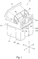
FIG. 1 is a perspective view of a blower according to one embodiment of the present invention from obliquely upward. -
FIG. 2 is a perspective view of the blower from obliquely downward. -
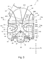
FIG. 3 is a schematic meridional cross-sectional view of the blower, which is a cross-sectional view thereof taken generally along a line III-III depicted inFIG. 5A . -
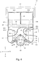
FIG. 4 is a schematic meridional cross-sectional view which is obtained by cutting the blower by a cutting plane orthogonal to a cutting plane ofFIG. 3 , and which is a cross-sectional view thereof taken generally along a line IV-IV depicted inFIG. 5A . -
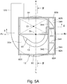
FIG. 5A is a schematic cross-sectional view of the blower taken along a line VA-VA ofFIG. 3 in a state of removing a filter. -
FIG. 5B is a schematic cross-sectional view of the blower taken along a line VB-VB ofFIG. 3 . -
FIG. 6 is a schematic meridional cross-sectional view of a blower according to another embodiment of the present invention. - An embodiment of a blower according to the present invention will be described hereinafter with reference to
FIGS . 1 ,2 ,3 ,4 ,5A , and5B . The blower according to the embodiment is configured as a centrifugal blower used in a two-layer flow type vehicle air conditioner. In each drawing, R signifies a rightward direction of a vehicle, L signifies a leftward direction of the vehicle, Fr signifies a frontward direction of the vehicle, Rr signifies a rearward direction of the vehicle, U signifies an upward direction of the vehicle, and D signifies a downward direction of the vehicle. It should be noted, however, that an installation direction of the centrifugal blower with respect to the vehicle is not limited to an example depicted in the drawings. - As depicted in
FIGS. 3 and4 , acentrifugal blower 1A has animpeller 14. Theimpeller 14 has a plurality ofblades 140 that are disposed in an outer peripheral portion of theimpeller 14 to form a cascade arranged in a peripheral direction. Theimpeller 14 is driven by amotor 16 to rotate about a rotation axis Ax, and blasts out air, which is drawn in a radially inward space of the cascade of theimpeller 14 from axially upward (axially one end side), radially outward. - In the present specification, a direction of the rotation axis Ax of the
motor 16 and theimpeller 14 is referred to as "axial direction" for the sake of convenience. In the following description, the present invention will be described on the premise that the axial direction matches a vertical direction; however, it should be also noted that the air conditioner is often incorporated into a vehicle at an angle formed between the axial direction and the vertical direction. In the present specification, unless specified otherwise, a direction of a radius of a circle described on a plane orthogonal to the rotation axis Ax about an arbitrary point on the rotation axis Ax is referred to as "radial direction" and a circumferential direction of the circle is referred to as "peripheral direction" or "circumferential direction". - The
impeller 14 includes a cone section (inner deflection member) 15 integral molded with theimpeller 14. Thecone section 15 is a body of revolution in a geometrical sense. Arotary shaft 160 of themotor 16 is coupled to theimpeller 14 in a central portion of thecone section 15. - The
impeller 14 is accommodated within ascroll housing 12. Thescroll housing 12 has aninlet port 13 opening axially upward and a delivery port 120 (refer toFIGS. 5A and5B ). As depicted inFIGS. 4 ,5A , and5B , in a case of viewing thescroll housing 12 from the axis direction, thedelivery port 120 extends generally in a tangential direction of an outer peripheral surface of thescroll housing 12. Thedelivery port 120 is invisible inFIG. 3 . - The
scroll housing 12 has apartition wall 18 that extends radially inward from an outer peripheral wall of thescroll housing 12. Thispartition wall 18 axially (vertically) splits a region between an inner peripheral surface of thescroll housing 12 and an outer peripheral surface of theimpeller 14 in an internal space of thescroll housing 12, thereby forming a lowerfirst airflow passage 19 and an uppersecond airflow passage 20 extending along the outer peripheral wall of thescroll housing 12 in the peripheral direction. - As well known in the art, a heat exchange section (section that performs air conditioning by cooling and/or heating by a heat exchanger, an electric heater, or the like), which is not depicted, and an air distribution section (section that regulates blast and distribution of the conditioned air from a plurality of diffusers into a cabin) which have a configuration adapted to a two-layer flow type are provided downstream of the centrifugal blower. A combination of the centrifugal blower, the heat exchange section, and the air distribution section configures the vehicle air conditioner. While the heat exchange section and the air distribution section are integrated to configure a heat exchange/air distribution unit in many cases, the heat exchange section and the air distribution section may be configured as separate units. The air flowing from the lower
first airflow passage 19 within thescroll housing 12 passes through a lower airflow path (not depicted) formed in the heat exchange section, while the air flowing from the uppersecond airflow passage 20 passes through an upper airflow path (not depicted) in the heat exchange section. - A lower portion of a
separation tube 50 is inserted into thescroll housing 12 via theinlet port 13. As depicted inFIGS. 3 and4 , an upper end portion of theseparation tube 50 is located outside of the scroll housing 12 (axially upward of the inlet port 13), and a lower end portion of the separation tube is located in a radially inward space of the cascade of theimpeller 14. - As clear from
FIGS. 5A and5B , a shape (shape viewed from axially upward) of aninflow opening 51 on an upper end of theseparation tube 50 is generally rectangular. A central portion (that is, portion located within the inlet port 13) of theseparation tube 50 has a circular (or generally circular) cross-section. Therefore, a region, which is outside of theseparation tube 50, of theinlet port 13 has a generally annular shape. - A cross-sectional shape of the
separation tube 50 smoothly shifts from a rectangular shape to a circular shape from the upper end portion to the central portion. A position of a cross-sectional center of theseparation tube 50 smoothly shifts from a cross-sectional center Ct of the upper end portion to a cross-sectional center Cc of the lower end portion. The lower end portion of theseparation tube 50 has a flared shape having a diameter enlarged toward the lower end. Anoutflow opening 52 on the lower end of theseparation tube 50 has a circular shape. - It is impossible or quite difficult, even if possible, to integrally mold the
separation tube 50 having the shapes depicted in the drawings by a resin injection molding technique. It is, therefore, preferable to manufacture theseparation tube 50 by coupling two or more pieces formed separately by injection molding by a technique such as bonding, fitting, or screwing. At least part of theseparation tube 50 may be integrally molded with either at least part of thescroll housing 12 or at least part of anair intake housing 30, to be described later. - The
separation tube 50 splits a flow of the air drawn in by suction into thescroll housing 12, into a first airflow that passes through the inner side of theseparation tube 50 and that flows into a lower half portion (first axial portion) 141 of the cascade of theimpeller 14 and a second airflow that passes through the outer side of theseparation tube 50 and that flows into an upper half portion (second axial portion) 142 of the cascade of theimpeller 14. The first airflow flowing out generally axially from theoutflow opening 52 on the lower end of theseparation tube 50 is turned to a radially outward flow by thecone section 15 and flows into the lower half portion (first axial portion) 141 of the cascade of theimpeller 14. The second air flow passing through a portion, which is on the outer side of theseparation tube 50, of theinlet port 13 of thescroll housing 12 is turned to a radially outward flow by the flared lower end portion of theseparation tube 50 and flows into the upper half portion (second axial portion) 142 of the cascade of theimpeller 14. - To improve separation of the first airflow from the second airflow, the
blades 140 of theimpeller 14 are bound by a separation band 143 extending in the circumferential direction to divide thelower half portion 141 from theupper half portion 142 of the blades. - The
air intake housing 30 is coupled to an upper side of thescroll housing 12. Thescroll housing 12 and theair intake housing 30 may be integrally molded or may be coupled together by the technique such as screwing, bonding, or fitting after separately producing thescroll housing 12 and theair intake housing 30. Thescroll housing 12 and theair intake housing 30 form part of an air conditioner casing. - The
air intake housing 30 has anoutside air intake 31 opening generally forward and aninside air intake 32 opening generally rearward. Theinside air intake 32 may be open generally leftward and rightward. Theoutside air intake 31 is coupled to an outlet of an outside air introduction path (not depicted) provided in the vehicle or in the vicinity of the outlet. The outside air (air taken in from outside of the vehicle) can be introduced into theair intake housing 30 via theoutside air intake 31. Theinside air intake 32 is open into the cabin of the vehicle and can introduce the inside air (cabin air) into theair intake housing 30. - A
left switching door 40A and aright switching door 40B are provided side by side in a transverse direction in theair intake housing 30. - The
left switching door 40A can be swung by an actuator, which is not depicted, between a first position at which theleft switching door 40A opens a left half portion of theoutside air intake 31 and closes a left half portion (meaning both a left half of an opening facing rearward and an opening facing leftward of theinside air intake 32, the same applies hereinafter) of theinside air intake 32, and a second position at which theleft switching door 40A closes the left half portion of theoutside air intake 31 and opens the left half portion of theinside air intake 32, about a swing axis extending in the transverse direction. - The
right switching door 40B can be swung by an actuator, which is not depicted, between a first position at which theright switching door 40B opens a right half portion of theoutside air intake 31 and closes a right half portion (meaning both a right half of an opening facing rearward and an opening facing rightward of theinside air intake 32, the same applies hereinafter) of theinside air intake 32, and a second position at which theright switching door 40B closes the right half portion of theoutside air intake 31 and opens the right half portion of theinside air intake 32, about a swing axis collinear with the swing axis of theleft switching door 40A. - The
left switching door 40A and theright switching door 40B are each of a type called rotary door, and have a columnar shape having a fan-shaped bottom surface as a whole. Each of the switching doors (40A and 40B) has a peripheral surface having a circular arc cross-section about the swing axis and fan-shaped side surfaces connected to left and right sides of this peripheral surface. The peripheral surface blocks the outside air intake 31 (inside air intake 32), thereby closing the outside air intake 31 (inside air intake 32). - The
right switching door 40B is located immediately on theinflow opening 51 on the upper end of theseparation tube 50. Theleft switching door 40A is located immediately on a region that adjoins theinflow opening 51 leftward and that is a generally rectangular region in a view from upward within theair intake housing 30. - When the air conditioner is operated in a two-layer flow mode, the
left switching door 40A is located at the first position and theright switching door 40B is located at the second position. At this time, inside air AR (refer toFIG. 3 ) introduced into theair intake housing 30 from the right half portion of theinside air intake 32 flows into theseparation tube 50 from theinflow opening 51, while outside air AE (refer toFIG. 3 ) introduced into theair intake housing 30 from the left half portion of theoutside air intake 31 flows through the outer side of theseparation tube 50. - As depicted in
FIG. 4 , aseparation wall 33 is provided between theleft switching door 40A and theright switching door 40B. Theseparation wall 33 substantially prevents mixture of the outside air introduced from theoutside air intake 31 and the inside air introduced from theinside air intake 32 within theair intake housing 30 when the air conditioner is operated in the two-layer flow mode. - When the air conditioner is operated in an outside air mode, both the
left switching door 40A and theright switching door 40B are located at the first positions. At this time, only the outside air flows into theair intake housing 30. The outside air introduced into theair intake housing 30 from the right half portion of theoutside air intake 31 flows into theseparation tube 50 from theinflow opening 51, while the outside air introduced into theair intake housing 30 from the left half portion of theoutside air intake 31 flows through the outer side of theseparation tube 50. - When the air conditioner is operated in an inside air mode, both the
left switching door 40A and theright switching door 40B are located at the second positions. At this time, only the inside air flows into theair intake housing 30. The inside air introduced into theair intake housing 30 from the right half portion of theinside air intake 32 flows into theseparation tube 50 from theinflow opening 51, while the inside air introduced into theair intake housing 30 from the left half portion of theinside air intake 32 flows through the outer side of theseparation tube 50. - A
filter 35 that removes contaminants such as dust and particles contained in the air and an unusual odor is provided between a region where theoutside air intake 31 and theinside air intake 32 are provided and theinflow opening 51 on the upper end of theseparation tube 50 within theair intake housing 30. Thefilter 35 is inserted into afilter support section 36 that is provided within theair intake housing 30 and that is formed from a slot or a rail, and is held at a position adjacent to theinflow opening 51 of theseparation tube 50. - Auxiliary
inside air inlets air intake housing 30 slightly downward of theinside air intake 32 and upward of thefilter 35. - The blower has an auxiliary inside
air passage 80 that introduces the inside air AR (refer toFIG. 3 ) introduced into theair intake housing 30 via the auxiliary insideair inlets impeller 14 and farther from theinlet port 13 than thecone section 15 in an internal space of thescroll housing 12. The auxiliary insideair passage 80 is formed, as described in detail below, integrally with thescroll housing 12, or formed separately from thescroll housing 12 and then formed by side covers 81A and 81B and abottom cover 85 attached to thescroll housing 12. - As depicted particularly in
FIGS. 1 and2 , the side covers 81A and 81B extending downward from rear-side two corner portions of theair intake housing 30 that is generally quadrangular in a view from upward are attached to an outer peripheral wall surface of thescroll housing 12. At least part of the side covers 81A and 81B may be integrally molded with thescroll housing 12. While the side covers 81A and 81B, which overlap an outer wall of theair intake housing 30 near the corner portions, are invisible inFIG. 5A , the side covers 81A and 81B are visible inFIG. 5B . Spaces between the side covers 81A and 81B and a side wall of thescroll housing 12 configureupstream passage portions air passage 80. It is to be noted that thefilter 35 is not depicted inFIG. 5A . - An outer wall surface of the
scroll housing 12 has contours generally corresponding to those of part of a planar spiral in a view from directly above. The outer wall surface of theair intake housing 30 has generally rectangular contours in a view from directly above. In a view from directly above, the corner portions of the rectangular contours of theair intake housing 30 protrude from the contours of the planar spiral of thescroll housing 12. The side covers 81A and 81B are provided in the protruding portions. In a view from directly above, the contours of the outer wall surfaces of the side covers 81A and 81B generally match those of the outer wall surface of theair intake housing 30. Since theupstream passage portions air passage 80 are provided using a dead space of the blower as described above, providing theupstream passage portions - As depicted in
FIG. 5A , a plurality ofvertical isolation walls isolated spaces air inlets air intake housing 30 and that have generally rectangular cross-sectional shapes within theair intake housing 30 are provided. Lower ends of thevertical isolation walls filter 35. - Since the
isolated spaces main space 30A in theair intake housing 30 by theisolation walls isolated spaces main space 30A upward of thefilter 35. It is noted that themain space 30A means the internal space of theair intake housing 30 into which the air introduced from theoutside air intake 31 and theinside air intake 32 flows. - Cross-sectional shapes (except for those near upper end portions) of the
upstream passage portions air passage 80 can be understood fromFIG. 5B . Generallyrectangular openings filter 35 are formed on upper ends of theupstream passage portions upstream passage portions air passage 80 change from the shapes depicted inFIG. 5B to rectangular shapes near the upper end portions of theupstream passage portions openings isolated spaces - When passing through the
filter 35, part of the inside air flowing from the auxiliary insideair inlets upstream passage portions air passage 80 possibly flows in a direction of crossing thefilter 35 and possibly flows out into the main space within theair intake housing 30. To prevent or suppress this phenomenon, a partition 350 (refer toFIG. 3 ) extending over a thickness direction of thefilter 35 is preferably provided in thefilter 35. Preferably, contours of a space within thefilter 35 surrounded by thispartition 350 generally match those of theopenings isolated spaces - As depicted in
FIGS. 3 and4 , adownstream passage portion 86 of the auxiliary insideair passage 80 is formed between thebottom cover 85 and a bottom wall of thescroll housing 12. Thebottom cover 85 is also coupled to the side covers 81A and 81B, and the inside air flowing from theupstream passage portions downstream passage portion 86. - As depicted in
FIG. 3 , aperipheral wall 87 that defines a motor storage space for storing themotor 16 is formed in a central portion of thebottom cover 85. Themotor 16 is supported by thescroll housing 12 via abottom cover 60 firmly fixed to the bottom wall of thescroll housing 12. - The
downstream passage portion 86 of the auxiliary insideair passage 80 is an annular space formed around theperipheral wall 87 of thebottom cover 85. A plurality ofopenings 122 are provided in the bottom wall of thescroll housing 12 to be spaced apart in the circumferential direction. The inside air AR (refer toFIG. 3 ) within thedownstream passage portion 86 flows through theopenings 122 into a space downward of thecone section 15 within thescroll housing 12. - An outer peripheral edge of the
cone section 15 is connected to theblades 140 at a position slightly upward of a lower end portion of the firstaxial portion 141 of theblades 140 of theimpeller 14. Therefore, the air (inside air or outside air) passing through theseparation tube 50 passes by an upper region of the firstaxial portion 141 of theblades 141. On the other hand, the inside air introduced from the auxiliary insideair inlets axial portion 141. - When the air conditioner is operated in the two-layer flow mode, the inside air is introduced into the
scroll housing 12 not only through a main route from theinside air intake 32 to an upper portion of the firstaxial portion 141 of theblades 140 by way of theseparation tube 50 but also through a sub route from the auxiliary insideair inlets axial portions 141 of theblades 140 by way of theupstream passage portions downstream passage portion 86 of the auxiliary insideair passage 80 and theopenings 122. In other words, the flow of the inside air introduced into thescroll housing 12 without passing through theinlet port 13 of thescroll housing 12 is present. - Owing to this, it is possible to reduce an inside diameter of the separation tube 50 (inside diameter thereof particularly near the
inlet port 13 of the scroll housing 12) while keeping a total flow rate of the inside air taken in into thescroll housing 12 to a necessary level. If the inside diameter of theseparation tube 50 is reduced, then the airflow resistance of theseparation tube 50 increases and the flow rate of the inside air flowing through theseparation tube 50 is reduced; however, the inside air introduced into thescroll housing 12 through the sub route can compensate for a reduced flow rate. - Reducing the inside diameter of the
separation tube 50 makes it possible to increase an area of the region, on the outer side of theseparation tube 50, of theinlet port 13. It is, therefore, possible to increase a flow rate of the outside air introduced into thescroll housing 12 and eventually increase a maximum blast volume of the blower. - The inside diameter of the
separation tube 50 may be set to the same value as a conventionally designed value without reducing the inside diameter of theseparation tube 50. In this case, it is possible to increase the flow rate of the inside air introduced into thescroll housing 12 by as much as the flow rate of the inside air introduced via the sub route and eventually increase the maximum total blast volume of the blower while keeping the flow rate of the inside air and the flow rate of the outside air introduced into thescroll housing 12 to necessary levels similar to conventionally designed levels. - Furthermore, a cross-sectional area of the
separation tube 50 may be reduced by a value smaller than a cross-sectional area of the sub route. In this case, it is possible to increase both the flow rate of the inside air and the flow rate of the outside air introduced into thescroll housing 12 and eventually increase the maximum total blast volume of the blower. - As described above, by providing the sub route, only the total flow rate of the inside air introduced into the
scroll housing 12 may be increased, only the total flow rate of the outside air introduced into thescroll housing 12 may be increased, or the total flow rate of the inside air and the total flow rate of the outside air introduced into thescroll housing 12 may be increased. - It is noted that not only the air flowing into the
scroll housing 12 through the main route but also the air flowing into thescroll housing 12 through the sub route pass through thefilter 35 in the embodiment. This can enhance cleanliness of the air blasted out from the blower. - As depicted in
FIG. 3 , theblower 1A may be configured such thatvalves 38A and 38B are provided in the auxiliary insideair inlets valves 38A and 38B are opened only in a case in which a difference P1-P2 between a pressure P1 of the outer side of theair intake housing 30 near the auxiliary insideair inlets isolated spaces such valves 38A and 38B. - The
valves 38A and 38B are not necessarily provided. In other words, the auxiliary insideair inlets - While the auxiliary inside
air inlets scroll housing 12 in the embodiment, the present invention is not limited to this example and auxiliary inside air inlets 37C may be provided in the bottom wall of thescroll housing 12 as depicted inFIG. 6 . In this case, a space from the auxiliary inside air inlets 37C to the lower end portions of theblades 140 within thescroll housing 12 is regarded as an auxiliary inside air passage. - Furthermore, at least one switching door that opens and closes the air intake housing and the outside air intake and the inside air intake of the air intake housing is not limited to those depicted in
FIGS. 1 to 5 but may be one depicted inFIG. 6 . - In
FIG. 6 , constituent elements having same or similar functions to those of the constituent elements in the embodiment ofFIGS. 1 to 5B are denoted by the same reference numerals and signs. In an embodiment ofFIG. 6 , a plate-likesingle switching door 40C rotating about a rotation axis opens and closes oneoutside air intake 31 and one insideair intake 32.FIG. 6 depicts a state in which the air conditioner is operated in the two-layer flow mode, and depicts a state in which the outside air AE is introduced from theoutside air intake 31 into theair intake housing 30 and then flows in the outer side of theseparation tube 50 and in which the inside air AR is introduced from theinside air intake 32 into theair intake housing 30 and then flows in the inner side of theseparation tube 50. It is noted that in the outside air mode, the switchingdoor 40C is located at a position rotated generally 40 degrees counterclockwise from a position depicted inFIG. 6 . In the inside air mode, the switchingdoor 40C is located at a position rotated generally 40 degrees clockwise from the position depicted inFIG. 6 . -
- 12:
- scroll housing
- 120:
- delivery port
- 13:
- inlet port
- 14:
- impeller
- 140:
- blade
- 141:
- first axial portion
- 142:
- second axial portion
- 15:
- cone section
- 16:
- motor
- 160:
- rotary shaft
- 18:
- partition wall
- 19:
- first airflow passage
- 20:
- second airflow passage
- 30:
- air intake housing
- 31:
- outside air intake
- 32:
- inside air intake
- 37A, 37B, 37C:
- auxiliary inside air inlet
- 40A, 40B, 40C:
- switching door
- 50:
- separation tube
- 51:
- inflow opening
- 52:
- outflow opening
- 80:
- auxiliary inside air passage
Claims (5)
- A blower used in a vehicle air conditioner, comprising:an impeller (14) including a plurality of blades (140) that form a peripheral cascade and driven to rotate by a rotary shaft (160) of a motor (16), the plurality of blades having a first axial portion (141) adjacent to the motor in an axial direction of the rotary shaft and a second axial portion (142) farther from the motor than the first axial portion;a scroll housing (12) including an internal space that accommodates the impeller (14), an inlet port (13) opening in the axial direction of the rotary shaft, and a delivery port (120) opening in a peripheral direction of the impeller;a partition wall (18) that splits a region between an inner peripheral surface of the scroll housing and an outer peripheral surface of the impeller and an internal space of the delivery port (120) in the internal space of the scroll housing (12) in the axial direction to form a first airflow passage (19) and a second airflow passage (20);an air intake housing (30) having an internal space communicating with the inlet port (13) of the scroll housing (12), at least one outside air intake (31) for taking in outside air into the internal space of the air intake housing and at least one inside air intake (32) for taking in inside air into the internal space of the air intake housing being provided in the air intake housing (30);at least one switching door (40A, 40B, 40C) that opens and closes the outside air intake (31) and the inside air intake (32);a separation tube (50) extending through the inlet port (13) of the scroll housing (12), the separation tube including an inflow opening (51) in the air intake housing (30) for flowing air into the separation tube and an outflow opening (52) inside of the peripheral cascade of the impeller (14) within the scroll housing (12) for flowing out the air from within the separation tube, and the separation tube (50) being configured such that the air introduced into the scroll housing (12) via the outflow opening (52) of the separation tube is guided to the first airflow passage (19) of the scroll housing (12) via the first axial portion (141) of the blades of the impeller (14), and that the air introduced into the scroll housing (12) through an outer side of the separation tube (50) and an inner side of the inlet port (13) is guided to the second airflow passage (20) via the second axial portion (142) of the blades of the impeller (14); anda cone section (15) that is provided in the impeller (14) and that turns the air flowing from the outflow opening (52) of the separation tube (50) to an inner side of the peripheral cascade of the impeller (14) toward the first axial portion (141) of the blades of the impeller (14),the blower characterized by further comprising:at least one auxiliary inside air inlet (37A, 37B, 37C) provided in at least one of the scroll housing (12) and the air intake housing (30); andan auxiliary inside air passage (80) introducing the inside air introduced from the auxiliary inside air inlet (37A, 37B, 37C) to a region within the scroll housing (12) farther from the inlet port (13) than the cone section (15) on the inner side of the peripheral cascade of the impeller (14).
- The blower according to claim 1, wherein
the air intake housing (30) includes a filter support section (36) that supports a filter (35), the auxiliary inside air inlet (37A, 37B) is provided at a position at which the auxiliary inside air inlet (37A, 37B) can introduce the inside air into a space upstream of the filter supported by the filter support section within the air intake housing (30), and the inside air introduced from the auxiliary inside air inlet (37A, 37B) passes through the filter (35) and flows into the auxiliary inside air passage (80). - The blower according to claim 2, wherein
in a view from a direction of a rotation axis (Ax) of the impeller, a portion of the scroll housing (12) except for the delivery port (120) is generally spiral, the air intake housing (30) is generally quadrangular, three corner portions of the air intake housing (30) project outside of the scroll housing (12), and the auxiliary inside air passage (80) extends along an outer surface of the scroll housing (12) from at least one of the three corner portions of the air intake housing (30) projecting outside of the scroll housing (12). - The blower according to claim 3, wherein
the auxiliary inside air passage (80) includes two or three passage portions (82A, 82B), and the passage portions (82A, 82B) extend along the outer surface of the scroll housing (12) from two or three corner portions out of the three corner portions of the air intake housing (30) projecting outside of the scroll housing (12). - The blower according to claim 3, further comprising
the generally quadrangular filter (35) supported by the filter support section, wherein an opening (83A, 83B) is provided in an upstream end of the auxiliary inside air passage (80), and a partition member (350), which divides a corner region of the filter overlapping the opening (83A, 83B) from a center-side region present closer to a center side of the filter than the corner region in the view from the direction of the rotation axis (Ax) of the impeller, is provided in the filter (35).
Applications Claiming Priority (1)
| Application Number | Priority Date | Filing Date | Title |
|---|---|---|---|
| JP2018107990A JP2019209856A (en) | 2018-06-05 | 2018-06-05 | Fan |
Publications (2)
| Publication Number | Publication Date |
|---|---|
| EP3578826A1 true EP3578826A1 (en) | 2019-12-11 |
| EP3578826B1 EP3578826B1 (en) | 2022-01-26 |
Family
ID=66589459
Family Applications (1)
| Application Number | Title | Priority Date | Filing Date |
|---|---|---|---|
| EP19175162.7A Not-in-force EP3578826B1 (en) | 2018-06-05 | 2019-05-17 | Blower |
Country Status (2)
| Country | Link |
|---|---|
| EP (1) | EP3578826B1 (en) |
| JP (1) | JP2019209856A (en) |
Cited By (1)
| Publication number | Priority date | Publication date | Assignee | Title |
|---|---|---|---|---|
| CN119042147A (en) * | 2024-10-28 | 2024-11-29 | 中能(辽宁)风电技术有限公司 | Self-filtering low-noise centrifugal fan |
Families Citing this family (3)
| Publication number | Priority date | Publication date | Assignee | Title |
|---|---|---|---|---|
| CN116133880A (en) * | 2020-11-02 | 2023-05-16 | 法雷奥日本株式会社 | Filters and Centrifugal Fans |
| JP7527253B2 (en) * | 2021-07-30 | 2024-08-02 | 株式会社ヴァレオジャパン | Filters and centrifugal blowers for vehicle air conditioning |
| JP2023141886A (en) * | 2022-03-24 | 2023-10-05 | 株式会社ヴァレオジャパン | Air conditioner for vehicle |
Citations (4)
| Publication number | Priority date | Publication date | Assignee | Title |
|---|---|---|---|---|
| JP2000203235A (en) | 1998-12-30 | 2000-07-25 | Valeo Climatisation | Heating, ventilating and/or air conditioning device |
| WO2017163631A1 (en) * | 2016-03-22 | 2017-09-28 | 株式会社日本クライメイトシステムズ | Blower device for air-conditioning of vehicle |
| WO2018074339A1 (en) * | 2016-10-18 | 2018-04-26 | 株式会社ヴァレオジャパン | Centrifugal blower |
| EP3447300A1 (en) * | 2017-08-25 | 2019-02-27 | Valeo Japan Co., Ltd. | Centrifugal blower unit for in-vehicle air conditioner |
Family Cites Families (7)
| Publication number | Priority date | Publication date | Assignee | Title |
|---|---|---|---|---|
| JPS5724566Y2 (en) * | 1978-06-05 | 1982-05-28 | ||
| JP3293537B2 (en) * | 1997-08-11 | 2002-06-17 | 株式会社デンソー | Vehicle air conditioner |
| JP2003165322A (en) * | 2001-11-28 | 2003-06-10 | Denso Corp | Vehicle air conditioner |
| JP2007118630A (en) * | 2005-10-25 | 2007-05-17 | Valeo Thermal Systems Japan Corp | Method and device for controlling inside and outside air switching device of air-conditioner for automobile |
| JP2015067260A (en) * | 2013-10-01 | 2015-04-13 | 株式会社デンソー | Air conditioner for vehicles |
| FR3014173B1 (en) * | 2013-12-04 | 2019-05-17 | Valeo Systemes Thermiques | AIR INLET HOUSING FOR A HEATING, VENTILATION AND / OR AIR CONDITIONING SYSTEM NOW A RECYCLED FLOW OF AIR WITH FRESH AIR INPUT |
| FR3014174B1 (en) * | 2013-12-04 | 2019-05-17 | Valeo Systemes Thermiques | AIR INLET HOUSING FOR LOW PRESSURE HEATING, VENTILATION AND / OR AIR CONDITIONING SYSTEM |
-
2018
- 2018-06-05 JP JP2018107990A patent/JP2019209856A/en active Pending
-
2019
- 2019-05-17 EP EP19175162.7A patent/EP3578826B1/en not_active Not-in-force
Patent Citations (4)
| Publication number | Priority date | Publication date | Assignee | Title |
|---|---|---|---|---|
| JP2000203235A (en) | 1998-12-30 | 2000-07-25 | Valeo Climatisation | Heating, ventilating and/or air conditioning device |
| WO2017163631A1 (en) * | 2016-03-22 | 2017-09-28 | 株式会社日本クライメイトシステムズ | Blower device for air-conditioning of vehicle |
| WO2018074339A1 (en) * | 2016-10-18 | 2018-04-26 | 株式会社ヴァレオジャパン | Centrifugal blower |
| EP3447300A1 (en) * | 2017-08-25 | 2019-02-27 | Valeo Japan Co., Ltd. | Centrifugal blower unit for in-vehicle air conditioner |
Cited By (1)
| Publication number | Priority date | Publication date | Assignee | Title |
|---|---|---|---|---|
| CN119042147A (en) * | 2024-10-28 | 2024-11-29 | 中能(辽宁)风电技术有限公司 | Self-filtering low-noise centrifugal fan |
Also Published As
| Publication number | Publication date |
|---|---|
| EP3578826B1 (en) | 2022-01-26 |
| JP2019209856A (en) | 2019-12-12 |
Similar Documents
| Publication | Publication Date | Title |
|---|---|---|
| EP3578826B1 (en) | Blower | |
| JP7097230B2 (en) | Centrifugal blower | |
| CN110168231B (en) | Centrifugal blower | |
| JPWO2018074339A1 (en) | Centrifugal blower | |
| JP2019044739A (en) | Centrifugal blower for air conditioner for vehicle | |
| JP6862290B2 (en) | Centrifugal blower for vehicle air conditioners | |
| WO2018043640A1 (en) | Centrifugal blower for vehicle air conditioner | |
| JP7200824B2 (en) | centrifugal blower | |
| JP2018091274A (en) | Centrifugal blower | |
| US11499568B2 (en) | Centrifugal fan and centrifugal blower | |
| US11988226B2 (en) | Centrifugal blower | |
| US11852163B2 (en) | Single suction centrifugal blower | |
| JP2018155151A (en) | Centrifugal blower for vehicular air conditioner | |
| WO2019022115A1 (en) | CENTRIFUGAL FAN | |
| JP6685249B2 (en) | Centrifugal blower | |
| US20220282735A1 (en) | Blower | |
| CN113286715B (en) | Centrifugal blower | |
| JP2021071097A (en) | Blower | |
| CN113580878A (en) | Heating, ventilation and air conditioning module and vehicle | |
| WO2021187175A1 (en) | Centrifugal blower | |
| JP7255448B2 (en) | Blower | |
| JP2018193903A (en) | Centrifugal blower |
Legal Events
| Date | Code | Title | Description |
|---|---|---|---|
| PUAI | Public reference made under article 153(3) epc to a published international application that has entered the european phase |
Free format text: ORIGINAL CODE: 0009012 |
|
| STAA | Information on the status of an ep patent application or granted ep patent |
Free format text: STATUS: THE APPLICATION HAS BEEN PUBLISHED |
|
| AK | Designated contracting states |
Kind code of ref document: A1 Designated state(s): AL AT BE BG CH CY CZ DE DK EE ES FI FR GB GR HR HU IE IS IT LI LT LU LV MC MK MT NL NO PL PT RO RS SE SI SK SM TR |
|
| AX | Request for extension of the european patent |
Extension state: BA ME |
|
| STAA | Information on the status of an ep patent application or granted ep patent |
Free format text: STATUS: REQUEST FOR EXAMINATION WAS MADE |
|
| 17P | Request for examination filed |
Effective date: 20200608 |
|
| RBV | Designated contracting states (corrected) |
Designated state(s): AL AT BE BG CH CY CZ DE DK EE ES FI FR GB GR HR HU IE IS IT LI LT LU LV MC MK MT NL NO PL PT RO RS SE SI SK SM TR |
|
| GRAP | Despatch of communication of intention to grant a patent |
Free format text: ORIGINAL CODE: EPIDOSNIGR1 |
|
| STAA | Information on the status of an ep patent application or granted ep patent |
Free format text: STATUS: GRANT OF PATENT IS INTENDED |
|
| INTG | Intention to grant announced |
Effective date: 20210813 |
|
| GRAS | Grant fee paid |
Free format text: ORIGINAL CODE: EPIDOSNIGR3 |
|
| GRAA | (expected) grant |
Free format text: ORIGINAL CODE: 0009210 |
|
| STAA | Information on the status of an ep patent application or granted ep patent |
Free format text: STATUS: THE PATENT HAS BEEN GRANTED |
|
| AK | Designated contracting states |
Kind code of ref document: B1 Designated state(s): AL AT BE BG CH CY CZ DE DK EE ES FI FR GB GR HR HU IE IS IT LI LT LU LV MC MK MT NL NO PL PT RO RS SE SI SK SM TR |
|
| REG | Reference to a national code |
Ref country code: GB Ref legal event code: FG4D |
|
| REG | Reference to a national code |
Ref country code: CH Ref legal event code: EP |
|
| REG | Reference to a national code |
Ref country code: AT Ref legal event code: REF Ref document number: 1465489 Country of ref document: AT Kind code of ref document: T Effective date: 20220215 |
|
| REG | Reference to a national code |
Ref country code: IE Ref legal event code: FG4D |
|
| REG | Reference to a national code |
Ref country code: DE Ref legal event code: R096 Ref document number: 602019011142 Country of ref document: DE |
|
| REG | Reference to a national code |
Ref country code: LT Ref legal event code: MG9D |
|
| REG | Reference to a national code |
Ref country code: NL Ref legal event code: MP Effective date: 20220126 |
|
| REG | Reference to a national code |
Ref country code: AT Ref legal event code: MK05 Ref document number: 1465489 Country of ref document: AT Kind code of ref document: T Effective date: 20220126 |
|
| PG25 | Lapsed in a contracting state [announced via postgrant information from national office to epo] |
Ref country code: NL Free format text: LAPSE BECAUSE OF FAILURE TO SUBMIT A TRANSLATION OF THE DESCRIPTION OR TO PAY THE FEE WITHIN THE PRESCRIBED TIME-LIMIT Effective date: 20220126 |
|
| PG25 | Lapsed in a contracting state [announced via postgrant information from national office to epo] |
Ref country code: SE Free format text: LAPSE BECAUSE OF FAILURE TO SUBMIT A TRANSLATION OF THE DESCRIPTION OR TO PAY THE FEE WITHIN THE PRESCRIBED TIME-LIMIT Effective date: 20220126 Ref country code: RS Free format text: LAPSE BECAUSE OF FAILURE TO SUBMIT A TRANSLATION OF THE DESCRIPTION OR TO PAY THE FEE WITHIN THE PRESCRIBED TIME-LIMIT Effective date: 20220126 Ref country code: PT Free format text: LAPSE BECAUSE OF FAILURE TO SUBMIT A TRANSLATION OF THE DESCRIPTION OR TO PAY THE FEE WITHIN THE PRESCRIBED TIME-LIMIT Effective date: 20220526 Ref country code: NO Free format text: LAPSE BECAUSE OF FAILURE TO SUBMIT A TRANSLATION OF THE DESCRIPTION OR TO PAY THE FEE WITHIN THE PRESCRIBED TIME-LIMIT Effective date: 20220426 Ref country code: LT Free format text: LAPSE BECAUSE OF FAILURE TO SUBMIT A TRANSLATION OF THE DESCRIPTION OR TO PAY THE FEE WITHIN THE PRESCRIBED TIME-LIMIT Effective date: 20220126 Ref country code: HR Free format text: LAPSE BECAUSE OF FAILURE TO SUBMIT A TRANSLATION OF THE DESCRIPTION OR TO PAY THE FEE WITHIN THE PRESCRIBED TIME-LIMIT Effective date: 20220126 Ref country code: ES Free format text: LAPSE BECAUSE OF FAILURE TO SUBMIT A TRANSLATION OF THE DESCRIPTION OR TO PAY THE FEE WITHIN THE PRESCRIBED TIME-LIMIT Effective date: 20220126 Ref country code: BG Free format text: LAPSE BECAUSE OF FAILURE TO SUBMIT A TRANSLATION OF THE DESCRIPTION OR TO PAY THE FEE WITHIN THE PRESCRIBED TIME-LIMIT Effective date: 20220426 |
|
| PG25 | Lapsed in a contracting state [announced via postgrant information from national office to epo] |
Ref country code: PL Free format text: LAPSE BECAUSE OF FAILURE TO SUBMIT A TRANSLATION OF THE DESCRIPTION OR TO PAY THE FEE WITHIN THE PRESCRIBED TIME-LIMIT Effective date: 20220126 Ref country code: LV Free format text: LAPSE BECAUSE OF FAILURE TO SUBMIT A TRANSLATION OF THE DESCRIPTION OR TO PAY THE FEE WITHIN THE PRESCRIBED TIME-LIMIT Effective date: 20220126 Ref country code: GR Free format text: LAPSE BECAUSE OF FAILURE TO SUBMIT A TRANSLATION OF THE DESCRIPTION OR TO PAY THE FEE WITHIN THE PRESCRIBED TIME-LIMIT Effective date: 20220427 Ref country code: FI Free format text: LAPSE BECAUSE OF FAILURE TO SUBMIT A TRANSLATION OF THE DESCRIPTION OR TO PAY THE FEE WITHIN THE PRESCRIBED TIME-LIMIT Effective date: 20220126 Ref country code: AT Free format text: LAPSE BECAUSE OF FAILURE TO SUBMIT A TRANSLATION OF THE DESCRIPTION OR TO PAY THE FEE WITHIN THE PRESCRIBED TIME-LIMIT Effective date: 20220126 |
|
| PG25 | Lapsed in a contracting state [announced via postgrant information from national office to epo] |
Ref country code: IS Free format text: LAPSE BECAUSE OF FAILURE TO SUBMIT A TRANSLATION OF THE DESCRIPTION OR TO PAY THE FEE WITHIN THE PRESCRIBED TIME-LIMIT Effective date: 20220526 |
|
| REG | Reference to a national code |
Ref country code: DE Ref legal event code: R097 Ref document number: 602019011142 Country of ref document: DE |
|
| PG25 | Lapsed in a contracting state [announced via postgrant information from national office to epo] |
Ref country code: SM Free format text: LAPSE BECAUSE OF FAILURE TO SUBMIT A TRANSLATION OF THE DESCRIPTION OR TO PAY THE FEE WITHIN THE PRESCRIBED TIME-LIMIT Effective date: 20220126 Ref country code: SK Free format text: LAPSE BECAUSE OF FAILURE TO SUBMIT A TRANSLATION OF THE DESCRIPTION OR TO PAY THE FEE WITHIN THE PRESCRIBED TIME-LIMIT Effective date: 20220126 Ref country code: RO Free format text: LAPSE BECAUSE OF FAILURE TO SUBMIT A TRANSLATION OF THE DESCRIPTION OR TO PAY THE FEE WITHIN THE PRESCRIBED TIME-LIMIT Effective date: 20220126 Ref country code: EE Free format text: LAPSE BECAUSE OF FAILURE TO SUBMIT A TRANSLATION OF THE DESCRIPTION OR TO PAY THE FEE WITHIN THE PRESCRIBED TIME-LIMIT Effective date: 20220126 Ref country code: DK Free format text: LAPSE BECAUSE OF FAILURE TO SUBMIT A TRANSLATION OF THE DESCRIPTION OR TO PAY THE FEE WITHIN THE PRESCRIBED TIME-LIMIT Effective date: 20220126 Ref country code: CZ Free format text: LAPSE BECAUSE OF FAILURE TO SUBMIT A TRANSLATION OF THE DESCRIPTION OR TO PAY THE FEE WITHIN THE PRESCRIBED TIME-LIMIT Effective date: 20220126 |
|
| PG25 | Lapsed in a contracting state [announced via postgrant information from national office to epo] |
Ref country code: AL Free format text: LAPSE BECAUSE OF FAILURE TO SUBMIT A TRANSLATION OF THE DESCRIPTION OR TO PAY THE FEE WITHIN THE PRESCRIBED TIME-LIMIT Effective date: 20220126 |
|
| PLBE | No opposition filed within time limit |
Free format text: ORIGINAL CODE: 0009261 |
|
| STAA | Information on the status of an ep patent application or granted ep patent |
Free format text: STATUS: NO OPPOSITION FILED WITHIN TIME LIMIT |
|
| REG | Reference to a national code |
Ref country code: CH Ref legal event code: PL |
|
| 26N | No opposition filed |
Effective date: 20221027 |
|
| REG | Reference to a national code |
Ref country code: BE Ref legal event code: MM Effective date: 20220531 |
|
| PG25 | Lapsed in a contracting state [announced via postgrant information from national office to epo] |
Ref country code: MC Free format text: LAPSE BECAUSE OF FAILURE TO SUBMIT A TRANSLATION OF THE DESCRIPTION OR TO PAY THE FEE WITHIN THE PRESCRIBED TIME-LIMIT Effective date: 20220126 Ref country code: LU Free format text: LAPSE BECAUSE OF NON-PAYMENT OF DUE FEES Effective date: 20220517 Ref country code: LI Free format text: LAPSE BECAUSE OF NON-PAYMENT OF DUE FEES Effective date: 20220531 Ref country code: CH Free format text: LAPSE BECAUSE OF NON-PAYMENT OF DUE FEES Effective date: 20220531 |
|
| PG25 | Lapsed in a contracting state [announced via postgrant information from national office to epo] |
Ref country code: SI Free format text: LAPSE BECAUSE OF FAILURE TO SUBMIT A TRANSLATION OF THE DESCRIPTION OR TO PAY THE FEE WITHIN THE PRESCRIBED TIME-LIMIT Effective date: 20220126 |
|
| PG25 | Lapsed in a contracting state [announced via postgrant information from national office to epo] |
Ref country code: IE Free format text: LAPSE BECAUSE OF NON-PAYMENT OF DUE FEES Effective date: 20220517 |
|
| PG25 | Lapsed in a contracting state [announced via postgrant information from national office to epo] |
Ref country code: BE Free format text: LAPSE BECAUSE OF NON-PAYMENT OF DUE FEES Effective date: 20220531 |
|
| PG25 | Lapsed in a contracting state [announced via postgrant information from national office to epo] |
Ref country code: IT Free format text: LAPSE BECAUSE OF FAILURE TO SUBMIT A TRANSLATION OF THE DESCRIPTION OR TO PAY THE FEE WITHIN THE PRESCRIBED TIME-LIMIT Effective date: 20220126 |
|
| PGFP | Annual fee paid to national office [announced via postgrant information from national office to epo] |
Ref country code: FR Payment date: 20230523 Year of fee payment: 5 Ref country code: DE Payment date: 20230510 Year of fee payment: 5 |
|
| P01 | Opt-out of the competence of the unified patent court (upc) registered |
Effective date: 20230629 |
|
| GBPC | Gb: european patent ceased through non-payment of renewal fee |
Effective date: 20230517 |
|
| PG25 | Lapsed in a contracting state [announced via postgrant information from national office to epo] |
Ref country code: MK Free format text: LAPSE BECAUSE OF FAILURE TO SUBMIT A TRANSLATION OF THE DESCRIPTION OR TO PAY THE FEE WITHIN THE PRESCRIBED TIME-LIMIT Effective date: 20220126 Ref country code: CY Free format text: LAPSE BECAUSE OF FAILURE TO SUBMIT A TRANSLATION OF THE DESCRIPTION OR TO PAY THE FEE WITHIN THE PRESCRIBED TIME-LIMIT Effective date: 20220126 Ref country code: GB Free format text: LAPSE BECAUSE OF NON-PAYMENT OF DUE FEES Effective date: 20230517 |
|
| PG25 | Lapsed in a contracting state [announced via postgrant information from national office to epo] |
Ref country code: HU Free format text: LAPSE BECAUSE OF FAILURE TO SUBMIT A TRANSLATION OF THE DESCRIPTION OR TO PAY THE FEE WITHIN THE PRESCRIBED TIME-LIMIT; INVALID AB INITIO Effective date: 20190517 |
|
| PG25 | Lapsed in a contracting state [announced via postgrant information from national office to epo] |
Ref country code: MT Free format text: LAPSE BECAUSE OF FAILURE TO SUBMIT A TRANSLATION OF THE DESCRIPTION OR TO PAY THE FEE WITHIN THE PRESCRIBED TIME-LIMIT Effective date: 20220126 |
|
| REG | Reference to a national code |
Ref country code: DE Ref legal event code: R119 Ref document number: 602019011142 Country of ref document: DE |
|
| PG25 | Lapsed in a contracting state [announced via postgrant information from national office to epo] |
Ref country code: DE Free format text: LAPSE BECAUSE OF NON-PAYMENT OF DUE FEES Effective date: 20241203 |
|
| PG25 | Lapsed in a contracting state [announced via postgrant information from national office to epo] |
Ref country code: FR Free format text: LAPSE BECAUSE OF NON-PAYMENT OF DUE FEES Effective date: 20240531 |
|
| PG25 | Lapsed in a contracting state [announced via postgrant information from national office to epo] |
Ref country code: TR Free format text: LAPSE BECAUSE OF FAILURE TO SUBMIT A TRANSLATION OF THE DESCRIPTION OR TO PAY THE FEE WITHIN THE PRESCRIBED TIME-LIMIT Effective date: 20220126 |