EP3578801A1 - Fuel pump assembly - Google Patents
Fuel pump assembly Download PDFInfo
- Publication number
- EP3578801A1 EP3578801A1 EP18176369.9A EP18176369A EP3578801A1 EP 3578801 A1 EP3578801 A1 EP 3578801A1 EP 18176369 A EP18176369 A EP 18176369A EP 3578801 A1 EP3578801 A1 EP 3578801A1
- Authority
- EP
- European Patent Office
- Prior art keywords
- pump head
- clamping
- clamping plate
- inlet valve
- attachment
- Prior art date
- Legal status (The legal status is an assumption and is not a legal conclusion. Google has not performed a legal analysis and makes no representation as to the accuracy of the status listed.)
- Granted
Links
Images


Classifications
-
- F—MECHANICAL ENGINEERING; LIGHTING; HEATING; WEAPONS; BLASTING
- F02—COMBUSTION ENGINES; HOT-GAS OR COMBUSTION-PRODUCT ENGINE PLANTS
- F02M—SUPPLYING COMBUSTION ENGINES IN GENERAL WITH COMBUSTIBLE MIXTURES OR CONSTITUENTS THEREOF
- F02M59/00—Pumps specially adapted for fuel-injection and not provided for in groups F02M39/00 -F02M57/00, e.g. rotary cylinder-block type of pumps
- F02M59/44—Details, components parts, or accessories not provided for in, or of interest apart from, the apparatus of groups F02M59/02 - F02M59/42; Pumps having transducers, e.g. to measure displacement of pump rack or piston
- F02M59/46—Valves
- F02M59/464—Inlet valves of the check valve type
-
- F—MECHANICAL ENGINEERING; LIGHTING; HEATING; WEAPONS; BLASTING
- F02—COMBUSTION ENGINES; HOT-GAS OR COMBUSTION-PRODUCT ENGINE PLANTS
- F02M—SUPPLYING COMBUSTION ENGINES IN GENERAL WITH COMBUSTIBLE MIXTURES OR CONSTITUENTS THEREOF
- F02M59/00—Pumps specially adapted for fuel-injection and not provided for in groups F02M39/00 -F02M57/00, e.g. rotary cylinder-block type of pumps
- F02M59/44—Details, components parts, or accessories not provided for in, or of interest apart from, the apparatus of groups F02M59/02 - F02M59/42; Pumps having transducers, e.g. to measure displacement of pump rack or piston
- F02M59/48—Assembling; Disassembling; Replacing
- F02M59/485—Means for fixing delivery valve casing and barrel to each other or to pump casing
Definitions
- the present disclosure relates to a fuel pump assembly and particularly, but not exclusively, to a high-pressure fuel pump assembly comprising a clamping plate for attaching an inlet valve to a fuel pump. Aspects of the invention relate to a fuel pump assembly.
- High-pressure fuel pumps for common rail fuel injection systems of compression-ignition internal combustion engines typically comprise one or more hydraulic pump heads where fuel is pressurised in a pumping chamber of the pump head by the reciprocating movement of a plunger.
- low-pressure fuel is fed to the pump heads by a low-pressure lift pump in the fuel tank, or alternatively by a transfer pump built into the high-pressure fuel pump.
- the high-pressure fuel is fed from the pumping chamber to a common rail fuel volume.
- An inlet metering valve is used to regulate the flow of fuel to the high-pressure pump.
- a conventional inlet valve assembly typically comprises a main body with an integrated flange.
- the integrated flange comprises a plurality of apertures configured to receive a fixing means to secure the main body to the pump head.
- Manufacturing the main body of conventional inlet valves is achieved through a complex turning process. This process not only wastes material due to the turning and milling of a large bar of material to manufacture the main housing, but the process also results in an excessive machining cycle time.
- a high-pressure fuel pump assembly comprising a pump head, an inlet valve and a clamping plate attaching the inlet valve to the pump head, wherein the clamping plate comprises: a clamping surface engaged with the inlet valve; an attachment region secured to the pump head, the attachment region comprising an attachment surface engaged with the pump head; and, a deformable connection portion connecting the clamping surface and the attachment region, wherein the connection portion is configured to deform to maintain a flush engagement between the attachment surface and the pump head as the attachment region is secured to the pump head.
- the clamping plate provides the advantage that the fixing means, typically a plurality of screws are subject to minimal non-axial loading the clamping plate is secured to the pump head.
- the connection portion deforms to maintain flush engagement between the attachment surface and the pump head when the clamping plate is secured to the pump head. Furthermore, the deformable connection portions may deform to allow for tolerances in the geometry of the fuel pump assembly resulting from manufacture.
- the clamping plate may comprise three attachment regions and three clamping surfaces alternatively arranged in a substantially circumferential arrangement and wherein the attachment regions and clamping surfaces are connected via six connection portions.
- connection portion may be configured to deform when the clamping plate is secured to the pump head thereby causing a distance defined between the clamping surface and the attachment surface to increase.
- the distance may increase by between 0.1mm and 0.5mm depending on the tolerancing of the inlet valve assembly. Deforming the connection portion helps to maintain flush engagement of the attachment surface and the pump head when the clamping plate is secured to the pump head by the screws.
- the clamping surface may be convex prior to engaging the inlet valve.
- the clamping surface may be configured to deform upon engagement of the inlet valve and the clamping surface may be substantially planar when engaged with the inlet valve. This is advantageous when the clamping plate is required to have an increased stiffness to deliver an increased clamping force.
- the convex clamping surface engages the fuel pump assembly before deforming when the clamping plate is secured to the fuel pump assembly.
- the clamping plate may comprise a locating feature engaged with a corresponding engagement slot on the pump head. This is advantageous as the locating feature enables an operator to locate the clamping plate on the fuel pump prior to securing the clamping plate in place.
- the locating feature may locate the clamping plate such that the attachment regions are orientated correctly to be secured to the pump head.
- the attachment region comprises an aperture through which a screw is located.
- the screw may engage the pump head and provide a clamping force to secure the clamping plate to the pump head.
- embodiments of the invention provide a clamping plate configured to secure an inlet valve assembly to a hydraulic pump head of a high-pressure fuel pump for use in a compression-ignition internal combustion engine.
- the clamping plate comprises a clamping surface configured to engage the main housing of the inlet valve assembly and an attachment region configured to receive a fixing means to attach the clamping plate to the pump head.
- the attachment region and the clamping surface are connected by a deformable connection portion.
- the connection portion is designed to deform when the clamping plate is secured to the pump head such that the attachment region is maintained in flush engagement with the pump head. This is advantageous as maintaining the attachment region flush on the pump head ensures that the fixing means, typically a bolt or screw, experiences minimal non-axial loading.
- FIG. 1 shows an inlet valve assembly 12 suitable for mounting on a pump head 11 (not shown in Figure 1 ) on a high-pressure fuel pump.
- the inlet valve assembly 12 comprises a main body 16, a protective cap 14 and an electrical connector 18 for receiving a control signal to operate the inlet valve assembly 12..
- the inlet valve assembly 12 meters the flow of fuel into the pump head 11 of the high-pressure fuel pump.
- the pressure of the fuel within the inlet valve assembly 12 can reach pressure spikes in the order of 40 bar and as such the valve assembly 12 must be securely attached to the pump head 11 to prevent any leakage of pressurised fuel.
- the main body 16 of the inlet valve assembly 12 comprises an outwardly protruding flange 15 positioned around its periphery.
- the flange 15 provides a sealing means such that a tight seal may be formed between the pump head 11 and the main body 16 when the inlet valve 12 is mounted to the pump head 11.
- a rubber O-ring or gasket (not shown) is located within a groove on the flange 15 to further improve the quality of the seal between the inlet valve assembly 12 and the pump head 11.
- the inlet valve assembly 12 is secured to the pump head 11 by the clamping plate 10 shown in Figure 2 .
- the clamping plate 10 is configured to engage the flange 15 of the main body 16 and to receive fixing means 50a, 50b, such as screws or bolts, to secure the clamping plate 10 to the pump head 11 thereby providing a clamping force to press the main body 16 toward the pump head 11 via the flange 15.
- the clamping plate 10 is a steel ring comprising a central aperture 27.
- the clamping plate 10 is configured to be positioned over the main body 16 of the inlet valve assembly 12 as shown in Figure 2 such that the main body 16 is at least partially received in the central aperture 27.
- the fixing means 50a, 50b (not shown in Figure 2 ) engage the pump head 11 the clamping surfaces 20a, 20b, 20c are pressed toward and engage the flange 15. Pressing the flange 15 toward the pump head 11 in this manner secures the inlet valve assembly 12 to the pump head 11 and achieves a seal between the pump head 11 and the valve assembly 12.
- the clamping plate 10 further comprises a plurality of attachment regions 22a, 22b, 22c configured to receive the fixing means 50a, 50b such that the clamping plate 10 may be secured to the pump head 11.
- the clamping plate 10 comprises three attachment regions 22a, 22b, 22c, however, the skilled person would appreciate that the invention may implemented with as few as a single attachment region or may be worked with more than three attachment regions.
- each attachment region would receive a complementary fixing means.
- the attachment regions 22a, 22b, 22c each comprise an aperture 26a, 26b, 26c for receiving the fixing means 50a, 50b, and an attachment surface 46a, 46b, 46c defined by the bottom surfaces of the attachment regions 22a, 22b, 22c.
- the fixing means 50a, 50b is typically in the form of a bolt or screw. As the fixing means 50a, 50b is tightened the head of the fixing means 50a, 50b engages the top surface of the attachment regions 22a, 22b, 22c thereby pressing the clamping plate 10 towards the pump head 11. This causes the attachment surfaces 46a, 46b, 46c to engage the pump head 11.
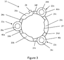
- the clamping plate 10 is shown in further detail in Figure 3 .
- the clamping plate 10 comprises three clamping surfaces 20a, 20b, 20c configured to engage the top surface 17 of the flange 15.
- the clamping surfaces 20a, 20b, 20c of the clamping plate 10 are connected to attachment regions 22a, 22b, 22c by way of connecting portions 24a, 24b, 24c, 24d, 24e, 24f herein referred to "connecting arms".
- the attachment regions 22a, 22b, 22c comprise apertures 26a, 26b, 26c configured to receive the fixing means 50a, 50b to secure the clamping plate 10 to the pump head 11.
- the clamping surfaces 20a, 20b, 20c define a plane vertically offset from a plane defined by the attachment surfaces 46a, 46b, 46c of the attachment regions 22a, 22b, 22c.
- the attachment surface 46a is disposed by a vertical distance 40 below the clamping surfaces 20a, 20b, 20c.
- the distance 40 substantially equals the thickness of the flange 15 such that when the clamping surfaces 20a, 20b engage the flange 15 the attachment region 22a simultaneously engages the pump head 11.
- due to tolerancing constraints during manufacture of the clamping plate 10 and flange 15 there is variation between the distance 40 and the depth of the flange 15.
- the manufacturing tolerance in the distance 40 is designed to be equal to or less than the depth of the flange 15. This is desirable because if the distance 40 was greater than the depth of the flange 15 the clamping surfaces 20a, 20b would not engage the flange 15 when the clamping plate 10 is secured to the pump head 11.
- the connecting arms 24a, 24b are deformable.
- the fixing means 50a is tightened, thereby pressing down on the attachment region 22a and bringing the clamping surfaces 20a, 20b into engagement with the top surface 17 of the flange 15, the connecting arms 24a, 24b deform.
- Deforming the connecting arms 24a, 24b ensures that the attachment surface 46a maintains flush engagement with the pump head 11. Maintaining flush engagement between the attachment surface 46a and the pump head 11 minimises non-axial loading on the fixing means 50a thus ensuring that the majority of loading is imparted along the longitudinal axis of the fixing means 50a.
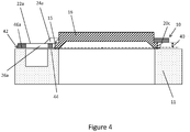
- FIG. 4 shows a cross-sectional schematic view of the clamping plate 10 and the main body 16.
- the clamping plate 10 is shown in a non-deformed position, prior to the clamping plate 10 being secured to the pump head 11 by the fixing means 50a, 50b.
- the gap 42 is typically between 0.2mm and 0.4mm although depending on tolerancing of the clamping plate 10 and flange 15 the gap 42 is typically less than 1mm in length.
- the connecting arms 24a, 24b deform to bring the attachment surface 46 into flush engagement with the engagement surface 44 of the pump head 11. This causes the distance 40 defined between the clamping surface 20a, 20b, 20c and the attachment surface 46a, 46b, 46c to increase by between approximately 0.1mm and 0.5mm.
- the clamping force applied to the clamping plate 10 by the fixing means 50a, 50b is transferred through the connecting arms 24a, 24b and imparted on the flange 15 by the clamping surface 22a, 22b.
- the clamping force imparted on the flange 15 secures the inlet valve assembly 12 to the pump head 11.
- the force imparted on the flange 15 by the clamping surfaces 22a, 22b may be varied by modifying parameters of the connecting arms 24a, 24b.
- the stiffness of the connecting arms 24a, 24b may be controlled by varying, for example, the length, thickness, width and material of the connecting arms 24a, 24b.
- the clamping plate 10 is manufactured from pressed steel, however, the clamping plate may be manufactured from other metals such as aluminium or plastics material.
- the shape of the clamping surfaces 20a, 20b may be convex such that upon engagement between the flange 15 and the clamping surfaces 20a, 20b, the clamping surfaces 20a, 20b deform from their convex shape to a substantially planar surface. Deforming the clamping surfaces 20a, 20b in this manner achieves a larger clamping force to be imparted on the flange 15.
- the connecting arms 24a, 24b may be designed to more easily deform. This is advantageous as in this scenario the tolerances in manufacture of the clamping plate 10 and flange 15 could be larger and taken up by deforming the connecting arms 24a, 24b thus any variations resulting from the larger tolerances can be compensated for.
- the connecting arms 24a, 24b may deform by 1mm or more depending on the application and magnitude of the gap 42. Furthermore, reducing the stiffness of the clamping plate 10 further minimises any non-axial loading imparted on the fixing means 50a, 50b.
- the connecting arms 24a, 24b may be designed to less easily deform. In this situation more of the clamping force exerted by the fixing means 50a, 50b is transferred through the connecting arms 24a, 24b to the flange 15.
- FIG. 5 shows a high-pressure fuel pump assembly 60 comprising the pump head 11, the inlet valve assembly 12 and the clamping plate 10.
- the clamping plate 10 comprises a locating feature 28.
- the locating feature 28 is a tab configured to engage a corresponding engagement slot 52 in the pump head 11.
- the locating feature 28 locates the clamping plate 10 in position relative to the pump head 11 prior to the fitment of the screws 50a, 50b. This is advantageous as it facilitates quick fitment of the screws 50a, 50b to the pump head 11 or electrical component 54 by ensuring the clamping plate 10 is orientated correctly.
Landscapes
- Engineering & Computer Science (AREA)
- Chemical & Material Sciences (AREA)
- Combustion & Propulsion (AREA)
- Mechanical Engineering (AREA)
- General Engineering & Computer Science (AREA)
- Fuel-Injection Apparatus (AREA)
Abstract
Description
- The present disclosure relates to a fuel pump assembly and particularly, but not exclusively, to a high-pressure fuel pump assembly comprising a clamping plate for attaching an inlet valve to a fuel pump. Aspects of the invention relate to a fuel pump assembly.
- High-pressure fuel pumps for common rail fuel injection systems of compression-ignition internal combustion engines typically comprise one or more hydraulic pump heads where fuel is pressurised in a pumping chamber of the pump head by the reciprocating movement of a plunger. Typically, low-pressure fuel is fed to the pump heads by a low-pressure lift pump in the fuel tank, or alternatively by a transfer pump built into the high-pressure fuel pump. Once pressurised, the high-pressure fuel is fed from the pumping chamber to a common rail fuel volume.
- An inlet metering valve is used to regulate the flow of fuel to the high-pressure pump. A conventional inlet valve assembly typically comprises a main body with an integrated flange. The integrated flange comprises a plurality of apertures configured to receive a fixing means to secure the main body to the pump head.
- Manufacturing the main body of conventional inlet valves is achieved through a complex turning process. This process not only wastes material due to the turning and milling of a large bar of material to manufacture the main housing, but the process also results in an excessive machining cycle time.
- It is against this background that the invention has been devised.
- According to an aspect of the present invention there is provided a high-pressure fuel pump assembly comprising a pump head, an inlet valve and a clamping plate attaching the inlet valve to the pump head, wherein the clamping plate comprises: a clamping surface engaged with the inlet valve; an attachment region secured to the pump head, the attachment region comprising an attachment surface engaged with the pump head; and, a deformable connection portion connecting the clamping surface and the attachment region, wherein the connection portion is configured to deform to maintain a flush engagement between the attachment surface and the pump head as the attachment region is secured to the pump head.
- The clamping plate provides the advantage that the fixing means, typically a plurality of screws are subject to minimal non-axial loading the clamping plate is secured to the pump head. The connection portion deforms to maintain flush engagement between the attachment surface and the pump head when the clamping plate is secured to the pump head. Furthermore, the deformable connection portions may deform to allow for tolerances in the geometry of the fuel pump assembly resulting from manufacture.
- In an embodiment the clamping plate may comprise three attachment regions and three clamping surfaces alternatively arranged in a substantially circumferential arrangement and wherein the attachment regions and clamping surfaces are connected via six connection portions.
- In another embodiment the connection portion may be configured to deform when the clamping plate is secured to the pump head thereby causing a distance defined between the clamping surface and the attachment surface to increase.
- The distance may increase by between 0.1mm and 0.5mm depending on the tolerancing of the inlet valve assembly. Deforming the connection portion helps to maintain flush engagement of the attachment surface and the pump head when the clamping plate is secured to the pump head by the screws.
- In an embodiment the clamping surface may be convex prior to engaging the inlet valve. In another embodiment the clamping surface may be configured to deform upon engagement of the inlet valve and the clamping surface may be substantially planar when engaged with the inlet valve. This is advantageous when the clamping plate is required to have an increased stiffness to deliver an increased clamping force. The convex clamping surface engages the fuel pump assembly before deforming when the clamping plate is secured to the fuel pump assembly.
- In one embodiment the clamping plate may comprise a locating feature engaged with a corresponding engagement slot on the pump head. This is advantageous as the locating feature enables an operator to locate the clamping plate on the fuel pump prior to securing the clamping plate in place. The locating feature may locate the clamping plate such that the attachment regions are orientated correctly to be secured to the pump head.
- In another embodiment the attachment region comprises an aperture through which a screw is located. The screw may engage the pump head and provide a clamping force to secure the clamping plate to the pump head.
- In order that the invention may be more readily understood, reference will now be made, by way of example, to the accompanying drawings, in which:
-
Figure 1 is a perspective view of an inlet valve assembly suitable for use with embodiments of the present invention; -
Figure 2 is a perspective view of the inlet valve assembly ofFigure 1 and a clamping plate in accordance with an embodiment of the invention for mounting the inlet valve assembly to a pump head; -
Figure 3 shows a bottom view of the clamping plate ofFigure 2 ;Figure 4 is a cross-sectional view of the inlet valve assembly and clamping plate ofFigure 2 mounted on a pump head; and, -
Figure 5 shows a perspective view of a high-pressure fuel pump assembly suitable for use with embodiments of the present invention. - References in the following description to "top", "bottom" or any other terms having an implied orientation are not intended to be limiting and refer only to the orientation of the parts as shown in the accompanying drawings.
- In general terms, embodiments of the invention provide a clamping plate configured to secure an inlet valve assembly to a hydraulic pump head of a high-pressure fuel pump for use in a compression-ignition internal combustion engine. The clamping plate comprises a clamping surface configured to engage the main housing of the inlet valve assembly and an attachment region configured to receive a fixing means to attach the clamping plate to the pump head. The attachment region and the clamping surface are connected by a deformable connection portion. The connection portion is designed to deform when the clamping plate is secured to the pump head such that the attachment region is maintained in flush engagement with the pump head. This is advantageous as maintaining the attachment region flush on the pump head ensures that the fixing means, typically a bolt or screw, experiences minimal non-axial loading.
- To place embodiments of the invention in a suitable context, reference will firstly be made to
Figure 1 which shows aninlet valve assembly 12 suitable for mounting on a pump head 11 (not shown inFigure 1 ) on a high-pressure fuel pump. Theinlet valve assembly 12 comprises amain body 16, aprotective cap 14 and anelectrical connector 18 for receiving a control signal to operate theinlet valve assembly 12.. - The
inlet valve assembly 12 meters the flow of fuel into thepump head 11 of the high-pressure fuel pump. The pressure of the fuel within theinlet valve assembly 12 can reach pressure spikes in the order of 40 bar and as such thevalve assembly 12 must be securely attached to thepump head 11 to prevent any leakage of pressurised fuel. To overcome this problem themain body 16 of theinlet valve assembly 12 comprises an outwardly protrudingflange 15 positioned around its periphery. Theflange 15 provides a sealing means such that a tight seal may be formed between thepump head 11 and themain body 16 when theinlet valve 12 is mounted to thepump head 11. A rubber O-ring or gasket (not shown) is located within a groove on theflange 15 to further improve the quality of the seal between theinlet valve assembly 12 and thepump head 11. - The
inlet valve assembly 12 is secured to thepump head 11 by theclamping plate 10 shown inFigure 2 . Theclamping plate 10 is configured to engage theflange 15 of themain body 16 and to receivefixing means clamping plate 10 to thepump head 11 thereby providing a clamping force to press themain body 16 toward thepump head 11 via theflange 15. - In the embodiment shown, the
clamping plate 10 is a steel ring comprising acentral aperture 27. Theclamping plate 10 is configured to be positioned over themain body 16 of theinlet valve assembly 12 as shown inFigure 2 such that themain body 16 is at least partially received in thecentral aperture 27. A portion of theclamping plate 10, herein referred to asclamping surfaces flange 15. When the fixing means 50a, 50b (not shown inFigure 2 ) engage thepump head 11 theclamping surfaces flange 15. Pressing theflange 15 toward thepump head 11 in this manner secures theinlet valve assembly 12 to thepump head 11 and achieves a seal between thepump head 11 and thevalve assembly 12. - The
clamping plate 10 further comprises a plurality ofattachment regions fixing means clamping plate 10 may be secured to thepump head 11. In the embodiment shown theclamping plate 10 comprises threeattachment regions - The
attachment regions aperture attachment surface attachment regions attachment regions clamping plate 10 towards thepump head 11. This causes theattachment surfaces pump head 11. It is desirable to maintain a flush engagement between the attachment surfaces 46a, 46b, 46c and thepump head 11 to minimise any non-axial loading on the fixing means 50a, 50b. Thescrews pump housing 54, thus clamping theinlet valve assembly 12 and pumphead 11 down together onto thepump housing 54, as best shown inFigure 5 . - The clamping
plate 10 is shown in further detail inFigure 3 . As previously mentioned the clampingplate 10 comprises three clampingsurfaces top surface 17 of theflange 15. The clamping surfaces 20a, 20b, 20c of the clampingplate 10 are connected toattachment regions portions attachment regions apertures plate 10 to thepump head 11. - For the purposes of clarity, the invention will be described herein with reference to a
single attachment region 22a connected to clampingsurfaces arm - As best shown in
Figure 4 , the clampingsurfaces attachment regions attachment surface 46a is disposed by avertical distance 40 below the clampingsurfaces distance 40 substantially equals the thickness of theflange 15 such that when the clamping surfaces 20a, 20b engage theflange 15 theattachment region 22a simultaneously engages thepump head 11. However, due to tolerancing constraints during manufacture of the clampingplate 10 andflange 15 there is variation between thedistance 40 and the depth of theflange 15. As such, the manufacturing tolerance in thedistance 40 is designed to be equal to or less than the depth of theflange 15. This is desirable because if thedistance 40 was greater than the depth of theflange 15 the clamping surfaces 20a, 20b would not engage theflange 15 when the clampingplate 10 is secured to thepump head 11. - To address variations in the
distance 40 between the clampingsurfaces attachment region 22a, the connectingarms attachment region 22a and bringing the clamping surfaces 20a, 20b into engagement with thetop surface 17 of theflange 15, the connectingarms arms attachment surface 46a maintains flush engagement with thepump head 11. Maintaining flush engagement between theattachment surface 46a and thepump head 11 minimises non-axial loading on the fixing means 50a thus ensuring that the majority of loading is imparted along the longitudinal axis of the fixing means 50a. -
Figure 4 shows a cross-sectional schematic view of the clampingplate 10 and themain body 16. The clampingplate 10 is shown in a non-deformed position, prior to the clampingplate 10 being secured to thepump head 11 by the fixing means 50a, 50b. As a result, there is agap 42 between a top surface orengagement surface 44 of thepump head 11 and a bottom surface or attachment surface 46 of theattachment region 22a. Thegap 42 is typically between 0.2mm and 0.4mm although depending on tolerancing of the clampingplate 10 andflange 15 thegap 42 is typically less than 1mm in length. When the fixing means 50a, 50b is tightened thereby securing the clampingplate 10 to thepump head 11, the connectingarms engagement surface 44 of thepump head 11. This causes thedistance 40 defined between the clampingsurface attachment surface plate 10 by the fixing means 50a, 50b is transferred through the connectingarms flange 15 by the clampingsurface flange 15 secures theinlet valve assembly 12 to thepump head 11. - The force imparted on the
flange 15 by the clampingsurfaces arms arms flange 15. This is advantageous as the connectingarms flange 15 depending on the required clamping force for a particular application of the clamping plate. - The stiffness of the connecting
arms arms plate 10 is manufactured from pressed steel, however, the clamping plate may be manufactured from other metals such as aluminium or plastics material. Furthermore, the shape of the clamping surfaces 20a, 20b may be convex such that upon engagement between theflange 15 and the clamping surfaces 20a, 20b, the clampingsurfaces surfaces flange 15. - For example, if the
inlet valve assembly 12 is subject to a low fluid pressure, the clamping force required to maintain engagement between theinlet valve 12 and thepump head 11 may be relatively low. In this scenario the connectingarms plate 10 andflange 15 could be larger and taken up by deforming the connectingarms arms gap 42. Furthermore, reducing the stiffness of the clampingplate 10 further minimises any non-axial loading imparted on the fixing means 50a, 50b. - Alternatively, in situations where the
inlet valve assembly 12 carries high pressure fluid the clamping force required to maintain engagement between theinlet valve 12 and thepump head 11 is relatively high. In this scenario the connectingarms arms flange 15. -
Figure 5 shows a high-pressurefuel pump assembly 60 comprising thepump head 11, theinlet valve assembly 12 and the clampingplate 10. In the example shown the clampingplate 10 comprises a locatingfeature 28. The locatingfeature 28 is a tab configured to engage acorresponding engagement slot 52 in thepump head 11. The locatingfeature 28 locates the clampingplate 10 in position relative to thepump head 11 prior to the fitment of thescrews screws pump head 11 orelectrical component 54 by ensuring the clampingplate 10 is orientated correctly. - Many modifications may be made to the above examples without departing from the scope of the present invention as defined in the accompanying claims.
-
- 10
- Clamping Plate
- 11
- Pump Head
- 12
- Inlet Valve Assembly
- 14
- Protective Cap
- 15
- Flange
- 16
- Main Body of Inlet Valve Assembly
- 17
- Top Surface of the Flange
- 18
- Electrical Connector
- 20a
- First Clamping Surface
- 20b
- Second Clamping Surface
- 20c
- Third Clamping Surface
- 22a
- First Attachment Region
- 22b
- Second Attachment Region
- 22c
- Third Attachment Region
- 24a
- First Connecting Arm
- 24b
- Second Connecting Arm
- 24c
- Third Connecting Arm
- 24d
- Fourth Connecting Arm
- 24e
- Fifth Connecting Arm
- 24f
- Sixth Connecting Arm
- 26a
- First Aperture
- 26b
- Second Aperture
- 26c
- Third Aperture
- 27
- Central Aperture
- 28
- Locating Feature
- 40
- Distance between Attachment Region and Clamping Surface
- 42
- Gap between Pump Head and Attachment Region
- 44
- Engagement Surface
- 46a
- First Attachment Surface
- 46b
- Second Attachment Surface
- 46c
- Third Attachment Surface
- 50a
- First Screw
- 50b
- Second Screw
- 52
- Engagement Slot
- 54
- Pump Housing
- 60
- High-Pressure Fuel Pump Assembly
Claims (7)
- A high-pressure fuel pump assembly (60) comprising a pump head (11), an inlet valve (12) and a clamping plate (10) attaching the inlet valve (12) to the pump head (11), wherein the clamping plate (10) comprises:a clamping surface (20a, 20b, 20c) engaged with the inlet valve (12);an attachment region (22a, 22b. 22c) secured to the pump head (11), the attachment region (22a, 22b, 22c) comprising an attachment surface (46a, 46b, 46c) engaged with the pump head (11); and,a deformable connection portion (24a, 24b, 24c, 24d, 24e, 24f) connecting the clamping surface (20a, 20b, 20c) and the attachment region (22a, 22b, 22c), wherein the connection portion (24a, 24b, 24c, 24d, 24e, 24f) is configured to deform to maintain a flush engagement between the attachment surface (46a, 46b, 46c) and the pump head (11) as the attachment region (22a, 22b, 22c) is secured to the pump head (11).
- A high-pressure fuel pump assembly (60) as claimed in claim 1, wherein the clamping plate (10) comprises three attachment regions (22a, 22b, 22c) and three clamping surfaces (20a, 20b, 20c) alternatively arranged in a substantially circumferential arrangement and wherein the attachment regions (22a, 22b, 22c) and clamping surfaces (20a, 20b, 20c) are connected via six connection portions (24a, 24b, 24c, 24d, 24e, 24f).
- A high-pressure fuel pump assembly (60) as claimed in claim 1 or claim 2, wherein the connection portion (24a, 24b, 24c, 24d, 24e, 24f) is configured to deform when the clamping plate (10) is secured to the pump head (11) thereby causing a distance (40) defined between the clamping surface (20a, 20b, 20c) and the attachment surface (46a, 46b, 46c) to increase.
- A high-pressure fuel pump assembly (60) as claimed in any preceding claim, wherein the clamping surface (20a, 20b, 20c) is convex prior to engaging the inlet valve (12).
- A high-pressure fuel pump assembly (60) as claimed in claim 4, wherein the clamping surface (20a, 20b, 20c) is configured to deform upon engagement of the inlet valve (12) and wherein the clamping surface (20a, 20b, 20c) is substantially planar when engaged with the inlet valve (12).
- A high-pressure fuel pump assembly (60) as claimed in any preceding claim, wherein the clamping plate (10) comprises a locating feature (28) engaged with a corresponding engagement slot (52) on the pump head (11).
- A high-pressure fuel pump assembly (60) as claimed in any preceding claim, wherein the attachment region (22a, 22b, 22c) comprises an aperture (26a, 26b, 26c) through which a screw (50a, 50b) is located.
Priority Applications (1)
| Application Number | Priority Date | Filing Date | Title |
|---|---|---|---|
| EP18176369.9A EP3578801B1 (en) | 2018-06-06 | 2018-06-06 | Fuel pump assembly |
Applications Claiming Priority (1)
| Application Number | Priority Date | Filing Date | Title |
|---|---|---|---|
| EP18176369.9A EP3578801B1 (en) | 2018-06-06 | 2018-06-06 | Fuel pump assembly |
Publications (2)
| Publication Number | Publication Date |
|---|---|
| EP3578801A1 true EP3578801A1 (en) | 2019-12-11 |
| EP3578801B1 EP3578801B1 (en) | 2021-11-10 |
Family
ID=62563023
Family Applications (1)
| Application Number | Title | Priority Date | Filing Date |
|---|---|---|---|
| EP18176369.9A Active EP3578801B1 (en) | 2018-06-06 | 2018-06-06 | Fuel pump assembly |
Country Status (1)
| Country | Link |
|---|---|
| EP (1) | EP3578801B1 (en) |
Citations (3)
| Publication number | Priority date | Publication date | Assignee | Title |
|---|---|---|---|---|
| US6283772B1 (en) * | 1997-06-07 | 2001-09-04 | Robert Bosch Gmbh | Fastening device for securing a subassembly to a body of a fuel delivery system |
| EP2456981A1 (en) * | 2009-07-20 | 2012-05-30 | Delphi Technologies Holding S.à.r.l. | Pump assembly |
| DE102015218221A1 (en) * | 2015-09-23 | 2017-03-23 | Robert Bosch Gmbh | High-pressure fuel pump, in particular a common rail injection system of an internal combustion engine |
Family Cites Families (1)
| Publication number | Priority date | Publication date | Assignee | Title |
|---|---|---|---|---|
| DE102013202569A1 (en) * | 2013-02-18 | 2014-08-21 | Robert Bosch Gmbh | Assembly comprising pumping element and mounting flange |
-
2018
- 2018-06-06 EP EP18176369.9A patent/EP3578801B1/en active Active
Patent Citations (3)
| Publication number | Priority date | Publication date | Assignee | Title |
|---|---|---|---|---|
| US6283772B1 (en) * | 1997-06-07 | 2001-09-04 | Robert Bosch Gmbh | Fastening device for securing a subassembly to a body of a fuel delivery system |
| EP2456981A1 (en) * | 2009-07-20 | 2012-05-30 | Delphi Technologies Holding S.à.r.l. | Pump assembly |
| DE102015218221A1 (en) * | 2015-09-23 | 2017-03-23 | Robert Bosch Gmbh | High-pressure fuel pump, in particular a common rail injection system of an internal combustion engine |
Also Published As
| Publication number | Publication date |
|---|---|
| EP3578801B1 (en) | 2021-11-10 |
Similar Documents
| Publication | Publication Date | Title |
|---|---|---|
| US7114928B2 (en) | High-pressure fuel pump and assembly structure of high-pressure pump | |
| EP2753820B1 (en) | Fuel injector and fuel injector assembly | |
| EP2208883B1 (en) | Coupling device | |
| EP1653076B1 (en) | Common rail fuel injection apparatus with a flow damper | |
| US10436163B2 (en) | Fuel rail assembly for an internal combustion engine | |
| US6514050B1 (en) | High pressure seal means for a radial piston pump | |
| EP2278163A1 (en) | Pump assembly | |
| CN103562539B (en) | Fuel distributor | |
| EP2375052A1 (en) | Fuel injector assembly | |
| US9803605B2 (en) | Fluid injection assembly | |
| JP2013072430A (en) | Mounting structure of fuel distribution pipe | |
| US10883463B2 (en) | High pressure pump | |
| EP1277950B1 (en) | High-pressure pump | |
| EP3179089B1 (en) | End-sealing structure for fuel rail for gasoline direct injection engine | |
| EP3578801B1 (en) | Fuel pump assembly | |
| US10641222B2 (en) | Fuel injector assembly | |
| US9309820B2 (en) | Device for metering fuel | |
| JP2013238226A (en) | Injector for fuel supply equipment of combustion engine, and the fuel supply equipment | |
| KR101960201B1 (en) | Terminal sealing structure for fuel rail for gasoline direct-injection engine | |
| CN110959069B (en) | fuel injection valve | |
| JP5190340B2 (en) | Common rail | |
| US6685111B2 (en) | Fuel injector and relative production method | |
| US9835151B2 (en) | Hydraulic device, in particular low-pressure accumulator with a closure element | |
| EP3283753B1 (en) | Sealing system of a head of an internal combustion engine with common rail external to the head | |
| US11143154B2 (en) | Fuel system having a connection between a fuel injector and a fuel distribution conduit |
Legal Events
| Date | Code | Title | Description |
|---|---|---|---|
| STAA | Information on the status of an ep patent application or granted ep patent |
Free format text: STATUS: UNKNOWN |
|
| PUAI | Public reference made under article 153(3) epc to a published international application that has entered the european phase |
Free format text: ORIGINAL CODE: 0009012 |
|
| STAA | Information on the status of an ep patent application or granted ep patent |
Free format text: STATUS: THE APPLICATION HAS BEEN PUBLISHED |
|
| AK | Designated contracting states |
Kind code of ref document: A1 Designated state(s): AL AT BE BG CH CY CZ DE DK EE ES FI FR GB GR HR HU IE IS IT LI LT LU LV MC MK MT NL NO PL PT RO RS SE SI SK SM TR |
|
| AX | Request for extension of the european patent |
Extension state: BA ME |
|
| STAA | Information on the status of an ep patent application or granted ep patent |
Free format text: STATUS: REQUEST FOR EXAMINATION WAS MADE |
|
| 17P | Request for examination filed |
Effective date: 20200612 |
|
| RBV | Designated contracting states (corrected) |
Designated state(s): AL AT BE BG CH CY CZ DE DK EE ES FI FR GB GR HR HU IE IS IT LI LT LU LV MC MK MT NL NO PL PT RO RS SE SI SK SM TR |
|
| STAA | Information on the status of an ep patent application or granted ep patent |
Free format text: STATUS: EXAMINATION IS IN PROGRESS |
|
| 17Q | First examination report despatched |
Effective date: 20201104 |
|
| GRAP | Despatch of communication of intention to grant a patent |
Free format text: ORIGINAL CODE: EPIDOSNIGR1 |
|
| STAA | Information on the status of an ep patent application or granted ep patent |
Free format text: STATUS: GRANT OF PATENT IS INTENDED |
|
| INTG | Intention to grant announced |
Effective date: 20210528 |
|
| GRAS | Grant fee paid |
Free format text: ORIGINAL CODE: EPIDOSNIGR3 |
|
| GRAA | (expected) grant |
Free format text: ORIGINAL CODE: 0009210 |
|
| STAA | Information on the status of an ep patent application or granted ep patent |
Free format text: STATUS: THE PATENT HAS BEEN GRANTED |
|
| AK | Designated contracting states |
Kind code of ref document: B1 Designated state(s): AL AT BE BG CH CY CZ DE DK EE ES FI FR GB GR HR HU IE IS IT LI LT LU LV MC MK MT NL NO PL PT RO RS SE SI SK SM TR |
|
| REG | Reference to a national code |
Ref country code: GB Ref legal event code: FG4D |
|
| REG | Reference to a national code |
Ref country code: AT Ref legal event code: REF Ref document number: 1446318 Country of ref document: AT Kind code of ref document: T Effective date: 20211115 Ref country code: CH Ref legal event code: EP |
|
| REG | Reference to a national code |
Ref country code: DE Ref legal event code: R096 Ref document number: 602018026345 Country of ref document: DE |
|
| REG | Reference to a national code |
Ref country code: IE Ref legal event code: FG4D |
|
| REG | Reference to a national code |
Ref country code: LT Ref legal event code: MG9D |
|
| RAP4 | Party data changed (patent owner data changed or rights of a patent transferred) |
Owner name: DELPHI TECHNOLOGIES IP LIMITED |
|
| REG | Reference to a national code |
Ref country code: NL Ref legal event code: MP Effective date: 20211110 |
|
| REG | Reference to a national code |
Ref country code: AT Ref legal event code: MK05 Ref document number: 1446318 Country of ref document: AT Kind code of ref document: T Effective date: 20211110 |
|
| PG25 | Lapsed in a contracting state [announced via postgrant information from national office to epo] |
Ref country code: RS Free format text: LAPSE BECAUSE OF FAILURE TO SUBMIT A TRANSLATION OF THE DESCRIPTION OR TO PAY THE FEE WITHIN THE PRESCRIBED TIME-LIMIT Effective date: 20211110 Ref country code: LT Free format text: LAPSE BECAUSE OF FAILURE TO SUBMIT A TRANSLATION OF THE DESCRIPTION OR TO PAY THE FEE WITHIN THE PRESCRIBED TIME-LIMIT Effective date: 20211110 Ref country code: FI Free format text: LAPSE BECAUSE OF FAILURE TO SUBMIT A TRANSLATION OF THE DESCRIPTION OR TO PAY THE FEE WITHIN THE PRESCRIBED TIME-LIMIT Effective date: 20211110 Ref country code: BG Free format text: LAPSE BECAUSE OF FAILURE TO SUBMIT A TRANSLATION OF THE DESCRIPTION OR TO PAY THE FEE WITHIN THE PRESCRIBED TIME-LIMIT Effective date: 20220210 Ref country code: AT Free format text: LAPSE BECAUSE OF FAILURE TO SUBMIT A TRANSLATION OF THE DESCRIPTION OR TO PAY THE FEE WITHIN THE PRESCRIBED TIME-LIMIT Effective date: 20211110 |
|
| PG25 | Lapsed in a contracting state [announced via postgrant information from national office to epo] |
Ref country code: IS Free format text: LAPSE BECAUSE OF FAILURE TO SUBMIT A TRANSLATION OF THE DESCRIPTION OR TO PAY THE FEE WITHIN THE PRESCRIBED TIME-LIMIT Effective date: 20220310 Ref country code: SE Free format text: LAPSE BECAUSE OF FAILURE TO SUBMIT A TRANSLATION OF THE DESCRIPTION OR TO PAY THE FEE WITHIN THE PRESCRIBED TIME-LIMIT Effective date: 20211110 Ref country code: PT Free format text: LAPSE BECAUSE OF FAILURE TO SUBMIT A TRANSLATION OF THE DESCRIPTION OR TO PAY THE FEE WITHIN THE PRESCRIBED TIME-LIMIT Effective date: 20220310 Ref country code: PL Free format text: LAPSE BECAUSE OF FAILURE TO SUBMIT A TRANSLATION OF THE DESCRIPTION OR TO PAY THE FEE WITHIN THE PRESCRIBED TIME-LIMIT Effective date: 20211110 Ref country code: NO Free format text: LAPSE BECAUSE OF FAILURE TO SUBMIT A TRANSLATION OF THE DESCRIPTION OR TO PAY THE FEE WITHIN THE PRESCRIBED TIME-LIMIT Effective date: 20220210 Ref country code: NL Free format text: LAPSE BECAUSE OF FAILURE TO SUBMIT A TRANSLATION OF THE DESCRIPTION OR TO PAY THE FEE WITHIN THE PRESCRIBED TIME-LIMIT Effective date: 20211110 Ref country code: LV Free format text: LAPSE BECAUSE OF FAILURE TO SUBMIT A TRANSLATION OF THE DESCRIPTION OR TO PAY THE FEE WITHIN THE PRESCRIBED TIME-LIMIT Effective date: 20211110 Ref country code: HR Free format text: LAPSE BECAUSE OF FAILURE TO SUBMIT A TRANSLATION OF THE DESCRIPTION OR TO PAY THE FEE WITHIN THE PRESCRIBED TIME-LIMIT Effective date: 20211110 Ref country code: GR Free format text: LAPSE BECAUSE OF FAILURE TO SUBMIT A TRANSLATION OF THE DESCRIPTION OR TO PAY THE FEE WITHIN THE PRESCRIBED TIME-LIMIT Effective date: 20220211 Ref country code: ES Free format text: LAPSE BECAUSE OF FAILURE TO SUBMIT A TRANSLATION OF THE DESCRIPTION OR TO PAY THE FEE WITHIN THE PRESCRIBED TIME-LIMIT Effective date: 20211110 |
|
| PG25 | Lapsed in a contracting state [announced via postgrant information from national office to epo] |
Ref country code: SM Free format text: LAPSE BECAUSE OF FAILURE TO SUBMIT A TRANSLATION OF THE DESCRIPTION OR TO PAY THE FEE WITHIN THE PRESCRIBED TIME-LIMIT Effective date: 20211110 Ref country code: SK Free format text: LAPSE BECAUSE OF FAILURE TO SUBMIT A TRANSLATION OF THE DESCRIPTION OR TO PAY THE FEE WITHIN THE PRESCRIBED TIME-LIMIT Effective date: 20211110 Ref country code: RO Free format text: LAPSE BECAUSE OF FAILURE TO SUBMIT A TRANSLATION OF THE DESCRIPTION OR TO PAY THE FEE WITHIN THE PRESCRIBED TIME-LIMIT Effective date: 20211110 Ref country code: EE Free format text: LAPSE BECAUSE OF FAILURE TO SUBMIT A TRANSLATION OF THE DESCRIPTION OR TO PAY THE FEE WITHIN THE PRESCRIBED TIME-LIMIT Effective date: 20211110 Ref country code: DK Free format text: LAPSE BECAUSE OF FAILURE TO SUBMIT A TRANSLATION OF THE DESCRIPTION OR TO PAY THE FEE WITHIN THE PRESCRIBED TIME-LIMIT Effective date: 20211110 Ref country code: CZ Free format text: LAPSE BECAUSE OF FAILURE TO SUBMIT A TRANSLATION OF THE DESCRIPTION OR TO PAY THE FEE WITHIN THE PRESCRIBED TIME-LIMIT Effective date: 20211110 |
|
| REG | Reference to a national code |
Ref country code: DE Ref legal event code: R097 Ref document number: 602018026345 Country of ref document: DE |
|
| PLBE | No opposition filed within time limit |
Free format text: ORIGINAL CODE: 0009261 |
|
| STAA | Information on the status of an ep patent application or granted ep patent |
Free format text: STATUS: NO OPPOSITION FILED WITHIN TIME LIMIT |
|
| 26N | No opposition filed |
Effective date: 20220811 |
|
| PG25 | Lapsed in a contracting state [announced via postgrant information from national office to epo] |
Ref country code: AL Free format text: LAPSE BECAUSE OF FAILURE TO SUBMIT A TRANSLATION OF THE DESCRIPTION OR TO PAY THE FEE WITHIN THE PRESCRIBED TIME-LIMIT Effective date: 20211110 |
|
| PG25 | Lapsed in a contracting state [announced via postgrant information from national office to epo] |
Ref country code: SI Free format text: LAPSE BECAUSE OF FAILURE TO SUBMIT A TRANSLATION OF THE DESCRIPTION OR TO PAY THE FEE WITHIN THE PRESCRIBED TIME-LIMIT Effective date: 20211110 |
|
| PG25 | Lapsed in a contracting state [announced via postgrant information from national office to epo] |
Ref country code: MC Free format text: LAPSE BECAUSE OF FAILURE TO SUBMIT A TRANSLATION OF THE DESCRIPTION OR TO PAY THE FEE WITHIN THE PRESCRIBED TIME-LIMIT Effective date: 20211110 |
|
| REG | Reference to a national code |
Ref country code: CH Ref legal event code: PL |
|
| REG | Reference to a national code |
Ref country code: BE Ref legal event code: MM Effective date: 20220630 |
|
| PG25 | Lapsed in a contracting state [announced via postgrant information from national office to epo] |
Ref country code: LU Free format text: LAPSE BECAUSE OF NON-PAYMENT OF DUE FEES Effective date: 20220606 Ref country code: LI Free format text: LAPSE BECAUSE OF NON-PAYMENT OF DUE FEES Effective date: 20220630 Ref country code: IE Free format text: LAPSE BECAUSE OF NON-PAYMENT OF DUE FEES Effective date: 20220606 Ref country code: CH Free format text: LAPSE BECAUSE OF NON-PAYMENT OF DUE FEES Effective date: 20220630 |
|
| PG25 | Lapsed in a contracting state [announced via postgrant information from national office to epo] |
Ref country code: IT Free format text: LAPSE BECAUSE OF FAILURE TO SUBMIT A TRANSLATION OF THE DESCRIPTION OR TO PAY THE FEE WITHIN THE PRESCRIBED TIME-LIMIT Effective date: 20211110 Ref country code: BE Free format text: LAPSE BECAUSE OF NON-PAYMENT OF DUE FEES Effective date: 20220630 |
|
| P01 | Opt-out of the competence of the unified patent court (upc) registered |
Effective date: 20230327 |
|
| REG | Reference to a national code |
Ref country code: DE Ref legal event code: R081 Ref document number: 602018026345 Country of ref document: DE Owner name: PHINIA DELPHI LUXEMBOURG SARL, LU Free format text: FORMER OWNER: DELPHI TECHNOLOGIES IP LIMITED, SAINT MICHAEL, BB |
|
| PG25 | Lapsed in a contracting state [announced via postgrant information from national office to epo] |
Ref country code: MK Free format text: LAPSE BECAUSE OF FAILURE TO SUBMIT A TRANSLATION OF THE DESCRIPTION OR TO PAY THE FEE WITHIN THE PRESCRIBED TIME-LIMIT Effective date: 20211110 Ref country code: CY Free format text: LAPSE BECAUSE OF FAILURE TO SUBMIT A TRANSLATION OF THE DESCRIPTION OR TO PAY THE FEE WITHIN THE PRESCRIBED TIME-LIMIT Effective date: 20211110 |
|
| PG25 | Lapsed in a contracting state [announced via postgrant information from national office to epo] |
Ref country code: HU Free format text: LAPSE BECAUSE OF FAILURE TO SUBMIT A TRANSLATION OF THE DESCRIPTION OR TO PAY THE FEE WITHIN THE PRESCRIBED TIME-LIMIT; INVALID AB INITIO Effective date: 20180606 |
|
| PG25 | Lapsed in a contracting state [announced via postgrant information from national office to epo] |
Ref country code: TR Free format text: LAPSE BECAUSE OF FAILURE TO SUBMIT A TRANSLATION OF THE DESCRIPTION OR TO PAY THE FEE WITHIN THE PRESCRIBED TIME-LIMIT Effective date: 20211110 |
|
| REG | Reference to a national code |
Ref country code: GB Ref legal event code: 732E Free format text: REGISTERED BETWEEN 20240725 AND 20240731 |
|
| PG25 | Lapsed in a contracting state [announced via postgrant information from national office to epo] |
Ref country code: MT Free format text: LAPSE BECAUSE OF FAILURE TO SUBMIT A TRANSLATION OF THE DESCRIPTION OR TO PAY THE FEE WITHIN THE PRESCRIBED TIME-LIMIT Effective date: 20211110 |
|
| PGFP | Annual fee paid to national office [announced via postgrant information from national office to epo] |
Ref country code: DE Payment date: 20250509 Year of fee payment: 8 |
|
| PGFP | Annual fee paid to national office [announced via postgrant information from national office to epo] |
Ref country code: GB Payment date: 20250508 Year of fee payment: 8 |
|
| PGFP | Annual fee paid to national office [announced via postgrant information from national office to epo] |
Ref country code: FR Payment date: 20250512 Year of fee payment: 8 |