EP3578795A1 - Engine - Google Patents
Engine Download PDFInfo
- Publication number
- EP3578795A1 EP3578795A1 EP18770616.3A EP18770616A EP3578795A1 EP 3578795 A1 EP3578795 A1 EP 3578795A1 EP 18770616 A EP18770616 A EP 18770616A EP 3578795 A1 EP3578795 A1 EP 3578795A1
- Authority
- EP
- European Patent Office
- Prior art keywords
- intake pipe
- control valve
- purge control
- air intake
- fuel
- Prior art date
- Legal status (The legal status is an assumption and is not a legal conclusion. Google has not performed a legal analysis and makes no representation as to the accuracy of the status listed.)
- Granted
Links
Images


Classifications
-
- F—MECHANICAL ENGINEERING; LIGHTING; HEATING; WEAPONS; BLASTING
- F02—COMBUSTION ENGINES; HOT-GAS OR COMBUSTION-PRODUCT ENGINE PLANTS
- F02B—INTERNAL-COMBUSTION PISTON ENGINES; COMBUSTION ENGINES IN GENERAL
- F02B33/00—Engines characterised by provision of pumps for charging or scavenging
- F02B33/32—Engines with pumps other than of reciprocating-piston type
- F02B33/34—Engines with pumps other than of reciprocating-piston type with rotary pumps
- F02B33/36—Engines with pumps other than of reciprocating-piston type with rotary pumps of positive-displacement type
-
- F—MECHANICAL ENGINEERING; LIGHTING; HEATING; WEAPONS; BLASTING
- F02—COMBUSTION ENGINES; HOT-GAS OR COMBUSTION-PRODUCT ENGINE PLANTS
- F02M—SUPPLYING COMBUSTION ENGINES IN GENERAL WITH COMBUSTIBLE MIXTURES OR CONSTITUENTS THEREOF
- F02M25/00—Engine-pertinent apparatus for adding non-fuel substances or small quantities of secondary fuel to combustion-air, main fuel or fuel-air mixture
- F02M25/08—Engine-pertinent apparatus for adding non-fuel substances or small quantities of secondary fuel to combustion-air, main fuel or fuel-air mixture adding fuel vapours drawn from engine fuel reservoir
-
- B—PERFORMING OPERATIONS; TRANSPORTING
- B60—VEHICLES IN GENERAL
- B60K—ARRANGEMENT OR MOUNTING OF PROPULSION UNITS OR OF TRANSMISSIONS IN VEHICLES; ARRANGEMENT OR MOUNTING OF PLURAL DIVERSE PRIME-MOVERS IN VEHICLES; AUXILIARY DRIVES FOR VEHICLES; INSTRUMENTATION OR DASHBOARDS FOR VEHICLES; ARRANGEMENTS IN CONNECTION WITH COOLING, AIR INTAKE, GAS EXHAUST OR FUEL SUPPLY OF PROPULSION UNITS IN VEHICLES
- B60K15/00—Arrangement in connection with fuel supply of combustion engines or other fuel consuming energy converters, e.g. fuel cells; Mounting or construction of fuel tanks
- B60K15/03—Fuel tanks
- B60K15/035—Fuel tanks characterised by venting means
- B60K15/03504—Fuel tanks characterised by venting means adapted to avoid loss of fuel or fuel vapour, e.g. with vapour recovery systems
-
- B—PERFORMING OPERATIONS; TRANSPORTING
- B60—VEHICLES IN GENERAL
- B60K—ARRANGEMENT OR MOUNTING OF PROPULSION UNITS OR OF TRANSMISSIONS IN VEHICLES; ARRANGEMENT OR MOUNTING OF PLURAL DIVERSE PRIME-MOVERS IN VEHICLES; AUXILIARY DRIVES FOR VEHICLES; INSTRUMENTATION OR DASHBOARDS FOR VEHICLES; ARRANGEMENTS IN CONNECTION WITH COOLING, AIR INTAKE, GAS EXHAUST OR FUEL SUPPLY OF PROPULSION UNITS IN VEHICLES
- B60K15/00—Arrangement in connection with fuel supply of combustion engines or other fuel consuming energy converters, e.g. fuel cells; Mounting or construction of fuel tanks
- B60K15/03—Fuel tanks
- B60K15/035—Fuel tanks characterised by venting means
- B60K15/03519—Valve arrangements in the vent line
-
- F—MECHANICAL ENGINEERING; LIGHTING; HEATING; WEAPONS; BLASTING
- F02—COMBUSTION ENGINES; HOT-GAS OR COMBUSTION-PRODUCT ENGINE PLANTS
- F02B—INTERNAL-COMBUSTION PISTON ENGINES; COMBUSTION ENGINES IN GENERAL
- F02B77/00—Component parts, details or accessories, not otherwise provided for
- F02B77/08—Safety, indicating, or supervising devices
-
- F—MECHANICAL ENGINEERING; LIGHTING; HEATING; WEAPONS; BLASTING
- F02—COMBUSTION ENGINES; HOT-GAS OR COMBUSTION-PRODUCT ENGINE PLANTS
- F02M—SUPPLYING COMBUSTION ENGINES IN GENERAL WITH COMBUSTIBLE MIXTURES OR CONSTITUENTS THEREOF
- F02M25/00—Engine-pertinent apparatus for adding non-fuel substances or small quantities of secondary fuel to combustion-air, main fuel or fuel-air mixture
- F02M25/08—Engine-pertinent apparatus for adding non-fuel substances or small quantities of secondary fuel to combustion-air, main fuel or fuel-air mixture adding fuel vapours drawn from engine fuel reservoir
- F02M25/0836—Arrangement of valves controlling the admission of fuel vapour to an engine, e.g. valve being disposed between fuel tank or absorption canister and intake manifold
-
- F—MECHANICAL ENGINEERING; LIGHTING; HEATING; WEAPONS; BLASTING
- F02—COMBUSTION ENGINES; HOT-GAS OR COMBUSTION-PRODUCT ENGINE PLANTS
- F02M—SUPPLYING COMBUSTION ENGINES IN GENERAL WITH COMBUSTIBLE MIXTURES OR CONSTITUENTS THEREOF
- F02M35/00—Combustion-air cleaners, air intakes, intake silencers, or induction systems specially adapted for, or arranged on, internal-combustion engines
- F02M35/10—Air intakes; Induction systems
- F02M35/10006—Air intakes; Induction systems characterised by the position of elements of the air intake system in direction of the air intake flow, i.e. between ambient air inlet and supply to the combustion chamber
- F02M35/10078—Connections of intake systems to the engine
-
- F—MECHANICAL ENGINEERING; LIGHTING; HEATING; WEAPONS; BLASTING
- F02—COMBUSTION ENGINES; HOT-GAS OR COMBUSTION-PRODUCT ENGINE PLANTS
- F02M—SUPPLYING COMBUSTION ENGINES IN GENERAL WITH COMBUSTIBLE MIXTURES OR CONSTITUENTS THEREOF
- F02M35/00—Combustion-air cleaners, air intakes, intake silencers, or induction systems specially adapted for, or arranged on, internal-combustion engines
- F02M35/10—Air intakes; Induction systems
- F02M35/1015—Air intakes; Induction systems characterised by the engine type
- F02M35/10157—Supercharged engines
- F02M35/10163—Supercharged engines having air intakes specially adapted to selectively deliver naturally aspirated fluid or supercharged fluid
-
- F—MECHANICAL ENGINEERING; LIGHTING; HEATING; WEAPONS; BLASTING
- F02—COMBUSTION ENGINES; HOT-GAS OR COMBUSTION-PRODUCT ENGINE PLANTS
- F02M—SUPPLYING COMBUSTION ENGINES IN GENERAL WITH COMBUSTIBLE MIXTURES OR CONSTITUENTS THEREOF
- F02M39/00—Arrangements of fuel-injection apparatus with respect to engines; Pump drives adapted to such arrangements
-
- F—MECHANICAL ENGINEERING; LIGHTING; HEATING; WEAPONS; BLASTING
- F02—COMBUSTION ENGINES; HOT-GAS OR COMBUSTION-PRODUCT ENGINE PLANTS
- F02M—SUPPLYING COMBUSTION ENGINES IN GENERAL WITH COMBUSTIBLE MIXTURES OR CONSTITUENTS THEREOF
- F02M55/00—Fuel-injection apparatus characterised by their fuel conduits or their venting means; Arrangements of conduits between fuel tank and pump F02M37/00
- F02M55/02—Conduits between injection pumps and injectors, e.g. conduits between pump and common-rail or conduits between common-rail and injectors
- F02M55/025—Common rails
-
- B—PERFORMING OPERATIONS; TRANSPORTING
- B60—VEHICLES IN GENERAL
- B60K—ARRANGEMENT OR MOUNTING OF PROPULSION UNITS OR OF TRANSMISSIONS IN VEHICLES; ARRANGEMENT OR MOUNTING OF PLURAL DIVERSE PRIME-MOVERS IN VEHICLES; AUXILIARY DRIVES FOR VEHICLES; INSTRUMENTATION OR DASHBOARDS FOR VEHICLES; ARRANGEMENTS IN CONNECTION WITH COOLING, AIR INTAKE, GAS EXHAUST OR FUEL SUPPLY OF PROPULSION UNITS IN VEHICLES
- B60K15/00—Arrangement in connection with fuel supply of combustion engines or other fuel consuming energy converters, e.g. fuel cells; Mounting or construction of fuel tanks
- B60K15/03—Fuel tanks
- B60K15/035—Fuel tanks characterised by venting means
- B60K15/03504—Fuel tanks characterised by venting means adapted to avoid loss of fuel or fuel vapour, e.g. with vapour recovery systems
- B60K2015/03514—Fuel tanks characterised by venting means adapted to avoid loss of fuel or fuel vapour, e.g. with vapour recovery systems with vapor recovery means
-
- F—MECHANICAL ENGINEERING; LIGHTING; HEATING; WEAPONS; BLASTING
- F02—COMBUSTION ENGINES; HOT-GAS OR COMBUSTION-PRODUCT ENGINE PLANTS
- F02B—INTERNAL-COMBUSTION PISTON ENGINES; COMBUSTION ENGINES IN GENERAL
- F02B37/00—Engines characterised by provision of pumps driven at least for part of the time by exhaust
- F02B37/12—Control of the pumps
- F02B37/16—Control of the pumps by bypassing charging air
-
- F—MECHANICAL ENGINEERING; LIGHTING; HEATING; WEAPONS; BLASTING
- F02—COMBUSTION ENGINES; HOT-GAS OR COMBUSTION-PRODUCT ENGINE PLANTS
- F02M—SUPPLYING COMBUSTION ENGINES IN GENERAL WITH COMBUSTIBLE MIXTURES OR CONSTITUENTS THEREOF
- F02M2200/00—Details of fuel-injection apparatus, not otherwise provided for
- F02M2200/18—Fuel-injection apparatus having means for maintaining safety not otherwise provided for
- F02M2200/185—Fuel-injection apparatus having means for maintaining safety not otherwise provided for means for improving crash safety
-
- F—MECHANICAL ENGINEERING; LIGHTING; HEATING; WEAPONS; BLASTING
- F02—COMBUSTION ENGINES; HOT-GAS OR COMBUSTION-PRODUCT ENGINE PLANTS
- F02M—SUPPLYING COMBUSTION ENGINES IN GENERAL WITH COMBUSTIBLE MIXTURES OR CONSTITUENTS THEREOF
- F02M35/00—Combustion-air cleaners, air intakes, intake silencers, or induction systems specially adapted for, or arranged on, internal-combustion engines
- F02M35/10—Air intakes; Induction systems
- F02M35/10209—Fluid connections to the air intake system; their arrangement of pipes, valves or the like
- F02M35/10216—Fuel injectors; Fuel pipes or rails; Fuel pumps or pressure regulators
-
- F—MECHANICAL ENGINEERING; LIGHTING; HEATING; WEAPONS; BLASTING
- F02—COMBUSTION ENGINES; HOT-GAS OR COMBUSTION-PRODUCT ENGINE PLANTS
- F02M—SUPPLYING COMBUSTION ENGINES IN GENERAL WITH COMBUSTIBLE MIXTURES OR CONSTITUENTS THEREOF
- F02M35/00—Combustion-air cleaners, air intakes, intake silencers, or induction systems specially adapted for, or arranged on, internal-combustion engines
- F02M35/16—Combustion-air cleaners, air intakes, intake silencers, or induction systems specially adapted for, or arranged on, internal-combustion engines characterised by use in vehicles
- F02M35/161—Arrangement of the air intake system in the engine compartment, e.g. with respect to the bonnet or the vehicle front face
-
- Y—GENERAL TAGGING OF NEW TECHNOLOGICAL DEVELOPMENTS; GENERAL TAGGING OF CROSS-SECTIONAL TECHNOLOGIES SPANNING OVER SEVERAL SECTIONS OF THE IPC; TECHNICAL SUBJECTS COVERED BY FORMER USPC CROSS-REFERENCE ART COLLECTIONS [XRACs] AND DIGESTS
- Y02—TECHNOLOGIES OR APPLICATIONS FOR MITIGATION OR ADAPTATION AGAINST CLIMATE CHANGE
- Y02T—CLIMATE CHANGE MITIGATION TECHNOLOGIES RELATED TO TRANSPORTATION
- Y02T10/00—Road transport of goods or passengers
- Y02T10/10—Internal combustion engine [ICE] based vehicles
- Y02T10/12—Improving ICE efficiencies
Definitions
- the present invention relates to an engine for vehicles and, more particularly, to a disposition structure of a purge control valve.
- evaporated fuel generated in a fuel tank is absorbed by a canister and the evaporated fuel is purged from the canister to an intake passage of an engine during operation of the engine by a purge control valve.
- the purge control valve is disposed closer to a throttle body by providing an intercooler in front of the throttle body and providing this intercooler with the purge control valve.
- a bypass pipe that bypasses a mechanical supercharger is provided in an intake passage having the mechanical supercharger.
- fuel system components such as a common rail for supplying fuel and a fuel pipe connecting the common rail to a fuel injection valve are disposed on a cylinder head of an engine.
- fuel system components such as a common rail for supplying fuel and a fuel pipe connecting the common rail to a fuel injection valve are disposed on a cylinder head of an engine.
- the purge control valve as an engine component is preferably disposed close to the intake passage to responsively supply evaporated fuel to the intake passage by the operation thereof.
- the purge control valve is disposed in a position in the vicinity of an upper portion of the engine. In this case, it is also necessary to prevent the purge control valve from damaging the fuel system components during the collision of the vehicle described above.
- the present invention relates to disposition of a purge control valve and prevents the purge control valve from damaging fuel system components during the collision of the vehicle while improving the response of purge control.
- the present invention uses an intake pipe that forms a portion of the intake passage downstream from a throttle valve to prevent the purge control valve from damaging the fuel system component during a collision of the vehicle.
- An engine disclosed here includes a fuel system component provided on a cylinder head; a purge control valve that controls an amount of evaporated fuel to be purged from a canister to a portion of an intake passage downstream from a throttle valve; and an intake pipe that forms the portion of the intake passage downstream from the throttle valve, the intake pipe extending in a cylinder array direction, in which the purge control valve is, in vehicle front view or vehicle side view, disposed on a side in front of the intake pipe and the fuel system component is disposed on a side opposite to the purge control valve with the intake pipe arranged inbetween.
- the fact that the purge control valve is disposed in front of the intake pipe that forms the portion of the intake passage downstream from the throttle valve means that the purge control valve is brought closer to the intake pipe in an up-down direction. Accordingly, this is advantageous to responsively supply evaporated fuel to the intake passage due to the operation of the purge control valve.
- the purge control valve is, in the vehicle front view or the vehicle side view, disposed on a side in front of the intake pipe and the fuel system component is disposed on the side opposite to the purge control valve with the intake pipe arranged inbetween means that the purge control valve faces the fuel system component across the intake pipe in a vehicle collision direction.
- the intake pipe is present between the purge control valve and the fuel system component. Accordingly, even when the purge control valve is detached due to the collision of the vehicle, the purge control valve is prevented from colliding with the fuel system component due to the presence of the intake pipe. Alternatively, even when the purge control valve is pushed toward the fuel system component due to the collision of the vehicle, the intake pipe functions as a cushion and prevents the fuel system component from being damaged.
- the intake pipe that forms the portion of the intake passage downstream from the throttle valve includes a main air intake pipe that is connected to a supercharger and extends in the cylinder array direction and a bypass air intake pipe that branches from the main air intake pipe so as to bypass the supercharger and extends in the cylinder array direction, the bypass air intake pipe extends in the cylinder array direction above the main air intake pipe, and the purge control valve is provided so as to purge the evaporated fuel into the main air intake pipe.
- bypass air intake pipe is provided above the main air intake pipe, the bypass air intake pipe surely prevents the fuel system component from being damaged by the purge control valve during the collision of the vehicle.
- an fuel vapor inlet related to the purge control valve is opened in a portion of the main air intake pipe upstream from the supercharger and the bypass air intake pipe branches from a portion of the main air intake pipe upstream from the fuel vapor inlet and is connected to a portion of the main air intake pipe downstream from the supercharger.
- the suction force of intake air by the supercharger can be used to purge the evaporated fuel, so desired purge efficiency can be obtained even when the throttle valve is fully open.
- the fuel vapor inlet is opened in an upper portion of the intake pipe that forms the portion of the intake passage downstream from the throttle valve. Therefore, even when foreign matter enters the intake passage, the foreign matter hardly enters the purge control valve, thereby being advantageous for prevention of clogging of the purge control valve.
- the purge control valve has an outflow connection pipe projecting from a valve body and the outflow connection pipe is directly connected to the intake pipe that forms the portion of the intake passage downstream from the throttle valve. Therefore, a hose for connecting the purge control valve to the intake pipe is unnecessary and the evaporated fuel can be responsively supplied to the intake passage by the operation of the purge control valve.
- the engine includes the fuel system component provided on the cylinder head, the purge control valve, and the intake pipe that forms the portion of the intake passage downstream from the throttle valve and extends in the cylinder array direction, in which the purge control valve is, in vehicle front view or vehicle side view, disposed on a side in front of the intake pipe and the fuel system component is disposed on a side opposite to the purge control valve with the intake pipe arranged inbetween, so it is possible to prevent the purge control valve from damaging the fuel system component during the collision of the vehicle while improving the response of the purge control valve.
- reference numeral 1 represents a gasoline engine for a vehicle and a plurality of cylinders 3 is formed in a cylinder block 2 thereof. Although only one of the cylinders 3 is illustrated in Fig. 1 , the engine 1 is a multi-cylinder engine.
- Pistons 4 are slidably inserted into the cylinders 3. The pistons 4 are joined to a crankshaft 6 via connecting rods 5. The pistons 4 define combustion chambers 8 together with the cylinders 3 and a cylinder head 7.
- a direct-injection fuel injection valve 11 and an ignition plug 12 are attached to the cylinder head 7 for each of the cylinders 3.
- an air cleaner 16, a throttle valve 17, a supercharger 18, an intercooler 19, and a surge tank 21 are disposed in this order from the upstream to the downstream.
- the portion of the intake passage 15 downstream from the surge tank 21 is formed by an intake manifold and the downstream end of an independent passage that branches for each of the cylinders 3 is connected to an inlet 22 of each of the cylinders 3.
- the supercharger 18 is a mechanical supercharger driven by the engine 1.
- the type of the mechanical supercharger may be, for example, root type, lysholm type, or centrifugal type, although the invention is not limited to these types.
- an exhaust gas purification system having one or more catalyst converter 26 is provided in an exhaust passage 25 of the engine 1.
- the catalyst converter 26 includes a three-way catalyst. It should be noted here that the exhaust gas purification system is not limited to one including only a three-way catalyst.
- the upstream end part of the exhaust passage 25 is formed by an exhaust air manifold and the upstream end of an independent passage that branches for each of the cylinders 3 is connected to an outlet 27 of each of the cylinders 3.
- the intake passage 15 is connected to the exhaust passage 25 via an EGR passage 31 that forms an external EGR system.
- the EGR passage 31 returns a part of burnt gas from the exhaust passage 25 to the intake passage 15.
- the upstream end of the EGR passage 52 is connected to a portion of the exhaust passage 25 downstream from the catalyst converter 26.
- the downstream end of the EGR passage 31 is connected to a portion of the intake passage 15 upstream from the supercharger 18.
- a water-cooled EGR cooler 32 that cools burnt gas and an EGR valve 33 that adjusts the backflow amount of burnt gas are disposed.
- a fuel supply system 35 is connected to the fuel injection valve 11.
- the fuel supply system 35 includes a fuel supply path 37 that connects the fuel injection valve 11 and a fuel tank 36 to each other.
- a fuel pump 38 and a common rail (fuel rail) 39 are provided in the fuel supply path 37.
- the fuel pump 38 is of plunger type that is driven by the crankshaft 6.
- the common rail 39 stores, at a high fuel pressure, the fuel pumped from the fuel pump 38.
- a bypass passage 41 bypasses the supercharger 18 and the intercooler 19 is connected to the intake passage 15. That is, the upstream end of the bypass passage 41 is connected to a portion of the intake passage 15 between the throttle valve 17 and the supercharger 18 and the downstream end of the bypass passage 41 is connected to the surge tank 21.
- the bypass passage 41 is provided with a bypass valve 42 that adjusts the passage opening thereof.
- a purge passage 43 through which evaporated fuel (evaporated gas) generated in the fuel tank 36 is released to the intake passage 15 is connected to the fuel tank 36.
- the other end of this purge passage 43 is connected to a portion of the intake passage 15 upstream from the supercharger 18 and downstream from the upstream end of the bypass passage 41.
- a canister 44 that absorbs and stores the evaporated fuel and a purge control valve 45 that adjusts the supply amount (to the intake passage 15) of the evaporated fuel absorbed by the canister 44 are provided.
- An outside air introduction passage 46 through which outside air is introduced is connected to the canister 44.
- This air release passage 46 is provided with an outside air introduction valve 47 that controls the introduction amount of outside air to the canister 44.
- the engine 1 is a front intake rear exhaust engine and is provided with a bypass air intake pipe 52 and a main air intake pipe 51 constituting a portion of the intake passage 15 downstream from the throttle valve 17 on the front side in a front-rear direction of the vehicle.
- the purge control valve 45 is connected to the main air intake pipe 51.
- the common rail 39 is disposed on the cylinder head 7 and fuel supply pipes 53 branching from the common rail 39 are connected to the fuel injection valves 11 of the cylinders illustrated in Fig. 1 .
- the main air intake pipe 51 extends in a cylinder array direction from one end side in the cylinder array direction toward the middle side on the side portion of the engine 1 and the downstream end thereof is connected to the supercharger 18 disposed in the middle portion in the cylinder array direction.
- the bypass air intake pipe 52 branches from the main air intake pipe 51 on the one end side in the cylinder array direction and extends toward the middle side in the cylinder array direction above the main air intake pipe 51 and the supercharger 18 so as to bypass the supercharger 18 to form the bypass passage 41.
- the downstream portion of the bypass air intake pipe 52 is bifurcated and connected to an intake manifold 50.
- a connection portion 54 having a connection port 54a to which the purge control valve 45 is connected is provided in a portion of the main air intake pipe 51 downstream from the branch portion of the bypass air intake pipe 52.
- connection portion 54 is provided on the side portion of the upper end portion of the main air intake pipe 51.
- An fuel vapor inlet 55 is opened in the main air intake pipe 51 in the back portion of the connection port of the connection portion 54.
- the purge control valve 45 is provided with an evaporated fuel outflow connection pipe 57 that projects from a valve main body 56.
- the outflow connection pipe 57 is inserted into the connection port 54a of the connection portion 54 of the main air intake pipe 51. That is, the purge control valve 45 is directly connected to the main air intake pipe 51 without intervention of a purge hose.
- the bypass air intake pipe 52 branches from a portion of the main air intake pipe 51 upstream from the connection portion 54 of the purge control valve 45, that is, a portion upstream from the fuel vapor inlet 55. It should be noted here that the internal mechanism of the valve body of the purge control valve 45 is omitted by hatching it in Fig. 4 .
- a bracket 59 for supporting the purge control valve 45 and a resonator (muffler) 58 is fixed to the cylinder head 7.
- the resonator 58 reduces the operation noise of the purge control valve 45.
- a hose connection pipe 61 for inflow of evaporated fuel branches from a pipe connecting the purge control valve 45 and the resonator 58.
- a hose for evaporated fuel extending from the canister 44 is connected to the hose connection pipe 61.
- the purge control valve 45 is, in vehicle front view, present on a side in front of the intake pipes 51 and 52 and the fuel system components 39 and 53 are disposed on the side opposite to the purge control valve 45 with the intake pipes 51 and 52 arranged inbetween.
- the intake pipes 51 and 52 are disposed on a line L linearly connecting the purge control valve 45 and the fuel system parts 39 and 53.
- the purge control valve 45 faces the fuel system parts 39 and 53 across the intake pipes 51 and 52 and the intake pipes 51 and 52 are present between the purge control valve 45 and the fuel system components 39 and 53.
- the bypass air intake pipe 52 is present above the main air intake pipe 51 and present between the purge control valve 45 and the fuel system components 39 and 53 so as to project upward from the line L described above. It should be noted here that the internal structures of the cylinder block 2 and the cylinder head 7 are omitted by hatching them in Fig. 6 .
- the purge control valve 45 Since the purge control valve 45 is directly connected to the main air intake pipe 51 without intervention of an evaporated fuel hose as described above, evaporated fuel is responsively supplied to the intake passage 15 by the operation of the purge control valve 45.
- the purge control valve 45 is directly connected to the main air intake pipe 51 in the embodiment described above, the present invention does not exclude connection of the purge control valve 45 to the main air intake pipe 51 via an evaporated fuel hose. Also in the case in which both are connected via an evaporated fuel hose, since the evaporated fuel hose can be shortened when the purge control valve 45 is disposed in front of the main air intake pipe 51, the response of purging is high.
- the suction force of intake air by the supercharger 18 can be used to purge the evaporated fuel when the supercharger 18 operates. Therefore, desired purge efficiency can be obtained even when the throttle valve 17 is fully open.
- the purge control valve 45 can be prevented from colliding with the fuel system components 39 and 53 and damaging the fuel system components 39 and 53.
- the bypass air intake pipe 52 is provided so as to project upward as viewed from the purge control valve 45, even when the purge control valve 52 thrown obliquely upward during the collision, the purge control valve 52 can be prevented from colliding with the fuel system components 39 and 53 since the purge control valve 52 hits the bypass air intake pipe 52.
- the intake pipes 51 and 52 are deformed to absorb a shock. That is, the intake pipes 51 and 52 function as cushions and prevent the fuel system components 39 and 53 from being damaged.
- the intake pipes, the fuel system components, and the purge control valve may have the same disposition structure as in the embodiment described above from the viewpoint of protection of the fuel system components during a side collision of the vehicle also in a vertical engine in which the cylinder array direction is aligned with the vehicle front-rear direction. That is, in vehicle side view, the purge control valve is disposed on a side in front of the intake pipes, the fuel system components are disposed on the side opposite to the purge control valve with the intake pipes arranged inbetween, and the intake pipes are present between the purge control valve and the fuel system components.
- the intake pipes prevent the purge control valve from colliding with the fuel system components.
- the intake pipes function as cushions and prevent the fuel system components from being damaged.
Landscapes
- Engineering & Computer Science (AREA)
- Chemical & Material Sciences (AREA)
- Combustion & Propulsion (AREA)
- Mechanical Engineering (AREA)
- General Engineering & Computer Science (AREA)
- Life Sciences & Earth Sciences (AREA)
- Sustainable Development (AREA)
- Sustainable Energy (AREA)
- Transportation (AREA)
- Supplying Secondary Fuel Or The Like To Fuel, Air Or Fuel-Air Mixtures (AREA)
- Supercharger (AREA)
Abstract
Description
- The present invention relates to an engine for vehicles and, more particularly, to a disposition structure of a purge control valve.
- Generally, evaporated fuel generated in a fuel tank is absorbed by a canister and the evaporated fuel is purged from the canister to an intake passage of an engine during operation of the engine by a purge control valve.
- In
PTL 1, the purge control valve is disposed closer to a throttle body by providing an intercooler in front of the throttle body and providing this intercooler with the purge control valve. - In
PTL 2, a bypass pipe that bypasses a mechanical supercharger is provided in an intake passage having the mechanical supercharger. -
- PTL 1:
JP-A-2005-90429 - PTL 2:
JP-A-2016-133114 - By the way, fuel system components such as a common rail for supplying fuel and a fuel pipe connecting the common rail to a fuel injection valve are disposed on a cylinder head of an engine. When other engine components are disposed in front of such fuel system components, even if the engine components are pushed backward or removed and fly off during a front collision of the vehicle, it is necessary to prevent the engine components from hitting and damaging the fuel system components. Even when the engine components are disposed on the side of the fuel system components, it is also necessary to prevent the engine components from damaging the fuel system components during a side collision of the vehicle.
- The purge control valve as an engine component is preferably disposed close to the intake passage to responsively supply evaporated fuel to the intake passage by the operation thereof. In this case, the purge control valve is disposed in a position in the vicinity of an upper portion of the engine. In this case, it is also necessary to prevent the purge control valve from damaging the fuel system components during the collision of the vehicle described above.
- That is, the present invention relates to disposition of a purge control valve and prevents the purge control valve from damaging fuel system components during the collision of the vehicle while improving the response of purge control.
- To solve the above problems, the present invention uses an intake pipe that forms a portion of the intake passage downstream from a throttle valve to prevent the purge control valve from damaging the fuel system component during a collision of the vehicle.
- An engine disclosed here includes a fuel system component provided on a cylinder head; a purge control valve that controls an amount of evaporated fuel to be purged from a canister to a portion of an intake passage downstream from a throttle valve; and an intake pipe that forms the portion of the intake passage downstream from the throttle valve, the intake pipe extending in a cylinder array direction, in which the purge control valve is, in vehicle front view or vehicle side view, disposed on a side in front of the intake pipe and the fuel system component is disposed on a side opposite to the purge control valve with the intake pipe arranged inbetween.
- The fact that the purge control valve is disposed in front of the intake pipe that forms the portion of the intake passage downstream from the throttle valve means that the purge control valve is brought closer to the intake pipe in an up-down direction. Accordingly, this is advantageous to responsively supply evaporated fuel to the intake passage due to the operation of the purge control valve.
- That fact that the purge control valve is, in the vehicle front view or the vehicle side view, disposed on a side in front of the intake pipe and the fuel system component is disposed on the side opposite to the purge control valve with the intake pipe arranged inbetween means that the purge control valve faces the fuel system component across the intake pipe in a vehicle collision direction. In other words, the intake pipe is present between the purge control valve and the fuel system component. Accordingly, even when the purge control valve is detached due to the collision of the vehicle, the purge control valve is prevented from colliding with the fuel system component due to the presence of the intake pipe. Alternatively, even when the purge control valve is pushed toward the fuel system component due to the collision of the vehicle, the intake pipe functions as a cushion and prevents the fuel system component from being damaged.
- In a preferable embodiment, the intake pipe that forms the portion of the intake passage downstream from the throttle valve includes a main air intake pipe that is connected to a supercharger and extends in the cylinder array direction and a bypass air intake pipe that branches from the main air intake pipe so as to bypass the supercharger and extends in the cylinder array direction, the bypass air intake pipe extends in the cylinder array direction above the main air intake pipe, and the purge control valve is provided so as to purge the evaporated fuel into the main air intake pipe.
- Therefore, since the bypass air intake pipe is provided above the main air intake pipe, the bypass air intake pipe surely prevents the fuel system component from being damaged by the purge control valve during the collision of the vehicle.
- In a preferable embodiment, an fuel vapor inlet related to the purge control valve is opened in a portion of the main air intake pipe upstream from the supercharger and the bypass air intake pipe branches from a portion of the main air intake pipe upstream from the fuel vapor inlet and is connected to a portion of the main air intake pipe downstream from the supercharger.
- Therefore, the suction force of intake air by the supercharger can be used to purge the evaporated fuel, so desired purge efficiency can be obtained even when the throttle valve is fully open.
- In a preferable embodiment, the fuel vapor inlet is opened in an upper portion of the intake pipe that forms the portion of the intake passage downstream from the throttle valve. Therefore, even when foreign matter enters the intake passage, the foreign matter hardly enters the purge control valve, thereby being advantageous for prevention of clogging of the purge control valve.
- In a preferable embodiment, the purge control valve has an outflow connection pipe projecting from a valve body and the outflow connection pipe is directly connected to the intake pipe that forms the portion of the intake passage downstream from the throttle valve. Therefore, a hose for connecting the purge control valve to the intake pipe is unnecessary and the evaporated fuel can be responsively supplied to the intake passage by the operation of the purge control valve.
- According to the present invention, the engine includes the fuel system component provided on the cylinder head, the purge control valve, and the intake pipe that forms the portion of the intake passage downstream from the throttle valve and extends in the cylinder array direction, in which the purge control valve is, in vehicle front view or vehicle side view, disposed on a side in front of the intake pipe and the fuel system component is disposed on a side opposite to the purge control valve with the intake pipe arranged inbetween, so it is possible to prevent the purge control valve from damaging the fuel system component during the collision of the vehicle while improving the response of the purge control valve.
-
- [
Fig. 1] Fig. 1 is an entire structural diagram illustrating an engine. - [
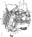
Fig. 2] Fig. 2 is a perspective view illustrating the disposition structure of intake pipes, fuel system components, a purge control valve of the engine. - [
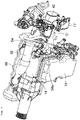
Fig. 3] Fig. 3 is a perspective view illustrating intake system components of the engine. - [
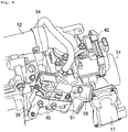
Fig. 4] Fig. 4 is a perspective view illustrating the mount structure of the purge control valve, in which a part thereof is indicated by a cross section. - [
Fig. 5] Fig. 5 is a perspective view illustrating the mount structure of the purge control valve. - [
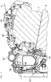
Fig. 6] Fig. 6 is a side view illustrating an upper portion of the engine, in which a part thereof is indicated by a cross section. - Embodiments for achieving the present invention will be described below with reference to the drawings.
- Description of the preferable embodiments below is only an example and does not intend to limit the present invention, an object to which the present invention has been applied, and the use of the present invention.
- In
Fig. 1 ,reference numeral 1 represents a gasoline engine for a vehicle and a plurality ofcylinders 3 is formed in acylinder block 2 thereof. Although only one of thecylinders 3 is illustrated inFig. 1 , theengine 1 is a multi-cylinder engine. Pistons 4 are slidably inserted into thecylinders 3. The pistons 4 are joined to acrankshaft 6 via connectingrods 5. The pistons 4 definecombustion chambers 8 together with thecylinders 3 and acylinder head 7. A direct-injectionfuel injection valve 11 and anignition plug 12 are attached to thecylinder head 7 for each of thecylinders 3. - In an
intake passage 15 of theengine 1, anair cleaner 16, athrottle valve 17, asupercharger 18, anintercooler 19, and asurge tank 21 are disposed in this order from the upstream to the downstream. The portion of theintake passage 15 downstream from thesurge tank 21 is formed by an intake manifold and the downstream end of an independent passage that branches for each of thecylinders 3 is connected to aninlet 22 of each of thecylinders 3. - In this example, the
supercharger 18 is a mechanical supercharger driven by theengine 1. The type of the mechanical supercharger may be, for example, root type, lysholm type, or centrifugal type, although the invention is not limited to these types. - In an
exhaust passage 25 of theengine 1, an exhaust gas purification system having one ormore catalyst converter 26 is provided. Thecatalyst converter 26 includes a three-way catalyst. It should be noted here that the exhaust gas purification system is not limited to one including only a three-way catalyst. The upstream end part of theexhaust passage 25 is formed by an exhaust air manifold and the upstream end of an independent passage that branches for each of thecylinders 3 is connected to anoutlet 27 of each of thecylinders 3. - The
intake passage 15 is connected to theexhaust passage 25 via an EGRpassage 31 that forms an external EGR system. The EGRpassage 31 returns a part of burnt gas from theexhaust passage 25 to theintake passage 15. The upstream end of the EGRpassage 52 is connected to a portion of theexhaust passage 25 downstream from thecatalyst converter 26. The downstream end of the EGRpassage 31 is connected to a portion of theintake passage 15 upstream from thesupercharger 18. In the EGRpassage 31, a water-cooledEGR cooler 32 that cools burnt gas and anEGR valve 33 that adjusts the backflow amount of burnt gas are disposed. - A fuel supply system 35 is connected to the
fuel injection valve 11. The fuel supply system 35 includes afuel supply path 37 that connects thefuel injection valve 11 and afuel tank 36 to each other. In thefuel supply path 37, afuel pump 38 and a common rail (fuel rail) 39 are provided. In this structural example, thefuel pump 38 is of plunger type that is driven by thecrankshaft 6. Thecommon rail 39 stores, at a high fuel pressure, the fuel pumped from thefuel pump 38. - A
bypass passage 41 bypasses thesupercharger 18 and theintercooler 19 is connected to theintake passage 15. That is, the upstream end of thebypass passage 41 is connected to a portion of theintake passage 15 between thethrottle valve 17 and thesupercharger 18 and the downstream end of thebypass passage 41 is connected to thesurge tank 21. Thebypass passage 41 is provided with abypass valve 42 that adjusts the passage opening thereof. - One end of a purge passage 43 through which evaporated fuel (evaporated gas) generated in the
fuel tank 36 is released to theintake passage 15 is connected to thefuel tank 36. The other end of this purge passage 43 is connected to a portion of theintake passage 15 upstream from thesupercharger 18 and downstream from the upstream end of thebypass passage 41. In the purge passage 43, acanister 44 that absorbs and stores the evaporated fuel and apurge control valve 45 that adjusts the supply amount (to the intake passage 15) of the evaporated fuel absorbed by thecanister 44 are provided. An outsideair introduction passage 46 through which outside air is introduced is connected to thecanister 44. Thisair release passage 46 is provided with an outsideair introduction valve 47 that controls the introduction amount of outside air to thecanister 44. - As illustrated in
Fig. 2 , theengine 1 is a front intake rear exhaust engine and is provided with a bypassair intake pipe 52 and a mainair intake pipe 51 constituting a portion of theintake passage 15 downstream from thethrottle valve 17 on the front side in a front-rear direction of the vehicle. Thepurge control valve 45 is connected to the mainair intake pipe 51. Thecommon rail 39 is disposed on thecylinder head 7 andfuel supply pipes 53 branching from thecommon rail 39 are connected to thefuel injection valves 11 of the cylinders illustrated inFig. 1 . - As illustrated in
Fig. 3 , the mainair intake pipe 51 extends in a cylinder array direction from one end side in the cylinder array direction toward the middle side on the side portion of theengine 1 and the downstream end thereof is connected to thesupercharger 18 disposed in the middle portion in the cylinder array direction. The bypassair intake pipe 52 branches from the mainair intake pipe 51 on the one end side in the cylinder array direction and extends toward the middle side in the cylinder array direction above the mainair intake pipe 51 and thesupercharger 18 so as to bypass thesupercharger 18 to form thebypass passage 41. The downstream portion of the bypassair intake pipe 52 is bifurcated and connected to anintake manifold 50. - A
connection portion 54 having aconnection port 54a to which thepurge control valve 45 is connected is provided in a portion of the mainair intake pipe 51 downstream from the branch portion of the bypassair intake pipe 52. - As illustrated in
Fig. 4 , theconnection portion 54 is provided on the side portion of the upper end portion of the mainair intake pipe 51. Anfuel vapor inlet 55 is opened in the mainair intake pipe 51 in the back portion of the connection port of theconnection portion 54. Thepurge control valve 45 is provided with an evaporated fueloutflow connection pipe 57 that projects from a valve main body 56. Theoutflow connection pipe 57 is inserted into theconnection port 54a of theconnection portion 54 of the mainair intake pipe 51. That is, thepurge control valve 45 is directly connected to the mainair intake pipe 51 without intervention of a purge hose. As is clear fromFig. 4 , the bypassair intake pipe 52 branches from a portion of the mainair intake pipe 51 upstream from theconnection portion 54 of thepurge control valve 45, that is, a portion upstream from thefuel vapor inlet 55. It should be noted here that the internal mechanism of the valve body of thepurge control valve 45 is omitted by hatching it inFig. 4 . - As illustrated in
Fig. 5 , abracket 59 for supporting thepurge control valve 45 and a resonator (muffler) 58 is fixed to thecylinder head 7. Theresonator 58 reduces the operation noise of thepurge control valve 45. Ahose connection pipe 61 for inflow of evaporated fuel branches from a pipe connecting thepurge control valve 45 and theresonator 58. A hose for evaporated fuel extending from thecanister 44 is connected to thehose connection pipe 61. - As is clear from
Fig. 2 , in the above structure, thepurge control valve 45 is, in vehicle front view, present on a side in front of theintake pipes fuel system components purge control valve 45 with theintake pipes - As illustrated in
Fig. 6 , in side view of theengine 1, theintake pipes purge control valve 45 and thefuel system parts purge control valve 45 faces thefuel system parts intake pipes intake pipes purge control valve 45 and thefuel system components air intake pipe 52 is present above the mainair intake pipe 51 and present between thepurge control valve 45 and thefuel system components cylinder block 2 and thecylinder head 7 are omitted by hatching them inFig. 6 . - Since the
purge control valve 45 is directly connected to the mainair intake pipe 51 without intervention of an evaporated fuel hose as described above, evaporated fuel is responsively supplied to theintake passage 15 by the operation of thepurge control valve 45. - Although the
purge control valve 45 is directly connected to the mainair intake pipe 51 in the embodiment described above, the present invention does not exclude connection of thepurge control valve 45 to the mainair intake pipe 51 via an evaporated fuel hose. Also in the case in which both are connected via an evaporated fuel hose, since the evaporated fuel hose can be shortened when thepurge control valve 45 is disposed in front of the mainair intake pipe 51, the response of purging is high. - In addition, since the
fuel vapor inlet 55 is opened in a portion of the mainair intake pipe 51 upstream from thesupercharger 18 and the bypassair intake pipe 52 branches from a portion of the mainair intake pipe 51 upstream from thefuel vapor inlet 55, the suction force of intake air by thesupercharger 18 can be used to purge the evaporated fuel when thesupercharger 18 operates. Therefore, desired purge efficiency can be obtained even when thethrottle valve 17 is fully open. - Even when a force is applied to the
purge control valve 45 during the front collision of the vehicle so as to remove thepurge control valve 45 from thebracket 59 and throw thepurge control valve 45 backward, since theintake pipes fuel system components purge control valve 45 can be prevented from colliding with thefuel system components fuel system components air intake pipe 52 is provided so as to project upward as viewed from thepurge control valve 45, even when thepurge control valve 52 thrown obliquely upward during the collision, thepurge control valve 52 can be prevented from colliding with thefuel system components purge control valve 52 hits the bypassair intake pipe 52. - In addition, even when the
purge control valve 45 is pushed toward thefuel system components intake pipes intake pipes fuel system components - Although the embodiment described above relates to a front intake rear exhaust horizontal engine, the intake pipes, the fuel system components, and the purge control valve may have the same disposition structure as in the embodiment described above from the viewpoint of protection of the fuel system components during a side collision of the vehicle also in a vertical engine in which the cylinder array direction is aligned with the vehicle front-rear direction. That is, in vehicle side view, the purge control valve is disposed on a side in front of the intake pipes, the fuel system components are disposed on the side opposite to the purge control valve with the intake pipes arranged inbetween, and the intake pipes are present between the purge control valve and the fuel system components.
- Since such a disposition structure is adopted, even if the purge control valve is removed during a side collision of the vehicle from the side on which the purge control valve is installed, the intake pipes prevent the purge control valve from colliding with the fuel system components. Alternatively, even if the purge control valve is pushed toward the fuel system components due to the collision of the vehicle, the intake pipes function as cushions and prevent the fuel system components from being damaged.
-
- 1:
- engine
- 7:
- cylinder head
- 17:
- throttle valve
- 18:
- supercharger
- 39:
- common rail (fuel rail)
- 44:
- canister
- 45:
- purge control valve
- 51:
- main air intake pipe
- 52:
- bypass air intake pipe
- 53:
- fuel supply pipe
- 55:
- fuel vapor inlet
- 56:
- valve body
- 57:
- evaporated fuel outflow connection pipe
Claims (5)
- An engine comprising:a fuel system component provided on a cylinder head;a purge control valve that controls an amount of evaporated fuel to be purged from a canister to a portion of an intake passage downstream from a throttle valve; andan intake pipe that forms the portion of the intake passage downstream from the throttle valve, the intake pipe extending in a cylinder array direction,wherein the purge control valve is, in vehicle front view or vehicle side view, disposed on a side in front of the intake pipe and the fuel system component is disposed on a side opposite to the purge control valve with the intake pipe arranged inbetween.
- The engine according to claim 1,
wherein, the intake pipe that forms the portion of the intake passage downstream from the throttle valve includes a main air intake pipe that is connected to a supercharger and extends in the cylinder array direction and a bypass air intake pipe that branches from the main air intake pipe so as to bypass the supercharger and extends in the cylinder array direction,
the bypass air intake pipe extends in the cylinder array direction above the main air intake pipe, and
the purge control valve is provided so as to purge the evaporated fuel into the main air intake pipe. - The engine according to claim 2,
wherein an fuel vapor inlet related to the purge control valve is opened in a portion of the main air intake pipe upstream from the supercharger and
the bypass air intake pipe branches from a portion of the main air intake pipe upstream from the fuel vapor inlet and is connected to a portion of the main air intake pipe downstream from the supercharger. - The engine according to any one of claims 1 to 3,
wherein the fuel vapor inlet is opened in an upper portion of the intake pipe that forms the portion of the intake passage downstream from the throttle valve. - The engine according to any one of claims 1 to 4,
wherein the purge control valve has an outflow connection pipe projecting from a valve body and the outflow connection pipe is directly connected to the intake pipe that forms the portion of the intake passage downstream from the throttle valve.
Applications Claiming Priority (2)
| Application Number | Priority Date | Filing Date | Title |
|---|---|---|---|
| JP2017056473A JP6436179B2 (en) | 2017-03-22 | 2017-03-22 | engine |
| PCT/JP2018/004468 WO2018173537A1 (en) | 2017-03-22 | 2018-02-08 | Engine |
Publications (3)
| Publication Number | Publication Date |
|---|---|
| EP3578795A1 true EP3578795A1 (en) | 2019-12-11 |
| EP3578795A4 EP3578795A4 (en) | 2020-03-11 |
| EP3578795B1 EP3578795B1 (en) | 2022-01-12 |
Family
ID=63585346
Family Applications (1)
| Application Number | Title | Priority Date | Filing Date |
|---|---|---|---|
| EP18770616.3A Active EP3578795B1 (en) | 2017-03-22 | 2018-02-08 | Engine |
Country Status (5)
| Country | Link |
|---|---|
| US (1) | US10844809B2 (en) |
| EP (1) | EP3578795B1 (en) |
| JP (1) | JP6436179B2 (en) |
| CN (1) | CN110382854B (en) |
| WO (1) | WO2018173537A1 (en) |
Families Citing this family (3)
| Publication number | Priority date | Publication date | Assignee | Title |
|---|---|---|---|---|
| JP2020012429A (en) * | 2018-07-19 | 2020-01-23 | マツダ株式会社 | Evaporative fuel processor for engine |
| JP7107181B2 (en) * | 2018-11-13 | 2022-07-27 | トヨタ自動車株式会社 | internal combustion engine |
| JP7056547B2 (en) * | 2018-12-28 | 2022-04-19 | トヨタ自動車株式会社 | Hybrid vehicle |
Family Cites Families (17)
| Publication number | Priority date | Publication date | Assignee | Title |
|---|---|---|---|---|
| JP3116556B2 (en) * | 1992-06-08 | 2000-12-11 | 株式会社デンソー | Airtightness check device for fuel tank system of internal combustion engine |
| JP3368693B2 (en) * | 1994-10-25 | 2003-01-20 | トヨタ自動車株式会社 | Evaporative fuel treatment system for internal combustion engine |
| JPH11210573A (en) * | 1998-01-30 | 1999-08-03 | Suzuki Motor Corp | Intake structure of internal combustion engine |
| JP3815333B2 (en) * | 2002-01-10 | 2006-08-30 | 日産自動車株式会社 | Intake device for internal combustion engine |
| JP2005090429A (en) * | 2003-09-19 | 2005-04-07 | Suzuki Motor Corp | Evaporative fuel processing device for vehicle |
| JP4581747B2 (en) * | 2005-03-01 | 2010-11-17 | マツダ株式会社 | Intake device for vehicle engine |
| US7320301B1 (en) * | 2007-04-04 | 2008-01-22 | Gm Global Technology Operations, Inc. | Clock and anchor pipe fitting and method |
| US20110277716A1 (en) * | 2010-05-17 | 2011-11-17 | Gm Global Technology Operations, Inc. | Intake Manifold for an Internal Combustion Engine |
| US8567365B2 (en) * | 2010-06-25 | 2013-10-29 | Ford Global Technologies, Llc | Vacuum port having a flow disruptor |
| JP5870900B2 (en) * | 2012-10-31 | 2016-03-01 | トヨタ自動車株式会社 | Intake manifold |
| WO2014068825A1 (en) * | 2012-10-31 | 2014-05-08 | トヨタ自動車株式会社 | Intake manifold |
| JP6142855B2 (en) * | 2014-09-03 | 2017-06-07 | マツダ株式会社 | Engine intake manifold structure |
| JP6146399B2 (en) * | 2014-11-27 | 2017-06-14 | マツダ株式会社 | Engine intake system |
| US9574509B2 (en) * | 2014-12-17 | 2017-02-21 | Ford Global Technologies, Llc | System and method for exhaust gas recirculation estimation with two intake oxygen sensors |
| JP2016125467A (en) * | 2015-01-08 | 2016-07-11 | アイシン精機株式会社 | Suction device of internal combustion engine |
| US9651003B2 (en) * | 2015-01-09 | 2017-05-16 | Ford Global Technologies, Llc | System and method for improving canister purging |
| JP2016133114A (en) | 2015-01-22 | 2016-07-25 | トヨタ自動車株式会社 | Internal combustion engine with variable resonator |
-
2017
- 2017-03-22 JP JP2017056473A patent/JP6436179B2/en active Active
-
2018
- 2018-02-08 EP EP18770616.3A patent/EP3578795B1/en active Active
- 2018-02-08 US US16/490,455 patent/US10844809B2/en active Active
- 2018-02-08 CN CN201880015525.9A patent/CN110382854B/en not_active Expired - Fee Related
- 2018-02-08 WO PCT/JP2018/004468 patent/WO2018173537A1/en not_active Ceased
Also Published As
| Publication number | Publication date |
|---|---|
| US20200018264A1 (en) | 2020-01-16 |
| CN110382854B (en) | 2021-06-22 |
| JP6436179B2 (en) | 2018-12-12 |
| EP3578795A4 (en) | 2020-03-11 |
| WO2018173537A1 (en) | 2018-09-27 |
| EP3578795B1 (en) | 2022-01-12 |
| US10844809B2 (en) | 2020-11-24 |
| JP2018159314A (en) | 2018-10-11 |
| CN110382854A (en) | 2019-10-25 |
Similar Documents
| Publication | Publication Date | Title |
|---|---|---|
| US10196992B2 (en) | Engine control device | |
| KR101886091B1 (en) | Fuel vapor purging system | |
| KR102239402B1 (en) | Engine unit | |
| KR102727896B1 (en) | Purge system for fuel vaporized gas of vehicle | |
| JP6112046B2 (en) | Evaporative fuel processing device for supercharged engine | |
| US10844809B2 (en) | Engine | |
| WO2018173406A1 (en) | Engine device | |
| JP6183584B2 (en) | Vehicle internal combustion engine | |
| KR20220025278A (en) | Engine device | |
| CN101326068A (en) | Internal combustion engine with turbocharger | |
| CN109578157B (en) | Engine control device | |
| JP4174939B2 (en) | Fuel supply device for in-cylinder injection engine | |
| CN109790777A (en) | The intake channel of turbocharged engine constructs | |
| JP4581747B2 (en) | Intake device for vehicle engine | |
| JP4206781B2 (en) | Exhaust manifold structure of engine with exhaust supercharger | |
| JP2023001225A (en) | engine device | |
| JP4178703B2 (en) | Engine fuel supply system | |
| JP2024531742A (en) | Internal combustion engines for motor vehicles, in particular for automobiles | |
| JP7184026B2 (en) | diesel engine | |
| CN105298609B (en) | Exhaust Aftertreatment System | |
| JPH03260368A (en) | Intake device of engine | |
| JP2023022131A (en) | engine device | |
| JP2012197719A (en) | Structure of exhaust gas recirculation device | |
| JP2022012278A (en) | Support structure of intercooler | |
| JP2007071150A (en) | Intake device for turbocharged engine |
Legal Events
| Date | Code | Title | Description |
|---|---|---|---|
| STAA | Information on the status of an ep patent application or granted ep patent |
Free format text: STATUS: THE INTERNATIONAL PUBLICATION HAS BEEN MADE |
|
| PUAI | Public reference made under article 153(3) epc to a published international application that has entered the european phase |
Free format text: ORIGINAL CODE: 0009012 |
|
| STAA | Information on the status of an ep patent application or granted ep patent |
Free format text: STATUS: REQUEST FOR EXAMINATION WAS MADE |
|
| 17P | Request for examination filed |
Effective date: 20190905 |
|
| AK | Designated contracting states |
Kind code of ref document: A1 Designated state(s): AL AT BE BG CH CY CZ DE DK EE ES FI FR GB GR HR HU IE IS IT LI LT LU LV MC MK MT NL NO PL PT RO RS SE SI SK SM TR |
|
| AX | Request for extension of the european patent |
Extension state: BA ME |
|
| A4 | Supplementary search report drawn up and despatched |
Effective date: 20200212 |
|
| RIC1 | Information provided on ipc code assigned before grant |
Ipc: F02M 25/08 20060101AFI20200206BHEP Ipc: F02B 77/08 20060101ALI20200206BHEP Ipc: F02M 35/10 20060101ALI20200206BHEP |
|
| DAV | Request for validation of the european patent (deleted) | ||
| DAX | Request for extension of the european patent (deleted) | ||
| STAA | Information on the status of an ep patent application or granted ep patent |
Free format text: STATUS: EXAMINATION IS IN PROGRESS |
|
| 17Q | First examination report despatched |
Effective date: 20200929 |
|
| GRAP | Despatch of communication of intention to grant a patent |
Free format text: ORIGINAL CODE: EPIDOSNIGR1 |
|
| STAA | Information on the status of an ep patent application or granted ep patent |
Free format text: STATUS: GRANT OF PATENT IS INTENDED |
|
| INTG | Intention to grant announced |
Effective date: 20210804 |
|
| GRAS | Grant fee paid |
Free format text: ORIGINAL CODE: EPIDOSNIGR3 |
|
| GRAA | (expected) grant |
Free format text: ORIGINAL CODE: 0009210 |
|
| STAA | Information on the status of an ep patent application or granted ep patent |
Free format text: STATUS: THE PATENT HAS BEEN GRANTED |
|
| AK | Designated contracting states |
Kind code of ref document: B1 Designated state(s): AL AT BE BG CH CY CZ DE DK EE ES FI FR GB GR HR HU IE IS IT LI LT LU LV MC MK MT NL NO PL PT RO RS SE SI SK SM TR |
|
| REG | Reference to a national code |
Ref country code: GB Ref legal event code: FG4D |
|
| REG | Reference to a national code |
Ref country code: CH Ref legal event code: EP |
|
| REG | Reference to a national code |
Ref country code: DE Ref legal event code: R096 Ref document number: 602018029558 Country of ref document: DE |
|
| REG | Reference to a national code |
Ref country code: IE Ref legal event code: FG4D |
|
| REG | Reference to a national code |
Ref country code: AT Ref legal event code: REF Ref document number: 1462548 Country of ref document: AT Kind code of ref document: T Effective date: 20220215 |
|
| REG | Reference to a national code |
Ref country code: LT Ref legal event code: MG9D |
|
| REG | Reference to a national code |
Ref country code: NL Ref legal event code: MP Effective date: 20220112 |
|
| REG | Reference to a national code |
Ref country code: AT Ref legal event code: MK05 Ref document number: 1462548 Country of ref document: AT Kind code of ref document: T Effective date: 20220112 |
|
| PG25 | Lapsed in a contracting state [announced via postgrant information from national office to epo] |
Ref country code: NL Free format text: LAPSE BECAUSE OF FAILURE TO SUBMIT A TRANSLATION OF THE DESCRIPTION OR TO PAY THE FEE WITHIN THE PRESCRIBED TIME-LIMIT Effective date: 20220112 |
|
| PG25 | Lapsed in a contracting state [announced via postgrant information from national office to epo] |
Ref country code: SE Free format text: LAPSE BECAUSE OF FAILURE TO SUBMIT A TRANSLATION OF THE DESCRIPTION OR TO PAY THE FEE WITHIN THE PRESCRIBED TIME-LIMIT Effective date: 20220112 Ref country code: RS Free format text: LAPSE BECAUSE OF FAILURE TO SUBMIT A TRANSLATION OF THE DESCRIPTION OR TO PAY THE FEE WITHIN THE PRESCRIBED TIME-LIMIT Effective date: 20220112 Ref country code: PT Free format text: LAPSE BECAUSE OF FAILURE TO SUBMIT A TRANSLATION OF THE DESCRIPTION OR TO PAY THE FEE WITHIN THE PRESCRIBED TIME-LIMIT Effective date: 20220512 Ref country code: NO Free format text: LAPSE BECAUSE OF FAILURE TO SUBMIT A TRANSLATION OF THE DESCRIPTION OR TO PAY THE FEE WITHIN THE PRESCRIBED TIME-LIMIT Effective date: 20220412 Ref country code: LT Free format text: LAPSE BECAUSE OF FAILURE TO SUBMIT A TRANSLATION OF THE DESCRIPTION OR TO PAY THE FEE WITHIN THE PRESCRIBED TIME-LIMIT Effective date: 20220112 Ref country code: HR Free format text: LAPSE BECAUSE OF FAILURE TO SUBMIT A TRANSLATION OF THE DESCRIPTION OR TO PAY THE FEE WITHIN THE PRESCRIBED TIME-LIMIT Effective date: 20220112 Ref country code: ES Free format text: LAPSE BECAUSE OF FAILURE TO SUBMIT A TRANSLATION OF THE DESCRIPTION OR TO PAY THE FEE WITHIN THE PRESCRIBED TIME-LIMIT Effective date: 20220112 Ref country code: BG Free format text: LAPSE BECAUSE OF FAILURE TO SUBMIT A TRANSLATION OF THE DESCRIPTION OR TO PAY THE FEE WITHIN THE PRESCRIBED TIME-LIMIT Effective date: 20220412 |
|
| PG25 | Lapsed in a contracting state [announced via postgrant information from national office to epo] |
Ref country code: PL Free format text: LAPSE BECAUSE OF FAILURE TO SUBMIT A TRANSLATION OF THE DESCRIPTION OR TO PAY THE FEE WITHIN THE PRESCRIBED TIME-LIMIT Effective date: 20220112 Ref country code: LV Free format text: LAPSE BECAUSE OF FAILURE TO SUBMIT A TRANSLATION OF THE DESCRIPTION OR TO PAY THE FEE WITHIN THE PRESCRIBED TIME-LIMIT Effective date: 20220112 Ref country code: GR Free format text: LAPSE BECAUSE OF FAILURE TO SUBMIT A TRANSLATION OF THE DESCRIPTION OR TO PAY THE FEE WITHIN THE PRESCRIBED TIME-LIMIT Effective date: 20220413 Ref country code: FI Free format text: LAPSE BECAUSE OF FAILURE TO SUBMIT A TRANSLATION OF THE DESCRIPTION OR TO PAY THE FEE WITHIN THE PRESCRIBED TIME-LIMIT Effective date: 20220112 Ref country code: AT Free format text: LAPSE BECAUSE OF FAILURE TO SUBMIT A TRANSLATION OF THE DESCRIPTION OR TO PAY THE FEE WITHIN THE PRESCRIBED TIME-LIMIT Effective date: 20220112 |
|
| PG25 | Lapsed in a contracting state [announced via postgrant information from national office to epo] |
Ref country code: IS Free format text: LAPSE BECAUSE OF FAILURE TO SUBMIT A TRANSLATION OF THE DESCRIPTION OR TO PAY THE FEE WITHIN THE PRESCRIBED TIME-LIMIT Effective date: 20220512 |
|
| REG | Reference to a national code |
Ref country code: DE Ref legal event code: R097 Ref document number: 602018029558 Country of ref document: DE |
|
| REG | Reference to a national code |
Ref country code: CH Ref legal event code: PL |
|
| REG | Reference to a national code |
Ref country code: BE Ref legal event code: MM Effective date: 20220228 |
|
| PG25 | Lapsed in a contracting state [announced via postgrant information from national office to epo] |
Ref country code: SM Free format text: LAPSE BECAUSE OF FAILURE TO SUBMIT A TRANSLATION OF THE DESCRIPTION OR TO PAY THE FEE WITHIN THE PRESCRIBED TIME-LIMIT Effective date: 20220112 Ref country code: SK Free format text: LAPSE BECAUSE OF FAILURE TO SUBMIT A TRANSLATION OF THE DESCRIPTION OR TO PAY THE FEE WITHIN THE PRESCRIBED TIME-LIMIT Effective date: 20220112 Ref country code: RO Free format text: LAPSE BECAUSE OF FAILURE TO SUBMIT A TRANSLATION OF THE DESCRIPTION OR TO PAY THE FEE WITHIN THE PRESCRIBED TIME-LIMIT Effective date: 20220112 Ref country code: MC Free format text: LAPSE BECAUSE OF FAILURE TO SUBMIT A TRANSLATION OF THE DESCRIPTION OR TO PAY THE FEE WITHIN THE PRESCRIBED TIME-LIMIT Effective date: 20220112 Ref country code: LU Free format text: LAPSE BECAUSE OF NON-PAYMENT OF DUE FEES Effective date: 20220208 Ref country code: EE Free format text: LAPSE BECAUSE OF FAILURE TO SUBMIT A TRANSLATION OF THE DESCRIPTION OR TO PAY THE FEE WITHIN THE PRESCRIBED TIME-LIMIT Effective date: 20220112 Ref country code: DK Free format text: LAPSE BECAUSE OF FAILURE TO SUBMIT A TRANSLATION OF THE DESCRIPTION OR TO PAY THE FEE WITHIN THE PRESCRIBED TIME-LIMIT Effective date: 20220112 Ref country code: CZ Free format text: LAPSE BECAUSE OF FAILURE TO SUBMIT A TRANSLATION OF THE DESCRIPTION OR TO PAY THE FEE WITHIN THE PRESCRIBED TIME-LIMIT Effective date: 20220112 |
|
| PLBE | No opposition filed within time limit |
Free format text: ORIGINAL CODE: 0009261 |
|
| STAA | Information on the status of an ep patent application or granted ep patent |
Free format text: STATUS: NO OPPOSITION FILED WITHIN TIME LIMIT |
|
| PG25 | Lapsed in a contracting state [announced via postgrant information from national office to epo] |
Ref country code: AL Free format text: LAPSE BECAUSE OF FAILURE TO SUBMIT A TRANSLATION OF THE DESCRIPTION OR TO PAY THE FEE WITHIN THE PRESCRIBED TIME-LIMIT Effective date: 20220112 |
|
| 26N | No opposition filed |
Effective date: 20221013 |
|
| GBPC | Gb: european patent ceased through non-payment of renewal fee |
Effective date: 20220412 |
|
| PG25 | Lapsed in a contracting state [announced via postgrant information from national office to epo] |
Ref country code: LI Free format text: LAPSE BECAUSE OF NON-PAYMENT OF DUE FEES Effective date: 20220228 Ref country code: IE Free format text: LAPSE BECAUSE OF NON-PAYMENT OF DUE FEES Effective date: 20220208 Ref country code: GB Free format text: LAPSE BECAUSE OF NON-PAYMENT OF DUE FEES Effective date: 20220412 Ref country code: FR Free format text: LAPSE BECAUSE OF NON-PAYMENT OF DUE FEES Effective date: 20220312 Ref country code: CH Free format text: LAPSE BECAUSE OF NON-PAYMENT OF DUE FEES Effective date: 20220228 |
|
| PG25 | Lapsed in a contracting state [announced via postgrant information from national office to epo] |
Ref country code: SI Free format text: LAPSE BECAUSE OF FAILURE TO SUBMIT A TRANSLATION OF THE DESCRIPTION OR TO PAY THE FEE WITHIN THE PRESCRIBED TIME-LIMIT Effective date: 20220112 Ref country code: BE Free format text: LAPSE BECAUSE OF NON-PAYMENT OF DUE FEES Effective date: 20220228 |
|
| PG25 | Lapsed in a contracting state [announced via postgrant information from national office to epo] |
Ref country code: IT Free format text: LAPSE BECAUSE OF FAILURE TO SUBMIT A TRANSLATION OF THE DESCRIPTION OR TO PAY THE FEE WITHIN THE PRESCRIBED TIME-LIMIT Effective date: 20220112 |
|
| PG25 | Lapsed in a contracting state [announced via postgrant information from national office to epo] |
Ref country code: MK Free format text: LAPSE BECAUSE OF FAILURE TO SUBMIT A TRANSLATION OF THE DESCRIPTION OR TO PAY THE FEE WITHIN THE PRESCRIBED TIME-LIMIT Effective date: 20220112 Ref country code: CY Free format text: LAPSE BECAUSE OF FAILURE TO SUBMIT A TRANSLATION OF THE DESCRIPTION OR TO PAY THE FEE WITHIN THE PRESCRIBED TIME-LIMIT Effective date: 20220112 |
|
| PG25 | Lapsed in a contracting state [announced via postgrant information from national office to epo] |
Ref country code: HU Free format text: LAPSE BECAUSE OF FAILURE TO SUBMIT A TRANSLATION OF THE DESCRIPTION OR TO PAY THE FEE WITHIN THE PRESCRIBED TIME-LIMIT; INVALID AB INITIO Effective date: 20180208 |
|
| PG25 | Lapsed in a contracting state [announced via postgrant information from national office to epo] |
Ref country code: MT Free format text: LAPSE BECAUSE OF FAILURE TO SUBMIT A TRANSLATION OF THE DESCRIPTION OR TO PAY THE FEE WITHIN THE PRESCRIBED TIME-LIMIT Effective date: 20220112 |
|
| PG25 | Lapsed in a contracting state [announced via postgrant information from national office to epo] |
Ref country code: TR Free format text: LAPSE BECAUSE OF FAILURE TO SUBMIT A TRANSLATION OF THE DESCRIPTION OR TO PAY THE FEE WITHIN THE PRESCRIBED TIME-LIMIT Effective date: 20220112 |
|
| PGFP | Annual fee paid to national office [announced via postgrant information from national office to epo] |
Ref country code: DE Payment date: 20251230 Year of fee payment: 9 |