EP3578784A1 - Petrol/diesel and lpg fuel supply system for internal combustion engines - Google Patents
Petrol/diesel and lpg fuel supply system for internal combustion engines Download PDFInfo
- Publication number
- EP3578784A1 EP3578784A1 EP19460028.4A EP19460028A EP3578784A1 EP 3578784 A1 EP3578784 A1 EP 3578784A1 EP 19460028 A EP19460028 A EP 19460028A EP 3578784 A1 EP3578784 A1 EP 3578784A1
- Authority
- EP
- European Patent Office
- Prior art keywords
- lpg
- petrol
- fuel
- pressure pump
- diesel oil
- Prior art date
- Legal status (The legal status is an assumption and is not a legal conclusion. Google has not performed a legal analysis and makes no representation as to the accuracy of the status listed.)
- Granted
Links
Images
Classifications
-
- F—MECHANICAL ENGINEERING; LIGHTING; HEATING; WEAPONS; BLASTING
- F02—COMBUSTION ENGINES; HOT-GAS OR COMBUSTION-PRODUCT ENGINE PLANTS
- F02D—CONTROLLING COMBUSTION ENGINES
- F02D19/00—Controlling engines characterised by their use of non-liquid fuels, pluralities of fuels, or non-fuel substances added to the combustible mixtures
- F02D19/06—Controlling engines characterised by their use of non-liquid fuels, pluralities of fuels, or non-fuel substances added to the combustible mixtures peculiar to engines working with pluralities of fuels, e.g. alternatively with light and heavy fuel oil, other than engines indifferent to the fuel consumed
- F02D19/0663—Details on the fuel supply system, e.g. tanks, valves, pipes, pumps, rails, injectors or mixers
- F02D19/0665—Tanks, e.g. multiple tanks
-
- F—MECHANICAL ENGINEERING; LIGHTING; HEATING; WEAPONS; BLASTING
- F02—COMBUSTION ENGINES; HOT-GAS OR COMBUSTION-PRODUCT ENGINE PLANTS
- F02D—CONTROLLING COMBUSTION ENGINES
- F02D19/00—Controlling engines characterised by their use of non-liquid fuels, pluralities of fuels, or non-fuel substances added to the combustible mixtures
- F02D19/06—Controlling engines characterised by their use of non-liquid fuels, pluralities of fuels, or non-fuel substances added to the combustible mixtures peculiar to engines working with pluralities of fuels, e.g. alternatively with light and heavy fuel oil, other than engines indifferent to the fuel consumed
- F02D19/0602—Control of components of the fuel supply system
- F02D19/0613—Switch-over from one fuel to another
- F02D19/0615—Switch-over from one fuel to another being initiated by automatic means, e.g. based on engine or vehicle operating conditions
-
- F—MECHANICAL ENGINEERING; LIGHTING; HEATING; WEAPONS; BLASTING
- F02—COMBUSTION ENGINES; HOT-GAS OR COMBUSTION-PRODUCT ENGINE PLANTS
- F02D—CONTROLLING COMBUSTION ENGINES
- F02D19/00—Controlling engines characterised by their use of non-liquid fuels, pluralities of fuels, or non-fuel substances added to the combustible mixtures
- F02D19/06—Controlling engines characterised by their use of non-liquid fuels, pluralities of fuels, or non-fuel substances added to the combustible mixtures peculiar to engines working with pluralities of fuels, e.g. alternatively with light and heavy fuel oil, other than engines indifferent to the fuel consumed
- F02D19/0639—Controlling engines characterised by their use of non-liquid fuels, pluralities of fuels, or non-fuel substances added to the combustible mixtures peculiar to engines working with pluralities of fuels, e.g. alternatively with light and heavy fuel oil, other than engines indifferent to the fuel consumed characterised by the type of fuels
- F02D19/0642—Controlling engines characterised by their use of non-liquid fuels, pluralities of fuels, or non-fuel substances added to the combustible mixtures peculiar to engines working with pluralities of fuels, e.g. alternatively with light and heavy fuel oil, other than engines indifferent to the fuel consumed characterised by the type of fuels at least one fuel being gaseous, the other fuels being gaseous or liquid at standard conditions
- F02D19/0647—Controlling engines characterised by their use of non-liquid fuels, pluralities of fuels, or non-fuel substances added to the combustible mixtures peculiar to engines working with pluralities of fuels, e.g. alternatively with light and heavy fuel oil, other than engines indifferent to the fuel consumed characterised by the type of fuels at least one fuel being gaseous, the other fuels being gaseous or liquid at standard conditions the gaseous fuel being liquefied petroleum gas [LPG], liquefied natural gas [LNG], compressed natural gas [CNG] or dimethyl ether [DME]
-
- F—MECHANICAL ENGINEERING; LIGHTING; HEATING; WEAPONS; BLASTING
- F02—COMBUSTION ENGINES; HOT-GAS OR COMBUSTION-PRODUCT ENGINE PLANTS
- F02D—CONTROLLING COMBUSTION ENGINES
- F02D19/00—Controlling engines characterised by their use of non-liquid fuels, pluralities of fuels, or non-fuel substances added to the combustible mixtures
- F02D19/06—Controlling engines characterised by their use of non-liquid fuels, pluralities of fuels, or non-fuel substances added to the combustible mixtures peculiar to engines working with pluralities of fuels, e.g. alternatively with light and heavy fuel oil, other than engines indifferent to the fuel consumed
- F02D19/0663—Details on the fuel supply system, e.g. tanks, valves, pipes, pumps, rails, injectors or mixers
- F02D19/0673—Valves; Pressure or flow regulators; Mixers
- F02D19/0676—Multi-way valves; Switch-over valves
-
- F—MECHANICAL ENGINEERING; LIGHTING; HEATING; WEAPONS; BLASTING
- F02—COMBUSTION ENGINES; HOT-GAS OR COMBUSTION-PRODUCT ENGINE PLANTS
- F02D—CONTROLLING COMBUSTION ENGINES
- F02D19/00—Controlling engines characterised by their use of non-liquid fuels, pluralities of fuels, or non-fuel substances added to the combustible mixtures
- F02D19/06—Controlling engines characterised by their use of non-liquid fuels, pluralities of fuels, or non-fuel substances added to the combustible mixtures peculiar to engines working with pluralities of fuels, e.g. alternatively with light and heavy fuel oil, other than engines indifferent to the fuel consumed
- F02D19/0663—Details on the fuel supply system, e.g. tanks, valves, pipes, pumps, rails, injectors or mixers
- F02D19/0684—High pressure fuel injection systems; Details on pumps, rails or the arrangement of valves in the fuel supply and return systems
-
- F—MECHANICAL ENGINEERING; LIGHTING; HEATING; WEAPONS; BLASTING
- F02—COMBUSTION ENGINES; HOT-GAS OR COMBUSTION-PRODUCT ENGINE PLANTS
- F02D—CONTROLLING COMBUSTION ENGINES
- F02D19/00—Controlling engines characterised by their use of non-liquid fuels, pluralities of fuels, or non-fuel substances added to the combustible mixtures
- F02D19/06—Controlling engines characterised by their use of non-liquid fuels, pluralities of fuels, or non-fuel substances added to the combustible mixtures peculiar to engines working with pluralities of fuels, e.g. alternatively with light and heavy fuel oil, other than engines indifferent to the fuel consumed
- F02D19/0663—Details on the fuel supply system, e.g. tanks, valves, pipes, pumps, rails, injectors or mixers
- F02D19/0686—Injectors
- F02D19/0694—Injectors operating with a plurality of fuels
-
- Y—GENERAL TAGGING OF NEW TECHNOLOGICAL DEVELOPMENTS; GENERAL TAGGING OF CROSS-SECTIONAL TECHNOLOGIES SPANNING OVER SEVERAL SECTIONS OF THE IPC; TECHNICAL SUBJECTS COVERED BY FORMER USPC CROSS-REFERENCE ART COLLECTIONS [XRACs] AND DIGESTS
- Y02—TECHNOLOGIES OR APPLICATIONS FOR MITIGATION OR ADAPTATION AGAINST CLIMATE CHANGE
- Y02T—CLIMATE CHANGE MITIGATION TECHNOLOGIES RELATED TO TRANSPORTATION
- Y02T10/00—Road transport of goods or passengers
- Y02T10/10—Internal combustion engine [ICE] based vehicles
- Y02T10/30—Use of alternative fuels, e.g. biofuels
Definitions
- the subject of the invention is a system of supplying combustion engines with fuel, alternately with petrol / diesel oil or LPG, especially engines with multi-point or direct injection.
- Polish invention No. PL222798 presents a system supplying combustion engines with fuels such as petrol/diesel oil and interchangeably LPG.
- This system consists of a pump feeding fuel to the high pressure pump and a multivalve controlling the change of fuel in the supply system.
- the LPG tank In the LPG tank there is a pump, ahead of which a fuel type switch is placed, from this pump the fuel is fed to the high pressure pump. Downstream the high pressure pump, which feeds fuel directly to the engine, on the return pipe connecting the high pressure pump with the LPG tank, a return valve is located which receives signals from the sensors measuring the fuel pressure and temperature. In a situation when LPG is in the supply system, the correct pressure and temperature are maintained.
- system supplying combustion engines with fuel alternately with petrol / diesel oil or LPG, is characterized in that in the LPG tank in a sealed glass isolated from the LPG tank a low pressure pump is placed, which at the input is equipped with elecrovalve as a fuel change switch from petrol / diesel oil to LPG, wherein the low pressure branch at the outlet of the high pressure pump feeding the engine is connected to the manifold of the small and big fuel circuit, in which the small circuit valve is connected to the inlet of the low pressure pump in a sealed glass and the big circuit valve is connected to the LPG tank, where the petrol / diesel oil is supplied to the inlet of the sealed glass via the electrovalve.
- Sealed glass is placed in the LPG tank via the cup, the sealed glass being the upper plate attached to the main plate of the cup.
- a non-return valve is mounted to block gas outflow from the LPG tank and on the LPG supply line to the low pressure pump a manual shut-off valve is installed.
- the system according to the invention makes it possible to quickly change the fuel supplying the engine, while protecting against mixing of fuels in the LPG tank, which will be explained in detail when describing an example of the system solution.
- the system supplying the engines with fuel, alternately with petrol /diesel oil LPG, is shown in the drawing presenting its scheme.
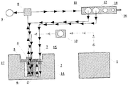
- a petrol / diesel oil tank 1 As shown, in the supply system there is a petrol / diesel oil tank 1 and a LPG tank 2.
- a sealed glass 3 is placed in the LPG tank 2, which by its upper plate 4 is fixed in the upper plate 5 of the cup 6, placed in the LPG tank 2,
- a solenoid valve 7 which controls the switching of fuel from petrol/diesel oil to LPG.
- petrol / diesel oil To one input of the solenoid valve 7 there is supplied petrol / diesel oil through solenoid valve 13, and to the second input LPG is supplied - the electrovalve 7 opens the LPG flow instead of gasoline / diesel oil and vice versa.
- From the sealed glass 3 fuel: petrol / diesel or LPG is fed to the high pressure pump 8 and then to the engine 9.
- the low pressure branch at the outlet of the high pressure pump 8 is connected to the manifold 10 of the small and big fuel circuit.
- the small circuit valve 11 is connected to the sealed glass 3, whereas the large circuit valve 12 is connected to the LPG tank 2.
- the operation of the system is as follows: when starting the supply system petrol / diesel is supplied to the inlet of the sealed glass 3, then the electrovalve 7 opens the petrol / diesel oil flow from the tank 1. From the sealed glass 3 petrol / diesel oil glass is supplied to the high pressure pump 8 and then to engine 9. In the manifold 10, the small circuit valve 11 is opened, petrol / diesel oil from the low pressure branch returns to the inside of the sealed glass 3 without mixing with LPG.
- the electrovalve 7 opens the LPG flow from the tank 2, petrol / diesel oil residues being in the small circuit flow into the sealed glass 3 and burn out in engine 9, in manifold 10 the small circuit valve 11 closes and the large circuit valve 12 opens and then LPG is fed to the supply system via the electrovalve 7.
- the big circuit valve 12 closes and the small circuit valve 11 opens, the electrovalve 7 closes the LPG supply and then petrol flows in a small circuit until the LPG is burned out in the system.
- a non-return valve 14 is mounted in the LPG return pipe, which blocks the gas flow from the LPG tank 2, and a manual shut-off valve 15 is installed on the LPG supply line to the low pressure pump.
- a manual service valve 16 is installed in the manifold 10 of the big and small circuit.
Landscapes
- Engineering & Computer Science (AREA)
- Chemical & Material Sciences (AREA)
- Oil, Petroleum & Natural Gas (AREA)
- Combustion & Propulsion (AREA)
- Mechanical Engineering (AREA)
- General Engineering & Computer Science (AREA)
- Output Control And Ontrol Of Special Type Engine (AREA)
Abstract
Description
- The subject of the invention is a system of supplying combustion engines with fuel, alternately with petrol / diesel oil or LPG, especially engines with multi-point or direct injection.
- The description of the Polish invention No.
PL222798 - According to the invention system supplying combustion engines with fuel, alternately with petrol / diesel oil or LPG, is characterized in that in the LPG tank in a sealed glass isolated from the LPG tank a low pressure pump is placed, which at the input is equipped with elecrovalve as a fuel change switch from petrol / diesel oil to LPG, wherein the low pressure branch at the outlet of the high pressure pump feeding the engine is connected to the manifold of the small and big fuel circuit, in which the small circuit valve is connected to the inlet of the low pressure pump in a sealed glass and the big circuit valve is connected to the LPG tank, where the petrol / diesel oil is supplied to the inlet of the sealed glass via the electrovalve.
- Sealed glass is placed in the LPG tank via the cup, the sealed glass being the upper plate attached to the main plate of the cup.
- On the main plate of the cup on the LPG return line a non-return valve is mounted to block gas outflow from the LPG tank and on the LPG supply line to the low pressure pump a manual shut-off valve is installed.
- In the manifold of the small and big circuit a manual service valve is mounted.
- The system according to the invention makes it possible to quickly change the fuel supplying the engine, while protecting against mixing of fuels in the LPG tank, which will be explained in detail when describing an example of the system solution.
- The system supplying the engines with fuel, alternately with petrol /diesel oil LPG, is shown in the drawing presenting its scheme.
- As shown, in the supply system there is a petrol / diesel oil tank 1 and a
LPG tank 2. A sealed glass 3 is placed in theLPG tank 2, which by its upper plate 4 is fixed in the upper plate 5 of the cup 6, placed in theLPG tank 2, At the inlet to the sealed glass 3 there is a solenoid valve 7, which controls the switching of fuel from petrol/diesel oil to LPG. To one input of the solenoid valve 7 there is supplied petrol / diesel oil throughsolenoid valve 13, and to the second input LPG is supplied - the electrovalve 7 opens the LPG flow instead of gasoline / diesel oil and vice versa. From the sealed glass 3 fuel: petrol / diesel or LPG is fed to the high pressure pump 8 and then to the engine 9. The low pressure branch at the outlet of the high pressure pump 8 is connected to themanifold 10 of the small and big fuel circuit. Thesmall circuit valve 11 is connected to the sealed glass 3, whereas thelarge circuit valve 12 is connected to theLPG tank 2. - The operation of the system is as follows: when starting the supply system petrol / diesel is supplied to the inlet of the sealed glass 3, then the electrovalve 7 opens the petrol / diesel oil flow from the tank 1. From the sealed glass 3 petrol / diesel oil glass is supplied to the high pressure pump 8 and then to engine 9. In the
manifold 10, thesmall circuit valve 11 is opened, petrol / diesel oil from the low pressure branch returns to the inside of the sealed glass 3 without mixing with LPG. When switching the system to LPG supply, the electrovalve 7 opens the LPG flow from thetank 2, petrol / diesel oil residues being in the small circuit flow into the sealed glass 3 and burn out in engine 9, inmanifold 10 thesmall circuit valve 11 closes and thelarge circuit valve 12 opens and then LPG is fed to the supply system via the electrovalve 7. Returning to the petrol / diesel oil supply in themanifold 10 thebig circuit valve 12 closes and thesmall circuit valve 11 opens, the electrovalve 7 closes the LPG supply and then petrol flows in a small circuit until the LPG is burned out in the system. - As you can see, the risk of mixing fuels in the
LPG tank 2 is minimized and more precisely the dilution of LPG inLPG tank 2 by petrol or diesel oil. - In order to facilitate service work in the main plate 5 of cup 6, a
non-return valve 14 is mounted in the LPG return pipe, which blocks the gas flow from theLPG tank 2, and a manual shut-offvalve 15 is installed on the LPG supply line to the low pressure pump. In themanifold 10 of the big and small circuit amanual service valve 16 is installed.
Claims (4)
- The system supplying combustion engines with fuel, alternately with petrol / diesel oil or LPG, with a high pressure pump supplying fuel to the engine, a low pressure pump supplying selected fuel to the high pressure pump, with a fuel type switch placed ahead of the low pressure pump, with valves controlling the operation of the fuel change system from petrol /diesel oil to LPG, characterized in that in the LPG tank (2) in a sealed glass (3) isolated from the LPG tank (2) a low pressure pump (17) is placed, which at the input is equipped with elecrovalve (7) as a fuel change switch from petrol / diesel oil to LPG, wherein the low pressure branch at the outlet of the high pressure pump (8) feeding the engine (9) is connected to the manifold (10) of the small and big fuel circuit, in which the small circuit valve (11) is connected to the inlet of the low pressure pump (17) in a sealed glass (3) and the big circuit valve (12) is connected to the LPG tank (2), where the petrol / diesel oil is supplied to the inlet of the sealed glass (3) via the electrovalve (7).
- A system according to claim 1, characterized in that the sealed glass (3) is placed in the LPG tank (2) via the cup (6), the sealed glass (3) being the upper plate (4) attached to the main plate (5) of the cup (6).
- A system according to claim 1, characterized in that on the main plate (5) of the cup (6) on the LPG return line a non-return valve (14) is mounted to block gas outflow from the LPG tank and on the LPG supply line to the low pressure pump (17) a manual shut-off valve is installed (15).
- A system according to claim 1, characterized in that in the manifold (10) of the small and big circuit a manual service valve (16) is mounted.
Applications Claiming Priority (1)
| Application Number | Priority Date | Filing Date | Title |
|---|---|---|---|
| PL425822A PL425822A1 (en) | 2018-06-05 | 2018-06-05 | A system supplying internal combustion engines with fuel, alternating with petrol / diesel oil or LPG gas |
Publications (3)
| Publication Number | Publication Date |
|---|---|
| EP3578784A1 true EP3578784A1 (en) | 2019-12-11 |
| EP3578784C0 EP3578784C0 (en) | 2024-11-13 |
| EP3578784B1 EP3578784B1 (en) | 2024-11-13 |
Family
ID=67211656
Family Applications (1)
| Application Number | Title | Priority Date | Filing Date |
|---|---|---|---|
| EP19460028.4A Active EP3578784B1 (en) | 2018-06-05 | 2019-05-31 | Petrol/diesel and lpg fuel supply system for internal combustion engines |
Country Status (2)
| Country | Link |
|---|---|
| EP (1) | EP3578784B1 (en) |
| PL (1) | PL425822A1 (en) |
Cited By (1)
| Publication number | Priority date | Publication date | Assignee | Title |
|---|---|---|---|---|
| WO2023003522A1 (en) * | 2021-07-23 | 2023-01-26 | Sparklpg D.O.O. | A dual liquid fuel injection system for an internal combustion direct injection engine, a fuel injection process with said system and an engine comprising said system |
Citations (5)
| Publication number | Priority date | Publication date | Assignee | Title |
|---|---|---|---|---|
| PL222798A1 (en) | 1980-03-12 | 1981-09-18 | Os Bad Rozwojowy Obrobki Scier | |
| DE20209413U1 (en) * | 2002-06-17 | 2002-09-26 | Winkelmann, Karlheinrich, Dipl.-Ing. (TH), 33617 Bielefeld | LPG tank |
| DE102007051677A1 (en) * | 2007-10-26 | 2009-04-30 | Karlheinrich Winkelmann | Fuel e.g. petrol, mixture controlled production and conveying method for e.g. Otto-engine, involves supplying fuel mixture in fuel mixture tank into high pressure fuel device, pressure rail, fuel injection valve, fuel loop and control unit |
| WO2015130182A1 (en) * | 2014-02-28 | 2015-09-03 | Certools Spółka Jawna Piotr Krzysztof Hanke | Fuel supply system for internal combustion engines |
| WO2018047021A1 (en) * | 2016-09-08 | 2018-03-15 | Lpgtech Sp. Z O. O. | Dual fuel direct injection system for feeding internal combustion engines |
-
2018
- 2018-06-05 PL PL425822A patent/PL425822A1/en unknown
-
2019
- 2019-05-31 EP EP19460028.4A patent/EP3578784B1/en active Active
Patent Citations (6)
| Publication number | Priority date | Publication date | Assignee | Title |
|---|---|---|---|---|
| PL222798A1 (en) | 1980-03-12 | 1981-09-18 | Os Bad Rozwojowy Obrobki Scier | |
| DE20209413U1 (en) * | 2002-06-17 | 2002-09-26 | Winkelmann, Karlheinrich, Dipl.-Ing. (TH), 33617 Bielefeld | LPG tank |
| DE102007051677A1 (en) * | 2007-10-26 | 2009-04-30 | Karlheinrich Winkelmann | Fuel e.g. petrol, mixture controlled production and conveying method for e.g. Otto-engine, involves supplying fuel mixture in fuel mixture tank into high pressure fuel device, pressure rail, fuel injection valve, fuel loop and control unit |
| WO2015130182A1 (en) * | 2014-02-28 | 2015-09-03 | Certools Spółka Jawna Piotr Krzysztof Hanke | Fuel supply system for internal combustion engines |
| PL222798B1 (en) * | 2014-02-28 | 2016-09-30 | Certools Spółka Jawna Piotr Czekalski Krzysztof Hanke | System feeding combustion engines with fuel |
| WO2018047021A1 (en) * | 2016-09-08 | 2018-03-15 | Lpgtech Sp. Z O. O. | Dual fuel direct injection system for feeding internal combustion engines |
Cited By (1)
| Publication number | Priority date | Publication date | Assignee | Title |
|---|---|---|---|---|
| WO2023003522A1 (en) * | 2021-07-23 | 2023-01-26 | Sparklpg D.O.O. | A dual liquid fuel injection system for an internal combustion direct injection engine, a fuel injection process with said system and an engine comprising said system |
Also Published As
| Publication number | Publication date |
|---|---|
| EP3578784C0 (en) | 2024-11-13 |
| EP3578784B1 (en) | 2024-11-13 |
| PL425822A1 (en) | 2019-12-16 |
Similar Documents
| Publication | Publication Date | Title |
|---|---|---|
| AU2008253607B2 (en) | A method of manufacturing and installation of high pressure liquid LPG fuel supply and dual or mixed fuel supply systems | |
| US9175650B2 (en) | High-pressure fuel pump for an internal combustion engine with direct injection | |
| AU2007200381A1 (en) | Method and apparatus for delivering two fuels to a direct injection internal combustion engine | |
| CN105275671A (en) | Method of supplying fuel to engine | |
| EP3036427B1 (en) | Fuel injection system and method for operating a multi-fuel piston engine | |
| US10989122B2 (en) | Dual-fuel fuel injection system for an internal combustion engine | |
| CN105829697A (en) | Dual-fuel injector | |
| US20140238353A1 (en) | Apparatus and Method for Detecting Leakage of Liquid Fuel into Gas Fuel Rail | |
| EP3578784B1 (en) | Petrol/diesel and lpg fuel supply system for internal combustion engines | |
| KR102316646B1 (en) | A system for adapting an internal combustion engine to be driven by gaseous gaseous fuel and liquid gaseous fuel | |
| KR102202003B1 (en) | Fuel supply system for internal combustion engines | |
| CN105190012A (en) | Mixed fuel supply system for internal combustion engine, vehicle, and mixed fuel supply method for internal combustion engine | |
| KR20140080426A (en) | Fuel supply system and method for operating the same | |
| KR101004331B1 (en) | Fuel supply device for liquefied gas internal combustion engine | |
| EA202091882A1 (en) | FUEL SUPPLY SYSTEM AND UNIT FOR INJECTING LIQUID STEAM UNDER HIGH PRESSURE INTO THE COMBUSTION CHAMBER | |
| KR102128643B1 (en) | Fuel injection circuit and method for operating a multi-fuel piston engine | |
| EP2014902A2 (en) | Method and device for cleaning reciprocating engines | |
| US7992547B2 (en) | Multiple gas fuel delivery system | |
| KR102034334B1 (en) | Fuel injection arrangement | |
| KR20180000225U (en) | Fuel Supply System of Engine | |
| RU198600U1 (en) | Liquid Methane Direct Injection System | |
| HRP20191062T1 (en) | System for adapting an internal combustion engine to be powered by gaseous fuel in gas phase and by gaseous fuel in liquid phase | |
| SU1413259A1 (en) | Injection system for alcohol and igniting diesel fuel | |
| RU2022119274A (en) | Automotive diesel fuel supply system with oxygenate fuels | |
| PH12022550904A1 (en) | Gas ultrasonic transducer system and method for operating a diesel common-rail engine |
Legal Events
| Date | Code | Title | Description |
|---|---|---|---|
| PUAI | Public reference made under article 153(3) epc to a published international application that has entered the european phase |
Free format text: ORIGINAL CODE: 0009012 |
|
| STAA | Information on the status of an ep patent application or granted ep patent |
Free format text: STATUS: THE APPLICATION HAS BEEN PUBLISHED |
|
| AK | Designated contracting states |
Kind code of ref document: A1 Designated state(s): AL AT BE BG CH CY CZ DE DK EE ES FI FR GB GR HR HU IE IS IT LI LT LU LV MC MK MT NL NO PL PT RO RS SE SI SK SM TR |
|
| AX | Request for extension of the european patent |
Extension state: BA ME |
|
| STAA | Information on the status of an ep patent application or granted ep patent |
Free format text: STATUS: REQUEST FOR EXAMINATION WAS MADE |
|
| 17P | Request for examination filed |
Effective date: 20200505 |
|
| RBV | Designated contracting states (corrected) |
Designated state(s): AL AT BE BG CH CY CZ DE DK EE ES FI FR GB GR HR HU IE IS IT LI LT LU LV MC MK MT NL NO PL PT RO RS SE SI SK SM TR |
|
| STAA | Information on the status of an ep patent application or granted ep patent |
Free format text: STATUS: EXAMINATION IS IN PROGRESS |
|
| 17Q | First examination report despatched |
Effective date: 20201012 |
|
| GRAP | Despatch of communication of intention to grant a patent |
Free format text: ORIGINAL CODE: EPIDOSNIGR1 |
|
| STAA | Information on the status of an ep patent application or granted ep patent |
Free format text: STATUS: GRANT OF PATENT IS INTENDED |
|
| INTG | Intention to grant announced |
Effective date: 20240307 |
|
| GRAS | Grant fee paid |
Free format text: ORIGINAL CODE: EPIDOSNIGR3 |
|
| GRAA | (expected) grant |
Free format text: ORIGINAL CODE: 0009210 |
|
| STAA | Information on the status of an ep patent application or granted ep patent |
Free format text: STATUS: THE PATENT HAS BEEN GRANTED |
|
| AK | Designated contracting states |
Kind code of ref document: B1 Designated state(s): AL AT BE BG CH CY CZ DE DK EE ES FI FR GB GR HR HU IE IS IT LI LT LU LV MC MK MT NL NO PL PT RO RS SE SI SK SM TR |
|
| REG | Reference to a national code |
Ref country code: GB Ref legal event code: FG4D |
|
| REG | Reference to a national code |
Ref country code: CH Ref legal event code: EP |
|
| REG | Reference to a national code |
Ref country code: IE Ref legal event code: FG4D |
|
| REG | Reference to a national code |
Ref country code: DE Ref legal event code: R096 Ref document number: 602019061864 Country of ref document: DE |
|
| U01 | Request for unitary effect filed |
Effective date: 20241203 |
|
| U07 | Unitary effect registered |
Designated state(s): AT BE BG DE DK EE FI FR IT LT LU LV MT NL PT RO SE SI Effective date: 20241211 |
|
| PG25 | Lapsed in a contracting state [announced via postgrant information from national office to epo] |
Ref country code: IS Free format text: LAPSE BECAUSE OF FAILURE TO SUBMIT A TRANSLATION OF THE DESCRIPTION OR TO PAY THE FEE WITHIN THE PRESCRIBED TIME-LIMIT Effective date: 20250313 Ref country code: HR Free format text: LAPSE BECAUSE OF FAILURE TO SUBMIT A TRANSLATION OF THE DESCRIPTION OR TO PAY THE FEE WITHIN THE PRESCRIBED TIME-LIMIT Effective date: 20241113 |
|
| PG25 | Lapsed in a contracting state [announced via postgrant information from national office to epo] |
Ref country code: ES Free format text: LAPSE BECAUSE OF FAILURE TO SUBMIT A TRANSLATION OF THE DESCRIPTION OR TO PAY THE FEE WITHIN THE PRESCRIBED TIME-LIMIT Effective date: 20241113 |
|
| PG25 | Lapsed in a contracting state [announced via postgrant information from national office to epo] |
Ref country code: NO Free format text: LAPSE BECAUSE OF FAILURE TO SUBMIT A TRANSLATION OF THE DESCRIPTION OR TO PAY THE FEE WITHIN THE PRESCRIBED TIME-LIMIT Effective date: 20250213 |
|
| PG25 | Lapsed in a contracting state [announced via postgrant information from national office to epo] |
Ref country code: GR Free format text: LAPSE BECAUSE OF FAILURE TO SUBMIT A TRANSLATION OF THE DESCRIPTION OR TO PAY THE FEE WITHIN THE PRESCRIBED TIME-LIMIT Effective date: 20250214 |
|
| PG25 | Lapsed in a contracting state [announced via postgrant information from national office to epo] |
Ref country code: PL Free format text: LAPSE BECAUSE OF FAILURE TO SUBMIT A TRANSLATION OF THE DESCRIPTION OR TO PAY THE FEE WITHIN THE PRESCRIBED TIME-LIMIT Effective date: 20241113 |
|
| PG25 | Lapsed in a contracting state [announced via postgrant information from national office to epo] |
Ref country code: RS Free format text: LAPSE BECAUSE OF FAILURE TO SUBMIT A TRANSLATION OF THE DESCRIPTION OR TO PAY THE FEE WITHIN THE PRESCRIBED TIME-LIMIT Effective date: 20250213 |
|
| U20 | Renewal fee for the european patent with unitary effect paid |
Year of fee payment: 7 Effective date: 20250502 |
|
| PG25 | Lapsed in a contracting state [announced via postgrant information from national office to epo] |
Ref country code: SM Free format text: LAPSE BECAUSE OF FAILURE TO SUBMIT A TRANSLATION OF THE DESCRIPTION OR TO PAY THE FEE WITHIN THE PRESCRIBED TIME-LIMIT Effective date: 20241113 |
|
| PG25 | Lapsed in a contracting state [announced via postgrant information from national office to epo] |
Ref country code: SK Free format text: LAPSE BECAUSE OF FAILURE TO SUBMIT A TRANSLATION OF THE DESCRIPTION OR TO PAY THE FEE WITHIN THE PRESCRIBED TIME-LIMIT Effective date: 20241113 |
|
| PG25 | Lapsed in a contracting state [announced via postgrant information from national office to epo] |
Ref country code: CZ Free format text: LAPSE BECAUSE OF FAILURE TO SUBMIT A TRANSLATION OF THE DESCRIPTION OR TO PAY THE FEE WITHIN THE PRESCRIBED TIME-LIMIT Effective date: 20241113 |
|
| PLBE | No opposition filed within time limit |
Free format text: ORIGINAL CODE: 0009261 |
|
| STAA | Information on the status of an ep patent application or granted ep patent |
Free format text: STATUS: NO OPPOSITION FILED WITHIN TIME LIMIT |
|
| 26N | No opposition filed |
Effective date: 20250814 |
|
| REG | Reference to a national code |
Ref country code: CH Ref legal event code: H13 Free format text: ST27 STATUS EVENT CODE: U-0-0-H10-H13 (AS PROVIDED BY THE NATIONAL OFFICE) Effective date: 20251223 |
|
| PG25 | Lapsed in a contracting state [announced via postgrant information from national office to epo] |
Ref country code: CH Free format text: LAPSE BECAUSE OF NON-PAYMENT OF DUE FEES Effective date: 20250531 |
|
| GBPC | Gb: european patent ceased through non-payment of renewal fee |
Effective date: 20250531 |
|
| PG25 | Lapsed in a contracting state [announced via postgrant information from national office to epo] |
Ref country code: MC Free format text: LAPSE BECAUSE OF FAILURE TO SUBMIT A TRANSLATION OF THE DESCRIPTION OR TO PAY THE FEE WITHIN THE PRESCRIBED TIME-LIMIT Effective date: 20241113 |
|
| PG25 | Lapsed in a contracting state [announced via postgrant information from national office to epo] |
Ref country code: GB Free format text: LAPSE BECAUSE OF NON-PAYMENT OF DUE FEES Effective date: 20250531 |
|
| PG25 | Lapsed in a contracting state [announced via postgrant information from national office to epo] |
Ref country code: IE Free format text: LAPSE BECAUSE OF NON-PAYMENT OF DUE FEES Effective date: 20250531 |