EP3578780A1 - Dual direction windmill pump for geared turbofan engines - Google Patents
Dual direction windmill pump for geared turbofan engines Download PDFInfo
- Publication number
- EP3578780A1 EP3578780A1 EP19178502.1A EP19178502A EP3578780A1 EP 3578780 A1 EP3578780 A1 EP 3578780A1 EP 19178502 A EP19178502 A EP 19178502A EP 3578780 A1 EP3578780 A1 EP 3578780A1
- Authority
- EP
- European Patent Office
- Prior art keywords
- gear
- shaft
- reverse
- rotating
- coupled
- Prior art date
- Legal status (The legal status is an assumption and is not a legal conclusion. Google has not performed a legal analysis and makes no representation as to the accuracy of the status listed.)
- Granted
Links
Images


Classifications
-
- F—MECHANICAL ENGINEERING; LIGHTING; HEATING; WEAPONS; BLASTING
- F01—MACHINES OR ENGINES IN GENERAL; ENGINE PLANTS IN GENERAL; STEAM ENGINES
- F01D—NON-POSITIVE DISPLACEMENT MACHINES OR ENGINES, e.g. STEAM TURBINES
- F01D25/00—Component parts, details, or accessories, not provided for in, or of interest apart from, other groups
- F01D25/18—Lubricating arrangements
- F01D25/20—Lubricating arrangements using lubrication pumps
-
- F—MECHANICAL ENGINEERING; LIGHTING; HEATING; WEAPONS; BLASTING
- F01—MACHINES OR ENGINES IN GENERAL; ENGINE PLANTS IN GENERAL; STEAM ENGINES
- F01D—NON-POSITIVE DISPLACEMENT MACHINES OR ENGINES, e.g. STEAM TURBINES
- F01D15/00—Adaptations of machines or engines for special use; Combinations of engines with devices driven thereby
- F01D15/08—Adaptations for driving, or combinations with, pumps
-
- F—MECHANICAL ENGINEERING; LIGHTING; HEATING; WEAPONS; BLASTING
- F01—MACHINES OR ENGINES IN GENERAL; ENGINE PLANTS IN GENERAL; STEAM ENGINES
- F01D—NON-POSITIVE DISPLACEMENT MACHINES OR ENGINES, e.g. STEAM TURBINES
- F01D15/00—Adaptations of machines or engines for special use; Combinations of engines with devices driven thereby
- F01D15/12—Combinations with mechanical gearing
-
- F—MECHANICAL ENGINEERING; LIGHTING; HEATING; WEAPONS; BLASTING
- F02—COMBUSTION ENGINES; HOT-GAS OR COMBUSTION-PRODUCT ENGINE PLANTS
- F02C—GAS-TURBINE PLANTS; AIR INTAKES FOR JET-PROPULSION PLANTS; CONTROLLING FUEL SUPPLY IN AIR-BREATHING JET-PROPULSION PLANTS
- F02C7/00—Features, components parts, details or accessories, not provided for in, or of interest apart form groups F02C1/00 - F02C6/00; Air intakes for jet-propulsion plants
- F02C7/06—Arrangements of bearings; Lubricating
-
- F—MECHANICAL ENGINEERING; LIGHTING; HEATING; WEAPONS; BLASTING
- F02—COMBUSTION ENGINES; HOT-GAS OR COMBUSTION-PRODUCT ENGINE PLANTS
- F02C—GAS-TURBINE PLANTS; AIR INTAKES FOR JET-PROPULSION PLANTS; CONTROLLING FUEL SUPPLY IN AIR-BREATHING JET-PROPULSION PLANTS
- F02C7/00—Features, components parts, details or accessories, not provided for in, or of interest apart form groups F02C1/00 - F02C6/00; Air intakes for jet-propulsion plants
- F02C7/32—Arrangement, mounting, or driving, of auxiliaries
-
- F—MECHANICAL ENGINEERING; LIGHTING; HEATING; WEAPONS; BLASTING
- F02—COMBUSTION ENGINES; HOT-GAS OR COMBUSTION-PRODUCT ENGINE PLANTS
- F02C—GAS-TURBINE PLANTS; AIR INTAKES FOR JET-PROPULSION PLANTS; CONTROLLING FUEL SUPPLY IN AIR-BREATHING JET-PROPULSION PLANTS
- F02C7/00—Features, components parts, details or accessories, not provided for in, or of interest apart form groups F02C1/00 - F02C6/00; Air intakes for jet-propulsion plants
- F02C7/36—Power transmission arrangements between the different shafts of the gas turbine plant, or between the gas-turbine plant and the power user
-
- F—MECHANICAL ENGINEERING; LIGHTING; HEATING; WEAPONS; BLASTING
- F05—INDEXING SCHEMES RELATING TO ENGINES OR PUMPS IN VARIOUS SUBCLASSES OF CLASSES F01-F04
- F05D—INDEXING SCHEME FOR ASPECTS RELATING TO NON-POSITIVE-DISPLACEMENT MACHINES OR ENGINES, GAS-TURBINES OR JET-PROPULSION PLANTS
- F05D2220/00—Application
- F05D2220/30—Application in turbines
- F05D2220/34—Application in turbines in ram-air turbines ("RATS")
-
- F—MECHANICAL ENGINEERING; LIGHTING; HEATING; WEAPONS; BLASTING
- F05—INDEXING SCHEMES RELATING TO ENGINES OR PUMPS IN VARIOUS SUBCLASSES OF CLASSES F01-F04
- F05D—INDEXING SCHEME FOR ASPECTS RELATING TO NON-POSITIVE-DISPLACEMENT MACHINES OR ENGINES, GAS-TURBINES OR JET-PROPULSION PLANTS
- F05D2260/00—Function
- F05D2260/40—Transmission of power
- F05D2260/403—Transmission of power through the shape of the drive components
- F05D2260/4031—Transmission of power through the shape of the drive components as in toothed gearing
-
- F—MECHANICAL ENGINEERING; LIGHTING; HEATING; WEAPONS; BLASTING
- F05—INDEXING SCHEMES RELATING TO ENGINES OR PUMPS IN VARIOUS SUBCLASSES OF CLASSES F01-F04
- F05D—INDEXING SCHEME FOR ASPECTS RELATING TO NON-POSITIVE-DISPLACEMENT MACHINES OR ENGINES, GAS-TURBINES OR JET-PROPULSION PLANTS
- F05D2260/00—Function
- F05D2260/40—Transmission of power
- F05D2260/403—Transmission of power through the shape of the drive components
- F05D2260/4031—Transmission of power through the shape of the drive components as in toothed gearing
- F05D2260/40311—Transmission of power through the shape of the drive components as in toothed gearing of the epicyclical, planetary or differential type
-
- F—MECHANICAL ENGINEERING; LIGHTING; HEATING; WEAPONS; BLASTING
- F05—INDEXING SCHEMES RELATING TO ENGINES OR PUMPS IN VARIOUS SUBCLASSES OF CLASSES F01-F04
- F05D—INDEXING SCHEME FOR ASPECTS RELATING TO NON-POSITIVE-DISPLACEMENT MACHINES OR ENGINES, GAS-TURBINES OR JET-PROPULSION PLANTS
- F05D2260/00—Function
- F05D2260/98—Lubrication
-
- F—MECHANICAL ENGINEERING; LIGHTING; HEATING; WEAPONS; BLASTING
- F16—ENGINEERING ELEMENTS AND UNITS; GENERAL MEASURES FOR PRODUCING AND MAINTAINING EFFECTIVE FUNCTIONING OF MACHINES OR INSTALLATIONS; THERMAL INSULATION IN GENERAL
- F16H—GEARING
- F16H61/00—Control functions within control units of change-speed- or reversing-gearings for conveying rotary motion ; Control of exclusively fluid gearing, friction gearing, gearings with endless flexible members or other particular types of gearing
- F16H61/0021—Generation or control of line pressure
- F16H2061/0037—Generation or control of line pressure characterised by controlled fluid supply to lubrication circuits of the gearing
-
- Y—GENERAL TAGGING OF NEW TECHNOLOGICAL DEVELOPMENTS; GENERAL TAGGING OF CROSS-SECTIONAL TECHNOLOGIES SPANNING OVER SEVERAL SECTIONS OF THE IPC; TECHNICAL SUBJECTS COVERED BY FORMER USPC CROSS-REFERENCE ART COLLECTIONS [XRACs] AND DIGESTS
- Y02—TECHNOLOGIES OR APPLICATIONS FOR MITIGATION OR ADAPTATION AGAINST CLIMATE CHANGE
- Y02T—CLIMATE CHANGE MITIGATION TECHNOLOGIES RELATED TO TRANSPORTATION
- Y02T50/00—Aeronautics or air transport
- Y02T50/60—Efficient propulsion technologies, e.g. for aircraft
Definitions
- the disclosure relates generally to lubrication systems for journal bearings and geared architectures.
- Gas turbine engines may comprise a turbine section and a fan section.
- a fan section may be driven by a geared architecture such as, for example, epicyclical gear assemblies and the like.
- An epicyclical gear assembly may be a speed reduction device and thereby tend to allow a fan of the fan section to be driven at a different speed than a turbine of the turbine section.
- a shaft driven by the turbine provides an input to the epicyclical gear assembly which, in turn drives the fan at a reduced speed such that both the turbine and the fan tend to rotate at closer to a more optimal speed.
- a lubrication comprising a shaft including a shaft gear, a pump configured to supply a flow of lubricant to a component benefiting from lubrication and an input gear train coupled to the shaft gear and configured to drive the pump with a unidirectional rotation in response to a forward rotation and an reverse rotation of the shaft gear.
- the input gear train may comprise a primary gear coupled to a common shaft. In various embodiments, the input gear train may further comprise a forward shaft and a forward gear about the common shaft, wherein the forward gear is coupled to the forward shaft. In various embodiments, the input gear train further comprises a reverse shaft and a reverse gear about the common shaft, wherein the reverse gear is coupled to the reverse shaft. In various embodiments, the input gear train further comprises a forward clutch coupled to the forward shaft and a reverse clutch coupled to the reverse shaft.
- the forward clutch and the reverse clutch are selectively coupled to the common shaft, wherein the forward clutch is configured to lock in response to rotating the common shaft in a first direction, wherein the reverse clutch is configured to lock in response to rotating the common shaft in a second direction.
- the input gear train further comprises an idler gear supported by an idler shaft and coupled to the reverse gear.
- the input gear train further comprises a pump gear coupled to the forward gear and the idler gear, the pump gear supported by a pump shaft coupled to the pump.
- the present disclosure provides a gas turbine engine comprising a compressor section configured to compress a gas, a combustor section aft of the compressor section configured to combust the gas, a turbine section aft of the combustor section configured to extract work from the combusted gas, and a lubrication system comprising a shaft including a shaft gear, a pump configured to supply a flow of lubricant to a component benefiting from lubrication, and an input gear train coupled to the shaft gear and configured to drive the pump with a unidirectional rotation in response to a forward rotation and an reverse rotation of the shaft gear.
- the input gear train may comprise a primary gear coupled to a common shaft. In various embodiments, the input gear train may further comprise a forward shaft and a forward gear about the common shaft, wherein the forward gear is coupled to the forward shaft. In various embodiments, the input gear train further comprises a reverse shaft and a reverse gear about the common shaft, wherein the reverse gear is coupled to the reverse shaft. In various embodiments, the input gear train further comprises a forward clutch coupled to the forward shaft and a reverse clutch coupled to the reverse shaft.
- the forward clutch and the reverse clutch are selectively coupled to the common shaft, wherein the forward clutch is configured to lock in response to rotating the common shaft in a first direction, wherein the reverse clutch is configured to lock in response to rotating the common shaft in a second direction.
- the input gear train further comprises an idler gear supported by an idler shaft and coupled to the reverse gear.
- the input gear train further comprises a pump gear coupled to the forward gear and the idler gear, the pump gear supported by a pump shaft coupled to the pump.
- the shaft is in communication with a fan, wherein the shaft rotates in a reverse direction in response to a windmilling of the fan, wherein the component comprises a geared architecture including at least one journal bearing.
- the present disclosure provides a method of lubricating a geared architecture comprising rotating a shaft gear in a forward direction and rotating a primary gear and common shaft in a first direction, locking a forward clutch in response to the rotating in the first direction and rotating a forward gear in the first direction, and generating a flow of lubricant in response to rotating the forward gear in the first direction.
- the method may include rotating the shaft gear in a reverse direction and rotating the primary gear and the common shaft in a second direction, unlocking the forward clutch and locking a reverse clutch in response to the rotating in the second direction and rotating a reverse gear in the second direction, and generating the flow of lubricant in response to rotating the reverse gear in the second direction.
- the method may further include idling at least one of the forward gear or the reverse gear in response to rotating the common shaft.
- aft refers to the direction associated with the tail (e.g., the back end) of an aircraft, or generally, to the direction of exhaust of a gas turbine engine.
- forward refers to the direction associated with the intake (e.g., the front end) of a gas turbine engine.
- upstream is used to refer to directions and positions located closer to the source than directions and positions referenced as “downstream.”
- distal refers to the direction outward, or generally, away from a reference component.
- proximate refers to a direction inward, or generally, towards a reference component.
- a first component that is “radially outward” or “outboard” of a second component means that the first component is positioned at a greater distance away from a central longitudinal axis of the gas turbine engine.
- a first component that is “radially inward” or “inboard” of a second component means that the first component is positioned closer to the engine central longitudinal axis than the second component.
- the terminology “radially outward” and “radially inward” may also be used relative to references other than the engine central longitudinal axis.
- Gas turbine engine 20 may be a two-spool turbofan that generally incorporates a fan section 22, a compressor section 24, a combustor section 26 and a turbine section 28.
- fan section 22 can drive air along a bypass flow-path B while compressor section 24 can drive air for compression and communication into combustor section 26 then expansion through turbine section 28.
- turbofan gas turbine engine 20 Although depicted as a turbofan gas turbine engine 20 herein, it should be understood that the concepts described herein are not limited to use with turbofans as the teachings may be applied to other types of turbine engines including turbojet engines, a low-bypass turbofans, a high bypass turbofans, or any other gas turbine known to those skilled in the art including single spool and three-spool architectures.
- Gas turbine engine 20 may generally comprise a low speed spool 30 and a high speed spool 32 mounted for rotation about an engine central longitudinal axis A-A' relative to an engine static structure 36 via one or more bearing systems 38 (shown as bearing system 38-1 and bearing system 38-2 in FIG. 2 ). It should be understood that various bearing systems 38 at various locations may alternatively or additionally be provided, including for example, bearing system 38, bearing system 38-1, and bearing system 38-2.
- Low speed spool 30 may generally comprise an inner shaft 40 that interconnects a fan 42, a low pressure (or first) compressor section 44 (also referred to a low pressure compressor 44) and a low pressure (or first) turbine section 46.
- Inner shaft 40 may be connected to fan 42 through a geared architecture 48 that can drive fan 42 at a lower speed than low speed spool 30.
- Geared architecture 48 may comprise a gear assembly 60 enclosed within a gear housing 62.
- Gear assembly 60 couples inner shaft 40 to a rotating fan structure which may comprise a fan shaft 66.
- High speed spool 32 may comprise an outer shaft 50 that interconnects a high pressure compressor (“HPC") 52 (e.g., a second compressor section) and high pressure (or second) turbine section 54.
- HPC high pressure compressor
- a combustor 56 may be located between HPC 52 and high pressure turbine 54.
- a mid-turbine frame 57 of engine static structure 36 may be located generally between high pressure turbine 54 and low pressure turbine 46.
- Mid-turbine frame 57 may support one or more bearing systems 38 in turbine section 28.
- Inner shaft 40 and outer shaft 50 may be concentric and rotate via bearing systems 38 about the engine central longitudinal axis A-A', which is collinear with their longitudinal axes.
- a "high pressure" compressor or turbine experiences a higher pressure than a corresponding "low pressure” compressor or turbine.
- the core airflow C may be compressed by low pressure compressor 44 then HPC 52, mixed and burned with fuel in combustor 56, then expanded over high pressure turbine 54 and low pressure turbine 46.
- Mid-turbine frame 57 includes airfoils 59 which are in the core airflow path.
- Low pressure turbine 46, and high pressure turbine 54 rotationally drive the respective low speed spool 30 and high speed spool 32 in response to the expansion.
- HPC 52 and LPC 44 may comprise alternating rows of rotating rotors 64 and stationary stators 65.
- Stators may have a cantilevered configuration or a shrouded configuration.
- a stator may comprise a stator vane, a casing support and a hub support.
- a stator vane may be supported along an outer diameter by a casing support and along an inner diameter by a hub support.
- a cantilevered stator may comprise a stator vane that is only retained and/or supported at the casing (e.g., along an outer diameter).
- rotors may be configured to compress and spin a fluid flow.
- Stators may be configured to receive and straighten the fluid flow.
- the fluid flow discharged from the trailing edge of stators may be straightened (e.g., the flow may be directed in a substantially parallel path to the centerline of the engine and/or HPC) to increase and/or improve the efficiency of the engine and, more specifically, to achieve maximum and/or near maximum compression and efficiency when the straightened air is compressed and spun by rotor 64.
- fan section 22 may further comprise a lubrication system 200 driven by an input gear train 300.
- Input gear train 300 is driven by shaft gear 302 and includes primary gear train 206 and reverse gear train 208.
- shaft gear 302 is disposed about fan shaft 66 which is driven by geared architecture 48 during normal engine operating conditions.
- low pressure turbine 46 drives inner shaft 40 and, in turn, gear assembly 60 rotates fan shaft 66 and shaft gear 302 in a forward direction 304. Rotating fan shaft 66 in the forward direction 304 thereby drives fan 42 forward tending to produce thrust.
- Lubrication system 200 includes input gear train 300 and comprises a gear pump 202 which sends flow of a lubricant (e.g, via a conduit 204 or other suitable lubricant channel) to geared architecture 48 tending thereby to prolong the operational life of geared architecture 48.
- gear pump 202 In shaft gear 302 rotating in the forward direction 304, gear pump 202 is driven by primary gear train 206 (stippled components shown in FIG. 2A ).
- primary gear train 206 illustrated components shown in FIG. 2A .
- airflow over fan 42 may tend to rotate fan 42 (i.e. a phenomenon known as windmilling) and in response drive fan shaft 66 and thereby shaft gear 302 in a reverse direction 305.
- a pump such as gear pump 202, may comprise any suitable rotary pump such as, for example, a vane pump, a screw pump, a centrifugal pump, g-rotor pump, and/or the like.
- input gear train 300 includes the primary gear train 206 having a primary gear 210 which is coupled to common shaft 212.
- Common shaft 212 is supported by bearing assembly 217 and coupled to forward clutch 214 (i.e., a first clutch) and reverse clutch 216 (i.e., a second clutch).
- Forward clutch 214 is coupled to forward shaft 218 which is supported by bearing assembly 215 and lies radially outward of common shaft 212, in turn, common shaft 212 supports bearing assembly 215.
- Forward shaft 218 supports forward gear 220 which is disposed about common shaft 212 and is selectively coupled thereto by forward clutch 214 such that forward gear 220 will rotate with common shaft 212 only in one desired direction.
- Forward gear 220 is coupled to pump gear 222 which, in turn, is supported on pump shaft 224 which drives gear pump 202.
- rotation of the shaft gear 302 in the forward direction 304 results in rotation of the primary gear 210 and common shaft 212 in a first direction 306 which tends to engage forward clutch 214 (as illustrated by vertical stripes).
- Engaging forward clutch 214 locks forward shaft 218 to common shaft 212 thereby transmitting rotation of the common shaft 212 to the forward gear 220 and causing forward gear 220 to rotate in the first direction 306.
- Forward gear 220 transmits torque 238 from common shaft 212 to pump gear 222 thereby inducing drive rotation 308 (i.e., a unidirectional rotation) of pump gear 222 and pump shaft 224 tending thereby to supply lubricant from gear pump 202 to geared architecture 48.
- gear pump 202 may be configured to supply lubricant in response to a unidirectional rotation of pump shaft 224 and drive rotation 308 may therefore be a unidirectional rotation. Stated another way, gear pump 202 may not supply lubricant in response to a rotation of pump shaft 224 in a direction opposite drive rotation 308 and may tend to be damaged by such a rotation.
- geared architecture 48 includes a sun gear 240 which is circumscribed by a plurality of intermediate gears 242 supported by a carrier 244 and engaged with a surrounding ring gear 246.
- each of the intermediate gears 242 may be supported by a journal bearing 248 coupled to carrier 244.
- each of the journal bearings 248 tend to benefit from a constant flow of lubricant tending thereby to inhibit wear. It is therefore desirable to ensure a flow of lubricant during operation and during windmilling. It should be understood that, although a geared architecture for driving a fan is disclosed, lubrication system 200 may supply lubricant to any component benefiting from lubrication during windmilling or normal operation of a gas turbine engine.
- input gear train 300 includes the reverse gear train 208 having the primary gear 210, common shaft 212, forward clutch 214, and reverse clutch 216.
- Reverse gear train 208 includes a reverse shaft 226 radially outward of common shaft 212 coupled to reverse clutch 216 and supported by bearing assembly 217.
- Reverse shaft 226 is further supported by reverse shaft bearing assembly 228 about the reverse shaft.
- Reverse shaft 226 supports a reverse gear 230 which is disposed about common shaft 212 and selectively coupled thereto by reverse clutch 216 such that it will rotate with common shaft 212 only in one desired direction.
- Reverse gear 230 is coupled to idler gear 232 which is supported by idler shaft 234 and idler bearing 236.
- Idler gear 232 is coupled to pump gear 222.
- rotation of shaft gear 302 in the reverse direction 305 results in rotation of the primary gear 210 and common shaft 212 in a second direction 307 leaving forward clutch 214 unlocked and forward gear 220 idle.
- reverse clutch 216 is engaged (as illustrated by vertical stripes) locking reverse shaft 226 to common shaft 212 thereby transmitting rotation of the common shaft 212 to the reverse gear 230 and causing the reverse gear 230 to rotate in the second direction 307.
- idler gear In response to reverse gear 230 rotating in the second direction 307 idler gear is caused to rotate in the first direction 306 and transmit torque 238 from common shaft 212 to pump gear 222 thereby inducing drive rotation 308 of pump gear 222 and pump shaft 224 tending thereby to supply lubricant from gear pump 202 to geared architecture 48.
- gears of input gear train 300 may be engaged with each other and will turn in all instances where primary gear 210 is driving rotation of common shaft 212.
- forward gear 220 and reverse gear 230 are each selectively coupled to common shaft 212 by a corresponding clutch (forward clutch 214 and reverse clutch 216) at their corresponding shaft (forward shaft 218 and reverse shaft 226). Accordingly, only rotation of common shaft 212 in the desired direction will be transmitted to the respective gear and shaft set which otherwise will idle over the common shaft and not transmit torque from common shaft 212.
- torque may be supplied to induce drive rotation 308 for gear pump 202 irrespective of a rotational direction of common shaft 212.
- forward clutch 214 and reverse clutch 216 may be an overrunning clutch design using a sprag configuration which may comprise an inner race 402 and an outer race 404 separated by an annular space 406.
- annular space 406 Within annular space 406 are a plurality of sprags 408 each of which may be shaped such that the transmit power between the inner race 402 and the outer race 404 when rotating in one direction and allow independent rotation between the two races 402, 404 when rotated in an opposite direction.
- the sprag clutch design provides for the selective coupling between the inner race 402 and the outer race 404 which may be utilized to transmit torque in one desired direction. It should be appreciated that although a sprag clutch is disclosed other clutch configurations may be used and are within the contemplation of this disclosure.
- a method 500 of lubricating a geared architecture such as geared architecture 48 may comprise rotating a shaft gear in a forward direction and rotating a primary gear and common shaft in a first direction (step 502), locking a forward clutch in response to the rotating in the first direction and rotating a forward gear in the first direction (step 504), and generating a flow of lubricant in response to rotating the forward gear in the first direction (step 506).
- Method 500 may include rotating the shaft gear in a reverse direction and rotating the primary gear and the common shaft in a second direction, locking a reverse clutch in response to the rotating in the second direction and rotating a reverse gear in the second direction, and generating the flow of lubricant in response to rotating the reverse gear in the second direction (step 508).
- Method 500 may further include idling at least one of the forward gear or the reverse gear in response to rotating the common shaft (step 510).
- references to “one embodiment”, “an embodiment”, “an example embodiment”, etc. indicate that the embodiment described may include a particular feature, structure, or characteristic, but every embodiment may not necessarily include the particular feature, structure, or characteristic. Moreover, such phrases are not necessarily referring to the same embodiment. Further, when a particular feature, structure, or characteristic is described in connection with an embodiment, it is submitted that it is within the knowledge of one skilled in the art to affect such feature, structure, or characteristic in connection with other embodiments whether or not explicitly described. After reading the description, it will be apparent to one skilled in the relevant art(s) how to implement the disclosure in alternative embodiment
Landscapes
- Engineering & Computer Science (AREA)
- Mechanical Engineering (AREA)
- General Engineering & Computer Science (AREA)
- Chemical & Material Sciences (AREA)
- Combustion & Propulsion (AREA)
- General Details Of Gearings (AREA)
- Gear Transmission (AREA)
Abstract
Description
- The disclosure relates generally to lubrication systems for journal bearings and geared architectures.
- Gas turbine engines may comprise a turbine section and a fan section. A fan section may be driven by a geared architecture such as, for example, epicyclical gear assemblies and the like. An epicyclical gear assembly may be a speed reduction device and thereby tend to allow a fan of the fan section to be driven at a different speed than a turbine of the turbine section. In such architectures, a shaft driven by the turbine provides an input to the epicyclical gear assembly which, in turn drives the fan at a reduced speed such that both the turbine and the fan tend to rotate at closer to a more optimal speed.
- In various embodiments the present disclosure provides a lubrication comprising a shaft including a shaft gear, a pump configured to supply a flow of lubricant to a component benefiting from lubrication and an input gear train coupled to the shaft gear and configured to drive the pump with a unidirectional rotation in response to a forward rotation and an reverse rotation of the shaft gear.
- In various embodiments, the input gear train may comprise a primary gear coupled to a common shaft. In various embodiments, the input gear train may further comprise a forward shaft and a forward gear about the common shaft, wherein the forward gear is coupled to the forward shaft. In various embodiments, the input gear train further comprises a reverse shaft and a reverse gear about the common shaft, wherein the reverse gear is coupled to the reverse shaft. In various embodiments, the input gear train further comprises a forward clutch coupled to the forward shaft and a reverse clutch coupled to the reverse shaft. In various embodiments, the forward clutch and the reverse clutch are selectively coupled to the common shaft, wherein the forward clutch is configured to lock in response to rotating the common shaft in a first direction, wherein the reverse clutch is configured to lock in response to rotating the common shaft in a second direction. In various embodiments, the input gear train further comprises an idler gear supported by an idler shaft and coupled to the reverse gear. In various embodiments, the input gear train further comprises a pump gear coupled to the forward gear and the idler gear, the pump gear supported by a pump shaft coupled to the pump.
- In various embodiments, the present disclosure provides a gas turbine engine comprising a compressor section configured to compress a gas, a combustor section aft of the compressor section configured to combust the gas, a turbine section aft of the combustor section configured to extract work from the combusted gas, and a lubrication system comprising a shaft including a shaft gear, a pump configured to supply a flow of lubricant to a component benefiting from lubrication, and an input gear train coupled to the shaft gear and configured to drive the pump with a unidirectional rotation in response to a forward rotation and an reverse rotation of the shaft gear.
- In various embodiments, the input gear train may comprise a primary gear coupled to a common shaft. In various embodiments, the input gear train may further comprise a forward shaft and a forward gear about the common shaft, wherein the forward gear is coupled to the forward shaft. In various embodiments, the input gear train further comprises a reverse shaft and a reverse gear about the common shaft, wherein the reverse gear is coupled to the reverse shaft. In various embodiments, the input gear train further comprises a forward clutch coupled to the forward shaft and a reverse clutch coupled to the reverse shaft. In various embodiments, the forward clutch and the reverse clutch are selectively coupled to the common shaft, wherein the forward clutch is configured to lock in response to rotating the common shaft in a first direction, wherein the reverse clutch is configured to lock in response to rotating the common shaft in a second direction. In various embodiments, the input gear train further comprises an idler gear supported by an idler shaft and coupled to the reverse gear. In various embodiments, the input gear train further comprises a pump gear coupled to the forward gear and the idler gear, the pump gear supported by a pump shaft coupled to the pump. In various embodiments, the shaft is in communication with a fan, wherein the shaft rotates in a reverse direction in response to a windmilling of the fan, wherein the component comprises a geared architecture including at least one journal bearing.
- In various embodiments, the present disclosure provides a method of lubricating a geared architecture comprising rotating a shaft gear in a forward direction and rotating a primary gear and common shaft in a first direction, locking a forward clutch in response to the rotating in the first direction and rotating a forward gear in the first direction, and generating a flow of lubricant in response to rotating the forward gear in the first direction. The method may include rotating the shaft gear in a reverse direction and rotating the primary gear and the common shaft in a second direction, unlocking the forward clutch and locking a reverse clutch in response to the rotating in the second direction and rotating a reverse gear in the second direction, and generating the flow of lubricant in response to rotating the reverse gear in the second direction. The method may further include idling at least one of the forward gear or the reverse gear in response to rotating the common shaft.
- The forgoing features and elements may be combined in various combinations without exclusivity, unless expressly indicated herein otherwise. These features and elements as well as the operation of the disclosed embodiments will become more apparent in light of the following description and accompanying drawings.
- The subject matter of the present disclosure is particularly pointed out and distinctly claimed in the concluding portion of the specification. A more complete understanding of the present disclosures, however, may best be obtained by referring to the detailed description and claims when considered in connection with the drawing figures, wherein like numerals denote like elements. Accordingly, elements with like element numbering may be shown in the figures, but may not be necessarily be repeated herein for the sake of clarity.
-
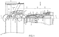
FIG. 1 illustrates a schematic cross-section of an exemplary gas turbine engine, in accordance with various embodiments; -
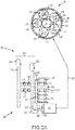
FIG. 2A illustrates a schematic view of a lubrication system, in accordance with various embodiments; -
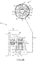
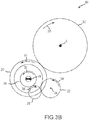
FIG. 2B illustrates a schematic view of a lubrication system, in accordance with various embodiments; -
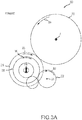
FIG. 3A illustrates a schematic view of an input gear train for a lubrication system, in accordance with various embodiments; -
FIG. 3B illustrates a schematic view of an input gear train for a lubrication system, in accordance with various embodiments; -
FIG. 4 illustrates a schematic view of an example sprag clutch assembly, in accordance with various embodiments; and -
FIG. 5 illustrates a method of lubricating a geared architecture, in accordance with various embodiments. - The detailed description of exemplary embodiments herein, and with reference to the accompanying drawings, together describe the exemplary embodiments by way of illustration and their best mode. While these exemplary embodiments are described in sufficient detail to enable those skilled in the art to practice the disclosures, it should be understood that other embodiments may be realized and that logical, chemical, and mechanical changes may be made without departing from the scope of the disclosures. Thus, the detailed description herein is presented for purposes of illustration only and not of limitation. For example, the steps recited in any of the method or process descriptions may be executed in any order and are not necessarily limited to the order presented. Furthermore, any reference to singular includes plural embodiments, and any reference to more than one component or step may include a singular embodiment or step. Also, any reference to attached, fixed, connected or the like may include permanent, removable, temporary, partial, full and/or any other possible attachment option. Additionally, any reference to without contact (or similar phrases) may also include reduced contact or minimal contact.
- As used herein, "aft" refers to the direction associated with the tail (e.g., the back end) of an aircraft, or generally, to the direction of exhaust of a gas turbine engine. As used herein, "forward" refers to the direction associated with the intake (e.g., the front end) of a gas turbine engine. The term "upstream" is used to refer to directions and positions located closer to the source than directions and positions referenced as "downstream."
- As used herein, "distal" refers to the direction outward, or generally, away from a reference component. As used herein, "proximate" refers to a direction inward, or generally, towards a reference component. A first component that is "radially outward" or "outboard" of a second component means that the first component is positioned at a greater distance away from a central longitudinal axis of the gas turbine engine. A first component that is "radially inward" or "inboard" of a second component means that the first component is positioned closer to the engine central longitudinal axis than the second component. The terminology "radially outward" and "radially inward" may also be used relative to references other than the engine central longitudinal axis.
- In various embodiments and with reference to
FIG. 1 , a gas turbine engine 20 is provided. Gas turbine engine 20 may be a two-spool turbofan that generally incorporates a fan section 22, acompressor section 24, a combustor section 26 and aturbine section 28. In operation, fan section 22 can drive air along a bypass flow-path B whilecompressor section 24 can drive air for compression and communication into combustor section 26 then expansion throughturbine section 28. Although depicted as a turbofan gas turbine engine 20 herein, it should be understood that the concepts described herein are not limited to use with turbofans as the teachings may be applied to other types of turbine engines including turbojet engines, a low-bypass turbofans, a high bypass turbofans, or any other gas turbine known to those skilled in the art including single spool and three-spool architectures. - Gas turbine engine 20 may generally comprise a
low speed spool 30 and a high speed spool 32 mounted for rotation about an engine central longitudinal axis A-A' relative to an engine static structure 36 via one or more bearing systems 38 (shown as bearing system 38-1 and bearing system 38-2 inFIG. 2 ). It should be understood that various bearing systems 38 at various locations may alternatively or additionally be provided, including for example, bearing system 38, bearing system 38-1, and bearing system 38-2. -
Low speed spool 30 may generally comprise aninner shaft 40 that interconnects a fan 42, a low pressure (or first) compressor section 44 (also referred to a low pressure compressor 44) and a low pressure (or first)turbine section 46.Inner shaft 40 may be connected to fan 42 through a gearedarchitecture 48 that can drive fan 42 at a lower speed thanlow speed spool 30.Geared architecture 48 may comprise agear assembly 60 enclosed within a gear housing 62.Gear assembly 60 couplesinner shaft 40 to a rotating fan structure which may comprise afan shaft 66. High speed spool 32 may comprise an outer shaft 50 that interconnects a high pressure compressor ("HPC") 52 (e.g., a second compressor section) and high pressure (or second) turbine section 54. A combustor 56 may be located between HPC 52 and high pressure turbine 54. Amid-turbine frame 57 of engine static structure 36 may be located generally between high pressure turbine 54 andlow pressure turbine 46.Mid-turbine frame 57 may support one or more bearing systems 38 inturbine section 28.Inner shaft 40 and outer shaft 50 may be concentric and rotate via bearing systems 38 about the engine central longitudinal axis A-A', which is collinear with their longitudinal axes. As used herein, a "high pressure" compressor or turbine experiences a higher pressure than a corresponding "low pressure" compressor or turbine. - The core airflow C may be compressed by
low pressure compressor 44 then HPC 52, mixed and burned with fuel in combustor 56, then expanded over high pressure turbine 54 andlow pressure turbine 46.Mid-turbine frame 57 includesairfoils 59 which are in the core airflow path.Low pressure turbine 46, and high pressure turbine 54 rotationally drive the respectivelow speed spool 30 and high speed spool 32 in response to the expansion. - In various embodiments, HPC 52 and
LPC 44 may comprise alternating rows of rotating rotors 64 and stationary stators 65. Stators may have a cantilevered configuration or a shrouded configuration. More specifically, a stator may comprise a stator vane, a casing support and a hub support. In this regard, a stator vane may be supported along an outer diameter by a casing support and along an inner diameter by a hub support. In contrast, a cantilevered stator may comprise a stator vane that is only retained and/or supported at the casing (e.g., along an outer diameter). - In various embodiments, rotors may be configured to compress and spin a fluid flow. Stators may be configured to receive and straighten the fluid flow. In operation, the fluid flow discharged from the trailing edge of stators may be straightened (e.g., the flow may be directed in a substantially parallel path to the centerline of the engine and/or HPC) to increase and/or improve the efficiency of the engine and, more specifically, to achieve maximum and/or near maximum compression and efficiency when the straightened air is compressed and spun by rotor 64.
- According to various embodiments and with combined reference to
FIGS. 2A ,2B ,3A , and3B , fan section 22 may further comprise alubrication system 200 driven by aninput gear train 300.Input gear train 300 is driven byshaft gear 302 and includesprimary gear train 206 andreverse gear train 208. In various embodiments,shaft gear 302 is disposed aboutfan shaft 66 which is driven by gearedarchitecture 48 during normal engine operating conditions. During normal engine operating conditions,low pressure turbine 46 drivesinner shaft 40 and, in turn,gear assembly 60 rotatesfan shaft 66 andshaft gear 302 in aforward direction 304. Rotatingfan shaft 66 in theforward direction 304 thereby drives fan 42 forward tending to produce thrust.Lubrication system 200 includesinput gear train 300 and comprises agear pump 202 which sends flow of a lubricant (e.g, via aconduit 204 or other suitable lubricant channel) to gearedarchitecture 48 tending thereby to prolong the operational life of gearedarchitecture 48. Inshaft gear 302 rotating in theforward direction 304,gear pump 202 is driven by primary gear train 206 (stippled components shown inFIG. 2A ). When gas turbine engine 20 is in a non-operating condition, airflow over fan 42 may tend to rotate fan 42 (i.e. a phenomenon known as windmilling) and in response drivefan shaft 66 and therebyshaft gear 302 in areverse direction 305. In response to the windmilling fan, reverse gear train 208 (stippled components shown inFIG. 2B ) drivesgear pump 202 and, in this regard,lubrication system 200 may supply lubricant to gearedarchitecture 48 irrespective of a rotational direction offan 44. In various embodiments, a pump, such asgear pump 202, may comprise any suitable rotary pump such as, for example, a vane pump, a screw pump, a centrifugal pump, g-rotor pump, and/or the like. - In various embodiments and as shown in
FIGs. 2A and3A ,input gear train 300 includes theprimary gear train 206 having aprimary gear 210 which is coupled tocommon shaft 212.Common shaft 212 is supported by bearingassembly 217 and coupled to forward clutch 214 (i.e., a first clutch) and reverse clutch 216 (i.e., a second clutch). Forward clutch 214 is coupled toforward shaft 218 which is supported by bearingassembly 215 and lies radially outward ofcommon shaft 212, in turn,common shaft 212supports bearing assembly 215.Forward shaft 218 supportsforward gear 220 which is disposed aboutcommon shaft 212 and is selectively coupled thereto by forward clutch 214 such thatforward gear 220 will rotate withcommon shaft 212 only in one desired direction.Forward gear 220 is coupled to pumpgear 222 which, in turn, is supported onpump shaft 224 which drivesgear pump 202. In normal operation, rotation of theshaft gear 302 in theforward direction 304 results in rotation of theprimary gear 210 andcommon shaft 212 in afirst direction 306 which tends to engage forward clutch 214 (as illustrated by vertical stripes). Engaging forward clutch 214 locksforward shaft 218 tocommon shaft 212 thereby transmitting rotation of thecommon shaft 212 to theforward gear 220 and causing forward gear 220 to rotate in thefirst direction 306.Forward gear 220 transmitstorque 238 fromcommon shaft 212 to pumpgear 222 thereby inducing drive rotation 308 (i.e., a unidirectional rotation) ofpump gear 222 andpump shaft 224 tending thereby to supply lubricant fromgear pump 202 to gearedarchitecture 48. In various embodiments,gear pump 202 may be configured to supply lubricant in response to a unidirectional rotation ofpump shaft 224 and driverotation 308 may therefore be a unidirectional rotation. Stated another way,gear pump 202 may not supply lubricant in response to a rotation ofpump shaft 224 in a directionopposite drive rotation 308 and may tend to be damaged by such a rotation. - In various embodiments, geared
architecture 48 includes asun gear 240 which is circumscribed by a plurality ofintermediate gears 242 supported by acarrier 244 and engaged with asurrounding ring gear 246. In various embodiments, each of theintermediate gears 242 may be supported by a journal bearing 248 coupled tocarrier 244. In various embodiments, each of thejournal bearings 248 tend to benefit from a constant flow of lubricant tending thereby to inhibit wear. It is therefore desirable to ensure a flow of lubricant during operation and during windmilling. It should be understood that, although a geared architecture for driving a fan is disclosed,lubrication system 200 may supply lubricant to any component benefiting from lubrication during windmilling or normal operation of a gas turbine engine. - In various embodiments and as shown in
FIGs. 2B and3B ,input gear train 300 includes thereverse gear train 208 having theprimary gear 210,common shaft 212, forward clutch 214, and reverse clutch 216.Reverse gear train 208 includes areverse shaft 226 radially outward ofcommon shaft 212 coupled to reverse clutch 216 and supported by bearingassembly 217.Reverse shaft 226 is further supported by reverseshaft bearing assembly 228 about the reverse shaft.Reverse shaft 226 supports areverse gear 230 which is disposed aboutcommon shaft 212 and selectively coupled thereto by reverse clutch 216 such that it will rotate withcommon shaft 212 only in one desired direction.Reverse gear 230 is coupled toidler gear 232 which is supported byidler shaft 234 andidler bearing 236.Idler gear 232 is coupled to pumpgear 222. In windmilling operation, rotation ofshaft gear 302 in thereverse direction 305 results in rotation of theprimary gear 210 andcommon shaft 212 in asecond direction 307 leaving forward clutch 214 unlocked andforward gear 220 idle. In response to rotation of common shaft andprimary gear 210 in the second direction,reverse clutch 216 is engaged (as illustrated by vertical stripes) lockingreverse shaft 226 tocommon shaft 212 thereby transmitting rotation of thecommon shaft 212 to thereverse gear 230 and causing thereverse gear 230 to rotate in thesecond direction 307. In response toreverse gear 230 rotating in thesecond direction 307 idler gear is caused to rotate in thefirst direction 306 and transmittorque 238 fromcommon shaft 212 to pumpgear 222 thereby inducingdrive rotation 308 ofpump gear 222 andpump shaft 224 tending thereby to supply lubricant fromgear pump 202 to gearedarchitecture 48. - As may be appreciated, all the gears of
input gear train 300 may be engaged with each other and will turn in all instances whereprimary gear 210 is driving rotation ofcommon shaft 212. However,forward gear 220 andreverse gear 230 are each selectively coupled tocommon shaft 212 by a corresponding clutch (forward clutch 214 and reverse clutch 216) at their corresponding shaft (forward shaft 218 and reverse shaft 226). Accordingly, only rotation ofcommon shaft 212 in the desired direction will be transmitted to the respective gear and shaft set which otherwise will idle over the common shaft and not transmit torque fromcommon shaft 212. In this regard, torque may be supplied to inducedrive rotation 308 forgear pump 202 irrespective of a rotational direction ofcommon shaft 212. - In various embodiments and with additional reference to
FIG. 4 forward clutch 214 and reverse clutch 216 may be an overrunning clutch design using a sprag configuration which may comprise aninner race 402 and anouter race 404 separated by an annular space 406. Within annular space 406 are a plurality ofsprags 408 each of which may be shaped such that the transmit power between theinner race 402 and theouter race 404 when rotating in one direction and allow independent rotation between the tworaces inner race 402 and theouter race 404 which may be utilized to transmit torque in one desired direction. It should be appreciated that although a sprag clutch is disclosed other clutch configurations may be used and are within the contemplation of this disclosure. - In various embodiments and with reference to
FIG. 5 , amethod 500 of lubricating a geared architecture such as gearedarchitecture 48 may comprise rotating a shaft gear in a forward direction and rotating a primary gear and common shaft in a first direction (step 502), locking a forward clutch in response to the rotating in the first direction and rotating a forward gear in the first direction (step 504), and generating a flow of lubricant in response to rotating the forward gear in the first direction (step 506).Method 500 may include rotating the shaft gear in a reverse direction and rotating the primary gear and the common shaft in a second direction, locking a reverse clutch in response to the rotating in the second direction and rotating a reverse gear in the second direction, and generating the flow of lubricant in response to rotating the reverse gear in the second direction (step 508).Method 500 may further include idling at least one of the forward gear or the reverse gear in response to rotating the common shaft (step 510). - Benefits, other advantages, and solutions to problems have been described herein with regard to specific embodiments. Furthermore, the connecting lines shown in the various figures contained herein are intended to represent exemplary functional relationships and/or physical couplings between the various elements. It should be noted that many alternative or additional functional relationships or physical connections may be present in a practical system. However, the benefits, advantages, solutions to problems, and any elements that may cause any benefit, advantage, or solution to occur or become more pronounced are not to be construed as critical, required, or essential features or elements of the disclosures.
- The scope of the disclosures is accordingly to be limited by nothing other than the appended claims, in which reference to an element in the singular is not intended to mean "one and only one" unless explicitly so stated, but rather "one or more." Moreover, where a phrase similar to "at least one of A, B, or C" is used in the claims, it is intended that the phrase be interpreted to mean that A alone may be present in an embodiment, B alone may be present in an embodiment, C alone may be present in an embodiment, or that any combination of the elements A, B and C may be present in a single embodiment; for example, A and B, A and C, B and C, or A and B and C. Different cross-hatching is used throughout the figures to denote different parts but not necessarily to denote the same or different materials.
- Systems, methods and apparatus are provided herein. In the detailed description herein, references to "one embodiment", "an embodiment", "an example embodiment", etc., indicate that the embodiment described may include a particular feature, structure, or characteristic, but every embodiment may not necessarily include the particular feature, structure, or characteristic. Moreover, such phrases are not necessarily referring to the same embodiment. Further, when a particular feature, structure, or characteristic is described in connection with an embodiment, it is submitted that it is within the knowledge of one skilled in the art to affect such feature, structure, or characteristic in connection with other embodiments whether or not explicitly described. After reading the description, it will be apparent to one skilled in the relevant art(s) how to implement the disclosure in alternative embodiment
- Furthermore, no element, component, or method step in the present disclosure is intended to be dedicated to the public regardless of whether the element, component, or method step is explicitly recited in the claims. No claim element is intended to invoke 35 U.S.C. 112(f) unless the element is expressly recited using the phrase "means for." As used herein, the terms "comprises", "comprising", or any other variation thereof, are intended to cover a non-exclusive inclusion, such that a process, method, article, or apparatus that comprises a list of elements does not include only those elements but may include other elements not expressly listed or inherent to such process, method, article, or apparatus.
Claims (13)
- A lubrication system comprising;
a shaft including a shaft gear;
a pump configured to supply a flow of lubricant to a component benefiting from lubrication; and
an input gear train coupled to the shaft gear and configured to drive the pump with a unidirectional rotation in response to a forward rotation and a reverse rotation of the shaft gear. - The lubrication system of claim 1, wherein the input gear train further comprises a primary gear coupled to a common shaft.
- The lubrication system of claim 2, wherein the input gear train further comprises a forward shaft and a forward gear about the common shaft, wherein the forward gear is coupled to the forward shaft.
- The lubrication system of claim 3, wherein the input gear train further comprises a reverse shaft and a reverse gear about the common shaft, wherein the reverse gear is coupled to the reverse shaft.
- The lubrication system of claim 4, wherein the input gear train further comprises a forward clutch coupled to the forward shaft and a reverse clutch coupled to the reverse shaft.
- The lubrication system of claim 5, wherein the forward clutch and the reverse clutch are selectively coupled to the common shaft, wherein the forward clutch is configured to lock in response to rotating the common shaft in a first direction, wherein the reverse clutch is configured to lock in response to rotating the common shaft in a second direction.
- The lubrication system of claim 6, wherein the input gear train further comprises an idler gear supported by an idler shaft and coupled to the reverse gear.
- The lubrication system of claim 7, wherein the input gear train further comprises a pump gear coupled to the forward gear and the idler gear, the pump gear supported by a pump shaft coupled to the pump.
- A gas turbine engine comprising:a compressor section configured to compress a gas;a combustor section aft of the compressor section configured to combust the gas;a turbine section aft of the combustor section configured to extract work from the combusted gas; anda lubrication system as claimed in any preceding claim.
- The lubrication system of claim 9, wherein the shaft is in communication with a fan, wherein the shaft rotates in a reverse direction in response to a windmilling of the fan, wherein the component comprises a geared architecture including at least one journal bearing.
- A method of lubricating a geared architecture, the method comprising:rotating a shaft gear in a forward direction and rotating a primary gear and common shaft in a first direction;locking a forward clutch in response to the rotating in the first direction and rotating a forward gear in the first direction; andgenerating a flow of lubricant in response to rotating the forward gear in the first direction.
- The method of claim 11, further comprising rotating the shaft gear in a reverse direction and rotating the primary gear and the common shaft in a second direction;
unlocking the forward clutch and locking a reverse clutch in response to the rotating in the second direction and rotating a reverse gear in the second direction; and
generating the flow of lubricant in response to rotating the reverse gear in the second direction. - The method of claim 12, including idling at least one of the forward gear or the reverse gear in response to rotating the common shaft.
Applications Claiming Priority (1)
| Application Number | Priority Date | Filing Date | Title |
|---|---|---|---|
| US16/001,699 US11441450B2 (en) | 2018-06-06 | 2018-06-06 | Dual direction windmill pump for geared turbofan engines |
Publications (2)
| Publication Number | Publication Date |
|---|---|
| EP3578780A1 true EP3578780A1 (en) | 2019-12-11 |
| EP3578780B1 EP3578780B1 (en) | 2023-08-02 |
Family
ID=67060243
Family Applications (1)
| Application Number | Title | Priority Date | Filing Date |
|---|---|---|---|
| EP19178502.1A Active EP3578780B1 (en) | 2018-06-06 | 2019-06-05 | Dual direction windmill pump for geared turbofan engines |
Country Status (3)
| Country | Link |
|---|---|
| US (1) | US11441450B2 (en) |
| EP (1) | EP3578780B1 (en) |
| JP (1) | JP2019211080A (en) |
Cited By (1)
| Publication number | Priority date | Publication date | Assignee | Title |
|---|---|---|---|---|
| FR3109963A1 (en) * | 2020-05-06 | 2021-11-12 | Safran Aircraft Engines | TURBOMACHINE BLOWER REDUCER LUBRICATION MODULE IN THE BLOWER AUTOROTATION PHASE |
Families Citing this family (10)
| Publication number | Priority date | Publication date | Assignee | Title |
|---|---|---|---|---|
| WO2021223910A1 (en) * | 2020-05-04 | 2021-11-11 | Nuovo Pignone Tecnologie - S.R.L. | Gas turbines in mechanical drive applications and operating methods thereof |
| US11519338B1 (en) * | 2022-01-19 | 2022-12-06 | Raytheon Technologies Corporation | Gear train with variable input direction of rotation and constant output direction of rotation |
| US12320418B2 (en) * | 2022-06-22 | 2025-06-03 | General Electric Company | Gearbox assembly with lubricant extraction volume ratio |
| US12326115B2 (en) * | 2022-06-22 | 2025-06-10 | General Electric Company | Gearbox assembly with lubricant extraction volume ratio |
| US12516627B2 (en) | 2022-07-27 | 2026-01-06 | General Electric Company | Gas turbine engine |
| US12584446B2 (en) | 2023-06-21 | 2026-03-24 | General Electric Company | Unidirectional fan brake for a gas turbine engine |
| US12276333B2 (en) * | 2023-06-21 | 2025-04-15 | General Electric Company | Gearbox assembly lubrication system for a turbine engine |
| US12510002B2 (en) | 2023-07-12 | 2025-12-30 | General Electric Company | Lubrication system for a turbine engine |
| US12228042B1 (en) * | 2023-08-04 | 2025-02-18 | General Electric Company | Lubrication system for a turbine engine |
| US12492649B2 (en) | 2024-05-06 | 2025-12-09 | General Electric Company | Lubrication system and methods of lubricating a gearbox assembly |
Citations (3)
| Publication number | Priority date | Publication date | Assignee | Title |
|---|---|---|---|---|
| WO2015060912A2 (en) * | 2013-09-19 | 2015-04-30 | United Technologies Corporation | Dual direction windmill pump for geared turbofan engine |
| EP3171055A1 (en) * | 2015-11-23 | 2017-05-24 | United Technologies Corporation | Near zero velocity lubrication system for a turbine engine |
| EP3543483A1 (en) * | 2018-03-23 | 2019-09-25 | United Technologies Corporation | Windmill lubrication gear train for lubricant system in a geared gas turbine engine |
Family Cites Families (5)
| Publication number | Priority date | Publication date | Assignee | Title |
|---|---|---|---|---|
| US5349814A (en) * | 1993-02-03 | 1994-09-27 | General Electric Company | Air-start assembly and method |
| US10408133B2 (en) * | 2014-10-03 | 2019-09-10 | Pratt & Whitney Canada Corp. | Accessory drive system for a gas turbine engine |
| US10329955B2 (en) | 2016-01-27 | 2019-06-25 | Pratt & Whitney Canada Corp. | Oil system for turbine engine and related method |
| JP2017144872A (en) * | 2016-02-17 | 2017-08-24 | トヨタ自動車株式会社 | Vehicle drive device |
| JP2017219049A (en) * | 2016-06-02 | 2017-12-14 | 日産自動車株式会社 | Oil pump |
-
2018
- 2018-06-06 US US16/001,699 patent/US11441450B2/en active Active
-
2019
- 2019-05-30 JP JP2019100830A patent/JP2019211080A/en active Pending
- 2019-06-05 EP EP19178502.1A patent/EP3578780B1/en active Active
Patent Citations (3)
| Publication number | Priority date | Publication date | Assignee | Title |
|---|---|---|---|---|
| WO2015060912A2 (en) * | 2013-09-19 | 2015-04-30 | United Technologies Corporation | Dual direction windmill pump for geared turbofan engine |
| EP3171055A1 (en) * | 2015-11-23 | 2017-05-24 | United Technologies Corporation | Near zero velocity lubrication system for a turbine engine |
| EP3543483A1 (en) * | 2018-03-23 | 2019-09-25 | United Technologies Corporation | Windmill lubrication gear train for lubricant system in a geared gas turbine engine |
Cited By (1)
| Publication number | Priority date | Publication date | Assignee | Title |
|---|---|---|---|---|
| FR3109963A1 (en) * | 2020-05-06 | 2021-11-12 | Safran Aircraft Engines | TURBOMACHINE BLOWER REDUCER LUBRICATION MODULE IN THE BLOWER AUTOROTATION PHASE |
Also Published As
| Publication number | Publication date |
|---|---|
| US20190376416A1 (en) | 2019-12-12 |
| JP2019211080A (en) | 2019-12-12 |
| US11441450B2 (en) | 2022-09-13 |
| EP3578780B1 (en) | 2023-08-02 |
Similar Documents
| Publication | Publication Date | Title |
|---|---|---|
| US11441450B2 (en) | Dual direction windmill pump for geared turbofan engines | |
| USRE50848E1 (en) | Gas turbine engine assembly and method of assembling same | |
| US10533446B2 (en) | Alternative W-seal groove arrangement | |
| US10196926B2 (en) | Lubricating a rotating component during forward and/or reverse rotation | |
| EP3163034B1 (en) | Gas turbine engine comprising two pumps for lubrication in both directions of rotation of the fan | |
| US9896969B2 (en) | Zero or low leakage oil transfer bearing | |
| US20120260623A1 (en) | Coupling shaft for gas turbine fan drive gear system | |
| EP3722633A1 (en) | Vibration isolator assembly | |
| US12385442B1 (en) | Gearbox assembly for a turbine engine | |
| EP3730828B1 (en) | Dynamic sleeve seal fittings | |
| US11230927B2 (en) | Vane airfoil shapes for embedded members | |
| EP4166762A2 (en) | Radial outward bearing support for a rotating structure of a turbine engine | |
| US11371632B2 (en) | Compliant jumper tube fitting | |
| US12270336B1 (en) | Fan drive gear system rotating oil baffle | |
| US20200032669A1 (en) | Shrouded blade assemblies | |
| US12584446B2 (en) | Unidirectional fan brake for a gas turbine engine | |
| US12590562B2 (en) | Component mounting and drive in a geared turbofan architecture | |
| US12292110B1 (en) | Component mounting and drive in a geared turbofan architecture | |
| EP4545754A1 (en) | Vane outer shroud undercut groove | |
| EP2930304B1 (en) | High pressure compressor thermal shield apparatus and system |
Legal Events
| Date | Code | Title | Description |
|---|---|---|---|
| PUAI | Public reference made under article 153(3) epc to a published international application that has entered the european phase |
Free format text: ORIGINAL CODE: 0009012 |
|
| STAA | Information on the status of an ep patent application or granted ep patent |
Free format text: STATUS: THE APPLICATION HAS BEEN PUBLISHED |
|
| AK | Designated contracting states |
Kind code of ref document: A1 Designated state(s): AL AT BE BG CH CY CZ DE DK EE ES FI FR GB GR HR HU IE IS IT LI LT LU LV MC MK MT NL NO PL PT RO RS SE SI SK SM TR |
|
| AX | Request for extension of the european patent |
Extension state: BA ME |
|
| STAA | Information on the status of an ep patent application or granted ep patent |
Free format text: STATUS: REQUEST FOR EXAMINATION WAS MADE |
|
| 17P | Request for examination filed |
Effective date: 20200611 |
|
| RBV | Designated contracting states (corrected) |
Designated state(s): AL AT BE BG CH CY CZ DE DK EE ES FI FR GB GR HR HU IE IS IT LI LT LU LV MC MK MT NL NO PL PT RO RS SE SI SK SM TR |
|
| RAP1 | Party data changed (applicant data changed or rights of an application transferred) |
Owner name: RAYTHEON TECHNOLOGIES CORPORATION |
|
| STAA | Information on the status of an ep patent application or granted ep patent |
Free format text: STATUS: EXAMINATION IS IN PROGRESS |
|
| 17Q | First examination report despatched |
Effective date: 20210614 |
|
| GRAP | Despatch of communication of intention to grant a patent |
Free format text: ORIGINAL CODE: EPIDOSNIGR1 |
|
| STAA | Information on the status of an ep patent application or granted ep patent |
Free format text: STATUS: GRANT OF PATENT IS INTENDED |
|
| INTG | Intention to grant announced |
Effective date: 20230228 |
|
| GRAS | Grant fee paid |
Free format text: ORIGINAL CODE: EPIDOSNIGR3 |
|
| GRAA | (expected) grant |
Free format text: ORIGINAL CODE: 0009210 |
|
| STAA | Information on the status of an ep patent application or granted ep patent |
Free format text: STATUS: THE PATENT HAS BEEN GRANTED |
|
| AK | Designated contracting states |
Kind code of ref document: B1 Designated state(s): AL AT BE BG CH CY CZ DE DK EE ES FI FR GB GR HR HU IE IS IT LI LT LU LV MC MK MT NL NO PL PT RO RS SE SI SK SM TR |
|
| REG | Reference to a national code |
Ref country code: GB Ref legal event code: FG4D |
|
| REG | Reference to a national code |
Ref country code: CH Ref legal event code: EP |
|
| REG | Reference to a national code |
Ref country code: DE Ref legal event code: R096 Ref document number: 602019033878 Country of ref document: DE |
|
| REG | Reference to a national code |
Ref country code: IE Ref legal event code: FG4D |
|
| RAP4 | Party data changed (patent owner data changed or rights of a patent transferred) |
Owner name: RTX CORPORATION |
|
| REG | Reference to a national code |
Ref country code: LT Ref legal event code: MG9D |
|
| REG | Reference to a national code |
Ref country code: NL Ref legal event code: MP Effective date: 20230802 |
|
| REG | Reference to a national code |
Ref country code: AT Ref legal event code: MK05 Ref document number: 1595005 Country of ref document: AT Kind code of ref document: T Effective date: 20230802 |
|
| PG25 | Lapsed in a contracting state [announced via postgrant information from national office to epo] |
Ref country code: GR Free format text: LAPSE BECAUSE OF FAILURE TO SUBMIT A TRANSLATION OF THE DESCRIPTION OR TO PAY THE FEE WITHIN THE PRESCRIBED TIME-LIMIT Effective date: 20231103 |
|
| PG25 | Lapsed in a contracting state [announced via postgrant information from national office to epo] |
Ref country code: IS Free format text: LAPSE BECAUSE OF FAILURE TO SUBMIT A TRANSLATION OF THE DESCRIPTION OR TO PAY THE FEE WITHIN THE PRESCRIBED TIME-LIMIT Effective date: 20231202 |
|
| PG25 | Lapsed in a contracting state [announced via postgrant information from national office to epo] |
Ref country code: SE Free format text: LAPSE BECAUSE OF FAILURE TO SUBMIT A TRANSLATION OF THE DESCRIPTION OR TO PAY THE FEE WITHIN THE PRESCRIBED TIME-LIMIT Effective date: 20230802 Ref country code: RS Free format text: LAPSE BECAUSE OF FAILURE TO SUBMIT A TRANSLATION OF THE DESCRIPTION OR TO PAY THE FEE WITHIN THE PRESCRIBED TIME-LIMIT Effective date: 20230802 Ref country code: PT Free format text: LAPSE BECAUSE OF FAILURE TO SUBMIT A TRANSLATION OF THE DESCRIPTION OR TO PAY THE FEE WITHIN THE PRESCRIBED TIME-LIMIT Effective date: 20231204 Ref country code: NO Free format text: LAPSE BECAUSE OF FAILURE TO SUBMIT A TRANSLATION OF THE DESCRIPTION OR TO PAY THE FEE WITHIN THE PRESCRIBED TIME-LIMIT Effective date: 20231102 Ref country code: NL Free format text: LAPSE BECAUSE OF FAILURE TO SUBMIT A TRANSLATION OF THE DESCRIPTION OR TO PAY THE FEE WITHIN THE PRESCRIBED TIME-LIMIT Effective date: 20230802 Ref country code: LV Free format text: LAPSE BECAUSE OF FAILURE TO SUBMIT A TRANSLATION OF THE DESCRIPTION OR TO PAY THE FEE WITHIN THE PRESCRIBED TIME-LIMIT Effective date: 20230802 Ref country code: LT Free format text: LAPSE BECAUSE OF FAILURE TO SUBMIT A TRANSLATION OF THE DESCRIPTION OR TO PAY THE FEE WITHIN THE PRESCRIBED TIME-LIMIT Effective date: 20230802 Ref country code: IS Free format text: LAPSE BECAUSE OF FAILURE TO SUBMIT A TRANSLATION OF THE DESCRIPTION OR TO PAY THE FEE WITHIN THE PRESCRIBED TIME-LIMIT Effective date: 20231202 Ref country code: HR Free format text: LAPSE BECAUSE OF FAILURE TO SUBMIT A TRANSLATION OF THE DESCRIPTION OR TO PAY THE FEE WITHIN THE PRESCRIBED TIME-LIMIT Effective date: 20230802 Ref country code: GR Free format text: LAPSE BECAUSE OF FAILURE TO SUBMIT A TRANSLATION OF THE DESCRIPTION OR TO PAY THE FEE WITHIN THE PRESCRIBED TIME-LIMIT Effective date: 20231103 Ref country code: FI Free format text: LAPSE BECAUSE OF FAILURE TO SUBMIT A TRANSLATION OF THE DESCRIPTION OR TO PAY THE FEE WITHIN THE PRESCRIBED TIME-LIMIT Effective date: 20230802 Ref country code: AT Free format text: LAPSE BECAUSE OF FAILURE TO SUBMIT A TRANSLATION OF THE DESCRIPTION OR TO PAY THE FEE WITHIN THE PRESCRIBED TIME-LIMIT Effective date: 20230802 |
|
| PG25 | Lapsed in a contracting state [announced via postgrant information from national office to epo] |
Ref country code: PL Free format text: LAPSE BECAUSE OF FAILURE TO SUBMIT A TRANSLATION OF THE DESCRIPTION OR TO PAY THE FEE WITHIN THE PRESCRIBED TIME-LIMIT Effective date: 20230802 |
|
| PG25 | Lapsed in a contracting state [announced via postgrant information from national office to epo] |
Ref country code: ES Free format text: LAPSE BECAUSE OF FAILURE TO SUBMIT A TRANSLATION OF THE DESCRIPTION OR TO PAY THE FEE WITHIN THE PRESCRIBED TIME-LIMIT Effective date: 20230802 |
|
| PG25 | Lapsed in a contracting state [announced via postgrant information from national office to epo] |
Ref country code: SM Free format text: LAPSE BECAUSE OF FAILURE TO SUBMIT A TRANSLATION OF THE DESCRIPTION OR TO PAY THE FEE WITHIN THE PRESCRIBED TIME-LIMIT Effective date: 20230802 Ref country code: RO Free format text: LAPSE BECAUSE OF FAILURE TO SUBMIT A TRANSLATION OF THE DESCRIPTION OR TO PAY THE FEE WITHIN THE PRESCRIBED TIME-LIMIT Effective date: 20230802 Ref country code: ES Free format text: LAPSE BECAUSE OF FAILURE TO SUBMIT A TRANSLATION OF THE DESCRIPTION OR TO PAY THE FEE WITHIN THE PRESCRIBED TIME-LIMIT Effective date: 20230802 Ref country code: EE Free format text: LAPSE BECAUSE OF FAILURE TO SUBMIT A TRANSLATION OF THE DESCRIPTION OR TO PAY THE FEE WITHIN THE PRESCRIBED TIME-LIMIT Effective date: 20230802 Ref country code: DK Free format text: LAPSE BECAUSE OF FAILURE TO SUBMIT A TRANSLATION OF THE DESCRIPTION OR TO PAY THE FEE WITHIN THE PRESCRIBED TIME-LIMIT Effective date: 20230802 Ref country code: CZ Free format text: LAPSE BECAUSE OF FAILURE TO SUBMIT A TRANSLATION OF THE DESCRIPTION OR TO PAY THE FEE WITHIN THE PRESCRIBED TIME-LIMIT Effective date: 20230802 Ref country code: SK Free format text: LAPSE BECAUSE OF FAILURE TO SUBMIT A TRANSLATION OF THE DESCRIPTION OR TO PAY THE FEE WITHIN THE PRESCRIBED TIME-LIMIT Effective date: 20230802 |
|
| REG | Reference to a national code |
Ref country code: DE Ref legal event code: R097 Ref document number: 602019033878 Country of ref document: DE |
|
| PG25 | Lapsed in a contracting state [announced via postgrant information from national office to epo] |
Ref country code: IT Free format text: LAPSE BECAUSE OF FAILURE TO SUBMIT A TRANSLATION OF THE DESCRIPTION OR TO PAY THE FEE WITHIN THE PRESCRIBED TIME-LIMIT Effective date: 20230802 |
|
| PLBE | No opposition filed within time limit |
Free format text: ORIGINAL CODE: 0009261 |
|
| STAA | Information on the status of an ep patent application or granted ep patent |
Free format text: STATUS: NO OPPOSITION FILED WITHIN TIME LIMIT |
|
| 26N | No opposition filed |
Effective date: 20240503 |
|
| PG25 | Lapsed in a contracting state [announced via postgrant information from national office to epo] |
Ref country code: SI Free format text: LAPSE BECAUSE OF FAILURE TO SUBMIT A TRANSLATION OF THE DESCRIPTION OR TO PAY THE FEE WITHIN THE PRESCRIBED TIME-LIMIT Effective date: 20230802 |
|
| PG25 | Lapsed in a contracting state [announced via postgrant information from national office to epo] |
Ref country code: BG Free format text: LAPSE BECAUSE OF FAILURE TO SUBMIT A TRANSLATION OF THE DESCRIPTION OR TO PAY THE FEE WITHIN THE PRESCRIBED TIME-LIMIT Effective date: 20230802 |
|
| PG25 | Lapsed in a contracting state [announced via postgrant information from national office to epo] |
Ref country code: BG Free format text: LAPSE BECAUSE OF FAILURE TO SUBMIT A TRANSLATION OF THE DESCRIPTION OR TO PAY THE FEE WITHIN THE PRESCRIBED TIME-LIMIT Effective date: 20230802 |
|
| PG25 | Lapsed in a contracting state [announced via postgrant information from national office to epo] |
Ref country code: MC Free format text: LAPSE BECAUSE OF FAILURE TO SUBMIT A TRANSLATION OF THE DESCRIPTION OR TO PAY THE FEE WITHIN THE PRESCRIBED TIME-LIMIT Effective date: 20230802 |
|
| REG | Reference to a national code |
Ref country code: CH Ref legal event code: PL |
|
| PG25 | Lapsed in a contracting state [announced via postgrant information from national office to epo] |
Ref country code: LU Free format text: LAPSE BECAUSE OF NON-PAYMENT OF DUE FEES Effective date: 20240605 |
|
| PG25 | Lapsed in a contracting state [announced via postgrant information from national office to epo] |
Ref country code: IE Free format text: LAPSE BECAUSE OF NON-PAYMENT OF DUE FEES Effective date: 20240605 |
|
| PG25 | Lapsed in a contracting state [announced via postgrant information from national office to epo] |
Ref country code: BE Free format text: LAPSE BECAUSE OF NON-PAYMENT OF DUE FEES Effective date: 20240630 Ref country code: CH Free format text: LAPSE BECAUSE OF NON-PAYMENT OF DUE FEES Effective date: 20240630 |
|
| REG | Reference to a national code |
Ref country code: BE Ref legal event code: MM Effective date: 20240630 |
|
| PGFP | Annual fee paid to national office [announced via postgrant information from national office to epo] |
Ref country code: DE Payment date: 20250520 Year of fee payment: 7 |
|
| PGFP | Annual fee paid to national office [announced via postgrant information from national office to epo] |
Ref country code: GB Payment date: 20250520 Year of fee payment: 7 |
|
| PGFP | Annual fee paid to national office [announced via postgrant information from national office to epo] |
Ref country code: FR Payment date: 20250520 Year of fee payment: 7 |
|
| REG | Reference to a national code |
Ref country code: DE Ref legal event code: R081 Ref document number: 602019033878 Country of ref document: DE Owner name: RTX CORPORATION (N.D.GES.D. STAATES DELAWARE),, US Free format text: FORMER OWNER: RAYTHEON TECHNOLOGIES CORPORATION, FARMINGTON, CT, US |
|
| PG25 | Lapsed in a contracting state [announced via postgrant information from national office to epo] |
Ref country code: CY Free format text: LAPSE BECAUSE OF FAILURE TO SUBMIT A TRANSLATION OF THE DESCRIPTION OR TO PAY THE FEE WITHIN THE PRESCRIBED TIME-LIMIT; INVALID AB INITIO Effective date: 20190605 |
|
| P01 | Opt-out of the competence of the unified patent court (upc) registered |
Free format text: CASE NUMBER: UPC_APP_0019304_3578780/2025 Effective date: 20251223 |
|
| PG25 | Lapsed in a contracting state [announced via postgrant information from national office to epo] |
Ref country code: HU Free format text: LAPSE BECAUSE OF FAILURE TO SUBMIT A TRANSLATION OF THE DESCRIPTION OR TO PAY THE FEE WITHIN THE PRESCRIBED TIME-LIMIT; INVALID AB INITIO Effective date: 20190605 |