EP3578758A1 - Turbine airfoil, corresponding gas turbine engine and method of making - Google Patents
Turbine airfoil, corresponding gas turbine engine and method of making Download PDFInfo
- Publication number
- EP3578758A1 EP3578758A1 EP19178515.3A EP19178515A EP3578758A1 EP 3578758 A1 EP3578758 A1 EP 3578758A1 EP 19178515 A EP19178515 A EP 19178515A EP 3578758 A1 EP3578758 A1 EP 3578758A1
- Authority
- EP
- European Patent Office
- Prior art keywords
- turbine
- transition
- shelf portion
- pocket portion
- recited
- Prior art date
- Legal status (The legal status is an assumption and is not a legal conclusion. Google has not performed a legal analysis and makes no representation as to the accuracy of the status listed.)
- Withdrawn
Links
- 238000004519 manufacturing process Methods 0.000 title claims abstract description 6
- 230000007704 transition Effects 0.000 claims abstract description 55
- 238000001816 cooling Methods 0.000 claims abstract description 19
- 238000000034 method Methods 0.000 claims description 6
- 239000011248 coating agent Substances 0.000 claims description 3
- 238000000576 coating method Methods 0.000 claims description 3
- 239000007789 gas Substances 0.000 description 32
- 238000004891 communication Methods 0.000 description 5
- 239000000446 fuel Substances 0.000 description 5
- 230000015572 biosynthetic process Effects 0.000 description 2
- 239000000463 material Substances 0.000 description 2
- 230000009467 reduction Effects 0.000 description 2
- 230000003068 static effect Effects 0.000 description 2
- 230000004308 accommodation Effects 0.000 description 1
- 230000015556 catabolic process Effects 0.000 description 1
- 230000008859 change Effects 0.000 description 1
- 238000002485 combustion reaction Methods 0.000 description 1
- 230000006835 compression Effects 0.000 description 1
- 238000007906 compression Methods 0.000 description 1
- 238000012937 correction Methods 0.000 description 1
- 238000006731 degradation reaction Methods 0.000 description 1
- 230000003628 erosive effect Effects 0.000 description 1
- 238000003754 machining Methods 0.000 description 1
- 230000007246 mechanism Effects 0.000 description 1
- 238000012986 modification Methods 0.000 description 1
- 230000004048 modification Effects 0.000 description 1
- 210000003739 neck Anatomy 0.000 description 1
- 230000003647 oxidation Effects 0.000 description 1
- 238000007254 oxidation reaction Methods 0.000 description 1
- 230000002028 premature Effects 0.000 description 1
- 230000008569 process Effects 0.000 description 1
- 230000001141 propulsive effect Effects 0.000 description 1
- 230000004044 response Effects 0.000 description 1
- 238000009420 retrofitting Methods 0.000 description 1
- 238000012546 transfer Methods 0.000 description 1
Images



Classifications
-
- F—MECHANICAL ENGINEERING; LIGHTING; HEATING; WEAPONS; BLASTING
- F01—MACHINES OR ENGINES IN GENERAL; ENGINE PLANTS IN GENERAL; STEAM ENGINES
- F01D—NON-POSITIVE DISPLACEMENT MACHINES OR ENGINES, e.g. STEAM TURBINES
- F01D5/00—Blades; Blade-carrying members; Heating, heat-insulating, cooling or antivibration means on the blades or the members
- F01D5/12—Blades
- F01D5/14—Form or construction
- F01D5/20—Specially-shaped blade tips to seal space between tips and stator
-
- F—MECHANICAL ENGINEERING; LIGHTING; HEATING; WEAPONS; BLASTING
- F01—MACHINES OR ENGINES IN GENERAL; ENGINE PLANTS IN GENERAL; STEAM ENGINES
- F01D—NON-POSITIVE DISPLACEMENT MACHINES OR ENGINES, e.g. STEAM TURBINES
- F01D5/00—Blades; Blade-carrying members; Heating, heat-insulating, cooling or antivibration means on the blades or the members
- F01D5/12—Blades
- F01D5/14—Form or construction
- F01D5/147—Construction, i.e. structural features, e.g. of weight-saving hollow blades
-
- F—MECHANICAL ENGINEERING; LIGHTING; HEATING; WEAPONS; BLASTING
- F01—MACHINES OR ENGINES IN GENERAL; ENGINE PLANTS IN GENERAL; STEAM ENGINES
- F01D—NON-POSITIVE DISPLACEMENT MACHINES OR ENGINES, e.g. STEAM TURBINES
- F01D5/00—Blades; Blade-carrying members; Heating, heat-insulating, cooling or antivibration means on the blades or the members
- F01D5/12—Blades
- F01D5/14—Form or construction
- F01D5/18—Hollow blades, i.e. blades with cooling or heating channels or cavities; Heating, heat-insulating or cooling means on blades
- F01D5/187—Convection cooling
-
- F—MECHANICAL ENGINEERING; LIGHTING; HEATING; WEAPONS; BLASTING
- F05—INDEXING SCHEMES RELATING TO ENGINES OR PUMPS IN VARIOUS SUBCLASSES OF CLASSES F01-F04
- F05D—INDEXING SCHEME FOR ASPECTS RELATING TO NON-POSITIVE-DISPLACEMENT MACHINES OR ENGINES, GAS-TURBINES OR JET-PROPULSION PLANTS
- F05D2230/00—Manufacture
- F05D2230/20—Manufacture essentially without removing material
- F05D2230/21—Manufacture essentially without removing material by casting
-
- F—MECHANICAL ENGINEERING; LIGHTING; HEATING; WEAPONS; BLASTING
- F05—INDEXING SCHEMES RELATING TO ENGINES OR PUMPS IN VARIOUS SUBCLASSES OF CLASSES F01-F04
- F05D—INDEXING SCHEME FOR ASPECTS RELATING TO NON-POSITIVE-DISPLACEMENT MACHINES OR ENGINES, GAS-TURBINES OR JET-PROPULSION PLANTS
- F05D2240/00—Components
- F05D2240/20—Rotors
- F05D2240/30—Characteristics of rotor blades, i.e. of any element transforming dynamic fluid energy to or from rotational energy and being attached to a rotor
- F05D2240/307—Characteristics of rotor blades, i.e. of any element transforming dynamic fluid energy to or from rotational energy and being attached to a rotor related to the tip of a rotor blade
-
- F—MECHANICAL ENGINEERING; LIGHTING; HEATING; WEAPONS; BLASTING
- F05—INDEXING SCHEMES RELATING TO ENGINES OR PUMPS IN VARIOUS SUBCLASSES OF CLASSES F01-F04
- F05D—INDEXING SCHEME FOR ASPECTS RELATING TO NON-POSITIVE-DISPLACEMENT MACHINES OR ENGINES, GAS-TURBINES OR JET-PROPULSION PLANTS
- F05D2260/00—Function
- F05D2260/20—Heat transfer, e.g. cooling
- F05D2260/202—Heat transfer, e.g. cooling by film cooling
Definitions
- a gas turbine engine typically includes a fan section, a compressor section, a combustor section and a turbine section. Air entering the compressor section is compressed and delivered into the combustion section where it is mixed with fuel and ignited to generate a high-energy exhaust gas flow. The high-energy exhaust gas flow expands through the turbine section to drive the compressor and the fan section.
- the compressor section typically includes low and high pressure compressors, and the turbine section includes low and high pressure turbines.
- Turbine blades operate in an environment of high temperatures and pressures. High heat loads on the turbine blades necessitate the use of a cooling airflow along surfaces of the turbine blade including its tip. Erosion and oxidation of the turbine blade at the tip can cause premature degradation that impacts performance, and can require replacement.
- Turbine engine manufactures continue to seek improvements to engine performance including improvements to thermal and propulsive efficiencies.
- a turbine airfoil for a gas turbine engine includes among other possible things, a tip portion including a pocket portion that transitions into a shelf portion and a plurality of cooling holes for communicating cooing airflow to at least one of the pocket portion and the shelf portion.
- the tip portion includes an uninterrupted suction side wall with a width that varies from a leading edge toward a trailing edge.
- a transition between the pocket portion and the shelf portion and the width of the suction side wall is greater aft of the transition than forward of the transition.
- the tip portion includes a pressure side wall that extends from the leading edge to the shelf portion.
- the shelf portion includes an aft end forward of a trailing edge.
- a transition is included between the pocket portion and the shelf portion.
- the transition includes a transition width between a suction side wall and a pressure side wall that is less than at least one of a maximum width of the pocket portion and a maximum width of the shelf portion.
- a first bottom surface in the pocket portion and a second bottom surface in the shelf portion is included, and the first bottom surface and the second bottom surfaces are disposed at different depths.
- the first bottom surface is at a first depth greater than a second depth of the second bottom surface.
- a sloped transition surface between the first bottom surface and the second bottom surface is included.
- a step transition is between the first bottom surface and the second bottom surface.
- the pocket portion includes a length along a camber line that is different than a length of the shelf portion along the camber line.
- the shelf portion includes a width transverse to a camber line that is less than a width of the pocket portion transverse to the camber line.
- a coating is included on surfaces of the pocket portion and the shelf portion.
- a gas turbine engine includes among other possible things, a turbine section that includes a plurality of turbine blades. At least one of the plurality of turbine blades includes a tip portion including a pocket portion that transitions into a shelf portion and a plurality of cooling holes for communicating cooing airflow to at least one of the pocket portion and the shelf portion.
- the tip portion includes an uninterrupted suction side wall with a width that varies from a leading edge toward a trailing edge, and a pressure side wall that extends from the leading edge to the shelf portion.
- a transition is included between the pocket portion and the shelf portion.
- the transition includes a transition width between a suction side wall and a pressure side wall that is less than at least one of a maximum width of the pocket portion and a maximum width of the shelf portion.
- a first bottom surface is included in the pocket portion.
- a second bottom surface in the shelf portion and the first bottom surface and the second bottom surfaces are disposed at different depths.
- a method of making an airfoil for a turbine section of a gas turbine engine includes, among other possible things, forming an airfoil to include a pressure side and suction side extending between a leading edge, trailing edge a tip and a root; forming the tip to include a pocket portion; and forming a shelf portion aft of the pocket portion.
- the shelf portion opens at least partially into the pocket portion and a pressure side wall varies in width between the pocket portion and the shelf portion.
- forming a transition portion between the pocket portion and the shelf portion is included.
- the transition portion includes an open width less than a maximum width of the pocket portion.
- the pocket portion with a first bottom surface at a first depth, the shelf portion with a second bottom surface at a second depth different than the first depth, and the transition portion with a transition portion between the first bottom surface and the second bottom surface is included.
- FIG. 1 schematically illustrates a gas turbine engine 20.
- the gas turbine engine 20 is disclosed herein as a two-spool turbofan that generally incorporates a fan section 22, a compressor section 24, a combustor section 26 and a turbine section 28.
- the fan section 22 drives air along a bypass flow path B in a bypass duct defined within a nacelle 18, and also drives air along a core flow path C for compression and communication into the combustor section 26 then expansion through the turbine section 28.
- FIG. 1 schematically illustrates a gas turbine engine 20.
- the gas turbine engine 20 is disclosed herein as a two-spool turbofan that generally incorporates a fan section 22, a compressor section 24, a combustor section 26 and a turbine section 28.
- the fan section 22 drives air along a bypass flow path B in a bypass duct defined within a nacelle 18, and also drives air along a core flow path C for compression and communication into the combustor section 26 then expansion through the turbine section 28.
- FIG. 1 schematic
- the exemplary engine 20 generally includes a low speed spool 30 and a high speed spool 32 mounted for rotation about an engine central longitudinal axis A relative to an engine static structure 36 via several bearing systems 38. It should be understood that various bearing systems 38 at various locations may alternatively or additionally be provided, and the location of bearing systems 38 may be varied as appropriate to the application.
- the low speed spool 30 generally includes an inner shaft 40 that interconnects, a first (or low) pressure compressor 44 and a first (or low) pressure turbine 46.
- the inner shaft 40 is connected to the fan section 22 through a speed change mechanism, which in exemplary gas turbine engine 20 is illustrated as a geared architecture 48 to drive fan blades 42 at a lower speed than the low speed spool 30.
- the high speed spool 32 includes an outer shaft 50 that interconnects a second (or high) pressure compressor 52 and a second (or high) pressure turbine 54.
- a combustor 56 is arranged in exemplary gas turbine 20 between the high pressure compressor 52 and the high pressure turbine 54.
- a mid-turbine frame 58 of the engine static structure 36 may be arranged generally between the high pressure turbine 54 and the low pressure turbine 46.
- the mid-turbine frame 58 further supports bearing systems 38 in the turbine section 28.
- the inner shaft 40 and the outer shaft 50 are concentric and rotate via bearing systems 38 about the engine central longitudinal axis A which is collinear with their longitudinal axes.
- the core airflow is compressed by the low pressure compressor 44 then the high pressure compressor 52, mixed and burned with fuel in the combustor 56, then expanded over the high pressure turbine 54 and low pressure turbine 46.
- the mid-turbine frame 58 includes airfoils 60 which are in the core airflow path C.
- the turbines 46, 54 rotationally drive the respective low speed spool 30 and high speed spool 32 in response to the expansion. It will be appreciated that each of the positions of the fan section 22, compressor section 24, combustor section 26, turbine section 28, and fan drive gear system 48 may be varied.
- gear system 48 may be located aft of the low pressure compressor, or aft of the combustor section 26 or even aft of turbine section 28, and fan section 22 may be positioned forward or aft of the location of geared architecture 48.
- the engine 20 in one example is a high-bypass geared aircraft engine.
- the engine 20 bypass ratio is greater than about six (6), with an example embodiment being greater than about ten (10)
- the geared architecture 48 is an epicyclic gear train, such as a planetary gear system or other gear system, with a gear reduction ratio of greater than about 2.3
- the low pressure turbine 46 has a pressure ratio that is greater than about five.
- the engine 20 bypass ratio is greater than about ten (10:1)
- the fan diameter is significantly larger than that of the low pressure compressor 44
- the low pressure turbine 46 has a pressure ratio that is greater than about five 5:1.
- Low pressure turbine 46 pressure ratio is pressure measured prior to inlet of low pressure turbine 46 as related to the pressure at the outlet of the low pressure turbine 46 prior to an exhaust nozzle.
- the geared architecture 48 may be an epicycle gear train, such as a planetary gear system or other gear system, with a gear reduction ratio of greater than about 2.3:1 and less than about 5:1. It should be understood, however, that the above parameters are only exemplary of one embodiment of a geared architecture engine and that the present invention is applicable to other gas turbine engines including direct drive turbofans.
- the fan section 22 of the engine 20 is designed for a particular flight condition -- typically cruise at about 0.8 Mach and about 35,000 feet (10,668 meters).
- the flight condition of 0.8 Mach and 35,000 ft (10,668 meters), with the engine at its best fuel consumption - also known as "bucket cruise Thrust Specific Fuel Consumption ('TSFC')" - is the industry standard parameter of lbm of fuel being burned divided by lbf of thrust the engine produces at that minimum point.
- "Low fan pressure ratio” is the pressure ratio across the fan blade alone, without a Fan Exit Guide Vane (“FEGV”) system.
- the low fan pressure ratio as disclosed herein according to one non-limiting embodiment is less than about 1.45.
- Low corrected fan tip speed is the actual fan tip speed in ft/sec divided by an industry standard temperature correction of [(Tram °R) / (518.7 °R)]0.5.
- the "Low corrected fan tip speed” as disclosed herein according to one non-limiting embodiment is less than about 1150 ft / second (350.5 meters/second).
- the example gas turbine engine includes the fan section 22 that comprises in one non-limiting embodiment less than about 26 fan blades 42. In another non-limiting embodiment, the fan section 22 includes less than about 20 fan blades 42. Moreover, in one disclosed embodiment the low pressure turbine 46 includes no more than about 6 turbine rotors schematically indicated at 34. In another non-limiting example embodiment the low pressure turbine 46 includes about 3 turbine rotors. A ratio between the number of fan blades 42 and the number of low pressure turbine rotors is between about 3.3 and about 8.6. The example low pressure turbine 46 provides the driving power to rotate the fan section 22 and therefore the relationship between the number of turbine rotors 34 in the low pressure turbine 46 and the number of blades 42 in the fan section 22 disclose an example gas turbine engine 20 with increased power transfer efficiency.
- the turbine section 28 includes turbine blades 64 alternating between turbine vanes 62.
- the turbine blades 64 rotate with the corresponding spools 30, 32 and the vanes 64 remain fixed and direct airflow into the next rotating turbine blade 64.
- the blades 62 and vanes 64 encounter extreme temperatures and pressures and therefore receive cooling air to maintain temperatures within defined operational limits.
- the blades 62 and vanes 64 include features that aid in maintaining operation for predefined periods at the extreme temperatures.
- a turbine blade 64 is shown by way of example and includes an airfoil 65 extending from a platform 66.
- the airfoil 65 includes a pressure side 74 and a suction side 76 that extend from the platform 66 to a tip portion 68 and from a leading edge 70 to a trailing edge 72.
- the example turbine blade 64 includes cooling openings 78 that discharge cooling air over external surfaces.
- the tip portion 68 includes a pocket portion 80 and shelf portion 82 that are coupled through a transition portion 84.
- the pocket portion 80 and the shelf portion 82 include cooling air openings 78.
- the pocket portion 80 and shelf portion 82 provide for improved cooling air efficiencies by reducing required cooling airflow.
- the pocket portion 80 creates a pocket of cooling air to shield the blade material from heat load due to hot gases.
- the pocket portion 80 is substantially surrounded by the sides 74 and 76 except for within the transition portion 84 that provides communication with the shelf portion 82.
- the shelf portion 82 is open on the pressure side 74 and is a cut away portion that includes an opening.
- the transition portion 84 bridges between the pocket portion 80 and shelf portion 82.
- the pocket portion 80 is disposed between a pressure side wall 96 and a suction side wall 94.
- the suction side wall 94 extends from the leading edge 70 uninterrupted to the trailing edge 72. It should be appreciated, that the suction side wall 94 may include cooling openings and still be considered uninterrupted for purposes of this disclosure.
- the pressure side wall 96 extends from the leading edge 70 toward the trailing edge 72 and is interrupted by the shelf portion 82.
- the shelf portion 82 defines an opening 90 with a width 92.
- the opening 90 includes an aft most end 114 that in this disclosed example is spaced from the trailing edge 72 a distance 118. Accordingly, in this disclosed example, the shelf portion 82 does not extend to the trailing edge 72.
- the pocket portion 80, the transition 84 and the shelf portion 82 may all include a coating schematically shown at 128 to enhance the ability to operate within the extreme temperatures.
- the example turbine blade 64 is fabricated from known materials utilized within the turbine section of a gas turbine engine and that are compatible with the temperatures and pressures encountered therein.
- the suction side wall 94 varies in width between the leading edge and trailing edge 72.
- the suction side wall 94 includes a width 86 within the pocket portion 80 that transitions to a width 85 within the transition 84 and subsequently to a width 88 defined in the shelf portion 82.
- the width 88 adjacent the shelf portion 82 is greater than either the width 85 or the width 86.
- the increased width of the suction side wall 96 provides differing features to tailor cooling in view of localized heat loads.
- the transition 84 includes a width 108 that is less than a maximum width 112 of the pocket portion 80.
- the transition 84 thereby necks down to a reduced width as the suction side wall 94 increases in width.
- the transition 84 leads into the shelf portion 82 where the shelf portion 84 includes a maximum width 110.
- the maximum width 110 of the shelf portion 82 is less than the maximum width 112 in the pocket portion 80.
- the width 108 in the transition 84 is less than either the maximum width 112 or maximum width 110.
- the pocket portion 80 includes a bottom surface 98 disposed at a first depth 102 from the top surface 75.
- the shelf portion includes a bottom surfaces 100 that is spaced at a second depth 104 from the top surface 75.
- the transition 84 includes a transition surface 106 that in this disclosed example is sloped upward from the bottom surface 98 in the pocket portion 80 to the bottom surface 104 in the shelf portion 82.
- the transition surface 106 can be sloped as shown in Figure 5 and/or contoured to provide features that encourage cooling air flow between the pocket portion 80 and the shelf portion 82.
- the transition 84 includes a step 116 between the surfaces 98 and 100.
- the step 116 provides different flow characteristics between the pocket portion 80 and the shelf portion 82 that may be desirable to tailor cooling airflow to accommodate localized heat loads.
- another example tip portion 68 includes depth 102 in the pocket portion 80 and depth 104 in the shelf portion 104 that are the same.
- the transition 84 includes a surface 130 that is also at the common depth with the surfaces 98 and 100. It should be appreciated, that the surfaces 98 may be flat, contoured or curved and included openings for cooling air. Moreover, other combinations of depths in the pocket portion 80, shelf portion 82 and transition 84 could be utilized to address location specific heat loads and are within the contemplation of this disclosure.
- the disclosed turbine blade 64 includes a camber line 120 that extends from the leading edge 70 to the trailing edge 72.
- the pocket portion 80 includes a length 122 along the camber line 120 that is, in this disclosed example greater than a length 126 of the shelf portion 82 along the camber line 120.
- the example transition 84 includes a length 124 that is smaller than either the length 122 or the length 126. It should be appreciated, that the length 124 may vary depending on application specific requirements.
- the pocket portion 80 includes an open width 112 in a direction transverse to the camber line 120 that is larger than an open width 110 of the shelf portion 82 transverse to the camber line 120.
- the width of the pocket portion 80 is greater than the width of the shelf portion 82 in this disclosed example embodiment.
- the transition 84 includes a width 108 transverse to the camber line 120 that is less than either the width 112 or the width 110.
- the reduced width of the transition 84 provides communication between the pocket portion 80 and the shelf portion 82 while also maintaining cooling airflow as needed to address localized heat loads.
- the example turbine blade 64 can be formed utilizing known fabrication techniques and includes forming the airfoil 65 to include the pressure side 74 and the suction side 76 extending between the leading edge 70, trailing edge 72, the tip 68 and the platform 66.
- the tip 68 is formed to include the pocket portion 80 and the shelf portion 82 in communication through the transition 84.
- the shelf portion 82 can be cast as part of the original forming process or machined after formation of the pocket portion 80. Machining the shelf portion 82 after formation of the turbine blade 64 enables retrofitting of existing turbine blades to address specific determined localized heat loads.
- the shelf portion 82 is formed aft of the pocket portion 80 such that the shelf portion 82 opens at least partially into the pocket portion 80 through the transition 84.
- the pocket portion 80 and the shelf portion 82 are formed to include the above disclosed variations in widths 86, 85, and 88 of the pressure side wall. The widths 86, 85 and 88 vary from the leading edge 70 toward the trailing edge 72.
- Forming the pocket portion 80 includes forming the bottom surface 98 at the first depth 102, the shelf portion 82 with the bottom surface 100 at the second depth 104 different than the first depth 102 and the transition surface 84 between the first bottom surface and the second bottom surface.
- the transition surface 84 can be formed as cast with the cast shelf portion 82 or alternatively, machined with the shelf portion 82 to retrofit existing blades.
- the example turbine blade 64 includes a pocket portion 80 that is in communication with a shelf portion 82 through a transition 84 to enable localized accommodation of specific heat loads to increase operational life.
Landscapes
- Engineering & Computer Science (AREA)
- Mechanical Engineering (AREA)
- General Engineering & Computer Science (AREA)
- Architecture (AREA)
- Turbine Rotor Nozzle Sealing (AREA)
Abstract
A turbine airfoil for a gas turbine engine according to an exemplary embodiment of this disclosure includes among other possible things, a tip portion including a pocket portion (80) that transitions (84) into a shelf portion (82) and a plurality of cooling holes for communicating cooing airflow to at least one of the pocket portion (80) and the shelf portion (82). A corresponding gas turbine engine and a corresponding method of making a turbine airfoil are also disclosed.



Description
- A gas turbine engine typically includes a fan section, a compressor section, a combustor section and a turbine section. Air entering the compressor section is compressed and delivered into the combustion section where it is mixed with fuel and ignited to generate a high-energy exhaust gas flow. The high-energy exhaust gas flow expands through the turbine section to drive the compressor and the fan section. The compressor section typically includes low and high pressure compressors, and the turbine section includes low and high pressure turbines.
- Turbine blades operate in an environment of high temperatures and pressures. High heat loads on the turbine blades necessitate the use of a cooling airflow along surfaces of the turbine blade including its tip. Erosion and oxidation of the turbine blade at the tip can cause premature degradation that impacts performance, and can require replacement.
- Turbine engine manufactures continue to seek improvements to engine performance including improvements to thermal and propulsive efficiencies.
- A turbine airfoil for a gas turbine engine according to an exemplary embodiment of this disclosure includes among other possible things, a tip portion including a pocket portion that transitions into a shelf portion and a plurality of cooling holes for communicating cooing airflow to at least one of the pocket portion and the shelf portion.
- In a further embodiment of the foregoing turbine airfoil for a gas turbine engine, the tip portion includes an uninterrupted suction side wall with a width that varies from a leading edge toward a trailing edge.
- In a further embodiment of any of the foregoing turbine airfoil for a gas turbine engine, a transition between the pocket portion and the shelf portion and the width of the suction side wall is greater aft of the transition than forward of the transition.
- In a further embodiment of any of the foregoing turbine airfoil for a gas turbine engine, the tip portion includes a pressure side wall that extends from the leading edge to the shelf portion.
- In a further embodiment of any of the foregoing turbine airfoil for a gas turbine engine, the shelf portion includes an aft end forward of a trailing edge.
- In a further embodiment of any of the foregoing turbine airfoil for a gas turbine engine, a transition is included between the pocket portion and the shelf portion. The transition includes a transition width between a suction side wall and a pressure side wall that is less than at least one of a maximum width of the pocket portion and a maximum width of the shelf portion.
- In a further embodiment of any of the foregoing turbine airfoil for a gas turbine engine, a first bottom surface in the pocket portion and a second bottom surface in the shelf portion is included, and the first bottom surface and the second bottom surfaces are disposed at different depths.
- In a further embodiment of any of the foregoing turbine airfoil for a gas turbine engine, the first bottom surface is at a first depth greater than a second depth of the second bottom surface.
- In a further embodiment of any of the foregoing turbine airfoil for a gas turbine engine, a sloped transition surface between the first bottom surface and the second bottom surface is included.
- In a further embodiment of any of the foregoing turbine airfoil for a gas turbine engine, a step transition is between the first bottom surface and the second bottom surface.
- In a further embodiment of any of the foregoing turbine airfoil for a gas turbine engine, the pocket portion includes a length along a camber line that is different than a length of the shelf portion along the camber line.
- In a further embodiment of any of the foregoing turbine airfoil for a gas turbine engine, the shelf portion includes a width transverse to a camber line that is less than a width of the pocket portion transverse to the camber line.
- In a further embodiment of any of the foregoing turbine airfoil for a gas turbine engine, a coating is included on surfaces of the pocket portion and the shelf portion.
- A gas turbine engine according to an exemplary embodiment of this disclosure includes among other possible things, a turbine section that includes a plurality of turbine blades. At least one of the plurality of turbine blades includes a tip portion including a pocket portion that transitions into a shelf portion and a plurality of cooling holes for communicating cooing airflow to at least one of the pocket portion and the shelf portion.
- In a further embodiment of the foregoing gas turbine engine, the tip portion includes an uninterrupted suction side wall with a width that varies from a leading edge toward a trailing edge, and a pressure side wall that extends from the leading edge to the shelf portion.
- In another embodiment of any of the foregoing gas turbine engines, a transition is included between the pocket portion and the shelf portion. The transition includes a transition width between a suction side wall and a pressure side wall that is less than at least one of a maximum width of the pocket portion and a maximum width of the shelf portion.
- In another embodiment of any of the foregoing gas turbine engines, a first bottom surface is included in the pocket portion. A second bottom surface in the shelf portion and the first bottom surface and the second bottom surfaces are disposed at different depths.
- A method of making an airfoil for a turbine section of a gas turbine engine according to an exemplary embodiment of this disclosure includes, among other possible things, forming an airfoil to include a pressure side and suction side extending between a leading edge, trailing edge a tip and a root; forming the tip to include a pocket portion; and forming a shelf portion aft of the pocket portion. The shelf portion opens at least partially into the pocket portion and a pressure side wall varies in width between the pocket portion and the shelf portion.
- In a further embodiment of the foregoing method of making an airfoil for a turbine engine, forming a transition portion between the pocket portion and the shelf portion is included. The transition portion includes an open width less than a maximum width of the pocket portion.
- In a further embodiment of the any of the foregoing methods of making an airfoil for a turbine engine, forming the pocket portion with a first bottom surface at a first depth, the shelf portion with a second bottom surface at a second depth different than the first depth, and the transition portion with a transition portion between the first bottom surface and the second bottom surface is included.
- Although the different examples have the specific components shown in the illustrations, embodiments of this invention are not limited to those particular combinations. It is possible to use some of the components or features from one of the examples in combination with features or components from another one of the examples.
- These and other features disclosed herein can be best understood from the following specification and drawings, the following of which is a brief description.
-
-
Figure 1 is a schematic view of an example gas turbine engine. -
Figure 2 is a perspective view of an example turbine blade embodiment. -
Figure 3 is a perspective view of a tip portion of the example turbine blade. -
Figure 4 is a top view of the example turbine blade. -
Figure 5 is a cross-sectional view of a portion of the turbine blade tip portion. -
Figure 6 is a cross-sectional view of a portion of another turbine blade tip portion embodiment. -
Figure 7 is a cross-sectional view of a portion of yet another turbine blade tip portion embodiment. -
Figure 8 is a schematic view of the turbine blade tip portion. -
Figure 1 schematically illustrates agas turbine engine 20. Thegas turbine engine 20 is disclosed herein as a two-spool turbofan that generally incorporates afan section 22, acompressor section 24, acombustor section 26 and aturbine section 28. Thefan section 22 drives air along a bypass flow path B in a bypass duct defined within anacelle 18, and also drives air along a core flow path C for compression and communication into thecombustor section 26 then expansion through theturbine section 28. Although depicted as a two-spool turbofan gas turbine engine in the disclosed non-limiting embodiment, it should be understood that the concepts described herein are not limited to use with two-spool turbofans as the teachings may be applied to other types of turbine engines including three-spool architectures. - The
exemplary engine 20 generally includes alow speed spool 30 and ahigh speed spool 32 mounted for rotation about an engine central longitudinal axis A relative to an enginestatic structure 36 viaseveral bearing systems 38. It should be understood thatvarious bearing systems 38 at various locations may alternatively or additionally be provided, and the location ofbearing systems 38 may be varied as appropriate to the application. - The
low speed spool 30 generally includes aninner shaft 40 that interconnects, a first (or low)pressure compressor 44 and a first (or low)pressure turbine 46. Theinner shaft 40 is connected to thefan section 22 through a speed change mechanism, which in exemplarygas turbine engine 20 is illustrated as a gearedarchitecture 48 to drivefan blades 42 at a lower speed than thelow speed spool 30. Thehigh speed spool 32 includes anouter shaft 50 that interconnects a second (or high)pressure compressor 52 and a second (or high)pressure turbine 54. Acombustor 56 is arranged inexemplary gas turbine 20 between thehigh pressure compressor 52 and thehigh pressure turbine 54. Amid-turbine frame 58 of the enginestatic structure 36 may be arranged generally between thehigh pressure turbine 54 and thelow pressure turbine 46. Themid-turbine frame 58 further supports bearingsystems 38 in theturbine section 28. Theinner shaft 40 and theouter shaft 50 are concentric and rotate viabearing systems 38 about the engine central longitudinal axis A which is collinear with their longitudinal axes. - The core airflow is compressed by the
low pressure compressor 44 then thehigh pressure compressor 52, mixed and burned with fuel in thecombustor 56, then expanded over thehigh pressure turbine 54 andlow pressure turbine 46. Themid-turbine frame 58 includesairfoils 60 which are in the core airflow path C. Theturbines low speed spool 30 andhigh speed spool 32 in response to the expansion. It will be appreciated that each of the positions of thefan section 22,compressor section 24,combustor section 26,turbine section 28, and fandrive gear system 48 may be varied. For example,gear system 48 may be located aft of the low pressure compressor, or aft of thecombustor section 26 or even aft ofturbine section 28, andfan section 22 may be positioned forward or aft of the location of gearedarchitecture 48. - The
engine 20 in one example is a high-bypass geared aircraft engine. In a further example, theengine 20 bypass ratio is greater than about six (6), with an example embodiment being greater than about ten (10), the gearedarchitecture 48 is an epicyclic gear train, such as a planetary gear system or other gear system, with a gear reduction ratio of greater than about 2.3 and thelow pressure turbine 46 has a pressure ratio that is greater than about five. In one disclosed embodiment, theengine 20 bypass ratio is greater than about ten (10:1), the fan diameter is significantly larger than that of thelow pressure compressor 44, and thelow pressure turbine 46 has a pressure ratio that is greater than about five 5:1.Low pressure turbine 46 pressure ratio is pressure measured prior to inlet oflow pressure turbine 46 as related to the pressure at the outlet of thelow pressure turbine 46 prior to an exhaust nozzle. The gearedarchitecture 48 may be an epicycle gear train, such as a planetary gear system or other gear system, with a gear reduction ratio of greater than about 2.3:1 and less than about 5:1. It should be understood, however, that the above parameters are only exemplary of one embodiment of a geared architecture engine and that the present invention is applicable to other gas turbine engines including direct drive turbofans. - A significant amount of thrust is provided by the bypass flow B due to the high bypass ratio. The
fan section 22 of theengine 20 is designed for a particular flight condition -- typically cruise at about 0.8 Mach and about 35,000 feet (10,668 meters). The flight condition of 0.8 Mach and 35,000 ft (10,668 meters), with the engine at its best fuel consumption - also known as "bucket cruise Thrust Specific Fuel Consumption ('TSFC')" - is the industry standard parameter of lbm of fuel being burned divided by lbf of thrust the engine produces at that minimum point. "Low fan pressure ratio" is the pressure ratio across the fan blade alone, without a Fan Exit Guide Vane ("FEGV") system. The low fan pressure ratio as disclosed herein according to one non-limiting embodiment is less than about 1.45. "Low corrected fan tip speed" is the actual fan tip speed in ft/sec divided by an industry standard temperature correction of [(Tram °R) / (518.7 °R)]0.5. The "Low corrected fan tip speed" as disclosed herein according to one non-limiting embodiment is less than about 1150 ft / second (350.5 meters/second). - The example gas turbine engine includes the
fan section 22 that comprises in one non-limiting embodiment less than about 26fan blades 42. In another non-limiting embodiment, thefan section 22 includes less than about 20fan blades 42. Moreover, in one disclosed embodiment thelow pressure turbine 46 includes no more than about 6 turbine rotors schematically indicated at 34. In another non-limiting example embodiment thelow pressure turbine 46 includes about 3 turbine rotors. A ratio between the number offan blades 42 and the number of low pressure turbine rotors is between about 3.3 and about 8.6. The examplelow pressure turbine 46 provides the driving power to rotate thefan section 22 and therefore the relationship between the number ofturbine rotors 34 in thelow pressure turbine 46 and the number ofblades 42 in thefan section 22 disclose an examplegas turbine engine 20 with increased power transfer efficiency. - The
turbine section 28 includesturbine blades 64 alternating betweenturbine vanes 62. Theturbine blades 64 rotate with the corresponding spools 30, 32 and thevanes 64 remain fixed and direct airflow into the nextrotating turbine blade 64. Theblades 62 andvanes 64 encounter extreme temperatures and pressures and therefore receive cooling air to maintain temperatures within defined operational limits. Moreover, theblades 62 andvanes 64 include features that aid in maintaining operation for predefined periods at the extreme temperatures. - Referring to
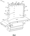
Figure 2 , with continued reference toFigure 1 , aturbine blade 64 is shown by way of example and includes anairfoil 65 extending from aplatform 66. Theairfoil 65 includes apressure side 74 and asuction side 76 that extend from theplatform 66 to atip portion 68 and from a leadingedge 70 to a trailingedge 72. Theexample turbine blade 64 includes coolingopenings 78 that discharge cooling air over external surfaces. - The
tip portion 68 includes apocket portion 80 andshelf portion 82 that are coupled through atransition portion 84. Thepocket portion 80 and theshelf portion 82 include coolingair openings 78. Thepocket portion 80 andshelf portion 82 provide for improved cooling air efficiencies by reducing required cooling airflow. Thepocket portion 80 creates a pocket of cooling air to shield the blade material from heat load due to hot gases. - The
pocket portion 80 is substantially surrounded by thesides transition portion 84 that provides communication with theshelf portion 82. Theshelf portion 82 is open on thepressure side 74 and is a cut away portion that includes an opening. Thetransition portion 84 bridges between thepocket portion 80 andshelf portion 82. - Referring to
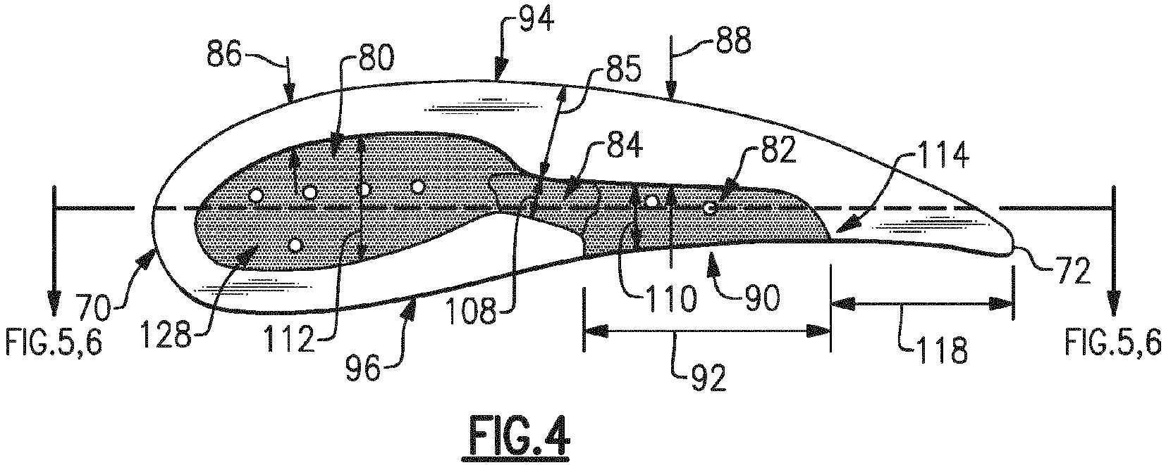
Figures 3 and 4 with continued reference toFigure 2 , thepocket portion 80 is disposed between apressure side wall 96 and asuction side wall 94. Thesuction side wall 94 extends from the leadingedge 70 uninterrupted to the trailingedge 72. It should be appreciated, that thesuction side wall 94 may include cooling openings and still be considered uninterrupted for purposes of this disclosure. Thepressure side wall 96 extends from the leadingedge 70 toward the trailingedge 72 and is interrupted by theshelf portion 82. Theshelf portion 82 defines anopening 90 with awidth 92. Theopening 90 includes an aftmost end 114 that in this disclosed example is spaced from the trailing edge 72 adistance 118. Accordingly, in this disclosed example, theshelf portion 82 does not extend to the trailingedge 72. - The
pocket portion 80, thetransition 84 and theshelf portion 82 may all include a coating schematically shown at 128 to enhance the ability to operate within the extreme temperatures. Moreover, theexample turbine blade 64 is fabricated from known materials utilized within the turbine section of a gas turbine engine and that are compatible with the temperatures and pressures encountered therein. - The
suction side wall 94 varies in width between the leading edge and trailingedge 72. In this disclosed embodiment, thesuction side wall 94 includes awidth 86 within thepocket portion 80 that transitions to awidth 85 within thetransition 84 and subsequently to awidth 88 defined in theshelf portion 82. In this disclosed embodiment, thewidth 88 adjacent theshelf portion 82 is greater than either thewidth 85 or thewidth 86. The increased width of thesuction side wall 96 provides differing features to tailor cooling in view of localized heat loads. - The
transition 84 includes awidth 108 that is less than amaximum width 112 of thepocket portion 80. Thetransition 84 thereby necks down to a reduced width as thesuction side wall 94 increases in width. Thetransition 84 leads into theshelf portion 82 where theshelf portion 84 includes amaximum width 110. In this disclosed embodiment, themaximum width 110 of theshelf portion 82 is less than themaximum width 112 in thepocket portion 80. Thewidth 108 in thetransition 84 is less than either themaximum width 112 ormaximum width 110. - Referring to
Figure 5 , with continued reference toFigure 4 , thepocket portion 80 includes abottom surface 98 disposed at afirst depth 102 from thetop surface 75. The shelf portion includes a bottom surfaces 100 that is spaced at asecond depth 104 from thetop surface 75. Thetransition 84 includes atransition surface 106 that in this disclosed example is sloped upward from thebottom surface 98 in thepocket portion 80 to thebottom surface 104 in theshelf portion 82. Thetransition surface 106 can be sloped as shown inFigure 5 and/or contoured to provide features that encourage cooling air flow between thepocket portion 80 and theshelf portion 82. - Referring to
Figure 6 , with continued reference toFigure 4 , thetransition 84 includes a step 116 between thesurfaces pocket portion 80 and theshelf portion 82 that may be desirable to tailor cooling airflow to accommodate localized heat loads. - Referring to
Figure 7 , with continued reference toFigure 4 , anotherexample tip portion 68 includesdepth 102 in thepocket portion 80 anddepth 104 in theshelf portion 104 that are the same. Thetransition 84 includes asurface 130 that is also at the common depth with thesurfaces surfaces 98 may be flat, contoured or curved and included openings for cooling air. Moreover, other combinations of depths in thepocket portion 80,shelf portion 82 andtransition 84 could be utilized to address location specific heat loads and are within the contemplation of this disclosure. - Referring to
Figure 8 , with continued reference toFigure 4 , the disclosedturbine blade 64 includes acamber line 120 that extends from the leadingedge 70 to the trailingedge 72. Thepocket portion 80 includes alength 122 along thecamber line 120 that is, in this disclosed example greater than alength 126 of theshelf portion 82 along thecamber line 120. Theexample transition 84 includes alength 124 that is smaller than either thelength 122 or thelength 126. It should be appreciated, that thelength 124 may vary depending on application specific requirements. Thepocket portion 80 includes anopen width 112 in a direction transverse to thecamber line 120 that is larger than anopen width 110 of theshelf portion 82 transverse to thecamber line 120. Accordingly, the width of thepocket portion 80 is greater than the width of theshelf portion 82 in this disclosed example embodiment. Thetransition 84 includes awidth 108 transverse to thecamber line 120 that is less than either thewidth 112 or thewidth 110. The reduced width of thetransition 84 provides communication between thepocket portion 80 and theshelf portion 82 while also maintaining cooling airflow as needed to address localized heat loads. - The
example turbine blade 64 can be formed utilizing known fabrication techniques and includes forming theairfoil 65 to include thepressure side 74 and thesuction side 76 extending between theleading edge 70, trailingedge 72, thetip 68 and theplatform 66. Thetip 68 is formed to include thepocket portion 80 and theshelf portion 82 in communication through thetransition 84. Theshelf portion 82 can be cast as part of the original forming process or machined after formation of thepocket portion 80. Machining theshelf portion 82 after formation of theturbine blade 64 enables retrofitting of existing turbine blades to address specific determined localized heat loads. - The
shelf portion 82 is formed aft of thepocket portion 80 such that theshelf portion 82 opens at least partially into thepocket portion 80 through thetransition 84. Thepocket portion 80 and theshelf portion 82 are formed to include the above disclosed variations inwidths widths edge 70 toward the trailingedge 72. Forming thepocket portion 80 includes forming thebottom surface 98 at thefirst depth 102, theshelf portion 82 with thebottom surface 100 at thesecond depth 104 different than thefirst depth 102 and thetransition surface 84 between the first bottom surface and the second bottom surface. Thetransition surface 84 can be formed as cast with thecast shelf portion 82 or alternatively, machined with theshelf portion 82 to retrofit existing blades. - Accordingly, the
example turbine blade 64 includes apocket portion 80 that is in communication with ashelf portion 82 through atransition 84 to enable localized accommodation of specific heat loads to increase operational life. - Although an example embodiment has been disclosed, a worker of ordinary skill in this art would recognize that certain modifications would come within the scope of this disclosure. For that reason, the following claims should be studied to determine the scope and content of this disclosure.
Claims (15)
- A turbine airfoil for a gas turbine engine comprising:a tip portion including a pocket portion that transitions into a shelf portion; anda plurality of cooling holes for communicating cooling airflow to at least one of the pocket portion and the shelf portion.
- The turbine airfoil as recited in claim 1, wherein the tip portion includes an uninterrupted suction side wall with a width that varies from a leading edge toward a trailing edge.
- The turbine airfoil as recited in claim 2, including a transition between the pocket portion and the shelf portion and the width of the suction side wall is greater aft of the transition than forward of the transition.
- The turbine airfoil as recited in claim 2 or 3, wherein the tip portion includes a pressure side wall that extends from the leading edge to the shelf portion.
- The turbine airfoil as recited in any preceding claim, wherein the shelf portion includes an aft end forward of a trailing edge.
- The turbine airfoil as recited in any preceding claim, including a transition between the pocket portion and the shelf portion, the transition including a transition width between a suction side wall and a pressure side wall that is less than at least one of a maximum width of the pocket portion and a maximum width of the shelf portion.
- The turbine airfoil as recited in any preceding claim, including a first bottom surface in the pocket portion and a second bottom surface in the shelf portion and the first bottom surface and the second bottom surfaces are disposed at different depths.
- The turbine airfoil as recited in claim 7, wherein the first bottom surface is at a first depth greater than a second depth of the second bottom surface.
- The turbine airfoil as recited in claim 7 or 8, including a sloped transition surface between the first bottom surface and the second bottom surface, or a step transition between the first bottom surface and the second bottom surface.
- The turbine airfoil as recited in any preceding claim, wherein the pocket portion includes a length along a camber line that is different than a length of the shelf portion along the camber line, and/or wherein the shelf portion includes a width transverse to a camber line that is less than a width of the pocket portion transverse to the camber line.
- The turbine airfoil as recited in any preceding claim, including a coating on surfaces of the pocket portion and the shelf portion.
- A gas turbine engine comprising:
a turbine section including a plurality of turbine blades, wherein at least one of the plurality of turbine blades includes the turbine airfoil as recited in any preceding claim. - A method of making an airfoil for a turbine section of a gas turbine engine, the method comprising:forming an airfoil to include a pressure side and suction side extending between a leading edge, trailing edge a tip and a root;forming the tip to include a pocket portion; andforming a shelf portion aft of the pocket portion, wherein the shelf portion opens at least partially into the pocket portion and a pressure side wall varies in width between the pocket portion and the shelf portion.
- The method as recited in claim 13, including forming a transition portion between the pocket portion and the shelf portion with the transition portion including an open width less than a maximum width of the pocket portion.
- The method as recited in claim 14, including forming the pocket portion with a first bottom surface at a first depth, the shelf portion with a second bottom surface at a second depth different than the first depth and the transition portion with a transition portion between the first bottom surface and the second bottom surface.
Applications Claiming Priority (1)
| Application Number | Priority Date | Filing Date | Title |
|---|---|---|---|
| US15/997,961 US20190368359A1 (en) | 2018-06-05 | 2018-06-05 | Squealer shelf airfoil tip |
Publications (1)
| Publication Number | Publication Date |
|---|---|
| EP3578758A1 true EP3578758A1 (en) | 2019-12-11 |
Family
ID=66770394
Family Applications (1)
| Application Number | Title | Priority Date | Filing Date |
|---|---|---|---|
| EP19178515.3A Withdrawn EP3578758A1 (en) | 2018-06-05 | 2019-06-05 | Turbine airfoil, corresponding gas turbine engine and method of making |
Country Status (2)
| Country | Link |
|---|---|
| US (1) | US20190368359A1 (en) |
| EP (1) | EP3578758A1 (en) |
Families Citing this family (6)
| Publication number | Priority date | Publication date | Assignee | Title |
|---|---|---|---|---|
| DE102018209610A1 (en) * | 2018-06-14 | 2019-12-19 | MTU Aero Engines AG | Blade for a turbomachine |
| USD949794S1 (en) * | 2020-09-04 | 2022-04-26 | Siemens Energy Global GmbH & Co. KG | Turbine blade |
| USD949793S1 (en) * | 2020-09-04 | 2022-04-26 | Siemens Energy Global GmbH & Co. KG | Turbine blade |
| USD946527S1 (en) * | 2020-09-04 | 2022-03-22 | Siemens Energy Global GmbH & Co. KG | Turbine blade |
| EP4001591B1 (en) | 2020-11-13 | 2024-07-24 | Doosan Enerbility Co., Ltd. | Trailing edge tip cooling of blade of a gas turbine blade |
| KR102590947B1 (en) * | 2021-05-04 | 2023-10-19 | 국방과학연구소 | Blade with shelf squealer tip for gas turbine |
Citations (2)
| Publication number | Priority date | Publication date | Assignee | Title |
|---|---|---|---|---|
| EP2351908A1 (en) * | 2008-10-30 | 2011-08-03 | Mitsubishi Heavy Industries, Ltd. | Turbine moving blade having tip thinning |
| EP3301262A1 (en) * | 2016-09-14 | 2018-04-04 | Rolls-Royce plc | Rotor blade |
Family Cites Families (2)
| Publication number | Priority date | Publication date | Assignee | Title |
|---|---|---|---|---|
| GB201406472D0 (en) * | 2014-04-10 | 2014-05-28 | Rolls Royce Plc | Rotor blade |
| US10012089B2 (en) * | 2014-05-16 | 2018-07-03 | United Technologies Corporation | Airfoil tip pocket with augmentation features |
-
2018
- 2018-06-05 US US15/997,961 patent/US20190368359A1/en not_active Abandoned
-
2019
- 2019-06-05 EP EP19178515.3A patent/EP3578758A1/en not_active Withdrawn
Patent Citations (2)
| Publication number | Priority date | Publication date | Assignee | Title |
|---|---|---|---|---|
| EP2351908A1 (en) * | 2008-10-30 | 2011-08-03 | Mitsubishi Heavy Industries, Ltd. | Turbine moving blade having tip thinning |
| EP3301262A1 (en) * | 2016-09-14 | 2018-04-04 | Rolls-Royce plc | Rotor blade |
Also Published As
| Publication number | Publication date |
|---|---|
| US20190368359A1 (en) | 2019-12-05 |
Similar Documents
| Publication | Publication Date | Title |
|---|---|---|
| EP3480430B1 (en) | Integrally bladed rotor for a gas turbine engine and method of fabricating an integrally bladed rotor for a gas turbine engine | |
| EP3578758A1 (en) | Turbine airfoil, corresponding gas turbine engine and method of making | |
| EP2942488B1 (en) | Blade for a gas turbine engine, gas turbine engine and method of cooling a blade for a gas turbine engine | |
| EP2975217A1 (en) | Using inserts to balance heat transfer and stress in high temperature alloys | |
| US10975705B2 (en) | Gas turbine engine airfoil with wishbone baffle cooling scheme | |
| EP3064711B1 (en) | Component for a gas turbine engine, corresponding gas turbine engine and method of forming an airfoil | |
| EP3043027B1 (en) | Gas turbine engine component with conformal fillet cooling path | |
| EP3091184B1 (en) | Turbine airfoil leading edge cooling | |
| EP3090126B1 (en) | Gas turbine engine component comprising endwall countouring trench | |
| EP2993304B1 (en) | Gas turbine engine component with film cooling hole | |
| EP3118414B1 (en) | Gas turbine engine airfoil | |
| EP3094823B1 (en) | Gas turbine engine component and corresponding gas turbine engine | |
| EP2998511B1 (en) | Cooling passage with surface features | |
| EP3078807B2 (en) | Cooling passages for a gas turbine engine component | |
| EP3061910A1 (en) | Gas turbine engine airfoil and corresponding method of forming | |
| EP3255249A1 (en) | Gas turbine engine blade including squealer tip pocket | |
| EP3461993B1 (en) | Gas turbine engine blade | |
| EP3112596A1 (en) | Gas turbine engine airfoil with bi-axial skin cooling passage and corresponding gas turbine engine | |
| EP2993303B1 (en) | Gas turbine engine component with film cooling hole with pocket | |
| US10794194B2 (en) | Staggered core printout | |
| EP3351731A1 (en) | Trailing edge configuration with cast slots and drilled filmholes | |
| EP3054093B1 (en) | Arrangement of trip strips | |
| EP3061913B1 (en) | Gas turbine engine airfoil cooling configuration with pressure gradient separators | |
| EP3477055B1 (en) | Component for a gas turbine engine comprising an airfoil | |
| EP3470627B1 (en) | Gas turbine engine airfoil |
Legal Events
| Date | Code | Title | Description |
|---|---|---|---|
| PUAI | Public reference made under article 153(3) epc to a published international application that has entered the european phase |
Free format text: ORIGINAL CODE: 0009012 |
|
| STAA | Information on the status of an ep patent application or granted ep patent |
Free format text: STATUS: THE APPLICATION HAS BEEN PUBLISHED |
|
| AK | Designated contracting states |
Kind code of ref document: A1 Designated state(s): AL AT BE BG CH CY CZ DE DK EE ES FI FR GB GR HR HU IE IS IT LI LT LU LV MC MK MT NL NO PL PT RO RS SE SI SK SM TR |
|
| AX | Request for extension of the european patent |
Extension state: BA ME |
|
| STAA | Information on the status of an ep patent application or granted ep patent |
Free format text: STATUS: THE APPLICATION HAS BEEN WITHDRAWN |
|
| 18W | Application withdrawn |
Effective date: 20200527 |