EP3578757A2 - Variably skewed trip strips in internally cooled components - Google Patents
Variably skewed trip strips in internally cooled components Download PDFInfo
- Publication number
- EP3578757A2 EP3578757A2 EP19179001.3A EP19179001A EP3578757A2 EP 3578757 A2 EP3578757 A2 EP 3578757A2 EP 19179001 A EP19179001 A EP 19179001A EP 3578757 A2 EP3578757 A2 EP 3578757A2
- Authority
- EP
- European Patent Office
- Prior art keywords
- trip strip
- leg
- cooling channel
- angle
- trip
- Prior art date
- Legal status (The legal status is an assumption and is not a legal conclusion. Google has not performed a legal analysis and makes no representation as to the accuracy of the status listed.)
- Granted
Links
Images


Classifications
-
- F—MECHANICAL ENGINEERING; LIGHTING; HEATING; WEAPONS; BLASTING
- F01—MACHINES OR ENGINES IN GENERAL; ENGINE PLANTS IN GENERAL; STEAM ENGINES
- F01D—NON-POSITIVE DISPLACEMENT MACHINES OR ENGINES, e.g. STEAM TURBINES
- F01D5/00—Blades; Blade-carrying members; Heating, heat-insulating, cooling or antivibration means on the blades or the members
- F01D5/12—Blades
- F01D5/14—Form or construction
- F01D5/18—Hollow blades, i.e. blades with cooling or heating channels or cavities; Heating, heat-insulating or cooling means on blades
- F01D5/187—Convection cooling
-
- F—MECHANICAL ENGINEERING; LIGHTING; HEATING; WEAPONS; BLASTING
- F05—INDEXING SCHEMES RELATING TO ENGINES OR PUMPS IN VARIOUS SUBCLASSES OF CLASSES F01-F04
- F05D—INDEXING SCHEME FOR ASPECTS RELATING TO NON-POSITIVE-DISPLACEMENT MACHINES OR ENGINES, GAS-TURBINES OR JET-PROPULSION PLANTS
- F05D2240/00—Components
- F05D2240/10—Stators
- F05D2240/11—Shroud seal segments
-
- F—MECHANICAL ENGINEERING; LIGHTING; HEATING; WEAPONS; BLASTING
- F05—INDEXING SCHEMES RELATING TO ENGINES OR PUMPS IN VARIOUS SUBCLASSES OF CLASSES F01-F04
- F05D—INDEXING SCHEME FOR ASPECTS RELATING TO NON-POSITIVE-DISPLACEMENT MACHINES OR ENGINES, GAS-TURBINES OR JET-PROPULSION PLANTS
- F05D2250/00—Geometry
- F05D2250/10—Two-dimensional
- F05D2250/11—Two-dimensional triangular
-
- F—MECHANICAL ENGINEERING; LIGHTING; HEATING; WEAPONS; BLASTING
- F05—INDEXING SCHEMES RELATING TO ENGINES OR PUMPS IN VARIOUS SUBCLASSES OF CLASSES F01-F04
- F05D—INDEXING SCHEME FOR ASPECTS RELATING TO NON-POSITIVE-DISPLACEMENT MACHINES OR ENGINES, GAS-TURBINES OR JET-PROPULSION PLANTS
- F05D2250/00—Geometry
- F05D2250/10—Two-dimensional
- F05D2250/18—Two-dimensional patterned
- F05D2250/183—Two-dimensional patterned zigzag
-
- F—MECHANICAL ENGINEERING; LIGHTING; HEATING; WEAPONS; BLASTING
- F05—INDEXING SCHEMES RELATING TO ENGINES OR PUMPS IN VARIOUS SUBCLASSES OF CLASSES F01-F04
- F05D—INDEXING SCHEME FOR ASPECTS RELATING TO NON-POSITIVE-DISPLACEMENT MACHINES OR ENGINES, GAS-TURBINES OR JET-PROPULSION PLANTS
- F05D2250/00—Geometry
- F05D2250/30—Arrangement of components
- F05D2250/31—Arrangement of components according to the direction of their main axis or their axis of rotation
- F05D2250/314—Arrangement of components according to the direction of their main axis or their axis of rotation the axes being inclined in relation to each other
-
- F—MECHANICAL ENGINEERING; LIGHTING; HEATING; WEAPONS; BLASTING
- F05—INDEXING SCHEMES RELATING TO ENGINES OR PUMPS IN VARIOUS SUBCLASSES OF CLASSES F01-F04
- F05D—INDEXING SCHEME FOR ASPECTS RELATING TO NON-POSITIVE-DISPLACEMENT MACHINES OR ENGINES, GAS-TURBINES OR JET-PROPULSION PLANTS
- F05D2250/00—Geometry
- F05D2250/70—Shape
- F05D2250/75—Shape given by its similarity to a letter, e.g. T-shaped
-
- F—MECHANICAL ENGINEERING; LIGHTING; HEATING; WEAPONS; BLASTING
- F05—INDEXING SCHEMES RELATING TO ENGINES OR PUMPS IN VARIOUS SUBCLASSES OF CLASSES F01-F04
- F05D—INDEXING SCHEME FOR ASPECTS RELATING TO NON-POSITIVE-DISPLACEMENT MACHINES OR ENGINES, GAS-TURBINES OR JET-PROPULSION PLANTS
- F05D2260/00—Function
- F05D2260/20—Heat transfer, e.g. cooling
- F05D2260/221—Improvement of heat transfer
- F05D2260/2212—Improvement of heat transfer by creating turbulence
-
- F—MECHANICAL ENGINEERING; LIGHTING; HEATING; WEAPONS; BLASTING
- F05—INDEXING SCHEMES RELATING TO ENGINES OR PUMPS IN VARIOUS SUBCLASSES OF CLASSES F01-F04
- F05D—INDEXING SCHEME FOR ASPECTS RELATING TO NON-POSITIVE-DISPLACEMENT MACHINES OR ENGINES, GAS-TURBINES OR JET-PROPULSION PLANTS
- F05D2260/00—Function
- F05D2260/20—Heat transfer, e.g. cooling
- F05D2260/221—Improvement of heat transfer
- F05D2260/2214—Improvement of heat transfer by increasing the heat transfer surface
- F05D2260/22141—Improvement of heat transfer by increasing the heat transfer surface using fins or ribs
-
- Y—GENERAL TAGGING OF NEW TECHNOLOGICAL DEVELOPMENTS; GENERAL TAGGING OF CROSS-SECTIONAL TECHNOLOGIES SPANNING OVER SEVERAL SECTIONS OF THE IPC; TECHNICAL SUBJECTS COVERED BY FORMER USPC CROSS-REFERENCE ART COLLECTIONS [XRACs] AND DIGESTS
- Y02—TECHNOLOGIES OR APPLICATIONS FOR MITIGATION OR ADAPTATION AGAINST CLIMATE CHANGE
- Y02T—CLIMATE CHANGE MITIGATION TECHNOLOGIES RELATED TO TRANSPORTATION
- Y02T50/00—Aeronautics or air transport
- Y02T50/60—Efficient propulsion technologies, e.g. for aircraft
Definitions
- the present disclosure relates to gas turbine engines, and, more specifically, to an internally cooled component with variably skewed trip strips.
- a gas turbine engine typically includes a fan section, a compressor section, a combustor section, and a turbine section.
- the fan section may drive air along a bypass flowpath while the compressor section may drive air along a core flowpath.
- air is pressurized in the compressor section and is mixed with fuel and burned in the combustor section to generate hot combustion gases.
- the hot combustion gases flow through the turbine section, which extracts energy from the hot combustion gases to power the compressor section and other gas turbine engine loads.
- Turbine airfoils and outer air seals may operate in an environment where the gas temperatures often exceed the thermal capacity of materials in the engine. These parts may incorporate internal cooling channels that utilize cooling air to absorb heat from the part's walls and limit material temperatures.
- a component for a gas turbine engine is disclosed herein.
- the component may comprise an internal cooling channel disposed within the component.
- a first trip strip may extend from a first wall of the internal cooling channel.
- the first trip strip may comprise a first leg extending in a downstream direction toward a second wall of the internal cooling channel.
- the first trip strip may be located a first distance from an inlet of the internal cooling channel.
- the first leg of the first trip strip and a first plane orthogonal to a direction of airflow through the internal cooling channel may form a first angle.
- a second trip strip may extend from the first wall of the internal cooling channel.
- the second trip strip may comprise a first leg extending in the downstream direction toward the second wall of the internal cooling channel.
- the second trip strip may be located a second distance from the inlet.
- the second distance may be greater than the first distance.
- the first leg of the second trip strip and a second plane orthogonal to the direction of airflow through the internal cooling channel may form a second angle different from the first angle.
- the second angle may be less than the first angle.
- the first trip strip and the second trip strip may be chevron-shaped trip strips. An angle formed by the first leg of the first trip strip and a second leg of the first trip strip may be less than an angle formed by the first leg of the second trip strip and a second leg of the second trip strip.
- a third trip strip may be adjacent to the first leg of the first trip strip.
- a fourth trip strip may be adjacent to the first leg of the second trip strip.
- the third trip strip may be approximately parallel to the first leg of the first trip strip.
- the fourth trip strip may be approximately parallel to the first leg of the second trip strip.
- the first trip strip may comprise a W-shaped trip strip.
- a third trip strip may be downstream from the second trip strip and extending from the first wall of the internal cooling channel.
- the third trip strip may comprise a first leg.
- the first leg of the third trip strip and a third plane orthogonal to the direction of airflow through the internal cooling channel may form a third angle.
- the third angle may be approximately equal to the second angle.
- the gas turbine engine may comprise a compressor and an internally cooled component aft of the compressor.
- the internally cooled component may comprise a cooling channel, a first trip strip extending from a first wall of the cooling channel, and a second trip strip downstream from the first trip strip and extending from the first wall of the cooling channel.
- a first leg of the first trip strip may extend in a downstream direction toward a second wall of the cooling channel.
- the first leg of the first trip strip and a first plane orthogonal to a direction of airflow through the cooling channel may form a first angle.
- a first leg of the second trip strip may extend in the downstream direction toward the second wall of the cooling channel.
- the first leg of the second trip strip and a second plane orthogonal to the direction of airflow through the cooling channel may form a second angle different from the first angle.
- the first trip strip may comprise a first chevron-shaped trip strip.
- the internally cooled component may comprise an airfoil.
- the internally cooled component may further comprise a third trip strip adjacent to the first leg of the first trip strip, and a fourth trip strip adjacent to the first leg of the second trip strip.
- the third trip strip may be approximately parallel to the first leg of the first trip strip.
- the fourth trip strip may be approximately parallel to the first leg of the second trip strip.
- the internally cooled component may further comprise a third trip strip downstream from the second trip strip and extending from the first wall of the cooling channel.
- the third trip strip may comprise a first leg.
- the first leg of the third trip strip and a third plane parallel to the first plane and the second plane may form a third angle.
- the third angle may be approximately equal to the second angle.
- the internally cooled component may further comprise a third trip strip extending from a third wall of the cooling channel, and a fourth trip strip downstream from the third trip strip and extending from the third wall of the cooling channel.
- the third wall of the cooling channel may be oriented toward the first wall of the cooling channel.
- an angle formed by the first leg of the first trip strip and a second leg of the first trip strip may be less than an angle formed by the first leg of the second trip strip and a second leg of the second trip strip.
- the airfoil may comprise an internal cooling channel.
- a turbulator may extend from a wall of the internal cooling channel.
- a first portion of the turbulator and a first plane orthogonal to a direction of airflow through the internal cooling channel may form a first angle.
- a second portion of the turbulator, downstream from the first portion, and a second plane orthogonal to the direction of airflow through the internal cooling channel may form a second angle different from the first angle.
- the first portion of the turbulator may comprise a first chevron-shaped trip strip.
- the second portion of the turbulator may comprise a second chevron-shaped trip strip.
- the turbulator may further comprise a third portion downstream from the second portion.
- the third portion and a third plane orthogonal to the direction of airflow through the internal cooling channel may form a third angle approximately equal to the second angle.
- the turbulator may comprise a rifling trip strip formed helically along the internal cooling channel.
- a component for a gas turbine engine may comprise an internal cooling channel disposed within the component.
- a first trip strip may extend from a first wall of the internal cooling channel.
- the first trip strip may comprise a first leg and a second leg joined at a first apex.
- the first leg of the first trip strip and the second leg of the first trip strip may form a first angle.
- a second trip strip may be located downstream of the first trip strip and extending from the first wall of the internal cooling channel.
- the second trip strip may comprise a first leg and a second leg joined at a second apex.
- the first leg of the second trip strip and the second leg of the second trip strip may form a second angle.
- the second angle may be greater than the first angle.
- a third trip strip may be downstream from the second trip strip and extending from the first wall of the internal cooling channel.
- the third trip strip may comprise a first leg and a second leg joined at a third apex.
- the first leg of the third trip strip and the second leg of the third trip strip may form a third angle.
- the third angle may be approximately equal to the second angle.
- the component may comprise an airfoil.
- the first trip strip may comprise a W-shaped trip strip.
- a third trip strip may be adjacent to the first leg of the first trip strip.
- the third trip strip may be approximately parallel to the first leg of the first trip strip.
- a fourth trip strip may be adjacent to the first leg of the second trip strip. The fourth trip strip may be approximately parallel to the first leg of the second trip strip.
- any reference to singular includes plural embodiments, and any reference to more than one component or step may include a singular embodiment or step.
- any reference to attached, fixed, connected or the like may include permanent, removable, temporary, partial, full and/or any other possible attachment option.
- any reference to without contact (or similar phrases) may also include reduced contact or minimal contact. Surface shading lines may be used throughout the figures to denote different parts but not necessarily to denote the same or different materials.
- tail refers to the direction associated with the tail (e.g., the back end) of an aircraft, or generally, to the direction of exhaust of the gas turbine.
- forward refers to the direction associated with the nose (e.g., the front end) of an aircraft, or generally, to the direction of flight or motion.
- distal refers to the direction outward, or generally, away from a reference component.
- proximate refers to a direction inward, or generally, towards the reference component.
- a first component that is "radially outward" of a second component means that the first component is positioned at a greater distance away from the engine central longitudinal axis than the second component.
- a first component that is “radially inward” of a second component means that the first component is positioned closer to the engine central longitudinal axis than the second component.
- a first component that is radially inward of a second component rotates through a circumferentially shorter path than the second component.
- the terminology “radially outward” and “radially inward” may also be used relative to references other than the engine central longitudinal axis.
- Gas turbine engine 20 may be a two-spool turbofan that generally incorporates a fan section 22, a compressor section 24, a combustor section 26, and a turbine section 28.
- fan section 22 can drive fluid (e.g., air) along a bypass flow-path B while compressor section 24 can drive fluid along a core flow-path C for compression and communication into combustor section 26 and then expansion through turbine section 28.
- fluid e.g., air
- compressor section 24 can drive fluid along a core flow-path C for compression and communication into combustor section 26 and then expansion through turbine section 28.
- Gas turbine engine 20 may generally comprise a low speed spool 30 and a high speed spool 32 mounted for rotation about an engine central longitudinal axis A-A' relative to an engine static structure 36 via several bearing systems 38, 38-1, and 38-2. It should be understood that various bearing systems 38 at various locations may alternatively or additionally be provided, including for example, bearing system 38, bearing system 38-1, and bearing system 38-2.
- Low speed spool 30 may generally comprise an inner shaft 40 that interconnects a fan 42, a low-pressure compressor 44 and a low-pressure turbine 46.
- Inner shaft 40 may be connected to fan 42 through a geared architecture 48 that can drive fan 42 at a lower speed than low speed spool 30.
- Geared architecture 48 may comprise a gear assembly 60 enclosed within a gear housing 62.
- Gear assembly 60 couples inner shaft 40 to a rotating fan structure.
- High speed spool 32 may comprise an outer shaft 50 that interconnects a high-pressure compressor 52 and high-pressure turbine 54. Airfoils 100 of high-pressure turbine 54 may rotate about the engine central longitudinal axis A-A'.
- a combustor 56 may be located between high-pressure compressor 52 and high-pressure turbine 54.
- a mid-turbine frame 57 may support one or more bearing systems 38 in turbine section 28.
- Inner shaft 40 and outer shaft 50 may be concentric and rotate via bearing systems 38 about the engine central longitudinal axis A-A', which is collinear with their longitudinal axes.
- a "high-pressure" compressor or turbine experiences a higher pressure than a corresponding "low-pressure” compressor or turbine.
- the core airflow C may be compressed by low-pressure compressor 44 then high-pressure compressor 52, mixed and burned with fuel in combustor 56, then expanded over high-pressure turbine 54 and low-pressure turbine 46.
- Turbines 46, 54 rotationally drive the respective low speed spool 30 and high speed spool 32 in response to the expansion.
- Gas turbine engine 20 may include one or more internally cooled component.
- airfoils 100 in high pressure turbine 54 may comprise internally cooled engine components.
- Trip strips may be located in internal cavities of internally cooled engine components, as detailed further below.
- Internally cooled engine components may be discussed in the present disclosure in terms of airfoils. However, the present disclosure applies to any internally cooled engine component (e.g., blade outer air seals, airfoil platforms, combustor liners, blades, vanes, or any other internally cooled component in a gas turbine engine).
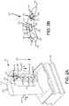
- FIG. 2A illustrates an airfoil 100 having variably skewed trip strips 108 located in an internal cavity 110 (also referred to herein as cooling channel 110) of airfoil 100, in accordance with various embodiments.
- Airfoil 100 may include a hub 102 for attaching airfoil 100 to a disk of a rotor system.
- Airfoil 100 comprises a radially outer edge or tip 103 located radially outward from hub 102.
- Airfoil 100 has a leading edge 104 and a trailing edge 106 opposite leading edge 104.
- Airfoil 100 may include a generally concave pressure side 109 and a generally convex suction side 113 joined together at the respective leading edge 104 and trailing edge 106.
- a portion of pressure side 109 is cutaway to illustrate trip strips 108 formed on a wall 112 of cooling channel 110.
- a material 107 of airfoil 100 may define internal channels, such as cooling channel 110, of airfoil 100.
- Trip strips 108 may protrude and extend from wall 112 of cooling channel 110.
- a fluid such as coolant 116 e.g., air
- Trip strips 108 formed along the wall(s) of cooling channel 110 may "trip" the flow of coolant 116, thereby increasing local flow velocity and turbulence, which in turn, may increase heat transfer capacity.
- trip strips 108 form a turbulator 111 within cooling channel 110.
- coolant 116 may be illustrated as flowing through cooling channel 110 in a radially inward direction, the present disclosure applies to coolant flowing in any direction (e.g., radially outward, forward, aft, etc.). Stated differently, the present disclosure applies to cooling channels oriented in any direction.
- airfoil 100 may include a radially oriented cooling channel with an inlet proximate to hub 102 so that coolant flows in a generally radially outward direction.
- airfoil 100 may include an axially oriented cooling channel with an inlet located proximate leading edge 104 so that coolant 116 flows in a direction generally from leading edge 104 toward trailing edge 106.
- airfoil 100 may include an axially oriented cooling channel with an inlet located proximate trailing edge 106 so that coolant 116 flows in a direction generally from trailing edge 106 toward leading edge 104.
- an angle of the legs of trip strips 108 may vary through cooling channel 110 such that the legs of the trip strips 108 closer to an inlet of cooling channel 110 (i.e., closer to tip 103) may be oriented at an angle, relative to the direction of airflow through cooling channel 110, that is different from the legs of the trip strips 108 distal to the inlet of cooling channel 110 (i.e., closer to hub 102).
- Airfoil 100 may contain multiple cooling channels similar to cooling channel 110, as further illustrated in FIG. 2B .
- the internal cooling channels are interconnected.
- trip strips 108 may be formed on multiple walls of the internal cooling channel.
- Cooling channel 110 includes trip strips 108 on two walls.
- a first set of trip strips 108 may extend from wall 112 and a second set of trip strips 108 may extend from a second wall, which is oriented generally towards wall 112.
- a cooling channel 115 has trip strips 108 disposed about four walls of cooling channel 115.
- a cooling channel 117 includes trip strips 108 on one wall.
- Trip strips 108 may be disposed on any wall of a cooling channel.
- any number of trip strips may be deployed as a turbulator for airflow through a cooling channel and providing increased surface area for heat transfer.
- trip strips 108 tend to increase heat transfer between coolant (i.e., air from the compressor section) and the walls of internal cooling channels. Thus, cooling efficiency may be improved.
- trip strips 108 may be made using an additive manufacturing technique such as direct metal laser sintering, selective laser sintering, selective laser melting, electron-beam melting, or electron-beam freeform fabrication. Casting may also be used to form trip strips 108 in an internally cooled component.
- Airfoil 100 (as well as other internally cooled components) may be made from an austenitic nickel-chromium-based alloy such as that sold under the trademark Inconel® which is available from Special Metals Corporation of New Hartford, New York, USA, or other materials capable of withstanding exhaust temperatures.
- FIGs. 3A-3F illustrate trip strip configurations that may be formed on one or more walls of an internally cooled component, in accordance various embodiments.
- wall 112 of cooling channel 110 having chevron-shaped trip strips 108a, 108b, 108c, 108d, 108e is illustrated, in accordance with various embodiments.
- Chevron-shaped trip strips 108a, 108b, 108c, 108d, 108e may each include a first leg 120 and a second leg 122 joined at an apex 124.
- the apex 124 of each chevron-shaped trip strip 108a, 108b, 108c, 108d, 108e is oriented toward an inlet 130 of cooling channel 110.
- First leg 120 may extend from apex 124 toward a wall 126 of cooling channeling 110, in a forward downstream direction.
- Second leg 122 may extend from apex 124 toward a wall 127 of cooling channeling 110, in an aftward downstream direction.
- Wall 126 may be oriented generally toward wall 127.
- Coolant 116 flows generally from inlet 130 toward an outlet 132 of cooling channel 110 (i.e., in the direction of arrow 136), such that chevron-shaped trip strip 108b is downstream from chevron-shaped trip strip 108a, chevron-shaped trip strip 108c is downstream from chevron-shaped trip strip 108b, chevron-shaped trip strip 108d is downstream from chevron-shaped trip strip 108c, etc.
- Chevron-shaped trip strips 108a, 108b, 108c, 108d, 108e may form turbulator 111.
- a first portion of turbulator 111 may include a first trip strip (e.g., chevron-shaped trip strip 108a) and a second portion of turbulator 111 may include a second trip strip downstream of the first trip strip (e.g. chevron-shaped trip strip 108b, 108c, 108d, or 108e).
- first trip strip e.g., chevron-shaped trip strip 108a
- second portion of turbulator 111 may include a second trip strip downstream of the first trip strip (e.g. chevron-shaped trip strip 108b, 108c, 108d, or 108e).
- An angle theta ( ⁇ ) may be formed by first leg 120 and second leg 122.
- An angle alpha ( ⁇ ) may be formed by first leg 120 and an imaginary plane 134.
- Plane 134 is generally orthogonal to a direction (illustrated by arrow 136) of airflow (e.g., coolant 116) through cooling channel 110. Stated differently, plane 134 is generally orthogonal to a direction extending from inlet 130 toward outlet 132 of cooling channel 110. Stated yet another way, plane 134 is generally orthogonal to wall 112 of cooling channel 110. As used in the present context only, "generally orthogonal" means between 85° and 95°.
- An angle beta ( ⁇ ) maybe formed by second leg 122 and plane 134.
- chevron-shaped trip strips 108a, 108b, 108c, 108d, 108e may be variably skewed such that angles ⁇ and ⁇ vary relative to the trip strip's distance from inlet 130.
- angle ⁇ a of chevron-shaped trip strip 108a may be greater than angle ⁇ b of chevron-shaped trip strip 108b.
- Angle ⁇ a of chevron-shaped trip strip 108a may be greater than angle ⁇ b of chevron-shaped trip strip 108b.
- Angles ⁇ b and ⁇ b of chevron-shaped trip strip 108b may be greater, respectively, than angles ⁇ c and ⁇ c of chevron-shaped trip strip 108c.
- Angles ⁇ c and ⁇ c of chevron-shaped trip strip 108c may be greater, respectively, than angles ⁇ d and ⁇ d of chevron-shaped trip strip 108d.
- angles ⁇ d and ⁇ d of chevron-shaped trip strip 108d may be approximately equal, respectively, to angles ⁇ e and ⁇ e of chevron-shaped trip strip 108e
- any chevron-shaped trips strips downstream of chevron-shaped trip strip 108e may comprise angles ⁇ and ⁇ that are approximately equal, respectively, to angles ⁇ e and ⁇ e of chevron-shaped trip strip 108e.
- “approximately equal” means ⁇ 2°.
- chevron-shaped trip strips 108d and 108e may be configured having angles ⁇ and ⁇ that generate an optimal or a particular amount of swirl based on a particular Reynolds number of coolant 116.
- angles ⁇ e and ⁇ e of chevron-shaped trip strip 108e may each be between 20° and 60°.
- angles ⁇ e and ⁇ e of chevron-shaped trip strip 108e may each be between 30° and 50°.
- angles ⁇ e and ⁇ e of chevron-shaped trip strip 108e may each be approximately 45°.
- "approximately" means ⁇ 2°.
- turbulator 111 may be illustrated as achieving optimal or full swirl by the fourth and fifth trip strips (e.g., by chevron-shaped trip strips 108d and 108e), the present disclosure applies to turbulators wherein an optimal or a full swirl is achieved downstream of the fourth and fifth trip strips, for example, at the seventh trip strip downstream from inlet 130, or at the tenth trip strip, or the twentieth trip strip. In this regard, angles ⁇ and ⁇ may continue to change at and beyond the fourth and fifth trip strips.
- angles ⁇ d and ⁇ d of chevron-shaped trip strip 108d may be greater, respectively, than angles ⁇ e and ⁇ e of chevron-shaped trip strip 108e, and angles ⁇ e and ⁇ e of chevron-shaped trip strip 108e may be greater, respectively, than the angles ⁇ and ⁇ of one or more chevron-shaped trip strips downstream from chevron-shaped trip strip 108e.
- chevron-shaped trip strips with greater angles ⁇ and ⁇ proximate to inlet 130 of cooling channel 110 tends to catalyze a swirling flow of coolant 116.
- locating chevron-shaped trip strips with the greatest angles ⁇ and ⁇ proximate inlet 130 and decreasing angles ⁇ and ⁇ in subsequent downstream chevron-shaped trip strips tends to decrease the distance required to develop a swirling flow of coolant 116.
- chevron-shaped trip strips 108a, 108b, 108c, 108d, 108e may be variably skewed such that angle ⁇ varies relative to the trip strip's distance from inlet 130.
- angle ⁇ a of chevron-shaped trip strip 108a may be less than angle ⁇ b of chevron-shaped trip strip 108b.
- Angle ⁇ b of chevron-shaped trip strip 108b may be less than angle ⁇ c of chevron-shaped trip strip 108c.
- Angle ⁇ c of chevron-shaped trip strip 108c may be less than angle ⁇ d of chevron-shaped trip strip 108d.
- angle ⁇ d of chevron-shaped trip strip 108d may be approximately equal to angle ⁇ e of chevron-shaped trip strip 108e, and any chevron-shaped trips strips downstream of chevron-shaped trip strip 108e may comprise an angle ⁇ that is approximately equal to angles ⁇ d and ⁇ e of chevron-shaped trip strips 108d and 108e.
- “approximately equal” means ⁇ 2°.
- chevron-shaped trip strips 108d and 108e may be configured having an angle ⁇ that generates an optimal or a particular amount of swirl based on a particular Reynolds number of coolant 116.
- angle ⁇ e of chevron-shaped trip strip 108e may be between 60° and 140°. In various embodiments, angle ⁇ e of chevron-shaped trip strip 108e may be between 80° and 120°. In various embodiments, angle ⁇ e of chevron-shaped trip strip 108e may be approximately 90°. As used in the present context only, “approximately” means ⁇ 2°.
- FIG. 3B illustrates a wall of a cooling channel with turbulator 111 including additional trip strips adjacent to chevron-shaped trip strips, in accordance with various embodiments.
- one or more trip strip(s) may be formed adjacent to the chevron-shaped trip strips located proximate inlet 130 of cooling channel 110.
- chevron-shaped trip strip 108a may be supplemented with a trip strip 146a adjacent to first leg 120, and with a trip strip 148a adjacent to second leg 122.
- Chevron-shaped trip strip 108b may be supplemented with a trip strip 146b adjacent to first leg 120, and with a trip strip 148b adjacent to second leg 122.
- trip strips 146a, 146b, 148a, and 148b may be linear, or rectangular-shaped, trip strips.
- Trip strip 146a and plane 134a form an angle gamma (ya).
- Trip strip 148a and plane 134a form an angle delta ( ⁇ a).
- Trip strip 146b and plane 134b form an angle ⁇ b.
- Trip strip 148b and plane 134b form an angle ⁇ b.
- angle ⁇ a may be greater than angle yb, and angle ⁇ a may be greater than angle ⁇ b.
- angle ⁇ a may be equal to angle ⁇ a of chevron-shaped trip strip 108a, and angle ⁇ a may be equal to angle ⁇ a.
- trip strip 146a may be approximately parallel to first leg 120 of chevron-shaped trip strip 108a
- trip strip 148a may be approximately parallel to second leg 122 of chevron-shaped trip strip 108a.
- trip strips 146b and 148b may be approximately parallel, respectively, to first leg 120 and second leg 122 of chevron-shaped trip strip 108b.
- approximately equal means ⁇ 2°.
- angles ⁇ a and ⁇ a may differ, respectively, from angles ⁇ a and ⁇ a of chevron-shaped trip strip 108a (i.e., angles ⁇ a and ⁇ a may be greater than or less than angles ⁇ a and ⁇ a) and angles ⁇ b and ⁇ b may differ, respectively, from angles ⁇ b and ⁇ b of chevron-shaped trip strip 108b.
- Trip strips 158a, 158b, 158c, 158d, 158e each comprise a single leg 159.
- trip strips 158a, 158b, 158c, 158d, 158e may be linear, or rectangular-shaped, trip strips.
- Each leg 159 is oriented at an angle epsilon ( ⁇ ) relative to plane 134. In other words, each leg 159 and its respective plane 134 form angle ⁇ .
- Trip strips 158a, 158b, 158c, 158d, 158e may be variably skewed such that angle ⁇ varies relative to the trip strip's distance from inlet 130.
- angle ⁇ a of trip strip 158a may be greater than angle ⁇ b of trip strip 158b.
- Angle ⁇ b of trip strip 158b may be greater than angle ⁇ c of trip strip 158c.
- Angle ⁇ c of trip strip 158c may be greater than angle ⁇ d of trip strip 158d.
- angle ⁇ d of trip strip 158d may be approximately equal to angle ⁇ e of trip strip 158e, and any trips strips downstream of trip strip 158e may comprise an angle ⁇ that is approximately equal to angle ⁇ e of trip strips 158d and 158e.
- “approximately equal” means ⁇ 2°.
- trip strips 158d and 158e may be oriented at an angle ⁇ that generates an optimal or a particular amount of swirl based on a particular Reynolds number of coolant 116.
- W-shaped trip strips 168a, 168b, 168c, 168d, 168e may each include a leg 170 and a leg 172 joined at an apex 173.
- Apex 173 may be oriented toward inlet 130 of cooling channel 110.
- Leg 170 may extend from apex 173 in a forward downstream direction toward wall 126 of cooling channeling 110.
- Leg 172 may extend from apex 173 in an aftward downstream direction toward wall 127 of cooling channeling 110.
- W-shaped trip strips 168a, 168b, 168c, 168d, 168e may each further include a leg 174 joined to leg 172 at an apex 175.
- Apex 175 may be oriented toward outlet 132 of cooling channel 110.
- Leg 172 may extend from apex 175 in a forward upstream direction toward wall 126 of cooling channeling 110.
- Leg 174 may extend from apex 175 in an aftward upstream direction toward wall 127 of cooling channeling 110.
- W-shaped trip strips 168a, 168b, 168c, 168d, 168e may each further include a leg 176 joined to leg 174 at an apex 177.
- Apex 177 may be oriented toward inlet 130 of cooling channel 110.
- Leg 174 may extend from apex 177 in a forward downstream direction toward wall 126 of cooling channeling 110.
- Leg 176 may extend from apex 177 in an aftward downstream direction toward wall
- Leg 170 of each W-shaped trip strip 168a, 168b, 168c, 168d, 168e may be oriented at an angle kappa ( ⁇ ) relative to plane 134.
- Leg 176 of each W-shaped trip strip 168a, 168b, 168c, 168d, 168e may be oriented at an angle lambda ( ⁇ ) relative to plane 134.
- Legs 170 and 172 of each W-shaped trip strip 168a, 168b, 168c, 168d, 168e may form an angle mu1 ( ⁇ 1).
- Legs 172 and 174 of each W-shaped trip strip 168a, 168b, 168c, 168d, 168e may form an angle ⁇ 2.
- Legs 174 and 176 of each W-shaped trip strip 168a, 168b, 168c, 168d, 168e may form an angle ⁇ 3.
- W-shaped trip strips 168a, 168b, 168c, 168d, 168e may be variably skewed such that angles ⁇ and ⁇ vary relative to the trip strip's distance from inlet 130.
- angles ⁇ and ⁇ may decrease in subsequent downstream W-shaped trip strips.
- angles ⁇ a and ⁇ a of W-shaped trip strip 168a may be greater, respectively, than angles ⁇ b and ⁇ b of W-shaped trip strip 168b.
- Angles ⁇ b and ⁇ b of W-shaped trip strip 168b may be greater, respectively, than angles ⁇ c and ⁇ c of W-shaped trip strip 168c.
- Angles ⁇ c and ⁇ c of W-shaped trip strip 168c may be greater, respectively, than angles ⁇ d and ⁇ d of W-shaped trip strip 168d.
- angles ⁇ d and ⁇ d of W-shaped trip strip 168d may be approximately equal to angles ⁇ e and ⁇ c of W-shaped trip strip 168e, and any trips strips downstream of W-shaped trip strip 168e may comprise angles ⁇ and ⁇ that are approximately equal angles ⁇ e and ⁇ e of W-shaped trip strip 168e.
- “approximately equal” means ⁇ 2°.
- W-shaped trip strips 168d and 168e maybe oriented at angles ⁇ and ⁇ that generate an optimal or a particular amount of swirl based on a particular Reynolds number of coolant 116.
- angles ⁇ 1, ⁇ 2, and/or ⁇ 3 may vary relative to the W-shaped trip strip's distance from inlet 130. In this regard, angles ⁇ 1, ⁇ 2, and/or ⁇ 3 may increase in subsequent downstream W-shaped trip strips. For example, angle ⁇ 1, ⁇ 2, and/or ⁇ 3 of W-shaped trip strip 168a may be greater, respectively, than angle ⁇ 1, ⁇ 2, and/or ⁇ 3 of W-shaped trip strip 168b. Angle ⁇ 1, ⁇ 2, and/or ⁇ 3 of W-shaped trip strip 168b may be greater, respectively, than angle ⁇ 1, ⁇ 2, and/or ⁇ 3 of W-shaped trip strip 168c.
- Angle ⁇ 1, ⁇ 2, and/or ⁇ 3 of W-shaped trip strip 168c may be greater, respectively, than angle ⁇ 1, ⁇ 2, and/or ⁇ 3 of W-shaped trip strip 168d, and angle ⁇ 1, ⁇ 2, and/or ⁇ 3 of W-shaped trip strip 168d may be approximately equal, respectively, to angle ⁇ 1, ⁇ 2, and/or ⁇ 3 of W-shaped trip strip 168e.
- Any trips strips downstream of W-shaped trip strip 168e may comprise angles ⁇ 1, ⁇ 2, and/or ⁇ 3 that are approximately equal angles ⁇ 1, ⁇ 2, and/or ⁇ 3 of W-shaped trip strip 168e.
- “approximately equal” means ⁇ 2°.
- W-shaped trip strips 168d and 168e may be oriented at angles ⁇ 1, ⁇ 2, and ⁇ 3 that generate an optimal or a particular amount of swirl based on a particular Reynolds number of coolant 116.
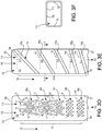
- FIG. 3E a wall of cooling channel 110 with turbulator 111 having a rifling trip strip 178 is shown, in accordance with various embodiments.
- FIG. 3F shows a cross sectional view of cooling channel 110 along line F-F in FIG. 3E .
- Rifling trip strip 178 may be formed helically along the walls of cooling channel 110.
- rifling trip strip 178 may include a plurality of variably skewed portions, for example, portions 178a, 178b, 178c, 178d, 178e.
- Portions 178a, 178b, 178c, 178d, 178e may each be oriented at an angle sigma ( ⁇ ) relative to plane 134.
- Angle ⁇ may vary relative to the distance from inlet 130. In this regard, angle ⁇ may decrease in subsequent downstream portions of rifling trip strip 178.
- angle ⁇ a of portion 178a may be greater than angle ⁇ b of portion 178b.
- Angle ⁇ b of portion 178b may be greater than angle ⁇ c of portion 178c.
- Angle ⁇ c of portion 178c may be greater than angle ⁇ d of portion 178d.
- angle ⁇ d of portion 178d may be approximately equal to angle ⁇ e of portion 178e, and any remaining downstream portions of rifling trip strip 178 may remain oriented at an angle ⁇ that is approximately equal to the angle ⁇ e formed by portion 178e and plane 134.
- “approximately equal” means ⁇ 2°.
- portions 178d and 178e may be oriented at an angle ⁇ that generates an optimal or a particular amount of swirl based on a particular Reynolds number of coolant 116.
- trip strips having legs oriented at greater angles, relative to a plane (e.g., plane 134) orthogonal to the direction of airflow through the cooling channel, near the inlet of the cooling channel tends to catalyze a swirling of coolant flowing through the channel.
- a plane e.g., plane 134
- locating trip strips with legs oriented at the greatest angles, relative to plane 134, proximate to the inlet and decreasing the angles of the legs, relative to plane 134, in subsequent downstream trip strips tends to decrease the distance required to develop a swirling flow of coolant.
- Variably skewed trip strips may reduce pressure and flow velocity losses associated with tripping the coolant flow at the inlet of the cooling channel.
- the increased angles of the legs proximate the inlet may cause a gradual turning of the coolant flow entering the cooling channel. This gradual turning, may reduce turbulent losses and low velocity separation regions downstream of the trip strips.
- Turning the coolant flow near the inlet may also allow the swirling flow structure to develop sooner, rather than delaying the onset of swirls by turbulating the flow. A greater presence of swirling flow within a cooling channel may lead to greater mixing and therefore greater heat exchange capacity.
- references to "various embodiments”, “one embodiment”, “an embodiment”, “an example embodiment”, etc. indicate that the embodiment described may include a particular feature, structure, or characteristic, but every embodiment may not necessarily include the particular feature, structure, or characteristic. Moreover, such phrases are not necessarily referring to the same embodiment. Further, when a particular feature, structure, or characteristic is described in connection with an embodiment, it is submitted that it is within the knowledge of one skilled in the art to affect such feature, structure, or characteristic in connection with other embodiments whether or not explicitly described. After reading the description, it will be apparent to one skilled in the relevant art(s) how to implement the disclosure in alternative embodiments.
Landscapes
- Engineering & Computer Science (AREA)
- Mechanical Engineering (AREA)
- General Engineering & Computer Science (AREA)
- Turbine Rotor Nozzle Sealing (AREA)
Abstract
Description
- The present disclosure relates to gas turbine engines, and, more specifically, to an internally cooled component with variably skewed trip strips.
- A gas turbine engine typically includes a fan section, a compressor section, a combustor section, and a turbine section. The fan section may drive air along a bypass flowpath while the compressor section may drive air along a core flowpath. In general, during operation, air is pressurized in the compressor section and is mixed with fuel and burned in the combustor section to generate hot combustion gases. The hot combustion gases flow through the turbine section, which extracts energy from the hot combustion gases to power the compressor section and other gas turbine engine loads.
- Turbine airfoils and outer air seals may operate in an environment where the gas temperatures often exceed the thermal capacity of materials in the engine. These parts may incorporate internal cooling channels that utilize cooling air to absorb heat from the part's walls and limit material temperatures.
- A component for a gas turbine engine is disclosed herein. In accordance with various embodiments, the component may comprise an internal cooling channel disposed within the component. A first trip strip may extend from a first wall of the internal cooling channel. The first trip strip may comprise a first leg extending in a downstream direction toward a second wall of the internal cooling channel. The first trip strip may be located a first distance from an inlet of the internal cooling channel. The first leg of the first trip strip and a first plane orthogonal to a direction of airflow through the internal cooling channel may form a first angle. A second trip strip may extend from the first wall of the internal cooling channel. The second trip strip may comprise a first leg extending in the downstream direction toward the second wall of the internal cooling channel. The second trip strip may be located a second distance from the inlet. The second distance may be greater than the first distance. The first leg of the second trip strip and a second plane orthogonal to the direction of airflow through the internal cooling channel may form a second angle different from the first angle.
- In various embodiments, the second angle may be less than the first angle. In various embodiments, the first trip strip and the second trip strip may be chevron-shaped trip strips. An angle formed by the first leg of the first trip strip and a second leg of the first trip strip may be less than an angle formed by the first leg of the second trip strip and a second leg of the second trip strip.
- In various embodiments, a third trip strip may be adjacent to the first leg of the first trip strip. A fourth trip strip may be adjacent to the first leg of the second trip strip. The third trip strip may be approximately parallel to the first leg of the first trip strip. The fourth trip strip may be approximately parallel to the first leg of the second trip strip.
- In various embodiments, the first trip strip may comprise a W-shaped trip strip. In various embodiments, a third trip strip may be downstream from the second trip strip and extending from the first wall of the internal cooling channel. The third trip strip may comprise a first leg. The first leg of the third trip strip and a third plane orthogonal to the direction of airflow through the internal cooling channel may form a third angle. The third angle may be approximately equal to the second angle.
- A gas turbine engine is also disclosed herein. In accordance with various embodiments, the gas turbine engine may comprise a compressor and an internally cooled component aft of the compressor. The internally cooled component may comprise a cooling channel, a first trip strip extending from a first wall of the cooling channel, and a second trip strip downstream from the first trip strip and extending from the first wall of the cooling channel. A first leg of the first trip strip may extend in a downstream direction toward a second wall of the cooling channel. The first leg of the first trip strip and a first plane orthogonal to a direction of airflow through the cooling channel may form a first angle. A first leg of the second trip strip may extend in the downstream direction toward the second wall of the cooling channel. The first leg of the second trip strip and a second plane orthogonal to the direction of airflow through the cooling channel may form a second angle different from the first angle.
- In various embodiments, the first trip strip may comprise a first chevron-shaped trip strip. In various embodiments, the internally cooled component may comprise an airfoil.
- In various embodiments, the internally cooled component may further comprise a third trip strip adjacent to the first leg of the first trip strip, and a fourth trip strip adjacent to the first leg of the second trip strip. The third trip strip may be approximately parallel to the first leg of the first trip strip. The fourth trip strip may be approximately parallel to the first leg of the second trip strip.
- In various embodiments, the internally cooled component may further comprise a third trip strip downstream from the second trip strip and extending from the first wall of the cooling channel. The third trip strip may comprise a first leg. The first leg of the third trip strip and a third plane parallel to the first plane and the second plane may form a third angle. The third angle may be approximately equal to the second angle.
- In various embodiments, the internally cooled component may further comprise a third trip strip extending from a third wall of the cooling channel, and a fourth trip strip downstream from the third trip strip and extending from the third wall of the cooling channel. The third wall of the cooling channel may be oriented toward the first wall of the cooling channel.
- In various embodiments, an angle formed by the first leg of the first trip strip and a second leg of the first trip strip may be less than an angle formed by the first leg of the second trip strip and a second leg of the second trip strip.
- An airfoil is also disclosed herein. In accordance with various embodiments, the airfoil may comprise an internal cooling channel. A turbulator may extend from a wall of the internal cooling channel. A first portion of the turbulator and a first plane orthogonal to a direction of airflow through the internal cooling channel may form a first angle. A second portion of the turbulator, downstream from the first portion, and a second plane orthogonal to the direction of airflow through the internal cooling channel may form a second angle different from the first angle.
- In various embodiments, the first portion of the turbulator may comprise a first chevron-shaped trip strip. The second portion of the turbulator may comprise a second chevron-shaped trip strip.
- In various embodiments, the turbulator may further comprise a third portion downstream from the second portion. The third portion and a third plane orthogonal to the direction of airflow through the internal cooling channel may form a third angle approximately equal to the second angle.
- In various embodiments, the turbulator may comprise a rifling trip strip formed helically along the internal cooling channel.
- In various embodiments, a component for a gas turbine engine may comprise an internal cooling channel disposed within the component. A first trip strip may extend from a first wall of the internal cooling channel. The first trip strip may comprise a first leg and a second leg joined at a first apex. The first leg of the first trip strip and the second leg of the first trip strip may form a first angle. A second trip strip may be located downstream of the first trip strip and extending from the first wall of the internal cooling channel. The second trip strip may comprise a first leg and a second leg joined at a second apex. The first leg of the second trip strip and the second leg of the second trip strip may form a second angle. The second angle may be greater than the first angle.
- In various embodiments, a third trip strip may be downstream from the second trip strip and extending from the first wall of the internal cooling channel. The third trip strip may comprise a first leg and a second leg joined at a third apex. The first leg of the third trip strip and the second leg of the third trip strip may form a third angle. The third angle may be approximately equal to the second angle.
- In various embodiments, the component may comprise an airfoil. In various embodiments, the first trip strip may comprise a W-shaped trip strip.
- In various embodiments, a third trip strip may be adjacent to the first leg of the first trip strip. The third trip strip may be approximately parallel to the first leg of the first trip strip. A fourth trip strip may be adjacent to the first leg of the second trip strip. The fourth trip strip may be approximately parallel to the first leg of the second trip strip.
- The foregoing features and elements may be combined in various combinations without exclusivity, unless expressly indicated otherwise. These features and elements as well as the operation thereof will become more apparent in light of the following description and the accompanying drawings. It should be understood, however, the following description and drawings are intended to be exemplary in nature and non-limiting.
- The subject matter of the present disclosure is particularly pointed out and distinctly claimed in the concluding portion of the specification. A more complete understanding of the present disclosure, however, may best be obtained by referring to the detailed description and claims when considered in connection with the figures, wherein like numerals denote like elements.
-
FIG. 1 illustrates an exemplary gas turbine engine, in accordance with various embodiments; -
FIG. 2A illustrates a perspective view of an airfoil having a cooling channel with variably skewed trip strips, in accordance with various embodiments; -
FIG. 2B illustrates a cross-sectional view of the airfoil ofFIG. 2A take along the line D-D inFIG. 2A , in accordance with various embodiments; -
FIG. 3A illustrates a wall of a cooling channel having variably skewed chevron-shaped trip strips, in accordance with various embodiments; -
FIG. 3B illustrates a wall of a cooling channel having a combination of variably skewed chevron-shaped and linear trip strips, in accordance with various embodiments; -
FIG. 3C illustrates a wall of a cooling channel having variably skewed trip strips, in accordance with various embodiments; -
FIG. 3D illustrates a wall of a cooling channel having variably skewed W-shaped trip strips, in accordance with various embodiments; -
FIG. 3E illustrates a wall of a cooling channel having a variably skewed trip strip in a riffling geometry, in accordance with various embodiments; and -
FIG. 3F illustrates a cross-sectional view of the cooling channel ofFIG. 3E take along the line F-F inFIG. 3E , in accordance with various embodiments. - The detailed description of exemplary embodiments herein makes reference to the accompanying drawings, which show exemplary embodiments by way of illustration. While these exemplary embodiments are described in sufficient detail to enable those skilled in the art to practice the exemplary embodiments of the disclosure, it should be understood that other embodiments may be realized and that logical changes and adaptations in design and construction may be made in accordance with this disclosure and the teachings herein. Thus, the detailed description herein is presented for purposes of illustration only and not limitation. The scope of the disclosure is defined by the appended claims. For example, the steps recited in any of the method or process descriptions may be executed in any order and are not necessarily limited to the order presented.
- Furthermore, any reference to singular includes plural embodiments, and any reference to more than one component or step may include a singular embodiment or step. Also, any reference to attached, fixed, connected or the like may include permanent, removable, temporary, partial, full and/or any other possible attachment option. Additionally, any reference to without contact (or similar phrases) may also include reduced contact or minimal contact. Surface shading lines may be used throughout the figures to denote different parts but not necessarily to denote the same or different materials.
- As used herein, "aft" refers to the direction associated with the tail (e.g., the back end) of an aircraft, or generally, to the direction of exhaust of the gas turbine. As used herein, "forward" refers to the direction associated with the nose (e.g., the front end) of an aircraft, or generally, to the direction of flight or motion.
- As used herein, "distal" refers to the direction outward, or generally, away from a reference component. As used herein, "proximate" refers to a direction inward, or generally, towards the reference component.
- A first component that is "radially outward" of a second component means that the first component is positioned at a greater distance away from the engine central longitudinal axis than the second component. A first component that is "radially inward" of a second component means that the first component is positioned closer to the engine central longitudinal axis than the second component. In the case of components that rotate circumferentially about the engine central longitudinal axis, a first component that is radially inward of a second component rotates through a circumferentially shorter path than the second component. The terminology "radially outward" and "radially inward" may also be used relative to references other than the engine central longitudinal axis.
- In various embodiments and with reference to
FIG. 1 , a gas turbine engine 20 is provided. Gas turbine engine 20 may be a two-spool turbofan that generally incorporates a fan section 22, a compressor section 24, a combustor section 26, and aturbine section 28. In operation, fan section 22 can drive fluid (e.g., air) along a bypass flow-path B while compressor section 24 can drive fluid along a core flow-path C for compression and communication into combustor section 26 and then expansion throughturbine section 28. Although depicted as a turbofan gas turbine engine 20 herein, it should be understood that the concepts described herein are not limited to use with turbofans as the teachings may be applied to other types of turbine engines including multi-spool architectures. - Gas turbine engine 20 may generally comprise a low speed spool 30 and a high speed spool 32 mounted for rotation about an engine central longitudinal axis A-A' relative to an engine static structure 36 via several bearing systems 38, 38-1, and 38-2. It should be understood that various bearing systems 38 at various locations may alternatively or additionally be provided, including for example, bearing system 38, bearing system 38-1, and bearing system 38-2.
- Low speed spool 30 may generally comprise an
inner shaft 40 that interconnects afan 42, a low-pressure compressor 44 and a low-pressure turbine 46.Inner shaft 40 may be connected to fan 42 through a geared architecture 48 that can drivefan 42 at a lower speed than low speed spool 30. Geared architecture 48 may comprise a gear assembly 60 enclosed within a gear housing 62. Gear assembly 60 couplesinner shaft 40 to a rotating fan structure. High speed spool 32 may comprise an outer shaft 50 that interconnects a high-pressure compressor 52 and high-pressure turbine 54.Airfoils 100 of high-pressure turbine 54 may rotate about the engine central longitudinal axis A-A'. - A combustor 56 may be located between high-pressure compressor 52 and high-pressure turbine 54. A mid-turbine frame 57 may support one or more bearing systems 38 in
turbine section 28.Inner shaft 40 and outer shaft 50 may be concentric and rotate via bearing systems 38 about the engine central longitudinal axis A-A', which is collinear with their longitudinal axes. As used herein, a "high-pressure" compressor or turbine experiences a higher pressure than a corresponding "low-pressure" compressor or turbine. - The core airflow C may be compressed by low-pressure compressor 44 then high-pressure compressor 52, mixed and burned with fuel in combustor 56, then expanded over high-pressure turbine 54 and low-pressure turbine 46. Turbines 46, 54 rotationally drive the respective low speed spool 30 and high speed spool 32 in response to the expansion.
- Gas turbine engine 20 may include one or more internally cooled component. For example,
airfoils 100 in high pressure turbine 54 may comprise internally cooled engine components. Trip strips may be located in internal cavities of internally cooled engine components, as detailed further below. Internally cooled engine components may be discussed in the present disclosure in terms of airfoils. However, the present disclosure applies to any internally cooled engine component (e.g., blade outer air seals, airfoil platforms, combustor liners, blades, vanes, or any other internally cooled component in a gas turbine engine). -
FIG. 2A illustrates anairfoil 100 having variably skewed trip strips 108 located in an internal cavity 110 (also referred to herein as cooling channel 110) ofairfoil 100, in accordance with various embodiments.Airfoil 100 may include ahub 102 for attachingairfoil 100 to a disk of a rotor system.Airfoil 100 comprises a radially outer edge or tip 103 located radially outward fromhub 102.Airfoil 100 has aleading edge 104 and a trailingedge 106 oppositeleading edge 104.Airfoil 100 may include a generallyconcave pressure side 109 and a generallyconvex suction side 113 joined together at the respectiveleading edge 104 and trailingedge 106. - A portion of
pressure side 109 is cutaway to illustrate trip strips 108 formed on awall 112 of coolingchannel 110. Amaterial 107 ofairfoil 100 may define internal channels, such ascooling channel 110, ofairfoil 100. Trip strips 108 may protrude and extend fromwall 112 of coolingchannel 110. A fluid such as coolant 116 (e.g., air) may be directed throughcooling channel 110 generally in a direction (illustrated by arrow 136) fromtip 103 towards hub 102 (i.e., in a radially inward direction) whenairfoil 100 is installed in a turbine. Trip strips 108 formed along the wall(s) ofcooling channel 110 may "trip" the flow ofcoolant 116, thereby increasing local flow velocity and turbulence, which in turn, may increase heat transfer capacity. In this regard, trip strips 108 form aturbulator 111 within coolingchannel 110. Whilecoolant 116 may be illustrated as flowing throughcooling channel 110 in a radially inward direction, the present disclosure applies to coolant flowing in any direction (e.g., radially outward, forward, aft, etc.). Stated differently, the present disclosure applies to cooling channels oriented in any direction. For example, in various embodiments,airfoil 100 may include a radially oriented cooling channel with an inlet proximate tohub 102 so that coolant flows in a generally radially outward direction. In various embodiments,airfoil 100 may include an axially oriented cooling channel with an inlet located proximateleading edge 104 so thatcoolant 116 flows in a direction generally from leadingedge 104 toward trailingedge 106. In various embodiments,airfoil 100 may include an axially oriented cooling channel with an inlet locatedproximate trailing edge 106 so thatcoolant 116 flows in a direction generally from trailingedge 106 toward leadingedge 104. - As described in further detail below, an angle of the legs of trip strips 108 may vary through
cooling channel 110 such that the legs of the trip strips 108 closer to an inlet of cooling channel 110 (i.e., closer to tip 103) may be oriented at an angle, relative to the direction of airflow throughcooling channel 110, that is different from the legs of the trip strips 108 distal to the inlet of cooling channel 110 (i.e., closer to hub 102). -
Airfoil 100 may contain multiple cooling channels similar to coolingchannel 110, as further illustrated inFIG. 2B . In various embodiments, the internal cooling channels are interconnected. In various embodiments, trip strips 108 may be formed on multiple walls of the internal cooling channel. - With further reference to
FIG. 2B , a cross sectional view along line D-D inFIG. 2A is shown, in accordance with various embodiments.Cooling channel 110 includes trip strips 108 on two walls. In this regard, a first set of trip strips 108 may extend fromwall 112 and a second set of trip strips 108 may extend from a second wall, which is oriented generally towardswall 112. A coolingchannel 115 has trip strips 108 disposed about four walls of coolingchannel 115. A coolingchannel 117 includes trip strips 108 on one wall. Trip strips 108 may be disposed on any wall of a cooling channel. Similarly, any number of trip strips may be deployed as a turbulator for airflow through a cooling channel and providing increased surface area for heat transfer. In that regard, trip strips 108 tend to increase heat transfer between coolant (i.e., air from the compressor section) and the walls of internal cooling channels. Thus, cooling efficiency may be improved. - In various embodiments, trip strips 108 may be made using an additive manufacturing technique such as direct metal laser sintering, selective laser sintering, selective laser melting, electron-beam melting, or electron-beam freeform fabrication. Casting may also be used to form trip strips 108 in an internally cooled component. Airfoil 100 (as well as other internally cooled components) may be made from an austenitic nickel-chromium-based alloy such as that sold under the trademark Inconel® which is available from Special Metals Corporation of New Hartford, New York, USA, or other materials capable of withstanding exhaust temperatures.
-
FIGs. 3A-3F illustrate trip strip configurations that may be formed on one or more walls of an internally cooled component, in accordance various embodiments. With reference toFIG. 3A ,wall 112 of coolingchannel 110 having chevron-shapedtrip strips trip strips first leg 120 and asecond leg 122 joined at an apex 124. The apex 124 of each chevron-shapedtrip strip inlet 130 of coolingchannel 110.First leg 120 may extend fromapex 124 toward awall 126 of cooling channeling 110, in a forward downstream direction.Second leg 122 may extend fromapex 124 toward awall 127 of cooling channeling 110, in an aftward downstream direction.Wall 126 may be oriented generally towardwall 127. -
Coolant 116 flows generally frominlet 130 toward anoutlet 132 of cooling channel 110 (i.e., in the direction of arrow 136), such that chevron-shapedtrip strip 108b is downstream from chevron-shapedtrip strip 108a, chevron-shapedtrip strip 108c is downstream from chevron-shapedtrip strip 108b, chevron-shapedtrip strip 108d is downstream from chevron-shapedtrip strip 108c, etc. Chevron-shapedtrip strips turbulator 111. Stated differently, a first portion ofturbulator 111 may include a first trip strip (e.g., chevron-shapedtrip strip 108a) and a second portion ofturbulator 111 may include a second trip strip downstream of the first trip strip (e.g. chevron-shapedtrip strip - An angle theta (θ) may be formed by
first leg 120 andsecond leg 122. An angle alpha (α) may be formed byfirst leg 120 and animaginary plane 134.Plane 134 is generally orthogonal to a direction (illustrated by arrow 136) of airflow (e.g., coolant 116) throughcooling channel 110. Stated differently,plane 134 is generally orthogonal to a direction extending frominlet 130 towardoutlet 132 of coolingchannel 110. Stated yet another way,plane 134 is generally orthogonal to wall 112 of coolingchannel 110. As used in the present context only, "generally orthogonal" means between 85° and 95°. An angle beta (β) maybe formed bysecond leg 122 andplane 134. - In various embodiments, chevron-shaped
trip strips inlet 130. For example, angle αa of chevron-shapedtrip strip 108a may be greater than angle αb of chevron-shapedtrip strip 108b. Angle βa of chevron-shapedtrip strip 108a may be greater than angle βb of chevron-shapedtrip strip 108b. Angles αb and βb of chevron-shapedtrip strip 108b may be greater, respectively, than angles αc and βc of chevron-shapedtrip strip 108c. Angles αc and βc of chevron-shapedtrip strip 108c may be greater, respectively, than angles αd and βd of chevron-shapedtrip strip 108d. In various embodiments, angles αd and βd of chevron-shapedtrip strip 108d may be approximately equal, respectively, to angles αe and βe of chevron-shapedtrip strip 108e, and any chevron-shaped trips strips downstream of chevron-shapedtrip strip 108e may comprise angles α and β that are approximately equal, respectively, to angles αe and βe of chevron-shapedtrip strip 108e. As used in the present context only, "approximately equal" means ±2°. In this regard, chevron-shaped trip strips 108d and 108e may be configured having angles α and β that generate an optimal or a particular amount of swirl based on a particular Reynolds number ofcoolant 116. In various embodiments, angles αe and βe of chevron-shapedtrip strip 108e may each be between 20° and 60°. In various embodiments, angles αe and βe of chevron-shapedtrip strip 108e may each be between 30° and 50°. In various embodiments, angles αe and βe of chevron-shapedtrip strip 108e may each be approximately 45°. As used in the present context only, "approximately" means ±2°. - While
turbulator 111 may be illustrated as achieving optimal or full swirl by the fourth and fifth trip strips (e.g., by chevron-shaped trip strips 108d and 108e), the present disclosure applies to turbulators wherein an optimal or a full swirl is achieved downstream of the fourth and fifth trip strips, for example, at the seventh trip strip downstream frominlet 130, or at the tenth trip strip, or the twentieth trip strip. In this regard, angles α and β may continue to change at and beyond the fourth and fifth trip strips. For example, in various embodiments, angles αd and βd of chevron-shapedtrip strip 108d may be greater, respectively, than angles αe and βe of chevron-shapedtrip strip 108e, and angles αe and βe of chevron-shapedtrip strip 108e may be greater, respectively, than the angles α and β of one or more chevron-shaped trip strips downstream from chevron-shapedtrip strip 108e. - Utilizing chevron-shaped trip strips with greater angles α and β proximate to
inlet 130 of coolingchannel 110 tends to catalyze a swirling flow ofcoolant 116. In this regard, locating chevron-shaped trip strips with the greatest angles α and βproximate inlet 130 and decreasing angles α and β in subsequent downstream chevron-shaped trip strips tends to decrease the distance required to develop a swirling flow ofcoolant 116. - In various embodiments, chevron-shaped
trip strips inlet 130. For example, angle θa of chevron-shapedtrip strip 108a may be less than angle θb of chevron-shapedtrip strip 108b. Angle θb of chevron-shapedtrip strip 108b may be less than angle θc of chevron-shapedtrip strip 108c. Angle θc of chevron-shapedtrip strip 108c may be less than angle θd of chevron-shapedtrip strip 108d. In various embodiments, angle θd of chevron-shapedtrip strip 108d may be approximately equal to angle θe of chevron-shapedtrip strip 108e, and any chevron-shaped trips strips downstream of chevron-shapedtrip strip 108e may comprise an angle θ that is approximately equal to angles θd and θe of chevron-shaped trip strips 108d and 108e. As used in the present context only, "approximately equal" means ±2°. In this regard, chevron-shaped trip strips 108d and 108e may be configured having an angle θ that generates an optimal or a particular amount of swirl based on a particular Reynolds number ofcoolant 116. In various embodiments, angle θe of chevron-shapedtrip strip 108e may be between 60° and 140°. In various embodiments, angle θe of chevron-shapedtrip strip 108e may be between 80° and 120°. In various embodiments, angle θe of chevron-shapedtrip strip 108e may be approximately 90°. As used in the present context only, "approximately" means ±2°. -
FIG. 3B illustrates a wall of a cooling channel withturbulator 111 including additional trip strips adjacent to chevron-shaped trip strips, in accordance with various embodiments. In various embodiments, one or more trip strip(s) may be formed adjacent to the chevron-shaped trip strips locatedproximate inlet 130 of coolingchannel 110. For example, chevron-shapedtrip strip 108a may be supplemented with atrip strip 146a adjacent tofirst leg 120, and with atrip strip 148a adjacent tosecond leg 122. Chevron-shapedtrip strip 108b may be supplemented with atrip strip 146b adjacent tofirst leg 120, and with atrip strip 148b adjacent tosecond leg 122. In various embodiments,trip strips -
Trip strip 146a andplane 134a form an angle gamma (ya).Trip strip 148a andplane 134a form an angle delta (δa).Trip strip 146b andplane 134b form an angle γb.Trip strip 148b andplane 134b form an angle δb. In various embodiments, angle γa may be greater than angle yb, and angle δa may be greater than angle δb. In various embodiments, angle γa may be equal to angle αa of chevron-shapedtrip strip 108a, and angle δa may be equal to angle βa. Stated differently,trip strip 146a may be approximately parallel tofirst leg 120 of chevron-shapedtrip strip 108a, andtrip strip 148a may be approximately parallel tosecond leg 122 of chevron-shapedtrip strip 108a. In various embodiments, trip strips 146b and 148b may be approximately parallel, respectively, tofirst leg 120 andsecond leg 122 of chevron-shapedtrip strip 108b. As used in the present context only, "approximately equal" means ±2°. In various embodiments, angles γa and δa may differ, respectively, from angles αa and βa of chevron-shapedtrip strip 108a (i.e., angles γa and δa may be greater than or less than angles αa and βa) and angles γb and δb may differ, respectively, from angles αb and βb of chevron-shapedtrip strip 108b. - With reference to
FIG. 3C , a wall of coolingchannel 110 withturbulator 111 having variably skewedtrip strips Trip strips single leg 159. In various embodiments,trip strips leg 159 is oriented at an angle epsilon (ε) relative to plane 134. In other words, eachleg 159 and itsrespective plane 134 form angle ε.Trip strips inlet 130. For example, angle εa oftrip strip 158a may be greater than angle εb oftrip strip 158b. Angle εb oftrip strip 158b may be greater than angle εc oftrip strip 158c. Angle εc oftrip strip 158c may be greater than angle εd oftrip strip 158d. In various embodiments, angle εd oftrip strip 158d may be approximately equal to angle εe oftrip strip 158e, and any trips strips downstream oftrip strip 158e may comprise an angle ε that is approximately equal to angle εe oftrip strips coolant 116. - With reference to
FIG. 3D , a wall of coolingchannel 110 withturbulator 111 having variably skewed W-shapedtrip strips trip strips leg 170 and aleg 172 joined at an apex 173.Apex 173 may be oriented towardinlet 130 of coolingchannel 110.Leg 170 may extend fromapex 173 in a forward downstream direction towardwall 126 of cooling channeling 110.Leg 172 may extend fromapex 173 in an aftward downstream direction towardwall 127 of cooling channeling 110. W-shapedtrip strips leg 172 at an apex 175.Apex 175 may be oriented towardoutlet 132 of coolingchannel 110.Leg 172 may extend fromapex 175 in a forward upstream direction towardwall 126 of cooling channeling 110. Leg 174 may extend fromapex 175 in an aftward upstream direction towardwall 127 of cooling channeling 110. W-shapedtrip strips leg 176 joined to leg 174 at an apex 177.Apex 177 may be oriented towardinlet 130 of coolingchannel 110. Leg 174 may extend fromapex 177 in a forward downstream direction towardwall 126 of cooling channeling 110.Leg 176 may extend fromapex 177 in an aftward downstream direction towardwall 127 of cooling channeling 110. -
Leg 170 of each W-shapedtrip strip Leg 176 of each W-shapedtrip strip Legs trip strip Legs 172 and 174 of each W-shapedtrip strip Legs 174 and 176 of each W-shapedtrip strip - W-shaped
trip strips inlet 130. In this regard, angles κ and λ may decrease in subsequent downstream W-shaped trip strips. For example, angles κa and λa of W-shapedtrip strip 168a may be greater, respectively, than angles κb and λb of W-shapedtrip strip 168b. Angles κb and λb of W-shapedtrip strip 168b may be greater, respectively, than angles κc and λc of W-shapedtrip strip 168c. Angles κc and λc of W-shapedtrip strip 168c may be greater, respectively, than angles κd and λd of W-shapedtrip strip 168d. In various embodiments, angles κd and λd of W-shapedtrip strip 168d may be approximately equal to angles κe and λc of W-shapedtrip strip 168e, and any trips strips downstream of W-shapedtrip strip 168e may comprise angles κ and λ that are approximately equal angles κe and λe of W-shapedtrip strip 168e. As used in the present context only, "approximately equal" means ±2°. In this regard, W-shaped trip strips 168d and 168e maybe oriented at angles κ and λ that generate an optimal or a particular amount of swirl based on a particular Reynolds number ofcoolant 116. - In various embodiments, angles µ1, µ2, and/or µ3 may vary relative to the W-shaped trip strip's distance from
inlet 130. In this regard, angles µ1, µ2, and/or µ3 may increase in subsequent downstream W-shaped trip strips. For example, angle µ1, µ2, and/or µ3 of W-shapedtrip strip 168a may be greater, respectively, than angle µ1, µ2, and/or µ3 of W-shapedtrip strip 168b. Angle µ1, µ2, and/or µ3 of W-shapedtrip strip 168b may be greater, respectively, than angle µ1, µ2, and/or µ3 of W-shapedtrip strip 168c. Angle µ1, µ2, and/or µ3 of W-shapedtrip strip 168c may be greater, respectively, than angle µ1, µ2, and/or µ3 of W-shapedtrip strip 168d, and angle µ1, µ2, and/or µ3 of W-shapedtrip strip 168d may be approximately equal, respectively, to angle µ1, µ2, and/or µ3 of W-shapedtrip strip 168e. Any trips strips downstream of W-shapedtrip strip 168e may comprise angles µ1, µ2, and/or µ3 that are approximately equal angles µ1, µ2, and/or µ3 of W-shapedtrip strip 168e. As used in the present context only, "approximately equal" means ±2°. In this regard, W-shaped trip strips 168d and 168e may be oriented at angles µ1, µ2, and µ3 that generate an optimal or a particular amount of swirl based on a particular Reynolds number ofcoolant 116. - With reference to
FIGs. 3E , a wall of coolingchannel 110 withturbulator 111 having arifling trip strip 178 is shown, in accordance with various embodiments.FIG. 3F shows a cross sectional view ofcooling channel 110 along line F-F inFIG. 3E . With combined reference toFIGs. 3E and 3F .Rifling trip strip 178 may be formed helically along the walls of coolingchannel 110. In various embodiments, riflingtrip strip 178 may include a plurality of variably skewed portions, for example,portions Portions inlet 130. In this regard, angle σ may decrease in subsequent downstream portions of riflingtrip strip 178. For example, angle σa ofportion 178a may be greater than angle σb ofportion 178b. Angle σb ofportion 178b may be greater than angle σc ofportion 178c. Angle σc ofportion 178c may be greater than angle σd ofportion 178d. In various embodiments, angle σd ofportion 178d may be approximately equal to angle σe ofportion 178e, and any remaining downstream portions of riflingtrip strip 178 may remain oriented at an angle σ that is approximately equal to the angle σe formed byportion 178e andplane 134. As used in the present context only, "approximately equal" means ±2°. In this regard,portions coolant 116. - Utilizing trip strips having legs oriented at greater angles, relative to a plane (e.g., plane 134) orthogonal to the direction of airflow through the cooling channel, near the inlet of the cooling channel tends to catalyze a swirling of coolant flowing through the channel. In this regard, locating trip strips with legs oriented at the greatest angles, relative to
plane 134, proximate to the inlet and decreasing the angles of the legs, relative toplane 134, in subsequent downstream trip strips tends to decrease the distance required to develop a swirling flow of coolant. Variably skewed trip strips (i.e., trip strips having legs oriented at varying angles relative to the direction of airflow through the channel) may reduce pressure and flow velocity losses associated with tripping the coolant flow at the inlet of the cooling channel. The increased angles of the legs proximate the inlet may cause a gradual turning of the coolant flow entering the cooling channel. This gradual turning, may reduce turbulent losses and low velocity separation regions downstream of the trip strips. Turning the coolant flow near the inlet may also allow the swirling flow structure to develop sooner, rather than delaying the onset of swirls by turbulating the flow. A greater presence of swirling flow within a cooling channel may lead to greater mixing and therefore greater heat exchange capacity. - Benefits and other advantages have been described herein with regard to specific embodiments. Furthermore, the connecting lines shown in the various figures contained herein are intended to represent exemplary functional relationships and/or physical couplings between the various elements. It should be noted that many alternative or additional functional relationships or physical connections may be present in a practical system. However, the benefits, advantages, and any elements that may cause any benefit or advantage to occur or become more pronounced are not to be construed as critical, required, or essential features or elements of the disclosure. The scope of the disclosure is accordingly to be limited by nothing other than the appended claims, in which reference to an element in the singular is not intended to mean "one and only one" unless explicitly so stated, but rather "one or more." Moreover, where a phrase similar to "at least one of A, B, or C" is used in the claims, it is intended that the phrase be interpreted to mean that A alone may be present in an embodiment, B alone may be present in an embodiment, C alone may be present in an embodiment, or that any combination of the elements A, B and C may be present in a single embodiment; for example, A and B, A and C, B and C, or A and B and C.
- Systems, methods and apparatus are provided herein. In the detailed description herein, references to "various embodiments", "one embodiment", "an embodiment", "an example embodiment", etc., indicate that the embodiment described may include a particular feature, structure, or characteristic, but every embodiment may not necessarily include the particular feature, structure, or characteristic. Moreover, such phrases are not necessarily referring to the same embodiment. Further, when a particular feature, structure, or characteristic is described in connection with an embodiment, it is submitted that it is within the knowledge of one skilled in the art to affect such feature, structure, or characteristic in connection with other embodiments whether or not explicitly described. After reading the description, it will be apparent to one skilled in the relevant art(s) how to implement the disclosure in alternative embodiments.
- Furthermore, no element, component, or method step in the present disclosure is intended to be dedicated to the public regardless of whether the element, component, or method step is explicitly recited in the claims. No claim element is intended to invoke 35 U.S.C. 112(f) unless the element is expressly recited using the phrase "means for." As used herein, the terms "comprises", "comprising", or any other variation thereof, are intended to cover a non-exclusive inclusion, such that a process, method, article, or apparatus that comprises a list of elements does not include only those elements but may include other elements not expressly listed or inherent to such process, method, article, or apparatus.
Claims (15)
- A component for a gas turbine engine, comprising:an internal cooling channel disposed within the component;a first trip strip extending from a first wall of the internal cooling channel, the first trip strip comprising a first leg extending in a downstream direction toward a second wall of the internal cooling channel, wherein the first trip strip is located a first distance from an inlet of the internal cooling channel, and wherein the first leg of the first trip strip and a first plane orthogonal to a direction of airflow through the internal cooling channel form a first angle; anda second trip strip extending from the first wall of the internal cooling channel, the second trip strip comprising a first leg extending in the downstream direction toward the second wall of the internal cooling channel, wherein the second trip strip is located a second distance from the inlet, the second distance being greater than the first distance, and wherein the first leg of the second trip strip and a second plane orthogonal to the direction of airflow through the internal cooling channel form a second angle different from the first angle.
- The component of claim 1, wherein the second angle is less than the first angle.
- The component of claim 1 or 2, wherein the first trip strip and the second trip strip are chevron-shaped trip strips.
- The component of claim 1, 2 or 3, further comprising a third trip strip downstream from the second trip strip and extending from the first wall of the internal cooling channel, the third trip strip comprising a first leg, wherein the first leg of the third trip strip and a third plane orthogonal to the direction of airflow through the internal cooling channel form a third angle, and wherein the third angle is approximately equal to the second angle.
- A gas turbine engine, comprising:a compressor; andan internally cooled component aft of the compressor, the internally cooled component comprising:a cooling channel,a first trip strip extending from a first wall of the cooling channel, wherein a first leg of the first trip strip extends in a downstream direction toward a second wall of the cooling channel, and wherein the first leg of the first trip strip and a first plane generally orthogonal to a direction of airflow through the cooling channel form a first angle, anda second trip strip downstream from the first trip strip and extending from the first wall of the cooling channel, wherein a first leg of the second trip strip extends in the downstream direction toward the second wall of the cooling channel, and wherein the first leg of the second trip strip and a second plane orthogonal to the direction of airflow through the cooling channel form a second angle different from the first angle.
- The gas turbine engine of claim 5, wherein the first trip strip comprises a chevron-shaped trip.
- The gas turbine engine of claim 5 or 6, wherein the internally cooled component further comprises a third trip strip downstream from the second trip strip and extending from the first wall of the cooling channel, the third trip strip comprising a first leg, wherein the first leg of the third trip strip and a third plane parallel to the first plane and the second plane form a third angle, and wherein the third angle is approximately equal to the second angle, or
wherein the internally cooled component further comprises:a third trip strip extending from a third wall of the cooling channel, wherein the third wall of the cooling channel is oriented toward the first wall of the cooling channel; anda fourth trip strip downstream from the third trip strip and extending from the third wall of the cooling channel. - The component of claim 3 or 4 or the gas turbine engine of any of claims 5 to 7, wherein an angle formed by the first leg of the first trip strip and a second leg of the first trip strip is less than an angle formed by the first leg of the second trip strip and a second leg of the second trip strip.
- An airfoil, comprising:an internal cooling channel; anda turbulator formed in the internal cooling channel, wherein a first portion of the turbulator and a first plane orthogonal to a direction of airflow through the internal cooling channel form a first angle, and wherein a second portion of the turbulator downstream from the first portion and a second plane orthogonal to the direction of airflow through the internal cooling channel form a second angle different from the first angle.
- The airfoil of claim 9, wherein the first portion of the turbulator comprises a first chevron-shaped trip strip, and wherein the second portion of the turbulator comprises a second chevron-shaped trip strip.
- The airfoil of claim 9 or 10, wherein the turbulator further comprises a third portion downstream from the second portion, and wherein the third portion and a third orthogonal to the direction of airflow through the internal cooling channel form a third angle approximately equal to the second angle, wherein, optionally, the turbulator comprises a rifling trip strip formed helically along the internal cooling channel.
- A component for a gas turbine engine, comprising:an internal cooling channel disposed within the component;a first trip strip extending from a first wall of the internal cooling channel, the first trip strip comprising a first leg and a second leg joined at a first apex, wherein the first leg of the first trip strip and the second leg of the first trip strip form a first angle; anda second trip strip located downstream of the first trip strip and extending from the first wall of the internal cooling channel, the second trip strip comprising a first leg and a second leg joined at a second apex, wherein the first leg of the second trip strip and the second leg of the second trip strip form a second angle, and wherein the second angle is greater than the first angle, optionally further comprising a third trip strip downstream from the second trip strip and extending from the first wall of the internal cooling channel, the third trip strip comprising a first leg and a second leg joined at a third apex, wherein the first leg of the third trip strip and the second leg of the third trip strip form a third angle, and wherein the third angle is approximately equal to the second angle.
- The gas turbine engine of any of claims 5 to 8 or the component of claim 12, wherein the internally cooled component or the component comprises an airfoil.
- The component of claim 1 or 21, wherein the first trip strip comprises a W-shaped trip strip.
- The component of claim 3 or 12 or the gas turbine engine of claim 5, the internally cooled component or the component further comprising:a third trip strip adjacent to the first leg of the first trip strip; anda fourth trip strip adjacent to the first leg of the second trip strip,wherein, optionally, the third trip strip is approximately parallel to the first leg of the first trip strip, and wherein the fourth trip strip is approximately parallel to the first leg of the second trip strip.
Applications Claiming Priority (1)
| Application Number | Priority Date | Filing Date | Title |
|---|---|---|---|
| US16/002,313 US11085304B2 (en) | 2018-06-07 | 2018-06-07 | Variably skewed trip strips in internally cooled components |
Publications (3)
| Publication Number | Publication Date |
|---|---|
| EP3578757A2 true EP3578757A2 (en) | 2019-12-11 |
| EP3578757A3 EP3578757A3 (en) | 2020-03-18 |
| EP3578757B1 EP3578757B1 (en) | 2023-04-05 |
Family
ID=66793831
Family Applications (1)
| Application Number | Title | Priority Date | Filing Date |
|---|---|---|---|
| EP19179001.3A Active EP3578757B1 (en) | 2018-06-07 | 2019-06-07 | Variably skewed trip strips in internally cooled components |
Country Status (2)
| Country | Link |
|---|---|
| US (1) | US11085304B2 (en) |
| EP (1) | EP3578757B1 (en) |
Families Citing this family (3)
| Publication number | Priority date | Publication date | Assignee | Title |
|---|---|---|---|---|
| US10808552B2 (en) * | 2018-06-18 | 2020-10-20 | Raytheon Technologies Corporation | Trip strip configuration for gaspath component in a gas turbine engine |
| JP7847031B2 (en) * | 2022-05-06 | 2026-04-16 | 三菱重工業株式会社 | Turbine blades and gas turbines |
| US12286898B2 (en) | 2023-04-18 | 2025-04-29 | Rtx Corporation | Layout for asymmetric cast trips in long passages |
Family Cites Families (12)
| Publication number | Priority date | Publication date | Assignee | Title |
|---|---|---|---|---|
| JP4489336B2 (en) | 1999-06-28 | 2010-06-23 | シーメンス アクチエンゲゼルシヤフト | Structural parts that receive hot gases |
| US7866947B2 (en) | 2007-01-03 | 2011-01-11 | United Technologies Corporation | Turbine blade trip strip orientation |
| US7955053B1 (en) | 2007-09-21 | 2011-06-07 | Florida Turbine Technologies, Inc. | Turbine blade with serpentine cooling circuit |
| WO2014112968A1 (en) | 2013-01-15 | 2014-07-24 | United Technologies Corporation | Gas turbine engine component having transversely angled impingement ribs |
| EP2954168B1 (en) * | 2013-02-05 | 2019-07-03 | United Technologies Corporation | Gas turbine engine component having curved turbulator |
| WO2014159800A1 (en) | 2013-03-14 | 2014-10-02 | United Technologies Corporation | Obtuse angle chevron trip strip |
| US9039371B2 (en) * | 2013-10-31 | 2015-05-26 | Siemens Aktiengesellschaft | Trailing edge cooling using angled impingement on surface enhanced with cast chevron arrangements |
| EP2944762B1 (en) | 2014-05-12 | 2016-12-21 | General Electric Technology GmbH | Airfoil with improved cooling |
| CA2950011C (en) * | 2014-05-29 | 2020-01-28 | General Electric Company | Fastback turbulator |
| US10156157B2 (en) | 2015-02-13 | 2018-12-18 | United Technologies Corporation | S-shaped trip strips in internally cooled components |
| US10202864B2 (en) | 2016-02-09 | 2019-02-12 | United Technologies Corporation | Chevron trip strip |
| US10590778B2 (en) * | 2017-08-03 | 2020-03-17 | General Electric Company | Engine component with non-uniform chevron pins |
-
2018
- 2018-06-07 US US16/002,313 patent/US11085304B2/en active Active
-
2019
- 2019-06-07 EP EP19179001.3A patent/EP3578757B1/en active Active
Also Published As
| Publication number | Publication date |
|---|---|
| US20190376393A1 (en) | 2019-12-12 |
| EP3578757B1 (en) | 2023-04-05 |
| US11085304B2 (en) | 2021-08-10 |
| EP3578757A3 (en) | 2020-03-18 |
Similar Documents
| Publication | Publication Date | Title |
|---|---|---|
| US10436038B2 (en) | Turbine engine with an airfoil having a tip shelf outlet | |
| US10808546B2 (en) | Gas turbine engine airfoil trailing edge suction side cooling | |
| JP6255051B2 (en) | Method for positioning adjacent nozzles of a gas turbine engine | |
| US7334985B2 (en) | Shroud with aero-effective cooling | |
| EP3088670A1 (en) | Film cooled component and corresponding film cooling system | |
| EP3309362B1 (en) | Stator vane rail | |
| EP3043028B1 (en) | Mini blind stator leakage reduction | |
| EP3063388B1 (en) | Pedestals with heat transfer augmenter | |
| EP3109405B1 (en) | A cooled vane for use in a gas turbine engine comprising baffles with reduced pressure loss | |
| JP2016205390A5 (en) | ||
| EP3578757B1 (en) | Variably skewed trip strips in internally cooled components | |
| US20190337102A1 (en) | Interlocking Stage of Airfoils | |
| EP3190266B1 (en) | Gas turbine engine comprising a rotor hub seal | |
| US10113438B2 (en) | Stator vane shiplap seal assembly | |
| US10450874B2 (en) | Airfoil for a gas turbine engine | |
| EP3287603B1 (en) | Chamfered stator vane rail | |
| EP3431710A1 (en) | Shield for a turbine engine airfoil | |
| US10612389B2 (en) | Engine component with porous section | |
| US10815821B2 (en) | Variable airfoil with sealed flowpath | |
| EP3056675A1 (en) | Systems and methods for vane cooling | |
| EP3354852B1 (en) | Internally cooled gas turbine engine components | |
| WO2018004766A1 (en) | Airfoil and blade for a turbine engine, and corresponding method of flowing a cooling fluid | |
| EP3677750B1 (en) | Gas turbine engine component with a trailing edge discharge slot | |
| EP3771804A1 (en) | Gas turbine engine exhaust case |
Legal Events
| Date | Code | Title | Description |
|---|---|---|---|
| PUAI | Public reference made under article 153(3) epc to a published international application that has entered the european phase |
Free format text: ORIGINAL CODE: 0009012 |
|
| STAA | Information on the status of an ep patent application or granted ep patent |
Free format text: STATUS: THE APPLICATION HAS BEEN PUBLISHED |
|
| AK | Designated contracting states |
Kind code of ref document: A2 Designated state(s): AL AT BE BG CH CY CZ DE DK EE ES FI FR GB GR HR HU IE IS IT LI LT LU LV MC MK MT NL NO PL PT RO RS SE SI SK SM TR |
|
| AX | Request for extension of the european patent |
Extension state: BA ME |
|
| PUAL | Search report despatched |
Free format text: ORIGINAL CODE: 0009013 |
|
| AK | Designated contracting states |
Kind code of ref document: A3 Designated state(s): AL AT BE BG CH CY CZ DE DK EE ES FI FR GB GR HR HU IE IS IT LI LT LU LV MC MK MT NL NO PL PT RO RS SE SI SK SM TR |
|
| AX | Request for extension of the european patent |
Extension state: BA ME |
|
| RIC1 | Information provided on ipc code assigned before grant |
Ipc: F01D 5/18 20060101AFI20200213BHEP Ipc: F01D 9/06 20060101ALI20200213BHEP |
|
| STAA | Information on the status of an ep patent application or granted ep patent |
Free format text: STATUS: REQUEST FOR EXAMINATION WAS MADE |
|
| 17P | Request for examination filed |
Effective date: 20200917 |
|
| RBV | Designated contracting states (corrected) |
Designated state(s): AL AT BE BG CH CY CZ DE DK EE ES FI FR GB GR HR HU IE IS IT LI LT LU LV MC MK MT NL NO PL PT RO RS SE SI SK SM TR |
|
| STAA | Information on the status of an ep patent application or granted ep patent |
Free format text: STATUS: EXAMINATION IS IN PROGRESS |
|
| RAP1 | Party data changed (applicant data changed or rights of an application transferred) |
Owner name: RAYTHEON TECHNOLOGIES CORPORATION |
|
| 17Q | First examination report despatched |
Effective date: 20210322 |
|
| GRAP | Despatch of communication of intention to grant a patent |
Free format text: ORIGINAL CODE: EPIDOSNIGR1 |
|
| STAA | Information on the status of an ep patent application or granted ep patent |
Free format text: STATUS: GRANT OF PATENT IS INTENDED |
|
| INTG | Intention to grant announced |
Effective date: 20221012 |
|
| GRAS | Grant fee paid |
Free format text: ORIGINAL CODE: EPIDOSNIGR3 |
|
| GRAA | (expected) grant |
Free format text: ORIGINAL CODE: 0009210 |
|
| STAA | Information on the status of an ep patent application or granted ep patent |
Free format text: STATUS: THE PATENT HAS BEEN GRANTED |
|
| AK | Designated contracting states |
Kind code of ref document: B1 Designated state(s): AL AT BE BG CH CY CZ DE DK EE ES FI FR GB GR HR HU IE IS IT LI LT LU LV MC MK MT NL NO PL PT RO RS SE SI SK SM TR |
|
| REG | Reference to a national code |
Ref country code: GB Ref legal event code: FG4D |
|
| REG | Reference to a national code |
Ref country code: DE Ref legal event code: R096 Ref document number: 602019027101 Country of ref document: DE |
|
| REG | Reference to a national code |
Ref country code: CH Ref legal event code: EP |
|
| REG | Reference to a national code |
Ref country code: AT Ref legal event code: REF Ref document number: 1558387 Country of ref document: AT Kind code of ref document: T Effective date: 20230415 |
|
| REG | Reference to a national code |
Ref country code: IE Ref legal event code: FG4D |
|
| P01 | Opt-out of the competence of the unified patent court (upc) registered |
Effective date: 20230521 |
|
| REG | Reference to a national code |
Ref country code: LT Ref legal event code: MG9D |
|
| REG | Reference to a national code |
Ref country code: NL Ref legal event code: MP Effective date: 20230405 |
|
| REG | Reference to a national code |
Ref country code: AT Ref legal event code: MK05 Ref document number: 1558387 Country of ref document: AT Kind code of ref document: T Effective date: 20230405 |
|
| PG25 | Lapsed in a contracting state [announced via postgrant information from national office to epo] |
Ref country code: NL Free format text: LAPSE BECAUSE OF FAILURE TO SUBMIT A TRANSLATION OF THE DESCRIPTION OR TO PAY THE FEE WITHIN THE PRESCRIBED TIME-LIMIT Effective date: 20230405 |
|
| PG25 | Lapsed in a contracting state [announced via postgrant information from national office to epo] |
Ref country code: SE Free format text: LAPSE BECAUSE OF FAILURE TO SUBMIT A TRANSLATION OF THE DESCRIPTION OR TO PAY THE FEE WITHIN THE PRESCRIBED TIME-LIMIT Effective date: 20230405 Ref country code: PT Free format text: LAPSE BECAUSE OF FAILURE TO SUBMIT A TRANSLATION OF THE DESCRIPTION OR TO PAY THE FEE WITHIN THE PRESCRIBED TIME-LIMIT Effective date: 20230807 Ref country code: NO Free format text: LAPSE BECAUSE OF FAILURE TO SUBMIT A TRANSLATION OF THE DESCRIPTION OR TO PAY THE FEE WITHIN THE PRESCRIBED TIME-LIMIT Effective date: 20230705 Ref country code: ES Free format text: LAPSE BECAUSE OF FAILURE TO SUBMIT A TRANSLATION OF THE DESCRIPTION OR TO PAY THE FEE WITHIN THE PRESCRIBED TIME-LIMIT Effective date: 20230405 Ref country code: AT Free format text: LAPSE BECAUSE OF FAILURE TO SUBMIT A TRANSLATION OF THE DESCRIPTION OR TO PAY THE FEE WITHIN THE PRESCRIBED TIME-LIMIT Effective date: 20230405 |
|
| RAP4 | Party data changed (patent owner data changed or rights of a patent transferred) |
Owner name: RTX CORPORATION |
|
| PG25 | Lapsed in a contracting state [announced via postgrant information from national office to epo] |
Ref country code: RS Free format text: LAPSE BECAUSE OF FAILURE TO SUBMIT A TRANSLATION OF THE DESCRIPTION OR TO PAY THE FEE WITHIN THE PRESCRIBED TIME-LIMIT Effective date: 20230405 Ref country code: PL Free format text: LAPSE BECAUSE OF FAILURE TO SUBMIT A TRANSLATION OF THE DESCRIPTION OR TO PAY THE FEE WITHIN THE PRESCRIBED TIME-LIMIT Effective date: 20230405 Ref country code: LV Free format text: LAPSE BECAUSE OF FAILURE TO SUBMIT A TRANSLATION OF THE DESCRIPTION OR TO PAY THE FEE WITHIN THE PRESCRIBED TIME-LIMIT Effective date: 20230405 Ref country code: LT Free format text: LAPSE BECAUSE OF FAILURE TO SUBMIT A TRANSLATION OF THE DESCRIPTION OR TO PAY THE FEE WITHIN THE PRESCRIBED TIME-LIMIT Effective date: 20230405 Ref country code: IS Free format text: LAPSE BECAUSE OF FAILURE TO SUBMIT A TRANSLATION OF THE DESCRIPTION OR TO PAY THE FEE WITHIN THE PRESCRIBED TIME-LIMIT Effective date: 20230805 Ref country code: HR Free format text: LAPSE BECAUSE OF FAILURE TO SUBMIT A TRANSLATION OF THE DESCRIPTION OR TO PAY THE FEE WITHIN THE PRESCRIBED TIME-LIMIT Effective date: 20230405 Ref country code: GR Free format text: LAPSE BECAUSE OF FAILURE TO SUBMIT A TRANSLATION OF THE DESCRIPTION OR TO PAY THE FEE WITHIN THE PRESCRIBED TIME-LIMIT Effective date: 20230706 Ref country code: AL Free format text: LAPSE BECAUSE OF FAILURE TO SUBMIT A TRANSLATION OF THE DESCRIPTION OR TO PAY THE FEE WITHIN THE PRESCRIBED TIME-LIMIT Effective date: 20230405 |
|
| PG25 | Lapsed in a contracting state [announced via postgrant information from national office to epo] |
Ref country code: FI Free format text: LAPSE BECAUSE OF FAILURE TO SUBMIT A TRANSLATION OF THE DESCRIPTION OR TO PAY THE FEE WITHIN THE PRESCRIBED TIME-LIMIT Effective date: 20230405 |
|
| REG | Reference to a national code |
Ref country code: DE Ref legal event code: R097 Ref document number: 602019027101 Country of ref document: DE |
|
| PG25 | Lapsed in a contracting state [announced via postgrant information from national office to epo] |
Ref country code: SK Free format text: LAPSE BECAUSE OF FAILURE TO SUBMIT A TRANSLATION OF THE DESCRIPTION OR TO PAY THE FEE WITHIN THE PRESCRIBED TIME-LIMIT Effective date: 20230405 |
|
| PG25 | Lapsed in a contracting state [announced via postgrant information from national office to epo] |
Ref country code: MC Free format text: LAPSE BECAUSE OF FAILURE TO SUBMIT A TRANSLATION OF THE DESCRIPTION OR TO PAY THE FEE WITHIN THE PRESCRIBED TIME-LIMIT Effective date: 20230405 |
|
| PG25 | Lapsed in a contracting state [announced via postgrant information from national office to epo] |
Ref country code: SM Free format text: LAPSE BECAUSE OF FAILURE TO SUBMIT A TRANSLATION OF THE DESCRIPTION OR TO PAY THE FEE WITHIN THE PRESCRIBED TIME-LIMIT Effective date: 20230405 Ref country code: SK Free format text: LAPSE BECAUSE OF FAILURE TO SUBMIT A TRANSLATION OF THE DESCRIPTION OR TO PAY THE FEE WITHIN THE PRESCRIBED TIME-LIMIT Effective date: 20230405 Ref country code: RO Free format text: LAPSE BECAUSE OF FAILURE TO SUBMIT A TRANSLATION OF THE DESCRIPTION OR TO PAY THE FEE WITHIN THE PRESCRIBED TIME-LIMIT Effective date: 20230405 Ref country code: MC Free format text: LAPSE BECAUSE OF FAILURE TO SUBMIT A TRANSLATION OF THE DESCRIPTION OR TO PAY THE FEE WITHIN THE PRESCRIBED TIME-LIMIT Effective date: 20230405 Ref country code: EE Free format text: LAPSE BECAUSE OF FAILURE TO SUBMIT A TRANSLATION OF THE DESCRIPTION OR TO PAY THE FEE WITHIN THE PRESCRIBED TIME-LIMIT Effective date: 20230405 Ref country code: DK Free format text: LAPSE BECAUSE OF FAILURE TO SUBMIT A TRANSLATION OF THE DESCRIPTION OR TO PAY THE FEE WITHIN THE PRESCRIBED TIME-LIMIT Effective date: 20230405 Ref country code: CZ Free format text: LAPSE BECAUSE OF FAILURE TO SUBMIT A TRANSLATION OF THE DESCRIPTION OR TO PAY THE FEE WITHIN THE PRESCRIBED TIME-LIMIT Effective date: 20230405 |
|
| REG | Reference to a national code |
Ref country code: CH Ref legal event code: PL |
|
| PLBE | No opposition filed within time limit |
Free format text: ORIGINAL CODE: 0009261 |
|
| STAA | Information on the status of an ep patent application or granted ep patent |
Free format text: STATUS: NO OPPOSITION FILED WITHIN TIME LIMIT |
|
| REG | Reference to a national code |
Ref country code: BE Ref legal event code: MM Effective date: 20230630 |
|
| PG25 | Lapsed in a contracting state [announced via postgrant information from national office to epo] |
Ref country code: LU Free format text: LAPSE BECAUSE OF NON-PAYMENT OF DUE FEES Effective date: 20230607 |
|
| 26N | No opposition filed |
Effective date: 20240108 |
|
| REG | Reference to a national code |
Ref country code: IE Ref legal event code: MM4A |
|
| PG25 | Lapsed in a contracting state [announced via postgrant information from national office to epo] |
Ref country code: LU Free format text: LAPSE BECAUSE OF NON-PAYMENT OF DUE FEES Effective date: 20230607 |
|
| PG25 | Lapsed in a contracting state [announced via postgrant information from national office to epo] |
Ref country code: IE Free format text: LAPSE BECAUSE OF NON-PAYMENT OF DUE FEES Effective date: 20230607 |
|
| PG25 | Lapsed in a contracting state [announced via postgrant information from national office to epo] |
Ref country code: IE Free format text: LAPSE BECAUSE OF NON-PAYMENT OF DUE FEES Effective date: 20230607 Ref country code: CH Free format text: LAPSE BECAUSE OF NON-PAYMENT OF DUE FEES Effective date: 20230630 |
|
| PG25 | Lapsed in a contracting state [announced via postgrant information from national office to epo] |
Ref country code: SI Free format text: LAPSE BECAUSE OF FAILURE TO SUBMIT A TRANSLATION OF THE DESCRIPTION OR TO PAY THE FEE WITHIN THE PRESCRIBED TIME-LIMIT Effective date: 20230405 |
|
| PG25 | Lapsed in a contracting state [announced via postgrant information from national office to epo] |
Ref country code: SI Free format text: LAPSE BECAUSE OF FAILURE TO SUBMIT A TRANSLATION OF THE DESCRIPTION OR TO PAY THE FEE WITHIN THE PRESCRIBED TIME-LIMIT Effective date: 20230405 Ref country code: IT Free format text: LAPSE BECAUSE OF FAILURE TO SUBMIT A TRANSLATION OF THE DESCRIPTION OR TO PAY THE FEE WITHIN THE PRESCRIBED TIME-LIMIT Effective date: 20230405 Ref country code: BE Free format text: LAPSE BECAUSE OF NON-PAYMENT OF DUE FEES Effective date: 20230630 |
|
| PG25 | Lapsed in a contracting state [announced via postgrant information from national office to epo] |
Ref country code: BG Free format text: LAPSE BECAUSE OF FAILURE TO SUBMIT A TRANSLATION OF THE DESCRIPTION OR TO PAY THE FEE WITHIN THE PRESCRIBED TIME-LIMIT Effective date: 20230405 |
|
| PG25 | Lapsed in a contracting state [announced via postgrant information from national office to epo] |
Ref country code: BG Free format text: LAPSE BECAUSE OF FAILURE TO SUBMIT A TRANSLATION OF THE DESCRIPTION OR TO PAY THE FEE WITHIN THE PRESCRIBED TIME-LIMIT Effective date: 20230405 |
|
| PGFP | Annual fee paid to national office [announced via postgrant information from national office to epo] |
Ref country code: DE Payment date: 20250520 Year of fee payment: 7 |
|
| PGFP | Annual fee paid to national office [announced via postgrant information from national office to epo] |
Ref country code: GB Payment date: 20250520 Year of fee payment: 7 |
|
| PGFP | Annual fee paid to national office [announced via postgrant information from national office to epo] |
Ref country code: FR Payment date: 20250520 Year of fee payment: 7 |
|
| PG25 | Lapsed in a contracting state [announced via postgrant information from national office to epo] |
Ref country code: CY Free format text: LAPSE BECAUSE OF FAILURE TO SUBMIT A TRANSLATION OF THE DESCRIPTION OR TO PAY THE FEE WITHIN THE PRESCRIBED TIME-LIMIT; INVALID AB INITIO Effective date: 20190607 |
|
| PG25 | Lapsed in a contracting state [announced via postgrant information from national office to epo] |
Ref country code: HU Free format text: LAPSE BECAUSE OF FAILURE TO SUBMIT A TRANSLATION OF THE DESCRIPTION OR TO PAY THE FEE WITHIN THE PRESCRIBED TIME-LIMIT; INVALID AB INITIO Effective date: 20190607 |
|
| REG | Reference to a national code |
Ref country code: DE Ref legal event code: R081 Ref document number: 602019027101 Country of ref document: DE Owner name: RTX CORPORATION (N.D.GES.D. STAATES DELAWARE),, US Free format text: FORMER OWNER: RAYTHEON TECHNOLOGIES CORPORATION, FARMINGTON, CT, US |
|
| PG25 | Lapsed in a contracting state [announced via postgrant information from national office to epo] |
Ref country code: TR Free format text: LAPSE BECAUSE OF FAILURE TO SUBMIT A TRANSLATION OF THE DESCRIPTION OR TO PAY THE FEE WITHIN THE PRESCRIBED TIME-LIMIT Effective date: 20230405 |