EP3578729A1 - Roof window with improved handle - Google Patents
Roof window with improved handle Download PDFInfo
- Publication number
- EP3578729A1 EP3578729A1 EP19178222.6A EP19178222A EP3578729A1 EP 3578729 A1 EP3578729 A1 EP 3578729A1 EP 19178222 A EP19178222 A EP 19178222A EP 3578729 A1 EP3578729 A1 EP 3578729A1
- Authority
- EP
- European Patent Office
- Prior art keywords
- bushing
- shaft
- roof window
- sash
- cross
- Prior art date
- Legal status (The legal status is an assumption and is not a legal conclusion. Google has not performed a legal analysis and makes no representation as to the accuracy of the status listed.)
- Granted
Links
Images



Classifications
-
- E—FIXED CONSTRUCTIONS
- E05—LOCKS; KEYS; WINDOW OR DOOR FITTINGS; SAFES
- E05B—LOCKS; ACCESSORIES THEREFOR; HANDCUFFS
- E05B1/00—Knobs or handles for wings; Knobs, handles, or press buttons for locks or latches on wings
- E05B1/0061—Knobs or handles with protective cover, buffer or shock absorber
-
- E—FIXED CONSTRUCTIONS
- E05—LOCKS; KEYS; WINDOW OR DOOR FITTINGS; SAFES
- E05B—LOCKS; ACCESSORIES THEREFOR; HANDCUFFS
- E05B1/00—Knobs or handles for wings; Knobs, handles, or press buttons for locks or latches on wings
-
- E—FIXED CONSTRUCTIONS
- E04—BUILDING
- E04D—ROOF COVERINGS; SKY-LIGHTS; GUTTERS; ROOF-WORKING TOOLS
- E04D13/00—Special arrangements or devices in connection with roof coverings; Protection against birds; Roof drainage ; Sky-lights
- E04D13/03—Sky-lights; Domes; Ventilating sky-lights
-
- E—FIXED CONSTRUCTIONS
- E04—BUILDING
- E04D—ROOF COVERINGS; SKY-LIGHTS; GUTTERS; ROOF-WORKING TOOLS
- E04D13/00—Special arrangements or devices in connection with roof coverings; Protection against birds; Roof drainage ; Sky-lights
- E04D13/03—Sky-lights; Domes; Ventilating sky-lights
- E04D13/035—Sky-lights; Domes; Ventilating sky-lights characterised by having movable parts
- E04D13/0351—Sky-lights; Domes; Ventilating sky-lights characterised by having movable parts the parts pivoting about a fixed axis
- E04D13/0354—Sky-lights; Domes; Ventilating sky-lights characterised by having movable parts the parts pivoting about a fixed axis the parts being flat
-
- E—FIXED CONSTRUCTIONS
- E05—LOCKS; KEYS; WINDOW OR DOOR FITTINGS; SAFES
- E05C—BOLTS OR FASTENING DEVICES FOR WINGS, SPECIALLY FOR DOORS OR WINDOWS
- E05C3/00—Fastening devices with bolts moving pivotally or rotatively
- E05C3/02—Fastening devices with bolts moving pivotally or rotatively without latching action
- E05C3/04—Fastening devices with bolts moving pivotally or rotatively without latching action with operating handle or equivalent member rigid with the bolt
- E05C3/041—Fastening devices with bolts moving pivotally or rotatively without latching action with operating handle or equivalent member rigid with the bolt rotating about an axis perpendicular to the surface on which the fastener is mounted
- E05C3/044—Fastening devices with bolts moving pivotally or rotatively without latching action with operating handle or equivalent member rigid with the bolt rotating about an axis perpendicular to the surface on which the fastener is mounted the bolt and handle being at the same side of the pivot
Definitions
- the present invention relates to a roof window comprising a frame having a plurality of frame members including a top member, two side members and a bottom member, a sash having a plurality of sash members a top member, two side members and a bottom member, and operating means including a handle, said handle being rotatably connected to a sash member and comprising a shaft with a predefined length and at least one cross-sectional dimension lodged in an aperture in the sash member, a grip and a pawl to interact with a striking plate connected to the frame member.
- Roof windows come in a number of varieties and models. Typically, the windows are generally equipped with operating means as well as ventilation means. Some roof windows are provided with a ventilation flap rotatably connected to the sash, which at the same time fulfils the role of operating means to release and activate a lock cooperating with the frame.
- the roof window with a ventilation device of simpler kind, and to separate the operation of the opening of the window from the ventilation device. While this provides for a number of advantages including a less complex design and manufacture, the sash member in which the handle shaft is lodged is more exposed to external loads, not only during normal operation involving handling of the handle, but also in case of excess load and sudden impacts for instance from people inadvertently stepping on the sash during installation or maintenance, snow or wind load, or attempts at breaking and entering. In turn, this may lead to damaging of the components of in particular the sash.
- a roof window of the kind mentioned in the introduction which is further characterised in that the handle is connected to the sash bottom member and is provided with a shock-absorbing bushing having a predefined length, at least one outer cross-sectional dimension and an opening with at least one cross-sectional dimension, and extending about the shaft.
- the predefined length of the bushing is chosen such that the bushing extends about a major part of the length of the shaft, preferably at least over 60% of the length of the shaft. In this way, satisfactory shock-absorption has been found while at the same time the design, texture and functioning of other components of the handle are not impaired.
- a free portion of the shaft is lodged within the sash bottom member and the bushing extends about the shaft over substantially the entire free portion of the length of the shaft.
- the at least one cross-sectional dimension of the opening in the bushing substantially corresponds to the respective at least one cross-sectional dimension of the shaft such that an interference fit is provided between the bushing and the shaft.
- the shaft has a substantially square cross-sectional configuration and the at least one cross-sectional dimension is the side of the square, preferably the shaft has chamfered edges.
- the opening in the bushing has a substantially square configuration and the at least one cross-sectional dimension is the side of the square, preferably the opening has rounded edges.
- the bushing has a substantially cylindrical cross-sectional configuration and the at least one outer cross-sectional dimension is the diameter of the bushing. While in principle, the bushing could have any suitable configuration, a cylindrical shape is easy to manufacture and fit.
- the aperture in the sash bottom member has a substantially cylindrical shape and an inner diameter substantially corresponding to the diameter of the bushing.
- the ratio between the diameter and the square side of the bushing lies in the range 0.2 and 0.65, preferably in the range 0.4 to 0.6, more preferably in the range 0.55 to 0.59.
- the diameter lies in the range 10 to 20 mm and the square side in the range 5 to 10 mm. In general, the dimensions chosen will be dependent on the choice of material, but these ranges have proven to function well.
- the material of the bushing is any suitable material fulfilling the desired requirements to shock-absorption and also other material properties such as elasticity, hardness, strength, durability etc., but it is preferred that the bushing is made from a plastic material, such as a thermoplastic elastomer (TPE).
- TPE thermoplastic elastomer
- the inventive handle is particularly advantageous in case the sash bottom member is provided as a moulded component comprising a shell of a plastic material, such as polyurethane (PU), enclosing a set of core members, and the core member in which the shaft of the handle is lodged is made from a relatively stronger material than the other core members of said set.
- PU polyurethane
- the striking plate (8) in the frame bottom member (14) comprises a lock recess (81) and a vent recess (82), and is made from a plastic material reinforced by glass fibres.
- FIG. 1 the general configuration of a roof window is shown.
- the roof window here comprises a primary frame in the form of a stationary frame 1 configured for installation in an inclined roof surface, here by means of mounting brackets 3 provided at the corners, but other installation principles may be applied as well.
- the frame 1 comprises a plurality of frame members, here including a frame top member 11, two frame side members 12 and 13, and a frame bottom member 14.
- At least one secondary frame is connected to the stationary frame 1, in the embodiment shown a sash 2 carrying a pane 4.
- the sash 2 is pivotally connected to the stationary frame 2 in order to be able to rotate the sash 2 to an open position.
- the sash 2 is provided hinge fitting part (not shown), cooperating with a counterpart hinge fitting part (not shown) provided on the frame 1.
- the sash 2 comprises, corresponding to the frame 1, a sash top member 21, two sash side members 22 and 23, and a sash bottom member 24.
- the hinge axis could be located arbitrarily in the roof window, but is here substantially centre-hinged.
- the roof window could be top-hinged as well, meaning that the hinge axis is located near the frame top member 11 and the sash top member 21.
- the user operates the operating device of the window, here in the form of a handle 5 at the bottom member 24 of the sash 2, interacting with a striking plate 8 fastened to the bottom member 14 of the frame 1.
- the roof window is provided with a ventilation device 6 accommodated in a top sash unit 7, acting to allow passage of air also in the closed position of the window.
- a ventilation device 6 accommodated in a top sash unit 7, acting to allow passage of air also in the closed position of the window.
- the operating means for opening and closing the sash 2 relative to the frame 1 include the handle 5 which is rotatably connected to the sash bottom member 24.
- the handle 5 comprises a shaft 55 with a predefined length Ls and at least one cross-sectional dimension Hs.
- the shaft 55 could in principle have a number of cross-sectional configurations including for instance triangular or hexagonal, but in the embodiment shown, the shaft 55 has a substantially square cross-sectional configuration and the at least one cross-sectional dimension Hs is the side of the square.
- the shaft 55 is here provided with chamfered edges.
- the shaft 55 is lodged in an aperture 245 in the sash bottom member 24, and has a grip 51 for a user to grasp and a peg or pawl 56 to interact with a striking plate 8 connected to the frame bottom member 14.
- Other components of the handle 5 include crank portion 52, console 53 and washer 54.
- apertures 246 are provided for receiving fastening means such as screws which in the mounted condition are located within a removable part (not shown in detail) of the console 53.
- a shock-absorbing bushing 9 is positioned on the shaft 55 to extend about the shaft 55 such that the bushing 9 envelops the shaft 55, at least partially, and the handle 5 with bushing 9 is connected to the sash bottom member 24.
- the bushing 9 is here shown as two halves. While the bushing could in principle be formed as a two-component element, it will be a single element in most applications.
- the bushing 9 has a predefined length L, at least one outer cross-sectional dimension D and an opening 92 with at least one cross-sectional dimension H.
- the opening 92 in the bushing 9 has a substantially square configuration in the embodiment shown, and the at least one cross-sectional dimension H is the side of the square. At the corners of the square-shaped opening 92, rounded edges are provided.
- the bushing 9 here has a substantially cylindrical cross-sectional configuration and the at least one outer cross-sectional dimension is the diameter D of the bushing 9.
- the predefined length L of the bushing 9 is chosen such that the bushing 9 extends about a major part of the length Ls of the shaft 55, preferably at least over 60% of the length Ls of the shaft 55.
- a free portion 55a of the shaft 55 is lodged within the sash bottom member 24, substantially in its entirety, and here the bushing 9 extends about the shaft 55 over substantially the entire free portion 55a of the length Ls of the shaft 55. In turn, this means that the shaft 5 is covered throughout its length located within the sash bottom member 24.
- the cross-sectional dimension H of the opening 92 in the bushing 9 substantially corresponds to the cross-sectional dimension Hs of the shaft 55 such that an interference fit is provided between the bushing 9 and the shaft 55.
- the aperture 245 in the sash bottom member 24 has a substantially cylindrical shape and an inner diameter substantially corresponding to the diameter D of the bushing 9.
- the wall thickness of the bushing 9 should be chosen such that satisfactory shock-absorbing properties are achieved, while at the same time a sufficient wearability is obtained.
- the ratio lies in the range 0.2 and 0.65, preferably in the range 0.4 to 0.6, more preferably in the range 0.55 to 0.59.
- Suitable dimensions of bushing 9 are chosen in accordance with the physical requirements and material, but in typical examples the diameter D lies in the range 10 to 20 mm and the square side H in the range 5 to 10 mm.
- H is about 8.3 mm and D is about 14.2 mm, hence the ratio is about 0.58.
- the length L of the bushing 9 is chosen in dependence of the components of the sash, but typically lies in the range 30 to 60 mm, preferably in the range 40 to 50 mm. Here, L is about 44 mm.
- the bushing 9 may be made from any suitable material meeting the demands to shock-absorbing properties and resistance to wear, but is advantageously made from a plastic material, such as a thermoplastic elastomer TPE. This material may easily and cost-effectively be provided as a moulded component for instance by extrusion or injection moulding.
- the configuration of the frame 1 and the sash 2 may in principle be compact wooden structures; however, in the embodiment shown at least the sash bottom member 24 is provided as a moulded component comprising a shell 240 of a plastic material, such as polyurethane PU, enclosing a set of core members 241, 242, 243, and wherein the core member in which the shaft 55 of the handle 5 is lodged, here denoted first core member 241, is made from a relatively stronger material than the other core members of the set, here second and third core members 242, 243. Also visible in Fig. 6 is recess 249 which is present for manufacturing purposes, and the configuration of the frame bottom member 14 as comprising shell 140 and first and second core members 141, 142.
- the striking plate 8 in the frame bottom member 14 comprises a lock recess 81, corresponding to closed position of the sash 2 relative to the frame 1, and a vent recess 82 allowing a slight opened position.
- the striking plate 8 is made from a plastic material reinforced by glass fibres. Furthermore, an aperture 83 for fastening means such as a screw is shown.
Landscapes
- Engineering & Computer Science (AREA)
- Architecture (AREA)
- Civil Engineering (AREA)
- Structural Engineering (AREA)
- Mechanical Engineering (AREA)
- Wing Frames And Configurations (AREA)
Abstract
Description
- The present invention relates to a roof window comprising a frame having a plurality of frame members including a top member, two side members and a bottom member, a sash having a plurality of sash members a top member, two side members and a bottom member, and operating means including a handle, said handle being rotatably connected to a sash member and comprising a shaft with a predefined length and at least one cross-sectional dimension lodged in an aperture in the sash member, a grip and a pawl to interact with a striking plate connected to the frame member.
- Roof windows come in a number of varieties and models. Typically, the windows are generally equipped with operating means as well as ventilation means. Some roof windows are provided with a ventilation flap rotatably connected to the sash, which at the same time fulfils the role of operating means to release and activate a lock cooperating with the frame.
- The solution with a pivotally connected ventilation flap has proven to function particularly well as described in for instance Applicant's European patent No.
EP 2 751 355 B1 - However, in some roof windows, it is desirable to provide the roof window with a ventilation device of simpler kind, and to separate the operation of the opening of the window from the ventilation device. While this provides for a number of advantages including a less complex design and manufacture, the sash member in which the handle shaft is lodged is more exposed to external loads, not only during normal operation involving handling of the handle, but also in case of excess load and sudden impacts for instance from people inadvertently stepping on the sash during installation or maintenance, snow or wind load, or attempts at breaking and entering. In turn, this may lead to damaging of the components of in particular the sash.
- Attempts at alleviating the adverse effects on operating devices are addressed in for instance
KR 20090070449 A - It is therefore the object of the invention to provide a roof window, in which the potential risks of damage are mitigated in a simple manner.
- This is achieved with a roof window of the kind mentioned in the introduction, which is further characterised in that the handle is connected to the sash bottom member and is provided with a shock-absorbing bushing having a predefined length, at least one outer cross-sectional dimension and an opening with at least one cross-sectional dimension, and extending about the shaft.
- In this way, a suitable compromise has been found in that the handle is located where it is easily accessible and the increased simplicity aimed at is achieved, while at the same time, a mechanically reliable and cost-effective solution has been found in the shock-absorbing bushing which acts as an additional security element and absorbs load from any impact affecting the roof window which could otherwise potentially damage in particular the interior of the sash bottom member.
- In a presently preferred embodiment, the predefined length of the bushing is chosen such that the bushing extends about a major part of the length of the shaft, preferably at least over 60% of the length of the shaft. In this way, satisfactory shock-absorption has been found while at the same time the design, texture and functioning of other components of the handle are not impaired. In a development of this preferred embodiment, a free portion of the shaft is lodged within the sash bottom member and the bushing extends about the shaft over substantially the entire free portion of the length of the shaft.
- In another embodiment, the at least one cross-sectional dimension of the opening in the bushing substantially corresponds to the respective at least one cross-sectional dimension of the shaft such that an interference fit is provided between the bushing and the shaft. This is in particular advantageous during mounting since the bushing will be at least temporarily prevented from falling of the shaft and may thus be assembled as a sub-unit. In use, the interference fit provides for reliable positioning of the bushing within the handle. In one development of this embodiment, the shaft has a substantially square cross-sectional configuration and the at least one cross-sectional dimension is the side of the square, preferably the shaft has chamfered edges. In another development the opening in the bushing has a substantially square configuration and the at least one cross-sectional dimension is the side of the square, preferably the opening has rounded edges.
- In a further embodiment, the bushing has a substantially cylindrical cross-sectional configuration and the at least one outer cross-sectional dimension is the diameter of the bushing. While in principle, the bushing could have any suitable configuration, a cylindrical shape is easy to manufacture and fit. In one development of this embodiment, the aperture in the sash bottom member has a substantially cylindrical shape and an inner diameter substantially corresponding to the diameter of the bushing. In another development, the ratio between the diameter and the square side of the bushing lies in the range 0.2 and 0.65, preferably in the range 0.4 to 0.6, more preferably in the range 0.55 to 0.59. In another development, the diameter lies in the range 10 to 20 mm and the square side in the
range 5 to 10 mm. In general, the dimensions chosen will be dependent on the choice of material, but these ranges have proven to function well. - The material of the bushing is any suitable material fulfilling the desired requirements to shock-absorption and also other material properties such as elasticity, hardness, strength, durability etc., but it is preferred that the bushing is made from a plastic material, such as a thermoplastic elastomer (TPE).
- The inventive handle is particularly advantageous in case the sash bottom member is provided as a moulded component comprising a shell of a plastic material, such as polyurethane (PU), enclosing a set of core members, and the core member in which the shaft of the handle is lodged is made from a relatively stronger material than the other core members of said set.
- In an alternative embodiment, the striking plate (8) in the frame bottom member (14) comprises a lock recess (81) and a vent recess (82), and is made from a plastic material reinforced by glass fibres.
- Other presently preferred embodiments and further advantages will be apparent from the subsequent detailed description and drawings.
- In the following description embodiments of the invention will be described with reference to the schematic drawings, in which
-
Fig. 1 is a perspective view of an embodiment of a roof window, seen from the interior side and in a closed position; -
Fig. 2 is a partial perspective view, on a larger scale, of the top part of the sash of the roof window in an embodiment of the invention; -
Fig. 3 is a partial perspective view, on a larger scale, of the bottom part of the roof window in an embodiment of the invention; -
Fig. 4 is an exploded partial perspective view of the details shown inFig. 3 ; -
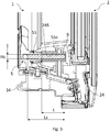
Fig. 5 is a sectional view of the bottom parts of the embodiment of the roof window shown inFigs 3 and4 ; -
Fig. 6 is a partial perspective view corresponding toFig. 3 , on a larger scale; -
Fig. 7 is an end view, on a larger scale, of the bushing in an embodiment of the roof window according to the invention; and -
Fig. 8 is a perspective view, on a larger scale, of the striking plate in the embodiment of the roof window shown inFig. 6 . - Referring initially to
Fig. 1 , the general configuration of a roof window is shown. - The roof window here comprises a primary frame in the form of a
stationary frame 1 configured for installation in an inclined roof surface, here by means ofmounting brackets 3 provided at the corners, but other installation principles may be applied as well. Theframe 1 comprises a plurality of frame members, here including a frametop member 11, twoframe side members frame bottom member 14. - At least one secondary frame is connected to the
stationary frame 1, in the embodiment shown asash 2 carrying apane 4. Thesash 2 is pivotally connected to thestationary frame 2 in order to be able to rotate thesash 2 to an open position. To that end, thesash 2 is provided hinge fitting part (not shown), cooperating with a counterpart hinge fitting part (not shown) provided on theframe 1. Thesash 2 comprises, corresponding to theframe 1, a sashtop member 21, twosash side members sash bottom member 24. In principle, the hinge axis could be located arbitrarily in the roof window, but is here substantially centre-hinged. The roof window could be top-hinged as well, meaning that the hinge axis is located near the frametop member 11 and the sashtop member 21. - From the shown closed position, the user operates the operating device of the window, here in the form of a
handle 5 at thebottom member 24 of thesash 2, interacting with astriking plate 8 fastened to thebottom member 14 of theframe 1. - Finally, the roof window is provided with a
ventilation device 6 accommodated in atop sash unit 7, acting to allow passage of air also in the closed position of the window. Further details of theventilation device 6 and thetop sash unit 7 are the subject of Applicant's co-pending patent application having the same filing date as the present application, and the contents thereof are incorporated herein by reference. - In the following, embodiments of the roof window will be described with particular focus on the
handle 5. - As mentioned, the operating means for opening and closing the
sash 2 relative to theframe 1 include thehandle 5 which is rotatably connected to thesash bottom member 24. Thehandle 5 comprises ashaft 55 with a predefined length Ls and at least one cross-sectional dimension Hs. Theshaft 55 could in principle have a number of cross-sectional configurations including for instance triangular or hexagonal, but in the embodiment shown, theshaft 55 has a substantially square cross-sectional configuration and the at least one cross-sectional dimension Hs is the side of the square. As indicated and shown most clearly inFig. 4 , theshaft 55 is here provided with chamfered edges. - The
shaft 55 is lodged in anaperture 245 in thesash bottom member 24, and has agrip 51 for a user to grasp and a peg orpawl 56 to interact with astriking plate 8 connected to theframe bottom member 14. Other components of thehandle 5 includecrank portion 52,console 53 andwasher 54. To fasten thehandle 5 to thesash bottom member 24,apertures 246 are provided for receiving fastening means such as screws which in the mounted condition are located within a removable part (not shown in detail) of theconsole 53. - During manufacture of the roof window, a shock-absorbing
bushing 9 is positioned on theshaft 55 to extend about theshaft 55 such that thebushing 9 envelops theshaft 55, at least partially, and thehandle 5 withbushing 9 is connected to thesash bottom member 24. For reasons of readability of the drawing, thebushing 9 is here shown as two halves. While the bushing could in principle be formed as a two-component element, it will be a single element in most applications. - The
bushing 9 has a predefined length L, at least one outer cross-sectional dimension D and anopening 92 with at least one cross-sectional dimension H. Referring toFig. 7 , theopening 92 in thebushing 9 has a substantially square configuration in the embodiment shown, and the at least one cross-sectional dimension H is the side of the square. At the corners of the square-shapedopening 92, rounded edges are provided. Thebushing 9 here has a substantially cylindrical cross-sectional configuration and the at least one outer cross-sectional dimension is the diameter D of thebushing 9. - It is preferable that the predefined length L of the
bushing 9 is chosen such that thebushing 9 extends about a major part of the length Ls of theshaft 55, preferably at least over 60% of the length Ls of theshaft 55. - In the embodiment shown, a
free portion 55a of theshaft 55 is lodged within thesash bottom member 24, substantially in its entirety, and here thebushing 9 extends about theshaft 55 over substantially the entirefree portion 55a of the length Ls of theshaft 55. In turn, this means that theshaft 5 is covered throughout its length located within thesash bottom member 24. - To hold the
bushing 9 on theshaft 55 of the handle, it is preferred that the cross-sectional dimension H of theopening 92 in thebushing 9 substantially corresponds to the cross-sectional dimension Hs of theshaft 55 such that an interference fit is provided between thebushing 9 and theshaft 55. - Correspondingly, the
aperture 245 in thesash bottom member 24 has a substantially cylindrical shape and an inner diameter substantially corresponding to the diameter D of thebushing 9. - The wall thickness of the
bushing 9 should be chosen such that satisfactory shock-absorbing properties are achieved, while at the same time a sufficient wearability is obtained. Measured as the ratio between the diameter D and the square side H of thebushing 9 of the embodiment shown, it is preferred that the ratio lies in the range 0.2 and 0.65, preferably in the range 0.4 to 0.6, more preferably in the range 0.55 to 0.59. Suitable dimensions ofbushing 9 are chosen in accordance with the physical requirements and material, but in typical examples the diameter D lies in the range 10 to 20 mm and the square side H in therange 5 to 10 mm. Here, H is about 8.3 mm and D is about 14.2 mm, hence the ratio is about 0.58. - The length L of the
bushing 9 is chosen in dependence of the components of the sash, but typically lies in the range 30 to 60 mm, preferably in the range 40 to 50 mm. Here, L is about 44 mm. - In principle, the
bushing 9 may be made from any suitable material meeting the demands to shock-absorbing properties and resistance to wear, but is advantageously made from a plastic material, such as a thermoplastic elastomer TPE. This material may easily and cost-effectively be provided as a moulded component for instance by extrusion or injection moulding. - The configuration of the
frame 1 and thesash 2 may in principle be compact wooden structures; however, in the embodiment shown at least thesash bottom member 24 is provided as a moulded component comprising ashell 240 of a plastic material, such as polyurethane PU, enclosing a set ofcore members shaft 55 of thehandle 5 is lodged, here denotedfirst core member 241, is made from a relatively stronger material than the other core members of the set, here second and thirdcore members Fig. 6 isrecess 249 which is present for manufacturing purposes, and the configuration of theframe bottom member 14 as comprisingshell 140 and first andsecond core members - Finally, the
striking plate 8 in theframe bottom member 14 comprises alock recess 81, corresponding to closed position of thesash 2 relative to theframe 1, and avent recess 82 allowing a slight opened position. Thestriking plate 8 is made from a plastic material reinforced by glass fibres. Furthermore, anaperture 83 for fastening means such as a screw is shown. - The invention is not limited to the embodiments shown and described in the above, but various modifications and combinations may be carried out.
-
- 1
- stationary frame
11 frame top member
12 frame side member
13 frame side member
14 frame bottom member - 2
- sash
21 sash top member
22 sash side member
23 sash side member
24 sash bottom member - 3
- mounting bracket
- 4
- pane
- 5
- handle
51 grip
52 crank portion
53 console
54 washer
55 shaft
55a free end of shaft
56 pawl - 6
- ventilation device
- 7
- top sash unit
- 8
- striking plate
81 lock recess
82 vent recess
83 aperture for fastening means - 9
- bushing
91 wall
92 hole - 140
- shell
- 141
- first core member
- 142
- second core member
- 240
- shell
- 241
- first core member
- 242
- second core member
- 243
- third core member
- 245
- shaft and bushing aperture
- 246
- apertures for fastening means
- 249
- recess
- H
- square side of
hole 92 inbushing 9 - D
- diameter of
bushing 9 - L
- length of
bushing 9 - Ls
- length of
shaft 55 - Hs
- square side of
shaft 55
Claims (14)
- A roof window comprising
a frame (1) having a plurality of frame members including a top member, two side members and a bottom member (11, 12, 13, 14),
a sash (2) having a plurality of sash members a top member, two side members and a bottom member (21, 22, 23, 24), and
operating means including a handle (5), said handle (5) being rotatably connected to a sash member (24) and comprising a shaft (55) with a predefined length (Ls) and at least one cross-sectional dimension (Hs) lodged in an aperture (245) in the sash member (24), a grip (51) and a pawl (56) to interact with a striking plate (8) connected to the frame member (14),
characterised in that
the handle (5) is connected to the sash bottom member (24) and is provided with a shock-absorbing bushing (9) having a predefined length (L), at least one outer cross-sectional dimension (D) and an opening (92) with at least one cross-sectional dimension (H), and extending about the shaft (55). - A roof window according to claim 1, wherein the predefined length (L) of the bushing (9) is chosen such that the bushing (9) extends about a major part of the length (Ls) of the shaft (55), preferably at least over 60% of the length (Ls) of the shaft (55).
- A roof window according to claim 2, wherein a free portion (55a) of the shaft (55) is lodged within the sash bottom member (24) and the bushing (9) extends about the shaft (55) over substantially the entire free portion (55a) of the length (Ls) of the shaft (55).
- A roof window according to any one of the preceding claims, wherein the at least one cross-sectional dimension (H) of the opening (92) in the bushing (9) substantially corresponds to the respective at least one cross-sectional dimension (Hs) of the shaft (55) such that an interference fit is provided between the bushing (9) and the shaft (55).
- A roof window according to claim 4, wherein the shaft (55) has a substantially square cross-sectional configuration and the at least one cross-sectional dimension (Hs) is the side of the square, preferably the shaft (55) has chamfered edges.
- A roof window according to claim 5, wherein the opening (92) in the bushing (9) has a substantially square configuration and the at least one cross-sectional dimension (H) is the side of the square, preferably the opening (92) has rounded edges.
- A roof window according to any one of the preceding claims, wherein the bushing (9) has a substantially cylindrical cross-sectional configuration and the at least one outer cross-sectional dimension is the diameter (D) of the bushing (9).
- A roof window according to claim 7, wherein the aperture (245) in the sash bottom member (24) has a substantially cylindrical shape and an inner diameter substantially corresponding to the diameter (D) of the bushing (9).
- A roof window according to any one of claims 7 and 8, wherein the ratio between the diameter (D) and the square side (H) of the bushing (9) lies in the range 0.2 and 0.65, preferably in the range 0.4 to 0.6, more preferably in the range 0.55 to 0.59.
- A roof window according to claim 9, wherein the diameter (D) lies in the range 10 to 20 mm and the square side (H) in the range 5 to 10 mm.
- A roof window according to any one of the preceding claims, wherein the length (L) of the bushing (9) lies in the range 30 to 60 mm, preferably in the range 40 to 50 mm.
- A roof window according to any one of the preceding claims, wherein the bushing (9) is made from a plastic material, such as a thermoplastic elastomer (TPE).
- A roof window according to any one of the preceding claims, wherein the sash bottom member (24) is provided as a moulded component comprising a shell (240) of a plastic material, such as polyurethane (PU), enclosing a set of core members (241, 242, 243), and wherein the core member (241) in which the shaft (55) of the handle (5) is lodged is made from a relatively stronger material than the other core members (242, 243) of said set.
- A roof window according to any one of the preceding claims, wherein the striking plate (8) in the frame bottom member (14) comprises a lock recess (81) and a vent recess (82), and is made from a plastic material reinforced by glass fibres.
Applications Claiming Priority (1)
| Application Number | Priority Date | Filing Date | Title |
|---|---|---|---|
| DKPA201870327A DK180304B1 (en) | 2018-06-06 | 2018-06-06 | Roof window with improved handle |
Publications (2)
| Publication Number | Publication Date |
|---|---|
| EP3578729A1 true EP3578729A1 (en) | 2019-12-11 |
| EP3578729B1 EP3578729B1 (en) | 2020-08-19 |
Family
ID=66770238
Family Applications (1)
| Application Number | Title | Priority Date | Filing Date |
|---|---|---|---|
| EP19178222.6A Active EP3578729B1 (en) | 2018-06-06 | 2019-06-04 | Roof window with improved handle |
Country Status (3)
| Country | Link |
|---|---|
| EP (1) | EP3578729B1 (en) |
| CN (1) | CN210828086U (en) |
| DK (1) | DK180304B1 (en) |
Cited By (1)
| Publication number | Priority date | Publication date | Assignee | Title |
|---|---|---|---|---|
| EP4279681B1 (en) | 2022-05-18 | 2025-05-07 | FAKRO PP Sp. z o.o. | Window frame with filling profile |
Citations (4)
| Publication number | Priority date | Publication date | Assignee | Title |
|---|---|---|---|---|
| FR2616832A1 (en) * | 1987-03-18 | 1988-12-23 | Giesse Spa | Large handle for doors and other opening panels of great weight or large size |
| US20080307836A1 (en) * | 2007-06-14 | 2008-12-18 | Hyundae Metal Co., Ltd. | Door handle module and door lock using the same |
| KR20090070449A (en) | 2007-12-27 | 2009-07-01 | 주식회사 엘지화학 | Cushion handle for small window sill |
| EP2751355A1 (en) | 2011-10-04 | 2014-07-09 | VKR Holding A/S | A roof window with a top sash module |
-
2018
- 2018-06-06 DK DKPA201870327A patent/DK180304B1/en not_active IP Right Cessation
-
2019
- 2019-06-04 EP EP19178222.6A patent/EP3578729B1/en active Active
- 2019-06-04 CN CN201920837714.6U patent/CN210828086U/en active Active
Patent Citations (4)
| Publication number | Priority date | Publication date | Assignee | Title |
|---|---|---|---|---|
| FR2616832A1 (en) * | 1987-03-18 | 1988-12-23 | Giesse Spa | Large handle for doors and other opening panels of great weight or large size |
| US20080307836A1 (en) * | 2007-06-14 | 2008-12-18 | Hyundae Metal Co., Ltd. | Door handle module and door lock using the same |
| KR20090070449A (en) | 2007-12-27 | 2009-07-01 | 주식회사 엘지화학 | Cushion handle for small window sill |
| EP2751355A1 (en) | 2011-10-04 | 2014-07-09 | VKR Holding A/S | A roof window with a top sash module |
Cited By (1)
| Publication number | Priority date | Publication date | Assignee | Title |
|---|---|---|---|---|
| EP4279681B1 (en) | 2022-05-18 | 2025-05-07 | FAKRO PP Sp. z o.o. | Window frame with filling profile |
Also Published As
| Publication number | Publication date |
|---|---|
| EP3578729B1 (en) | 2020-08-19 |
| DK201870327A1 (en) | 2020-01-14 |
| DK180304B1 (en) | 2020-10-26 |
| CN210828086U (en) | 2020-06-23 |
Similar Documents
| Publication | Publication Date | Title |
|---|---|---|
| US7669285B2 (en) | Damping device for furniture hinges | |
| EP1470313B1 (en) | Swing flap for the entry and exit of small pets with last transit direction indicator | |
| US9765559B2 (en) | Multi-directional rotational sliding door self-closing device | |
| US20050071953A1 (en) | Hinge | |
| AU2010285684A1 (en) | Door opening/closing system and catch therefor | |
| ITTO970121A1 (en) | DOOR POSITIONING HINGE. | |
| JP4881862B2 (en) | Coating equipment for aircraft hinges | |
| EP3578729B1 (en) | Roof window with improved handle | |
| US8024892B2 (en) | Drum housing | |
| KR101015071B1 (en) | Door hinge housing | |
| KR102469188B1 (en) | Safety Hinge | |
| KR20110011174U (en) | Angle adjustable door prevention equipment | |
| KR20110139362A (en) | Door hinge with fixture | |
| KR200340543Y1 (en) | Device for covering space between door frame and door | |
| EP3388288A1 (en) | Glove box of a dashboard of a motor vehicle | |
| EP2894284B1 (en) | Vehicle door latch device | |
| KR200386372Y1 (en) | Hinge structure for door reorganization | |
| KR100693352B1 (en) | Door magnet stopper | |
| KR100532267B1 (en) | The fixing a tool use of opening and closing door | |
| EP2726307B1 (en) | Tractor cab | |
| JP2020200677A (en) | door | |
| KR200272204Y1 (en) | protector for opening and closing type glass door | |
| KR200334758Y1 (en) | The fixing a tool use of opening and closing door | |
| KR20120031736A (en) | Strorage box with function for preventing noise | |
| KR960000869Y1 (en) | Door hinge structure |
Legal Events
| Date | Code | Title | Description |
|---|---|---|---|
| PUAI | Public reference made under article 153(3) epc to a published international application that has entered the european phase |
Free format text: ORIGINAL CODE: 0009012 |
|
| STAA | Information on the status of an ep patent application or granted ep patent |
Free format text: STATUS: THE APPLICATION HAS BEEN PUBLISHED |
|
| AK | Designated contracting states |
Kind code of ref document: A1 Designated state(s): AL AT BE BG CH CY CZ DE DK EE ES FI FR GB GR HR HU IE IS IT LI LT LU LV MC MK MT NL NO PL PT RO RS SE SI SK SM TR |
|
| AX | Request for extension of the european patent |
Extension state: BA ME |
|
| STAA | Information on the status of an ep patent application or granted ep patent |
Free format text: STATUS: REQUEST FOR EXAMINATION WAS MADE |
|
| 17P | Request for examination filed |
Effective date: 20200218 |
|
| RBV | Designated contracting states (corrected) |
Designated state(s): AL AT BE BG CH CY CZ DE DK EE ES FI FR GB GR HR HU IE IS IT LI LT LU LV MC MK MT NL NO PL PT RO RS SE SI SK SM TR |
|
| GRAP | Despatch of communication of intention to grant a patent |
Free format text: ORIGINAL CODE: EPIDOSNIGR1 |
|
| STAA | Information on the status of an ep patent application or granted ep patent |
Free format text: STATUS: GRANT OF PATENT IS INTENDED |
|
| RIC1 | Information provided on ipc code assigned before grant |
Ipc: E04D 13/035 20060101AFI20200309BHEP Ipc: E05B 1/00 20060101ALI20200309BHEP Ipc: E05C 3/04 20060101ALI20200309BHEP |
|
| INTG | Intention to grant announced |
Effective date: 20200330 |
|
| GRAS | Grant fee paid |
Free format text: ORIGINAL CODE: EPIDOSNIGR3 |
|
| GRAA | (expected) grant |
Free format text: ORIGINAL CODE: 0009210 |
|
| STAA | Information on the status of an ep patent application or granted ep patent |
Free format text: STATUS: THE PATENT HAS BEEN GRANTED |
|
| AK | Designated contracting states |
Kind code of ref document: B1 Designated state(s): AL AT BE BG CH CY CZ DE DK EE ES FI FR GB GR HR HU IE IS IT LI LT LU LV MC MK MT NL NO PL PT RO RS SE SI SK SM TR |
|
| REG | Reference to a national code |
Ref country code: CH Ref legal event code: EP |
|
| REG | Reference to a national code |
Ref country code: DE Ref legal event code: R096 Ref document number: 602019000502 Country of ref document: DE |
|
| REG | Reference to a national code |
Ref country code: AT Ref legal event code: REF Ref document number: 1304093 Country of ref document: AT Kind code of ref document: T Effective date: 20200915 |
|
| REG | Reference to a national code |
Ref country code: IE Ref legal event code: FG4D |
|
| REG | Reference to a national code |
Ref country code: NL Ref legal event code: FP |
|
| REG | Reference to a national code |
Ref country code: LT Ref legal event code: MG4D |
|
| PG25 | Lapsed in a contracting state [announced via postgrant information from national office to epo] |
Ref country code: BG Free format text: LAPSE BECAUSE OF FAILURE TO SUBMIT A TRANSLATION OF THE DESCRIPTION OR TO PAY THE FEE WITHIN THE PRESCRIBED TIME-LIMIT Effective date: 20201119 Ref country code: GR Free format text: LAPSE BECAUSE OF FAILURE TO SUBMIT A TRANSLATION OF THE DESCRIPTION OR TO PAY THE FEE WITHIN THE PRESCRIBED TIME-LIMIT Effective date: 20201120 Ref country code: HR Free format text: LAPSE BECAUSE OF FAILURE TO SUBMIT A TRANSLATION OF THE DESCRIPTION OR TO PAY THE FEE WITHIN THE PRESCRIBED TIME-LIMIT Effective date: 20200819 Ref country code: LT Free format text: LAPSE BECAUSE OF FAILURE TO SUBMIT A TRANSLATION OF THE DESCRIPTION OR TO PAY THE FEE WITHIN THE PRESCRIBED TIME-LIMIT Effective date: 20200819 Ref country code: PT Free format text: LAPSE BECAUSE OF FAILURE TO SUBMIT A TRANSLATION OF THE DESCRIPTION OR TO PAY THE FEE WITHIN THE PRESCRIBED TIME-LIMIT Effective date: 20201221 Ref country code: NO Free format text: LAPSE BECAUSE OF FAILURE TO SUBMIT A TRANSLATION OF THE DESCRIPTION OR TO PAY THE FEE WITHIN THE PRESCRIBED TIME-LIMIT Effective date: 20201119 Ref country code: SE Free format text: LAPSE BECAUSE OF FAILURE TO SUBMIT A TRANSLATION OF THE DESCRIPTION OR TO PAY THE FEE WITHIN THE PRESCRIBED TIME-LIMIT Effective date: 20200819 Ref country code: FI Free format text: LAPSE BECAUSE OF FAILURE TO SUBMIT A TRANSLATION OF THE DESCRIPTION OR TO PAY THE FEE WITHIN THE PRESCRIBED TIME-LIMIT Effective date: 20200819 |
|
| PG25 | Lapsed in a contracting state [announced via postgrant information from national office to epo] |
Ref country code: RS Free format text: LAPSE BECAUSE OF FAILURE TO SUBMIT A TRANSLATION OF THE DESCRIPTION OR TO PAY THE FEE WITHIN THE PRESCRIBED TIME-LIMIT Effective date: 20200819 Ref country code: LV Free format text: LAPSE BECAUSE OF FAILURE TO SUBMIT A TRANSLATION OF THE DESCRIPTION OR TO PAY THE FEE WITHIN THE PRESCRIBED TIME-LIMIT Effective date: 20200819 Ref country code: IS Free format text: LAPSE BECAUSE OF FAILURE TO SUBMIT A TRANSLATION OF THE DESCRIPTION OR TO PAY THE FEE WITHIN THE PRESCRIBED TIME-LIMIT Effective date: 20201219 |
|
| PG25 | Lapsed in a contracting state [announced via postgrant information from national office to epo] |
Ref country code: EE Free format text: LAPSE BECAUSE OF FAILURE TO SUBMIT A TRANSLATION OF THE DESCRIPTION OR TO PAY THE FEE WITHIN THE PRESCRIBED TIME-LIMIT Effective date: 20200819 Ref country code: RO Free format text: LAPSE BECAUSE OF FAILURE TO SUBMIT A TRANSLATION OF THE DESCRIPTION OR TO PAY THE FEE WITHIN THE PRESCRIBED TIME-LIMIT Effective date: 20200819 Ref country code: DK Free format text: LAPSE BECAUSE OF FAILURE TO SUBMIT A TRANSLATION OF THE DESCRIPTION OR TO PAY THE FEE WITHIN THE PRESCRIBED TIME-LIMIT Effective date: 20200819 Ref country code: SM Free format text: LAPSE BECAUSE OF FAILURE TO SUBMIT A TRANSLATION OF THE DESCRIPTION OR TO PAY THE FEE WITHIN THE PRESCRIBED TIME-LIMIT Effective date: 20200819 |
|
| REG | Reference to a national code |
Ref country code: DE Ref legal event code: R097 Ref document number: 602019000502 Country of ref document: DE |
|
| PG25 | Lapsed in a contracting state [announced via postgrant information from national office to epo] |
Ref country code: AL Free format text: LAPSE BECAUSE OF FAILURE TO SUBMIT A TRANSLATION OF THE DESCRIPTION OR TO PAY THE FEE WITHIN THE PRESCRIBED TIME-LIMIT Effective date: 20200819 Ref country code: ES Free format text: LAPSE BECAUSE OF FAILURE TO SUBMIT A TRANSLATION OF THE DESCRIPTION OR TO PAY THE FEE WITHIN THE PRESCRIBED TIME-LIMIT Effective date: 20200819 |
|
| PLBE | No opposition filed within time limit |
Free format text: ORIGINAL CODE: 0009261 |
|
| STAA | Information on the status of an ep patent application or granted ep patent |
Free format text: STATUS: NO OPPOSITION FILED WITHIN TIME LIMIT |
|
| PG25 | Lapsed in a contracting state [announced via postgrant information from national office to epo] |
Ref country code: SK Free format text: LAPSE BECAUSE OF FAILURE TO SUBMIT A TRANSLATION OF THE DESCRIPTION OR TO PAY THE FEE WITHIN THE PRESCRIBED TIME-LIMIT Effective date: 20200819 |
|
| 26N | No opposition filed |
Effective date: 20210520 |
|
| PG25 | Lapsed in a contracting state [announced via postgrant information from national office to epo] |
Ref country code: IT Free format text: LAPSE BECAUSE OF FAILURE TO SUBMIT A TRANSLATION OF THE DESCRIPTION OR TO PAY THE FEE WITHIN THE PRESCRIBED TIME-LIMIT Effective date: 20200819 |
|
| PG25 | Lapsed in a contracting state [announced via postgrant information from national office to epo] |
Ref country code: MC Free format text: LAPSE BECAUSE OF FAILURE TO SUBMIT A TRANSLATION OF THE DESCRIPTION OR TO PAY THE FEE WITHIN THE PRESCRIBED TIME-LIMIT Effective date: 20200819 |
|
| PG25 | Lapsed in a contracting state [announced via postgrant information from national office to epo] |
Ref country code: LU Free format text: LAPSE BECAUSE OF NON-PAYMENT OF DUE FEES Effective date: 20210604 |
|
| PG25 | Lapsed in a contracting state [announced via postgrant information from national office to epo] |
Ref country code: IE Free format text: LAPSE BECAUSE OF NON-PAYMENT OF DUE FEES Effective date: 20210604 |
|
| REG | Reference to a national code |
Ref country code: AT Ref legal event code: UEP Ref document number: 1304093 Country of ref document: AT Kind code of ref document: T Effective date: 20200819 |
|
| REG | Reference to a national code |
Ref country code: CH Ref legal event code: PL |
|
| PG25 | Lapsed in a contracting state [announced via postgrant information from national office to epo] |
Ref country code: LI Free format text: LAPSE BECAUSE OF NON-PAYMENT OF DUE FEES Effective date: 20220630 Ref country code: CH Free format text: LAPSE BECAUSE OF NON-PAYMENT OF DUE FEES Effective date: 20220630 |
|
| PG25 | Lapsed in a contracting state [announced via postgrant information from national office to epo] |
Ref country code: CY Free format text: LAPSE BECAUSE OF FAILURE TO SUBMIT A TRANSLATION OF THE DESCRIPTION OR TO PAY THE FEE WITHIN THE PRESCRIBED TIME-LIMIT Effective date: 20200819 |
|
| PG25 | Lapsed in a contracting state [announced via postgrant information from national office to epo] |
Ref country code: HU Free format text: LAPSE BECAUSE OF FAILURE TO SUBMIT A TRANSLATION OF THE DESCRIPTION OR TO PAY THE FEE WITHIN THE PRESCRIBED TIME-LIMIT; INVALID AB INITIO Effective date: 20190604 |
|
| PG25 | Lapsed in a contracting state [announced via postgrant information from national office to epo] |
Ref country code: SI Free format text: LAPSE BECAUSE OF FAILURE TO SUBMIT A TRANSLATION OF THE DESCRIPTION OR TO PAY THE FEE WITHIN THE PRESCRIBED TIME-LIMIT Effective date: 20200819 |
|
| PG25 | Lapsed in a contracting state [announced via postgrant information from national office to epo] |
Ref country code: MK Free format text: LAPSE BECAUSE OF FAILURE TO SUBMIT A TRANSLATION OF THE DESCRIPTION OR TO PAY THE FEE WITHIN THE PRESCRIBED TIME-LIMIT Effective date: 20200819 |
|
| PG25 | Lapsed in a contracting state [announced via postgrant information from national office to epo] |
Ref country code: TR Free format text: LAPSE BECAUSE OF FAILURE TO SUBMIT A TRANSLATION OF THE DESCRIPTION OR TO PAY THE FEE WITHIN THE PRESCRIBED TIME-LIMIT Effective date: 20200819 |
|
| PG25 | Lapsed in a contracting state [announced via postgrant information from national office to epo] |
Ref country code: MT Free format text: LAPSE BECAUSE OF FAILURE TO SUBMIT A TRANSLATION OF THE DESCRIPTION OR TO PAY THE FEE WITHIN THE PRESCRIBED TIME-LIMIT Effective date: 20200819 |
|
| PGFP | Annual fee paid to national office [announced via postgrant information from national office to epo] |
Ref country code: NL Payment date: 20250516 Year of fee payment: 7 |
|
| PGFP | Annual fee paid to national office [announced via postgrant information from national office to epo] |
Ref country code: PL Payment date: 20250515 Year of fee payment: 7 Ref country code: DE Payment date: 20250507 Year of fee payment: 7 |
|
| PGFP | Annual fee paid to national office [announced via postgrant information from national office to epo] |
Ref country code: GB Payment date: 20250501 Year of fee payment: 7 |
|
| PGFP | Annual fee paid to national office [announced via postgrant information from national office to epo] |
Ref country code: BE Payment date: 20250516 Year of fee payment: 7 |
|
| PGFP | Annual fee paid to national office [announced via postgrant information from national office to epo] |
Ref country code: FR Payment date: 20250523 Year of fee payment: 7 |
|
| PGFP | Annual fee paid to national office [announced via postgrant information from national office to epo] |
Ref country code: AT Payment date: 20250528 Year of fee payment: 7 |
|
| PGFP | Annual fee paid to national office [announced via postgrant information from national office to epo] |
Ref country code: CZ Payment date: 20250529 Year of fee payment: 7 |