EP3578720A1 - Lifting and lowering device for construction machine - Google Patents
Lifting and lowering device for construction machine Download PDFInfo
- Publication number
- EP3578720A1 EP3578720A1 EP18831765.5A EP18831765A EP3578720A1 EP 3578720 A1 EP3578720 A1 EP 3578720A1 EP 18831765 A EP18831765 A EP 18831765A EP 3578720 A1 EP3578720 A1 EP 3578720A1
- Authority
- EP
- European Patent Office
- Prior art keywords
- pivotally supported
- lifting
- movable ladder
- ladder
- lowering device
- Prior art date
- Legal status (The legal status is an assumption and is not a legal conclusion. Google has not performed a legal analysis and makes no representation as to the accuracy of the status listed.)
- Granted
Links
Images

Classifications
-
- E—FIXED CONSTRUCTIONS
- E02—HYDRAULIC ENGINEERING; FOUNDATIONS; SOIL SHIFTING
- E02F—DREDGING; SOIL-SHIFTING
- E02F9/00—Component parts of dredgers or soil-shifting machines, not restricted to one of the kinds covered by groups E02F3/00 - E02F7/00
- E02F9/08—Superstructures; Supports for superstructures
- E02F9/0833—Improving access, e.g. for maintenance, steps for improving driver's access, handrails
-
- B—PERFORMING OPERATIONS; TRANSPORTING
- B60—VEHICLES IN GENERAL
- B60R—VEHICLES, VEHICLE FITTINGS, OR VEHICLE PARTS, NOT OTHERWISE PROVIDED FOR
- B60R3/00—Arrangements of steps or ladders facilitating access to or on the vehicle, e.g. running-boards
- B60R3/02—Retractable steps or ladders, e.g. movable under shock
-
- E—FIXED CONSTRUCTIONS
- E06—DOORS, WINDOWS, SHUTTERS, OR ROLLER BLINDS IN GENERAL; LADDERS
- E06C—LADDERS
- E06C5/00—Ladders characterised by being mounted on undercarriages or vehicles Securing ladders on vehicles
- E06C5/02—Ladders characterised by being mounted on undercarriages or vehicles Securing ladders on vehicles with rigid longitudinal members
- E06C5/04—Ladders characterised by being mounted on undercarriages or vehicles Securing ladders on vehicles with rigid longitudinal members capable of being elevated or extended ; Fastening means during transport, e.g. mechanical, hydraulic
- E06C5/06—Ladders characterised by being mounted on undercarriages or vehicles Securing ladders on vehicles with rigid longitudinal members capable of being elevated or extended ; Fastening means during transport, e.g. mechanical, hydraulic by piston and cylinder, or equivalent means, operated by a pressure medium
Definitions
- the present invention relates to a lifting and lowering device used for a large-sized construction machine.
- a revolving body On a construction machine such as a hydraulic excavator and a loader shovel which are large-sized, a revolving body is attached via a revolving device on a traveling body, a cab is installed on the revolving body, and a multi-articulated front for excavation is attached.
- a large-sized construction machine since the revolving body is located in a high place with respect to a height of an operator, the operator cannot ascend to and descend from the revolving body without using some lifting and lowering device.
- a hydraulic excavator described in Patent Document 1 includes a lifting and lowering device constituted of a retractable ladder.
- a base end of the ladder is connected to a sidewalk on a revolving body, and the ladder is driven by a hydraulic cylinder and is thereby revolvable with the base end as a center.
- the ladder is held in a retracted position in such a way as to stand upright on the sidewalk.
- the ladder When an operator descents from a cab after finishing the operation, the ladder is driven by the hydraulic cylinder and is thereby revolved with the base end as the center in such a way as to fall down to a side of the hydraulic excavator, and a leading end thereof is located in the vicinity of a ground surface.
- the operator climbs down the ladder and can thereby descend to the ground surface, and also upon starting the operation next day, the operator climbs up the ladder and can thereby ascend to the revolving body.
- a lifting and lowering device constituted of a foldable two-stage type ladder has been put into practical use.
- a base end of a first ladder is revolvably connected to a sidewalk of a revolving body, and a base end of a second ladder is revolvably connected to a leading end of the first ladder.
- the first ladder is driven by a hydraulic cylinder and thereby is revolved between a retracted position and an extended position, and that movement is transmitted via a four-articulated link mechanism to the second ladder.
- the second ladder With the first ladder in the retracted position, the second ladder is folded and superposed on the first ladder, and with the first ladder in the extended position, the second ladder is extended, and a leading end of the second ladder is located in the vicinity of a ground surface.
- Patent Document 1 WO2017002160
- the long ladder which stands upright on the sidewalk in the retracted position hinders a field of view of the operator and causes a center of gravity of the construction machine to be high and thereby makes the construction machine, which sways when traveling on a rough road, unstable, thus leading to a factor of deterioration in workability.
- the lifting and lowering device which includes the two-stage type ladder a problem in costs, which is attributable to a structure of the ladder which is foldable, has arisen.
- manufacturing and assembling of components of the four-articulated link mechanism via which the second ladder is revolved in conjunction with the first ladder are cumbersome, manufacturing costs thereof are expensive, and costs for maintenance such as replacement of worn bearings are required.
- manufacturing costs of the pair of ladders are expensive, as compared with the one-stage type ladder, and due to these factors, for example, as compared with the lifting and lowering device having the one-stage type ladder, the lifting and lowering device having the two-stage type ladder is disadvantageous in terms of costs.
- the complicated structure of the lifting and lowering device including the two-stage type ladder due to the four-articulated link mechanism has room for improvement also in terms of durability and reliability.
- An object of the present invention is to provide a lifting and lowering device for a construction machine, which can be installed without imparting any restrictions in a structure and work to a construction machine and allows costs required for manufacturing and maintenance to be reduced and further, is excellent in durability and reliability.
- a lifting and lowering device for a construction machine includes: a supporting member being provided in a revolving body of the construction machine; a movable ladder having steps allowing an operator to climb up and down; a trajectory restricting member whose one end is pivotally supported on the supporting member in a swingable manner and whose another end is pivotally supported on the movable ladder in the swingable manner, the trajectory restricting member restricting a movement trajectory of a pivotally supported part at the other end to be of a shape of an arc with a pivotally supported part at the one end as a center; a cooperative rod member whose one end is pivotally supported on the supporting member in the swingable manner and whose another end is pivotally supported in the swingable manner in a position being away from the pivotally supported part of the trajectory restricting member on the movable ladder; and a first hydraulic cylinder whose one end is pivotally supported in the swingable manner in a position being away from a pivotally supported
- a lifting and lowering device for a construction machine switches a position of a movable ladder by causing a cooperative rod member and a first hydraulic cylinder to cooperate with each other and thereby moving pivotally supported parts in common with each other, thus reducing a load exerted on the first hydraulic cylinder, restraining a movement path of the movable ladder in a small area, and lowering a height of the movable ladder in a retracted position.
- the lifting and lowering device for a construction machine can be installed without imparting any restrictions in a structure and work to a construction machine.
- the lifting and lowering device for a construction machine allows costs required for manufacturing and maintenance to be reduced and is excellent in durability and reliability.
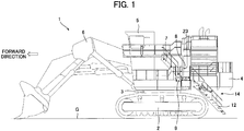
- FIG. 1 is a side view illustrating a hydraulic excavator which is equipped with a lifting and lowering device of the present embodiment.
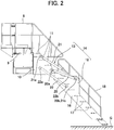
- FIG. 2 is a detailed view illustrating the lifting and lowering device in an extended position, corresponding to FIG. 1 .
- a right-left direction in FIG. 1 is referred to as a backward-forward direction
- a direction which is orthogonal to a paper surface is referred to as a right-left direction.
- a revolving body 4 is attached via a revolving device 3, and on the revolving body 4, a cab 5 is installed, and on a right side of the cab, a multi-articulated front 6 for excavation is attached in such a way as to face forward.
- a fixed ladder 7 is provided in such a way as to descend backward.
- a sidewalk 9 which includes a handrail 8 is horizontally installed in such a way as to bulge toward a left side from the revolving body 4.
- a pair of right and left supporting bases 10, each of which is flat plate-shaped, are fixed, and between the supporting bases 10, three auxiliary steps 11 are provided.
- a movable ladder 12 is installed.
- This movable ladder 12 is supported by lifting and lowering mechanisms 13 provided on the supporting bases 10 of the sidewalk 9, and a position in which the movable ladder 12 is located is switched between a retracted position in which the movable ladder 12 is retracted to a side of the revolving body 4 and an extended position in which an operator can climb up from a ground surface G and climb down to the ground surface G.
- a lifting and lowering device 14 of the present embodiment is constituted of these movable ladder 12 and the lifting and lowering mechanisms 13.
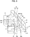
- FIG. 3 is a detailed view illustrating the lifting and lowering device 14 in a retracted position.
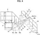
- FIG. 4 is a detailed view illustrating the lifting and lowering device 14 in the middle of switching between an extended position and the retracted position.
- the movable ladder 12 as a whole is configured by connecting a pair of right and left ladder frames 16, each of which is flat plate-shaped, by a multitude of steps 17.
- the respective steps 17 are provided in such a way as to line up at predetermined intervals in a longitudinal direction of the movable ladder 12.
- Handrails 18 are fixed to the right and left ladder frames 16, respectively.
- the movable ladder 12 is held in a posture in which the movable ladder 12 is inclined backward in a descending direction.
- an upper end of the movable ladder 12 is in proximity to the sidewalk 9.
- An uppermost step 17 is connected to the above-mentioned auxiliary steps 11, whereby a length of the movable ladder 12 is supplemented by the auxiliary steps 11.
- a lower end of the movable ladder 12 is located in the vicinity of the ground surface G.
- the movable ladder 12 in the retracted position is located above the sidewalk 9 in a posture similar to a posture in which the movable ladder 12 is in the extended position. Therefore, as shown in FIG. 3 , a position of the lower end of the movable ladder 12 substantially coincides with a position of a lowermost portion of the sidewalk 9 in a height direction, and the movable ladder 12 is thereby prevented from interfering with the traveling body 2 upon revolving of the revolving body 4.
- the lifting and lowering mechanisms 13 are disposed on right and left sides of the sidewalk 9 and the movable ladder 12, respectively. Since the right and left lifting and lowering mechanisms 13 have totally identical configurations, hereinafter, as a representative, the lifting and lowering mechanism on a left side will be described.
- the lifting and lowering mechanism 13 is constituted of a pair of first and second hydraulic cylinders 20 and 21, which operate in cooperation with each other, and trajectory restricting members 22.
- the trajectory restricting members 22 which are rod-shaped connect the sidewalk 9 and the movable ladder 12. Specifically, one ends of the trajectory restricting members 22 are pivotally supported by the supporting base 10 of the sidewalk 9 in a swingable manner (hereinafter, referred to as pivotally supported parts 22a), and other ends of the trajectory restricting members 22 are pivotally supported on a ladder frame 16 of the movable ladder 12 in the swingable manner (hereinafter, referred to as pivotally supported parts 22b).
- a movement trajectory of the pivotally supported parts 22b at the other ends of the trajectory restricting members 22 is restricted to be of a shape of an arc with the pivotally supported parts 22a at the one ends of the trajectory restricting members 22 on a side of the supporting base 10 as a center, and the movable ladder 12 can also move along an arc-shaped trajectory together with the pivotally supported parts 22b at the other ends thereof.
- first and second hydraulic cylinders 20 and 21 are connected to the sidewalk 9 and the movable ladder 12.
- main body base ends 20a and 21a of the first and second hydraulic cylinders 20 and 21 (which correspond to one end of the present invention) are pivotally supported in the swingable manner in positions on the supporting base 10 of the sidewalk 9 which are apart from each other and which are also away from the pivotally supported parts 22a of the one ends (hereinafter, referred to as pivotally supported parts 20a and pivotally supported parts 21a).
- rod tip ends 20b and 21b of the first and second hydraulic cylinders 20 and 21 are pivotally supported in the swingable manner in a common position on the ladder frame 16 of the movable ladder 12 (hereinafter, referred to as in-common pivotally supported parts 20b and 21b).
- These in-common pivotally supported parts 20b and 21b are away from at a predetermined interval from the pivotally supported parts 22b at the other ends of the trajectory restricting members 22.
- the main body base ends 20a and 21a and the rod tip ends 20b and 21b of the hydraulic cylinders 20 and 21 may be disposed in a manner opposite to the above-mentioned manner.
- the left side of the movable ladder 12 is supported from a side of the sidewalk 9 at a total of two points of a point of the pivotally supported parts 22b via the trajectory restricting members 22 and a point shared by the in-common pivotally supported parts 20b and 21b via the first and second hydraulic cylinders 20 and 21.
- the lifting and lowering mechanism 13 of the movable ladder 12 on a right side has the identical configuration as mentioned above, as a result, the movable ladder 12 is supported from the side of the sidewalk 9 at a total of four points by the right and left lifting and lowering mechanisms 13.
- the right and left first second hydraulic cylinders 20 operate in synchronization with each other, whereby while the movable ladder 12 is being prevented from inclining in a right-left direction, the movable ladder 12 is retained in a posture and a position in accordance with operation of the hydraulic cylinders 20 and 21 as described below.
- a position of the in-common pivotally supported parts 20b and 21b of the movable ladder 12 is displaced in accordance with a retracting or extending state of rods of the hydraulic cylinders 20 and 21.
- one end of a movement trajectory of the in-common pivotally supported parts 20b and 21b comes to a position when the first hydraulic cylinders 20 shown in FIG. 2 are most contracted (hereinafter, referred to as a contracted position) and comes to a position when the second hydraulic cylinders 21 shown in FIG. 2 are most extended (hereinafter, referred to as an extended position).
- another end of the movement trajectory of the in-common pivotally supported parts 20b and 21b comes to a position when the first hydraulic cylinders 20 shown in FIG. 3 are located in the extended position and when the second hydraulic cylinders 21 shown in FIG. 3 are located in the contracted position.
- a trajectory along which the in-common pivotally supported parts 20b and 21b move between one end and the other end of the movement trajectory depends on operation timing of both of the hydraulic cylinders 20 and 21.
- operation of another of the hydraulic cylinders 20 and 21 is started.
- the present invention is not limited thereto, and for example, one of the hydraulic cylinders 20 and 21 and the other of the hydraulic cylinders 20 and 21 may be operated in parallel with each other.
- the position of the in-common pivotally supported parts 20b and 21b is determined.
- the pivotally supported parts 22b at the other ends of the trajectory restricting members 22 are invariably retained at the predetermined interval from the in-common pivotally supported parts 20b and 21b, and the movement trajectory of the pivotally supported parts 22b is restricted to be of the arc shape via the trajectory restricting members 22.
- a posture and a position of the movable ladder 12 is spontaneously determined.
- the first and second hydraulic cylinders 20 and 21 are connected with a hydraulic circuit, not shown, and a switching valve of the hydraulic circuit is switched in accordance with operation of a lifting and lowering switch 23 provided in the vicinity of the sidewalk 9, and in accordance therewith, the right and left first and second hydraulic cylinders 20 and 21 operate. Note that the extended position and the contracted position of each of the hydraulic cylinders 20 and 21 are set to be immediately before stroke ends for seal protection. Hereinafter, a specific operation state of the lifting and lowering device 14 will be described.
- the right and left first hydraulic cylinders 20 are operated in extended directions in synchronization therewith (invariably operated with the same strokes).
- the in-common pivotally supported parts 20b and 21b of the first hydraulic cylinders 20 and the second hydraulic cylinders 21 move substantially upward along a trajectory which approximates an arc.
- the pivotally supported parts 22b at the other ends of the trajectory restricting members 22 are invariably retained at the predetermined interval from the in-common pivotally supported parts 20b and 21b, and the movement trajectory thereof is restricted to be of the arc shape via the trajectory restricting members 22. Therefore, in conjunction with the displacement of the position of the in-common pivotally supported parts 20b and 21b, a position of the pivotally supported parts 22b at the other ends of the trajectory restricting members 22 is invariably settled at one point, and in accordance with the positional relationship of these two points, the posture and the position of the movable ladder 12 are spontaneously determined. As shown in FIG. 4 , at a point in time when the right and left first hydraulic cylinders 20 have reached the extended positions, the movable ladder 12 is performing an upward translational motion while substantially retaining a posture in the extended position.
- the right and left second hydraulic cylinders 21 are operated in contracted directions in synchronization therewith (invariably operated with the same strokes), and in accordance with the contraction thereof, the in-common pivotally supported parts 20b and 21b of the first hydraulic cylinders 20 and the second hydraulic cylinders 21 move upward and forward along the trajectory which approximates the arc.
- the movable ladder 12 is performing a forward and upward translational motion while substantially retaining a posture in the extended position and reaches the retracted position above the sidewalk 9.
- the operator gets in the cab 5 and can start the work by the hydraulic excavator 1.
- the lifting and lowering switch 23 is operated to select an extended direction by the operator in order for the operator to descend from the cab 5 to the ground surface G after finishing the operation, first, the right and left second hydraulic cylinders 21 are operated in the extended direction in synchronization therewith.
- the in-common pivotally supported parts 20b and 21b of the first hydraulic cylinders 20 and the second hydraulic cylinders 21 move backward and downward along the trajectory which approximates the arc.
- the movable ladder 12 is performing a backward and downward translational motion while substantially retaining a posture in the retracted position.
- the right and left first hydraulic cylinders 20 are operated in contracted directions in synchronization therewith, and in accordance with the contraction thereof, the in-common pivotally supported parts 20b and 21b of the first hydraulic cylinders 20 and the second hydraulic cylinders 21 move downward along the trajectory which approximates the arc.
- the movable ladder 12 is performing a downward translational motion while retaining the posture in the retracted position and reaches the extended position in which a lower end thereof is located in the vicinity of the ground surface G.
- the operator climbs down the movable ladder 12 and can descend to the ground surface G and upon starting work the next day, climbs up the movable ladder 12 and can ascend to the sidewalk 9.
- the operating principle of the lifting and lowering mechanisms 13 is characterized in that the right and left first and second hydraulic cylinders 20 and 21 which are pivotally supported at the common positions with respect to the movable ladder 12 are operated sequentially (or in parallel with each other) and respective cylinder strokes are converted into lifting and lowering strokes of the movable ladder 12 by mutual cooperation thereof without waste.
- the first and second hydraulic cylinders 20 and 21 are retained in the arrangement substantially in parallel with each other while sharing the pivotally supported parts 20b and 21b, and the trajectory restricting members 22 are also retained in the arrangement substantially in parallel with these hydraulic cylinders 20 and 21.
- the lifting and lowering strokes of the movable ladder 12 between the extended position and the retracted position are ensured, and at the same time, the right and left lifting and lowering mechanisms 13 are invariably retained in one collective small space of occupancy. Accordingly, not only the lifting and lowering mechanisms 13 are installed between the sidewalk 9 and the movable ladder 12 with no difficulty, but also in any of the extended position and the retracted position, the operator can act on the movable ladder 12 and the sidewalk 9 without being hindered by the lifting and lowering mechanisms 13, thus allowing high functionality of the lifting and lowering device 14 to be realized.
- the lifting and lowering device in Patent Document 1 in order to prevent interference upon revolving the long ladder, a large space is required.
- the movable ladder 12 of the present embodiment performs the translational motion without substantially changing the posture between the extended position and the retracted position, a movement path is restrained in a minimum area.
- the movement path of the movable ladder 12 is in the area from behind the sidewalk 9 (the extended position) up to above the sidewalk 9 (the retracted position), that is, an area in which nothing is originally installed.
- the lifting and lowering device 14 of the present embodiment can be installed without exerting any influence on the existing facilities and apparatuses with which the revolving body 4 is provided.
- the long ladder in Patent Document 1 in the retracted position in which the long ladder stands upright hinders a field of view of the operator and causes a center of gravity of the construction machine to be high and thereby makes the construction machine unstable during traveling.
- a lower end thereof in the retracted position of the movable ladder 12 of the present embodiment is located at the lowest height (which substantially coincides the lowermost portion of the sidewalk 9) at which revolving of the revolving body 4 is not hindered.
- the movable ladder 12 since unlike the ladder in Patent Document 1, the movable ladder 12 does not stand upright and retains the inclined posture similar to that in the extended position due to the translational motion, a height of an upper end thereof is remarkably low.
- auxiliary steps 11 installed on the supporting bases 10 of the sidewalk 9 serve to supplement a length of the movable ladder 12.
- an overall length of the movable ladder 12 can be shortened by a path length of the auxiliary steps 11, also thereby greatly contributing to restraining of a height of the movable ladder 12 in the retracted position.
- the lifting and lowering device 14 does not cause a position of a center of gravity of the hydraulic excavator 1 to be heightened, thus allowing the hydraulic excavator 1 to stably travel on a rough road.
- the lifting and lowering device 14 of the present embodiment can be installed without imparting any restrictions in a structure and work to the hydraulic excavator 1.
- the lifting and lowering device which includes the conventional foldable two-stage type ladder (hereinafter, referred to as the conventional lifting and lowering device in order to distinguish that in Patent Document 1)
- manufacturing costs and maintenance costs related to the four-articulated link mechanism which causes the ladders to operate in conjunction with each other, are required and moreover, manufacturing costs of the pair of ladders are also high.
- the lifting and lowering device 14 of the present embodiment does not require the four-articulated link mechanism having the complicated structure, the number of the hydraulic cylinders 20 and 21 increases.
- the lifting and lowering device 14 of the present embodiment not only allows costs required for manufacturing and maintenance to be considerably reduced but also is remarkably excellent in durability and reliability.
- FIG. 5 is a detailed view illustrating a lifting and lowering device 14 of another example in an extended position, corresponding to FIG. 1 .
- the second hydraulic cylinders 21 of the embodiment are replaced with retractable rod members 31, and the other components are the same as those in the embodiment. Therefore, the same components are denoted by the same reference signs as those in the embodiment, the description therefor is omitted, and the description will be given by focusing on differences.
- the retractable rod members 31 are constituted of outer rods 31a on a side of the sidewalk 9 and inner rods 31b on a side of the movable ladder 12.
- the inner rods 31b are relatively inserted into the outer rods 31a in a slidable manner, thereby configuring the retractable rod members 31 in a retractable manner.
- the lifting and lowering device 14 is driven only by the first hydraulic cylinders 20.
- the first hydraulic cylinders 20 operate in an extended direction
- the retractable rod members 31 operate in a contracted direction in accordance with extension of the first hydraulic cylinders 20.
- a position of the lifting and lowering device 14 shifts via the position shown in FIG. 4 as described in the first embodiment to the retracted position shown in FIG. 3 .
- the first hydraulic cylinders 20 may be replaced with the retractable rod members 31, and also in this case, an operating state is similar to the above-described operating state.
- respective settings (the pivotally supported positions, the cylinder strokes, and the like of the hydraulic cylinders 20 and 21 and the trajectory restricting members 22) of the lifting and lowering mechanisms 13 are determined such that the movable ladder 12 is caused to perform the translational motion and can thereby retain the posture in the extended position up to when the movable ladder 12 comes in the retracted position.
- the settings of the pivotally supported positions of the hydraulic cylinders 20 and 21 and the trajectory restricting members 22 are not limited to those in the embodiment.
- one ends 22a of the trajectory restricting members 22 and the main body base ends 21a of the second hydraulic cylinders 21 may be pivotally supported in a common position.
- the lifting and lowering mechanisms 13 operate without hindrance, and by sharing the pivotally supported positions, the structure is simplified, thus allowing manufacturing costs to be further reduced.
- the present invention is embodied as the lifting and lowering device for the hydraulic excavator 1, a construction machine to which the present invention is applied is not limited to this and can be optionally modified.
Landscapes
- Engineering & Computer Science (AREA)
- Mechanical Engineering (AREA)
- Mining & Mineral Resources (AREA)
- Civil Engineering (AREA)
- General Engineering & Computer Science (AREA)
- Structural Engineering (AREA)
- Vehicle Step Arrangements And Article Storage (AREA)
- Component Parts Of Construction Machinery (AREA)
- Ladders (AREA)
Abstract
Description
- The present invention relates to a lifting and lowering device used for a large-sized construction machine.
- On a construction machine such as a hydraulic excavator and a loader shovel which are large-sized, a revolving body is attached via a revolving device on a traveling body, a cab is installed on the revolving body, and a multi-articulated front for excavation is attached. On such a large-sized construction machine, since the revolving body is located in a high place with respect to a height of an operator, the operator cannot ascend to and descend from the revolving body without using some lifting and lowering device.
- Therefore, for example, a hydraulic excavator described in
Patent Document 1 includes a lifting and lowering device constituted of a retractable ladder. A base end of the ladder is connected to a sidewalk on a revolving body, and the ladder is driven by a hydraulic cylinder and is thereby revolvable with the base end as a center. During operation of the hydraulic excavator, the ladder is held in a retracted position in such a way as to stand upright on the sidewalk. When an operator descents from a cab after finishing the operation, the ladder is driven by the hydraulic cylinder and is thereby revolved with the base end as the center in such a way as to fall down to a side of the hydraulic excavator, and a leading end thereof is located in the vicinity of a ground surface. Thus, the operator climbs down the ladder and can thereby descend to the ground surface, and also upon starting the operation next day, the operator climbs up the ladder and can thereby ascend to the revolving body. - On the other hand, instead of one-stage type ladder as with the lifting and lowering device in
Patent Document 1, a lifting and lowering device constituted of a foldable two-stage type ladder has been put into practical use. In the above-mentioned conventional lifting and lowering device, a base end of a first ladder is revolvably connected to a sidewalk of a revolving body, and a base end of a second ladder is revolvably connected to a leading end of the first ladder. The first ladder is driven by a hydraulic cylinder and thereby is revolved between a retracted position and an extended position, and that movement is transmitted via a four-articulated link mechanism to the second ladder. With the first ladder in the retracted position, the second ladder is folded and superposed on the first ladder, and with the first ladder in the extended position, the second ladder is extended, and a leading end of the second ladder is located in the vicinity of a ground surface. - Patent Document 1:
WO2017002160 - However, as to the lifting and lowering device described in
Patent Document 1, structural and operational problems of a construction machine, which are attributable to the long one-stage type ladder, have arisen. For example, when the sidewalk has a height of 4 m, a length of the ladder which is located in an inclined manner when the ladder is extended reaches approximately 5 m. In order to revolve the long ladder, a large load is exerted on the hydraulic cylinder, and because in order to prevent interference thereof upon revolving, a large space is required, a structure of the construction machine is greatly constrained. - In addition, the long ladder which stands upright on the sidewalk in the retracted position hinders a field of view of the operator and causes a center of gravity of the construction machine to be high and thereby makes the construction machine, which sways when traveling on a rough road, unstable, thus leading to a factor of deterioration in workability.
- On the other hand, as to the lifting and lowering device which includes the two-stage type ladder, a problem in costs, which is attributable to a structure of the ladder which is foldable, has arisen. In other words, because manufacturing and assembling of components of the four-articulated link mechanism via which the second ladder is revolved in conjunction with the first ladder are cumbersome, manufacturing costs thereof are expensive, and costs for maintenance such as replacement of worn bearings are required. In addition thereto, manufacturing costs of the pair of ladders are expensive, as compared with the one-stage type ladder, and due to these factors, for example, as compared with the lifting and lowering device having the one-stage type ladder, the lifting and lowering device having the two-stage type ladder is disadvantageous in terms of costs. Additionally, the complicated structure of the lifting and lowering device including the two-stage type ladder due to the four-articulated link mechanism has room for improvement also in terms of durability and reliability.
- In order to solve the above-mentioned problems, the present invention has been devised. An object of the present invention is to provide a lifting and lowering device for a construction machine, which can be installed without imparting any restrictions in a structure and work to a construction machine and allows costs required for manufacturing and maintenance to be reduced and further, is excellent in durability and reliability.
- In order to achieve the above-mentioned object, a lifting and lowering device for a construction machine according to the present invention includes: a supporting member being provided in a revolving body of the construction machine; a movable ladder having steps allowing an operator to climb up and down; a trajectory restricting member whose one end is pivotally supported on the supporting member in a swingable manner and whose another end is pivotally supported on the movable ladder in the swingable manner, the trajectory restricting member restricting a movement trajectory of a pivotally supported part at the other end to be of a shape of an arc with a pivotally supported part at the one end as a center; a cooperative rod member whose one end is pivotally supported on the supporting member in the swingable manner and whose another end is pivotally supported in the swingable manner in a position being away from the pivotally supported part of the trajectory restricting member on the movable ladder; and a first hydraulic cylinder whose one end is pivotally supported in the swingable manner in a position being away from a pivotally supported part of the cooperative rod member on the supporting member and whose another end is pivotally supported in the swingable manner in a position in common with a position of the pivotally supported part of the cooperative rod member on the movable ladder, the first hydraulic cylinder supporting the movable ladder together with the trajectory restricting member and the cooperative rod member, the first hydraulic cylinder switching, by moving the pivotally supported part in common with the pivotally supported part of the cooperative rod member in cooperation with the cooperative rod member, a position of the movable ladder between a retracted position in which the movable ladder is retracted to a side of the revolving body and an extended position in which the operator on a ground surface is allowed to climb up and down.
- A lifting and lowering device for a construction machine according to the present invention switches a position of a movable ladder by causing a cooperative rod member and a first hydraulic cylinder to cooperate with each other and thereby moving pivotally supported parts in common with each other, thus reducing a load exerted on the first hydraulic cylinder, restraining a movement path of the movable ladder in a small area, and lowering a height of the movable ladder in a retracted position. Hence, situations in which a field of view of an operator is hindered and traveling becomes unstable are prevented, and the lifting and lowering device for a construction machine can be installed without imparting any restrictions in a structure and work to a construction machine. Further, since a four-articulated link mechanism having a complicated structure is not needed, the lifting and lowering device for a construction machine allows costs required for manufacturing and maintenance to be reduced and is excellent in durability and reliability.
-
-
FIG. 1 is a side view illustrating a hydraulic excavator which is equipped with a lifting and lowering device of an embodiment. -
FIG. 2 is a detailed view illustrating the lifting and lowering device in an extended position, corresponding toFIG. 1 . -
FIG. 3 is a detailed view illustrating the lifting and lowering device in a retracted position. -
FIG. 4 is a detailed view illustrating the lifting and lowering device in the middle of switching between the extended position and the retracted position. -
FIG. 5 is a detailed view illustrating a lifting and lowering device of another example of the embodiment in an extended position, corresponding toFIG. 1 . - Hereinafter, one embodiment in which the present invention is embodied as a lifting and lowering device for a hydraulic excavator as a construction machine will be described.
-
FIG. 1 is a side view illustrating a hydraulic excavator which is equipped with a lifting and lowering device of the present embodiment.FIG. 2 is a detailed view illustrating the lifting and lowering device in an extended position, corresponding toFIG. 1 . In the below description, with the hydraulic excavator mainly viewed, a right-left direction inFIG. 1 is referred to as a backward-forward direction, and a direction which is orthogonal to a paper surface is referred to as a right-left direction. - Above a
traveling body 2 of ahydraulic excavator 1, a revolvingbody 4 is attached via a revolvingdevice 3, and on the revolvingbody 4, acab 5 is installed, and on a right side of the cab, a multi-articulated front 6 for excavation is attached in such a way as to face forward. - On a rear side of the
cab 5 on the revolvingbody 4, a fixed ladder 7 is provided in such a way as to descend backward. On a lower end of the fixed ladder 7, asidewalk 9 which includes ahandrail 8 is horizontally installed in such a way as to bulge toward a left side from the revolvingbody 4. On a rear portion of thesidewalk 9, a pair of right and left supportingbases 10, each of which is flat plate-shaped, are fixed, and between the supportingbases 10, threeauxiliary steps 11 are provided. - Behind the
sidewalk 9, amovable ladder 12 is installed. Thismovable ladder 12 is supported by lifting and loweringmechanisms 13 provided on the supportingbases 10 of thesidewalk 9, and a position in which themovable ladder 12 is located is switched between a retracted position in which themovable ladder 12 is retracted to a side of the revolvingbody 4 and an extended position in which an operator can climb up from a ground surface G and climb down to the ground surface G. A lifting and loweringdevice 14 of the present embodiment is constituted of thesemovable ladder 12 and the lifting andlowering mechanisms 13. -
FIG. 3 is a detailed view illustrating the lifting and loweringdevice 14 in a retracted position.FIG. 4 is a detailed view illustrating the lifting and loweringdevice 14 in the middle of switching between an extended position and the retracted position. Hereinafter, with reference to these drawings, a configuration of themovable ladder 12 will be described. - The
movable ladder 12 as a whole is configured by connecting a pair of right andleft ladder frames 16, each of which is flat plate-shaped, by a multitude ofsteps 17. Therespective steps 17 are provided in such a way as to line up at predetermined intervals in a longitudinal direction of themovable ladder 12.Handrails 18 are fixed to the right andleft ladder frames 16, respectively. - In any of the extended position shown in
FIG. 2 and the retracted position shown inFIG. 3 , themovable ladder 12 is held in a posture in which themovable ladder 12 is inclined backward in a descending direction. - In the extended position, an upper end of the
movable ladder 12 is in proximity to thesidewalk 9. Anuppermost step 17 is connected to the above-mentionedauxiliary steps 11, whereby a length of themovable ladder 12 is supplemented by theauxiliary steps 11. In addition, a lower end of themovable ladder 12 is located in the vicinity of the ground surface G. - The
movable ladder 12 in the retracted position is located above thesidewalk 9 in a posture similar to a posture in which themovable ladder 12 is in the extended position. Therefore, as shown inFIG. 3 , a position of the lower end of themovable ladder 12 substantially coincides with a position of a lowermost portion of thesidewalk 9 in a height direction, and themovable ladder 12 is thereby prevented from interfering with thetraveling body 2 upon revolving of the revolvingbody 4. - The lifting and lowering
mechanisms 13 are disposed on right and left sides of thesidewalk 9 and themovable ladder 12, respectively. Since the right and left lifting and loweringmechanisms 13 have totally identical configurations, hereinafter, as a representative, the lifting and lowering mechanism on a left side will be described. - The lifting and
lowering mechanism 13 is constituted of a pair of first and secondhydraulic cylinders trajectory restricting members 22. Thetrajectory restricting members 22 which are rod-shaped connect thesidewalk 9 and themovable ladder 12. Specifically, one ends of thetrajectory restricting members 22 are pivotally supported by the supportingbase 10 of thesidewalk 9 in a swingable manner (hereinafter, referred to as pivotally supportedparts 22a), and other ends of thetrajectory restricting members 22 are pivotally supported on aladder frame 16 of themovable ladder 12 in the swingable manner (hereinafter, referred to as pivotally supportedparts 22b). Accordingly, a movement trajectory of the pivotally supportedparts 22b at the other ends of thetrajectory restricting members 22 is restricted to be of a shape of an arc with the pivotally supportedparts 22a at the one ends of thetrajectory restricting members 22 on a side of the supportingbase 10 as a center, and themovable ladder 12 can also move along an arc-shaped trajectory together with the pivotally supportedparts 22b at the other ends thereof. - On the other hand, the first and second
hydraulic cylinders sidewalk 9 and themovable ladder 12. Specifically, main body base ends 20a and 21a of the first and secondhydraulic cylinders 20 and 21 (which correspond to one end of the present invention) are pivotally supported in the swingable manner in positions on the supportingbase 10 of thesidewalk 9 which are apart from each other and which are also away from the pivotally supportedparts 22a of the one ends (hereinafter, referred to as pivotally supportedparts 20a and pivotally supportedparts 21a). - In addition, rod tip ends 20b and 21b of the first and second
hydraulic cylinders 20 and 21 (which correspond to another end of the present invention) are pivotally supported in the swingable manner in a common position on theladder frame 16 of the movable ladder 12 (hereinafter, referred to as in-common pivotally supportedparts parts parts 22b at the other ends of thetrajectory restricting members 22. Note that the main body base ends 20a and 21a and the rod tip ends 20b and 21b of thehydraulic cylinders - As described above, the left side of the
movable ladder 12 is supported from a side of thesidewalk 9 at a total of two points of a point of the pivotally supportedparts 22b via thetrajectory restricting members 22 and a point shared by the in-common pivotally supportedparts hydraulic cylinders mechanism 13 of themovable ladder 12 on a right side has the identical configuration as mentioned above, as a result, themovable ladder 12 is supported from the side of thesidewalk 9 at a total of four points by the right and left lifting and loweringmechanisms 13. The right and left first secondhydraulic cylinders 20 operate in synchronization with each other, whereby while themovable ladder 12 is being prevented from inclining in a right-left direction, themovable ladder 12 is retained in a posture and a position in accordance with operation of thehydraulic cylinders - A position of the in-common pivotally supported
parts movable ladder 12 is displaced in accordance with a retracting or extending state of rods of thehydraulic cylinders parts hydraulic cylinders 20 shown inFIG. 2 are most contracted (hereinafter, referred to as a contracted position) and comes to a position when the secondhydraulic cylinders 21 shown inFIG. 2 are most extended (hereinafter, referred to as an extended position). Conversely, another end of the movement trajectory of the in-common pivotally supportedparts hydraulic cylinders 20 shown inFIG. 3 are located in the extended position and when the secondhydraulic cylinders 21 shown inFIG. 3 are located in the contracted position. - A trajectory along which the in-common pivotally supported
parts hydraulic cylinders hydraulic cylinders hydraulic cylinders hydraulic cylinders hydraulic cylinders - Accordingly, for example, in a side view in
FIG. 2 , in accordance with the retracting or extending state of the rods of thehydraulic cylinders parts parts 22b at the other ends of thetrajectory restricting members 22 are invariably retained at the predetermined interval from the in-common pivotally supportedparts parts 22b is restricted to be of the arc shape via thetrajectory restricting members 22. As a result, in accordance with positional relationship of these two points (the point shared by the pivotally supportedparts parts 22b), a posture and a position of themovable ladder 12 is spontaneously determined. - The first and second
hydraulic cylinders switch 23 provided in the vicinity of thesidewalk 9, and in accordance therewith, the right and left first and secondhydraulic cylinders hydraulic cylinders device 14 will be described. - For example, when an operator climbs up the
movable ladder 12 and thereby ascends to thesidewalk 9 with the lifting and loweringdevice 14 in the extended position shown inFIG. 2 and the lifting and loweringswitch 23 is operated to select a retracted direction in order to start work, first, the right and left firsthydraulic cylinders 20 are operated in extended directions in synchronization therewith (invariably operated with the same strokes). In accordance with the extension of the firsthydraulic cylinders 20, the in-common pivotally supportedparts hydraulic cylinders 20 and the secondhydraulic cylinders 21 move substantially upward along a trajectory which approximates an arc. - As described above, the pivotally supported
parts 22b at the other ends of thetrajectory restricting members 22 are invariably retained at the predetermined interval from the in-common pivotally supportedparts trajectory restricting members 22. Therefore, in conjunction with the displacement of the position of the in-common pivotally supportedparts parts 22b at the other ends of thetrajectory restricting members 22 is invariably settled at one point, and in accordance with the positional relationship of these two points, the posture and the position of themovable ladder 12 are spontaneously determined. As shown inFIG. 4 , at a point in time when the right and left firsthydraulic cylinders 20 have reached the extended positions, themovable ladder 12 is performing an upward translational motion while substantially retaining a posture in the extended position. - Next, the right and left second
hydraulic cylinders 21 are operated in contracted directions in synchronization therewith (invariably operated with the same strokes), and in accordance with the contraction thereof, the in-common pivotally supportedparts hydraulic cylinders 20 and the secondhydraulic cylinders 21 move upward and forward along the trajectory which approximates the arc. As shown inFIG. 3 , at a point in time when the right and left secondhydraulic cylinders 21 have reached the contracted positions, themovable ladder 12 is performing a forward and upward translational motion while substantially retaining a posture in the extended position and reaches the retracted position above thesidewalk 9. Thus, the operator gets in thecab 5 and can start the work by thehydraulic excavator 1. - On the other hand, when the lifting and lowering
switch 23 is operated to select an extended direction by the operator in order for the operator to descend from thecab 5 to the ground surface G after finishing the operation, first, the right and left secondhydraulic cylinders 21 are operated in the extended direction in synchronization therewith. In accordance with the extension of the secondhydraulic cylinders 21, the in-common pivotally supportedparts hydraulic cylinders 20 and the secondhydraulic cylinders 21 move backward and downward along the trajectory which approximates the arc. As shown inFIG. 4 , at a point in time when the right and left secondhydraulic cylinders 21 have reached the extended positions, themovable ladder 12 is performing a backward and downward translational motion while substantially retaining a posture in the retracted position. - Next, the right and left first
hydraulic cylinders 20 are operated in contracted directions in synchronization therewith, and in accordance with the contraction thereof, the in-common pivotally supportedparts hydraulic cylinders 20 and the secondhydraulic cylinders 21 move downward along the trajectory which approximates the arc. As shown inFIG. 2 , at a point in time when the right and left firsthydraulic cylinders 20 have reached the contracted positions, themovable ladder 12 is performing a downward translational motion while retaining the posture in the retracted position and reaches the extended position in which a lower end thereof is located in the vicinity of the ground surface G. Thus, the operator climbs down themovable ladder 12 and can descend to the ground surface G and upon starting work the next day, climbs up themovable ladder 12 and can ascend to thesidewalk 9. - As is clear from the above description, the operating principle of the lifting and lowering
mechanisms 13 is characterized in that the right and left first and secondhydraulic cylinders movable ladder 12 are operated sequentially (or in parallel with each other) and respective cylinder strokes are converted into lifting and lowering strokes of themovable ladder 12 by mutual cooperation thereof without waste. In any of the lifting and lowering positions of themovable ladder 12 shown inFIGS. 2 to 4 , the first and secondhydraulic cylinders parts trajectory restricting members 22 are also retained in the arrangement substantially in parallel with thesehydraulic cylinders - Therefore, the lifting and lowering strokes of the
movable ladder 12 between the extended position and the retracted position are ensured, and at the same time, the right and left lifting and loweringmechanisms 13 are invariably retained in one collective small space of occupancy. Accordingly, not only the lifting and loweringmechanisms 13 are installed between thesidewalk 9 and themovable ladder 12 with no difficulty, but also in any of the extended position and the retracted position, the operator can act on themovable ladder 12 and thesidewalk 9 without being hindered by the lifting and loweringmechanisms 13, thus allowing high functionality of the lifting and loweringdevice 14 to be realized. - Next, effects obtained by the lifting and lowering
device 14 for thehydraulic excavator 1, configured as described above, will be described based on comparison with the conventional lifting and lowering device. - First, because it is required to revolve the long ladder of the lifting and lowering device in
Patent Document 1, a large load is exerted on the hydraulic cylinders. In contrast to this, in the lifting and loweringdevice 14 of the present embodiment, in accordance with the retracting or extending state of the rods of the first and secondhydraulic cylinders parts parts 22b at the other ends of thetrajectory restricting members 22 is changed, thereby changing the position of themovable ladder 12. As described above, since the operational principles are radically different from each other, driving forces which are required of thehydraulic cylinders Patent Document 1 in which the long ladder is revolved against a large moment, thus allowing a load exerted on thehydraulic cylinders - In addition, in the lifting and lowering device in
Patent Document 1, in order to prevent interference upon revolving the long ladder, a large space is required. In contrast to this, since themovable ladder 12 of the present embodiment performs the translational motion without substantially changing the posture between the extended position and the retracted position, a movement path is restrained in a minimum area. In addition thereto, the movement path of themovable ladder 12 is in the area from behind the sidewalk 9 (the extended position) up to above the sidewalk 9 (the retracted position), that is, an area in which nothing is originally installed. Thus, the lifting and loweringdevice 14 of the present embodiment can be installed without exerting any influence on the existing facilities and apparatuses with which the revolvingbody 4 is provided. - In addition, the long ladder in
Patent Document 1 in the retracted position in which the long ladder stands upright hinders a field of view of the operator and causes a center of gravity of the construction machine to be high and thereby makes the construction machine unstable during traveling. In contrast to this, in the retracted position of themovable ladder 12 of the present embodiment, a lower end thereof is located at the lowest height (which substantially coincides the lowermost portion of the sidewalk 9) at which revolving of the revolvingbody 4 is not hindered. Moreover, since unlike the ladder inPatent Document 1, themovable ladder 12 does not stand upright and retains the inclined posture similar to that in the extended position due to the translational motion, a height of an upper end thereof is remarkably low. - In addition thereto, the
auxiliary steps 11 installed on the supportingbases 10 of thesidewalk 9 serve to supplement a length of themovable ladder 12. Thus, an overall length of themovable ladder 12 can be shortened by a path length of theauxiliary steps 11, also thereby greatly contributing to restraining of a height of themovable ladder 12 in the retracted position. - Accordingly, a situation in which the field of view of the operator is hindered is avoided by the
movable ladder 12 in the retracted position, and on a left obliquely rear side in particular, the field of view which is remarkably more favorable than that obtained by the lifting and lowering device inPatent Document 1 can be ensured. In addition, the lifting and loweringdevice 14 does not cause a position of a center of gravity of thehydraulic excavator 1 to be heightened, thus allowing thehydraulic excavator 1 to stably travel on a rough road. - Because of the above-described factors, unlike the lifting and lowering device in
Patent Document 1, the lifting and loweringdevice 14 of the present embodiment can be installed without imparting any restrictions in a structure and work to thehydraulic excavator 1. - On the other hand, as to the lifting and lowering device which includes the conventional foldable two-stage type ladder (hereinafter, referred to as the conventional lifting and lowering device in order to distinguish that in Patent Document 1), manufacturing costs and maintenance costs related to the four-articulated link mechanism, which causes the ladders to operate in conjunction with each other, are required and moreover, manufacturing costs of the pair of ladders are also high. Although the lifting and lowering
device 14 of the present embodiment does not require the four-articulated link mechanism having the complicated structure, the number of thehydraulic cylinders hydraulic cylinders movable ladder 12 are also inexpensive. - Hence, as compared with the conventional lifting and lowering device, the lifting and lowering
device 14 of the present embodiment not only allows costs required for manufacturing and maintenance to be considerably reduced but also is remarkably excellent in durability and reliability. - As is seen from the above-described operating principle of the lifting and lowering
mechanisms 13, in order to move the in-common pivotally supportedparts hydraulic cylinders hydraulic cylinders hydraulic cylinders parts 22b at the other ends of thetrajectory restricting members 22, the position shared by the in-common pivotally supportedparts hydraulic cylinders -
FIG. 5 is a detailed view illustrating a lifting and loweringdevice 14 of another example in an extended position, corresponding toFIG. 1 . In this another example, the secondhydraulic cylinders 21 of the embodiment are replaced withretractable rod members 31, and the other components are the same as those in the embodiment. Therefore, the same components are denoted by the same reference signs as those in the embodiment, the description therefor is omitted, and the description will be given by focusing on differences. - The
retractable rod members 31 are constituted ofouter rods 31a on a side of thesidewalk 9 andinner rods 31b on a side of themovable ladder 12. Theinner rods 31b are relatively inserted into theouter rods 31a in a slidable manner, thereby configuring theretractable rod members 31 in a retractable manner. - The lifting and lowering
device 14 is driven only by the firsthydraulic cylinders 20. With the lifting and loweringdevice 14 in the extended position shown inFIG. 5 , when the firsthydraulic cylinders 20 operate in an extended direction, since a movement trajectory of the pivotally supportedparts 22b at the other ends of thetrajectory restricting members 22 is restricted to be of an arc shape, theretractable rod members 31 operate in a contracted direction in accordance with extension of the firsthydraulic cylinders 20. As a result, a position of the lifting and loweringdevice 14 shifts via the position shown inFIG. 4 as described in the first embodiment to the retracted position shown inFIG. 3 . - In addition, with the lifting and lowering
device 14 in the retracted position shown inFIG. 4 , when the firsthydraulic cylinders 20 operate in the contracted direction, the position thereof shifts via a reverse course to the extended position shown inFIG. 5 . - Needless to say, instead of the second
hydraulic cylinders 21, the firsthydraulic cylinders 20 may be replaced with theretractable rod members 31, and also in this case, an operating state is similar to the above-described operating state. - On the other hand, as in the above-described present embodiment, respective settings (the pivotally supported positions, the cylinder strokes, and the like of the
hydraulic cylinders mechanisms 13 are determined such that themovable ladder 12 is caused to perform the translational motion and can thereby retain the posture in the extended position up to when themovable ladder 12 comes in the retracted position. However, it is not necessarily needed for themovable ladder 12 to retain, also in the retracted position, the posture in the extended position, and as is clear from the operating principle of the lifting and loweringmechanisms 13, in accordance with the respective settings of the lifting and loweringmechanisms 13, a change in the posture of themovable ladder 12 can be modified freely to some extent. Therefore, in the retracted position, the posture of themovable ladder 12 may be changed to be totally different from that in the extended position. - In addition, regardless of whether or not the
movable ladder 12 is caused to perform the translational motion, the settings of the pivotally supported positions of thehydraulic cylinders trajectory restricting members 22 are not limited to those in the embodiment. For example, on the supportingbase 10 on a left side of thesidewalk 9, one ends 22a of thetrajectory restricting members 22 and the main body base ends 21a of the secondhydraulic cylinders 21 may be pivotally supported in a common position. Also in this case, the lifting and loweringmechanisms 13 operate without hindrance, and by sharing the pivotally supported positions, the structure is simplified, thus allowing manufacturing costs to be further reduced. - Hereinbefore, the embodiment is described. However, a mode of the present invention is not limited to this embodiment. For example, although in the above-described embodiment, the present invention is embodied as the lifting and lowering device for the
hydraulic excavator 1, a construction machine to which the present invention is applied is not limited to this and can be optionally modified. -
- 1 Hydraulic Excavator (Construction Machine)
- 4 Revolving Body
- 10 Supporting Bases (Supporting Member)
- 11 Auxiliary Steps
- 12 Movable Ladder
- 17 Steps
- 20 First Hydraulic Cylinders
- 21 Second Hydraulic Cylinders (Cooperative Rod Member)
- 22 Trajectory Restricting Members
- 31 Retractable Rod Members (Cooperative Rod Member)
Claims (5)
- A lifting and lowering device for a construction machine, the lifting and lowering device comprising:a supporting member being provided in a revolving body of the construction machine;a movable ladder having steps allowing an operator to climb up and down;a trajectory restricting member whose one end is pivotally supported on the supporting member in a swingable manner and whose another end is pivotally supported on the movable ladder in the swingable manner, the trajectory restricting member restricting a movement trajectory of a pivotally supported part at the other end to be of a shape of an arc with a pivotally supported part at the one end as a center;a cooperative rod member whose one end is pivotally supported on the supporting member in the swingable manner and whose another end is pivotally supported in the swingable manner in a position being away from the pivotally supported part of the trajectory restricting member on the movable ladder; anda first hydraulic cylinder whose one end is pivotally supported in the swingable manner in a position being away from a pivotally supported part of the cooperative rod member on the supporting member and whose another end is pivotally supported in the swingable manner in a position in common with a position of the pivotally supported part of the cooperative rod member on the movable ladder, the first hydraulic cylinder supporting the movable ladder together with the trajectory restricting member and the cooperative rod member, the first hydraulic cylinder switching, by moving the pivotally supported part in common with the pivotally supported part of the cooperative rod member in cooperation with the cooperative rod member, a position of the movable ladder between a retracted position in which the movable ladder is retracted to a side of the revolving body and an extended position in which the operator on a ground surface is allowed to climb up and down.
- The lifting and lowering device for a construction machine according to claim 1, wherein the cooperative rod member is a second hydraulic cylinder which during switching the position of the movable ladder between the retracted position and the extended position, operates in a direction reverse to a direction in which the first hydraulic cylinder moves.
- The lifting and lowering device for a construction machine according to claim 1, wherein the cooperative rod member is a retractable rod member which is configured to be retractable.
- The lifting and lowering device for a construction machine according to claim 1, wherein the movable ladder performs a translational motion while retaining a posture between the extended position and the retracted position.
- The lifting and lowering device for a construction machine according to claim 1, wherein the supporting member is provided with auxiliary steps being connected to the steps which the movable ladder in the extended position has.
Applications Claiming Priority (2)
| Application Number | Priority Date | Filing Date | Title |
|---|---|---|---|
| JP2017135528A JP6891061B2 (en) | 2017-07-11 | 2017-07-11 | Lifting device for construction machinery |
| PCT/JP2018/023378 WO2019012928A1 (en) | 2017-07-11 | 2018-06-20 | Lifting and lowering device for construction machine |
Publications (3)
| Publication Number | Publication Date |
|---|---|
| EP3578720A1 true EP3578720A1 (en) | 2019-12-11 |
| EP3578720A4 EP3578720A4 (en) | 2021-01-20 |
| EP3578720B1 EP3578720B1 (en) | 2023-08-23 |
Family
ID=65002027
Family Applications (1)
| Application Number | Title | Priority Date | Filing Date |
|---|---|---|---|
| EP18831765.5A Active EP3578720B1 (en) | 2017-07-11 | 2018-06-20 | Lifting and lowering device for construction machine |
Country Status (5)
| Country | Link |
|---|---|
| US (1) | US11414831B2 (en) |
| EP (1) | EP3578720B1 (en) |
| JP (1) | JP6891061B2 (en) |
| CN (1) | CN110382783B (en) |
| WO (1) | WO2019012928A1 (en) |
Families Citing this family (7)
| Publication number | Priority date | Publication date | Assignee | Title |
|---|---|---|---|---|
| CN110439056B (en) * | 2019-09-03 | 2023-04-21 | 安徽马钢矿业资源集团有限公司 | Manual quick winding and unwinding bucket type pedal ladder |
| CN110878571A (en) * | 2019-12-13 | 2020-03-13 | 中铁工程机械研究设计院有限公司 | Safety control system of swing ladder for electric shovel |
| US20210293001A1 (en) * | 2020-03-23 | 2021-09-23 | Caterpillar Paving Products Inc. | Adjustment of an accessory component of a work machine to avoid a potential collision of an obstacle and the accessory component |
| CN111734169A (en) * | 2020-06-17 | 2020-10-02 | 浙江振本清源环保科技有限公司 | A movable environmental protection ecological toilet |
| WO2022027087A1 (en) * | 2020-08-05 | 2022-02-10 | Hexex Pty Ltd | An access control system for an excavator |
| US11970907B2 (en) * | 2020-11-11 | 2024-04-30 | Entreprise Crc (2014) Inc. | Telescopic ladder system for a vehicle, and safety system and method for securing an operator atop a vehicle or van |
| CN118544953B (en) * | 2024-07-29 | 2024-10-18 | 江西江铃汽车集团改装车股份有限公司 | Gangway ladder for vehicle shelter |
Family Cites Families (9)
| Publication number | Priority date | Publication date | Assignee | Title |
|---|---|---|---|---|
| US3601220A (en) * | 1970-01-05 | 1971-08-24 | Richard Saucier | Retractable ladder |
| US5538100A (en) * | 1993-07-16 | 1996-07-23 | Hedley; Robert I. | Access device |
| US20040159492A1 (en) * | 2000-02-24 | 2004-08-19 | Hedley Robert Ian | Access device |
| JP4173421B2 (en) * | 2003-09-08 | 2008-10-29 | 日立建機株式会社 | Lifting device for construction machinery |
| JP2009263876A (en) | 2008-04-22 | 2009-11-12 | Hitachi Constr Mach Co Ltd | Lifting and lowering device of construction machinery, and construction machinery |
| CN102518391A (en) | 2011-12-22 | 2012-06-27 | 太原重工股份有限公司 | Stairway for mine hydraulic excavator |
| DE102014003155A1 (en) * | 2014-03-03 | 2015-09-03 | Liebherr-Mining Equipment Colmar Sas | Work machine, in particular dump truck or truck |
| JPWO2016174754A1 (en) * | 2015-04-28 | 2018-02-15 | 株式会社小松製作所 | Work machine periphery monitoring device and work machine periphery monitoring method |
| AU2015392618B2 (en) | 2015-06-29 | 2017-05-25 | Komatsu Ltd. | Access system and work vehicle |
-
2017
- 2017-07-11 JP JP2017135528A patent/JP6891061B2/en active Active
-
2018
- 2018-06-20 US US16/492,383 patent/US11414831B2/en active Active
- 2018-06-20 WO PCT/JP2018/023378 patent/WO2019012928A1/en not_active Ceased
- 2018-06-20 EP EP18831765.5A patent/EP3578720B1/en active Active
- 2018-06-20 CN CN201880015934.9A patent/CN110382783B/en not_active Expired - Fee Related
Also Published As
| Publication number | Publication date |
|---|---|
| WO2019012928A1 (en) | 2019-01-17 |
| CN110382783A (en) | 2019-10-25 |
| JP2019019448A (en) | 2019-02-07 |
| US20210140141A1 (en) | 2021-05-13 |
| JP6891061B2 (en) | 2021-06-18 |
| US11414831B2 (en) | 2022-08-16 |
| CN110382783B (en) | 2021-09-24 |
| EP3578720A4 (en) | 2021-01-20 |
| EP3578720B1 (en) | 2023-08-23 |
Similar Documents
| Publication | Publication Date | Title |
|---|---|---|
| US11414831B2 (en) | Lifting and lowering device for construction machine | |
| CN109928179B (en) | Vertical prefabricated assembled box culvert auxiliary turnover device | |
| US5249643A (en) | Vehicular self-propelled aerial work platform and telescoping parallelogram boom therefor | |
| KR102161136B1 (en) | Set of ladders, in particular fire ladder and vehicle equipped therewith | |
| JP6455203B2 (en) | Car body weight support device for crawler crane | |
| KR102174081B1 (en) | outrigger driving device of a Industrial cars | |
| KR20190109873A (en) | Up-down work table for elevating working place | |
| RU2307062C2 (en) | Device for lifting and laying mast and lifting boom of lifting crane | |
| JP2014214579A (en) | Lifting device for work machine | |
| CN222066742U (en) | Temporary support device, cutting unit, and working machine | |
| JPH1067493A (en) | Work platform equipment for aerial work vehicles | |
| CN112160706A (en) | Crank arm side ladder and fire engine | |
| JPS625880B2 (en) | ||
| CN114319111A (en) | Bridge girder erection machine, front supporting leg reversing method and hole passing method of bridge girder erection machine | |
| KR102564745B1 (en) | Forward moving cage type gondola | |
| JPH10109586A (en) | High lift working bench with intermediate stage | |
| JP2003128392A (en) | Aerial work vehicle | |
| JP2011126707A (en) | Car upper handrail device of elevator | |
| CN114195054B (en) | Using method of movable telescopic ladder for high-rise construction | |
| KR20160057650A (en) | Aerial Work Platform | |
| CN111170239A (en) | Quick lift mechanism and its lift control method and aerial work platform | |
| JPH02209395A (en) | Multistage boom supporting mechanism | |
| EP3339237A1 (en) | Hydraulic crane | |
| JPH0733238B2 (en) | Aerial work vehicle | |
| CN119612407A (en) | Sideslip lifting mechanism and application method thereof |
Legal Events
| Date | Code | Title | Description |
|---|---|---|---|
| STAA | Information on the status of an ep patent application or granted ep patent |
Free format text: STATUS: THE INTERNATIONAL PUBLICATION HAS BEEN MADE |
|
| PUAI | Public reference made under article 153(3) epc to a published international application that has entered the european phase |
Free format text: ORIGINAL CODE: 0009012 |
|
| STAA | Information on the status of an ep patent application or granted ep patent |
Free format text: STATUS: REQUEST FOR EXAMINATION WAS MADE |
|
| 17P | Request for examination filed |
Effective date: 20190906 |
|
| AK | Designated contracting states |
Kind code of ref document: A1 Designated state(s): AL AT BE BG CH CY CZ DE DK EE ES FI FR GB GR HR HU IE IS IT LI LT LU LV MC MK MT NL NO PL PT RO RS SE SI SK SM TR |
|
| AX | Request for extension of the european patent |
Extension state: BA ME |
|
| DAV | Request for validation of the european patent (deleted) | ||
| DAX | Request for extension of the european patent (deleted) | ||
| A4 | Supplementary search report drawn up and despatched |
Effective date: 20201222 |
|
| RIC1 | Information provided on ipc code assigned before grant |
Ipc: B60R 3/02 20060101ALI20201216BHEP Ipc: E06C 5/06 20060101ALI20201216BHEP Ipc: E02F 9/08 20060101AFI20201216BHEP |
|
| REG | Reference to a national code |
Ref country code: DE Ref legal event code: R079 Free format text: PREVIOUS MAIN CLASS: E02F0009160000 Ipc: E02F0009080000 Ref country code: DE Ref legal event code: R079 Ref document number: 602018056083 Country of ref document: DE Free format text: PREVIOUS MAIN CLASS: E02F0009160000 Ipc: E02F0009080000 |
|
| GRAP | Despatch of communication of intention to grant a patent |
Free format text: ORIGINAL CODE: EPIDOSNIGR1 |
|
| STAA | Information on the status of an ep patent application or granted ep patent |
Free format text: STATUS: GRANT OF PATENT IS INTENDED |
|
| RIC1 | Information provided on ipc code assigned before grant |
Ipc: E06C 5/06 20060101ALI20230321BHEP Ipc: B60R 3/02 20060101ALI20230321BHEP Ipc: E02F 9/08 20060101AFI20230321BHEP |
|
| INTG | Intention to grant announced |
Effective date: 20230419 |
|
| GRAS | Grant fee paid |
Free format text: ORIGINAL CODE: EPIDOSNIGR3 |
|
| GRAA | (expected) grant |
Free format text: ORIGINAL CODE: 0009210 |
|
| STAA | Information on the status of an ep patent application or granted ep patent |
Free format text: STATUS: THE PATENT HAS BEEN GRANTED |
|
| AK | Designated contracting states |
Kind code of ref document: B1 Designated state(s): AL AT BE BG CH CY CZ DE DK EE ES FI FR GB GR HR HU IE IS IT LI LT LU LV MC MK MT NL NO PL PT RO RS SE SI SK SM TR |
|
| REG | Reference to a national code |
Ref country code: GB Ref legal event code: FG4D |
|
| REG | Reference to a national code |
Ref country code: CH Ref legal event code: EP |
|
| REG | Reference to a national code |
Ref country code: DE Ref legal event code: R096 Ref document number: 602018056083 Country of ref document: DE |
|
| REG | Reference to a national code |
Ref country code: IE Ref legal event code: FG4D |
|
| REG | Reference to a national code |
Ref country code: LT Ref legal event code: MG9D |
|
| REG | Reference to a national code |
Ref country code: NL Ref legal event code: MP Effective date: 20230823 |
|
| REG | Reference to a national code |
Ref country code: AT Ref legal event code: MK05 Ref document number: 1602738 Country of ref document: AT Kind code of ref document: T Effective date: 20230823 |
|
| PG25 | Lapsed in a contracting state [announced via postgrant information from national office to epo] |
Ref country code: GR Free format text: LAPSE BECAUSE OF FAILURE TO SUBMIT A TRANSLATION OF THE DESCRIPTION OR TO PAY THE FEE WITHIN THE PRESCRIBED TIME-LIMIT Effective date: 20231124 |
|
| PG25 | Lapsed in a contracting state [announced via postgrant information from national office to epo] |
Ref country code: IS Free format text: LAPSE BECAUSE OF FAILURE TO SUBMIT A TRANSLATION OF THE DESCRIPTION OR TO PAY THE FEE WITHIN THE PRESCRIBED TIME-LIMIT Effective date: 20231223 |
|
| PG25 | Lapsed in a contracting state [announced via postgrant information from national office to epo] |
Ref country code: SE Free format text: LAPSE BECAUSE OF FAILURE TO SUBMIT A TRANSLATION OF THE DESCRIPTION OR TO PAY THE FEE WITHIN THE PRESCRIBED TIME-LIMIT Effective date: 20230823 Ref country code: RS Free format text: LAPSE BECAUSE OF FAILURE TO SUBMIT A TRANSLATION OF THE DESCRIPTION OR TO PAY THE FEE WITHIN THE PRESCRIBED TIME-LIMIT Effective date: 20230823 Ref country code: PT Free format text: LAPSE BECAUSE OF FAILURE TO SUBMIT A TRANSLATION OF THE DESCRIPTION OR TO PAY THE FEE WITHIN THE PRESCRIBED TIME-LIMIT Effective date: 20231226 Ref country code: NO Free format text: LAPSE BECAUSE OF FAILURE TO SUBMIT A TRANSLATION OF THE DESCRIPTION OR TO PAY THE FEE WITHIN THE PRESCRIBED TIME-LIMIT Effective date: 20231123 Ref country code: NL Free format text: LAPSE BECAUSE OF FAILURE TO SUBMIT A TRANSLATION OF THE DESCRIPTION OR TO PAY THE FEE WITHIN THE PRESCRIBED TIME-LIMIT Effective date: 20230823 Ref country code: LV Free format text: LAPSE BECAUSE OF FAILURE TO SUBMIT A TRANSLATION OF THE DESCRIPTION OR TO PAY THE FEE WITHIN THE PRESCRIBED TIME-LIMIT Effective date: 20230823 Ref country code: LT Free format text: LAPSE BECAUSE OF FAILURE TO SUBMIT A TRANSLATION OF THE DESCRIPTION OR TO PAY THE FEE WITHIN THE PRESCRIBED TIME-LIMIT Effective date: 20230823 Ref country code: IS Free format text: LAPSE BECAUSE OF FAILURE TO SUBMIT A TRANSLATION OF THE DESCRIPTION OR TO PAY THE FEE WITHIN THE PRESCRIBED TIME-LIMIT Effective date: 20231223 Ref country code: HR Free format text: LAPSE BECAUSE OF FAILURE TO SUBMIT A TRANSLATION OF THE DESCRIPTION OR TO PAY THE FEE WITHIN THE PRESCRIBED TIME-LIMIT Effective date: 20230823 Ref country code: GR Free format text: LAPSE BECAUSE OF FAILURE TO SUBMIT A TRANSLATION OF THE DESCRIPTION OR TO PAY THE FEE WITHIN THE PRESCRIBED TIME-LIMIT Effective date: 20231124 Ref country code: FI Free format text: LAPSE BECAUSE OF FAILURE TO SUBMIT A TRANSLATION OF THE DESCRIPTION OR TO PAY THE FEE WITHIN THE PRESCRIBED TIME-LIMIT Effective date: 20230823 Ref country code: AT Free format text: LAPSE BECAUSE OF FAILURE TO SUBMIT A TRANSLATION OF THE DESCRIPTION OR TO PAY THE FEE WITHIN THE PRESCRIBED TIME-LIMIT Effective date: 20230823 |
|
| PG25 | Lapsed in a contracting state [announced via postgrant information from national office to epo] |
Ref country code: PL Free format text: LAPSE BECAUSE OF FAILURE TO SUBMIT A TRANSLATION OF THE DESCRIPTION OR TO PAY THE FEE WITHIN THE PRESCRIBED TIME-LIMIT Effective date: 20230823 |
|
| PG25 | Lapsed in a contracting state [announced via postgrant information from national office to epo] |
Ref country code: ES Free format text: LAPSE BECAUSE OF FAILURE TO SUBMIT A TRANSLATION OF THE DESCRIPTION OR TO PAY THE FEE WITHIN THE PRESCRIBED TIME-LIMIT Effective date: 20230823 |
|
| PG25 | Lapsed in a contracting state [announced via postgrant information from national office to epo] |
Ref country code: SM Free format text: LAPSE BECAUSE OF FAILURE TO SUBMIT A TRANSLATION OF THE DESCRIPTION OR TO PAY THE FEE WITHIN THE PRESCRIBED TIME-LIMIT Effective date: 20230823 Ref country code: RO Free format text: LAPSE BECAUSE OF FAILURE TO SUBMIT A TRANSLATION OF THE DESCRIPTION OR TO PAY THE FEE WITHIN THE PRESCRIBED TIME-LIMIT Effective date: 20230823 Ref country code: ES Free format text: LAPSE BECAUSE OF FAILURE TO SUBMIT A TRANSLATION OF THE DESCRIPTION OR TO PAY THE FEE WITHIN THE PRESCRIBED TIME-LIMIT Effective date: 20230823 Ref country code: EE Free format text: LAPSE BECAUSE OF FAILURE TO SUBMIT A TRANSLATION OF THE DESCRIPTION OR TO PAY THE FEE WITHIN THE PRESCRIBED TIME-LIMIT Effective date: 20230823 Ref country code: DK Free format text: LAPSE BECAUSE OF FAILURE TO SUBMIT A TRANSLATION OF THE DESCRIPTION OR TO PAY THE FEE WITHIN THE PRESCRIBED TIME-LIMIT Effective date: 20230823 Ref country code: CZ Free format text: LAPSE BECAUSE OF FAILURE TO SUBMIT A TRANSLATION OF THE DESCRIPTION OR TO PAY THE FEE WITHIN THE PRESCRIBED TIME-LIMIT Effective date: 20230823 Ref country code: SK Free format text: LAPSE BECAUSE OF FAILURE TO SUBMIT A TRANSLATION OF THE DESCRIPTION OR TO PAY THE FEE WITHIN THE PRESCRIBED TIME-LIMIT Effective date: 20230823 |
|
| REG | Reference to a national code |
Ref country code: DE Ref legal event code: R097 Ref document number: 602018056083 Country of ref document: DE |
|
| PG25 | Lapsed in a contracting state [announced via postgrant information from national office to epo] |
Ref country code: IT Free format text: LAPSE BECAUSE OF FAILURE TO SUBMIT A TRANSLATION OF THE DESCRIPTION OR TO PAY THE FEE WITHIN THE PRESCRIBED TIME-LIMIT Effective date: 20230823 |
|
| PLBE | No opposition filed within time limit |
Free format text: ORIGINAL CODE: 0009261 |
|
| STAA | Information on the status of an ep patent application or granted ep patent |
Free format text: STATUS: NO OPPOSITION FILED WITHIN TIME LIMIT |
|
| 26N | No opposition filed |
Effective date: 20240524 |
|
| PG25 | Lapsed in a contracting state [announced via postgrant information from national office to epo] |
Ref country code: SI Free format text: LAPSE BECAUSE OF FAILURE TO SUBMIT A TRANSLATION OF THE DESCRIPTION OR TO PAY THE FEE WITHIN THE PRESCRIBED TIME-LIMIT Effective date: 20230823 |
|
| PG25 | Lapsed in a contracting state [announced via postgrant information from national office to epo] |
Ref country code: BG Free format text: LAPSE BECAUSE OF FAILURE TO SUBMIT A TRANSLATION OF THE DESCRIPTION OR TO PAY THE FEE WITHIN THE PRESCRIBED TIME-LIMIT Effective date: 20230823 |
|
| PG25 | Lapsed in a contracting state [announced via postgrant information from national office to epo] |
Ref country code: BG Free format text: LAPSE BECAUSE OF FAILURE TO SUBMIT A TRANSLATION OF THE DESCRIPTION OR TO PAY THE FEE WITHIN THE PRESCRIBED TIME-LIMIT Effective date: 20230823 |
|
| REG | Reference to a national code |
Ref country code: DE Ref legal event code: R119 Ref document number: 602018056083 Country of ref document: DE |
|
| PG25 | Lapsed in a contracting state [announced via postgrant information from national office to epo] |
Ref country code: MC Free format text: LAPSE BECAUSE OF FAILURE TO SUBMIT A TRANSLATION OF THE DESCRIPTION OR TO PAY THE FEE WITHIN THE PRESCRIBED TIME-LIMIT Effective date: 20230823 |
|
| REG | Reference to a national code |
Ref country code: CH Ref legal event code: PL |
|
| PG25 | Lapsed in a contracting state [announced via postgrant information from national office to epo] |
Ref country code: LU Free format text: LAPSE BECAUSE OF NON-PAYMENT OF DUE FEES Effective date: 20240620 |
|
| GBPC | Gb: european patent ceased through non-payment of renewal fee |
Effective date: 20240620 |
|
| PG25 | Lapsed in a contracting state [announced via postgrant information from national office to epo] |
Ref country code: DE Free format text: LAPSE BECAUSE OF NON-PAYMENT OF DUE FEES Effective date: 20250101 |
|
| PG25 | Lapsed in a contracting state [announced via postgrant information from national office to epo] |
Ref country code: IE Free format text: LAPSE BECAUSE OF NON-PAYMENT OF DUE FEES Effective date: 20240620 |
|
| PG25 | Lapsed in a contracting state [announced via postgrant information from national office to epo] |
Ref country code: BE Free format text: LAPSE BECAUSE OF NON-PAYMENT OF DUE FEES Effective date: 20240630 Ref country code: CH Free format text: LAPSE BECAUSE OF NON-PAYMENT OF DUE FEES Effective date: 20240630 |
|
| PG25 | Lapsed in a contracting state [announced via postgrant information from national office to epo] |
Ref country code: FR Free format text: LAPSE BECAUSE OF NON-PAYMENT OF DUE FEES Effective date: 20240630 |
|
| PG25 | Lapsed in a contracting state [announced via postgrant information from national office to epo] |
Ref country code: GB Free format text: LAPSE BECAUSE OF NON-PAYMENT OF DUE FEES Effective date: 20240620 |
|
| REG | Reference to a national code |
Ref country code: BE Ref legal event code: MM Effective date: 20240630 |
|
| PG25 | Lapsed in a contracting state [announced via postgrant information from national office to epo] |
Ref country code: CY Free format text: LAPSE BECAUSE OF FAILURE TO SUBMIT A TRANSLATION OF THE DESCRIPTION OR TO PAY THE FEE WITHIN THE PRESCRIBED TIME-LIMIT; INVALID AB INITIO Effective date: 20180620 |
|
| PG25 | Lapsed in a contracting state [announced via postgrant information from national office to epo] |
Ref country code: HU Free format text: LAPSE BECAUSE OF FAILURE TO SUBMIT A TRANSLATION OF THE DESCRIPTION OR TO PAY THE FEE WITHIN THE PRESCRIBED TIME-LIMIT; INVALID AB INITIO Effective date: 20180620 |