EP3578719A1 - Construction machinery - Google Patents
Construction machinery Download PDFInfo
- Publication number
- EP3578719A1 EP3578719A1 EP18849852.1A EP18849852A EP3578719A1 EP 3578719 A1 EP3578719 A1 EP 3578719A1 EP 18849852 A EP18849852 A EP 18849852A EP 3578719 A1 EP3578719 A1 EP 3578719A1
- Authority
- EP
- European Patent Office
- Prior art keywords
- propeller shaft
- drive device
- chassis
- wheel axle
- plate
- Prior art date
- Legal status (The legal status is an assumption and is not a legal conclusion. Google has not performed a legal analysis and makes no representation as to the accuracy of the status listed.)
- Granted
Links
Images


Classifications
-
- E—FIXED CONSTRUCTIONS
- E02—HYDRAULIC ENGINEERING; FOUNDATIONS; SOIL SHIFTING
- E02F—DREDGING; SOIL-SHIFTING
- E02F9/00—Component parts of dredgers or soil-shifting machines, not restricted to one of the kinds covered by groups E02F3/00 - E02F7/00
- E02F9/08—Superstructures; Supports for superstructures
- E02F9/10—Supports for movable superstructures mounted on travelling or walking gears or on other superstructures
- E02F9/12—Slewing or traversing gears
- E02F9/121—Turntables, i.e. structure rotatable about 360°
-
- B—PERFORMING OPERATIONS; TRANSPORTING
- B60—VEHICLES IN GENERAL
- B60K—ARRANGEMENT OR MOUNTING OF PROPULSION UNITS OR OF TRANSMISSIONS IN VEHICLES; ARRANGEMENT OR MOUNTING OF PLURAL DIVERSE PRIME-MOVERS IN VEHICLES; AUXILIARY DRIVES FOR VEHICLES; INSTRUMENTATION OR DASHBOARDS FOR VEHICLES; ARRANGEMENTS IN CONNECTION WITH COOLING, AIR INTAKE, GAS EXHAUST OR FUEL SUPPLY OF PROPULSION UNITS IN VEHICLES
- B60K17/00—Arrangement or mounting of transmissions in vehicles
- B60K17/22—Arrangement or mounting of transmissions in vehicles characterised by arrangement, location, or type of main drive shafting, e.g. cardan shaft
-
- E—FIXED CONSTRUCTIONS
- E02—HYDRAULIC ENGINEERING; FOUNDATIONS; SOIL SHIFTING
- E02F—DREDGING; SOIL-SHIFTING
- E02F9/00—Component parts of dredgers or soil-shifting machines, not restricted to one of the kinds covered by groups E02F3/00 - E02F7/00
- E02F9/02—Travelling-gear, e.g. associated with slewing gears
- E02F9/024—Travelling-gear, e.g. associated with slewing gears with laterally or vertically adjustable wheels or tracks
Definitions
- the present invention relates to a construction machine such as a wheel-type hydraulic excavator or the like having left and right front wheels and left and right rear wheels.
- a wheel-type hydraulic excavator is configured by an automotive lower traveling structure having left and right front wheels and left and right rear wheels and an upper revolving structure rotatably mounted on the lower traveling structure through a swing circle and in which a prime mover is mounted.
- a working mechanism is tiltably provided on a front side of the upper revolving structure.
- the lower traveling structure for the wheel-type hydraulic excavator is configured by a chassis, a front axle on which left and right front wheels are mounted, a rear axle on which left and right rear wheels are mounted, a drive device rotatively driving the front axle and the rear axle by power of the prime mover, and a propeller shaft transmitting output of the drive device to the front axle and the rear axle.
- a suspension system is provided between the chassis and the front axle.
- the front axle is supported capable of swinging in a upper-lower direction depending on the degree of unevenness on the road surface and other factors by the suspension system.
- the propeller shaft transmitting the output of the drive device to the front axle is required to absorb swing in the upper-lower direction of the front axle supported on the suspension system. Therefore, the propeller shaft is configured to include a drive device side propeller shaft connected to the drive device, a wheel axle side propeller shaft connected to the front axle, and a universal joint connecting the drive device side propeller shaft and the wheel axle side propeller shaft. A midway part of the drive device side propeller shaft is supported rotatably to the chassis through a center bearing.
- a construction machine such as a wheel-type hydraulic excavator often travels not only on ordinary even roads, but also in uneven work sites.
- a propeller shaft or a center bearing needs covering from below by a strength metal cover.
- a front axle supported on a chassis through a suspension system swings in a upper-lower direction (swings vertically) depending on the degree of unevenness on the road surface. Therefore, a wheel axle side propeller shaft is also displaced in the upper-lower direction with a universal joint serving as a fulcrum by tracing the front axle swinging.
- a cover covering the wheel axle side propeller shaft from below needs mounting by preparing clearance enough to allow for displacement of the wheel axle side propeller shaft in the upper-lower direction.
- a drive device side propeller shaft is not displaced in the upper-lower direction because a midway part thereof is supported on a center bearing.
- clearance of a part covering the drive device side propeller shaft in the cover becomes larger than required when the wheel axle side propeller shaft and the drive device side propeller shaft are covered with a single cover from below.
- the weight of the entire cover increases. According to this, lower height from the ground to the cover causes a problem where the part covering the drive device side propeller shaft in the cover readily collides against rocks and the like.
- the present invention is made in view of the aforementioned problems of the prior art, and an object of the present invention is to provide a construction machine which constitutes a cover covering a drive device side propeller shaft and a wheel axle side propeller shaft without increasing the weight of the entire cover and suppresses collision of a part covering the drive device side propeller shaft against rocks and the like.
- the present invention is applied to a construction machine including an automotive lower traveling structure having left and right front wheels and left and right rear wheels; and an upper revolving structure rotatably mounted on the lower traveling structure through a swing circle and in which a prime mover is provided;
- the lower traveling structure being configured to include: a chassis constituted by a support structure; a front axle provided on a front side of the chassis and on which the left and right front wheels are mounted; a rear axle provided on a rear side of the chassis and on which the left and right rear wheels are mounted; a drive device mounted on the chassis and rotatively driving the front axle and the rear axle by power of the prime mover; and a propeller shaft transmitting output of the drive device to the front axle and the rear axle, wherein a suspension system is provided between the chassis and a wheel axle which is any one of the front axle and the rear axle, and supports capable of swinging the wheel axle in a upper-lower direction, the propeller shaft comprising: a drive device side propeller
- the lower traveling structure includes a drive device side propeller shaft cover provided on a lower surface of the chassis and covering the drive device side propeller shaft from below; and a wheel axle side propeller shaft cover provided on the lower surface of the chassis and covering the wheel axle side propeller shaft from below, wherein an interval in the upper-lower direction between a bottom surface of the wheel axle side propeller shaft cover and the lower surface of the chassis is set larger than an interval in the upper-lower direction between a bottom surface of the drive device side propeller shaft cover and the lower surface of the chassis.
- interference of a wheel axle side propeller shaft with a wheel axle side propeller shaft cover can be suppressed even if the wheel axle side propeller shaft is displaced in the upper-lower direction with a universal joint serving as a fulcrum by tracing the wheel axle swinging in the upper-lower direction.
- a height from the ground to a bottom surface of a drive device side propeller shaft cover can be set larger than a height from the ground to the wheel axle side propeller shaft cover to suppress collision of rocks and the like against the drive device side propeller shaft cover.
- a wheel-type hydraulic excavator 1 is largely configured by a wheel-type lower traveling structure 2 having left and right front wheels 24 and left and right rear wheels 27 which will be described later, an upper revolving structure 4 rotatably mounted on the lower traveling structure 2 through a swing circle 3, and a working mechanism 5 liftably and tiltably provided on a front side of the upper revolving structure 4.
- the lower traveling structure 2 and the upper revolving structure 4 constitute a vehicle body of the wheel-type hydraulic excavator 1.
- the wheel-type hydraulic excavator 1 is automotive to a work site by the lower traveling structure 2.
- the working mechanism 5 is configured to include a boom 5A, an arm 5B, and a bucket 5C to perform an excavating work of earth and sand at a work site or the like.
- the upper revolving structure 4 for the wheel-type hydraulic excavator 1 has a revolving frame 6 rotatably mounted on a chassis 11 which will be described later through the swing circle 3.
- a cab 7 defining an operator's room is provided on a left front side of the revolving frame 6.
- a counterweight 8 taking a weight balance with the working mechanism 5 is provided on a rear end side of the revolving frame 6.
- An engine 9 as a prime mover driving a hydraulic pump (not shown) is provided on a front side of the counterweight 8.
- Onboard equipment such as the engine 9, a hydraulic pump or the like are covered with an exterior cover 10.
- the lower traveling structure 2 for the wheel-type hydraulic excavator 1 is configured to include, as shown in Fig. 2 to Fig. 6 , a chassis 11, a front axle 23, a rear axle 26, a drive device 28, a propeller shaft 31, a drive device side propeller shaft cover 33, and a wheel axle side propeller shaft cover 35 which will be described later.
- the chassis 11 is to be a base of the lower traveling structure 2, and formed as a firm support structure extending in a front-rear direction.
- the chassis 11 is configured by a rear chassis 12 and a front chassis 13 fixed on a front side of the rear chassis 12 through an intermediate plate 13A.
- a circle member 14 and a rear axle 26 which will be described later are mounted on the rear chassis 12, and a front axle 23 which will be described later is mounted on the front chassis 13.
- the rear chassis 12 constitutes a box structure surrounded by a top plate 12A extending horizontally in the front-rear direction, a lower surface plate 12B faced with the top plate 12A in the upper-lower direction, a left side surface plate 12C, and a right side surface plate 12D.
- the left side surface plate 12C and the right side surface plate 12D are disposed between the top plate 12A and the lower surface plate 12B and faced with each other in the left-right direction.
- the lower surface plate 12B is provided with a rectangular shaped elongated-hole opening 12E extending in the front-rear direction and a circular opening 12F located on a front side of the elongated-hole opening 12E.
- Left and right wheel axle case mounting plates 12G, 12H are fixed to a rear end side of the lower surface plate 12B of the rear chassis 12.
- a rear axle case 26A which will be described later is mounted on the left and right wheel axle case mounting plates 12G, 12H.
- a cylindrical circle member 14 is provided at an intermediate part in the front-rear direction of the top plate 12A of the rear chassis 12.
- An inner ring of the swing circle 3 is mounted on the circle member 14, and the revolving frame 6 of the upper revolving structure 4 is mounted on an outer ring of the swing circle 3.
- the circle member 14 has high strength.
- an inner part of the circle member 14 in the chassis 11 demonstrates minor deformation and an outer part of the circle member 14 shows major deformation when the chassis 11 is deformed at the traveling and the like of the wheel-type hydraulic excavator 1.
- the front chassis 13 constitutes a box structure surrounded by a top plate 13B extending horizontally in a front-rear direction, a left lower surface plate 13C, a right lower surface plate 13D, a left side surface plate 13E, and a right side surface plate 13F.
- the left lower surface plate 13C and the right lower surface plate 13D are disposed with an interval in the left-right direction and faced with the top plate 13B in the upper-lower direction.
- the left side surface plate 13E connects the top plate 13B and the left lower surface plate 13C
- the right side surface plate 13F connects the top plate 13B and the right lower surface plate 13D.
- Suspension system mounting plates 13G (only the right side surface plate 13F side is shown) are fixed to each of the left side surface plate 13E and the right side surface plate 13F.
- a suspension system 25 which will be described later is mounted on the suspension system mounting plate 13G.
- a rear attachment mounting plate 15 is provided on a rear end of the rear chassis 12.
- the rear attachment mounting plate 15 is formed as a rectangular shaped plate extending in the left-right direction, on which for example, an earth removing plate device 16 is mounted (see Fig. 1 ).
- a front attachment mounting plate 17 is provided at a front end of the front chassis 13.
- the front attachment mounting plate 17 is formed as a rectangular shaped plate extending in the left-right direction, on which for example, a bucket holder 17A is mounted (see Fig. 1 ).
- the bucket holder 17A holds the bucket 5C of the working mechanism 5 at the traveling of the wheel-type hydraulic excavator 1.
- a step device 18 is provided on each of the left side surface plate 12C and the right side surface plate 12D of the rear chassis 12 (only the right side of the step device 18 is shown in Fig. 1 ).
- the step device 18 is disposed between the front wheel 24 and the rear wheel 27 in the state where the step device 18 protrudes in the left-right direction from the left and right side surface plates 12C, 12D to form a foothold for an operator to get on and get off the cab 7.
- the drive device side front bracket 19 is provided on the lower surface plate 12B of the rear chassis 12 and constitutes a drive device side bracket together with the drive device side rear bracket 20 which will be described later.
- the drive device side front bracket 19 is configured by upright plates 19A extending in the left-right direction so as to cross over the elongated-hole opening 12E of the lower surface plate 12B and folded plates 19B folded rearward from an outer peripheral side of an upright plate 19A.
- the upright plates 19A are configured by a mountain-shape plate of an intermediate part protruding downward in the left-right direction (length direction).
- a U-shaped notched propeller shaft insertion part 19A1 is provided at a center part of the upright plates 19A in the left-right direction from an upper side (the rear chassis 12 side) to downward.
- a drive device side propeller shaft 31A which will be described later is inserted through the propeller shaft insertion part 19A1.
- the upright plate 19A is mounted on the left and right screw seat members 19C fixed on the lower surface plate 12B of the rear chassis 12 by using a bolt. As a result, the drive device side front bracket 19 protrudes from the lower surface plate 12B of the rear chassis 12 to downward.
- the folded plate 19B is configured by a lower plate 19D parallel to the lower surface plate 12B of the rear chassis 12, a left inclined plate 19E, a right inclined plate 19F, a left side plate 19G, and a right side plate 19H.
- the left inclined plate 19E extends diagonally upward from a left end of the lower plate 19D toward the rear chassis 12
- the right inclined plate 19F extends diagonally upward from a right end of the lower plate 19D toward the rear chassis 12.
- the left side plate 19G extends vertically upward from an upper end of the left inclined plate 19E toward the rear chassis 12
- the right side plate 19H extends vertically upward from an upper end of the right inclined plate 19F toward the rear chassis 12.
- the drive device side rear bracket 20 is located on a rear side of the drive device side front bracket 19, and provided on the lower surface plate 12B of the rear chassis 12.
- the drive device side rear bracket 20 is opposite to the drive device side front bracket 19 in the front-rear direction.
- a tangent which is perpendicular in the longitudinal direction of the chassis 11 and is tangent to a front end of the circle member 14 is defined as a front side tangent T1-T1 of the circle member 14.
- a tangent which is perpendicular in the longitudinal direction of the chassis 11 and is tangent to a rear end of the circle member 14 is defined as a rear side tangent T2-T2 of the circle member 14.
- the drive device side front bracket 19 and the drive device side rear bracket 20 which constitute a drive device side bracket are provided on the lower surface plate 12B of the rear chassis 12, and are disposed within a range that is on a rear side with respect to the front side tangent T1-T1 of the circle member 14.
- the drive device side rear bracket 20 is provided on the lower surface plate 12B of the rear chassis 12, and is disposed within a range that is on a front side with respect to the rear side tangent T2-T2 of the circle member 14. That is, the drive device side front bracket 19 and the drive device side rear bracket 20 are disposed within a range between the front side tangent T1-T1 and the rear side tangent T2-T2 (substantially inner side of circle member 14).
- the drive device side rear bracket 20 has substantially the same shape as the drive device side front bracket 19.
- the drive device side rear bracket 20 is configured by an upright plate 20A constituted by a mountain-shape plate and a folded plate 20B folded forward from an outer peripheral side of the upright plate 20A and a propeller shaft insertion part 20A1 is formed at a center part in the left-right direction of the upright plate 20A.
- the upright plate 20A of the drive device side rear bracket 20 is mounted on left and right screw seat members 20C fixed on the lower surface plate 12B of the rear chassis 12 by using a bolt.
- the drive device side rear bracket 20 protrudes from the lower surface plate 12B of the rear chassis 12 to downward in the state where the drive device side rear bracket 20 is faced with the drive device side front bracket 19 in the front-rear direction.
- the folded plate 20B of the drive device side rear bracket 20 is configured by a lower plate 20D, a left inclined plate 20E, a right inclined plate 20F, a left side plate 20G, and a right side plate 20H, as in the folded plate 19B of the drive device side front bracket 19.
- the wheel axle side front bracket 21 is located closer to the front side (front chassis 13 side) than the drive device side front bracket 19, and provided on the lower surface plate 12B of the rear chassis 12.
- the wheel axle side front bracket 21 constitutes a wheel axle side bracket together with a wheel axle side rear bracket 22 which will be described later.
- the wheel axle side front bracket 21 is formed by folding a plate having an L-shaped section into a U-shape, and extends in the left-right direction so as to cross over the circular opening 12F of the lower surface plate 12B.
- the wheel axle side front bracket 21 has a left side plate 21A and a right side plate 21B extending from the lower surface plate 12B of the rear chassis 12 downward and faced with each other in the left-right direction, and a lower plate 21C connecting the lower ends of the left side plate 21A and the right side plate 21B and extending in the left-right direction.
- the left side plate 21A and the right side plate 21B are mounted on left and right screw seat members 21D fixed on the lower surface plate 12B of the rear chassis 12 by using a bolt. As a result, the wheel axle side front bracket 21 protrudes from the lower surface plate 12B of the rear chassis 12 downward.
- the wheel axle side rear bracket 22 is located between the drive device side front bracket 19 and the wheel axle side front bracket 21, and provided on the lower surface plate 12B of the rear chassis 12.
- the wheel axle side rear bracket 22 is faced with the wheel axle side front bracket 21 in the front-rear direction.
- the wheel axle side front bracket 21 and the wheel axle side rear bracket 22 which constitute a wheel axle side bracket are provided on the lower surface plate 12B of the rear chassis 12, and are disposed within a range that is on a front side with respect to the front side tangent T1-T1 of the circle member 14. That is, the wheel axle side front bracket 21 and the wheel axle side rear bracket 22 are disposed within a range of an outer side of the circle member 14.
- the wheel axle side rear bracket 22 is configured to include a bracket body 22A constituted by a plate bent having a U-shape, a left mounting plate 22B and a right mounting plate 22C mounted on the bracket body 22A.
- a center bearing 32 which will be described later is configured to be mounted on a lower surface 22A1 of the bracket body 22A.
- the left mounting plate 22B and the right mounting plate 22C of the wheel axle side rear bracket 22 are each configured by a plate bent having an L-shape, and mounted on the lower surface 22A1 of the bracket body 22A by using a bolt.
- the left mounting plate 22B has a left side surface 22B1 extending from the bracket body 22A downward
- the right mounting plate 22C has a right side surface 22C1 extending from the bracket body 22A downward.
- a front axle 23 is provided on a lower side of the front chassis 13, and extends in the left-right direction.
- Left and right front wheels 24 are mounted on both left and right sides of the front axle 23.
- the front axle 23 is connected to a drive device 28 through a propeller shaft 31 which will be described later to rotate the left and right front wheels 24 by power of the engine 9.
- the front axle 23 has a front axle case 23A accommodating a wheel axle body (not shown) and extending in the left-right direction.
- a differential device 23B is provided at an intermediate part of the front axle case 23A in the left-right direction.
- a wheel axle side propeller shaft 31B which will be described later is connected to the differential device 23B of the front axle 23, and a rotation of the wheel axle side propeller shaft 31B is transmitted to the front axle 23 through the differential device 23B.
- suspension system mounting plates 13G are provided on each of left and right side surface plates 13E, 13F of the front chassis 13, and left and right suspension systems 25 are mounted on the suspension system mounting plates 13G (only the right side of the suspension systems 25 is shown in Fig. 2 ).
- the left and right suspension systems 25 support the front axle 23 capable of swinging in the upper-lower direction with respect to the front chassis 13.
- the front axle 23 supporting the left and right front wheels 24 can swing (be displaced) in the upper-lower direction depending on the degree of unevenness on the road surface at the traveling of the wheel-type hydraulic excavator 1.
- a rear axle 26 is provided on a lower side of the rear chassis 12, and extends in the left-right direction.
- Left and right rear wheels 27 are mounted on both left and right sides of the rear axle 26.
- the rear axle 26 has a rear axle case 26A accommodating a wheel axle body (not shown) and extending in the left-right direction.
- a differential device 26B is provided at an intermediate part of the rear axle case 26A in the left-right direction.
- An output shaft 30A of power transmission device 30 which will be described later is connected to the differential device 26B of the rear axle 26, and a rotation of the output shaft 30A is transmitted to the rear axle 26 through the differential device 26B, thereby rotating the left and right rear wheels 27.
- the output shaft 30A of the power transmission device 30 serves also as a propeller shaft transmitting output of the drive device 28 to the rear axle 26.
- both left and right sides of the rear axle case 26A are mounted on the left and right wheel axle case mounting plates 12G, 12H of the rear chassis 12.
- the drive device 28 is mounted on a rear side of the rear chassis 12.
- the drive device 28 is configured to include a hydraulic motor 29 and power transmission device 30 to rotatively drive the front axle 23 and the rear axle 26 by power of the engine 9.
- the hydraulic motor 29 is rotatively driven by pressurized oil from a hydraulic pump (not shown) driven by the engine 9.
- the power transmission device 30 has a gear change mechanism reducing rotational output of the hydraulic motor 29 to transmit a rotation outputted to the output shaft 30A to the front axle 23 and the rear axle 26.
- a propeller shaft 31 is provided between an output shaft 30A of the power transmission device 30 which constitutes the drive device 28 and the front axle 23 (differential device 23B) .
- the propeller shaft 31 transmits rotational output of the drive device 28 to the front axle 23 as one wheel axle supported to the front chassis 13 capable of swinging in the upper-lower direction through the suspension system 25 in the front axle 23 and the rear axle 26.
- the propeller shaft 31 is configured to include a drive device side propeller shaft 31A connected to the output shaft 30A of the power transmission device 30, a wheel axle side propeller shaft 31B connected to the differential device 23B of the front axle 23, and a universal joint 31C connecting the drive device side propeller shaft 31A and the wheel axle side propeller shaft 31B.
- a center bearing 32 is mounted on the bracket body 22A of the wheel axle side rear bracket 22 provided on a lower surface of the rear chassis 12.
- the center bearing 32 rotatably supports a front side part of the drive device side propeller shaft 31A. That is, in the drive device side propeller shaft 31A, a rear side part is connected to the output shaft 30A of the power transmission device 30, and a front side part in proximity to the universal joint 31C is rotatably supported by the center bearing 32.
- the drive device side propeller shaft 31A is inserted through the propeller shaft insertion part 19A1 of the drive device side front bracket 19 (upright plate 19A) and the propeller shaft insertion part 20A1 of the drive device side rear bracket 20 (upright plate 20A). Therefore, the drive device side propeller shaft 31A is not displaced in the upper-lower direction with respect to the rear chassis 12.
- the wheel axle side propeller shaft 31B a front side part is connected to the differential device 23B of the front axle 23, and a rear side part is connected to the drive device side propeller shaft 31A through the universal joint 31C.
- the wheel axle side propeller shaft 31B is configured to smoothly transmit rotation of the drive device side propeller shaft 31A through the universal joint 31C.
- the hydraulic motor 29 is rotatively driven by pressurized oil discharged from a hydraulic pump (not shown) .
- a rotation of the hydraulic motor 29 is output to the output shaft 30A of the power transmission device 30 in the state where a rotation of the hydraulic motor 29 is decelerated by the power transmission device 30.
- a rotation of the output shaft 30A is transmitted to the rear axle 26, and also to the front axle 23 through the propeller shaft 31.
- the left and right front wheels 24 and the left and right rear wheels 27 are rotatively driven, and thereby, enabling the wheel-type hydraulic excavator 1 to travel.
- the drive device side propeller shaft cover 33 is provided on a lower surface side of the rear chassis 12 in the state where the drive device side propeller shaft 31A is primarily covered from below.
- the drive device side propeller shaft cover 33 as shown in Fig. 6 and Fig. 7 , is mounted on the drive device side front bracket 19 and the drive device side rear bracket 20 provided on the lower surface plate 12B of the rear chassis 12.
- the drive device side propeller shaft cover 33 covers a part other than the front side part of the drive device side propeller shaft 31A (part supported on the center bearing 32), and suppresses collision of rocks and the like against the drive device side propeller shaft 31A at the traveling of the wheel-type hydraulic excavator 1.
- the drive device side propeller shaft cover 33 is configured by five rectangular shaped plates extending in the front-rear direction bridged between the drive device side front bracket 19 and the drive device side rear bracket 20. That is, the drive device side propeller shaft cover 33 is configured by a bottom surface cover 33A, a left inclined surface cover 33B, a right inclined surface cover 33C, a left side surface cover 33D, and a right side surface cover 33E.
- the bottom surface cover 33A is mounted on the lower plate 19D of the drive device side front bracket 19 and the lower plate 20D of the drive device side rear bracket 20.
- the left inclined surface cover 33B is mounted on the left inclined plate 19E of the drive device side front bracket 19 and the left inclined plate 20E of the drive device side rear bracket 20.
- the right inclined surface cover 33C is mounted on the right inclined plate 19F of the drive device side front bracket 19 and the right inclined plate 20F of the drive device side rear bracket 20.
- the left side surface cover 33D is mounted on the left side plate 19G of the drive device side front bracket 19 and the left side plate 20G of the drive device side rear bracket 20.
- the right side surface cover 33E is mounted on the right side plate 19H of the drive device side front bracket 19 and the right side plate 20H of the drive device side rear bracket 20.
- the bottom surface cover 33A forms a bottom surface of the drive device side propeller shaft cover 33.
- the bottom surface cover 33A, the left and right inclined surface covers 33B, 33C and the left and right side surface covers 33D, 33E of the drive device side propeller shaft cover 33 are formed of a rectangular flat plate extending in the front-rear direction, for example, using a steel plate or the like. Therefore, the bottom surface cover 33A, the left and right inclined surface covers 33B, 33C and the left and right side surface covers 33D, 33E are detachably mounted on the drive device side front bracket 19 and the drive device side rear bracket 20 using a bolt 34. As a result, the drive device side propeller shaft cover 33 covers the drive device side propeller shaft 31A from below.
- the drive device side propeller shaft cover 33 is configured by five plates constituted by the bottom surface cover 33A, the left and right inclined surface covers 33B, 33C, and the left and right side surface covers 33D, 33E.
- the bottom surface cover 33A, the left and right inclined surface covers 33B, 33C, and the left and right side surface covers 33D, 33E can readily be replaced even if, for example, the drive device side propeller shaft cover 33 is damaged by collision of rocks and the like.
- the wheel axle side propeller shaft cover 35 is provided on a lower surface side of the rear chassis 12 in the state where the wheel axle side propeller shaft 31B, the universal joint 31C and the center bearing 32 are primarily covered from below.
- the wheel axle side propeller shaft cover 35 is mounted on the wheel axle side front bracket 21 and the wheel axle side rear bracket 22 provided on the lower surface plate 12B of the rear chassis 12.
- the wheel axle side propeller shaft cover 35 covers a part other than a front side part of the drive device side propeller shaft 31A and a front side part of the wheel axle side propeller shaft 31B (part connected to the differential device 23B).
- the wheel axle side propeller shaft cover 35 suppresses collision of rocks and the like against the wheel axle side propeller shaft 31B, the universal joint 31C and the center bearing 32 at the traveling of the wheel-type hydraulic excavator 1.
- the wheel axle side propeller shaft cover 35 is configured to include a bottom surface cover 36, a connecting plate 37, a left side surface cover 38, and a right side surface cover 39.
- the bottom surface cover 36 is formed of a rectangular plate extending in the front-rear direction.
- the bottom surface cover 36 forms a bottom surface of the wheel axle side propeller shaft cover 35 together with a lower plate 38C of the left side surface cover 38 and a lower plate 39C of the right side surface cover 39 which will be described later.
- a rear side part located on the drive device side propeller shaft cover 33 side in the bottom surface cover 36 corresponds to an extension part 36A extending toward the drive device side propeller shaft cover 33.
- the extension part 36A extends closer to a backward than the upright plate 19A of the drive device side front bracket 19 (see Fig. 6 ).
- the connecting plate 37 is formed by folding a plate having an L-shaped section into a U-shape.
- the connecting plate 37 has a left side plate 37A, a right side plate 37B, and a lower plate 37C connecting the lower ends of the left and right side plates 37A, 37B and extending in the left-right direction.
- a rear side part of the bottom surface cover 36 is mounted on an intermediate part of the lower plate 37C in the left-right direction by using a bolt 40.
- the left side surface cover 38 has a side plate 38A, a front plate 38B, and a lower plate 38C.
- the side plate 38A extends in the vertical direction with respect to the lower surface plate 12B of the rear chassis 12, and the front plate 38B is folded from a front end of the side plate 38A into the right side (the right side surface cover 39 side) .
- the lower plate 38C is fixed by means of welding or the like to the lower ends of the side plate 38A and the front plate 38B, and extends adjacent to the bottom surface cover 36 in the front-rear direction.
- the lower plate 38C forms the same plate as the bottom surface cover 36.
- a rear side part of the side plate 38A is mounted on the left side plate 37A of the connecting plate 37 by using a bolt 40
- a rear side part of the lower plate 38C is mounted on the lower plate 37C of the connecting plate 37 by using a bolt 40.
- a rear side part located on the drive device side propeller shaft cover 33 side in the lower plate 38C corresponds to an extension part 38D.
- the extension part 38D extends from the side plate 38A toward the drive device side propeller shaft cover 33, and extends closer to backward than the upright plate 19A of the drive device side front bracket 19 (see Fig. 6 ).
- the right side surface cover 39 has a side plate 39A, a front plate 39B, and a lower plate 39C as in the left side surface cover 38.
- the side plate 39A extends in the vertical direction with respect to the lower surface plate 12B of the rear chassis 12, and the front plate 39B is folded from a front end of the side plate 39A into the left side (the left side surface cover 38 side).
- the lower plate 39C is fixed by means of welding or the like to the lower ends of the side plate 39A and the front plate 39B, and extends adjacent to the bottom surface cover 36 in the front-rear direction.
- the lower plate 39C forms the same plate as the bottom surface cover 36 (the bottom surface cover 36 and the lower plate 38C of the left side surface cover 38 overlap the lower plate 39C of the right side surface cover 39 in Fig. 9 ).
- a rear side part of the side plate 39A is mounted to the right side plate 37B of the connecting plate 37 by using a bolt 40
- a rear side part of the lower plate 39C is mounted to the lower plate 37C of the connecting plate 37 by using a bolt 40.
- a rear side part located on the drive device side propeller shaft cover 33 side in the lower plate 39C corresponds to an extension part39D.
- the extension part 39D extends from the side plate 39A toward the drive device side propeller shaft cover 33, and extends closer to backward than the upright plate 19A of the drive device side front bracket 19 (see Fig. 6 ).
- the wheel axle side propeller shaft cover 35 is formed as a single member by integrating the bottom surface cover 36 and the left and right side surface covers 38, 39 through the connecting plate 37. Therefore, a front side part of the bottom surface cover 36 is mounted to the lower plate 21C of the wheel axle side front bracket 21 by using a bolt 41. A front side part of the side plate 38A of the left side surface cover 38 is mounted to the left side plate 21A of the wheel axle side front bracket 21 by using a bolt 41. An intermediate part in the front-rear direction of the side plate 38A is mounted to the left mounting plate 22B of the wheel axle side rear bracket 22 by using a bolt 41.
- a front side part of the lower plate 38C of the left side surface cover 38 is mounted to the lower plate 21C of the wheel axle side front bracket 21 by using a bolt 41.
- a front side part of the side plate 39A of the right side surface cover 39 is mounted to the right side plate 21B of the wheel axle side front bracket 21 by using a bolt 41.
- An intermediate part in the front-rear direction of the side plate 39A is mounted to the right mounting plate 22C of the wheel axle side rear bracket 22 by using a bolt 41.
- a front side part of the lower plate 39C of the right side surface cover 39 is mounted to the lower plate 21C of the wheel axle side front bracket 21 by using a bolt 41.
- an interval in the upper-lower direction between a lower surface of the bottom surface cover 36, the lower plate 38C of the left side surface cover 38, and the lower plate 39C of right side surface cover 39 forming a bottom surface of the wheel axle side propeller shaft cover 35, and a lower surface of the lower surface plate 12B which constitutes the rear chassis 12 is defined as "A".
- an interval in the upper-lower direction between a lower surface of the bottom surface cover 33A forming a bottom surface of the drive device side propeller shaft cover 33, and the lower surface of the lower surface plate 12B which constitutes the rear chassis 12 is defined as "B".
- the interval A is set larger than the interval B (A>B) .
- a rear side part located on the drive device side propeller shaft cover 33 side in the bottom surface cover 36 which constitutes the bottom surface of the wheel axle side propeller shaft cover 35, the lower plate 38C of the left side surface cover 38, and the lower plate 39C of the right side surface cover 39 corresponds to extension parts 36A, 38D, 39D.
- the extension parts 36A, 38D, 39D extend from side plates 38A, 39A of the left and right side surface covers 38, 39 toward the drive device side propeller shaft cover 33. As shown in Fig. 6 and Fig.
- the extension part 36A, the extension part 38D, and the extension part 39D are disposed closer to a lower side than the bottom surface cover 33A of the drive device side propeller shaft cover 33, and extend closer to a rear side than the upright plate 19A of the drive device side front bracket 19 (the extension parts 36A, 38D overlap the extension part 39D in Fig. 9 ).
- a boundary part 42 between the drive device side propeller shaft cover 33 and the wheel axle side propeller shaft cover 35 is covered with each of the extension parts 36A, 38D, 39D from below.
- each of the extension parts 36A, 38D, 39D is configured to suppress intrusion of earth and sand or the like into the inside of the drive device side propeller shaft cover 33 and the wheel axle side propeller shaft cover 35 from a gap formed on the boundary part 42 between the drive device side propeller shaft cover 33 and the wheel axle side propeller shaft cover 35.
- the wheel-type hydraulic excavator 1 has the above described configuration, and the traveling operation will be explained.
- a hydraulic motor 29 When an onboard operator in a cab 7 operates an engine 9, a hydraulic motor 29 is rotatively driven by pressurized oil discharged from a hydraulic pump (not shown) . A rotation of the hydraulic motor 29 is output to the output shaft 30A of the power transmission device 30 in the state where a rotation of the hydraulic motor 29 is decelerated by the power transmission device 30. A rotation of the output shaft 30A is transmitted to the rear axle 26, and also to the front axle 23 through the propeller shaft 31. As a result, the left and right front wheels 24 and the left and right rear wheels 27 are rotatively driven to enable the wheel-type hydraulic excavator 1 to travel.
- the front axle 23 supporting the left and right front wheels 24 swings in the upper-lower direction depending on the degree of unevenness on the road surface at the traveling of the wheel-type hydraulic excavator 1.
- the wheel axle side propeller shaft 31B connected to the differential device 23B of the front axle 23 is displaced in the upper-lower direction with the universal joint 31C serving as a fulcrum, and can transmit a rotation of a drive device side propeller shaft 31A to the front axle 23.
- a propeller shaft cover covering the propeller shaft 31 is configured by a drive device side propeller shaft cover 33 covering the drive device side propeller shaft 31A and the wheel axle side propeller shaft cover 35 covering the wheel axle side propeller shaft 31B.
- a drive device side propeller shaft cover 33 covering the drive device side propeller shaft 31A and the wheel axle side propeller shaft cover 35 covering the wheel axle side propeller shaft 31B.
- an interval between the lower surface of the bottom surface cover 36, the lower plate 38C of the left side surface cover 38 and the lower plate 39C of the right side surface cover 39 forming the bottom surface of the wheel axle side propeller shaft cover 35, and the lower surface of the lower surface plate 12B which constitutes the rear chassis 12 is defined as "A".
- an interval between the lower surface of the bottom surface cover 33A forming the bottom surface of the drive device side propeller shaft cover 33 and the lower surface of the lower surface plate 12B which constitutes the rear chassis 12 is defined as "B”. Therefore, the interval A is set larger than the interval B (A>B).
- a height from the bottom surface of the drive device side propeller shaft cover 33 (the lower surface of the bottom surface cover 33A) to the ground can be set larger than a height from the bottom surface of the wheel axle side propeller shaft cover 35 (the lower surface of the bottom surface cover 36, the lower plate 38C of the left side surface cover 38 and the lower plate 39C of the right side surface cover 39) to the ground.
- extension parts 36A, 38D, 39D are provided at rear side parts of the bottom surface cover 36, the lower plate 38C of the left side surface cover 38, and the lower plate 39C of the right side surface cover 39 which constitute the bottom surface of the wheel axle side propeller shaft cover 35.
- the extension parts 36A, 38D, 39D extend from side plates 38A, 39A of the left and right side surface covers 38, 39 toward the drive device side propeller shaft cover 33. Therefore, the extension part 36A, the extension part 38D, and extension part 39D cover the boundary part 42 between the drive device side propeller shaft cover 33 and the wheel axle side propeller shaft cover 35 from below.
- the rear chassis 12 normally demonstrates small deformation at an inner part of the circle member 14, and major deformation at an outer part of the circle member 14 when such deformation occurs to the rear chassis 12 at the traveling of the wheel-type hydraulic excavator 1.
- the resulting difference in the deformation amount of the rear chassis 12 between an inner side and an outer side of the circle member 14 can readily damage a single propeller shaft cover when, for example, the entire propeller shaft 31 is covered with a single propeller shaft cover.
- a propeller shaft cover covering a propeller shaft 31 is divided into two halves: a drive device side propeller shaft cover 33 covering a drive device side propeller shaft 31A and a wheel axle side propeller shaft cover 35 covering a wheel axle side propeller shaft 31B. Therefore, the drive device side propeller shaft cover 33 is mounted on a drive device side front bracket 19 and a drive device side rear bracket 20 disposed between a front side tangent T1-T1 and a rear side tangent T2-T2 of a circle member 14 of a rear chassis 12.
- a wheel axle side propeller shaft cover 35 is mounted on a wheel axle side front bracket 21 and a wheel axle side rear bracket 22 disposed on an outer side of the circle member 14 closer to a front side than the front side tangent T1-T1 of the circle member 14 of the rear chassis 12. Consequently, two halves: the drive device side propeller shaft cover 33 and the wheel axle side propeller shaft cover 35 are hardly affected by a difference in the deformation amount of the rear chassis 12 between an inner side and an outer side of the circle member 14 even if the chassis 11 causes deformation at the traveling of wheel-type hydraulic excavator 1. Consequently, deformation of the drive device side propeller shaft cover 33 and the wheel axle side propeller shaft cover 35 can be suppressed to extend the service life, and the propeller shaft 31, the center bearing 32 and the like can be guarded for a long time.
- the front axle 23 is supported capable of swinging in the upper-lower direction through the suspension system 25.
- the propeller shaft 31 connecting the front axle 23 and the drive device 28 is covered with the drive device side propeller shaft cover 33 and the wheel axle side propeller shaft cover 35 is exemplified.
- the present invention is not limited thereto, and may be configured such that for example, a rear axle is supported capable of swinging in the upper-lower direction through a suspension system to cover a propeller shaft connecting the rear axle and a drive device by a drive device side propeller shaft cover and a wheel axle side propeller shaft cover.
Landscapes
- Engineering & Computer Science (AREA)
- Mining & Mineral Resources (AREA)
- Civil Engineering (AREA)
- General Engineering & Computer Science (AREA)
- Structural Engineering (AREA)
- Chemical & Material Sciences (AREA)
- Combustion & Propulsion (AREA)
- Transportation (AREA)
- Mechanical Engineering (AREA)
- Motor Power Transmission Devices (AREA)
- Body Structure For Vehicles (AREA)
Abstract
Description
- The present invention relates to a construction machine such as a wheel-type hydraulic excavator or the like having left and right front wheels and left and right rear wheels.
- In general, a wheel-type hydraulic excavator is configured by an automotive lower traveling structure having left and right front wheels and left and right rear wheels and an upper revolving structure rotatably mounted on the lower traveling structure through a swing circle and in which a prime mover is mounted. A working mechanism is tiltably provided on a front side of the upper revolving structure.
- The lower traveling structure for the wheel-type hydraulic excavator is configured by a chassis, a front axle on which left and right front wheels are mounted, a rear axle on which left and right rear wheels are mounted, a drive device rotatively driving the front axle and the rear axle by power of the prime mover, and a propeller shaft transmitting output of the drive device to the front axle and the rear axle. A suspension system is provided between the chassis and the front axle. The front axle is supported capable of swinging in a upper-lower direction depending on the degree of unevenness on the road surface and other factors by the suspension system.
- Thus, the propeller shaft transmitting the output of the drive device to the front axle is required to absorb swing in the upper-lower direction of the front axle supported on the suspension system. Therefore, the propeller shaft is configured to include a drive device side propeller shaft connected to the drive device, a wheel axle side propeller shaft connected to the front axle, and a universal joint connecting the drive device side propeller shaft and the wheel axle side propeller shaft. A midway part of the drive device side propeller shaft is supported rotatably to the chassis through a center bearing.
- Incidentally, since the propeller shaft and the center bearing are disposed on a lower surface side of the chassis, the propeller shaft and the center bearing are exposed to earth and sand, muddy water and the like at the traveling of the wheel-type hydraulic excavator. When dust and the like intruded into the center bearing, a smoothly rotation of a drive device side propeller shaft fails. Therefore, an automobile propeller shaft preventing dust or the like intrusion into a center bearing is proposed by covering the center bearing as a weakened part by an elastic body (see
Patent Documents 1 and 2). -
- Patent Document 1: Japanese Patent Laid-Open No.
2008-273267 A - Patent Document 2: Japanese Patent Laid-Open No.
2008-208903 A - Nevertheless, a construction machine such as a wheel-type hydraulic excavator often travels not only on ordinary even roads, but also in uneven work sites. Thus, it is necessary to prevent rocks from colliding against not only a center bearing but also a propeller shaft in a work site where rocks and the like are scattered. Therefore, a propeller shaft or a center bearing needs covering from below by a strength metal cover.
- In this case, a front axle supported on a chassis through a suspension system swings in a upper-lower direction (swings vertically) depending on the degree of unevenness on the road surface. Therefore, a wheel axle side propeller shaft is also displaced in the upper-lower direction with a universal joint serving as a fulcrum by tracing the front axle swinging. Thus, a cover covering the wheel axle side propeller shaft from below needs mounting by preparing clearance enough to allow for displacement of the wheel axle side propeller shaft in the upper-lower direction.
- On the other hand, a drive device side propeller shaft is not displaced in the upper-lower direction because a midway part thereof is supported on a center bearing. Thus, clearance of a part covering the drive device side propeller shaft in the cover becomes larger than required when the wheel axle side propeller shaft and the drive device side propeller shaft are covered with a single cover from below. As a result, the weight of the entire cover increases. According to this, lower height from the ground to the cover causes a problem where the part covering the drive device side propeller shaft in the cover readily collides against rocks and the like.
- The present invention is made in view of the aforementioned problems of the prior art, and an object of the present invention is to provide a construction machine which constitutes a cover covering a drive device side propeller shaft and a wheel axle side propeller shaft without increasing the weight of the entire cover and suppresses collision of a part covering the drive device side propeller shaft against rocks and the like.
- In order to solve the aforementioned problems, the present invention is applied to a construction machine including an automotive lower traveling structure having left and right front wheels and left and right rear wheels; and an upper revolving structure rotatably mounted on the lower traveling structure through a swing circle and in which a prime mover is provided; the lower traveling structure being configured to include: a chassis constituted by a support structure; a front axle provided on a front side of the chassis and on which the left and right front wheels are mounted; a rear axle provided on a rear side of the chassis and on which the left and right rear wheels are mounted; a drive device mounted on the chassis and rotatively driving the front axle and the rear axle by power of the prime mover; and a propeller shaft transmitting output of the drive device to the front axle and the rear axle, wherein a suspension system is provided between the chassis and a wheel axle which is any one of the front axle and the rear axle, and supports capable of swinging the wheel axle in a upper-lower direction, the propeller shaft comprising: a drive device side propeller shaft connected to the drive device; a wheel axle side propeller shaft connected to the one of the front axle and the rear axle supported by the suspension system; and a universal joint connecting the drive device side propeller shaft and the wheel axle side propeller shaft.
- A feature of the present invention is that the lower traveling structure includes a drive device side propeller shaft cover provided on a lower surface of the chassis and covering the drive device side propeller shaft from below; and a wheel axle side propeller shaft cover provided on the lower surface of the chassis and covering the wheel axle side propeller shaft from below, wherein an interval in the upper-lower direction between a bottom surface of the wheel axle side propeller shaft cover and the lower surface of the chassis is set larger than an interval in the upper-lower direction between a bottom surface of the drive device side propeller shaft cover and the lower surface of the chassis.
- According to the present invention, interference of a wheel axle side propeller shaft with a wheel axle side propeller shaft cover can be suppressed even if the wheel axle side propeller shaft is displaced in the upper-lower direction with a universal joint serving as a fulcrum by tracing the wheel axle swinging in the upper-lower direction. On the other hand, a height from the ground to a bottom surface of a drive device side propeller shaft cover can be set larger than a height from the ground to the wheel axle side propeller shaft cover to suppress collision of rocks and the like against the drive device side propeller shaft cover.
-
-
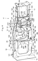
Fig. 1 is a front view showing a wheel-type hydraulic excavator as a construction machine according to the embodiment of the present invention. -
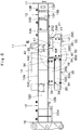
Fig. 2 is a front view showing a lower traveling structure in a state where a drive device side propeller shaft cover, a wheel axle side propeller shaft cover, a step device, a right front wheel and a right rear wheel are removed. -
Fig. 3 is a bottom view showing the lower traveling structure of the wheel-type hydraulic excavator as viewed in the direction of arrows III-III inFig. 2 . -
Fig. 4 is a perspective view showing a single chassis of the lower traveling structure. -
Fig. 5 is a front view showing a chassis in a state where a drive device side propeller shaft cover and a wheel axle side propeller shaft cover are mounted. -
Fig. 6 is a bottom view showing a chassis when seen from a lower surface side in a state where a drive device side propeller shaft cover and a wheel axle side propeller shaft cover are mounted. -
Fig. 7 is an exploded perspective view showing a drive device side propeller shaft cover, a drive device side front bracket, and a drive device side rear bracket. -
Fig. 8 is an exploded perspective view showing a wheel axle side propeller shaft cover, a wheel axle side front bracket, and a wheel axle side rear bracket. -
Fig. 9 is an enlarged view showing an essential part showing a state where a IX part inFig. 5 is enlarged. - Hereinafter, an embodiment of a construction machine according to the present invention will be in detail explained with reference to the accompanying drawings by taking a case in which the construction machine is applied to a wheel-type hydraulic excavator as an example.
- In
Fig. 1 , a wheel-typehydraulic excavator 1 is largely configured by a wheel-typelower traveling structure 2 having left and rightfront wheels 24 and left and rightrear wheels 27 which will be described later, an upper revolvingstructure 4 rotatably mounted on thelower traveling structure 2 through aswing circle 3, and aworking mechanism 5 liftably and tiltably provided on a front side of the upper revolvingstructure 4. Thelower traveling structure 2 and the upper revolvingstructure 4 constitute a vehicle body of the wheel-typehydraulic excavator 1. The wheel-typehydraulic excavator 1 is automotive to a work site by thelower traveling structure 2. Theworking mechanism 5 is configured to include aboom 5A, anarm 5B, and abucket 5C to perform an excavating work of earth and sand at a work site or the like. - The upper revolving
structure 4 for the wheel-typehydraulic excavator 1 has a revolvingframe 6 rotatably mounted on achassis 11 which will be described later through theswing circle 3. Acab 7 defining an operator's room is provided on a left front side of the revolvingframe 6. Acounterweight 8 taking a weight balance with theworking mechanism 5 is provided on a rear end side of the revolvingframe 6. Anengine 9 as a prime mover driving a hydraulic pump (not shown) is provided on a front side of thecounterweight 8. Onboard equipment such as theengine 9, a hydraulic pump or the like are covered with anexterior cover 10. - The
lower traveling structure 2 for the wheel-typehydraulic excavator 1 is configured to include, as shown inFig. 2 to Fig. 6 , achassis 11, afront axle 23, arear axle 26, adrive device 28, apropeller shaft 31, a drive device sidepropeller shaft cover 33, and a wheel axle sidepropeller shaft cover 35 which will be described later. - The
chassis 11 is to be a base of thelower traveling structure 2, and formed as a firm support structure extending in a front-rear direction. Thechassis 11 is configured by arear chassis 12 and afront chassis 13 fixed on a front side of therear chassis 12 through anintermediate plate 13A. Acircle member 14 and arear axle 26 which will be described later are mounted on therear chassis 12, and afront axle 23 which will be described later is mounted on thefront chassis 13. Therear chassis 12 constitutes a box structure surrounded by atop plate 12A extending horizontally in the front-rear direction, alower surface plate 12B faced with thetop plate 12A in the upper-lower direction, a leftside surface plate 12C, and a rightside surface plate 12D. The leftside surface plate 12C and the rightside surface plate 12D are disposed between thetop plate 12A and thelower surface plate 12B and faced with each other in the left-right direction. Thelower surface plate 12B is provided with a rectangular shaped elongated-hole opening 12E extending in the front-rear direction and acircular opening 12F located on a front side of the elongated-hole opening 12E. Left and right wheel axlecase mounting plates lower surface plate 12B of therear chassis 12. Arear axle case 26A which will be described later is mounted on the left and right wheel axlecase mounting plates - A
cylindrical circle member 14 is provided at an intermediate part in the front-rear direction of thetop plate 12A of therear chassis 12. An inner ring of theswing circle 3 is mounted on thecircle member 14, and the revolvingframe 6 of the upper revolvingstructure 4 is mounted on an outer ring of theswing circle 3. Here, thecircle member 14 has high strength. Thus, an inner part of thecircle member 14 in thechassis 11 demonstrates minor deformation and an outer part of thecircle member 14 shows major deformation when thechassis 11 is deformed at the traveling and the like of the wheel-typehydraulic excavator 1. - On the other hand, the
front chassis 13 constitutes a box structure surrounded by atop plate 13B extending horizontally in a front-rear direction, a leftlower surface plate 13C, a rightlower surface plate 13D, a leftside surface plate 13E, and a rightside surface plate 13F. The leftlower surface plate 13C and the rightlower surface plate 13D are disposed with an interval in the left-right direction and faced with thetop plate 13B in the upper-lower direction. The leftside surface plate 13E connects thetop plate 13B and the leftlower surface plate 13C, and the rightside surface plate 13F connects thetop plate 13B and the rightlower surface plate 13D. Suspensionsystem mounting plates 13G (only the rightside surface plate 13F side is shown) are fixed to each of the leftside surface plate 13E and the rightside surface plate 13F. Asuspension system 25 which will be described later is mounted on the suspensionsystem mounting plate 13G. - A rear
attachment mounting plate 15 is provided on a rear end of therear chassis 12. The rearattachment mounting plate 15 is formed as a rectangular shaped plate extending in the left-right direction, on which for example, an earth removingplate device 16 is mounted (seeFig. 1 ). On the other hand, a frontattachment mounting plate 17 is provided at a front end of thefront chassis 13. The frontattachment mounting plate 17 is formed as a rectangular shaped plate extending in the left-right direction, on which for example, abucket holder 17A is mounted (seeFig. 1 ). Thebucket holder 17A holds thebucket 5C of the workingmechanism 5 at the traveling of the wheel-typehydraulic excavator 1. Astep device 18 is provided on each of the leftside surface plate 12C and the rightside surface plate 12D of the rear chassis 12 (only the right side of thestep device 18 is shown inFig. 1 ). Thestep device 18 is disposed between thefront wheel 24 and therear wheel 27 in the state where thestep device 18 protrudes in the left-right direction from the left and rightside surface plates cab 7. - Subsequently, a drive device
side front bracket 19, a drive device siderear bracket 20, a wheel axleside front bracket 21, and a wheel axle siderear bracket 22, which are provided on thelower surface plate 12B of therear chassis 12, will be described. - The drive device
side front bracket 19 is provided on thelower surface plate 12B of therear chassis 12 and constitutes a drive device side bracket together with the drive device siderear bracket 20 which will be described later. As shown inFig. 4 andFig. 7 , the drive deviceside front bracket 19 is configured byupright plates 19A extending in the left-right direction so as to cross over the elongated-hole opening 12E of thelower surface plate 12B and foldedplates 19B folded rearward from an outer peripheral side of anupright plate 19A. Theupright plates 19A are configured by a mountain-shape plate of an intermediate part protruding downward in the left-right direction (length direction). Here, a U-shaped notched propeller shaft insertion part 19A1 is provided at a center part of theupright plates 19A in the left-right direction from an upper side (therear chassis 12 side) to downward. A drive deviceside propeller shaft 31A which will be described later is inserted through the propeller shaft insertion part 19A1. Theupright plate 19A is mounted on the left and rightscrew seat members 19C fixed on thelower surface plate 12B of therear chassis 12 by using a bolt. As a result, the drive deviceside front bracket 19 protrudes from thelower surface plate 12B of therear chassis 12 to downward. - On the other hand, the folded
plate 19B is configured by alower plate 19D parallel to thelower surface plate 12B of therear chassis 12, a leftinclined plate 19E, a rightinclined plate 19F, aleft side plate 19G, and aright side plate 19H. The left inclinedplate 19E extends diagonally upward from a left end of thelower plate 19D toward therear chassis 12, and the rightinclined plate 19F extends diagonally upward from a right end of thelower plate 19D toward therear chassis 12. Theleft side plate 19G extends vertically upward from an upper end of the leftinclined plate 19E toward therear chassis 12, and theright side plate 19H extends vertically upward from an upper end of the rightinclined plate 19F toward therear chassis 12. - The drive device side
rear bracket 20 is located on a rear side of the drive deviceside front bracket 19, and provided on thelower surface plate 12B of therear chassis 12. The drive device siderear bracket 20 is opposite to the drive deviceside front bracket 19 in the front-rear direction. Here, as shown inFig. 6 , a tangent which is perpendicular in the longitudinal direction of thechassis 11 and is tangent to a front end of thecircle member 14 is defined as a front side tangent T1-T1 of thecircle member 14. In addition, a tangent which is perpendicular in the longitudinal direction of thechassis 11 and is tangent to a rear end of thecircle member 14 is defined as a rear side tangent T2-T2 of thecircle member 14. The drive deviceside front bracket 19 and the drive device siderear bracket 20 which constitute a drive device side bracket are provided on thelower surface plate 12B of therear chassis 12, and are disposed within a range that is on a rear side with respect to the front side tangent T1-T1 of thecircle member 14. In addition, the drive device siderear bracket 20 is provided on thelower surface plate 12B of therear chassis 12, and is disposed within a range that is on a front side with respect to the rear side tangent T2-T2 of thecircle member 14. That is, the drive deviceside front bracket 19 and the drive device siderear bracket 20 are disposed within a range between the front side tangent T1-T1 and the rear side tangent T2-T2 (substantially inner side of circle member 14). In this case, the drive device siderear bracket 20 has substantially the same shape as the drive deviceside front bracket 19. The drive device siderear bracket 20 is configured by anupright plate 20A constituted by a mountain-shape plate and a foldedplate 20B folded forward from an outer peripheral side of theupright plate 20A and a propeller shaft insertion part 20A1 is formed at a center part in the left-right direction of theupright plate 20A. - The
upright plate 20A of the drive device siderear bracket 20 is mounted on left and rightscrew seat members 20C fixed on thelower surface plate 12B of therear chassis 12 by using a bolt. As a result, the drive device siderear bracket 20 protrudes from thelower surface plate 12B of therear chassis 12 to downward in the state where the drive device siderear bracket 20 is faced with the drive deviceside front bracket 19 in the front-rear direction. On the other hand, the foldedplate 20B of the drive device siderear bracket 20 is configured by alower plate 20D, a leftinclined plate 20E, a rightinclined plate 20F, aleft side plate 20G, and aright side plate 20H, as in the foldedplate 19B of the drive deviceside front bracket 19. - The wheel axle
side front bracket 21 is located closer to the front side (front chassis 13 side) than the drive deviceside front bracket 19, and provided on thelower surface plate 12B of therear chassis 12. The wheel axleside front bracket 21 constitutes a wheel axle side bracket together with a wheel axle siderear bracket 22 which will be described later. As shown inFig. 4 andFig. 8 , the wheel axleside front bracket 21 is formed by folding a plate having an L-shaped section into a U-shape, and extends in the left-right direction so as to cross over thecircular opening 12F of thelower surface plate 12B. - The wheel axle
side front bracket 21 has aleft side plate 21A and aright side plate 21B extending from thelower surface plate 12B of therear chassis 12 downward and faced with each other in the left-right direction, and alower plate 21C connecting the lower ends of theleft side plate 21A and theright side plate 21B and extending in the left-right direction. Theleft side plate 21A and theright side plate 21B are mounted on left and rightscrew seat members 21D fixed on thelower surface plate 12B of therear chassis 12 by using a bolt. As a result, the wheel axleside front bracket 21 protrudes from thelower surface plate 12B of therear chassis 12 downward. - The wheel axle side
rear bracket 22 is located between the drive deviceside front bracket 19 and the wheel axleside front bracket 21, and provided on thelower surface plate 12B of therear chassis 12. The wheel axle siderear bracket 22 is faced with the wheel axleside front bracket 21 in the front-rear direction. Here, as shown inFig. 6 , the wheel axleside front bracket 21 and the wheel axle siderear bracket 22 which constitute a wheel axle side bracket are provided on thelower surface plate 12B of therear chassis 12, and are disposed within a range that is on a front side with respect to the front side tangent T1-T1 of thecircle member 14. That is, the wheel axleside front bracket 21 and the wheel axle siderear bracket 22 are disposed within a range of an outer side of thecircle member 14. - The wheel axle side
rear bracket 22 is configured to include abracket body 22A constituted by a plate bent having a U-shape, aleft mounting plate 22B and aright mounting plate 22C mounted on thebracket body 22A. Here, a center bearing 32 which will be described later is configured to be mounted on a lower surface 22A1 of thebracket body 22A. Theleft mounting plate 22B and theright mounting plate 22C of the wheel axle siderear bracket 22 are each configured by a plate bent having an L-shape, and mounted on the lower surface 22A1 of thebracket body 22A by using a bolt. Theleft mounting plate 22B has a left side surface 22B1 extending from thebracket body 22A downward, and theright mounting plate 22C has a right side surface 22C1 extending from thebracket body 22A downward. - A
front axle 23 is provided on a lower side of thefront chassis 13, and extends in the left-right direction. Left and rightfront wheels 24 are mounted on both left and right sides of thefront axle 23. As shown inFig. 3 , thefront axle 23 is connected to adrive device 28 through apropeller shaft 31 which will be described later to rotate the left and rightfront wheels 24 by power of theengine 9. Here, thefront axle 23 has afront axle case 23A accommodating a wheel axle body (not shown) and extending in the left-right direction. Adifferential device 23B is provided at an intermediate part of thefront axle case 23A in the left-right direction. A wheel axleside propeller shaft 31B which will be described later is connected to thedifferential device 23B of thefront axle 23, and a rotation of the wheel axleside propeller shaft 31B is transmitted to thefront axle 23 through thedifferential device 23B. - Here, suspension
system mounting plates 13G are provided on each of left and rightside surface plates front chassis 13, and left andright suspension systems 25 are mounted on the suspensionsystem mounting plates 13G (only the right side of thesuspension systems 25 is shown inFig. 2 ). The left andright suspension systems 25 support thefront axle 23 capable of swinging in the upper-lower direction with respect to thefront chassis 13. As a result, thefront axle 23 supporting the left and rightfront wheels 24 can swing (be displaced) in the upper-lower direction depending on the degree of unevenness on the road surface at the traveling of the wheel-typehydraulic excavator 1. - A
rear axle 26 is provided on a lower side of therear chassis 12, and extends in the left-right direction. Left and rightrear wheels 27 are mounted on both left and right sides of therear axle 26. Therear axle 26 has arear axle case 26A accommodating a wheel axle body (not shown) and extending in the left-right direction. Adifferential device 26B is provided at an intermediate part of therear axle case 26A in the left-right direction. Anoutput shaft 30A ofpower transmission device 30 which will be described later is connected to thedifferential device 26B of therear axle 26, and a rotation of theoutput shaft 30A is transmitted to therear axle 26 through thedifferential device 26B, thereby rotating the left and rightrear wheels 27. That is, in this embodiment, theoutput shaft 30A of thepower transmission device 30 serves also as a propeller shaft transmitting output of thedrive device 28 to therear axle 26. Here, both left and right sides of therear axle case 26A are mounted on the left and right wheel axlecase mounting plates rear chassis 12. - The
drive device 28 is mounted on a rear side of therear chassis 12. Thedrive device 28 is configured to include ahydraulic motor 29 andpower transmission device 30 to rotatively drive thefront axle 23 and therear axle 26 by power of theengine 9. Thehydraulic motor 29 is rotatively driven by pressurized oil from a hydraulic pump (not shown) driven by theengine 9. Thepower transmission device 30 has a gear change mechanism reducing rotational output of thehydraulic motor 29 to transmit a rotation outputted to theoutput shaft 30A to thefront axle 23 and therear axle 26. - A
propeller shaft 31 is provided between anoutput shaft 30A of thepower transmission device 30 which constitutes thedrive device 28 and the front axle 23 (differential device 23B) . Thepropeller shaft 31 transmits rotational output of thedrive device 28 to thefront axle 23 as one wheel axle supported to thefront chassis 13 capable of swinging in the upper-lower direction through thesuspension system 25 in thefront axle 23 and therear axle 26. Thepropeller shaft 31 is configured to include a drive deviceside propeller shaft 31A connected to theoutput shaft 30A of thepower transmission device 30, a wheel axleside propeller shaft 31B connected to thedifferential device 23B of thefront axle 23, and a universal joint 31C connecting the drive deviceside propeller shaft 31A and the wheel axleside propeller shaft 31B. - Here, a center bearing 32 is mounted on the
bracket body 22A of the wheel axle siderear bracket 22 provided on a lower surface of therear chassis 12. The center bearing 32 rotatably supports a front side part of the drive deviceside propeller shaft 31A. That is, in the drive deviceside propeller shaft 31A, a rear side part is connected to theoutput shaft 30A of thepower transmission device 30, and a front side part in proximity to the universal joint 31C is rotatably supported by thecenter bearing 32. In this case, the drive deviceside propeller shaft 31A is inserted through the propeller shaft insertion part 19A1 of the drive device side front bracket 19 (upright plate 19A) and the propeller shaft insertion part 20A1 of the drive device side rear bracket 20 (upright plate 20A). Therefore, the drive deviceside propeller shaft 31A is not displaced in the upper-lower direction with respect to therear chassis 12. - On the other hand, in the wheel axle
side propeller shaft 31B, a front side part is connected to thedifferential device 23B of thefront axle 23, and a rear side part is connected to the drive deviceside propeller shaft 31A through the universal joint 31C. As a result, the wheel axleside propeller shaft 31B is configured to smoothly transmit rotation of the drive deviceside propeller shaft 31A through the universal joint 31C. - Therefore, when the
engine 9 is on drive, thehydraulic motor 29 is rotatively driven by pressurized oil discharged from a hydraulic pump (not shown) . A rotation of thehydraulic motor 29 is output to theoutput shaft 30A of thepower transmission device 30 in the state where a rotation of thehydraulic motor 29 is decelerated by thepower transmission device 30. A rotation of theoutput shaft 30A is transmitted to therear axle 26, and also to thefront axle 23 through thepropeller shaft 31. As a result, the left and rightfront wheels 24 and the left and rightrear wheels 27 are rotatively driven, and thereby, enabling the wheel-typehydraulic excavator 1 to travel. - Subsequently, a drive device side
propeller shaft cover 33 and a wheel axle sidepropeller shaft cover 35 adopted in this embodiment will be described. - The drive device side
propeller shaft cover 33 is provided on a lower surface side of therear chassis 12 in the state where the drive deviceside propeller shaft 31A is primarily covered from below. The drive device sidepropeller shaft cover 33, as shown inFig. 6 andFig. 7 , is mounted on the drive deviceside front bracket 19 and the drive device siderear bracket 20 provided on thelower surface plate 12B of therear chassis 12. The drive device sidepropeller shaft cover 33 covers a part other than the front side part of the drive deviceside propeller shaft 31A (part supported on the center bearing 32), and suppresses collision of rocks and the like against the drive deviceside propeller shaft 31A at the traveling of the wheel-typehydraulic excavator 1. - The drive device side
propeller shaft cover 33 is configured by five rectangular shaped plates extending in the front-rear direction bridged between the drive deviceside front bracket 19 and the drive device siderear bracket 20. That is, the drive device sidepropeller shaft cover 33 is configured by abottom surface cover 33A, a leftinclined surface cover 33B, a rightinclined surface cover 33C, a leftside surface cover 33D, and a rightside surface cover 33E. Thebottom surface cover 33A is mounted on thelower plate 19D of the drive deviceside front bracket 19 and thelower plate 20D of the drive device siderear bracket 20. The leftinclined surface cover 33B is mounted on the left inclinedplate 19E of the drive deviceside front bracket 19 and the left inclinedplate 20E of the drive device siderear bracket 20. The rightinclined surface cover 33C is mounted on the right inclinedplate 19F of the drive deviceside front bracket 19 and the rightinclined plate 20F of the drive device siderear bracket 20. The leftside surface cover 33D is mounted on theleft side plate 19G of the drive deviceside front bracket 19 and theleft side plate 20G of the drive device siderear bracket 20. The rightside surface cover 33E is mounted on theright side plate 19H of the drive deviceside front bracket 19 and theright side plate 20H of the drive device siderear bracket 20. The bottom surface cover 33A forms a bottom surface of the drive device sidepropeller shaft cover 33. - The
bottom surface cover 33A, the left and right inclined surface covers 33B, 33C and the left and right side surface covers 33D, 33E of the drive device sidepropeller shaft cover 33 are formed of a rectangular flat plate extending in the front-rear direction, for example, using a steel plate or the like. Therefore, thebottom surface cover 33A, the left and right inclined surface covers 33B, 33C and the left and right side surface covers 33D, 33E are detachably mounted on the drive deviceside front bracket 19 and the drive device siderear bracket 20 using abolt 34. As a result, the drive device sidepropeller shaft cover 33 covers the drive deviceside propeller shaft 31A from below. - As described above, the drive device side
propeller shaft cover 33 according to this embodiment is configured by five plates constituted by thebottom surface cover 33A, the left and right inclined surface covers 33B, 33C, and the left and right side surface covers 33D, 33E. As a result, only deformed covers of thebottom surface cover 33A, the left and right inclined surface covers 33B, 33C, and the left and right side surface covers 33D, 33E can readily be replaced even if, for example, the drive device sidepropeller shaft cover 33 is damaged by collision of rocks and the like. - On the other hand, the wheel axle side
propeller shaft cover 35 is provided on a lower surface side of therear chassis 12 in the state where the wheel axleside propeller shaft 31B, the universal joint 31C and the center bearing 32 are primarily covered from below. As shown inFig. 6 andFig. 8 , the wheel axle sidepropeller shaft cover 35, is mounted on the wheel axleside front bracket 21 and the wheel axle siderear bracket 22 provided on thelower surface plate 12B of therear chassis 12. The wheel axle sidepropeller shaft cover 35 covers a part other than a front side part of the drive deviceside propeller shaft 31A and a front side part of the wheel axleside propeller shaft 31B (part connected to thedifferential device 23B). The wheel axle sidepropeller shaft cover 35 suppresses collision of rocks and the like against the wheel axleside propeller shaft 31B, the universal joint 31C and the center bearing 32 at the traveling of the wheel-typehydraulic excavator 1. - Here, the wheel axle side
propeller shaft cover 35 is configured to include abottom surface cover 36, a connectingplate 37, a leftside surface cover 38, and a rightside surface cover 39. Thebottom surface cover 36 is formed of a rectangular plate extending in the front-rear direction. The bottom surface cover 36 forms a bottom surface of the wheel axle sidepropeller shaft cover 35 together with alower plate 38C of the leftside surface cover 38 and alower plate 39C of the right side surface cover 39 which will be described later. In addition, a rear side part located on the drive device sidepropeller shaft cover 33 side in thebottom surface cover 36 corresponds to anextension part 36A extending toward the drive device sidepropeller shaft cover 33. Theextension part 36A extends closer to a backward than theupright plate 19A of the drive device side front bracket 19 (seeFig. 6 ). - The connecting
plate 37 is formed by folding a plate having an L-shaped section into a U-shape. The connectingplate 37 has aleft side plate 37A, aright side plate 37B, and alower plate 37C connecting the lower ends of the left andright side plates bottom surface cover 36 is mounted on an intermediate part of thelower plate 37C in the left-right direction by using abolt 40. - The left
side surface cover 38 has aside plate 38A, afront plate 38B, and alower plate 38C. Theside plate 38A extends in the vertical direction with respect to thelower surface plate 12B of therear chassis 12, and thefront plate 38B is folded from a front end of theside plate 38A into the right side (the right side surface cover 39 side) . Thelower plate 38C is fixed by means of welding or the like to the lower ends of theside plate 38A and thefront plate 38B, and extends adjacent to thebottom surface cover 36 in the front-rear direction. Thelower plate 38C forms the same plate as thebottom surface cover 36. Here, a rear side part of theside plate 38A is mounted on theleft side plate 37A of the connectingplate 37 by using abolt 40, and a rear side part of thelower plate 38C is mounted on thelower plate 37C of the connectingplate 37 by using abolt 40. A rear side part located on the drive device sidepropeller shaft cover 33 side in thelower plate 38C corresponds to anextension part 38D. Theextension part 38D extends from theside plate 38A toward the drive device sidepropeller shaft cover 33, and extends closer to backward than theupright plate 19A of the drive device side front bracket 19 (seeFig. 6 ). - The right
side surface cover 39 has aside plate 39A, afront plate 39B, and alower plate 39C as in the leftside surface cover 38. Theside plate 39A extends in the vertical direction with respect to thelower surface plate 12B of therear chassis 12, and thefront plate 39B is folded from a front end of theside plate 39A into the left side (the left side surface cover 38 side). Thelower plate 39C is fixed by means of welding or the like to the lower ends of theside plate 39A and thefront plate 39B, and extends adjacent to thebottom surface cover 36 in the front-rear direction. Thelower plate 39C forms the same plate as the bottom surface cover 36 (thebottom surface cover 36 and thelower plate 38C of the left side surface cover 38 overlap thelower plate 39C of the right side surface cover 39 inFig. 9 ). Here, a rear side part of theside plate 39A is mounted to theright side plate 37B of the connectingplate 37 by using abolt 40, and a rear side part of thelower plate 39C is mounted to thelower plate 37C of the connectingplate 37 by using abolt 40. A rear side part located on the drive device sidepropeller shaft cover 33 side in thelower plate 39C corresponds to an extension part39D. Theextension part 39D extends from theside plate 39A toward the drive device sidepropeller shaft cover 33, and extends closer to backward than theupright plate 19A of the drive device side front bracket 19 (seeFig. 6 ). - As described above, the wheel axle side
propeller shaft cover 35 according to this embodiment is formed as a single member by integrating thebottom surface cover 36 and the left and right side surface covers 38, 39 through the connectingplate 37. Therefore, a front side part of thebottom surface cover 36 is mounted to thelower plate 21C of the wheel axleside front bracket 21 by using abolt 41. A front side part of theside plate 38A of the leftside surface cover 38 is mounted to theleft side plate 21A of the wheel axleside front bracket 21 by using abolt 41. An intermediate part in the front-rear direction of theside plate 38A is mounted to theleft mounting plate 22B of the wheel axle siderear bracket 22 by using abolt 41. A front side part of thelower plate 38C of the leftside surface cover 38 is mounted to thelower plate 21C of the wheel axleside front bracket 21 by using abolt 41. In addition, a front side part of theside plate 39A of the rightside surface cover 39 is mounted to theright side plate 21B of the wheel axleside front bracket 21 by using abolt 41. An intermediate part in the front-rear direction of theside plate 39A is mounted to theright mounting plate 22C of the wheel axle siderear bracket 22 by using abolt 41. A front side part of thelower plate 39C of the rightside surface cover 39 is mounted to thelower plate 21C of the wheel axleside front bracket 21 by using abolt 41. - Here, as shown in
Fig. 9 , an interval in the upper-lower direction between a lower surface of thebottom surface cover 36, thelower plate 38C of the leftside surface cover 38, and thelower plate 39C of right side surface cover 39 forming a bottom surface of the wheel axle sidepropeller shaft cover 35, and a lower surface of thelower surface plate 12B which constitutes therear chassis 12 is defined as "A". Moreover, an interval in the upper-lower direction between a lower surface of thebottom surface cover 33A forming a bottom surface of the drive device sidepropeller shaft cover 33, and the lower surface of thelower surface plate 12B which constitutes therear chassis 12 is defined as "B". In this embodiment, the interval A is set larger than the interval B (A>B) . As a result, interference of the wheel axleside propeller shaft 31B with the wheel axle sidepropeller shaft cover 35 can be suppressed even if thefront axle 23 supported by thesuspension system 25 swinging in the upper-lower direction is traced and the wheel axleside propeller shaft 31B is displaced in the upper-lower direction with the universal joint 31C serving as a fulcrum. - Moreover, a rear side part located on the drive device side
propeller shaft cover 33 side in thebottom surface cover 36 which constitutes the bottom surface of the wheel axle sidepropeller shaft cover 35, thelower plate 38C of the leftside surface cover 38, and thelower plate 39C of the rightside surface cover 39 corresponds toextension parts extension parts side plates propeller shaft cover 33. As shown inFig. 6 andFig. 9 , theextension part 36A, theextension part 38D, and theextension part 39D are disposed closer to a lower side than thebottom surface cover 33A of the drive device sidepropeller shaft cover 33, and extend closer to a rear side than theupright plate 19A of the drive device side front bracket 19 (theextension parts extension part 39D inFig. 9 ). As a result, aboundary part 42 between the drive device sidepropeller shaft cover 33 and the wheel axle sidepropeller shaft cover 35 is covered with each of theextension parts extension parts propeller shaft cover 33 and the wheel axle side propeller shaft cover 35 from a gap formed on theboundary part 42 between the drive device sidepropeller shaft cover 33 and the wheel axle sidepropeller shaft cover 35. - The wheel-type
hydraulic excavator 1 according to this embodiment has the above described configuration, and the traveling operation will be explained. - When an onboard operator in a
cab 7 operates anengine 9, ahydraulic motor 29 is rotatively driven by pressurized oil discharged from a hydraulic pump (not shown) . A rotation of thehydraulic motor 29 is output to theoutput shaft 30A of thepower transmission device 30 in the state where a rotation of thehydraulic motor 29 is decelerated by thepower transmission device 30. A rotation of theoutput shaft 30A is transmitted to therear axle 26, and also to thefront axle 23 through thepropeller shaft 31. As a result, the left and rightfront wheels 24 and the left and rightrear wheels 27 are rotatively driven to enable the wheel-typehydraulic excavator 1 to travel. - The
front axle 23 supporting the left and rightfront wheels 24 swings in the upper-lower direction depending on the degree of unevenness on the road surface at the traveling of the wheel-typehydraulic excavator 1. At this time, the wheel axleside propeller shaft 31B connected to thedifferential device 23B of thefront axle 23 is displaced in the upper-lower direction with the universal joint 31C serving as a fulcrum, and can transmit a rotation of a drive deviceside propeller shaft 31A to thefront axle 23. - In this case, according to this embodiment, a propeller shaft cover covering the
propeller shaft 31 is configured by a drive device sidepropeller shaft cover 33 covering the drive deviceside propeller shaft 31A and the wheel axle sidepropeller shaft cover 35 covering the wheel axleside propeller shaft 31B. Here, as shown inFig. 9 , an interval between the lower surface of thebottom surface cover 36, thelower plate 38C of the leftside surface cover 38 and thelower plate 39C of the right side surface cover 39 forming the bottom surface of the wheel axle sidepropeller shaft cover 35, and the lower surface of thelower surface plate 12B which constitutes therear chassis 12 is defined as "A". Moreover, an interval between the lower surface of thebottom surface cover 33A forming the bottom surface of the drive device sidepropeller shaft cover 33 and the lower surface of thelower surface plate 12B which constitutes therear chassis 12 is defined as "B". Therefore, the interval A is set larger than the interval B (A>B). - As a result, interference of the wheel axle
side propeller shaft 31B with the wheel axle sidepropeller shaft cover 35 can assuredly be suppressed even if thefront axle 23 supported by thesuspension system 25 swings in the upper-lower direction and the wheel axleside propeller shaft 31B is displaced in the upper-lower direction with the universal joint 31C serving as a fulcrum. Consequently, the drive deviceside propeller shaft 31A can be protected by the drive device sidepropeller shaft cover 33. Moreover, the wheel axleside propeller shaft 31B, the universal joint 31C, and the center bearing 32 can be protected by the wheel axle sidepropeller shaft cover 35. - In this case, a height from the bottom surface of the drive device side propeller shaft cover 33 (the lower surface of the
bottom surface cover 33A) to the ground can be set larger than a height from the bottom surface of the wheel axle side propeller shaft cover 35 (the lower surface of thebottom surface cover 36, thelower plate 38C of the leftside surface cover 38 and thelower plate 39C of the right side surface cover 39) to the ground. Thus, collision of rocks and the like against the drive device sidepropeller shaft cover 33 can be suppressed, and weight reduction of the drive device sidepropeller shaft cover 33 can be realized. - Moreover, in this embodiment,
extension parts bottom surface cover 36, thelower plate 38C of the leftside surface cover 38, and thelower plate 39C of the right side surface cover 39 which constitute the bottom surface of the wheel axle sidepropeller shaft cover 35. Theextension parts side plates propeller shaft cover 33. Therefore, theextension part 36A, theextension part 38D, andextension part 39D cover theboundary part 42 between the drive device sidepropeller shaft cover 33 and the wheel axle side propeller shaft cover 35 from below. Therefore, it is possible to suppress intrusion of earth and sand and the like into the inside of the drive device sidepropeller shaft cover 33 and the wheel axle sidepropeller shaft cover 35 through a gap formed on theboundary part 42 between the drive device sidepropeller shaft cover 33 and the wheel axle sidepropeller shaft cover 35. As a result, durability of the drive device sidepropeller shaft cover 33 and the wheel axle sidepropeller shaft cover 35 can be improved. - On the other hand, the
rear chassis 12 normally demonstrates small deformation at an inner part of thecircle member 14, and major deformation at an outer part of thecircle member 14 when such deformation occurs to therear chassis 12 at the traveling of the wheel-typehydraulic excavator 1. Thus, the resulting difference in the deformation amount of therear chassis 12 between an inner side and an outer side of thecircle member 14 can readily damage a single propeller shaft cover when, for example, theentire propeller shaft 31 is covered with a single propeller shaft cover. - On the contrary, in this embodiment, a propeller shaft cover covering a
propeller shaft 31 is divided into two halves: a drive device sidepropeller shaft cover 33 covering a drive deviceside propeller shaft 31A and a wheel axle sidepropeller shaft cover 35 covering a wheel axleside propeller shaft 31B. Therefore, the drive device sidepropeller shaft cover 33 is mounted on a drive deviceside front bracket 19 and a drive device siderear bracket 20 disposed between a front side tangent T1-T1 and a rear side tangent T2-T2 of acircle member 14 of arear chassis 12. On the other hand, a wheel axle sidepropeller shaft cover 35 is mounted on a wheel axleside front bracket 21 and a wheel axle siderear bracket 22 disposed on an outer side of thecircle member 14 closer to a front side than the front side tangent T1-T1 of thecircle member 14 of therear chassis 12. Consequently, two halves: the drive device sidepropeller shaft cover 33 and the wheel axle sidepropeller shaft cover 35 are hardly affected by a difference in the deformation amount of therear chassis 12 between an inner side and an outer side of thecircle member 14 even if thechassis 11 causes deformation at the traveling of wheel-typehydraulic excavator 1. Consequently, deformation of the drive device sidepropeller shaft cover 33 and the wheel axle sidepropeller shaft cover 35 can be suppressed to extend the service life, and thepropeller shaft 31, the center bearing 32 and the like can be guarded for a long time. - It should be noted that in the embodiment, the
front axle 23 is supported capable of swinging in the upper-lower direction through thesuspension system 25. Thereby, a case where thepropeller shaft 31 connecting thefront axle 23 and thedrive device 28 is covered with the drive device sidepropeller shaft cover 33 and the wheel axle sidepropeller shaft cover 35 is exemplified. However, the present invention is not limited thereto, and may be configured such that for example, a rear axle is supported capable of swinging in the upper-lower direction through a suspension system to cover a propeller shaft connecting the rear axle and a drive device by a drive device side propeller shaft cover and a wheel axle side propeller shaft cover. -
- 1: Wheel-type hydraulic excavator
- 2: Lower traveling structure
- 3: Swing circle
- 4: Upper revolving structure
- 11: Chassis
- 12: Rear chassis
- 12B: Lower surface plate (Lower surface)
- 14: Circle member
- 19: Drive device side front bracket (Drive device side bracket)
- 20: Drive device side rear bracket (Drive device side bracket)
- 21: Wheel axle side front bracket (Wheel axle side bracket)
- 22: Wheel axle side rear bracket (Wheel axle side bracket)
- 23: Front axle
- 24: Front wheel
- 25: Suspension system
- 26: Rear axle
- 27: Rear wheel
- 28: Drive device
- 31: Propeller shaft
- 31A: Drive device side propeller shaft
- 31B: Wheel axle side propeller shaft
- 31C: Universal joint
- 33: Drive device side propeller shaft cover
- 33A: Bottom surface cover (Bottom surface)
- 35: Wheel axle side propeller shaft cover
- 36: Bottom surface cover (Bottom surface)
- 36A, 38D, 39D: Extension part
- 38: Left side surface cover
- 38C: Lower plate (Bottom surface)
- 39: Right side surface cover
- 39C: Lower plate (Bottom surface)
- 42: Boundary part
Claims (5)
- A construction machine comprising:an automotive lower traveling structure having left and right front wheels and left and right rear wheels; andan upper revolving structure rotatably mounted on the lower traveling structure through a swing circle and in which a prime mover is provided;the lower traveling structure being configured to include:a chassis constituting a support structure;a front axle provided on a front side of the chassis and on which the left and right front wheels are mounted;a rear axle provided on a rear side of the chassis and on which the left and right rear wheels are mounted;a drive device mounted on the chassis and rotatively driving the front axle and the rear axle by power of the prime mover; anda propeller shaft transmitting output of the drive device to the front axle and the rear axle, whereina suspension system is provided between the chassis and a wheel axle which is any one of the front axle and the rear axle, and supports capable of swinging the wheel axle in a upper-lower direction,the propeller shaft comprising:a drive device side propeller shaft connected to the drive device;a wheel axle side propeller shaft connected to the one of the front axle and the rear axle supported by the suspension system; anda universal joint connecting the drive device side propeller shaft and the wheel axle side propeller shaft,characterized in that:
the lower traveling structure comprises:a drive device side propeller shaft cover provided on a lower surface of the chassis and covering the drive device side propeller shaft from below; anda wheel axle side propeller shaft cover provided on the lower surface of the chassis and covering the wheel axle side propeller shaft from below, whereinan interval in the upper-lower direction between a bottom surface of the wheel axle side propeller shaft cover and the lower surface of the chassis is set larger than an interval in the upper-lower direction between a bottom surface of the drive device side propeller shaft cover and the lower surface of the chassis. - The construction machine according to claim 1, wherein
an extension part extending toward the drive device side propeller shaft cover is provided at a part located on the drive device side propeller shaft cover side in the bottom surface of the wheel axle side propeller shaft cover; and
a boundary part between the drive device side propeller shaft cover and the wheel axle side propeller shaft cover is covered from below by the extension part. - The construction machine according to claim 1, wherein a cylindrical circle member on which the swing circle is mounted is provided on an upper surface of the chassis;
a drive device side bracket mounting the drive device side propeller shaft cover and a wheel axle side bracket mounting the wheel axle side propeller shaft cover are provided on the lower surface of the chassis;
the drive device side bracket is provided on the lower surface of the chassis, and is disposed within a range that is on a rear side with respect to a front side tangent which is perpendicular in the longitudinal direction of the chassis and is tangent to a front end of the circle member; and
the wheel axle side bracket is provided on the lower surface of the chassis, and is disposed within a range that is on a front side with respect to the front side tangent of the circle member. - The construction machine according to claim 3, wherein
the drive device side bracket comprises:a drive device side front bracket; anda drive device side rear bracket that is closer to a rear side than the drive device side front bracket, whereinthe drive device side rear bracket is provided on the lower surface of the chassis, and is disposed within a range that is on a front side with respect to a rear side tangent which is perpendicular in the longitudinal direction of the chassis and is tangent to a rear end of the circle member. - The construction machine according to claim 1, wherein
the drive device side propeller shaft cover covers a part other than a front side part of the drive device side propeller shaft, wherein
the wheel axle side propeller shaft cover covers a part other than the front side part of the drive device side propeller shaft and a front side part of the wheel axle side propeller shaft.
Applications Claiming Priority (2)
| Application Number | Priority Date | Filing Date | Title |
|---|---|---|---|
| JP2017166753A JP6746544B2 (en) | 2017-08-31 | 2017-08-31 | Construction machinery |
| PCT/JP2018/031189 WO2019044658A1 (en) | 2017-08-31 | 2018-08-23 | Construction machinery |
Publications (3)
| Publication Number | Publication Date |
|---|---|
| EP3578719A1 true EP3578719A1 (en) | 2019-12-11 |
| EP3578719A4 EP3578719A4 (en) | 2021-01-13 |
| EP3578719B1 EP3578719B1 (en) | 2023-08-16 |
Family
ID=65525375
Family Applications (1)
| Application Number | Title | Priority Date | Filing Date |
|---|---|---|---|
| EP18849852.1A Active EP3578719B1 (en) | 2017-08-31 | 2018-08-23 | Construction machinery |
Country Status (4)
| Country | Link |
|---|---|
| EP (1) | EP3578719B1 (en) |
| JP (1) | JP6746544B2 (en) |
| CN (1) | CN110337514B (en) |
| WO (1) | WO2019044658A1 (en) |
Family Cites Families (21)
| Publication number | Priority date | Publication date | Assignee | Title |
|---|---|---|---|---|
| JPS606825B2 (en) * | 1976-10-29 | 1985-02-20 | 株式会社小松製作所 | Birefringent vehicle body |
| JPS6095233U (en) * | 1983-12-06 | 1985-06-28 | 日立建機株式会社 | Lubrication structure of vertical propeller shaft |
| JP2504343Y2 (en) * | 1990-08-24 | 1996-07-10 | 東洋運搬機株式会社 | Cybello loader |
| JPH06173297A (en) * | 1992-12-04 | 1994-06-21 | Komatsu Ltd | Wheeled construction machine chassis structure |
| US6158535A (en) * | 1997-04-01 | 2000-12-12 | Manitowoc Crane Group, Inc. | Mechanical track drive |
| JP2000159481A (en) * | 1998-04-23 | 2000-06-13 | Yutani Heavy Ind Ltd | Self-propelled crane |
| JP4055309B2 (en) * | 1999-03-31 | 2008-03-05 | 日産自動車株式会社 | Automotive power transmission structure |
| JP2005054968A (en) * | 2003-08-07 | 2005-03-03 | Kubota Corp | Driving transmission structure of work vehicle |
| WO2007126348A1 (en) * | 2006-04-28 | 2007-11-08 | Volvo Construction Equipment Ab | A wheel brake for a vehicle and a vehicle comprising the wheel brake |
| JP2008208903A (en) | 2007-02-26 | 2008-09-11 | Nsk Ltd | Bearing structure |
| JP2008273267A (en) | 2007-04-25 | 2008-11-13 | Showa Corp | Propeller shaft for automobile |
| US8602153B2 (en) * | 2007-08-06 | 2013-12-10 | Extendquip Llc | Extendable frame work vehicle |
| JP5016421B2 (en) * | 2007-09-10 | 2012-09-05 | 株式会社クボタ | Work vehicle transmission structure |
| EP2036802B1 (en) * | 2007-09-11 | 2011-08-03 | CNH Italia S.p.A. | Vehicle, in particular a farm tractor, and relative assembly method |
| JP4977063B2 (en) * | 2008-03-10 | 2012-07-18 | 株式会社クボタ | Tractor |
| JP5401251B2 (en) * | 2009-10-07 | 2014-01-29 | 日立建機株式会社 | Construction machinery |
| JP2012071671A (en) * | 2010-09-28 | 2012-04-12 | Hitachi Constr Mach Co Ltd | Wheel type traveling body for construction vehicle |
| CN202298738U (en) * | 2011-09-28 | 2012-07-04 | 郑明法 | Transmission protection device of forklift |
| JP2014097720A (en) * | 2012-11-14 | 2014-05-29 | Suzuki Motor Corp | Propeller shaft falling prevention structure of vehicle |
| JP5887288B2 (en) * | 2013-02-04 | 2016-03-16 | 日立建機株式会社 | Wheel loader |
| JP6076189B2 (en) * | 2013-04-26 | 2017-02-08 | 株式会社小松製作所 | Wheel loader |
-
2017
- 2017-08-31 JP JP2017166753A patent/JP6746544B2/en active Active
-
2018
- 2018-08-23 CN CN201880014349.7A patent/CN110337514B/en active Active
- 2018-08-23 EP EP18849852.1A patent/EP3578719B1/en active Active
- 2018-08-23 WO PCT/JP2018/031189 patent/WO2019044658A1/en not_active Ceased
Also Published As
| Publication number | Publication date |
|---|---|
| CN110337514B (en) | 2021-08-06 |
| WO2019044658A1 (en) | 2019-03-07 |
| EP3578719B1 (en) | 2023-08-16 |
| CN110337514A (en) | 2019-10-15 |
| EP3578719A4 (en) | 2021-01-13 |
| JP6746544B2 (en) | 2020-08-26 |
| JP2019044408A (en) | 2019-03-22 |
Similar Documents
| Publication | Publication Date | Title |
|---|---|---|
| CN101253071B (en) | Frame structure for construction machine | |
| EP2610406A1 (en) | Construction machine | |
| EP1479832B1 (en) | Crawler frame for a construction machine | |
| JP2003056009A (en) | Swing-out type counterweight construction for motor vehicle | |
| EP3578719B1 (en) | Construction machinery | |
| JP4617096B2 (en) | Construction machinery | |
| EP4194616B1 (en) | Cab support structure and construction machine | |
| JP2001171977A (en) | Wheel type construction machine | |
| JP3695301B2 (en) | Small swing excavator at the rear end | |
| JP5343096B2 (en) | Construction machinery | |
| KR102872866B1 (en) | work machine | |
| EP1997965A1 (en) | Excavation machine | |
| JP4798985B2 (en) | Swivel work machine | |
| WO2022064920A1 (en) | Wheeled construction machine | |
| JP2005350948A (en) | Hydraulic excavator protecting device | |
| JP7781819B2 (en) | Construction machinery boom support base and construction machinery | |
| JP5202581B2 (en) | Swivel work machine | |
| CN101115884A (en) | Work vehicle | |
| JP2005170212A (en) | Construction machine | |
| JP2004196059A (en) | Chassis structure of wheel type construction machine | |
| JP2024118909A (en) | Swing frame for construction machinery | |
| JP2025074112A (en) | Work Machine | |
| JP2024114247A (en) | Arm Support Structure | |
| JP2000190742A (en) | Rotary construction machine | |
| JP2000264267A (en) | Track laying vehicle |
Legal Events
| Date | Code | Title | Description |
|---|---|---|---|
| STAA | Information on the status of an ep patent application or granted ep patent |
Free format text: STATUS: THE INTERNATIONAL PUBLICATION HAS BEEN MADE |
|
| PUAI | Public reference made under article 153(3) epc to a published international application that has entered the european phase |
Free format text: ORIGINAL CODE: 0009012 |
|
| STAA | Information on the status of an ep patent application or granted ep patent |
Free format text: STATUS: REQUEST FOR EXAMINATION WAS MADE |
|
| 17P | Request for examination filed |
Effective date: 20190902 |
|
| AK | Designated contracting states |
Kind code of ref document: A1 Designated state(s): AL AT BE BG CH CY CZ DE DK EE ES FI FR GB GR HR HU IE IS IT LI LT LU LV MC MK MT NL NO PL PT RO RS SE SI SK SM TR |
|
| AX | Request for extension of the european patent |
Extension state: BA ME |
|
| DAV | Request for validation of the european patent (deleted) | ||
| DAX | Request for extension of the european patent (deleted) | ||
| A4 | Supplementary search report drawn up and despatched |
Effective date: 20201211 |
|
| RIC1 | Information provided on ipc code assigned before grant |
Ipc: E02F 9/02 20060101AFI20201207BHEP Ipc: E02F 9/12 20060101ALI20201207BHEP Ipc: B60K 17/22 20060101ALI20201207BHEP |
|
| GRAP | Despatch of communication of intention to grant a patent |
Free format text: ORIGINAL CODE: EPIDOSNIGR1 |
|
| STAA | Information on the status of an ep patent application or granted ep patent |
Free format text: STATUS: GRANT OF PATENT IS INTENDED |
|
| INTG | Intention to grant announced |
Effective date: 20230413 |
|
| GRAS | Grant fee paid |
Free format text: ORIGINAL CODE: EPIDOSNIGR3 |
|
| GRAA | (expected) grant |
Free format text: ORIGINAL CODE: 0009210 |
|
| STAA | Information on the status of an ep patent application or granted ep patent |
Free format text: STATUS: THE PATENT HAS BEEN GRANTED |
|
| AK | Designated contracting states |
Kind code of ref document: B1 Designated state(s): AL AT BE BG CH CY CZ DE DK EE ES FI FR GB GR HR HU IE IS IT LI LT LU LV MC MK MT NL NO PL PT RO RS SE SI SK SM TR |
|
| REG | Reference to a national code |
Ref country code: CH Ref legal event code: EP Ref country code: DE Ref legal event code: R096 Ref document number: 602018055636 Country of ref document: DE |
|
| REG | Reference to a national code |
Ref country code: IE Ref legal event code: FG4D |
|
| REG | Reference to a national code |
Ref country code: LT Ref legal event code: MG9D |
|
| REG | Reference to a national code |
Ref country code: NL Ref legal event code: MP Effective date: 20230816 |
|
| REG | Reference to a national code |
Ref country code: AT Ref legal event code: MK05 Ref document number: 1600187 Country of ref document: AT Kind code of ref document: T Effective date: 20230816 |
|
| PG25 | Lapsed in a contracting state [announced via postgrant information from national office to epo] |
Ref country code: GR Free format text: LAPSE BECAUSE OF FAILURE TO SUBMIT A TRANSLATION OF THE DESCRIPTION OR TO PAY THE FEE WITHIN THE PRESCRIBED TIME-LIMIT Effective date: 20231117 |
|
| PG25 | Lapsed in a contracting state [announced via postgrant information from national office to epo] |
Ref country code: IS Free format text: LAPSE BECAUSE OF FAILURE TO SUBMIT A TRANSLATION OF THE DESCRIPTION OR TO PAY THE FEE WITHIN THE PRESCRIBED TIME-LIMIT Effective date: 20231216 |
|
| PG25 | Lapsed in a contracting state [announced via postgrant information from national office to epo] |
Ref country code: SE Free format text: LAPSE BECAUSE OF FAILURE TO SUBMIT A TRANSLATION OF THE DESCRIPTION OR TO PAY THE FEE WITHIN THE PRESCRIBED TIME-LIMIT Effective date: 20230816 Ref country code: RS Free format text: LAPSE BECAUSE OF FAILURE TO SUBMIT A TRANSLATION OF THE DESCRIPTION OR TO PAY THE FEE WITHIN THE PRESCRIBED TIME-LIMIT Effective date: 20230816 Ref country code: PT Free format text: LAPSE BECAUSE OF FAILURE TO SUBMIT A TRANSLATION OF THE DESCRIPTION OR TO PAY THE FEE WITHIN THE PRESCRIBED TIME-LIMIT Effective date: 20231218 Ref country code: NO Free format text: LAPSE BECAUSE OF FAILURE TO SUBMIT A TRANSLATION OF THE DESCRIPTION OR TO PAY THE FEE WITHIN THE PRESCRIBED TIME-LIMIT Effective date: 20231116 Ref country code: NL Free format text: LAPSE BECAUSE OF FAILURE TO SUBMIT A TRANSLATION OF THE DESCRIPTION OR TO PAY THE FEE WITHIN THE PRESCRIBED TIME-LIMIT Effective date: 20230816 Ref country code: LV Free format text: LAPSE BECAUSE OF FAILURE TO SUBMIT A TRANSLATION OF THE DESCRIPTION OR TO PAY THE FEE WITHIN THE PRESCRIBED TIME-LIMIT Effective date: 20230816 Ref country code: LT Free format text: LAPSE BECAUSE OF FAILURE TO SUBMIT A TRANSLATION OF THE DESCRIPTION OR TO PAY THE FEE WITHIN THE PRESCRIBED TIME-LIMIT Effective date: 20230816 Ref country code: IS Free format text: LAPSE BECAUSE OF FAILURE TO SUBMIT A TRANSLATION OF THE DESCRIPTION OR TO PAY THE FEE WITHIN THE PRESCRIBED TIME-LIMIT Effective date: 20231216 Ref country code: HR Free format text: LAPSE BECAUSE OF FAILURE TO SUBMIT A TRANSLATION OF THE DESCRIPTION OR TO PAY THE FEE WITHIN THE PRESCRIBED TIME-LIMIT Effective date: 20230816 Ref country code: GR Free format text: LAPSE BECAUSE OF FAILURE TO SUBMIT A TRANSLATION OF THE DESCRIPTION OR TO PAY THE FEE WITHIN THE PRESCRIBED TIME-LIMIT Effective date: 20231117 Ref country code: FI Free format text: LAPSE BECAUSE OF FAILURE TO SUBMIT A TRANSLATION OF THE DESCRIPTION OR TO PAY THE FEE WITHIN THE PRESCRIBED TIME-LIMIT Effective date: 20230816 Ref country code: AT Free format text: LAPSE BECAUSE OF FAILURE TO SUBMIT A TRANSLATION OF THE DESCRIPTION OR TO PAY THE FEE WITHIN THE PRESCRIBED TIME-LIMIT Effective date: 20230816 |
|
| PG25 | Lapsed in a contracting state [announced via postgrant information from national office to epo] |
Ref country code: PL Free format text: LAPSE BECAUSE OF FAILURE TO SUBMIT A TRANSLATION OF THE DESCRIPTION OR TO PAY THE FEE WITHIN THE PRESCRIBED TIME-LIMIT Effective date: 20230816 |
|
| REG | Reference to a national code |
Ref country code: CH Ref legal event code: PL |
|
| PG25 | Lapsed in a contracting state [announced via postgrant information from national office to epo] |
Ref country code: LU Free format text: LAPSE BECAUSE OF NON-PAYMENT OF DUE FEES Effective date: 20230823 |
|
| PG25 | Lapsed in a contracting state [announced via postgrant information from national office to epo] |
Ref country code: ES Free format text: LAPSE BECAUSE OF FAILURE TO SUBMIT A TRANSLATION OF THE DESCRIPTION OR TO PAY THE FEE WITHIN THE PRESCRIBED TIME-LIMIT Effective date: 20230816 |
|
| PG25 | Lapsed in a contracting state [announced via postgrant information from national office to epo] |
Ref country code: SM Free format text: LAPSE BECAUSE OF FAILURE TO SUBMIT A TRANSLATION OF THE DESCRIPTION OR TO PAY THE FEE WITHIN THE PRESCRIBED TIME-LIMIT Effective date: 20230816 Ref country code: RO Free format text: LAPSE BECAUSE OF FAILURE TO SUBMIT A TRANSLATION OF THE DESCRIPTION OR TO PAY THE FEE WITHIN THE PRESCRIBED TIME-LIMIT Effective date: 20230816 Ref country code: LU Free format text: LAPSE BECAUSE OF NON-PAYMENT OF DUE FEES Effective date: 20230823 Ref country code: ES Free format text: LAPSE BECAUSE OF FAILURE TO SUBMIT A TRANSLATION OF THE DESCRIPTION OR TO PAY THE FEE WITHIN THE PRESCRIBED TIME-LIMIT Effective date: 20230816 Ref country code: EE Free format text: LAPSE BECAUSE OF FAILURE TO SUBMIT A TRANSLATION OF THE DESCRIPTION OR TO PAY THE FEE WITHIN THE PRESCRIBED TIME-LIMIT Effective date: 20230816 Ref country code: DK Free format text: LAPSE BECAUSE OF FAILURE TO SUBMIT A TRANSLATION OF THE DESCRIPTION OR TO PAY THE FEE WITHIN THE PRESCRIBED TIME-LIMIT Effective date: 20230816 Ref country code: CZ Free format text: LAPSE BECAUSE OF FAILURE TO SUBMIT A TRANSLATION OF THE DESCRIPTION OR TO PAY THE FEE WITHIN THE PRESCRIBED TIME-LIMIT Effective date: 20230816 Ref country code: CH Free format text: LAPSE BECAUSE OF NON-PAYMENT OF DUE FEES Effective date: 20230831 Ref country code: SK Free format text: LAPSE BECAUSE OF FAILURE TO SUBMIT A TRANSLATION OF THE DESCRIPTION OR TO PAY THE FEE WITHIN THE PRESCRIBED TIME-LIMIT Effective date: 20230816 |
|
| REG | Reference to a national code |
Ref country code: BE Ref legal event code: MM Effective date: 20230831 |
|
| REG | Reference to a national code |
Ref country code: DE Ref legal event code: R097 Ref document number: 602018055636 Country of ref document: DE |
|
| REG | Reference to a national code |
Ref country code: IE Ref legal event code: MM4A |
|
| PG25 | Lapsed in a contracting state [announced via postgrant information from national office to epo] |
Ref country code: MC Free format text: LAPSE BECAUSE OF FAILURE TO SUBMIT A TRANSLATION OF THE DESCRIPTION OR TO PAY THE FEE WITHIN THE PRESCRIBED TIME-LIMIT Effective date: 20230816 |
|
| PLBE | No opposition filed within time limit |
Free format text: ORIGINAL CODE: 0009261 |
|
| STAA | Information on the status of an ep patent application or granted ep patent |
Free format text: STATUS: NO OPPOSITION FILED WITHIN TIME LIMIT |
|
| PG25 | Lapsed in a contracting state [announced via postgrant information from national office to epo] |
Ref country code: IE Free format text: LAPSE BECAUSE OF NON-PAYMENT OF DUE FEES Effective date: 20230823 |
|
| 26N | No opposition filed |
Effective date: 20240517 |
|
| PG25 | Lapsed in a contracting state [announced via postgrant information from national office to epo] |
Ref country code: IT Free format text: LAPSE BECAUSE OF FAILURE TO SUBMIT A TRANSLATION OF THE DESCRIPTION OR TO PAY THE FEE WITHIN THE PRESCRIBED TIME-LIMIT Effective date: 20230816 Ref country code: IE Free format text: LAPSE BECAUSE OF NON-PAYMENT OF DUE FEES Effective date: 20230823 Ref country code: FR Free format text: LAPSE BECAUSE OF NON-PAYMENT OF DUE FEES Effective date: 20231016 Ref country code: SI Free format text: LAPSE BECAUSE OF FAILURE TO SUBMIT A TRANSLATION OF THE DESCRIPTION OR TO PAY THE FEE WITHIN THE PRESCRIBED TIME-LIMIT Effective date: 20230816 |
|
| PG25 | Lapsed in a contracting state [announced via postgrant information from national office to epo] |
Ref country code: BE Free format text: LAPSE BECAUSE OF NON-PAYMENT OF DUE FEES Effective date: 20230831 |
|
| PG25 | Lapsed in a contracting state [announced via postgrant information from national office to epo] |
Ref country code: BG Free format text: LAPSE BECAUSE OF FAILURE TO SUBMIT A TRANSLATION OF THE DESCRIPTION OR TO PAY THE FEE WITHIN THE PRESCRIBED TIME-LIMIT Effective date: 20230816 |
|
| PG25 | Lapsed in a contracting state [announced via postgrant information from national office to epo] |
Ref country code: BG Free format text: LAPSE BECAUSE OF FAILURE TO SUBMIT A TRANSLATION OF THE DESCRIPTION OR TO PAY THE FEE WITHIN THE PRESCRIBED TIME-LIMIT Effective date: 20230816 |
|
| PG25 | Lapsed in a contracting state [announced via postgrant information from national office to epo] |
Ref country code: CY Free format text: LAPSE BECAUSE OF FAILURE TO SUBMIT A TRANSLATION OF THE DESCRIPTION OR TO PAY THE FEE WITHIN THE PRESCRIBED TIME-LIMIT; INVALID AB INITIO Effective date: 20180823 |
|
| PG25 | Lapsed in a contracting state [announced via postgrant information from national office to epo] |
Ref country code: HU Free format text: LAPSE BECAUSE OF FAILURE TO SUBMIT A TRANSLATION OF THE DESCRIPTION OR TO PAY THE FEE WITHIN THE PRESCRIBED TIME-LIMIT; INVALID AB INITIO Effective date: 20180823 |
|
| PGFP | Annual fee paid to national office [announced via postgrant information from national office to epo] |
Ref country code: DE Payment date: 20250702 Year of fee payment: 8 |
|
| PGFP | Annual fee paid to national office [announced via postgrant information from national office to epo] |
Ref country code: GB Payment date: 20250703 Year of fee payment: 8 |
|
| PG25 | Lapsed in a contracting state [announced via postgrant information from national office to epo] |
Ref country code: TR Free format text: LAPSE BECAUSE OF FAILURE TO SUBMIT A TRANSLATION OF THE DESCRIPTION OR TO PAY THE FEE WITHIN THE PRESCRIBED TIME-LIMIT Effective date: 20230816 |