EP3578632A1 - Apparatus for the production of sparkling wines - Google Patents
Apparatus for the production of sparkling wines Download PDFInfo
- Publication number
- EP3578632A1 EP3578632A1 EP19177605.3A EP19177605A EP3578632A1 EP 3578632 A1 EP3578632 A1 EP 3578632A1 EP 19177605 A EP19177605 A EP 19177605A EP 3578632 A1 EP3578632 A1 EP 3578632A1
- Authority
- EP
- European Patent Office
- Prior art keywords
- container
- membrane
- spherical
- thickness
- elastomeric material
- Prior art date
- Legal status (The legal status is an assumption and is not a legal conclusion. Google has not performed a legal analysis and makes no representation as to the accuracy of the status listed.)
- Withdrawn
Links
- 238000004519 manufacturing process Methods 0.000 title claims abstract description 13
- 235000015040 sparkling wine Nutrition 0.000 title claims abstract description 11
- 239000012528 membrane Substances 0.000 claims description 32
- 239000013536 elastomeric material Substances 0.000 claims description 16
- LYCAIKOWRPUZTN-UHFFFAOYSA-N Ethylene glycol Chemical compound OCCO LYCAIKOWRPUZTN-UHFFFAOYSA-N 0.000 claims description 9
- 229920002943 EPDM rubber Polymers 0.000 claims description 6
- 229910000831 Steel Inorganic materials 0.000 claims description 6
- 239000010959 steel Substances 0.000 claims description 6
- 229910001220 stainless steel Inorganic materials 0.000 claims description 4
- 239000010935 stainless steel Substances 0.000 claims description 4
- VGGSQFUCUMXWEO-UHFFFAOYSA-N Ethene Chemical compound C=C VGGSQFUCUMXWEO-UHFFFAOYSA-N 0.000 claims description 3
- 239000005977 Ethylene Substances 0.000 claims description 3
- 150000001993 dienes Chemical class 0.000 claims description 3
- 239000000463 material Substances 0.000 claims description 3
- QQONPFPTGQHPMA-UHFFFAOYSA-N propylene Natural products CC=C QQONPFPTGQHPMA-UHFFFAOYSA-N 0.000 claims description 3
- 125000004805 propylene group Chemical group [H]C([H])([H])C([H])([*:1])C([H])([H])[*:2] 0.000 claims description 3
- 229920001897 terpolymer Polymers 0.000 claims description 3
- 239000013013 elastic material Substances 0.000 claims description 2
- 238000005304 joining Methods 0.000 claims description 2
- 230000001747 exhibiting effect Effects 0.000 claims 1
- CURLTUGMZLYLDI-UHFFFAOYSA-N Carbon dioxide Chemical compound O=C=O CURLTUGMZLYLDI-UHFFFAOYSA-N 0.000 description 8
- 229910002092 carbon dioxide Inorganic materials 0.000 description 6
- 238000000855 fermentation Methods 0.000 description 6
- 230000004151 fermentation Effects 0.000 description 6
- 235000014101 wine Nutrition 0.000 description 6
- 238000009826 distribution Methods 0.000 description 5
- 238000000034 method Methods 0.000 description 5
- 238000003466 welding Methods 0.000 description 5
- LFQSCWFLJHTTHZ-UHFFFAOYSA-N Ethanol Chemical compound CCO LFQSCWFLJHTTHZ-UHFFFAOYSA-N 0.000 description 4
- 238000013019 agitation Methods 0.000 description 3
- 235000013305 food Nutrition 0.000 description 3
- 239000011810 insulating material Substances 0.000 description 3
- 240000004808 Saccharomyces cerevisiae Species 0.000 description 2
- 239000002253 acid Substances 0.000 description 2
- 150000007513 acids Chemical class 0.000 description 2
- 239000007864 aqueous solution Substances 0.000 description 2
- 239000001569 carbon dioxide Substances 0.000 description 2
- 238000005516 engineering process Methods 0.000 description 2
- 235000019441 ethanol Nutrition 0.000 description 2
- 239000007789 gas Substances 0.000 description 2
- 230000035699 permeability Effects 0.000 description 2
- 239000000243 solution Substances 0.000 description 2
- 239000000126 substance Substances 0.000 description 2
- 238000005406 washing Methods 0.000 description 2
- XLYOFNOQVPJJNP-UHFFFAOYSA-N water Substances O XLYOFNOQVPJJNP-UHFFFAOYSA-N 0.000 description 2
- 239000008346 aqueous phase Substances 0.000 description 1
- 230000015572 biosynthetic process Effects 0.000 description 1
- 238000010276 construction Methods 0.000 description 1
- 230000000694 effects Effects 0.000 description 1
- 230000007613 environmental effect Effects 0.000 description 1
- 238000009413 insulation Methods 0.000 description 1
- 229920002635 polyurethane Polymers 0.000 description 1
- 239000004814 polyurethane Substances 0.000 description 1
- 238000003756 stirring Methods 0.000 description 1
- 235000000346 sugar Nutrition 0.000 description 1
- 150000008163 sugars Chemical class 0.000 description 1
- 238000003786 synthesis reaction Methods 0.000 description 1
Images



Classifications
-
- C—CHEMISTRY; METALLURGY
- C12—BIOCHEMISTRY; BEER; SPIRITS; WINE; VINEGAR; MICROBIOLOGY; ENZYMOLOGY; MUTATION OR GENETIC ENGINEERING
- C12G—WINE; PREPARATION THEREOF; ALCOHOLIC BEVERAGES; PREPARATION OF ALCOHOLIC BEVERAGES NOT PROVIDED FOR IN SUBCLASSES C12C OR C12H
- C12G1/00—Preparation of wine or sparkling wine
- C12G1/06—Preparation of sparkling wine; Impregnation of wine with carbon dioxide
-
- C—CHEMISTRY; METALLURGY
- C12—BIOCHEMISTRY; BEER; SPIRITS; WINE; VINEGAR; MICROBIOLOGY; ENZYMOLOGY; MUTATION OR GENETIC ENGINEERING
- C12C—BEER; PREPARATION OF BEER BY FERMENTATION; PREPARATION OF MALT FOR MAKING BEER; PREPARATION OF HOPS FOR MAKING BEER
- C12C11/00—Fermentation processes for beer
- C12C11/003—Fermentation of beerwort
- C12C11/006—Fermentation tanks therefor
Definitions
- the present invention relates to the production of wine, and particularly it relates to an apparatus for the production of sparkling wines.
- Sparkling wines are generally obtained by second fermentation of a wine, or an assembly of wines, with the addition of appropriate amounts of sugars and yeasts, in a pressurized environment.
- the two main operating lines follow the so-called classic method, or champenois, in which the second fermentation is conducted directly in the bottle, or the Martinotti-Charmat method, in which the second fermentation is carried out on large quantities of wine in special containers, the so-called autoclaves.
- the technologies that have developed over time have generally concerned the chemical aspects, that is the selection and production of yeasts, and of aid to production, that is the operations of handling of the bottles such as rotation and inclination variation
- the impact of technologies has been characterized by the development of control systems for the environmental conditions inside the autoclave, the agitation, and the development of the structure of the autoclave itself, whose manufacturing technique has gone hand in hand with that of similar equipment used in the chemical and pharmaceutical industry.
- the aim of the present invention is therefore to provide an apparatus for the production of sparkling wines which spontaneously allows a better and more homogeneous distribution of the pressure inside it, and thus favors the correct balance between carbon dioxide and the aqueous phase in reduced times.
- Object of the present invention is therefore an apparatus for the production of sparkling wines comprising a pressurized container adapted to withstand a pressure of at least 6 bar, and preferably of at least 8 bar, provided with a suitable access provided with autoclave closure; said container is substantially spherical in shape.
- said spherical container is made of stainless steel, provided with an inner insulation layer and provided with heat-exchanging means.
- the wall of this container has a thickness of between 0.2 mm and 1.00 mm, and preferably between 0.3 mm and 0.7 mm, more preferably it has a thickness of 0.5 mm.
- the container is preferably made by joining a plurality of spherical spindles, with two spherical caps arranged at the diametral ends of said spindles.
- the various parts of the container wall are assembled by welding, such as TIG welding.
- the container has a capacity in the order of 15-40 hi, and preferably in the order of 25 hi; against this capacity the container has a radius between about 0.7 m and about 1.0 m.
- the insulating layer has a thickness that can range from 2.0 mm to 15.0 mm, depending on the insulating material used and the design needs of the container; in particular it is considered advantageous to insulate with a layer in the order of 10.0 mm of expanded polyurethane, typically with a closed cell, which can be suitably surface treated to be adapted to the food requirements, or it can be enclosed in a gap with a further spherical wall in steel.
- said spherical container is a membrane of elastomeric material, with a wall thickness in the range of 1.0 to 4.0 mm, and preferably from 1.5 mm to 3.0 mm, more preferably of thickness in the order of 2.0 mm.
- the elastomeric material is selected from those which exhibit a tensile strength between 7 and 21 MPa, an elongation between 100% and 400%, and preferably 200%, and a good elastic yield.
- the elastomeric material must also be equipped with a good thermal inertia and a high resistance to water, to acids diluted in aqueous solution, to ethyl alcohol, and a low permeability to gases.
- the elastomeric material will be an EPDM (ethylene propylene diene monomer), i.e. a terpolymer of ethylene and propylene grafted with a non-conjugated diene.
- EPDM ethylene propylene diene monomer
- the container will have an initial volume equal to about 50% of the volume of a similar rigid-walled container, and will reach a volume, in the working regime, in the order of 15-40 hi.
- the container will be conveniently supported in a substantially cubic frame structure, provided with tie-rods in elastic material secured at one end to the container itself, and at the other end to one of the vertices of said frame.
- the container is provided with an autoclave door, and with a plurality of openings controlled by suitable valve means, and realized by tightening the wall of the container membrane with suitable seals. Inside the membrane are placed the heat exchange elements, preferably two plates with circulating ethylene glycol.
- the spherical container is a membrane made of elastomeric material enclosed in a stainless steel casing, and is in practice a synthesis of the two embodiments described above;
- the external casing has the function of limiting the expansion of the elastomeric membrane, and therefore of controlling more effectively the sparkling pressure;
- the service ducts that are connected to the wall of the membrane pass through the openings formed in the outer casing with the appropriate clearances.
- the external casing in steel and the membrane in elastomeric material have substantially the same peculiarities described above.
- FIG. 1 shows a first embodiment of the apparatus according to the present invention
- 1 indicates the steel spherical container.
- Said container is provided with a layer 101 of insulating material, inside which the heat exchange coil 201 is arranged, in which typically ethylene glycol circulates.
- the container 1 is provided with the rectangular autoclave door 301, which opens inwards with an elliptical profile 301. From the top of the container 1 emerge the washing duct 501 and the vent 401, at whose free end the pressure gauge 411 is located.
- On the side wall the partial drain cock 601 is provided, while at the pole opposite to that from which the ducts 401 and 501 open the total discharge tap 801 is provided, near which the CO 2 discharge duct is located.
- the container 1 is supported by the legs 11, and can be lifted thanks to the towage rings 12.
- the container 1 is also provided with the level indicator 701.
- FIG. 2 illustrates a second embodiment of the apparatus according to the present invention
- 2 indicates the spherical container, which in this case is a membrane made of elastomeric material, capable of expanding in volume up to the dimensions shown with the dotted line and indicated with 2 '.
- the membrane 2 is provided with a vent duct 402, at the free end of which a pressure gauge 412 is placed; inside the membrane 2 two heat exchange plates 102 are arranged, which are fed through the respective openings 112.
- the membrane is equipped with an autoclave door 302 with an elliptical profile, as well as an elliptical profile is shown by its portion facing the interior 312.
- the partial discharge tap 602 is located on the membrane, in addition to the total discharge tap 702 and the CO 2 discharge duct 502.
- the spherical membrane 2 is connected to four tie rods 21 in the respective hooking points 22, and the tie rods 21 at the opposite end are coupled to four vertices of a cubic frame 20.
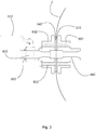
- FIG 3 shows an enlarged detail in longitudinal section of Figure 2 ; equal parts correspond to the same numbers.
- the tap 602 provided with the lever 612 which controls the ball valve 622, is mounted on the membrane 2 thanks to a flanged body 632, which is coupled, with the interposition of the gaskets 642 and 672, to another flanged body 652 arranged inside the membrane 2, and provided with an axial duct 662.
- the two flanged bodies 632 and 652 are clamped together by the bolts 682.
- This type of constructive solution for what is referred to herein as the partial discharge valve 602, can be used for all outputs or inlets of the membrane 2.
- FIG. 4 illustrates a third embodiment of the apparatus according to the present invention.
- the membrane 4 made of elastomeric material is in this case enclosed in an external steel casing 3, provided with the layer 103 of insulating material inside which the heat exchange coil 203 is arranged.
- the outer casing is provided with the door 303, while the membrane 4 is equipped with the autoclave door 304.
- the membrane 4 is also provided with the washing duct 204 and the vent duct 104, at the free end of which the manometer 114 is positioned.
- the partial discharge tap 604 On the wall of the membrane 4, and through the wall of the housing 3 emerge: the partial discharge tap 604, the total drain tap 404, and the CO 2 discharge duct 504.
- the container is equipped with the level indicator 403, and rests on the legs 31, while it can be lifted thanks to the towage rings 32.
- the container for the apparatus for the production of sparkling wines according to the present invention has a substantially spherical shape, which differentiates it radically from the containers of the known type.
- the spherical shape has an advantage linked to the isotropy of the pressure that develops inside the container during the refermentation of the wine.
- the spherical shape favors the homogeneous distribution of carbon dioxide inside the container, and therefore reduces the need for agitation, which can also be omitted, and reduces overall fermentation times.
- the container according to the embodiment shown in Figure 1 can be made by welding a plurality of spherical spindles; the number of spindles used derives from the correct compromise between harmonious development of the container and simplicity of construction.
- a preferable choice can be that of realizing a plurality of spherical spindles equal to each other, of amplitude between 30 ° and 60 °, and composing them by welding, preferably TIG welding.
- the container of the embodiment illustrated in Figure 2 i.e. the membrane made of elastomeric material, has the advantage of starting from the first stages of fermentation to counteract the increase in volume of the wine, subjecting it to its own elastic recall force.
- the elastomeric material used for the membrane 2 is preferably selected from those which exhibit a tensile strength between 7 and 21 MPa, an elongation between 100% and 400%, and preferably 200%, and a good elastic yield.
- the elastomeric material must also be provided with a good thermal inertia and a high resistance to water, to acids diluted in aqueous solution, to ethyl alcohol, and showing a low permeability to gases.
- the elastomeric material will be an EPDM (ethylene propylene diene monomer), i.e. a terpolymer of ethylene and propylene grafted with a non-conjugated diene.
- EPDM ethylene propylene diene monomer
- the thickness of the membrane will be between 1.0 mm and 4.0 mm, and preferably from 1.5 mm to 3.0 mm, more preferably of a thickness in the order of 2.0 mm.
- the membrane 4, contained within the steel casing 3, can be made with reduced mechanical performances with respect to the membrane 2 described above, since the pressure inside said membrane is distributed on the walls of the outer casing 3.
- the ducts connected to the membrane 4 cross the wall of the casing by means of slots, not shown in the figure, which guide the radial sliding, without preventing their movement.
- the apparatus for the production of sparkling wine allows to obtain a sparkling wine of better quality, through a more effective distribution of the pressure inside the fermenting product, and with a reduction in the fermentation times and in the need for agitation .
Landscapes
- Chemical & Material Sciences (AREA)
- Organic Chemistry (AREA)
- Engineering & Computer Science (AREA)
- Bioinformatics & Cheminformatics (AREA)
- Life Sciences & Earth Sciences (AREA)
- Biochemistry (AREA)
- Health & Medical Sciences (AREA)
- General Engineering & Computer Science (AREA)
- General Health & Medical Sciences (AREA)
- Genetics & Genomics (AREA)
- Wood Science & Technology (AREA)
- Zoology (AREA)
- Food Science & Technology (AREA)
- Devices For Dispensing Beverages (AREA)
- Distillation Of Fermentation Liquor, Processing Of Alcohols, Vinegar And Beer (AREA)
Abstract
Description
- The present invention relates to the production of wine, and particularly it relates to an apparatus for the production of sparkling wines.
- Sparkling wines are generally obtained by second fermentation of a wine, or an assembly of wines, with the addition of appropriate amounts of sugars and yeasts, in a pressurized environment. The two main operating lines follow the so-called classic method, or champenois, in which the second fermentation is conducted directly in the bottle, or the Martinotti-Charmat method, in which the second fermentation is carried out on large quantities of wine in special containers, the so-called autoclaves.
- If, as regards the classic method, that is the refermentation in the bottle, the technologies that have developed over time have generally concerned the chemical aspects, that is the selection and production of yeasts, and of aid to production, that is the operations of handling of the bottles such as rotation and inclination variation, in the Charmat method the impact of technologies has been characterized by the development of control systems for the environmental conditions inside the autoclave, the agitation, and the development of the structure of the autoclave itself, whose manufacturing technique has gone hand in hand with that of similar equipment used in the chemical and pharmaceutical industry.
- However, a peculiarity of these reactors which has stimulated the research that led to the present invention is linked to the characteristic shape of the autoclaves, which for decades has been substantially unchanged, and which comprises a substantially cylindrical body with two spherical caps at the ends. This shape, which allows a good management of the spaces in the area destined for production, has however the drawback, only partly obviated by the presence of stirring means, of an uneven distribution of the pressure inside the reactor, which can have as a consequence of an inhomogeneous distribution of CO2, both dissolved and total, with an impact on the characteristic perlage of sparkling wine and also on the organoleptic properties of the product obtained; to obtain high level results, it is normally necessary to have the product "worked" for a long enough time so that it is sufficiently balanced.
- The aim of the present invention is therefore to provide an apparatus for the production of sparkling wines which spontaneously allows a better and more homogeneous distribution of the pressure inside it, and thus favors the correct balance between carbon dioxide and the aqueous phase in reduced times. Object of the present invention is therefore an apparatus for the production of sparkling wines comprising a pressurized container adapted to withstand a pressure of at least 6 bar, and preferably of at least 8 bar, provided with a suitable access provided with autoclave closure; said container is substantially spherical in shape.
- In a first embodiment, said spherical container is made of stainless steel, provided with an inner insulation layer and provided with heat-exchanging means. The wall of this container has a thickness of between 0.2 mm and 1.00 mm, and preferably between 0.3 mm and 0.7 mm, more preferably it has a thickness of 0.5 mm. The container is preferably made by joining a plurality of spherical spindles, with two spherical caps arranged at the diametral ends of said spindles. The various parts of the container wall are assembled by welding, such as TIG welding. The container has a capacity in the order of 15-40 hi, and preferably in the order of 25 hi; against this capacity the container has a radius between about 0.7 m and about 1.0 m.
- The insulating layer has a thickness that can range from 2.0 mm to 15.0 mm, depending on the insulating material used and the design needs of the container; in particular it is considered advantageous to insulate with a layer in the order of 10.0 mm of expanded polyurethane, typically with a closed cell, which can be suitably surface treated to be adapted to the food requirements, or it can be enclosed in a gap with a further spherical wall in steel.
- In a second embodiment, said spherical container is a membrane of elastomeric material, with a wall thickness in the range of 1.0 to 4.0 mm, and preferably from 1.5 mm to 3.0 mm, more preferably of thickness in the order of 2.0 mm. The elastomeric material is selected from those which exhibit a tensile strength between 7 and 21 MPa, an elongation between 100% and 400%, and preferably 200%, and a good elastic yield. The elastomeric material must also be equipped with a good thermal inertia and a high resistance to water, to acids diluted in aqueous solution, to ethyl alcohol, and a low permeability to gases. Among the different elastomeric materials, it is therefore advantageous to choose those that are appropriate for food use; preferably, the elastomeric material will be an EPDM (ethylene propylene diene monomer), i.e. a terpolymer of ethylene and propylene grafted with a non-conjugated diene.
- The container will have an initial volume equal to about 50% of the volume of a similar rigid-walled container, and will reach a volume, in the working regime, in the order of 15-40 hi. The container will be conveniently supported in a substantially cubic frame structure, provided with tie-rods in elastic material secured at one end to the container itself, and at the other end to one of the vertices of said frame. The container is provided with an autoclave door, and with a plurality of openings controlled by suitable valve means, and realized by tightening the wall of the container membrane with suitable seals. Inside the membrane are placed the heat exchange elements, preferably two plates with circulating ethylene glycol.
- In a further embodiment, the spherical container is a membrane made of elastomeric material enclosed in a stainless steel casing, and is in practice a synthesis of the two embodiments described above; the external casing has the function of limiting the expansion of the elastomeric membrane, and therefore of controlling more effectively the sparkling pressure; the service ducts that are connected to the wall of the membrane pass through the openings formed in the outer casing with the appropriate clearances. The external casing in steel and the membrane in elastomeric material have substantially the same peculiarities described above.
- Further advantages and characteristics of the apparatus according to the present invention will become clear from the detailed description of some embodiments of the same given, by way of example and not for limiting purposes, with reference to the tables of attached drawings, in which:
-
figure 1 is a front elevation view with parts in section of a first embodiment of the apparatus according to the present invention; -
figure 2 is a front elevation view with parts in section of a second embodiment of the apparatus according to the present invention; -
figure 3 is a longitudinal section view of an enlarged detail offigure 2 ; and -
Figure 4 is a front elevation view with parts in section of a third embodiment of the apparatus according to the present invention. -
Figure 1 shows a first embodiment of the apparatus according to the present invention; 1 indicates the steel spherical container. Said container is provided with alayer 101 of insulating material, inside which theheat exchange coil 201 is arranged, in which typically ethylene glycol circulates. Thecontainer 1 is provided with therectangular autoclave door 301, which opens inwards with anelliptical profile 301. From the top of thecontainer 1 emerge thewashing duct 501 and thevent 401, at whose free end thepressure gauge 411 is located. On the side wall thepartial drain cock 601 is provided, while at the pole opposite to that from which theducts total discharge tap 801 is provided, near which the CO2 discharge duct is located. Thecontainer 1 is supported by thelegs 11, and can be lifted thanks to thetowage rings 12. Thecontainer 1 is also provided with thelevel indicator 701. -
Figure 2 illustrates a second embodiment of the apparatus according to the present invention; 2 indicates the spherical container, which in this case is a membrane made of elastomeric material, capable of expanding in volume up to the dimensions shown with the dotted line and indicated with 2 '. Themembrane 2 is provided with avent duct 402, at the free end of which apressure gauge 412 is placed; inside themembrane 2 twoheat exchange plates 102 are arranged, which are fed through therespective openings 112. The membrane is equipped with anautoclave door 302 with an elliptical profile, as well as an elliptical profile is shown by its portion facing theinterior 312. Thepartial discharge tap 602 is located on the membrane, in addition to thetotal discharge tap 702 and the CO2 discharge duct 502. Thespherical membrane 2 is connected to fourtie rods 21 in therespective hooking points 22, and thetie rods 21 at the opposite end are coupled to four vertices of acubic frame 20. -
Figure 3 shows an enlarged detail in longitudinal section ofFigure 2 ; equal parts correspond to the same numbers. Thetap 602, provided with thelever 612 which controls theball valve 622, is mounted on themembrane 2 thanks to aflanged body 632, which is coupled, with the interposition of thegaskets body 652 arranged inside themembrane 2, and provided with anaxial duct 662. The twoflanged bodies bolts 682. This type of constructive solution, for what is referred to herein as thepartial discharge valve 602, can be used for all outputs or inlets of themembrane 2. -
Figure 4 illustrates a third embodiment of the apparatus according to the present invention. Themembrane 4 made of elastomeric material is in this case enclosed in anexternal steel casing 3, provided with thelayer 103 of insulating material inside which theheat exchange coil 203 is arranged. The outer casing is provided with thedoor 303, while themembrane 4 is equipped with theautoclave door 304. Themembrane 4 is also provided with thewashing duct 204 and thevent duct 104, at the free end of which themanometer 114 is positioned. On the wall of themembrane 4, and through the wall of thehousing 3 emerge: thepartial discharge tap 604, thetotal drain tap 404, and the CO2 discharge duct 504. The container is equipped with thelevel indicator 403, and rests on thelegs 31, while it can be lifted thanks to thetowage rings 32. - The operation and structure of the apparatus according to the present invention will appear evident from the following. In all the illustrated embodiments, the container for the apparatus for the production of sparkling wines according to the present invention has a substantially spherical shape, which differentiates it radically from the containers of the known type. In particular, the spherical shape has an advantage linked to the isotropy of the pressure that develops inside the container during the refermentation of the wine. In fact, the spherical shape favors the homogeneous distribution of carbon dioxide inside the container, and therefore reduces the need for agitation, which can also be omitted, and reduces overall fermentation times.
- The container according to the embodiment shown in
Figure 1 can be made by welding a plurality of spherical spindles; the number of spindles used derives from the correct compromise between harmonious development of the container and simplicity of construction. A preferable choice can be that of realizing a plurality of spherical spindles equal to each other, of amplitude between 30 ° and 60 °, and composing them by welding, preferably TIG welding. - The container of the embodiment illustrated in
Figure 2 , i.e. the membrane made of elastomeric material, has the advantage of starting from the first stages of fermentation to counteract the increase in volume of the wine, subjecting it to its own elastic recall force. The elastomeric material used for themembrane 2 is preferably selected from those which exhibit a tensile strength between 7 and 21 MPa, an elongation between 100% and 400%, and preferably 200%, and a good elastic yield. The elastomeric material must also be provided with a good thermal inertia and a high resistance to water, to acids diluted in aqueous solution, to ethyl alcohol, and showing a low permeability to gases. - Among the different elastomeric materials, it is therefore advantageous to choose those that are appropriate for food use; preferably, the elastomeric material will be an EPDM (ethylene propylene diene monomer), i.e. a terpolymer of ethylene and propylene grafted with a non-conjugated diene. The thickness of the membrane will be between 1.0 mm and 4.0 mm, and preferably from 1.5 mm to 3.0 mm, more preferably of a thickness in the order of 2.0 mm.
- In the embodiment of
Figure 4 the effects obtained with the previously described solutions are advantageously combined; in practice, themembrane 4, contained within thesteel casing 3, can be made with reduced mechanical performances with respect to themembrane 2 described above, since the pressure inside said membrane is distributed on the walls of theouter casing 3. The ducts connected to themembrane 4 cross the wall of the casing by means of slots, not shown in the figure, which guide the radial sliding, without preventing their movement. - The apparatus for the production of sparkling wine according to the present invention allows to obtain a sparkling wine of better quality, through a more effective distribution of the pressure inside the fermenting product, and with a reduction in the fermentation times and in the need for agitation .
Claims (13)
- Apparatus for the production of sparkling wines, comprising a pressurized container suitable for withstanding a pressure of at least 6 bars, and preferably at least 8 bars, provided with an appropriate access provided with an autoclave closure, characterized in that said container is substantially spherical in shape .
- Apparatus according to claim 1, wherein said spherical container is made of stainless steel, provided with an inner insulating layer and equipped with heat-exchanging means.
- Apparatus according to claim 2, wherein the wall of said container has a thickness comprised between 0.2 mm and 1.00 mm, and preferably between 0.3 mm and 0.7 mm, more preferably it has a thickness of 0, 5 mm.
- Apparatus according to claim 2 or 3, wherein the container is made by joining a plurality of spherical wedges, with two spherical caps arranged at the diametrical ends of said wedges.
- Apparatus according to any one of the preceding claims from 2 to 4, wherein the container has a capacity in the order of 15-40 hi, and preferably in the order of 25 hi.
- Apparatus according to any one of the preceding claims from 2 to 5, wherein the insulating layer has a thickness from 2.0 mm to 15.0 mm.
- Apparatus according to claim 1, wherein said spherical container is a membrane made of elastomeric material, having a wall thickness in the order of from 1.0 to 4.0 mm, and preferably from 1.5 mm to 3.0 mm, more preferably of thickness in the order of 2.0 mm.
- Apparatus according to claim 7, wherein the elastomeric material is selected from those exhibiting a tensile strength between 7 and 21 MPa, an elongation between 100% and 400%, and preferably 200%, and a good elastic yield.
- Apparatus according to claim 8, wherein the elastomeric material is an EPDM (ethylene propylene diene monomer), i.e. a terpolymer of ethylene and propylene grafted with an unconjugated diene.
- Apparatus according to any one of the preceding claims from 7 to 9, wherein the container is conveniently supported in a substantially cubic frame structure, provided with tie rods made of elastic material secured at one end to the container itself, and at the other end to one of the vertices of said frame.
- Apparatus according to any one of the preceding claims from 7 to 10, wherein the container is provided with an autoclave door, and a plurality of openings controlled by suitable valve means, and realized by tightening the wall of the container membrane with suitable seals.
- Apparatus according to any one of the preceding claims from 7 to 11, wherein the heat exchange elements, preferably two ethylene glycol circulation plates, are located inside the membrane.
- Apparatus according to claim 1, wherein the spherical container is a membrane made of elastomeric material enclosed in a stainless steel casing, the external steel casing is made according to one or more of the previous claims from 2 to 6, and the membrane made of material elastomeric is made according to one or more of the previous claims from 7 to 12.
Applications Claiming Priority (1)
| Application Number | Priority Date | Filing Date | Title |
|---|---|---|---|
| IT102018000006148A IT201800006148A1 (en) | 2018-06-08 | 2018-06-08 | Apparatus for the production of sparkling wines |
Publications (1)
| Publication Number | Publication Date |
|---|---|
| EP3578632A1 true EP3578632A1 (en) | 2019-12-11 |
Family
ID=63491881
Family Applications (1)
| Application Number | Title | Priority Date | Filing Date |
|---|---|---|---|
| EP19177605.3A Withdrawn EP3578632A1 (en) | 2018-06-08 | 2019-05-31 | Apparatus for the production of sparkling wines |
Country Status (2)
| Country | Link |
|---|---|
| EP (1) | EP3578632A1 (en) |
| IT (1) | IT201800006148A1 (en) |
Citations (3)
| Publication number | Priority date | Publication date | Assignee | Title |
|---|---|---|---|---|
| FR1220738A (en) * | 1959-04-22 | 1960-05-27 | C Berger & Cie Ets | Improvements made to sparkling wine manufacturing processes, and special vats allowing these improvements to be made |
| GB1076035A (en) * | 1963-10-10 | 1967-07-19 | Marius Alphonsus Johannes Verl | Improvments in or relating to pressure containers |
| RU2264777C1 (en) * | 2004-08-20 | 2005-11-27 | Крапивкин Павел Владимирович | Autoclave |
-
2018
- 2018-06-08 IT IT102018000006148A patent/IT201800006148A1/en unknown
-
2019
- 2019-05-31 EP EP19177605.3A patent/EP3578632A1/en not_active Withdrawn
Patent Citations (3)
| Publication number | Priority date | Publication date | Assignee | Title |
|---|---|---|---|---|
| FR1220738A (en) * | 1959-04-22 | 1960-05-27 | C Berger & Cie Ets | Improvements made to sparkling wine manufacturing processes, and special vats allowing these improvements to be made |
| GB1076035A (en) * | 1963-10-10 | 1967-07-19 | Marius Alphonsus Johannes Verl | Improvments in or relating to pressure containers |
| RU2264777C1 (en) * | 2004-08-20 | 2005-11-27 | Крапивкин Павел Владимирович | Autoclave |
Also Published As
| Publication number | Publication date |
|---|---|
| IT201800006148A1 (en) | 2019-12-08 |
Similar Documents
| Publication | Publication Date | Title |
|---|---|---|
| US3863460A (en) | Device for the storage and transport of liquified gases, liquids and the like, in particular on ships | |
| KR20190020317A (en) | Gas Dome Structures for Sealed Insulated Vessels | |
| US3140792A (en) | Pressure vessel closure member | |
| CN106439484B (en) | Low temperature two-tube loading arm peculiar to vessel | |
| JP6667717B2 (en) | Method for assembling a transport tank in a ship and corresponding ship | |
| KR20230009428A (en) | Liquid dome of a storage tank for liquefied gas, having an opening with an additional hatch | |
| US2925934A (en) | Support means for the movable end of a vessel | |
| US20110002816A1 (en) | Polymerisation reactor | |
| CA1056317A (en) | Pressure vessel construction and method | |
| US3047190A (en) | Beer fermenting tank | |
| Błachut et al. | On the choice of initial geometric imperfections in externally pressurized shells | |
| US2451486A (en) | Vacuum tank for storing liquids at high or low temperatures | |
| IT201800006148A1 (en) | Apparatus for the production of sparkling wines | |
| JP2026001004A (en) | Large-scale vacuum insulated cryogenic storage | |
| US3984994A (en) | Process and device for filling multilayer pressure containers | |
| Ting | High-pressure processing equipment fundamentals | |
| US7077282B2 (en) | Explosion-proof container | |
| US11420175B2 (en) | Differential hydrogenation reaction apparatus | |
| US20250003553A1 (en) | Isolable double-walled insulation tank for launch vehicle | |
| EP2880999A1 (en) | High pressure container for withstanding fatigue operating cycles | |
| CN205686926U (en) | A kind of oil storage tank hatch frame | |
| CN212251521U (en) | Heat insulation tantalum-tungsten alloy pipe | |
| US6213337B1 (en) | Metal body for packaging purposes, for example a food can | |
| JP2004513777A (en) | Autoclave pressurization module | |
| CN207512235U (en) | It is simple reliably to roll steel heat treatment materials frame |
Legal Events
| Date | Code | Title | Description |
|---|---|---|---|
| PUAI | Public reference made under article 153(3) epc to a published international application that has entered the european phase |
Free format text: ORIGINAL CODE: 0009012 |
|
| AK | Designated contracting states |
Kind code of ref document: A1 Designated state(s): AL AT BE BG CH CY CZ DE DK EE ES FI FR GB GR HR HU IE IS IT LI LT LU LV MC MK MT NL NO PL PT RO RS SE SI SK SM TR |
|
| AX | Request for extension of the european patent |
Extension state: BA ME |
|
| STAA | Information on the status of an ep patent application or granted ep patent |
Free format text: STATUS: THE APPLICATION HAS BEEN WITHDRAWN |
|
| 17P | Request for examination filed |
Effective date: 20200609 |
|
| RBV | Designated contracting states (corrected) |
Designated state(s): AL AT BE BG CH CY CZ DE DK EE ES FI FR GB GR HR HU IE IS IT LI LT LU LV MC MK MT NL NO PL PT RO RS SE SI SK SM TR |
|
| 18W | Application withdrawn |
Effective date: 20200611 |