EP3578456A1 - Puck cover - Google Patents
Puck cover Download PDFInfo
- Publication number
- EP3578456A1 EP3578456A1 EP18184588.4A EP18184588A EP3578456A1 EP 3578456 A1 EP3578456 A1 EP 3578456A1 EP 18184588 A EP18184588 A EP 18184588A EP 3578456 A1 EP3578456 A1 EP 3578456A1
- Authority
- EP
- European Patent Office
- Prior art keywords
- puck
- cover
- rotorcraft
- seats
- aircraft
- Prior art date
- Legal status (The legal status is an assumption and is not a legal conclusion. Google has not performed a legal analysis and makes no representation as to the accuracy of the status listed.)
- Granted
Links
Images







Classifications
-
- F—MECHANICAL ENGINEERING; LIGHTING; HEATING; WEAPONS; BLASTING
- F16—ENGINEERING ELEMENTS AND UNITS; GENERAL MEASURES FOR PRODUCING AND MAINTAINING EFFECTIVE FUNCTIONING OF MACHINES OR INSTALLATIONS; THERMAL INSULATION IN GENERAL
- F16B—DEVICES FOR FASTENING OR SECURING CONSTRUCTIONAL ELEMENTS OR MACHINE PARTS TOGETHER, e.g. NAILS, BOLTS, CIRCLIPS, CLAMPS, CLIPS OR WEDGES; JOINTS OR JOINTING
- F16B37/00—Nuts or like thread-engaging members
- F16B37/14—Cap nuts; Nut caps or bolt caps
-
- B—PERFORMING OPERATIONS; TRANSPORTING
- B64—AIRCRAFT; AVIATION; COSMONAUTICS
- B64C—AEROPLANES; HELICOPTERS
- B64C1/00—Fuselages; Constructional features common to fuselages, wings, stabilising surfaces or the like
- B64C1/18—Floors
- B64C1/20—Floors specially adapted for freight
-
- B—PERFORMING OPERATIONS; TRANSPORTING
- B64—AIRCRAFT; AVIATION; COSMONAUTICS
- B64C—AEROPLANES; HELICOPTERS
- B64C27/00—Rotorcraft; Rotors peculiar thereto
- B64C27/04—Helicopters
-
- B—PERFORMING OPERATIONS; TRANSPORTING
- B64—AIRCRAFT; AVIATION; COSMONAUTICS
- B64D—EQUIPMENT FOR FITTING IN OR TO AIRCRAFT; FLIGHT SUITS; PARACHUTES; ARRANGEMENT OR MOUNTING OF POWER PLANTS OR PROPULSION TRANSMISSIONS IN AIRCRAFT
- B64D11/00—Passenger or crew accommodation; Flight-deck installations not otherwise provided for
- B64D11/06—Arrangements of seats, or adaptations or details specially adapted for aircraft seats
- B64D11/0601—Arrangement of seats for non-standard seating layouts, e.g. seats staggered horizontally or vertically, arranged in an angled or fishbone layout, or facing in other directions than the direction of flight
-
- B—PERFORMING OPERATIONS; TRANSPORTING
- B64—AIRCRAFT; AVIATION; COSMONAUTICS
- B64D—EQUIPMENT FOR FITTING IN OR TO AIRCRAFT; FLIGHT SUITS; PARACHUTES; ARRANGEMENT OR MOUNTING OF POWER PLANTS OR PROPULSION TRANSMISSIONS IN AIRCRAFT
- B64D11/00—Passenger or crew accommodation; Flight-deck installations not otherwise provided for
- B64D11/06—Arrangements of seats, or adaptations or details specially adapted for aircraft seats
- B64D11/0696—Means for fastening seats to floors, e.g. to floor rails
Definitions
- This disclosure relates generally to aircraft mounts, and more particularly, though not exclusively, to a puck cover.
- aircraft fixtures may vary greatly based on various factors, including the type of aircraft, the purpose of the aircraft, and any other needs or requirements of an aircraft operator (such as business and/or legal related requirements), among other examples.
- a puck cover can be removably coupled to a puck of a rotorcraft.
- the puck cover can include a top cover surface, a center support, and a plurality of extensions.
- the top cover can be a solid surface and/or textured and have a curved or square shaped profile.
- a seal can be around the top cover surface to help keep liquids and/or foreign object debris (FOD) out of the puck.
- grippers can be under the top cover surface to help keep the puck cover from sliding or moving on a carpeted or other similar surface.
- the puck can be configured to be embedded in a structure of the rotorcraft and the puck can include an attachment post for coupling a removable fixture to the structure in which the puck is embedded.
- the structure of the rotorcraft is a floor panel of the rotorcraft.
- the puck creates a cavity in the structure when the fixture is not coupled to the attachment post and the puck cover can cover the cavity in the structure when the fixture is not coupled to the attachment post.
- the plurality of extensions of the puck cover can couple with the attachment post.
- the center support can be over the attachment post.
- the present disclosure may repeat reference numerals and/or letters in the various examples. This repetition is for the purpose of simplicity and clarity and does not in itself dictate a relationship between the various embodiments and/or configurations discussed.
- the phrase "A and/or B" means (A), (B), or (A and B).
- the phrase "A, B, and/or C” means (A), (B), (C), (A and B), (A and C), (B and C), or (A, B, and C).
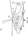
- FIGURES 1A and 1B illustrate an example embodiment of a rotorcraft 100.
- FIGURE 1A illustrates a side view of rotorcraft 100
- FIGURE 1B illustrates a perspective view of rotorcraft 100.
- Rotorcraft 100 includes a rotor system 102 with a plurality of rotor blades 104. The pitch of each rotor blade 104 can be managed or adjusted in order to selectively control direction, thrust, and lift of rotorcraft 100.
- Rotorcraft 100 further includes a fuselage 106, tail rotor or anti-torque system 108, an empennage 110, and a tail structure 112. In the illustrated embodiment, tail structure 112 may be used as a horizontal stabilizer.
- Torque is supplied to rotor system 102 and anti-torque system 108 using at least one engine 114.
- Airframe 118 includes the outer covering of rotorcraft 100
- FIGURE 2 illustrates a perspective view of an example tiltrotor aircraft 120.
- Tiltrotor aircraft 120 can include nacelles 122a and 122b, a wing 124, a fuselage 126, and a tail member 128.
- Each nacelle 122a and 122b can include an engine and gearbox for driving rotor systems 130a and 130b, respectively.
- Nacelles 122a and 122b are each configured to rotate between a helicopter mode, in which the nacelles 122a and 122b are approximately vertical, and an airplane mode, in which the nacelles 122a and 122b are approximately horizontal.
- rotorcraft 100 of FIGURES 1A and 1B and tiltrotor aircraft 120 of FIGURE 2 are merely illustrative of a variety of aircraft that can be used to implement embodiments of the present disclosure.
- Other aircraft implementations can include, for example, fixed wing airplanes, hybrid aircraft, unmanned aircraft, gyrocopters, and a variety of helicopter configurations, among other examples.
- helicopter configurations among other examples.
- aircraft are particularly well suited to implement embodiments of the present disclosure, the described embodiments can also be implemented using non-aircraft vehicles and devices.
- aircraft fixtures may vary greatly based on various factors, including the type of aircraft, the purpose of the aircraft, and any other needs or requirements of an aircraft operator (such as business and/or regulatory related requirements), among other examples.
- Fixed wing airplanes, rotorcrafts (e.g., helicopters), tiltrotor aircraft, and other aircraft may be used for commercial and/or private travel, cargo transportation, military purposes, and oil and gas exploration, among other examples.
- the interior configurations of these aircraft typically vary based on the type and purpose of each aircraft. For example, the number, size, and arrangement of seats in an aircraft may vary. Aircraft used for commercial travel (e.g., airplanes), for example, may require more seats than aircraft used for private travel, corporate travel, or oil and gas exploration, among other examples. Moreover, aircraft used for corporate or private travel may require custom configurations of seats and/or other interior fixtures, such as tables, cabinets, storage compartments, desks, office equipment and furniture, entertainment equipment and furniture, and beds, among other examples. Certain types and/or uses of aircraft may also be subject to business and/or legal constraints that impact the interior configuration required for the aircraft, such as government safety regulations.
- certain aircraft may be subject to government regulations relating to seating configuration, emergency exits, and cargo or luggage storage, such as regulations issued by the Federal Aviation Administration (FAA).
- Transport rotorcraft e.g., helicopters
- FAA regulations associated with the number of seats, seat and aisle spacing, access to emergency exits, and so forth (e.g., as set forth by various regulations from 14 C.F.R. ⁇ 29).
- rotorcraft used for oil and gas exploration may be subject to OGP operator standards (e.g., enhanced safety standards) for operations pursued under the International Association of Oil and Gas Producers (the IOGP or OGP).
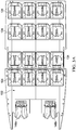
- FIGURE 3A illustrates an example seating arrangement for 16 passengers.
- a floor 132 of a rotorcraft is shown and an arrangement of 16 seats 134 and pilot seats 146a and 146b are installed in rotorcraft floor 132.
- pilot seat 146a may be the captain or pilot's seat while pilot seat 146b may be a co-pilot seat.
- the seats in the 1st, 3rd, and 4th rows all face towards the front of the rotorcraft, while the seats in the 2nd row face towards the back of the rotorcraft. In this manner, the seats in the 2nd and 3rd rows (e.g., the two middle rows) face each other.
- FIGURE 3B illustrates a passenger seating arrangement with fold over seats 136.
- the illustrated seating arrangement of FIGURE 3B is similar to the 16-passenger seating arrangement of FIGURE 3A , except with four fewer seats 134 and the seating arrangement of FIGURE 3B includes fold over seats 136 on the left and right ends of the 3rd row.
- the seats in the 1st, 3rd, and 4th rows all face towards the front of the rotorcraft, while the seats in the 2nd row face towards the back of the rotorcraft.
- the seats in the 2nd and 3rd rows e.g., the two middle rows
- the two seats on the left and right ends of the 3rd row are fold over seats 136, which may facilitate emergency exit access and egress for certain passengers.
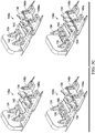
- FIGURE 3C illustrates a three-dimensional perspective of various corporate fixture (e.g., seats, furniture, compartments, and/or other fixtures) configurations 138a-d.
- configuration 138a is a 4-passenger seating configuration.
- a storage compartment (or other desired fixture) can be located at the back of the rotorcraft.
- the seats in the 1st row face towards the back of the rotorcraft, while the seats in the 2nd row face towards the front of the rotorcraft. In this manner, the seats in the 1st and 2nd rows face each other.
- Configuration 138b is a 5-passenger seating configuration. As shown, there are two rows of seats 134, with three seats in the 1st row and two seats in the 2nd row, center table 140 is between the seat rows, and side table 142 is between two seats 134.
- a storage compartment (or other desired fixture) can be located at the back of the rotorcraft. The seats in the 1st row face towards the back of the rotorcraft, while the seats in the 2nd row face towards the front of the rotorcraft. In this manner, the seats in the 1st and 2nd rows face each other.
- Configuration 138c is a 6-passenger seating configuration. As shown in the illustrated example, there are two rows of seats 134, with three seats per row and a center table 140 between the seat rows. Moreover, the center seat of the 2nd row is a fold over seat (e.g., fold over seat 136), which may facilitate access to a storage compartment (or other desired fixture) at the back of the rotorcraft.
- the seats in the 1st row face towards the back of the rotorcraft, while the seats in the 2nd row face towards the front of the rotorcraft. In this manner, the seats in the 1st and 2nd rows face each other.
- Configuration 138d is an 8-passenger seating configuration. As shown, there are two rows of seats 134, with four seats per row and a center table 140 between the seat rows. A storage compartment (or other desired fixture) can be located at the back of the rotorcraft. The two middle seats of the 2nd row are fold over seats (e.g., fold over seat 136), which may facilitate access to the storage compartment at the back of the rotorcraft.
- the seats in the 1st row face towards the back of the rotorcraft, while the seats in the 2nd row face towards the front of the rotorcraft. In this manner, the seats in the 1st and 2nd rows face each other.
- any desired fixture(s) can be installed at the back of the rotorcraft (e.g., a storage or baggage compartment, cabinetry, beverage center, ice bins, and so forth) depending on user preference.
- Seats 134, fold over seats 136, center table 140, side table 142, and other furniture, storage, fixture, etc. can be attached to rotorcraft floor 132 using one or more pucks and other seat attachment mechanisms.
- FIGURE 4 illustrates example configurations of pucks 144 in the floor 132 of a rotorcraft.
- pilot seats 146a and 146b are attached to rotorcraft floor 132.
- rotorcraft floor 132 includes an arrangement of pucks 144 that can have different shapes, sizes, numbers of attachment points, and spacing between each puck 144.
- the fixtures e.g., seats, furniture, compartments, and/or other fixtures
- the particular configuration and design of pucks 144 used in the illustrated example is for illustration purposes only.
- a rotorcraft may use a single floor panel that supports multiple seating arrangements.
- the particular approach may depend on the needs and/or requirements of an operator of the rotorcraft.
- FIGURE 5 illustrates an example embodiment of a puck 144.
- puck 144 is installed in surface 148.
- surface 148 may be a surface or structure of an aircraft, such as the floor panel of a rotorcraft or a wall.
- surface 148 may comprise a composite core, such as a honeycomb or foam core. In other embodiments, however, any suitable type of surface 148 may be used.
- puck 144 includes an attachment point 150.
- Attachment point 150 may be used as an attachment point for fixtures (e.g., seats, furniture, compartments, and/or other fixtures attached to surface 148 in which puck 144 is embedded).
- a fixture can include a corresponding attachment point or fitting that can be mechanically clamped down on attachment point 150 of puck 144.
- the fixture may be installed by clamping down its attachment point(s) to the attachment point(s) 150 of one or more pucks 144.
- attachment point 150 of puck 144 may include a stud fastened to puck 144 using mechanical fasteners (e.g., a locking nut and washers), and the stud of puck 144 may interface with a corresponding attachment point of a particular fixture.
- mechanical fasteners e.g., a locking nut and washers
- puck 144 may include multiple attachment points 150.
- puck 144 also includes flanges 152a and 152b.
- puck 144 may be formed from two adjacent and internal flanges 152a and 152b.
- puck 144 may be formed using two vertically arranged components that each include flanges 152a and 152b, with flanges 152a and 152b situated internally and adjacent to each other when puck 144 is embedded within a particular surface 148.
- Flanges 152a and 152b may each include an internal ridge or rim that provides structural support and strength when puck 144 is used as an attachment point for a fixture.
- flanges 152a and 152b may provide a load path for transferring and/or shearing the load over a given area of surface 148 in which puck 144 is installed.
- the two components with flanges 152a and 152b may be distinct or separable parts of puck 144.
- puck 144 may be installed in a particular surface 148 by first drilling a hole in surface 148, and then placing two flange components (e.g., flanges 152a and 152b) of the puck 144 in the hole, with the flanges arranged adjacently in the hole and with attachment point 150 in the center. In this manner, puck 144 can be mechanically clamped or installed in the drilled hole, thus avoiding the need to use an adhesive bond to hold puck 144 in place. In some embodiments, however, an adhesive bond may still be used or injected, for example, in order to seal any gaps (e.g., to prevent moisture). In this manner, pucks 144 can be installed in a particular surface 148 even after the surface has been fabricated or manufactured. For example, in some cases, blank floor panels for rotorcraft could be fabricated or manufactured, and then pucks 144 could be subsequently installed in the floor panels using the appropriate configuration (e.g., using a configuration desired by a particular rotorcraft operator).
- pucks 144 may be used to attach fixtures to the surface 148 in which they are installed (e.g., for attaching e.g., seats, furniture, compartments, and/or other fixtures).
- the fixtures may include attachment points, such as claw-based attachment fittings, which can be mechanically clamped down on the corresponding attachment points 150 of pucks 144.
- fixtures can be installed by clamping down their attachment points to the appropriate attachment points 150 of pucks 144.
- Fixtures can similarly be removed by disconnecting the fixture attachments points from the corresponding attachment points 150 of the pucks 144.
- the configuration of fixtures e.g., seating configurations
- the configuration of fixtures can be relatively easily modified, for example, by adding, removing, and/or rearranging certain fixtures, as desired.
- pucks 144 may enable fixtures to be configured in a more flexible manner than is possible using other attachment mechanisms, such as rail-based mechanisms, which may require all or many of the existing fixtures to be removed from the rails in order to add, remove, and/or rearrange certain fixtures on the rails (e.g., by sliding the existing fixtures off the rails, and then sliding fixtures back on the rails using a new fixture arrangement). Pucks 144 may also enable attachment points to be added to a particular surface 148 without compromising the flat nature of the surface, given that pucks 144 can be embedded within the surface 148 in which they are installed.
- other attachment mechanisms such as rail-based mechanisms, which may require all or many of the existing fixtures to be removed from the rails in order to add, remove, and/or rearrange certain fixtures on the rails (e.g., by sliding the existing fixtures off the rails, and then sliding fixtures back on the rails using a new fixture arrangement).
- Pucks 144 may also enable attachment points to be added to a particular surface 148 without compromising the flat
- a puck may be a cylindrical or puck shaped mechanism that can be installed in a variety of locations in an aircraft and that provides attachment point(s) for fixtures.
- Pucks may be used to attach any type of fixture to an aircraft, including but not limited to, furniture (e.g., seats, tables, cabinets, storage compartments, desks, computer stands, beds), office or entertainment equipment, cargo storage mechanisms (e.g., for secure lock-down of baggage and cargo), and litter kits, among other examples.
- pucks may be used to install fixtures in any location of an aircraft, including the main cabin, the baggage or cargo bay, the walls or roof, and even the aircraft exterior (e.g., for cargo nets, wing tie-downs, and other external features).
- Pucks can be installed in an aircraft using a variety of configurations, and the particular configuration may depend on the type of aircraft, the purpose of the aircraft, the particular fixtures that will be installed in the aircraft, and any other needs or requirements of an aircraft operator (such as business and/or regulatory related requirements), among other examples.
- pucks may be used to enable flexible seating and furniture configurations in aircraft interiors, including varying numbers of seats and various seating arrangements.
- rotorcraft may use pucks to provide seating configurations for a variable number of passengers, such as seating configurations ranging from 16 to 20 passengers.
- rotorcraft used for oil and gas exploration may use pucks to enable seating configurations that comply with FAA and OGP standards.
- pucks may be used to install particular seating arrangements and/or foldover seats in an aircraft or rotorcraft, for example, to facilitate access to the exits in a manner that complies with OGP standards (and/or any other standards, requirements, or regulations).
- rotorcraft used for corporate, private, and/or VIP travel may use pucks to enable various custom seating and furniture configurations (e.g., as desired by the operator and/or passengers).
- a possible solution is to use a puck cover.
- unused pucks can be covered or plugged with a puck cover or plug.
- the puck cover can be relatively flush with the surface in which the puck is embedded, thus enabling flexible puck-based configurations to be installed in a surface while preserving a relatively flat nature for the surface.
- the puck cover can be relatively easily removed to allow for the reconfiguration of fixtures.
- Unused pucks 144 can be covered with the puck cover to help eliminate or reduce the puck causing a hazard (e.g., tripping hazard), harboring foreign object debris (FOD), or creating, causing, or otherwise helping facilitate other issues and to preserve the relatively flat nature of surface 148 in which the pucks are embedded, while also preserving the ability to subsequently reconfigure an arrangement of fixtures using the previously unused pucks.
- a hazard e.g., tripping hazard
- FOD foreign object debris
- references to "one embodiment” or “an embodiment” in the present disclosure means that a particular feature, structure, or characteristic described in connection with the embodiment is included in at least one embodiment.
- the appearances of the phrase “in one embodiment” or “in an embodiment” are not necessarily all referring to the same embodiment.
- Figure 6 illustrates a seat 134 and side table 142 secured to floor 132 using one or more pucks 144.
- unused pucks 144 on floor 132 create holes in floor 132.
- the unused pucks 144 can create a hazard (e.g., tripping hazard), harbor foreign object debris (FOD), or create, cause, or otherwise help facilitate other issues.
- a hazard e.g., tripping hazard
- FOD foreign object debris
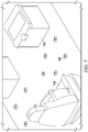
- FIG 7 illustrates each unused puck 144 (not shown) being covered by a puck cover 156.
- Puck cover 156 can be configured to snap or otherwise coupled with puck 144 and mitigate against tripping and FOD, and can withstand occupant loads when directly stepped on by transferring weight to attachment point 150 and flanges 152 (not shown).
- puck cover 156 can be relatively flat or have a slightly curved profile to help preserve the relatively flat nature of floor 132.
- FIG 8 illustrates example details of puck cover 156.
- Puck cover 156 can include a top cover surface 158, a center support 160, and extensions 162.
- Top cover surface 158 can be relatively flat or have a slight curve to help preserve the relatively flat nature of surface 148.
- Center support 160 can help puck cover 156 withstand occupant loads when directly stepped on.
- each top cover surface 158 may have a textured surface to help prevent slipping and/or for aesthetic purposes.
- Figure 9 illustrates example details of puck cover 156.
- center support 160 can be configured be located on top of or over attachment point 150 (illustrated in FIGURE 5 ).
- extension 162 can be configured to couple with the edges of attachment point 150 to help removably secure puck cover 156 to attachment point 150.
- Extension 162 can include claw-based attachment fittings which can be mechanically clamped down on an attachment point 150 of puck 144.
- extension 162 may be spring loaded or some other type of mechanism that allows puck cover 156 to be removable secured to attachment point 150.
- Figure 10 illustrates example details of puck 144 and puck cover 156.
- a carpet 168 or some other layer may be over surface 148.
- Carpet 168 can include a hole or opening that allows access to puck 144.
- Puck cover 156 can be inserted into the hole or opening of carpet 168 such that extension 162 can couple with the edges of attachment point 150 to help secure puck cover 156 to attachment point 150.
- surface 148 is a floor (e.g., floor 132)
- center support 160 can be on or over attachment point to help puck cover 156 withstand occupant loads when directly stepped on.
- occupant loads on puck cover 156 can be at least partially transferred to attachment point 150, which at least partially transfers to the load to attachment point 150 and onto the structure of puck 144.
- FIGS 11A and 11B illustrate example details of a puck cover 156a.
- Puck cover 156a can include a solid top cover surface 158, center support 160, and a seal 164.
- Seal 164 can surround top cover surface 158 and may be comprised of rubber or some other material that can help keep liquids and/or FOD out of puck 144.
- puck cover 156a can include a plurality of grippers 166.
- Grippers 166 can be configured to help keep puck cover 156a from sliding or moving on a carpeted or other similar surface where grippers can imbed in the surface and/or provide friction resistance to the movement of puck cover 156a relative to puck 144.
- FIGS 12A and 12B illustrate example details of a puck cover 156b.
- Puck cover 156b can include top cover surface 158 and center support 160.
- top cover surface 158 may have a square profile. The square profile may be for aesthetic purposes.
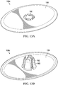
- FIGS 13A and 13B illustrate example details of a puck cover 156c.
- Puck cover 156c can include top cover surface 158 and center support 160.
- top cover surface 158 may have an oval profile. The oval profile may be for aesthetic purposes.
- some components may be implemented separately, consolidated into one or more integrated components, and/or omitted.
- methods associated with certain embodiments may be implemented using more, less, and/or other steps than those described herein, and their steps may be performed in any suitable order.
Landscapes
- Engineering & Computer Science (AREA)
- Mechanical Engineering (AREA)
- Aviation & Aerospace Engineering (AREA)
- General Engineering & Computer Science (AREA)
- Laminated Bodies (AREA)
Abstract
Description
- This disclosure relates generally to aircraft mounts, and more particularly, though not exclusively, to a puck cover.
- There are many different types of aircraft available for a variety of different purposes. The various types of aircraft may require a variety of different fixtures and associated configurations, such as seating and furniture fixtures in the aircraft interiors. The configuration of aircraft fixtures may vary greatly based on various factors, including the type of aircraft, the purpose of the aircraft, and any other needs or requirements of an aircraft operator (such as business and/or legal related requirements), among other examples.
- According to one aspect of the present disclosure a puck cover can be removably coupled to a puck of a rotorcraft. The puck cover can include a top cover surface, a center support, and a plurality of extensions. The top cover can be a solid surface and/or textured and have a curved or square shaped profile. In addition, a seal can be around the top cover surface to help keep liquids and/or foreign object debris (FOD) out of the puck. Further, grippers can be under the top cover surface to help keep the puck cover from sliding or moving on a carpeted or other similar surface.
- The puck can be configured to be embedded in a structure of the rotorcraft and the puck can include an attachment post for coupling a removable fixture to the structure in which the puck is embedded. The structure of the rotorcraft is a floor panel of the rotorcraft. The puck creates a cavity in the structure when the fixture is not coupled to the attachment post and the puck cover can cover the cavity in the structure when the fixture is not coupled to the attachment post. In an example, the plurality of extensions of the puck cover can couple with the attachment post. In addition, the center support can be over the attachment post.
-
-
Figures 1A and1B illustrate an example aircraft in accordance with certain embodiments. -
Figure 2 illustrates an example aircraft in accordance with certain embodiments. -
Figures 3A-3C illustrate example rotorcraft seating configurations in accordance with certain embodiments. -
Figure 4 illustrates an example puck configuration in accordance with certain embodiments. -
Figures 5 illustrates an example puck in accordance with certain embodiments. -
Figures 6 illustrates an example puck configuration in accordance with certain embodiments. -
Figure 7 illustrates an example puck cover in accordance with certain embodiments. -
Figure 8 illustrates an example puck cover in accordance with certain embodiments. -
Figure 9 illustrates an example puck cover in accordance with certain embodiments. -
Figure 10 illustrates an example puck cover in accordance with certain embodiments. -
Figures 11A and 11B illustrate an example puck cover in accordance with certain embodiments. -
Figures 12A and 12B illustrate an example puck cover in accordance with certain embodiments.in accordance with certain embodiments. -
Figures 13A and 13B illustrate an example puck cover in accordance with certain embodiments. - The FIGURES of the drawings are not necessarily drawn to scale, as their dimensions can be varied considerably without departing from the scope of the present disclosure.
- The following disclosure describes various illustrative embodiments and examples for implementing the features and functionality of the present disclosure. While particular components, arrangements, and/or features are described below in connection with various example embodiments, these are merely examples used to simplify the present disclosure and are not intended to be limiting. It will of course be appreciated that in the development of any actual embodiment, numerous implementation-specific decisions must be made to achieve the developer's specific goals, including compliance with system, business, and/or legal constraints, which may vary from one implementation to another. Moreover, it will be appreciated that, while such a development effort might be complex and time-consuming, it would nevertheless be a routine undertaking for those of ordinary skill in the art having the benefit of this disclosure.
- In the specification, reference may be made to the spatial relationships between various components and to the spatial orientation of various aspects of components as depicted in the attached drawings. However, as will be recognized by those skilled in the art after a complete reading of the present disclosure, the devices, components, members, apparatuses, etc. described herein may be positioned in any desired orientation. Thus, the use of terms such as "above," "below," "upper," "lower," or other similar terms to describe a spatial relationship between various components or to describe the spatial orientation of aspects of such components, should be understood to describe a relative relationship between the components or a spatial orientation of aspects of such components, respectively, as the components described herein may be oriented in any desired direction.
- Further, the present disclosure may repeat reference numerals and/or letters in the various examples. This repetition is for the purpose of simplicity and clarity and does not in itself dictate a relationship between the various embodiments and/or configurations discussed. In the following detailed description, reference is made to the accompanying drawings that form a part hereof wherein like numerals designate like parts throughout, and in which is shown, by way of illustration, embodiments that may be practiced. It is to be understood that other embodiments may be utilized and structural or logical changes may be made without departing from the scope of the present disclosure. Therefore, the following detailed description is not to be taken in a limiting sense. For the purposes of the present disclosure, the phrase "A and/or B" means (A), (B), or (A and B). For the purposes of the present disclosure, the phrase "A, B, and/or C" means (A), (B), (C), (A and B), (A and C), (B and C), or (A, B, and C).
- Example embodiments that may be used to implement the features and functionality of this disclosure will now be described with more particular reference to the attached FIGURES.
-
FIGURES 1A and1B illustrate an example embodiment of arotorcraft 100.FIGURE 1A illustrates a side view ofrotorcraft 100, whileFIGURE 1B illustrates a perspective view ofrotorcraft 100. Rotorcraft 100 includes arotor system 102 with a plurality ofrotor blades 104. The pitch of eachrotor blade 104 can be managed or adjusted in order to selectively control direction, thrust, and lift ofrotorcraft 100. Rotorcraft 100 further includes afuselage 106, tail rotor oranti-torque system 108, anempennage 110, and atail structure 112. In the illustrated embodiment,tail structure 112 may be used as a horizontal stabilizer. Torque is supplied torotor system 102 andanti-torque system 108 using at least oneengine 114.Airframe 118 includes the outer covering ofrotorcraft 100 -
FIGURE 2 illustrates a perspective view of anexample tiltrotor aircraft 120.Tiltrotor aircraft 120 can includenacelles wing 124, afuselage 126, and atail member 128. Eachnacelle driving rotor systems nacelles nacelles - It should be appreciated that
rotorcraft 100 ofFIGURES 1A and1B andtiltrotor aircraft 120 ofFIGURE 2 are merely illustrative of a variety of aircraft that can be used to implement embodiments of the present disclosure. Other aircraft implementations can include, for example, fixed wing airplanes, hybrid aircraft, unmanned aircraft, gyrocopters, and a variety of helicopter configurations, among other examples. Moreover, it should be appreciated that even though aircraft are particularly well suited to implement embodiments of the present disclosure, the described embodiments can also be implemented using non-aircraft vehicles and devices. - There are many different types of aircraft available for a variety of different purposes. The various types of aircraft may require a variety of different fixtures and associated configurations, such as seating and furniture fixtures in the aircraft interiors. The configuration of aircraft fixtures may vary greatly based on various factors, including the type of aircraft, the purpose of the aircraft, and any other needs or requirements of an aircraft operator (such as business and/or regulatory related requirements), among other examples. Fixed wing airplanes, rotorcrafts (e.g., helicopters), tiltrotor aircraft, and other aircraft may be used for commercial and/or private travel, cargo transportation, military purposes, and oil and gas exploration, among other examples.
- The interior configurations of these aircraft (e.g., seating and furniture configurations) typically vary based on the type and purpose of each aircraft. For example, the number, size, and arrangement of seats in an aircraft may vary. Aircraft used for commercial travel (e.g., airplanes), for example, may require more seats than aircraft used for private travel, corporate travel, or oil and gas exploration, among other examples. Moreover, aircraft used for corporate or private travel may require custom configurations of seats and/or other interior fixtures, such as tables, cabinets, storage compartments, desks, office equipment and furniture, entertainment equipment and furniture, and beds, among other examples. Certain types and/or uses of aircraft may also be subject to business and/or legal constraints that impact the interior configuration required for the aircraft, such as government safety regulations. For example, certain aircraft may be subject to government regulations relating to seating configuration, emergency exits, and cargo or luggage storage, such as regulations issued by the Federal Aviation Administration (FAA). Transport rotorcraft (e.g., helicopters), for example, may be subject to FAA regulations associated with the number of seats, seat and aisle spacing, access to emergency exits, and so forth (e.g., as set forth by various regulations from 14 C.F.R. § 29). As another example, rotorcraft used for oil and gas exploration may be subject to OGP operator standards (e.g., enhanced safety standards) for operations pursued under the International Association of Oil and Gas Producers (the IOGP or OGP).
-
FIGURE 3A illustrates an example seating arrangement for 16 passengers. In the example, afloor 132 of a rotorcraft is shown and an arrangement of 16seats 134 andpilot seats rotorcraft floor 132. In an example,pilot seat 146a may be the captain or pilot's seat whilepilot seat 146b may be a co-pilot seat. There are four rows ofseats 134 throughout thefloor 132 of the rotorcraft, and each row includes fouradjacent seats 134. The seats in the 1st, 3rd, and 4th rows all face towards the front of the rotorcraft, while the seats in the 2nd row face towards the back of the rotorcraft. In this manner, the seats in the 2nd and 3rd rows (e.g., the two middle rows) face each other. -
FIGURE 3B illustrates a passenger seating arrangement with fold overseats 136. The illustrated seating arrangement ofFIGURE 3B is similar to the 16-passenger seating arrangement ofFIGURE 3A , except with fourfewer seats 134 and the seating arrangement ofFIGURE 3B includes fold overseats 136 on the left and right ends of the 3rd row. The seats in the 1st, 3rd, and 4th rows all face towards the front of the rotorcraft, while the seats in the 2nd row face towards the back of the rotorcraft. In this manner, the seats in the 2nd and 3rd rows (e.g., the two middle rows) face each other. Moreover, the two seats on the left and right ends of the 3rd row are fold overseats 136, which may facilitate emergency exit access and egress for certain passengers. -
FIGURE 3C illustrates a three-dimensional perspective of various corporate fixture (e.g., seats, furniture, compartments, and/or other fixtures)configurations 138a-d. For example,configuration 138a is a 4-passenger seating configuration. As shown in the illustrated example, there are two rows ofseats 134 with twoseats 134 per row, a center table 140 between the rows ofseats 134, and a side table 142 betweenseats 134 in at least one row. A storage compartment (or other desired fixture) can be located at the back of the rotorcraft. The seats in the 1st row face towards the back of the rotorcraft, while the seats in the 2nd row face towards the front of the rotorcraft. In this manner, the seats in the 1st and 2nd rows face each other. -
Configuration 138b is a 5-passenger seating configuration. As shown, there are two rows ofseats 134, with three seats in the 1st row and two seats in the 2nd row, center table 140 is between the seat rows, and side table 142 is between twoseats 134. A storage compartment (or other desired fixture) can be located at the back of the rotorcraft. The seats in the 1st row face towards the back of the rotorcraft, while the seats in the 2nd row face towards the front of the rotorcraft. In this manner, the seats in the 1st and 2nd rows face each other. -
Configuration 138c is a 6-passenger seating configuration. As shown in the illustrated example, there are two rows ofseats 134, with three seats per row and a center table 140 between the seat rows. Moreover, the center seat of the 2nd row is a fold over seat (e.g., fold over seat 136), which may facilitate access to a storage compartment (or other desired fixture) at the back of the rotorcraft. The seats in the 1st row face towards the back of the rotorcraft, while the seats in the 2nd row face towards the front of the rotorcraft. In this manner, the seats in the 1st and 2nd rows face each other. -
Configuration 138d is an 8-passenger seating configuration. As shown, there are two rows ofseats 134, with four seats per row and a center table 140 between the seat rows. A storage compartment (or other desired fixture) can be located at the back of the rotorcraft. The two middle seats of the 2nd row are fold over seats (e.g., fold over seat 136), which may facilitate access to the storage compartment at the back of the rotorcraft. The seats in the 1st row face towards the back of the rotorcraft, while the seats in the 2nd row face towards the front of the rotorcraft. In this manner, the seats in the 1st and 2nd rows face each other. Almost any desired fixture(s) can be installed at the back of the rotorcraft (e.g., a storage or baggage compartment, cabinetry, beverage center, ice bins, and so forth) depending on user preference.Seats 134, fold overseats 136, center table 140, side table 142, and other furniture, storage, fixture, etc. can be attached torotorcraft floor 132 using one or more pucks and other seat attachment mechanisms. -
FIGURE 4 illustrates example configurations ofpucks 144 in thefloor 132 of a rotorcraft. In the illustrated example,pilot seats rotorcraft floor 132. Moreover,rotorcraft floor 132 includes an arrangement ofpucks 144 that can have different shapes, sizes, numbers of attachment points, and spacing between eachpuck 144. Accordingly, the fixtures (e.g., seats, furniture, compartments, and/or other fixtures) of the rotorcraft are configurable using thepucks 144 installed in therotorcraft floor 132. The particular configuration and design ofpucks 144 used in the illustrated example is for illustration purposes only. Thus, in some cases, a rotorcraft may use a single floor panel that supports multiple seating arrangements. In some cases, the particular approach may depend on the needs and/or requirements of an operator of the rotorcraft. -
FIGURE 5 illustrates an example embodiment of apuck 144. In the illustrated embodiment,puck 144 is installed insurface 148. In some embodiments, for example,surface 148 may be a surface or structure of an aircraft, such as the floor panel of a rotorcraft or a wall. In some embodiments,surface 148 may comprise a composite core, such as a honeycomb or foam core. In other embodiments, however, any suitable type ofsurface 148 may be used. - In the illustrated embodiment,
puck 144 includes anattachment point 150.Attachment point 150, for example, may be used as an attachment point for fixtures (e.g., seats, furniture, compartments, and/or other fixtures attached to surface 148 in whichpuck 144 is embedded). A fixture can include a corresponding attachment point or fitting that can be mechanically clamped down onattachment point 150 ofpuck 144. Thus, the fixture may be installed by clamping down its attachment point(s) to the attachment point(s) 150 of one ormore pucks 144. In some embodiments,attachment point 150 ofpuck 144 may include a stud fastened topuck 144 using mechanical fasteners (e.g., a locking nut and washers), and the stud ofpuck 144 may interface with a corresponding attachment point of a particular fixture. Moreover, in some embodiments,puck 144 may include multiple attachment points 150. - In the illustrated embodiment,
puck 144 also includesflanges puck 144 may be formed from two adjacent andinternal flanges puck 144 may be formed using two vertically arranged components that each includeflanges flanges puck 144 is embedded within aparticular surface 148.Flanges puck 144 is used as an attachment point for a fixture. For example, when a fixture is attached topuck 144,flanges surface 148 in whichpuck 144 is installed. In some cases, the two components withflanges puck 144. - In some embodiments,
puck 144 may be installed in aparticular surface 148 by first drilling a hole insurface 148, and then placing two flange components (e.g.,flanges puck 144 in the hole, with the flanges arranged adjacently in the hole and withattachment point 150 in the center. In this manner,puck 144 can be mechanically clamped or installed in the drilled hole, thus avoiding the need to use an adhesive bond to holdpuck 144 in place. In some embodiments, however, an adhesive bond may still be used or injected, for example, in order to seal any gaps (e.g., to prevent moisture). In this manner,pucks 144 can be installed in aparticular surface 148 even after the surface has been fabricated or manufactured. For example, in some cases, blank floor panels for rotorcraft could be fabricated or manufactured, and thenpucks 144 could be subsequently installed in the floor panels using the appropriate configuration (e.g., using a configuration desired by a particular rotorcraft operator). - Once installed,
pucks 144 may be used to attach fixtures to thesurface 148 in which they are installed (e.g., for attaching e.g., seats, furniture, compartments, and/or other fixtures). The fixtures may include attachment points, such as claw-based attachment fittings, which can be mechanically clamped down on the corresponding attachment points 150 ofpucks 144. Thus, fixtures can be installed by clamping down their attachment points to the appropriate attachment points 150 ofpucks 144. Fixtures can similarly be removed by disconnecting the fixture attachments points from the corresponding attachment points 150 of thepucks 144. In this manner, the configuration of fixtures (e.g., seating configurations) can be relatively easily modified, for example, by adding, removing, and/or rearranging certain fixtures, as desired. Thus,pucks 144 may enable fixtures to be configured in a more flexible manner than is possible using other attachment mechanisms, such as rail-based mechanisms, which may require all or many of the existing fixtures to be removed from the rails in order to add, remove, and/or rearrange certain fixtures on the rails (e.g., by sliding the existing fixtures off the rails, and then sliding fixtures back on the rails using a new fixture arrangement).Pucks 144 may also enable attachment points to be added to aparticular surface 148 without compromising the flat nature of the surface, given thatpucks 144 can be embedded within thesurface 148 in which they are installed. - A puck may be a cylindrical or puck shaped mechanism that can be installed in a variety of locations in an aircraft and that provides attachment point(s) for fixtures. Pucks may be used to attach any type of fixture to an aircraft, including but not limited to, furniture (e.g., seats, tables, cabinets, storage compartments, desks, computer stands, beds), office or entertainment equipment, cargo storage mechanisms (e.g., for secure lock-down of baggage and cargo), and litter kits, among other examples. Moreover, pucks may be used to install fixtures in any location of an aircraft, including the main cabin, the baggage or cargo bay, the walls or roof, and even the aircraft exterior (e.g., for cargo nets, wing tie-downs, and other external features).
- Pucks can be installed in an aircraft using a variety of configurations, and the particular configuration may depend on the type of aircraft, the purpose of the aircraft, the particular fixtures that will be installed in the aircraft, and any other needs or requirements of an aircraft operator (such as business and/or regulatory related requirements), among other examples. In some cases, pucks may be used to enable flexible seating and furniture configurations in aircraft interiors, including varying numbers of seats and various seating arrangements. For example, in some cases, rotorcraft may use pucks to provide seating configurations for a variable number of passengers, such as seating configurations ranging from 16 to 20 passengers. In addition, rotorcraft used for oil and gas exploration may use pucks to enable seating configurations that comply with FAA and OGP standards. In some cases, pucks may be used to install particular seating arrangements and/or foldover seats in an aircraft or rotorcraft, for example, to facilitate access to the exits in a manner that complies with OGP standards (and/or any other standards, requirements, or regulations). Moreover, rotorcraft used for corporate, private, and/or VIP travel may use pucks to enable various custom seating and furniture configurations (e.g., as desired by the operator and/or passengers).
- Multiple discrete pucks can be installed in order to attach a fixture that would otherwise require installation of an entire rail-based attachment mechanism. Installation of multiple discrete pucks rather than a long rail-based mechanism may result in a lightweight and relatively cheaper solution than a rail-based attachment mechanism. Moreover, because pucks can be embedded within and/or flush with the surface in which they are installed, attachment points can be added to a surface without compromising the flat nature of the surface. However, one issue with the use of pucks is that unused pucks create a hole or cavity in
surface 148. The hole or cavity can create a hazard (e.g., tripping hazard), harbor foreign object debris (FOD), or create, cause, or otherwise help facilitate other issues. - A possible solution is to use a puck cover. In an example, unused pucks can be covered or plugged with a puck cover or plug. The puck cover can be relatively flush with the surface in which the puck is embedded, thus enabling flexible puck-based configurations to be installed in a surface while preserving a relatively flat nature for the surface. The puck cover can be relatively easily removed to allow for the reconfiguration of fixtures.
Unused pucks 144 can be covered with the puck cover to help eliminate or reduce the puck causing a hazard (e.g., tripping hazard), harboring foreign object debris (FOD), or creating, causing, or otherwise helping facilitate other issues and to preserve the relatively flat nature ofsurface 148 in which the pucks are embedded, while also preserving the ability to subsequently reconfigure an arrangement of fixtures using the previously unused pucks. - It is to be understood that other embodiments may be utilized and structural changes may be made without departing from the scope of the present disclosure. Substantial flexibility is provided by
rotorcraft 100 andtiltrotor aircraft 120 in that any suitable arrangements and configuration may be provided without departing from the teachings of the present disclosure. - Reference to "one embodiment" or "an embodiment" in the present disclosure means that a particular feature, structure, or characteristic described in connection with the embodiment is included in at least one embodiment. The appearances of the phrase "in one embodiment" or "in an embodiment" are not necessarily all referring to the same embodiment.
- Turning to
Figure 6, Figure 6 illustrates aseat 134 and side table 142 secured tofloor 132 using one ormore pucks 144. As illustrated,unused pucks 144 onfloor 132 create holes infloor 132. Theunused pucks 144 can create a hazard (e.g., tripping hazard), harbor foreign object debris (FOD), or create, cause, or otherwise help facilitate other issues. - Turning to
Figure 7, Figure 7 illustrates each unused puck 144 (not shown) being covered by apuck cover 156. Puck cover 156 can be configured to snap or otherwise coupled withpuck 144 and mitigate against tripping and FOD, and can withstand occupant loads when directly stepped on by transferring weight toattachment point 150 and flanges 152 (not shown). In addition,puck cover 156 can be relatively flat or have a slightly curved profile to help preserve the relatively flat nature offloor 132. - Turning to
Figure 8, Figure 8 illustrates example details ofpuck cover 156. Puck cover 156 can include atop cover surface 158, acenter support 160, andextensions 162.Top cover surface 158 can be relatively flat or have a slight curve to help preserve the relatively flat nature ofsurface 148.Center support 160 can help puck cover 156 withstand occupant loads when directly stepped on. In addition, eachtop cover surface 158 may have a textured surface to help prevent slipping and/or for aesthetic purposes. - Turning to
Figure 9, Figure 9 illustrates example details ofpuck cover 156. In an example,center support 160 can be configured be located on top of or over attachment point 150 (illustrated inFIGURE 5 ). In addition,extension 162 can be configured to couple with the edges ofattachment point 150 to help removably securepuck cover 156 toattachment point 150.Extension 162 can include claw-based attachment fittings which can be mechanically clamped down on anattachment point 150 ofpuck 144. In some examples,extension 162 may be spring loaded or some other type of mechanism that allowspuck cover 156 to be removable secured toattachment point 150. - Turning to
Figure 10, Figure 10 illustrates example details ofpuck 144 andpuck cover 156. As illustrated inFIGURE 10 , acarpet 168 or some other layer may be oversurface 148.Carpet 168 can include a hole or opening that allows access topuck 144. Puck cover 156 can be inserted into the hole or opening ofcarpet 168 such thatextension 162 can couple with the edges ofattachment point 150 to help securepuck cover 156 toattachment point 150. In addition, ifsurface 148 is a floor (e.g., floor 132),center support 160 can be on or over attachment point to help puck cover 156 withstand occupant loads when directly stepped on. For example, occupant loads onpuck cover 156 can be at least partially transferred toattachment point 150, which at least partially transfers to the load toattachment point 150 and onto the structure ofpuck 144. - Turning to
Figures 11A and 11B, Figures 11A and 11B illustrate example details of apuck cover 156a. Puck cover 156a can include a solidtop cover surface 158,center support 160, and aseal 164.Seal 164 can surroundtop cover surface 158 and may be comprised of rubber or some other material that can help keep liquids and/or FOD out ofpuck 144. In an example,puck cover 156a can include a plurality ofgrippers 166.Grippers 166 can be configured to help keeppuck cover 156a from sliding or moving on a carpeted or other similar surface where grippers can imbed in the surface and/or provide friction resistance to the movement ofpuck cover 156a relative topuck 144. - Turning to
Figures 12A and 12B, Figures 12A and 12B illustrate example details of apuck cover 156b.Puck cover 156b can includetop cover surface 158 andcenter support 160. As illustratedtop cover surface 158 may have a square profile. The square profile may be for aesthetic purposes. - Turning to
Figures 13A and 13B, Figures 13A and 13B illustrate example details of apuck cover 156c.Puck cover 156c can includetop cover surface 158 andcenter support 160. As illustratedtop cover surface 158 may have an oval profile. The oval profile may be for aesthetic purposes. - Although several embodiments have been illustrated and described in detail, numerous other changes, substitutions, variations, alterations, and/or modifications are possible without departing from the spirit and scope of the present invention, as defined by the appended claims. The particular embodiments described herein are illustrative only, and may be modified and practiced in different but equivalent manners, as would be apparent to those of ordinary skill in the art having the benefit of the teachings herein. Those of ordinary skill in the art would appreciate that the present disclosure may be readily used as a basis for designing or modifying other embodiments for carrying out the same purposes and/or achieving the same advantages of the embodiments introduced herein. For example, certain embodiments may be implemented using more, less, and/or other components than those described herein. Moreover, in certain embodiments, some components may be implemented separately, consolidated into one or more integrated components, and/or omitted. Similarly, methods associated with certain embodiments may be implemented using more, less, and/or other steps than those described herein, and their steps may be performed in any suitable order.
- Numerous other changes, substitutions, variations, alterations, and modifications may be ascertained to one of ordinary skill in the art and it is intended that the present disclosure encompass all such changes, substitutions, variations, alterations, and modifications as falling within the scope of the appended claims.
- In order to assist the United States Patent and Trademark Office (USPTO), and any readers of any patent issued on this application, in interpreting the claims appended hereto, it is noted that: (a) Applicant does not intend any of the appended claims to invoke paragraph (f) of 35 U.S.C. § 112, as it exists on the date of the filing hereof, unless the words "means for" or "steps for" are explicitly used in the particular claims; and (b) Applicant does not intend, by any statement in the specification, to limit this disclosure in any way that is not otherwise expressly reflected in the appended claims.
Claims (12)
- A puck cover for a puck of a rotorcraft, the puck cover comprising:a top cover surface;a center support; anda plurality of extensions.
- A system comprising:a puck configured to be embedded in a structure, wherein the puck includes an attachment post for coupling a removable fixture to the structure in which the puck is embedded, wherein the puck creates a cavity in the structure when the fixture is not coupled to the attachment post; anda puck cover, wherein the puck cover covers the cavity in the structure when the fixture is not coupled to the attachment post, wherein the puck cover comprises:a top cover surface to cover the cavity;a center support; anda plurality of extensions, wherein the plurality of extensions are coupled with the attachment post.
- A rotorcraft comprising:a floor panel;one or more pucks in the floor panel, wherein each of the one or more pucks includes an attachment post for coupling to a fixture, wherein each of the one or more pucks creates a cavity in the floor panel when the puck is not coupled to the fixture; anda puck cover, wherein the puck cover covers the cavity in the floor panel when the puck is not coupled to the fixture and comprises:a top cover surface to cover the cavity;a center support; anda plurality of extensions, wherein the plurality of extensions are coupled with the attachment post.
- The puck cover of Claim 1 or the system of Claim 2 or the rotorcraft of Claim 3, wherein the top cover surface is solid.
- The puck cover or system or rotorcraft of Claim 4, further comprising:
a seal around the top cover surface. - The puck cover or system of rotorcraft of any preceding claim, further comprising:
grippers under the top cover surface. - The puck cover of any preceding puck cover claim, wherein the puck includes an attachment post and the plurality of extensions coupled with the attachment post.
- The puck cover of Claim 7, or the system of any preceding system claim, or the rotorcraft of any preceding rotorcraft claim, wherein the center support is over the attachment post.
- The puck cover or system or rotorcraft of any preceding claim, wherein the puck cover is removably coupled to the puck.
- The rotorcraft of any preceding rotorcraft claim, wherein the puck cover is removably coupled to the puck when the puck is not coupled to the fixture.
- The puck cover or system or rotorcraft of any preceding claim, wherein the puck cover has a curved or square profile.
- The system of any preceding system claim, or the rotorcraft of any preceding rotorcraft claim, wherein the puck cover helps to prevent foreign object debris from entering the puck.
Applications Claiming Priority (1)
| Application Number | Priority Date | Filing Date | Title |
|---|---|---|---|
| US15/997,547 US10926861B2 (en) | 2018-06-04 | 2018-06-04 | Puck cover |
Publications (2)
| Publication Number | Publication Date |
|---|---|
| EP3578456A1 true EP3578456A1 (en) | 2019-12-11 |
| EP3578456B1 EP3578456B1 (en) | 2020-07-01 |
Family
ID=63014335
Family Applications (1)
| Application Number | Title | Priority Date | Filing Date |
|---|---|---|---|
| EP18184588.4A Active EP3578456B1 (en) | 2018-06-04 | 2018-07-19 | Puck cover |
Country Status (2)
| Country | Link |
|---|---|
| US (1) | US10926861B2 (en) |
| EP (1) | EP3578456B1 (en) |
Families Citing this family (6)
| Publication number | Priority date | Publication date | Assignee | Title |
|---|---|---|---|---|
| US10604262B2 (en) | 2017-01-12 | 2020-03-31 | Bell Helicopter Textron Inc. | Flexible aircraft seat configurations |
| US10926861B2 (en) | 2018-06-04 | 2021-02-23 | Textron Innovations Inc. | Puck cover |
| US11675324B2 (en) * | 2019-09-19 | 2023-06-13 | Bao Tran | Air transportation systems and methods |
| US12195164B2 (en) * | 2020-11-09 | 2025-01-14 | Goodrich Corporation | In-floor adapter for a cargo deck of a cargo handling system |
| US20250198180A1 (en) * | 2023-12-18 | 2025-06-19 | King Faisal University | Clamp anchorage with locking nut and bolt covers |
| US20250326098A1 (en) * | 2024-04-23 | 2025-10-23 | Textron Innovations Inc. | Aircraft panel removal tool and work aid |
Citations (4)
| Publication number | Priority date | Publication date | Assignee | Title |
|---|---|---|---|---|
| US3017673A (en) * | 1958-02-14 | 1962-01-23 | Jr John Biris | Floor panel fastening construction |
| US3579942A (en) * | 1969-12-05 | 1971-05-25 | Thomas & Betts Corp | Fastener anchored in honeycomb panel |
| US3892099A (en) * | 1970-07-16 | 1975-07-01 | Rolls Royce | Means for fastening of sandwich panels to supports |
| US4577450A (en) * | 1983-06-06 | 1986-03-25 | The Boeing Company | Waterproof floor panel fastening system, accessible from above |
Family Cites Families (54)
| Publication number | Priority date | Publication date | Assignee | Title |
|---|---|---|---|---|
| US2559548A (en) | 1946-03-02 | 1951-07-03 | Floyd O Seigneur | Latchable seat |
| DE826549C (en) | 1948-10-19 | 1952-01-03 | Ludwig Schweinsteiger | Loading or seating arrangement or driver seating arrangement for trucks u. Like., buses, articulated lorries, trailers and rail vehicles |
| US2957196A (en) | 1958-11-25 | 1960-10-25 | Shur Lok Corp | Bolt and stud spacer for lightweight sandwich panels |
| US4501404A (en) | 1981-07-24 | 1985-02-26 | Textron Inc. | Quick disconnect assembly |
| US5240543A (en) | 1990-06-11 | 1993-08-31 | Atr International, Inc. | Apparatus for and method of seating a fastener insert in a honeycomb panel |
| US5259575A (en) | 1992-03-20 | 1993-11-09 | Cabrera Carlos P | Airplane stretcher system |
| GB2307671B (en) | 1995-11-29 | 2000-03-08 | Mcalpine Helicopters Ltd | Helicopter cabin |
| US6152401A (en) | 1997-12-23 | 2000-11-28 | Air Methods Corporation | Deployable chair system for use in patient transport aircraft |
| JP4220606B2 (en) | 1999-01-26 | 2009-02-04 | 櫻護謨株式会社 | Honeycomb panel fixing structure |
| US6488460B1 (en) | 2000-05-02 | 2002-12-03 | Bell Helicopter Textron Inc. | Composite panel insert with hold out recess feature |
| US6923606B2 (en) | 2002-01-30 | 2005-08-02 | Arinc Incorporated | Medical evacuation patient support pallet |
| DE10214104C1 (en) | 2002-03-28 | 2003-12-11 | Airbus Gmbh | Vehicle seat, in particular passenger seat |
| FR2843730B1 (en) | 2002-08-23 | 2005-07-08 | Airbus | INTERIOR FITTING OF AN AIRCRAFT CABIN |
| USD490767S1 (en) * | 2002-11-13 | 2004-06-01 | Nifco Inc. | Hole plug |
| DE10307870A1 (en) | 2003-02-25 | 2004-09-09 | Airbus Deutschland Gmbh | Seat row arrangement in a passenger cabin of a commercial aircraft |
| JP2009504510A (en) | 2005-08-22 | 2009-02-05 | ビー イー エアロスペイス,インク. | Lounge seat arrangement structure |
| GB0526205D0 (en) | 2005-12-22 | 2006-02-01 | Airbus Uk Ltd | Aircraft seat assembly |
| US8709584B2 (en) | 2006-01-31 | 2014-04-29 | Sikorsky Aircraft Corporation | Composite aircraft floor system |
| US7637686B2 (en) | 2007-03-02 | 2009-12-29 | The Boeing Company | Swivel fitting attachment apparatus |
| US20080231092A1 (en) | 2007-03-19 | 2008-09-25 | Silva Richard F | Aircraft crashworthy seats |
| DE102008006695A1 (en) | 2008-01-30 | 2009-08-06 | Airbus Deutschland Gmbh | Mobile attachment unit for a seat frame in an aircraft |
| EP2242684B1 (en) | 2008-02-13 | 2014-10-15 | Bell Helicopter Textron Inc. | Rotorcraft with variable incident wing |
| JP4775411B2 (en) | 2008-06-23 | 2011-09-21 | トヨタ自動車株式会社 | Screw hole sealing structure |
| USD617178S1 (en) * | 2008-09-30 | 2010-06-08 | Nifco Inc. | Electronic hole-plug |
| GB0818498D0 (en) | 2008-10-09 | 2008-11-19 | Zephyros Inc | Provision of inserts |
| CN201354072Y (en) | 2009-01-09 | 2009-12-02 | 江西科技师范学院 | An urban fully enclosed ride-type ground-level light rail train |
| WO2011077366A1 (en) | 2009-12-21 | 2011-06-30 | Air New Zealand Limited | Improvements relating to passenger vehicle seating |
| US8544796B2 (en) | 2010-03-23 | 2013-10-01 | Be Aerospace, Inc. | Passenger seat assembly with associated floor panel and aircraft sidewall attachment, and method |
| US8336939B2 (en) | 2010-10-04 | 2012-12-25 | Air Methods Corporation | Roll-on, foldable litter and patient handling system for emergency transport vehicles |
| US9938015B2 (en) | 2011-04-04 | 2018-04-10 | C&D Zodiac, Inc. | Shared entrance seating arrangement |
| US8572923B2 (en) * | 2011-06-06 | 2013-11-05 | The Boeing Company | Removable mid-section production floorboard |
| GB2497588B (en) | 2011-12-16 | 2013-11-13 | Trevor Edouard Lambert | Aircraft seats |
| FR2988687B1 (en) | 2012-03-30 | 2014-09-05 | Sogeclair | MONOBLOC FLOOR PANEL FOR TRANSPORT VEHICLE, FLOOR AND TRANSPORT VEHICLE COMPRISING SUCH ONE MONOBLOC PANEL |
| CN104284803B (en) | 2012-06-05 | 2016-11-16 | J·诚轩·李 | convertible seat unit |
| US9140279B2 (en) | 2012-09-25 | 2015-09-22 | The Young Engineers, Inc. | Magnetic mount |
| EP2783984A1 (en) | 2013-03-28 | 2014-10-01 | Etihad Airways | Seating array for an aircraft cabin |
| JP6122336B2 (en) * | 2013-04-22 | 2017-04-26 | 大和化成工業株式会社 | Hole plug |
| CN105829163A (en) | 2013-12-16 | 2016-08-03 | 约翰逊控制技术公司 | A seat arrangement |
| PL2944569T3 (en) | 2014-05-14 | 2018-01-31 | Airbus Helicopters Deutschland GmbH | An external load mass rope of a rotorcraft |
| EP3009350A1 (en) | 2014-10-17 | 2016-04-20 | Airbus Defence and Space GmbH | Seat-mounting systems, seat or group of seats, aircraft cabin and method for attaching a seat or a group of seats |
| US10099767B2 (en) | 2015-08-04 | 2018-10-16 | The Boeing Company | Sandwich panel inserts and related methods |
| WO2017049130A1 (en) | 2015-09-17 | 2017-03-23 | Sps Technologies, Llc | Adjustable insert for sandwich structures |
| US10197078B2 (en) * | 2015-09-17 | 2019-02-05 | Sps Technologies, Llc | Robust adjustable panel insert |
| US9862166B2 (en) | 2016-03-07 | 2018-01-09 | The Boeing Company | Adjustable-height inserts and related methods |
| US11008108B2 (en) | 2016-03-10 | 2021-05-18 | Safran Seats Usa Llc | Track fitting adaptor |
| US9976583B2 (en) | 2016-04-04 | 2018-05-22 | The Boeing Company | Threaded adjustable-height inserts and related methods |
| US20180038399A1 (en) | 2016-08-05 | 2018-02-08 | Sps Technologies, Llc | Lightweight floating blind panel insert |
| US10625866B2 (en) | 2017-01-12 | 2020-04-21 | Bell Helicopter Textron Inc. | Flexible foldover seat configurations for emergency egress of aircraft |
| US10604262B2 (en) | 2017-01-12 | 2020-03-31 | Bell Helicopter Textron Inc. | Flexible aircraft seat configurations |
| US10933969B2 (en) | 2017-01-12 | 2021-03-02 | Bell Helicopter Textron Inc. | Puck attachment mechanism for flexible aircraft configuration |
| US10800509B2 (en) | 2017-05-15 | 2020-10-13 | The Boeing Company | Aircraft floor panel connection system |
| US10836463B2 (en) | 2017-07-06 | 2020-11-17 | The Boeing Company | Aircraft floor panel floating connection system |
| JP6826514B2 (en) * | 2017-09-28 | 2021-02-03 | 株式会社ニフコ | Drainage hole plug |
| US10926861B2 (en) | 2018-06-04 | 2021-02-23 | Textron Innovations Inc. | Puck cover |
-
2018
- 2018-06-04 US US15/997,547 patent/US10926861B2/en active Active
- 2018-07-19 EP EP18184588.4A patent/EP3578456B1/en active Active
Patent Citations (4)
| Publication number | Priority date | Publication date | Assignee | Title |
|---|---|---|---|---|
| US3017673A (en) * | 1958-02-14 | 1962-01-23 | Jr John Biris | Floor panel fastening construction |
| US3579942A (en) * | 1969-12-05 | 1971-05-25 | Thomas & Betts Corp | Fastener anchored in honeycomb panel |
| US3892099A (en) * | 1970-07-16 | 1975-07-01 | Rolls Royce | Means for fastening of sandwich panels to supports |
| US4577450A (en) * | 1983-06-06 | 1986-03-25 | The Boeing Company | Waterproof floor panel fastening system, accessible from above |
Also Published As
| Publication number | Publication date |
|---|---|
| US10926861B2 (en) | 2021-02-23 |
| EP3578456B1 (en) | 2020-07-01 |
| US20190367149A1 (en) | 2019-12-05 |
Similar Documents
| Publication | Publication Date | Title |
|---|---|---|
| US10926861B2 (en) | Puck cover | |
| US10933969B2 (en) | Puck attachment mechanism for flexible aircraft configuration | |
| US11155353B2 (en) | Flexible aircraft seat configurations | |
| US10625866B2 (en) | Flexible foldover seat configurations for emergency egress of aircraft | |
| US12234017B2 (en) | Redundant rail and carriage assembly | |
| US10737758B2 (en) | Aircraft for the transport of passengers having lower deck facilities | |
| EP3871975B1 (en) | Aircraft interior structure including a surface and an integrated footwell | |
| US10231563B2 (en) | Integrated curtain system and method | |
| US6874731B1 (en) | Modular overhead stowage bin systems and associated methods | |
| US11420750B2 (en) | Consolidated electronics packages for staggered aircraft seats | |
| EP3856636B1 (en) | Aircraft cabin | |
| EP3915878B1 (en) | Aircraft interior structure including a footwell and an integrated galley | |
| US20230060580A1 (en) | System and method for passenger plane to cargo plane conversion | |
| EP4101762A1 (en) | Trapezoidal cart stowage for aircraft | |
| EP3978367A1 (en) | Slanted aircraft seat privacy panels | |
| EP3978368B1 (en) | Static aircraft seat privacy panels | |
| US20240351690A1 (en) | Lounge system for an internal cabin of an aircraft | |
| EP4455007A1 (en) | Crew rest system for an internal cabin of an aircraft |
Legal Events
| Date | Code | Title | Description |
|---|---|---|---|
| STAA | Information on the status of an ep patent application or granted ep patent |
Free format text: STATUS: EXAMINATION IS IN PROGRESS |
|
| PUAI | Public reference made under article 153(3) epc to a published international application that has entered the european phase |
Free format text: ORIGINAL CODE: 0009012 |
|
| 17P | Request for examination filed |
Effective date: 20180719 |
|
| AK | Designated contracting states |
Kind code of ref document: A1 Designated state(s): AL AT BE BG CH CY CZ DE DK EE ES FI FR GB GR HR HU IE IS IT LI LT LU LV MC MK MT NL NO PL PT RO RS SE SI SK SM TR |
|
| AX | Request for extension of the european patent |
Extension state: BA ME |
|
| GRAP | Despatch of communication of intention to grant a patent |
Free format text: ORIGINAL CODE: EPIDOSNIGR1 |
|
| STAA | Information on the status of an ep patent application or granted ep patent |
Free format text: STATUS: GRANT OF PATENT IS INTENDED |
|
| INTG | Intention to grant announced |
Effective date: 20200210 |
|
| GRAS | Grant fee paid |
Free format text: ORIGINAL CODE: EPIDOSNIGR3 |
|
| GRAA | (expected) grant |
Free format text: ORIGINAL CODE: 0009210 |
|
| STAA | Information on the status of an ep patent application or granted ep patent |
Free format text: STATUS: THE PATENT HAS BEEN GRANTED |
|
| AK | Designated contracting states |
Kind code of ref document: B1 Designated state(s): AL AT BE BG CH CY CZ DE DK EE ES FI FR GB GR HR HU IE IS IT LI LT LU LV MC MK MT NL NO PL PT RO RS SE SI SK SM TR |
|
| REG | Reference to a national code |
Ref country code: CH Ref legal event code: EP Ref country code: AT Ref legal event code: REF Ref document number: 1285943 Country of ref document: AT Kind code of ref document: T Effective date: 20200715 |
|
| REG | Reference to a national code |
Ref country code: IE Ref legal event code: FG4D |
|
| REG | Reference to a national code |
Ref country code: DE Ref legal event code: R096 Ref document number: 602018005665 Country of ref document: DE |
|
| REG | Reference to a national code |
Ref country code: LT Ref legal event code: MG4D |
|
| PG25 | Lapsed in a contracting state [announced via postgrant information from national office to epo] |
Ref country code: BG Free format text: LAPSE BECAUSE OF FAILURE TO SUBMIT A TRANSLATION OF THE DESCRIPTION OR TO PAY THE FEE WITHIN THE PRESCRIBED TIME-LIMIT Effective date: 20201001 |
|
| REG | Reference to a national code |
Ref country code: NL Ref legal event code: MP Effective date: 20200701 |
|
| REG | Reference to a national code |
Ref country code: AT Ref legal event code: MK05 Ref document number: 1285943 Country of ref document: AT Kind code of ref document: T Effective date: 20200701 |
|
| PG25 | Lapsed in a contracting state [announced via postgrant information from national office to epo] |
Ref country code: CZ Free format text: LAPSE BECAUSE OF FAILURE TO SUBMIT A TRANSLATION OF THE DESCRIPTION OR TO PAY THE FEE WITHIN THE PRESCRIBED TIME-LIMIT Effective date: 20200701 Ref country code: FI Free format text: LAPSE BECAUSE OF FAILURE TO SUBMIT A TRANSLATION OF THE DESCRIPTION OR TO PAY THE FEE WITHIN THE PRESCRIBED TIME-LIMIT Effective date: 20200701 Ref country code: LT Free format text: LAPSE BECAUSE OF FAILURE TO SUBMIT A TRANSLATION OF THE DESCRIPTION OR TO PAY THE FEE WITHIN THE PRESCRIBED TIME-LIMIT Effective date: 20200701 Ref country code: HR Free format text: LAPSE BECAUSE OF FAILURE TO SUBMIT A TRANSLATION OF THE DESCRIPTION OR TO PAY THE FEE WITHIN THE PRESCRIBED TIME-LIMIT Effective date: 20200701 Ref country code: NO Free format text: LAPSE BECAUSE OF FAILURE TO SUBMIT A TRANSLATION OF THE DESCRIPTION OR TO PAY THE FEE WITHIN THE PRESCRIBED TIME-LIMIT Effective date: 20201001 Ref country code: SE Free format text: LAPSE BECAUSE OF FAILURE TO SUBMIT A TRANSLATION OF THE DESCRIPTION OR TO PAY THE FEE WITHIN THE PRESCRIBED TIME-LIMIT Effective date: 20200701 Ref country code: GR Free format text: LAPSE BECAUSE OF FAILURE TO SUBMIT A TRANSLATION OF THE DESCRIPTION OR TO PAY THE FEE WITHIN THE PRESCRIBED TIME-LIMIT Effective date: 20201002 Ref country code: ES Free format text: LAPSE BECAUSE OF FAILURE TO SUBMIT A TRANSLATION OF THE DESCRIPTION OR TO PAY THE FEE WITHIN THE PRESCRIBED TIME-LIMIT Effective date: 20200701 Ref country code: PT Free format text: LAPSE BECAUSE OF FAILURE TO SUBMIT A TRANSLATION OF THE DESCRIPTION OR TO PAY THE FEE WITHIN THE PRESCRIBED TIME-LIMIT Effective date: 20201102 Ref country code: AT Free format text: LAPSE BECAUSE OF FAILURE TO SUBMIT A TRANSLATION OF THE DESCRIPTION OR TO PAY THE FEE WITHIN THE PRESCRIBED TIME-LIMIT Effective date: 20200701 |
|
| PG25 | Lapsed in a contracting state [announced via postgrant information from national office to epo] |
Ref country code: RS Free format text: LAPSE BECAUSE OF FAILURE TO SUBMIT A TRANSLATION OF THE DESCRIPTION OR TO PAY THE FEE WITHIN THE PRESCRIBED TIME-LIMIT Effective date: 20200701 Ref country code: PL Free format text: LAPSE BECAUSE OF FAILURE TO SUBMIT A TRANSLATION OF THE DESCRIPTION OR TO PAY THE FEE WITHIN THE PRESCRIBED TIME-LIMIT Effective date: 20200701 Ref country code: LV Free format text: LAPSE BECAUSE OF FAILURE TO SUBMIT A TRANSLATION OF THE DESCRIPTION OR TO PAY THE FEE WITHIN THE PRESCRIBED TIME-LIMIT Effective date: 20200701 Ref country code: IS Free format text: LAPSE BECAUSE OF FAILURE TO SUBMIT A TRANSLATION OF THE DESCRIPTION OR TO PAY THE FEE WITHIN THE PRESCRIBED TIME-LIMIT Effective date: 20201101 |
|
| PG25 | Lapsed in a contracting state [announced via postgrant information from national office to epo] |
Ref country code: MC Free format text: LAPSE BECAUSE OF FAILURE TO SUBMIT A TRANSLATION OF THE DESCRIPTION OR TO PAY THE FEE WITHIN THE PRESCRIBED TIME-LIMIT Effective date: 20200701 Ref country code: NL Free format text: LAPSE BECAUSE OF FAILURE TO SUBMIT A TRANSLATION OF THE DESCRIPTION OR TO PAY THE FEE WITHIN THE PRESCRIBED TIME-LIMIT Effective date: 20200701 |
|
| REG | Reference to a national code |
Ref country code: DE Ref legal event code: R097 Ref document number: 602018005665 Country of ref document: DE |
|
| REG | Reference to a national code |
Ref country code: BE Ref legal event code: MM Effective date: 20200731 |
|
| PG25 | Lapsed in a contracting state [announced via postgrant information from national office to epo] |
Ref country code: LU Free format text: LAPSE BECAUSE OF NON-PAYMENT OF DUE FEES Effective date: 20200719 Ref country code: DK Free format text: LAPSE BECAUSE OF FAILURE TO SUBMIT A TRANSLATION OF THE DESCRIPTION OR TO PAY THE FEE WITHIN THE PRESCRIBED TIME-LIMIT Effective date: 20200701 Ref country code: RO Free format text: LAPSE BECAUSE OF FAILURE TO SUBMIT A TRANSLATION OF THE DESCRIPTION OR TO PAY THE FEE WITHIN THE PRESCRIBED TIME-LIMIT Effective date: 20200701 Ref country code: EE Free format text: LAPSE BECAUSE OF FAILURE TO SUBMIT A TRANSLATION OF THE DESCRIPTION OR TO PAY THE FEE WITHIN THE PRESCRIBED TIME-LIMIT Effective date: 20200701 Ref country code: SM Free format text: LAPSE BECAUSE OF FAILURE TO SUBMIT A TRANSLATION OF THE DESCRIPTION OR TO PAY THE FEE WITHIN THE PRESCRIBED TIME-LIMIT Effective date: 20200701 |
|
| PLBE | No opposition filed within time limit |
Free format text: ORIGINAL CODE: 0009261 |
|
| STAA | Information on the status of an ep patent application or granted ep patent |
Free format text: STATUS: NO OPPOSITION FILED WITHIN TIME LIMIT |
|
| PG25 | Lapsed in a contracting state [announced via postgrant information from national office to epo] |
Ref country code: AL Free format text: LAPSE BECAUSE OF FAILURE TO SUBMIT A TRANSLATION OF THE DESCRIPTION OR TO PAY THE FEE WITHIN THE PRESCRIBED TIME-LIMIT Effective date: 20200701 Ref country code: BE Free format text: LAPSE BECAUSE OF NON-PAYMENT OF DUE FEES Effective date: 20200731 |
|
| 26N | No opposition filed |
Effective date: 20210406 |
|
| PG25 | Lapsed in a contracting state [announced via postgrant information from national office to epo] |
Ref country code: SK Free format text: LAPSE BECAUSE OF FAILURE TO SUBMIT A TRANSLATION OF THE DESCRIPTION OR TO PAY THE FEE WITHIN THE PRESCRIBED TIME-LIMIT Effective date: 20200701 |
|
| PG25 | Lapsed in a contracting state [announced via postgrant information from national office to epo] |
Ref country code: IE Free format text: LAPSE BECAUSE OF NON-PAYMENT OF DUE FEES Effective date: 20200719 |
|
| REG | Reference to a national code |
Ref country code: CH Ref legal event code: PL |
|
| PG25 | Lapsed in a contracting state [announced via postgrant information from national office to epo] |
Ref country code: LI Free format text: LAPSE BECAUSE OF NON-PAYMENT OF DUE FEES Effective date: 20210731 Ref country code: CH Free format text: LAPSE BECAUSE OF NON-PAYMENT OF DUE FEES Effective date: 20210731 |
|
| PG25 | Lapsed in a contracting state [announced via postgrant information from national office to epo] |
Ref country code: TR Free format text: LAPSE BECAUSE OF FAILURE TO SUBMIT A TRANSLATION OF THE DESCRIPTION OR TO PAY THE FEE WITHIN THE PRESCRIBED TIME-LIMIT Effective date: 20200701 Ref country code: MT Free format text: LAPSE BECAUSE OF FAILURE TO SUBMIT A TRANSLATION OF THE DESCRIPTION OR TO PAY THE FEE WITHIN THE PRESCRIBED TIME-LIMIT Effective date: 20200701 Ref country code: CY Free format text: LAPSE BECAUSE OF FAILURE TO SUBMIT A TRANSLATION OF THE DESCRIPTION OR TO PAY THE FEE WITHIN THE PRESCRIBED TIME-LIMIT Effective date: 20200701 |
|
| PG25 | Lapsed in a contracting state [announced via postgrant information from national office to epo] |
Ref country code: MK Free format text: LAPSE BECAUSE OF FAILURE TO SUBMIT A TRANSLATION OF THE DESCRIPTION OR TO PAY THE FEE WITHIN THE PRESCRIBED TIME-LIMIT Effective date: 20200701 |
|
| P01 | Opt-out of the competence of the unified patent court (upc) registered |
Effective date: 20230602 |
|
| PG25 | Lapsed in a contracting state [announced via postgrant information from national office to epo] |
Ref country code: SI Free format text: LAPSE BECAUSE OF FAILURE TO SUBMIT A TRANSLATION OF THE DESCRIPTION OR TO PAY THE FEE WITHIN THE PRESCRIBED TIME-LIMIT Effective date: 20200701 |
|
| PGFP | Annual fee paid to national office [announced via postgrant information from national office to epo] |
Ref country code: DE Payment date: 20250729 Year of fee payment: 8 |
|
| PGFP | Annual fee paid to national office [announced via postgrant information from national office to epo] |
Ref country code: IT Payment date: 20250721 Year of fee payment: 8 |
|
| PGFP | Annual fee paid to national office [announced via postgrant information from national office to epo] |
Ref country code: GB Payment date: 20250728 Year of fee payment: 8 |
|
| PGFP | Annual fee paid to national office [announced via postgrant information from national office to epo] |
Ref country code: FR Payment date: 20250725 Year of fee payment: 8 |