EP3578284A1 - Auto-adaptive braze dispensing systems and methods - Google Patents
Auto-adaptive braze dispensing systems and methods Download PDFInfo
- Publication number
- EP3578284A1 EP3578284A1 EP19171181.1A EP19171181A EP3578284A1 EP 3578284 A1 EP3578284 A1 EP 3578284A1 EP 19171181 A EP19171181 A EP 19171181A EP 3578284 A1 EP3578284 A1 EP 3578284A1
- Authority
- EP
- European Patent Office
- Prior art keywords
- braze
- substrate
- various embodiments
- dispenser
- robot
- Prior art date
- Legal status (The legal status is an assumption and is not a legal conclusion. Google has not performed a legal analysis and makes no representation as to the accuracy of the status listed.)
- Granted
Links
Images

Classifications
-
- B—PERFORMING OPERATIONS; TRANSPORTING
- B23—MACHINE TOOLS; METAL-WORKING NOT OTHERWISE PROVIDED FOR
- B23K—SOLDERING OR UNSOLDERING; WELDING; CLADDING OR PLATING BY SOLDERING OR WELDING; CUTTING BY APPLYING HEAT LOCALLY, e.g. FLAME CUTTING; WORKING BY LASER BEAM
- B23K1/00—Soldering, e.g. brazing, or unsoldering
- B23K1/0008—Soldering, e.g. brazing, or unsoldering specially adapted for particular articles or work
- B23K1/0018—Brazing of turbine parts
-
- B—PERFORMING OPERATIONS; TRANSPORTING
- B23—MACHINE TOOLS; METAL-WORKING NOT OTHERWISE PROVIDED FOR
- B23K—SOLDERING OR UNSOLDERING; WELDING; CLADDING OR PLATING BY SOLDERING OR WELDING; CUTTING BY APPLYING HEAT LOCALLY, e.g. FLAME CUTTING; WORKING BY LASER BEAM
- B23K1/00—Soldering, e.g. brazing, or unsoldering
- B23K1/19—Soldering, e.g. brazing, or unsoldering taking account of the properties of the materials to be soldered
-
- B—PERFORMING OPERATIONS; TRANSPORTING
- B23—MACHINE TOOLS; METAL-WORKING NOT OTHERWISE PROVIDED FOR
- B23K—SOLDERING OR UNSOLDERING; WELDING; CLADDING OR PLATING BY SOLDERING OR WELDING; CUTTING BY APPLYING HEAT LOCALLY, e.g. FLAME CUTTING; WORKING BY LASER BEAM
- B23K3/00—Tools, devices or special appurtenances for soldering, e.g. brazing, or unsoldering, not specially adapted for particular methods
- B23K3/06—Solder feeding devices; Solder melting pans
- B23K3/0607—Solder feeding devices
-
- B—PERFORMING OPERATIONS; TRANSPORTING
- B23—MACHINE TOOLS; METAL-WORKING NOT OTHERWISE PROVIDED FOR
- B23K—SOLDERING OR UNSOLDERING; WELDING; CLADDING OR PLATING BY SOLDERING OR WELDING; CUTTING BY APPLYING HEAT LOCALLY, e.g. FLAME CUTTING; WORKING BY LASER BEAM
- B23K3/00—Tools, devices or special appurtenances for soldering, e.g. brazing, or unsoldering, not specially adapted for particular methods
- B23K3/08—Auxiliary devices therefor
-
- B—PERFORMING OPERATIONS; TRANSPORTING
- B23—MACHINE TOOLS; METAL-WORKING NOT OTHERWISE PROVIDED FOR
- B23K—SOLDERING OR UNSOLDERING; WELDING; CLADDING OR PLATING BY SOLDERING OR WELDING; CUTTING BY APPLYING HEAT LOCALLY, e.g. FLAME CUTTING; WORKING BY LASER BEAM
- B23K3/00—Tools, devices or special appurtenances for soldering, e.g. brazing, or unsoldering, not specially adapted for particular methods
- B23K3/08—Auxiliary devices therefor
- B23K3/087—Soldering or brazing jigs, fixtures or clamping means
-
- B—PERFORMING OPERATIONS; TRANSPORTING
- B23—MACHINE TOOLS; METAL-WORKING NOT OTHERWISE PROVIDED FOR
- B23K—SOLDERING OR UNSOLDERING; WELDING; CLADDING OR PLATING BY SOLDERING OR WELDING; CUTTING BY APPLYING HEAT LOCALLY, e.g. FLAME CUTTING; WORKING BY LASER BEAM
- B23K35/00—Rods, electrodes, materials, or media, for use in soldering, welding, or cutting
- B23K35/02—Rods, electrodes, materials, or media, for use in soldering, welding, or cutting characterised by mechanical features, e.g. shape
- B23K35/0222—Rods, electrodes, materials, or media, for use in soldering, welding, or cutting characterised by mechanical features, e.g. shape for use in soldering or brazing
- B23K35/0244—Powders, particles or spheres; Preforms made therefrom
- B23K35/025—Pastes, creams or slurries
-
- B—PERFORMING OPERATIONS; TRANSPORTING
- B23—MACHINE TOOLS; METAL-WORKING NOT OTHERWISE PROVIDED FOR
- B23K—SOLDERING OR UNSOLDERING; WELDING; CLADDING OR PLATING BY SOLDERING OR WELDING; CUTTING BY APPLYING HEAT LOCALLY, e.g. FLAME CUTTING; WORKING BY LASER BEAM
- B23K35/00—Rods, electrodes, materials, or media, for use in soldering, welding, or cutting
- B23K35/22—Rods, electrodes, materials, or media, for use in soldering, welding, or cutting characterised by the composition or nature of the material
- B23K35/24—Selection of soldering or welding materials proper
- B23K35/30—Selection of soldering or welding materials proper with the principal constituent melting at less than 1550°C
- B23K35/3033—Ni as the principal constituent
- B23K35/304—Ni as the principal constituent with Cr as the next major constituent
-
- B—PERFORMING OPERATIONS; TRANSPORTING
- B23—MACHINE TOOLS; METAL-WORKING NOT OTHERWISE PROVIDED FOR
- B23K—SOLDERING OR UNSOLDERING; WELDING; CLADDING OR PLATING BY SOLDERING OR WELDING; CUTTING BY APPLYING HEAT LOCALLY, e.g. FLAME CUTTING; WORKING BY LASER BEAM
- B23K2101/00—Articles made by soldering, welding or cutting
- B23K2101/001—Turbines
-
- F—MECHANICAL ENGINEERING; LIGHTING; HEATING; WEAPONS; BLASTING
- F05—INDEXING SCHEMES RELATING TO ENGINES OR PUMPS IN VARIOUS SUBCLASSES OF CLASSES F01-F04
- F05D—INDEXING SCHEME FOR ASPECTS RELATING TO NON-POSITIVE-DISPLACEMENT MACHINES OR ENGINES, GAS-TURBINES OR JET-PROPULSION PLANTS
- F05D2230/00—Manufacture
- F05D2230/20—Manufacture essentially without removing material
- F05D2230/23—Manufacture essentially without removing material by permanently joining parts together
- F05D2230/232—Manufacture essentially without removing material by permanently joining parts together by welding
- F05D2230/237—Brazing
Definitions
- This disclosure relates to systems and methods for applying a braze material to a substrate, such as an aircraft engine component.
- Brazing is technique used to join metals together by applying heat to melt and flow a braze material onto a substrate.
- the braze material has a lower melting point than the adjoining metals, and it is brought slightly above its melting temperature to melt and flow over the base metal in a technique called wetting, which fills in an opening in the substrate by capillary action to fill and/or close the opening.
- wetting a technique called wetting
- brazing can be used to rework a component into a desired configuration or geometry.
- the braze material can affect the material properties and/or shape of the substrate, thereby reducing production costs, allowing re-works, and extending the working life of various components.
- a brazing system includes a vision system having a camera, a sensor, and a vision processor module; a braze dispenser having a braze head, a braze nozzle, and a braze processor module; a robot having an articulating arm; a control interface having an input device and an output device; and a processing module having a controller and memory configured to communicate with and control the vision system, the braze dispenser, the robot, and the control interface; wherein the vision system is configured to determine where the braze dispenser is to apply a braze material to a substrate and whether the braze dispenser is apply additional braze material to the substrate after an initial application.
- the processing module is configured to receive commands from the input device to communicate with and control the vision system, the braze dispenser, and the robot; and/or the processing module is configured to communicate with and control the articulating arm of the robot; and/or the processing module is configured to communicate with and control the articulating arm of the robot to place the substrate proximate the vision system; and/or the processing module is configured to communicate with and control the articulating arm of the robot to place the substrate proximate the braze dispenser; and/or the processing module is configured to communicate with and control the braze dispenser to apply the braze material to the substrate based on determinations from the vision system; and/or the substrate is a component of a gas turbine engine; and/or the gas turbine engine is configured for use in an aircraft.
- an automated method of applying a braze material to a substrate includes moving a substrate to a vision system using a robot; using the vision system to determine where a braze material is to be applied to the substrate; moving the substrate to a braze dispenser using the robot; applying a braze material to the substrate using the braze dispenser based on the determination from the vision system; and using the vison system to determine whether to apply additional braze material to the substrate.
- the braze dispenser applies the braze material to the substrate at approximately 0.011 - 0.11 pounds (5 - 50 grams) per minute; and/or the braze dispenser applies the braze material to the substrate at approximately 0.008 - 0.016 inches (0.2 - 0.4 millimeters) per pass; and/or a thickness of the applied braze material is approximately 0.01 - 0.06 inches (0.254 - 1.524 millimeters); and/or the braze dispenser applies the braze material to the substrate at a distance of approximately 0.049 - 0.059 inches (1.25 - 1.5 millimeters) away from the substrate; and/or the substrate is a component of a gas turbine engine; and/or the gas turbine engine is configured for use in an aircraft.
- an automated method of applying a braze material to a component of a gas turbine engine of an aircraft includes moving the component to a vision system using a robot; using the vision system to determine where a braze material is to be applied to the component; moving the component to a braze dispenser using the robot; applying a braze material to the component using the braze dispenser based on the determination from the vision system; and using the vison system to determine whether to apply additional braze material to the component.
- the braze dispenser applies the braze material to the component at approximately 0.011 - 0.11 pounds (5 - 50 grams) per minute; and/or the braze dispenser applies the braze material to the component at approximately 0.008 - 0.016 inches (0.2 - 0.4 millimeters) per pass; and/or a thickness of the applied braze material is approximately 0.01 - 0.06 inches (0.254 - 1.524 millimeters); and/or the braze dispenser applies the braze material to the component at a distance of approximately 0.049 - 0.059 inches (1.25 - 1.5 millimeters) away from the component.
- a braze material can be applied to a combustion liner of gas turbine engine, such as one configured for use in an aerospace application.
- a brazing system 10 comprises a vision system 20, a braze dispenser 30, a robot 40, and/or a control interface 50.
- the brazing system also comprises a processing module 60-e.g., a microprocessor and a tangible, non-transitory memory-in electrical and/or RF communication with the vision system 20, the braze dispenser 30, the robot 40, and/or the control interface 50.
- the vision system 20 includes a camera 22, a sensor 24, and a vision processor module 26 comprising a processor and a tangible, non-transitory memory, each configured to operate together to recognize a region of a substrate to which a braze application is to be made-i.e., to which a braze material is to be applied.
- the vision system 20 utilizes the camera 22 to identify a crack or hole in the substrate to which the braze material is to be applied, such as by identifying an outline of the crack or hole against an expected configuration, such as accessed and/or stored by the vision processor module 26 and/or the processing module 60.
- the vision system 20 utilizes the sensor 24 and vision processor module 26 to analyze outputs from the camera 22 to detect or determine an outline of the crack or hole into which the braze material is to be flowed.
- the camera 22 obtains an image of the substrate, and the sensor 24 and/or vision processor module 26 determines from that image the outline of the crack or hole by detecting edges of the crack or hole and areas adjoining and/or around the crack or hole to determine the region of the substrate to which the braze material is to be applied.
- the sensor 24 senses the surface of the substrate, and the vision processor module 26 analyzes output(s) from the camera 22 and/or sensor 24 to determine the edges of the crack or hole. In various embodiments, these parameters are stored as a plurality of coordinates as related to the substrate.
- the robot 40 can default to cooling hole data provided at the control interface and/or programmed into the processing module 60, in various embodiments.
- the camera 22 and/or sensor 24 and/or vision processor module 26 is/are also used to confirm an orientation and/or positon of the substrate prior to applying the braze material.
- the braze dispenser 30 includes a braze head 32, a braze nozzle 34, and a braze processor module 36 comprising a processor and a tangible, non-transitory memory, each configured to operate together to apply the braze material to the region of the substrate determined and/or identified by the vision system 20.
- the braze material applied by the braze head 32 and braze nozzle 34 is a function of the substrate material.
- the braze material is an elemental material and/or metal-such as, for example, aluminum, boron, chromium, cobalt, copper, gold, hafnium, iron, magnesium, molybdenum, nickel, palladium, rhenium, silicon, silver, tantalum, tin, titanium, tungsten, zinc, zirconium, etc.
- metal such as, for example, aluminum, boron, chromium, cobalt, copper, gold, hafnium, iron, magnesium, molybdenum, nickel, palladium, rhenium, silicon, silver, tantalum, tin, titanium, tungsten, zinc, zirconium, etc.
- the braze material is an amalgamation, alloy, and/or superalloy of various materials and/or metals-such as, for example, various combinations of aluminum, boron, chromium, cobalt, copper, gold, hafnium, iron, magnesium, molybdenum, nickel, palladium, rhenium, silicon, silver, tantalum, tin, titanium, tungsten, zinc, zirconium, and/or other additives or adjuncts.
- adhesive materials are added to the braze material to obtain desired properties thereof.
- binder materials are added to the braze material to obtain desired properties thereof.
- carrier materials are added to the braze material to obtain desired properties thereof.
- filler materials are added to the braze material to obtain desired properties thereof.
- the braze dispenser 30 works with braze materials that are in coating, foil, liquid, paste, putty, slurry, solid (e.g., powdered), and/or tape forms.
- the braze material is brought to and/or held at a temperature above the melting temperature of the braze material, but below the melting temperature of the metals or materials being joined (i.e., the substrate), such as above or below 842 degrees Fahrenheit (450 degrees Celsius), in various applications.
- the braze nozzle 34 is positioned proximate and/or held above a surface of the substrate to be joined and the temperature of the braze material is raised to and/or held at or above the melting temperature of the braze material (e.g., the braze temperature), but below the melting temperature of the substrate.
- the braze material thus becomes molten, wets adjacent surfaces of the substrate when applied thereto, and, through capillary action, is drawn into and fills in gaps in the substrate, in various embodiments.
- the braze material cools and/or is cooled, by which the braze material solidifies and forms a strong metallurgical bond with the substrate at a brazement joint.
- bonding occurs at molecular levels of the braze material and/or substrate.
- the brazement joint provides a desired degree of serviceability under various temperatures, stresses, vibration loads, etc.
- the braze joint is superior to the original substrate in various aspects.
- the vision system 20 is used to orient and/or confirm the orientation of the substrate prior to the braze application.
- the vision system 20 is used to inspect the braze application before, during, and/or after the braze application is completed.
- the braze process is repeated one or more times.
- the vision system 20 is used to determine if the braze process should be and/or is repeated one or more times.
- the braze dispenser 30 is controlled to apply an amount of braze material to the crack or hole corresponding to an amount and/or location as determined by the vision system 20 regarding the substrate.
- the vision system 20 is used to determine if the substrate should be and/or is subjected to a follow-up braze removal technique-e.g., grinding-following the braze application to remove any excess braze that may have occurred during the brazing application.
- a follow-up braze removal technique e.g., grinding-following the braze application to remove any excess braze that may have occurred during the brazing application.
- the robot 40 includes an articulating arm 42 configured to gather, hold, move, pick, position, and/or release the substrate, including proximate and/or under the vision system 20 and/or the braze dispenser 30.
- the articulating arm 42 is configured to be movable according to a plurality of coordinate axes within and/or defined by the brazing system 10.
- the robot 40 is configured to be movable so that an operator operating the control interface 50 can manipulate and/or view the substrate within the brazing system 10.
- the articulating arm 42 is configured to be movable so that an operator operating the control interface 50 can manipulate and/or view the substrate within the brazing system 10.
- the articulating arm 42 is configured to be movable so that the vision system 20 inspects the substrate from multiple angles, axes, orientations, and/or views.
- the portion(s) of the substrate in need of brazing may be present in any number of locations and/or surfaces of the component.
- the portion(s) of the substrate in need of brazing may be present in any number of sizes and shapes on the component, in various embodiments.
- the articulating arm is the only and/or primary part of the brazing system 10 that moves, the vision system 20 and braze dispenser 30 otherwise being stationary, in various embodiments.
- the control interface 50 includes an input device 52 and an output device 54, configured to interact with and/or operate the brazing system 10.
- the input device 52 comprises, for example, a keyboard, mouse, touch screen, etc. for inputting commands, directions, instructions, and/or the like to the brazing system 10.
- the input device 52 is configured to allow an operator to control the vision system 20, the braze dispenser 30, and/or the robot 40.
- the output device 54 comprises, for example, a display. In various embodiments, the output device 54 is configured to allow the operator to view images from the vision system 20.
- control interface 50 of the brazing system 10 is configured to allow an operator to control and/or positon the vision system 20, the braze dispenser 30, and/or the robot 40.
- control interface 50 is configured to allow an operator to control movement, orientation, and/or position of the substrate that the robot 40 brings to the brazing system 10, including proximate to the vision system 20 and/or braze dispenser 30.
- control interface 50 is configured to allow the operator to control the braze head 32 and braze nozzle 34 through the braze processor module 36.
- an operator can control the type of braze material flowing through the braze dispenser 30.
- an operator can control the flow rate of the braze material flowing through the braze dispenser 30, such as monitoring and/or controlling a flow rate of the braze material through the braze nozzle 34.
- a flow rate of the braze material through the braze nozzle 34 is approximately 0.011 - 0.11 pounds (5 - 50 grams) per minute, such as approximately 0.055 pounds (25 grams) per minute.
- an application rate of the braze material through the braze nozzle 34 is approximately 0.008 - 0.016 inches (0.2 - 0.4 millimeters) per pass, such as approximately 0.012 inches (0.3 millimeters) per pass.
- a thickness of the applied braze material is at least 0.01 inches (0.254 millimeters).
- a thickness of the applied braze material is approximately 0.01 - 0.06 inches (0.254 - 1.524 millimeters), such as approximately 0.035 inches (0.9 mm).
- the braze nozzle 34 does not contact the substrate, but instead stays a suitable distance from the substrate when the braze material is being dispensed.
- the braze dispenser applies the braze material at a distance of approximately 0.049 - 0.059 inches (1.25 - 1.5 millimeters) away from the substrate, such as approximately 0.054 inches (1.372 mm) away from the substrate.
- the processing module 60 of the brazing system 10 communicates with and controls the vision system 20, the braze dispenser 30, the robot 40, and/or the control interface 50, as described herein. More specifically, the processing module 60, in various embodiments, includes one or more controllers 62 (e.g., processors) and one or more tangible, non-transitory memories 64 capable of implementing digital or programmatic logic.
- controllers 62 e.g., processors
- tangible, non-transitory memories 64 capable of implementing digital or programmatic logic.
- the one or more controllers 62 are one or more of an application specific integrated circuit (ASIC), digital signal processor (DSP), field programmable gate array (FPGA), general purpose processor, and/or other programmable logic device, discrete gate, transistor logic, or discrete hardware components, or any various combinations thereof or the like, and the one or more memories 64 store instructions that are implemented by the one or more controllers 62 for performing various functions, such as controlling the brazing system 10 as described herein.
- the brazing system 10 is, in various embodiments, an auto-adaptive brazing dispensing system operative in response to various control and/or electronic signals.
- the brazing system 10 operates in an automated and/or semi-automated fashion.
- the brazing system 10 is configured to only operate if a locking mechanism is engaged, such as a closing and/or locking a door of the brazing system 10 before and/or during a brazing application.
- the brazing system 10 is configured to only operate if the substrate is loaded into the brazing system 10 in a predetermined way.
- the robot 40 is configured to only operate if the substrate is loaded into the brazing system 10 in a predetermined way. If the substrate is not loaded into the brazing system 10 in a predetermined way, then the brazing system 10, braze dispenser 30, and/or robot 40 are configured to not operate, in various embodiments.
- the brazing system 10 is programmed to know the number of substrates to which a brazing application is to be made.
- the vision system is programmed to recognize different types of substrates.
- the brazing system 10 is programmed to make different brazing applications to different substrates and/or different types of substrates.
- the robot 40 is configured to not make an incorrect braze application to a particular substrate.
- the brazing system 10 is configured to operate only if an expected substrate is recognized by the vision system 20 and/or configured to not operate without a substrate being within the brazing system 10.
- the brazing system 10 is configured to only make a braze application at a specified location on the substrate and/or to not make a braze application at an unspecified location on the substrate.
- the braze dispenser 30 is programmed to apply a predetermined braze material at a predetermined location, to apply a predetermined mass of a braze material at a predetermined location, to operate with a particular density of braze material, to operate with a predetermined end effector to apply the braze, to operate with a predetermined braze material deposition rate, to perform a self-test and/or periodic self-tests on a sample substrate, etc.
- a method 300 begins at a step 302. Thereafter, a robot picks up a substrate at a step 304-such as picking up a fixture holding a substrate preloaded into the fixture, in various embodiments. Thereafter, the robot moves the substrate to a vision system at a step 306-such as moving the substrate to within operable proximity of the vision system. Thereafter, the vision system determines where to apply a braze material to the substrate at a step 308-such as by identifying cracks or holes of the substrate by comparison against expected parameters. Thereafter, the robot moves the substrate to a braze dispenser at a step 310-such as moving the substrate to within operable proximity of the braze dispenser.
- the braze dispenser applies a braze material to the substrate at a step 312-such as applying the braze material to the substrate in the amounts and/or at the locations identified by the vision system.
- the robot moves the substrate to the vision system at a step 314-such as moving the substrate back to within operable proximity of the vision system.
- the vision system identifies if additional and/or more braze material should be applied to the substrate at a step 316. If additional and/or more braze material should be applied to the substrate, the method 300 returns control to step 308 at step 316. Otherwise, the robot releases the substrate at a step 318 following step 316-such as discharging the substrate from the robot. Thereafter, the method 300 ends at a step 320.
- a representative gas turbine engine 420 is a two-spool turbofan that incorporates a fan section 422, a compressor section 424, a combustor section 426, and a turbine section 428.
- the gas turbine engine 420 includes other systems and features too.
- the fan section 422 is positioned towards a front or inlet of the gas turbine engine 420, and it includes a fan 442 that induces air from a surrounding environment into the gas turbine engine 420 and accelerates a portion of the air towards the compressor section 424.
- the fan section 422 drives the air along a bypass flowpath B while the compressor section 424 drives the air along a core flowpath C for acceleration, compression, and communication into the combustor section 426, then expansion through the turbine section 428.
- the compressor section 424 raises the pressure of the air received from the fan section 422 to a relatively high level.
- the compressed air from the compressor section 424 then enters the combustor section 426, where one or more fuel nozzles inject fuel into the compressed air.
- the fuel-air mixture is ignited in the combustor section 426 to generate combustion gases.
- the high-energy combustion gases from the combustor section 426 then flow into and through the turbine section 428, thereby causing rotationally mounted turbine blades to rotate and generate energy.
- the air exiting the turbine section 428 is exhausted from the gas turbine engine 420 via an exhaust section.
- the gas turbine engine 420 includes one or more of a low pressure compressor (LPC) 444, a high pressure compressor (HPC) 452, a high pressure turbine (HPT) 454, and/or a low pressure turbine (LPT) 446.
- LPC low pressure compressor
- HPC high pressure compressor
- HPPT high pressure turbine
- LPT low pressure turbine
- the gas turbine engine 420 is or includes other types of engines, such as turbojets, turboshafts, three-spool (plus fan) turbofans, and/or direct drive turbofans.
- an intermediate spool includes an intermediate pressure compressor (not shown) between the LPC 444 and the HPC 452 and/or an intermediate pressure turbine (not shown) between the HPT 454 and the LPT 446.
- the gas turbine engine 420 includes a low spool 430 and a high spool 432 mounted for rotation about an engine central longitudinal axis A - A' relative to an engine static structure or engine case 436 via multiple bearing structures.
- the low spool 430 includes an inner shaft 440 that interconnects the fan 442 of the fan section 422, the LPC 444 of the compressor section 424, and the LPT 446 of the turbine section 428.
- the inner shaft 440 communicates with the fan 442 directly or through a geared architecture 448 to drive the low spool 430 at a higher speed than the fan 442.
- a reduction transmission is an epicyclic transmission, such as a planetary or star gear system.
- the high spool 432 includes an outer shaft 450 that interconnects the HPC 452 of the compressor section 424 and the HPT 454 of the turbine section 428.
- a combustion chamber 456 is arranged between the HPC 452 and the HPT 454.
- the inner shaft 440 and the outer shaft 450 are concentric and rotate about the engine central longitudinal axis A - A' that is collinear with their longitudinal axes. Core airflow flowing along core flowpath C is compressed by the LPC 444, further compressed by the HPC 452, mixed with fuel, burned in the combustion chamber 456, and then expanded over the HPT 454 and the LPT 446.
- the HPT 454 and the LPT 446 rotationally communicate with the high spool 432 and the low spool 430, respectively, in response to the expansion.
- the gas turbine engine 420 is a high-bypass geared aircraft engine. In various embodiments, the gas turbine engine 420 bypass ratio is greater than approximately 6:1.
- the geared architecture 448 includes an epicyclic gear train, such as a planetary gear system or other gear system. In various embodiments, the example epicyclic gear train has a gear reduction ratio of greater than approximately 2.3:1, and, in other embodiments, it is greater than approximately 2.5:1.
- the geared turbofan enables operation of the low spool 430 at higher speeds that can increase the operational efficiency of the LPC 444 and the LPT 446 and render increased pressure in a fewer number of stages.
- a pressure ratio associated with the LPT 446 is pressure measured prior to the inlet of the LPT 446 as related to the pressure at the outlet of the LPT 446 prior to an exhaust nozzle of the gas turbine engine 420.
- the bypass ratio of the gas turbine engine 420 is greater than approximately 10:1
- the fan 442 diameter is significantly larger than that of the LPC 444
- the LPT 446 has a pressure ratio that is greater than approximately 5:1.
- a significant amount of thrust is provided by the bypass flowpath B due to the high bypass ratio.
- the fan section 422 is suited for a particular flight condition-e.g., cruising at approximately 0.8 Mach and/or approximately 35,000 feet (10,668 meters). This flight condition, with the gas turbine engine 420 at a preferred fuel consumption, is known as thrust specific fuel consumption (TSFC), which is an industry-standard parameter of fuel consumption per unit of thrust.
- TSFC thrust specific fuel consumption
- Fan pressure ratio is a pressure ratio across a blade of the fan 442 in the fan section 422 without using a fan exit guide vane system.
- a low fan pressure ratio of the gas turbine engine 420 is less than 1.45.
- a low corrected fan tip speed is the actual fan tip speed divided by an industry-standard temperature correction of (T/518.7)0.5, in which T is an ambient temperature measurement in degrees Rankine.
- the low corrected fan tip speed of the gas turbine engine 420 is less than approximately 1,150 feet (351 meters) per second.
- the combustion chamber 456 contains the combustion products that flow axially toward the turbine section 428.
- an outer wall and/or an inner wall are generally cylindrical and extend circumferentially about the engine central longitudinal axis A - A'.
- one or more of the outer wall and/or the inner wall are formed utilizing shells and panels.
- the shells and/or panels are circumferentially continuous (e.g., ring shaped) and divided axially, divided circumferentially from each, and/or both (e.g., substantially rectilinear in shape).
- inventive arrangements can be applied to any of the aforementioned engine components, including, for example, airfoils, blades, buckets, combustors, nozzles, shrouds, vanes, walls, etc.
- a representative substrate 500 is depicted, which can be a component of a gas turbine engine, such as depicted in FIG. 4 , to which a braze application is to be made.
- the substrate 500 could be on airfoil, related to platform holes of a vane structure, etc.
- the substrate 500 is carried on a holding tray 502 or the like for transportation by the robot 40 of FIGS. 1-2 to and/or within the vision system 20 of FIGS 1-2 .
- the holding tray 502 (or substrate 500) includes an identifier 504 such as a bar code or the like that the vision system 20 of FIGS. 1-2 is programmed to recognize.
- braze dispensing systems and methods for applying a braze material to a substrate such as from a gas turbine engine, an aircraft gas turbine engine, etc., to improve the usability and/or re-usability thereof, including if a substrate has a crack or hole, allowing a flowed braze material to meet or exceed quality and/or standards of the component following the braze application, thereby reducing production costs, allowing re-works, extending the working life of various components, etc.
- any of the method or process descriptions may be executed in any order and are not necessarily limited to the order presented.
- any reference to singular elements, embodiments, and/or steps includes plurals thereof, and any reference to more than one element, embodiment, and/or step may include a singular one thereof.
- Elements and steps in the figures are illustrated for simplicity and clarity and have not necessarily been rendered according to any particular sequence. For example, steps that may be performed concurrently or in different order are only illustrated in the figures to help to improve understanding of embodiments of the present, representative disclosure.
- Any reference to attached, fixed, connected, or the like may include permanent, removable, temporary, partial, full and/or any other possible attachment option. Additionally, any reference to without contact (or similar phrases) may also include reduced contact or minimal contact. Surface shading lines may be used throughout the figures to denote different parts or areas, but not necessarily to denote the same or different materials. In some cases, reference coordinates may or may not be specific to each figure.
- references to "one embodiment,” “an embodiment,” “various embodiments,” etc. indicate that the embodiment described may include a particular characteristic, feature, and/or structure, but every embodiment may not necessarily include this particular characteristic, feature, and/or structure. Moreover, such phrases are not necessarily referring to the same embodiment. Further, when a particular characteristic, feature, and/or structure is described in connection with an embodiment, it is submitted that it is within the knowledge of one skilled in the art to affect such characteristic, feature, and/or structure in connection with other embodiments, whether or not explicitly described. After reading the description, it will be apparent to one skilled in the relevant art(s) how to implement this disclosure in alternative embodiments.
Landscapes
- Engineering & Computer Science (AREA)
- Mechanical Engineering (AREA)
- Chemical & Material Sciences (AREA)
- Materials Engineering (AREA)
- Application Of Or Painting With Fluid Materials (AREA)
Abstract
Description
- This disclosure relates to systems and methods for applying a braze material to a substrate, such as an aircraft engine component.
- Brazing is technique used to join metals together by applying heat to melt and flow a braze material onto a substrate. Typically, the braze material has a lower melting point than the adjoining metals, and it is brought slightly above its melting temperature to melt and flow over the base metal in a technique called wetting, which fills in an opening in the substrate by capillary action to fill and/or close the opening. Appropriate capillary in-draw allows the braze material to bond with the metals and conjoin them as one.
- Various types of engine and other components are used in working environments that are detrimental to the components-e.g., environments that reduce wall thickness and/or create cracks and holes in a substrate through corrosion, erosion, exposure to high operating temperatures, oxidation, thermal fatigue, etc. Accordingly, brazing can be used to rework a component into a desired configuration or geometry. Advantageously, the braze material can affect the material properties and/or shape of the substrate, thereby reducing production costs, allowing re-works, and extending the working life of various components.
- In various embodiments, a brazing system includes a vision system having a camera, a sensor, and a vision processor module; a braze dispenser having a braze head, a braze nozzle, and a braze processor module; a robot having an articulating arm; a control interface having an input device and an output device; and a processing module having a controller and memory configured to communicate with and control the vision system, the braze dispenser, the robot, and the control interface; wherein the vision system is configured to determine where the braze dispenser is to apply a braze material to a substrate and whether the braze dispenser is apply additional braze material to the substrate after an initial application.
- In various embodiments: the processing module is configured to receive commands from the input device to communicate with and control the vision system, the braze dispenser, and the robot; and/or the processing module is configured to communicate with and control the articulating arm of the robot; and/or the processing module is configured to communicate with and control the articulating arm of the robot to place the substrate proximate the vision system; and/or the processing module is configured to communicate with and control the articulating arm of the robot to place the substrate proximate the braze dispenser; and/or the processing module is configured to communicate with and control the braze dispenser to apply the braze material to the substrate based on determinations from the vision system; and/or the substrate is a component of a gas turbine engine; and/or the gas turbine engine is configured for use in an aircraft.
- In various embodiments, an automated method of applying a braze material to a substrate includes moving a substrate to a vision system using a robot; using the vision system to determine where a braze material is to be applied to the substrate; moving the substrate to a braze dispenser using the robot; applying a braze material to the substrate using the braze dispenser based on the determination from the vision system; and using the vison system to determine whether to apply additional braze material to the substrate.
- In various embodiments: the braze dispenser applies the braze material to the substrate at approximately 0.011 - 0.11 pounds (5 - 50 grams) per minute; and/or the braze dispenser applies the braze material to the substrate at approximately 0.008 - 0.016 inches (0.2 - 0.4 millimeters) per pass; and/or a thickness of the applied braze material is approximately 0.01 - 0.06 inches (0.254 - 1.524 millimeters); and/or the braze dispenser applies the braze material to the substrate at a distance of approximately 0.049 - 0.059 inches (1.25 - 1.5 millimeters) away from the substrate; and/or the substrate is a component of a gas turbine engine; and/or the gas turbine engine is configured for use in an aircraft.
- In various embodiments, an automated method of applying a braze material to a component of a gas turbine engine of an aircraft includes moving the component to a vision system using a robot; using the vision system to determine where a braze material is to be applied to the component; moving the component to a braze dispenser using the robot; applying a braze material to the component using the braze dispenser based on the determination from the vision system; and using the vison system to determine whether to apply additional braze material to the component.
- In various embodiments: the braze dispenser applies the braze material to the component at approximately 0.011 - 0.11 pounds (5 - 50 grams) per minute; and/or the braze dispenser applies the braze material to the component at approximately 0.008 - 0.016 inches (0.2 - 0.4 millimeters) per pass; and/or a thickness of the applied braze material is approximately 0.01 - 0.06 inches (0.254 - 1.524 millimeters); and/or the braze dispenser applies the braze material to the component at a distance of approximately 0.049 - 0.059 inches (1.25 - 1.5 millimeters) away from the component.
- The accompanying drawings illustrate various embodiments employing the principles described herein and are a part of this specification. The illustrated embodiments are meant for description only, and they do not limit the scope of the claims, and in which:
-
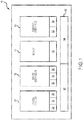
FIG. 1 is a simplified schematic representation of a brazing system according to the inventive arrangements, in various embodiments; -
FIG. 2 is a partially perspective view of a brazing system, in various embodiments; -
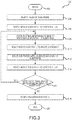
FIG. 3 is a flow chart of a brazing method, in various embodiments; -
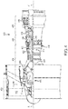
FIG. 4 is a simplified cross-sectional side view of an exemplary gas turbine engine, in various embodiments; and -
FIG. 5 depicts a representative substrate, in various embodiments. - This detailed description of exemplary embodiments references the accompanying drawings, which show exemplary embodiments by way of illustration. While these exemplary embodiments are described in sufficient detail to enable those skilled in the art to practice this disclosure, it should be understood that other embodiments may be realized and that logical changes and adaptations in construction and design may be made in accordance with this disclosure and the teachings described herein without departing from the scope of this disclosure. Thus, this detailed description is presented for purposes of illustration only and not of limitation.
- In accordance with various aspects of this disclosure, systems and methods are described for applying a braze material to a substrate. For example, a braze material can be applied to a combustion liner of gas turbine engine, such as one configured for use in an aerospace application.
- Referring now to
FIGS. 1-2 and/or in various embodiments, abrazing system 10 comprises avision system 20, abraze dispenser 30, arobot 40, and/or acontrol interface 50. In various embodiments, the brazing system also comprises a processing module 60-e.g., a microprocessor and a tangible, non-transitory memory-in electrical and/or RF communication with thevision system 20, thebraze dispenser 30, therobot 40, and/or thecontrol interface 50. - Referring to
FIG. 1 , and/or in various embodiments, thevision system 20 includes acamera 22, asensor 24, and avision processor module 26 comprising a processor and a tangible, non-transitory memory, each configured to operate together to recognize a region of a substrate to which a braze application is to be made-i.e., to which a braze material is to be applied. In various embodiments, thevision system 20 utilizes thecamera 22 to identify a crack or hole in the substrate to which the braze material is to be applied, such as by identifying an outline of the crack or hole against an expected configuration, such as accessed and/or stored by thevision processor module 26 and/or theprocessing module 60. In various embodiments, thevision system 20 utilizes thesensor 24 andvision processor module 26 to analyze outputs from thecamera 22 to detect or determine an outline of the crack or hole into which the braze material is to be flowed. For example, in various embodiments, thecamera 22 obtains an image of the substrate, and thesensor 24 and/orvision processor module 26 determines from that image the outline of the crack or hole by detecting edges of the crack or hole and areas adjoining and/or around the crack or hole to determine the region of the substrate to which the braze material is to be applied. For example, in various embodiments, thesensor 24 senses the surface of the substrate, and thevision processor module 26 analyzes output(s) from thecamera 22 and/orsensor 24 to determine the edges of the crack or hole. In various embodiments, these parameters are stored as a plurality of coordinates as related to the substrate. - If the
vision system 20 is unable to locate all or any cracks or holes on the substrate in need of a braze application, then therobot 40 can default to cooling hole data provided at the control interface and/or programmed into theprocessing module 60, in various embodiments. - In various embodiments, the
camera 22 and/orsensor 24 and/orvision processor module 26 is/are also used to confirm an orientation and/or positon of the substrate prior to applying the braze material. - In various embodiments, the
braze dispenser 30 includes abraze head 32, abraze nozzle 34, and abraze processor module 36 comprising a processor and a tangible, non-transitory memory, each configured to operate together to apply the braze material to the region of the substrate determined and/or identified by thevision system 20. In various embodiments, the braze material applied by thebraze head 32 andbraze nozzle 34 is a function of the substrate material. For example, in various embodiments, the braze material is an elemental material and/or metal-such as, for example, aluminum, boron, chromium, cobalt, copper, gold, hafnium, iron, magnesium, molybdenum, nickel, palladium, rhenium, silicon, silver, tantalum, tin, titanium, tungsten, zinc, zirconium, etc. In various embodiments, the braze material is an amalgamation, alloy, and/or superalloy of various materials and/or metals-such as, for example, various combinations of aluminum, boron, chromium, cobalt, copper, gold, hafnium, iron, magnesium, molybdenum, nickel, palladium, rhenium, silicon, silver, tantalum, tin, titanium, tungsten, zinc, zirconium, and/or other additives or adjuncts. In various embodiments, adhesive materials are added to the braze material to obtain desired properties thereof. In various embodiments, binder materials are added to the braze material to obtain desired properties thereof. In various embodiments, carrier materials are added to the braze material to obtain desired properties thereof. In various embodiments, filler materials are added to the braze material to obtain desired properties thereof. - In various embodiments, the
braze dispenser 30 works with braze materials that are in coating, foil, liquid, paste, putty, slurry, solid (e.g., powdered), and/or tape forms. - In various embodiments, the braze material is brought to and/or held at a temperature above the melting temperature of the braze material, but below the melting temperature of the metals or materials being joined (i.e., the substrate), such as above or below 842 degrees Fahrenheit (450 degrees Celsius), in various applications. For example, in various embodiments, the
braze nozzle 34 is positioned proximate and/or held above a surface of the substrate to be joined and the temperature of the braze material is raised to and/or held at or above the melting temperature of the braze material (e.g., the braze temperature), but below the melting temperature of the substrate. The braze material thus becomes molten, wets adjacent surfaces of the substrate when applied thereto, and, through capillary action, is drawn into and fills in gaps in the substrate, in various embodiments. In various embodiments, the braze material cools and/or is cooled, by which the braze material solidifies and forms a strong metallurgical bond with the substrate at a brazement joint. In various embodiments, bonding occurs at molecular levels of the braze material and/or substrate. In various embodiments, the brazement joint provides a desired degree of serviceability under various temperatures, stresses, vibration loads, etc. In various embodiments, the braze joint is superior to the original substrate in various aspects. - In various embodiments, the
vision system 20 is used to orient and/or confirm the orientation of the substrate prior to the braze application. - In various embodiments, the
vision system 20 is used to inspect the braze application before, during, and/or after the braze application is completed. - In various embodiments, the braze process is repeated one or more times.
- In various embodiments, the
vision system 20 is used to determine if the braze process should be and/or is repeated one or more times. - In various embodiments, the
braze dispenser 30 is controlled to apply an amount of braze material to the crack or hole corresponding to an amount and/or location as determined by thevision system 20 regarding the substrate. - In various embodiments, the
vision system 20 is used to determine if the substrate should be and/or is subjected to a follow-up braze removal technique-e.g., grinding-following the braze application to remove any excess braze that may have occurred during the brazing application. - In various embodiments, the
robot 40 includes anarticulating arm 42 configured to gather, hold, move, pick, position, and/or release the substrate, including proximate and/or under thevision system 20 and/or thebraze dispenser 30. - In various embodiments, the articulating
arm 42 is configured to be movable according to a plurality of coordinate axes within and/or defined by thebrazing system 10. - In various embodiments, the
robot 40 is configured to be movable so that an operator operating thecontrol interface 50 can manipulate and/or view the substrate within thebrazing system 10. - In various embodiments, the articulating
arm 42 is configured to be movable so that an operator operating thecontrol interface 50 can manipulate and/or view the substrate within thebrazing system 10. - In various embodiments, the articulating
arm 42 is configured to be movable so that thevision system 20 inspects the substrate from multiple angles, axes, orientations, and/or views. For instance, the portion(s) of the substrate in need of brazing may be present in any number of locations and/or surfaces of the component. In addition, the portion(s) of the substrate in need of brazing may be present in any number of sizes and shapes on the component, in various embodiments. - In various embodiments, the articulating arm is the only and/or primary part of the
brazing system 10 that moves, thevision system 20 and brazedispenser 30 otherwise being stationary, in various embodiments. - In various embodiments, the
control interface 50 includes aninput device 52 and anoutput device 54, configured to interact with and/or operate thebrazing system 10. For example, in various embodiments, theinput device 52 comprises, for example, a keyboard, mouse, touch screen, etc. for inputting commands, directions, instructions, and/or the like to thebrazing system 10. In various embodiments, theinput device 52 is configured to allow an operator to control thevision system 20, thebraze dispenser 30, and/or therobot 40. In various embodiments, theoutput device 54 comprises, for example, a display. In various embodiments, theoutput device 54 is configured to allow the operator to view images from thevision system 20. - In various embodiments, the
control interface 50 of thebrazing system 10 is configured to allow an operator to control and/or positon thevision system 20, thebraze dispenser 30, and/or therobot 40. - In various embodiments, the
control interface 50 is configured to allow an operator to control movement, orientation, and/or position of the substrate that therobot 40 brings to thebrazing system 10, including proximate to thevision system 20 and/or brazedispenser 30. - In various embodiments, the
control interface 50 is configured to allow the operator to control thebraze head 32 and brazenozzle 34 through thebraze processor module 36. For example, in various embodiments, an operator can control the type of braze material flowing through thebraze dispenser 30. In various embodiments, an operator can control the flow rate of the braze material flowing through thebraze dispenser 30, such as monitoring and/or controlling a flow rate of the braze material through thebraze nozzle 34. - In various embodiments, a flow rate of the braze material through the
braze nozzle 34 is approximately 0.011 - 0.11 pounds (5 - 50 grams) per minute, such as approximately 0.055 pounds (25 grams) per minute. - In various embodiments, an application rate of the braze material through the
braze nozzle 34 is approximately 0.008 - 0.016 inches (0.2 - 0.4 millimeters) per pass, such as approximately 0.012 inches (0.3 millimeters) per pass. - In various embodiments, a thickness of the applied braze material is at least 0.01 inches (0.254 millimeters). For example, in various embodiments, a thickness of the applied braze material is approximately 0.01 - 0.06 inches (0.254 - 1.524 millimeters), such as approximately 0.035 inches (0.9 mm).
- In various embodiments, the
braze nozzle 34 does not contact the substrate, but instead stays a suitable distance from the substrate when the braze material is being dispensed. For example, in various embodiments, the braze dispenser applies the braze material at a distance of approximately 0.049 - 0.059 inches (1.25 - 1.5 millimeters) away from the substrate, such as approximately 0.054 inches (1.372 mm) away from the substrate. - In various embodiments, the
processing module 60 of thebrazing system 10 communicates with and controls thevision system 20, thebraze dispenser 30, therobot 40, and/or thecontrol interface 50, as described herein. More specifically, theprocessing module 60, in various embodiments, includes one or more controllers 62 (e.g., processors) and one or more tangible,non-transitory memories 64 capable of implementing digital or programmatic logic. In various embodiments, for example, the one ormore controllers 62 are one or more of an application specific integrated circuit (ASIC), digital signal processor (DSP), field programmable gate array (FPGA), general purpose processor, and/or other programmable logic device, discrete gate, transistor logic, or discrete hardware components, or any various combinations thereof or the like, and the one ormore memories 64 store instructions that are implemented by the one ormore controllers 62 for performing various functions, such as controlling thebrazing system 10 as described herein. As such, thebrazing system 10 is, in various embodiments, an auto-adaptive brazing dispensing system operative in response to various control and/or electronic signals. In various embodiments, thebrazing system 10 operates in an automated and/or semi-automated fashion. - In various embodiments, the
brazing system 10 is configured to only operate if a locking mechanism is engaged, such as a closing and/or locking a door of thebrazing system 10 before and/or during a brazing application. - In various embodiments, the
brazing system 10 is configured to only operate if the substrate is loaded into thebrazing system 10 in a predetermined way. For example, in various embodiments, therobot 40 is configured to only operate if the substrate is loaded into thebrazing system 10 in a predetermined way. If the substrate is not loaded into thebrazing system 10 in a predetermined way, then thebrazing system 10,braze dispenser 30, and/orrobot 40 are configured to not operate, in various embodiments. - In various embodiments, the
brazing system 10 is programmed to know the number of substrates to which a brazing application is to be made. - In various embodiments, the vision system is programmed to recognize different types of substrates.
- In various embodiments, the
brazing system 10 is programmed to make different brazing applications to different substrates and/or different types of substrates. - In various embodiments, the
robot 40 is configured to not make an incorrect braze application to a particular substrate. - In various embodiments, the
brazing system 10 is configured to operate only if an expected substrate is recognized by thevision system 20 and/or configured to not operate without a substrate being within thebrazing system 10. - In various embodiments, the
brazing system 10 is configured to only make a braze application at a specified location on the substrate and/or to not make a braze application at an unspecified location on the substrate. - In various embodiments, the
braze dispenser 30 is programmed to apply a predetermined braze material at a predetermined location, to apply a predetermined mass of a braze material at a predetermined location, to operate with a particular density of braze material, to operate with a predetermined end effector to apply the braze, to operate with a predetermined braze material deposition rate, to perform a self-test and/or periodic self-tests on a sample substrate, etc. - Referring now to
FIG. 3 , amethod 300 begins at astep 302. Thereafter, a robot picks up a substrate at a step 304-such as picking up a fixture holding a substrate preloaded into the fixture, in various embodiments. Thereafter, the robot moves the substrate to a vision system at a step 306-such as moving the substrate to within operable proximity of the vision system. Thereafter, the vision system determines where to apply a braze material to the substrate at a step 308-such as by identifying cracks or holes of the substrate by comparison against expected parameters. Thereafter, the robot moves the substrate to a braze dispenser at a step 310-such as moving the substrate to within operable proximity of the braze dispenser. Thereafter, the braze dispenser applies a braze material to the substrate at a step 312-such as applying the braze material to the substrate in the amounts and/or at the locations identified by the vision system. Thereafter, the robot moves the substrate to the vision system at a step 314-such as moving the substrate back to within operable proximity of the vision system. Thereafter, the vision system identifies if additional and/or more braze material should be applied to the substrate at astep 316. If additional and/or more braze material should be applied to the substrate, themethod 300 returns control to step 308 atstep 316. Otherwise, the robot releases the substrate at astep 318 following step 316-such as discharging the substrate from the robot. Thereafter, themethod 300 ends at astep 320. - Referring now to
FIG. 4 , a representativegas turbine engine 420 is a two-spool turbofan that incorporates afan section 422, acompressor section 424, acombustor section 426, and aturbine section 428. In various embodiments, thegas turbine engine 420 includes other systems and features too. - In various embodiments, the
fan section 422 is positioned towards a front or inlet of thegas turbine engine 420, and it includes afan 442 that induces air from a surrounding environment into thegas turbine engine 420 and accelerates a portion of the air towards thecompressor section 424. - In various embodiments, the
fan section 422 drives the air along a bypass flowpath B while thecompressor section 424 drives the air along a core flowpath C for acceleration, compression, and communication into thecombustor section 426, then expansion through theturbine section 428. - In various embodiments, the
compressor section 424 raises the pressure of the air received from thefan section 422 to a relatively high level. The compressed air from thecompressor section 424 then enters thecombustor section 426, where one or more fuel nozzles inject fuel into the compressed air. The fuel-air mixture is ignited in thecombustor section 426 to generate combustion gases. The high-energy combustion gases from thecombustor section 426 then flow into and through theturbine section 428, thereby causing rotationally mounted turbine blades to rotate and generate energy. The air exiting theturbine section 428 is exhausted from thegas turbine engine 420 via an exhaust section. - In various embodiments, the
gas turbine engine 420 includes one or more of a low pressure compressor (LPC) 444, a high pressure compressor (HPC) 452, a high pressure turbine (HPT) 454, and/or a low pressure turbine (LPT) 446. - In various embodiments, the
gas turbine engine 420 is or includes other types of engines, such as turbojets, turboshafts, three-spool (plus fan) turbofans, and/or direct drive turbofans. In various embodiments, an intermediate spool includes an intermediate pressure compressor (not shown) between theLPC 444 and theHPC 452 and/or an intermediate pressure turbine (not shown) between theHPT 454 and theLPT 446. - In various embodiments, the
gas turbine engine 420 includes alow spool 430 and ahigh spool 432 mounted for rotation about an engine central longitudinal axis A - A' relative to an engine static structure orengine case 436 via multiple bearing structures. In various embodiments, thelow spool 430 includes aninner shaft 440 that interconnects thefan 442 of thefan section 422, theLPC 444 of thecompressor section 424, and theLPT 446 of theturbine section 428. In various embodiments, theinner shaft 440 communicates with thefan 442 directly or through a gearedarchitecture 448 to drive thelow spool 430 at a higher speed than thefan 442. In various embodiments, a reduction transmission is an epicyclic transmission, such as a planetary or star gear system. - In various embodiments, the
high spool 432 includes anouter shaft 450 that interconnects theHPC 452 of thecompressor section 424 and theHPT 454 of theturbine section 428. In various embodiments, acombustion chamber 456 is arranged between theHPC 452 and theHPT 454. In various embodiments, theinner shaft 440 and theouter shaft 450 are concentric and rotate about the engine central longitudinal axis A - A' that is collinear with their longitudinal axes. Core airflow flowing along core flowpath C is compressed by theLPC 444, further compressed by theHPC 452, mixed with fuel, burned in thecombustion chamber 456, and then expanded over theHPT 454 and theLPT 446. In various embodiments, theHPT 454 and theLPT 446 rotationally communicate with thehigh spool 432 and thelow spool 430, respectively, in response to the expansion. - In various embodiments, the
gas turbine engine 420 is a high-bypass geared aircraft engine. In various embodiments, thegas turbine engine 420 bypass ratio is greater than approximately 6:1. In various embodiments, the gearedarchitecture 448 includes an epicyclic gear train, such as a planetary gear system or other gear system. In various embodiments, the example epicyclic gear train has a gear reduction ratio of greater than approximately 2.3:1, and, in other embodiments, it is greater than approximately 2.5:1. In various embodiments, the geared turbofan enables operation of thelow spool 430 at higher speeds that can increase the operational efficiency of theLPC 444 and theLPT 446 and render increased pressure in a fewer number of stages. - A pressure ratio associated with the
LPT 446 is pressure measured prior to the inlet of theLPT 446 as related to the pressure at the outlet of theLPT 446 prior to an exhaust nozzle of thegas turbine engine 420. In various embodiments, the bypass ratio of thegas turbine engine 420 is greater than approximately 10:1, thefan 442 diameter is significantly larger than that of theLPC 444, and theLPT 446 has a pressure ratio that is greater than approximately 5:1. - In various embodiments, a significant amount of thrust is provided by the bypass flowpath B due to the high bypass ratio. In various embodiments, the
fan section 422 is suited for a particular flight condition-e.g., cruising at approximately 0.8 Mach and/or approximately 35,000 feet (10,668 meters). This flight condition, with thegas turbine engine 420 at a preferred fuel consumption, is known as thrust specific fuel consumption (TSFC), which is an industry-standard parameter of fuel consumption per unit of thrust. - Fan pressure ratio is a pressure ratio across a blade of the
fan 442 in thefan section 422 without using a fan exit guide vane system. In various embodiments, a low fan pressure ratio of thegas turbine engine 420 is less than 1.45. A low corrected fan tip speed is the actual fan tip speed divided by an industry-standard temperature correction of (T/518.7)0.5, in which T is an ambient temperature measurement in degrees Rankine. In various embodiments, the low corrected fan tip speed of thegas turbine engine 420 is less than approximately 1,150 feet (351 meters) per second. - In various embodiments, the
combustion chamber 456 contains the combustion products that flow axially toward theturbine section 428. In various embodiments, an outer wall and/or an inner wall are generally cylindrical and extend circumferentially about the engine central longitudinal axis A - A'. In various embodiments, one or more of the outer wall and/or the inner wall are formed utilizing shells and panels. In various embodiments, the shells and/or panels are circumferentially continuous (e.g., ring shaped) and divided axially, divided circumferentially from each, and/or both (e.g., substantially rectilinear in shape). - In various embodiments, the inventive arrangements can be applied to any of the aforementioned engine components, including, for example, airfoils, blades, buckets, combustors, nozzles, shrouds, vanes, walls, etc.
- Referring now to
FIG. 5 , arepresentative substrate 500 is depicted, which can be a component of a gas turbine engine, such as depicted inFIG. 4 , to which a braze application is to be made. For example, thesubstrate 500 could be on airfoil, related to platform holes of a vane structure, etc. In various embodiments, thesubstrate 500 is carried on a holdingtray 502 or the like for transportation by therobot 40 ofFIGS. 1-2 to and/or within thevision system 20 ofFIGS 1-2 . In various embodiments, the holding tray 502 (or substrate 500) includes anidentifier 504 such as a bar code or the like that thevision system 20 ofFIGS. 1-2 is programmed to recognize. - Technical benefits and effects of this disclosure include providing braze dispensing systems and methods for applying a braze material to a substrate, such as from a gas turbine engine, an aircraft gas turbine engine, etc., to improve the usability and/or re-usability thereof, including if a substrate has a crack or hole, allowing a flowed braze material to meet or exceed quality and/or standards of the component following the braze application, thereby reducing production costs, allowing re-works, extending the working life of various components, etc.
- Advantages, benefits, and/or solutions to problems have been described herein with regard to specific embodiments. Furthermore, connecting lines shown in the various figures contained herein are intended to represent exemplary functional relationships and/or physical couplings between the various elements. It should be noted that many additional and/or functional relationships or physical connections may be present in a practical system. However, the advantages, benefits, and/or solutions to problems, and any elements that may cause any advantage, benefit, and/or solution to occur or become more pronounced are not to be construed as critical, essential, and/or required elements or features of this disclosure.
- The scope of this disclosure is accordingly to be limited by nothing other than the appended claims, in which reference to an element in the singular is not intended to mean "one and only one" unless explicitly so stated, but rather "one or more." It is to be understood that unless specifically stated otherwise, references to "a," "an," and/or "the" may include one or more than one, and that reference to an item in the singular may also include the item in the plural, and vice-versa. All ranges and ratio limits disclosed herein may be combined.
- Moreover, where a phrase similar to "at least one of A, B, and C" is used in the claims, it is intended that the phrase be interpreted to mean that A alone may be present in an embodiment, B alone may be present in an embodiment, C alone may be present in an embodiment, or that any combination of the elements A, B, and C may be present in a single embodiment; for example, A and B, A and C, B and C, or A and B and C. Different cross-hatching is used throughout the figures to denote different parts, but not necessarily to denote the same or different materials. Like depictions and/or numerals also generally represent like elements.
- The steps recited in any of the method or process descriptions may be executed in any order and are not necessarily limited to the order presented. Furthermore, any reference to singular elements, embodiments, and/or steps includes plurals thereof, and any reference to more than one element, embodiment, and/or step may include a singular one thereof. Elements and steps in the figures are illustrated for simplicity and clarity and have not necessarily been rendered according to any particular sequence. For example, steps that may be performed concurrently or in different order are only illustrated in the figures to help to improve understanding of embodiments of the present, representative disclosure.
- Any reference to attached, fixed, connected, or the like may include permanent, removable, temporary, partial, full and/or any other possible attachment option. Additionally, any reference to without contact (or similar phrases) may also include reduced contact or minimal contact. Surface shading lines may be used throughout the figures to denote different parts or areas, but not necessarily to denote the same or different materials. In some cases, reference coordinates may or may not be specific to each figure.
- Systems, methods, and apparatus are provided herein. In the detailed description herein, references to "one embodiment," "an embodiment," "various embodiments," etc., indicate that the embodiment described may include a particular characteristic, feature, and/or structure, but every embodiment may not necessarily include this particular characteristic, feature, and/or structure. Moreover, such phrases are not necessarily referring to the same embodiment. Further, when a particular characteristic, feature, and/or structure is described in connection with an embodiment, it is submitted that it is within the knowledge of one skilled in the art to affect such characteristic, feature, and/or structure in connection with other embodiments, whether or not explicitly described. After reading the description, it will be apparent to one skilled in the relevant art(s) how to implement this disclosure in alternative embodiments.
- Furthermore, no component, element, or method step in the present disclosure is intended to be dedicated to the public regardless of whether the component, element, or method step is explicitly recited in the claims. No claim element is intended to invoke 35 U.S.C. § 112(f) unless the element is expressly recited using the phrase "means for." As used herein, the terms "comprises," "comprising," or any other variation thereof, are intended to cover a non-exclusive inclusion, such that an apparatus, article, method, and/or process, method that comprises a list of elements does not include only those elements, but it may also include other elements not expressly listed or inherent to such apparatus, article, method, and/or process.
Claims (15)
- A brazing system, comprising:a vision system having a camera, a sensor, and a vision processor module;a braze dispenser having a braze head, a braze nozzle, and a braze processor module;a robot having an articulating arm;a control interface having an input device and an output device; anda processing module having a controller and memory configured to communicate with and control the vision system, the braze dispenser, the robot, and the control interface;wherein the vision system is configured to determine where the braze dispenser is to apply a braze material to a substrate and whether the braze dispenser is to apply additional braze material to the substrate after an initial application.
- The brazing system of claim 1, wherein the processing module is configured to receive commands from the input device to communicate with and control the vision system, the braze dispenser, and the robot.
- The brazing system of claim 2, wherein the processing module is configured to communicate with and control the articulating arm of the robot.
- The brazing system of claim 3, wherein the processing module is configured to communicate with and control the articulating arm of the robot to place the substrate proximate the vision system.
- The brazing system of claim 3, wherein the processing module is configured to communicate with and control the articulating arm of the robot to place the substrate proximate the braze dispenser.
- The brazing system of any preceding claim, wherein the processing module is configured to communicate with and control the braze dispenser to apply the braze material to the substrate based on determinations from the vision system.
- The brazing system of any preceding claim, wherein the substrate is a component of a gas turbine engine.
- The brazing system of claim 7, wherein the gas turbine engine is configured for use in an aircraft.
- An automated method of applying a braze material to a substrate, comprising:moving the substrate to a vision system using a robot;using the vision system to make a first determination where the braze material is to be applied to the substrate;moving the substrate to a braze dispenser using the robot;applying the braze material to the substrate using the braze dispenser based on the first determination from the vision system; andusing the vison system to make a second determination whether to apply additional braze material to the substrate.
- The automated method of claim 9, wherein the braze dispenser applies the braze material to the substrate at approximately 0.011 - 0.11 pounds (5 - 50 grams) per minute.
- The automated method of claim 9 or 10, wherein the braze dispenser applies the braze material to the substrate at approximately 0.008 - 0.016 inches (0.2 - 0.4 millimeters) per pass.
- The automated method of claim 9, 10 or 11, wherein a thickness of the applied braze material is approximately 0.01 - 0.06 inches (0.254 - 1.524 millimeters).
- The automated method of any of claims 9 to 12, wherein the braze dispenser applies the braze material to the substrate at a distance of approximately 0.049 - 0.059 inches (1.25 - 1.5 millimeters) away from the substrate.
- The automated method of any of claims 9 to 13, wherein the substrate is a component of a gas turbine engine.
- The automated method of claim 14, wherein the gas turbine engine is configured for use in an aircraft.
Applications Claiming Priority (1)
| Application Number | Priority Date | Filing Date | Title |
|---|---|---|---|
| US15/963,230 US10780515B2 (en) | 2018-04-26 | 2018-04-26 | Auto-adaptive braze dispensing systems and methods |
Publications (2)
| Publication Number | Publication Date |
|---|---|
| EP3578284A1 true EP3578284A1 (en) | 2019-12-11 |
| EP3578284B1 EP3578284B1 (en) | 2021-12-01 |
Family
ID=66286270
Family Applications (1)
| Application Number | Title | Priority Date | Filing Date |
|---|---|---|---|
| EP19171181.1A Active EP3578284B1 (en) | 2018-04-26 | 2019-04-25 | Auto-adaptive braze dispensing system and method |
Country Status (2)
| Country | Link |
|---|---|
| US (2) | US10780515B2 (en) |
| EP (1) | EP3578284B1 (en) |
Families Citing this family (1)
| Publication number | Priority date | Publication date | Assignee | Title |
|---|---|---|---|---|
| CN111069728B (en) * | 2019-12-12 | 2021-11-05 | 深圳先进技术研究院 | Online soldering visual servo control method and system |
Citations (4)
| Publication number | Priority date | Publication date | Assignee | Title |
|---|---|---|---|---|
| JPS62173076A (en) * | 1986-01-22 | 1987-07-29 | Sumitomo Electric Ind Ltd | Method for soldering by laser |
| JP2008045956A (en) * | 2006-08-11 | 2008-02-28 | Okayama Univ | Soldering inspection method, solder bonding method, and solder bonding apparatus |
| US20150289426A1 (en) * | 2012-11-19 | 2015-10-08 | Panasonic Intellectual Property Management Co., Ltd. | Electronic component mounting system |
| US20160144465A1 (en) * | 2013-07-12 | 2016-05-26 | United Technologies Corporation | Repair or remanufacture of combustor liner panels with an oxidation resistant braze |
Family Cites Families (109)
| Publication number | Priority date | Publication date | Assignee | Title |
|---|---|---|---|---|
| USRE24020E (en) * | 1955-06-14 | Auto body repairing tool | ||
| US2651276A (en) * | 1951-01-10 | 1953-09-08 | Emil A Kristen | Auto body repairing tool |
| US3525151A (en) * | 1966-03-29 | 1970-08-25 | Accumulateurs Fixes | Process for automatically making electric batteries |
| US3497951A (en) * | 1967-11-01 | 1970-03-03 | Ite Imperial Corp | Bus-bar joints and methods for producing them |
| US3680762A (en) * | 1969-06-28 | 1972-08-01 | Kenshi Kondo | Automatic soldering apparatus |
| USRE35098E (en) * | 1979-12-20 | 1995-11-28 | Modine Manufacturing Co. | Method of making a heat exchanger |
| US4377024A (en) * | 1981-04-02 | 1983-03-22 | Modine Manufacturing Company | Method of making a heat exchanger |
| EP0078900B1 (en) * | 1981-10-22 | 1985-03-20 | Siemens-Albis Aktiengesellschaft | Device for the dispersion of a solder layer on a printed-circuit board |
| US4530456A (en) * | 1983-05-04 | 1985-07-23 | Ppg Industries, Inc. | Method and apparatus for soldering by means of an industrial robot |
| US4796560A (en) * | 1984-03-06 | 1989-01-10 | Northern Telecom Limited | Automatic solder paste application to circuit boards |
| US4704305A (en) * | 1984-03-06 | 1987-11-03 | Northern Telecom Limited | Automatic solder paste application to circuit boards |
| US4703558A (en) * | 1986-02-18 | 1987-11-03 | Maekinen Matti | Assembly system |
| US4832250A (en) * | 1987-05-28 | 1989-05-23 | Srtechnologies, Inc. | Electronic circuit board rework and repair system |
| JPH07109935B2 (en) * | 1989-01-27 | 1995-11-22 | オムロン株式会社 | Method and apparatus for automatically correcting solder defects |
| IT1232117B (en) * | 1989-06-23 | 1992-01-23 | Sapri Spa | AUTOMATIC WELDING BRAZING MACHINE |
| US4928387A (en) * | 1989-09-07 | 1990-05-29 | Rockwell International Corp. | Temporary soldering aid for manufacture of printed wiring assemblies |
| DE3939812C2 (en) * | 1989-12-01 | 1993-11-11 | Deutsche Aerospace | Laser soldering system for SMD elements |
| WO1993009654A1 (en) * | 1991-11-07 | 1993-05-13 | Omron Corporation | Automatic soldering apparatus, teaching apparatus thereof and teaching method thereof, soldering inspection apparatus and its inspection method, and automatic soldering correction apparatus and its correction method |
| GB9126530D0 (en) * | 1991-12-13 | 1992-02-12 | Spirig Ernest | Soldering device |
| JPH06292964A (en) * | 1992-07-22 | 1994-10-21 | A Tec Tekutoron Kk | Automatic soldering device |
| US5303824A (en) * | 1992-12-04 | 1994-04-19 | International Business Machines Corporations | Solder preform carrier and use |
| JP3583462B2 (en) * | 1993-04-05 | 2004-11-04 | フォード モーター カンパニー | Micro soldering apparatus and method for electronic components |
| US5297716A (en) * | 1993-04-12 | 1994-03-29 | Honeywell Inc. | Soldering tool with attached thermocouple |
| KR950010725A (en) * | 1993-09-22 | 1995-04-28 | 김광호 | Automatic Soldering Equipment |
| US5411897A (en) * | 1994-02-04 | 1995-05-02 | Mobil Solar Energy Corporation | Machine and method for applying solder paste to electronic devices such as solar cells |
| US5437737A (en) | 1994-02-07 | 1995-08-01 | United Technologies Corporation | Repair coating for superalloy articles, such as gas turbine engine components |
| US5525777A (en) * | 1994-08-19 | 1996-06-11 | Allen-Bradley Company, Inc. | Apparatus and method for flexible point-to-point soldering |
| US5500512A (en) * | 1994-12-16 | 1996-03-19 | General Electric Company | Welding wire verification control system |
| US5620927A (en) * | 1995-05-25 | 1997-04-15 | National Semiconductor Corporation | Solder ball attachment machine for semiconductor packages |
| US6543129B2 (en) * | 1995-11-03 | 2003-04-08 | Teka Interconnections Systems, Inc. | Solder-bearing contacts and method of manufacture thereof and use in a solder ball grid array connector |
| US5806751A (en) * | 1996-10-17 | 1998-09-15 | United Technologies Corporation | Method of repairing metallic alloy articles, such as gas turbine engine components |
| US5878911A (en) * | 1997-06-23 | 1999-03-09 | Industrial Technology Research Institute | Solder-ball supplying apparatus |
| US6199746B1 (en) * | 1999-08-02 | 2001-03-13 | General Electric Company | Method for preparing superalloy castings using a metallurgically bonded tapered plug |
| ATE487238T1 (en) * | 1999-09-29 | 2010-11-15 | Kaneka Corp | METHOD AND DEVICE FOR AUTOMATICALLY SOLDERING A CONNECTION WIRE TO A SOLAR CELL BATTERY |
| MY124946A (en) * | 2000-10-23 | 2006-07-31 | Senju Metal Industry Co | Automatic wave soldering apparatus and method |
| US6405918B1 (en) | 2000-10-30 | 2002-06-18 | Trw Inc. | Mechanical retention system for braze and solder joints |
| US6369359B1 (en) * | 2000-11-08 | 2002-04-09 | Terry H. Morrison | Self-feeding soldering device |
| US6530971B1 (en) | 2001-01-29 | 2003-03-11 | General Electric Company | Nickel-base braze material and braze repair method |
| US6575349B2 (en) | 2001-02-22 | 2003-06-10 | Hickham Industries, Inc. | Method of applying braze materials to a substrate |
| EP1275461A1 (en) * | 2001-07-11 | 2003-01-15 | Taga Manufacturing Co., Ltd., 14-1 | Brazing method and device, relay coil and method for the coil by the brazing method and device |
| JP4371619B2 (en) * | 2001-09-21 | 2009-11-25 | パナソニック株式会社 | Reflow device |
| EP1312437A1 (en) * | 2001-11-19 | 2003-05-21 | ALSTOM (Switzerland) Ltd | Crack repair method |
| KR100443987B1 (en) * | 2002-02-14 | 2004-08-09 | 삼성전자주식회사 | Soldering apparatus for collimator and soldering method thereof |
| US7632750B2 (en) * | 2006-07-07 | 2009-12-15 | Semigear Inc | Arrangement for solder bump formation on wafers |
| US7108755B2 (en) * | 2002-07-30 | 2006-09-19 | Motorola, Inc. | Simplification of ball attach method using super-saturated fine crystal flux |
| NL1022515C2 (en) * | 2003-01-29 | 2004-08-03 | Vitronics Soltec B V | Device and method for corrective soldering. |
| US7663073B2 (en) * | 2003-05-13 | 2010-02-16 | Panasonic Corporation | Optical processing apparatus |
| US7419085B2 (en) * | 2003-05-13 | 2008-09-02 | Matsushita Electric Industrial Co., Ltd. | Optical processing apparatus |
| TWI235262B (en) * | 2003-11-27 | 2005-07-01 | Ind Tech Res Inst | Device and method for automatically assembling optical components |
| KR100586522B1 (en) * | 2004-03-17 | 2006-06-07 | 삼성전자주식회사 | Printed Circuit Board Processing System |
| WO2005118196A1 (en) * | 2004-06-01 | 2005-12-15 | Soutec Soudronic Ag | Hard-soldering method and device |
| JP4488830B2 (en) * | 2004-08-03 | 2010-06-23 | 株式会社東芝 | Regeneration treatment method of gas turbine stationary blade |
| US7320205B2 (en) * | 2005-02-02 | 2008-01-22 | Tvi Corporation | Method for manufacturing filter canisters and tracking quality assurance |
| US20060219330A1 (en) * | 2005-03-29 | 2006-10-05 | Honeywell International, Inc. | Nickel-based superalloy and methods for repairing gas turbine components |
| US7628871B2 (en) * | 2005-08-12 | 2009-12-08 | Intel Corporation | Bulk metallic glass solder material |
| WO2007039428A1 (en) * | 2005-09-23 | 2007-04-12 | Assa Abloy Identification Technologies Gmbh | Monitoring apparatus and method for monitoring a joining process and for retracing quality |
| JP4724224B2 (en) * | 2006-03-30 | 2011-07-13 | 富士通株式会社 | Method for manufacturing solder bonded product, solder bonding apparatus, reflow apparatus, and solder bonding method |
| DE102006026134A1 (en) * | 2006-06-03 | 2007-06-21 | Daimlerchrysler Ag | Workpiece e.g. vehicle body shell, processing system, has workpiece support unit, and industrial robot couplable at support unit, where control unit of robot and/or production unit are arranged on support device |
| DE102006026132A1 (en) * | 2006-06-03 | 2007-06-21 | Daimlerchrysler Ag | Handling system for moving work piece e.g. vehicle body, has industrial robot, where drive unit is not operated on supporting device and supporting device is moved through carrier unit by suspension system in coupled position of robot |
| US20080083816A1 (en) * | 2006-10-04 | 2008-04-10 | Leinbach Glen E | Statistical process control of solder paste stenciling using a replicated solder paste feature distributed across a printed circuit board |
| US7555359B2 (en) * | 2006-10-06 | 2009-06-30 | Hitachi, Ltd | Apparatus and method for correcting defects by friction stir processing |
| US20080179298A1 (en) * | 2007-01-29 | 2008-07-31 | Tdk Corporation | Method of detecting an object to be detected in a joining device, joining device, and joining method |
| US7710611B2 (en) * | 2007-02-16 | 2010-05-04 | Illinois Tool Works, Inc. | Single and multi-spectral illumination system and method |
| US7549568B1 (en) * | 2008-03-20 | 2009-06-23 | Powertech Technology Inc. | Method of forming identification code for wire-bonding machines |
| US9618168B1 (en) * | 2014-09-28 | 2017-04-11 | Jiaxing Super Lighting Electric Appliance Co., Ltd | LED tube lamp |
| US8355815B2 (en) * | 2009-02-12 | 2013-01-15 | Baker Hughes Incorporated | Methods, systems, and devices for manipulating cutting elements for earth-boring drill bits and tools |
| JP5294916B2 (en) * | 2009-02-17 | 2013-09-18 | パナソニック株式会社 | Laser soldering equipment |
| US8087861B2 (en) * | 2009-05-13 | 2012-01-03 | Kuo-Chung Wang | Plate member fastener |
| EP2299501A1 (en) * | 2009-09-16 | 2011-03-23 | 3S Industries AG | Method and apparatus for providing a solar cell with a solder ribbon |
| US8141766B1 (en) * | 2010-09-06 | 2012-03-27 | Cheng Uei Precision Industry Co., Ltd. | Automatic soldering system |
| DE102011101576A1 (en) * | 2011-05-13 | 2012-11-15 | Mtu Aero Engines Gmbh | Combined heating for soldering a top armor by induction and laser |
| CH705327A1 (en) * | 2011-07-19 | 2013-01-31 | Alstom Technology Ltd | Lot for high-temperature soldering and method of repairing or manufacturing components using this solder. |
| US9452486B2 (en) * | 2011-08-16 | 2016-09-27 | Carrier Corporation | Automatic fluxing machine |
| US20130180107A1 (en) * | 2012-01-15 | 2013-07-18 | Steven Charles Woods | Method for refurbishing a turbo-machine component |
| US9121282B2 (en) * | 2012-02-02 | 2015-09-01 | Honeywell International Inc. | Methods for the controlled reduction of turbine nozzle flow areas and turbine nozzle components having reduced flow areas |
| US9033670B2 (en) * | 2012-04-11 | 2015-05-19 | Honeywell International Inc. | Axially-split radial turbines and methods for the manufacture thereof |
| US10486262B2 (en) * | 2012-07-11 | 2019-11-26 | Carrier Corporation | Method and system for joining workpieces |
| US20140076956A1 (en) * | 2012-09-20 | 2014-03-20 | Tyco Electronics Corporation | Soldering machine and method of soldering |
| HUE039123T2 (en) * | 2012-12-07 | 2018-12-28 | Seho Systemtechnik Gmbh | Method and soldering device for selective soldering with at least one solder nozzle and another functional element which are moved synchronously by a movement device |
| TWM454066U (en) * | 2013-01-25 | 2013-05-21 | Inventec Corp | Automatic welding equipment |
| US8640942B1 (en) * | 2013-03-13 | 2014-02-04 | Siemens Energy, Inc. | Repair of superalloy component |
| US9361682B2 (en) * | 2013-03-15 | 2016-06-07 | John S. Youngquist | Virtual assembly and product inspection control processes |
| EP2837457A1 (en) | 2013-08-13 | 2015-02-18 | Siemens Aktiengesellschaft | A technique for brazing turbomachine components |
| CN104551291A (en) * | 2013-10-21 | 2015-04-29 | 泰科电子(上海)有限公司 | Automatic welding system |
| DE102013112348B4 (en) * | 2013-11-11 | 2024-05-08 | Endress+Hauser SE+Co. KG | Solder application stamp and method for repairing a printed circuit board with at least one defective component |
| US9254537B2 (en) * | 2013-12-19 | 2016-02-09 | Siemens Energy, Inc. | Plural layer putty-powder/slurry application method for superalloy component crack vacuum furnace healing |
| CN106660154A (en) * | 2014-03-25 | 2017-05-10 | 柯马有限责任公司 | Material joint inspection and repair |
| US20170173719A1 (en) * | 2014-08-04 | 2017-06-22 | Ok International, Inc. | Variable temperature controlled soldering iron |
| US9516762B2 (en) * | 2014-08-04 | 2016-12-06 | Ok International Inc. | Soldering iron with automatic soldering connection validation |
| US9724787B2 (en) * | 2014-08-07 | 2017-08-08 | Illinois Tool Works Inc. | System and method of monitoring a welding environment |
| US11103948B2 (en) * | 2014-08-18 | 2021-08-31 | Illinois Tool Works Inc. | Systems and methods for a personally allocated interface for use in a welding system |
| CN115095808A (en) * | 2014-09-28 | 2022-09-23 | 嘉兴山蒲照明电器有限公司 | A LED straight tube light |
| US9746848B2 (en) * | 2014-11-15 | 2017-08-29 | Advanced Simulation Technology, Incorporated | System and method for adaptive positioning of a work piece |
| TWM512880U (en) | 2015-07-03 | 2015-11-21 | Fivetech Technology Inc | Lateral positioning device |
| KR101755464B1 (en) * | 2015-07-31 | 2017-07-07 | 현대자동차 주식회사 | Roof panel press jig for roof laser brazing system |
| KR101713728B1 (en) * | 2015-07-31 | 2017-03-09 | 현대자동차 주식회사 | Brazing assembly for roof laser brazing system |
| KR101703599B1 (en) * | 2015-07-31 | 2017-02-07 | 현대자동차 주식회사 | Roof laser brazing system |
| KR101724469B1 (en) * | 2015-07-31 | 2017-04-07 | 현대자동차 주식회사 | Side panel regular position jig for roof laser brazing system |
| US10065256B2 (en) * | 2015-10-30 | 2018-09-04 | Concept Group Llc | Brazing systems and methods |
| US9966487B2 (en) * | 2015-12-14 | 2018-05-08 | Solarcity Corporation | Strain relief apparatus for solar modules |
| CN108699643B (en) | 2016-02-09 | 2020-06-23 | 日立金属株式会社 | Alloy member, method for producing alloy member, and product using alloy member |
| WO2018025314A1 (en) * | 2016-08-01 | 2018-02-08 | 富士機械製造株式会社 | Soldering device |
| JP6386500B2 (en) * | 2016-08-02 | 2018-09-05 | ファナック株式会社 | Soldering system |
| US10500663B2 (en) * | 2016-08-31 | 2019-12-10 | Siemens Energy, Inc. | Method of tight crack braze repair using acoustics |
| CN206952321U (en) | 2016-11-29 | 2018-02-02 | 贵阳中航动力精密铸造有限公司 | Semi-automatic cored solder applies and puts device |
| CN106984880B (en) | 2017-03-02 | 2019-03-12 | 哈尔滨汽轮机厂有限责任公司 | A kind of stellite linear leaf automatic brazing system and method |
| JP6913350B2 (en) * | 2017-04-28 | 2021-08-04 | 武蔵エンジニアリング株式会社 | Laser soldering method and equipment |
| EP3441180A1 (en) * | 2017-08-11 | 2019-02-13 | General Electric Company | Method of repairing superalloys |
| JP6764394B2 (en) * | 2017-10-02 | 2020-09-30 | 白光株式会社 | Soldering equipment |
-
2018
- 2018-04-26 US US15/963,230 patent/US10780515B2/en active Active
-
2019
- 2019-04-25 EP EP19171181.1A patent/EP3578284B1/en active Active
-
2020
- 2020-08-21 US US17/000,115 patent/US11331739B2/en active Active
Patent Citations (4)
| Publication number | Priority date | Publication date | Assignee | Title |
|---|---|---|---|---|
| JPS62173076A (en) * | 1986-01-22 | 1987-07-29 | Sumitomo Electric Ind Ltd | Method for soldering by laser |
| JP2008045956A (en) * | 2006-08-11 | 2008-02-28 | Okayama Univ | Soldering inspection method, solder bonding method, and solder bonding apparatus |
| US20150289426A1 (en) * | 2012-11-19 | 2015-10-08 | Panasonic Intellectual Property Management Co., Ltd. | Electronic component mounting system |
| US20160144465A1 (en) * | 2013-07-12 | 2016-05-26 | United Technologies Corporation | Repair or remanufacture of combustor liner panels with an oxidation resistant braze |
Also Published As
| Publication number | Publication date |
|---|---|
| US20200384561A1 (en) | 2020-12-10 |
| US11331739B2 (en) | 2022-05-17 |
| US10780515B2 (en) | 2020-09-22 |
| EP3578284B1 (en) | 2021-12-01 |
| US20190329343A1 (en) | 2019-10-31 |
Similar Documents
| Publication | Publication Date | Title |
|---|---|---|
| US11517981B2 (en) | Laser powder deposition weld rework for gas turbine engine non-fusion weldable nickel castings | |
| EP3080401B1 (en) | Bonded multi-piece gas turbine engine component | |
| EP3062953B1 (en) | Laser powder deposition weld rework for gas turbine engine non-fusion weldable nickel castings | |
| EP3415718A2 (en) | Gas turbine engine components with air-cooling features, and related methods of manufacturing the same | |
| US10408061B2 (en) | Article with sections having different microstructures and method therefor | |
| EP3323984B1 (en) | Airfoil with geometrically segmented coating section | |
| EP3351729B1 (en) | Gas turbine engine component and corresponding gas turbine engine | |
| US11331739B2 (en) | Auto-adaptive braze dispensing systems and methods | |
| EP3133251B1 (en) | Blade outer air seal component with varying thermal expansion coefficient | |
| US10132176B2 (en) | Split airfoil cluster and method therefor | |
| EP2943312B1 (en) | Remote feature measurement | |
| US20150308449A1 (en) | Gas turbine engine component with brazed cover | |
| EP3323986B1 (en) | Airfoil with geometrically segmented coating section | |
| EP4545219A1 (en) | Method of operating a laser additive manufacturing machine | |
| EP3323996B1 (en) | Turbine engine component with geometrically segmented coating section and cooling passage | |
| US20160326892A1 (en) | Ceramic covered turbine components | |
| EP3421729A1 (en) | Alumina seal coating with interlayer | |
| US10744557B2 (en) | Refractory metal core finishing technique |
Legal Events
| Date | Code | Title | Description |
|---|---|---|---|
| PUAI | Public reference made under article 153(3) epc to a published international application that has entered the european phase |
Free format text: ORIGINAL CODE: 0009012 |
|
| STAA | Information on the status of an ep patent application or granted ep patent |
Free format text: STATUS: THE APPLICATION HAS BEEN PUBLISHED |
|
| AK | Designated contracting states |
Kind code of ref document: A1 Designated state(s): AL AT BE BG CH CY CZ DE DK EE ES FI FR GB GR HR HU IE IS IT LI LT LU LV MC MK MT NL NO PL PT RO RS SE SI SK SM TR |
|
| AX | Request for extension of the european patent |
Extension state: BA ME |
|
| STAA | Information on the status of an ep patent application or granted ep patent |
Free format text: STATUS: REQUEST FOR EXAMINATION WAS MADE |
|
| 17P | Request for examination filed |
Effective date: 20200611 |
|
| RBV | Designated contracting states (corrected) |
Designated state(s): AL AT BE BG CH CY CZ DE DK EE ES FI FR GB GR HR HU IE IS IT LI LT LU LV MC MK MT NL NO PL PT RO RS SE SI SK SM TR |
|
| RIC1 | Information provided on ipc code assigned before grant |
Ipc: B23K 3/08 20060101ALI20201030BHEP Ipc: B23K 3/06 20060101ALI20201030BHEP Ipc: B23K 1/19 20060101ALI20201030BHEP Ipc: B23K 1/00 20060101AFI20201030BHEP Ipc: B23K 101/00 20060101ALN20201030BHEP |
|
| GRAP | Despatch of communication of intention to grant a patent |
Free format text: ORIGINAL CODE: EPIDOSNIGR1 |
|
| RIC1 | Information provided on ipc code assigned before grant |
Ipc: B23K 101/00 20060101ALN20201109BHEP Ipc: B23K 1/00 20060101AFI20201109BHEP Ipc: B23K 1/19 20060101ALI20201109BHEP Ipc: B23K 3/06 20060101ALI20201109BHEP Ipc: B23K 3/08 20060101ALI20201109BHEP |
|
| STAA | Information on the status of an ep patent application or granted ep patent |
Free format text: STATUS: GRANT OF PATENT IS INTENDED |
|
| INTG | Intention to grant announced |
Effective date: 20201217 |
|
| RAP1 | Party data changed (applicant data changed or rights of an application transferred) |
Owner name: RAYTHEON TECHNOLOGIES CORPORATION |
|
| GRAJ | Information related to disapproval of communication of intention to grant by the applicant or resumption of examination proceedings by the epo deleted |
Free format text: ORIGINAL CODE: EPIDOSDIGR1 |
|
| STAA | Information on the status of an ep patent application or granted ep patent |
Free format text: STATUS: REQUEST FOR EXAMINATION WAS MADE |
|
| INTC | Intention to grant announced (deleted) | ||
| GRAP | Despatch of communication of intention to grant a patent |
Free format text: ORIGINAL CODE: EPIDOSNIGR1 |
|
| STAA | Information on the status of an ep patent application or granted ep patent |
Free format text: STATUS: GRANT OF PATENT IS INTENDED |
|
| RIC1 | Information provided on ipc code assigned before grant |
Ipc: B23K 1/00 20060101AFI20210526BHEP Ipc: B23K 1/19 20060101ALI20210526BHEP Ipc: B23K 3/06 20060101ALI20210526BHEP Ipc: B23K 3/08 20060101ALI20210526BHEP Ipc: B23K 101/00 20060101ALN20210526BHEP |
|
| INTG | Intention to grant announced |
Effective date: 20210623 |
|
| GRAS | Grant fee paid |
Free format text: ORIGINAL CODE: EPIDOSNIGR3 |
|
| GRAA | (expected) grant |
Free format text: ORIGINAL CODE: 0009210 |
|
| STAA | Information on the status of an ep patent application or granted ep patent |
Free format text: STATUS: THE PATENT HAS BEEN GRANTED |
|
| AK | Designated contracting states |
Kind code of ref document: B1 Designated state(s): AL AT BE BG CH CY CZ DE DK EE ES FI FR GB GR HR HU IE IS IT LI LT LU LV MC MK MT NL NO PL PT RO RS SE SI SK SM TR |
|
| REG | Reference to a national code |
Ref country code: GB Ref legal event code: FG4D |
|
| REG | Reference to a national code |
Ref country code: AT Ref legal event code: REF Ref document number: 1451283 Country of ref document: AT Kind code of ref document: T Effective date: 20211215 Ref country code: CH Ref legal event code: EP |
|
| REG | Reference to a national code |
Ref country code: IE Ref legal event code: FG4D |
|
| REG | Reference to a national code |
Ref country code: DE Ref legal event code: R096 Ref document number: 602019009621 Country of ref document: DE |
|
| REG | Reference to a national code |
Ref country code: LT Ref legal event code: MG9D |
|
| REG | Reference to a national code |
Ref country code: NL Ref legal event code: MP Effective date: 20211201 |
|
| REG | Reference to a national code |
Ref country code: AT Ref legal event code: MK05 Ref document number: 1451283 Country of ref document: AT Kind code of ref document: T Effective date: 20211201 |
|
| PG25 | Lapsed in a contracting state [announced via postgrant information from national office to epo] |
Ref country code: RS Free format text: LAPSE BECAUSE OF FAILURE TO SUBMIT A TRANSLATION OF THE DESCRIPTION OR TO PAY THE FEE WITHIN THE PRESCRIBED TIME-LIMIT Effective date: 20211201 Ref country code: LT Free format text: LAPSE BECAUSE OF FAILURE TO SUBMIT A TRANSLATION OF THE DESCRIPTION OR TO PAY THE FEE WITHIN THE PRESCRIBED TIME-LIMIT Effective date: 20211201 Ref country code: FI Free format text: LAPSE BECAUSE OF FAILURE TO SUBMIT A TRANSLATION OF THE DESCRIPTION OR TO PAY THE FEE WITHIN THE PRESCRIBED TIME-LIMIT Effective date: 20211201 Ref country code: BG Free format text: LAPSE BECAUSE OF FAILURE TO SUBMIT A TRANSLATION OF THE DESCRIPTION OR TO PAY THE FEE WITHIN THE PRESCRIBED TIME-LIMIT Effective date: 20220301 Ref country code: AT Free format text: LAPSE BECAUSE OF FAILURE TO SUBMIT A TRANSLATION OF THE DESCRIPTION OR TO PAY THE FEE WITHIN THE PRESCRIBED TIME-LIMIT Effective date: 20211201 |
|
| PG25 | Lapsed in a contracting state [announced via postgrant information from national office to epo] |
Ref country code: SE Free format text: LAPSE BECAUSE OF FAILURE TO SUBMIT A TRANSLATION OF THE DESCRIPTION OR TO PAY THE FEE WITHIN THE PRESCRIBED TIME-LIMIT Effective date: 20211201 Ref country code: PL Free format text: LAPSE BECAUSE OF FAILURE TO SUBMIT A TRANSLATION OF THE DESCRIPTION OR TO PAY THE FEE WITHIN THE PRESCRIBED TIME-LIMIT Effective date: 20211201 Ref country code: NO Free format text: LAPSE BECAUSE OF FAILURE TO SUBMIT A TRANSLATION OF THE DESCRIPTION OR TO PAY THE FEE WITHIN THE PRESCRIBED TIME-LIMIT Effective date: 20220301 Ref country code: LV Free format text: LAPSE BECAUSE OF FAILURE TO SUBMIT A TRANSLATION OF THE DESCRIPTION OR TO PAY THE FEE WITHIN THE PRESCRIBED TIME-LIMIT Effective date: 20211201 Ref country code: HR Free format text: LAPSE BECAUSE OF FAILURE TO SUBMIT A TRANSLATION OF THE DESCRIPTION OR TO PAY THE FEE WITHIN THE PRESCRIBED TIME-LIMIT Effective date: 20211201 Ref country code: GR Free format text: LAPSE BECAUSE OF FAILURE TO SUBMIT A TRANSLATION OF THE DESCRIPTION OR TO PAY THE FEE WITHIN THE PRESCRIBED TIME-LIMIT Effective date: 20220302 Ref country code: ES Free format text: LAPSE BECAUSE OF FAILURE TO SUBMIT A TRANSLATION OF THE DESCRIPTION OR TO PAY THE FEE WITHIN THE PRESCRIBED TIME-LIMIT Effective date: 20211201 |
|
| PG25 | Lapsed in a contracting state [announced via postgrant information from national office to epo] |
Ref country code: NL Free format text: LAPSE BECAUSE OF FAILURE TO SUBMIT A TRANSLATION OF THE DESCRIPTION OR TO PAY THE FEE WITHIN THE PRESCRIBED TIME-LIMIT Effective date: 20211201 |
|
| PG25 | Lapsed in a contracting state [announced via postgrant information from national office to epo] |
Ref country code: SM Free format text: LAPSE BECAUSE OF FAILURE TO SUBMIT A TRANSLATION OF THE DESCRIPTION OR TO PAY THE FEE WITHIN THE PRESCRIBED TIME-LIMIT Effective date: 20211201 Ref country code: SK Free format text: LAPSE BECAUSE OF FAILURE TO SUBMIT A TRANSLATION OF THE DESCRIPTION OR TO PAY THE FEE WITHIN THE PRESCRIBED TIME-LIMIT Effective date: 20211201 Ref country code: RO Free format text: LAPSE BECAUSE OF FAILURE TO SUBMIT A TRANSLATION OF THE DESCRIPTION OR TO PAY THE FEE WITHIN THE PRESCRIBED TIME-LIMIT Effective date: 20211201 Ref country code: PT Free format text: LAPSE BECAUSE OF FAILURE TO SUBMIT A TRANSLATION OF THE DESCRIPTION OR TO PAY THE FEE WITHIN THE PRESCRIBED TIME-LIMIT Effective date: 20220401 Ref country code: EE Free format text: LAPSE BECAUSE OF FAILURE TO SUBMIT A TRANSLATION OF THE DESCRIPTION OR TO PAY THE FEE WITHIN THE PRESCRIBED TIME-LIMIT Effective date: 20211201 Ref country code: CZ Free format text: LAPSE BECAUSE OF FAILURE TO SUBMIT A TRANSLATION OF THE DESCRIPTION OR TO PAY THE FEE WITHIN THE PRESCRIBED TIME-LIMIT Effective date: 20211201 |
|
| REG | Reference to a national code |
Ref country code: DE Ref legal event code: R097 Ref document number: 602019009621 Country of ref document: DE |
|
| PG25 | Lapsed in a contracting state [announced via postgrant information from national office to epo] |
Ref country code: IS Free format text: LAPSE BECAUSE OF FAILURE TO SUBMIT A TRANSLATION OF THE DESCRIPTION OR TO PAY THE FEE WITHIN THE PRESCRIBED TIME-LIMIT Effective date: 20220401 |
|
| PLBE | No opposition filed within time limit |
Free format text: ORIGINAL CODE: 0009261 |
|
| STAA | Information on the status of an ep patent application or granted ep patent |
Free format text: STATUS: NO OPPOSITION FILED WITHIN TIME LIMIT |
|
| PG25 | Lapsed in a contracting state [announced via postgrant information from national office to epo] |
Ref country code: DK Free format text: LAPSE BECAUSE OF FAILURE TO SUBMIT A TRANSLATION OF THE DESCRIPTION OR TO PAY THE FEE WITHIN THE PRESCRIBED TIME-LIMIT Effective date: 20211201 Ref country code: AL Free format text: LAPSE BECAUSE OF FAILURE TO SUBMIT A TRANSLATION OF THE DESCRIPTION OR TO PAY THE FEE WITHIN THE PRESCRIBED TIME-LIMIT Effective date: 20211201 |
|
| 26N | No opposition filed |
Effective date: 20220902 |
|
| PG25 | Lapsed in a contracting state [announced via postgrant information from national office to epo] |
Ref country code: SI Free format text: LAPSE BECAUSE OF FAILURE TO SUBMIT A TRANSLATION OF THE DESCRIPTION OR TO PAY THE FEE WITHIN THE PRESCRIBED TIME-LIMIT Effective date: 20211201 |
|
| REG | Reference to a national code |
Ref country code: CH Ref legal event code: PL |
|
| REG | Reference to a national code |
Ref country code: BE Ref legal event code: MM Effective date: 20220430 |
|
| PG25 | Lapsed in a contracting state [announced via postgrant information from national office to epo] |
Ref country code: MC Free format text: LAPSE BECAUSE OF FAILURE TO SUBMIT A TRANSLATION OF THE DESCRIPTION OR TO PAY THE FEE WITHIN THE PRESCRIBED TIME-LIMIT Effective date: 20211201 Ref country code: LU Free format text: LAPSE BECAUSE OF NON-PAYMENT OF DUE FEES Effective date: 20220425 Ref country code: LI Free format text: LAPSE BECAUSE OF NON-PAYMENT OF DUE FEES Effective date: 20220430 Ref country code: CH Free format text: LAPSE BECAUSE OF NON-PAYMENT OF DUE FEES Effective date: 20220430 |
|
| PG25 | Lapsed in a contracting state [announced via postgrant information from national office to epo] |
Ref country code: BE Free format text: LAPSE BECAUSE OF NON-PAYMENT OF DUE FEES Effective date: 20220430 |
|
| PG25 | Lapsed in a contracting state [announced via postgrant information from national office to epo] |
Ref country code: IE Free format text: LAPSE BECAUSE OF NON-PAYMENT OF DUE FEES Effective date: 20220425 |
|
| PG25 | Lapsed in a contracting state [announced via postgrant information from national office to epo] |
Ref country code: IT Free format text: LAPSE BECAUSE OF FAILURE TO SUBMIT A TRANSLATION OF THE DESCRIPTION OR TO PAY THE FEE WITHIN THE PRESCRIBED TIME-LIMIT Effective date: 20211201 |
|
| P01 | Opt-out of the competence of the unified patent court (upc) registered |
Effective date: 20230521 |
|
| PG25 | Lapsed in a contracting state [announced via postgrant information from national office to epo] |
Ref country code: MK Free format text: LAPSE BECAUSE OF FAILURE TO SUBMIT A TRANSLATION OF THE DESCRIPTION OR TO PAY THE FEE WITHIN THE PRESCRIBED TIME-LIMIT Effective date: 20211201 Ref country code: CY Free format text: LAPSE BECAUSE OF FAILURE TO SUBMIT A TRANSLATION OF THE DESCRIPTION OR TO PAY THE FEE WITHIN THE PRESCRIBED TIME-LIMIT Effective date: 20211201 |
|
| PG25 | Lapsed in a contracting state [announced via postgrant information from national office to epo] |
Ref country code: HU Free format text: LAPSE BECAUSE OF FAILURE TO SUBMIT A TRANSLATION OF THE DESCRIPTION OR TO PAY THE FEE WITHIN THE PRESCRIBED TIME-LIMIT; INVALID AB INITIO Effective date: 20190425 |
|
| PG25 | Lapsed in a contracting state [announced via postgrant information from national office to epo] |
Ref country code: TR Free format text: LAPSE BECAUSE OF FAILURE TO SUBMIT A TRANSLATION OF THE DESCRIPTION OR TO PAY THE FEE WITHIN THE PRESCRIBED TIME-LIMIT Effective date: 20211201 |
|
| PG25 | Lapsed in a contracting state [announced via postgrant information from national office to epo] |
Ref country code: MT Free format text: LAPSE BECAUSE OF FAILURE TO SUBMIT A TRANSLATION OF THE DESCRIPTION OR TO PAY THE FEE WITHIN THE PRESCRIBED TIME-LIMIT Effective date: 20211201 |
|
| PGFP | Annual fee paid to national office [announced via postgrant information from national office to epo] |
Ref country code: DE Payment date: 20250319 Year of fee payment: 7 |
|
| REG | Reference to a national code |
Ref country code: DE Ref legal event code: R081 Ref document number: 602019009621 Country of ref document: DE Owner name: RTX CORPORATION (N.D.GES.D. STAATES DELAWARE),, US Free format text: FORMER OWNER: RAYTHEON TECHNOLOGIES CORPORATION, FARMINGTON, CT, US |
|
| PGFP | Annual fee paid to national office [announced via postgrant information from national office to epo] |
Ref country code: GB Payment date: 20260319 Year of fee payment: 8 |
|
| PGFP | Annual fee paid to national office [announced via postgrant information from national office to epo] |
Ref country code: FR Payment date: 20260319 Year of fee payment: 8 |