EP3578223A2 - A device to detect and remove blood clots for treatment of ischemic stroke using force and electromagnetic sensing - Google Patents
A device to detect and remove blood clots for treatment of ischemic stroke using force and electromagnetic sensing Download PDFInfo
- Publication number
- EP3578223A2 EP3578223A2 EP19178388.5A EP19178388A EP3578223A2 EP 3578223 A2 EP3578223 A2 EP 3578223A2 EP 19178388 A EP19178388 A EP 19178388A EP 3578223 A2 EP3578223 A2 EP 3578223A2
- Authority
- EP
- European Patent Office
- Prior art keywords
- sensing element
- sensor
- signal
- clot
- electromagnetic
- Prior art date
- Legal status (The legal status is an assumption and is not a legal conclusion. Google has not performed a legal analysis and makes no representation as to the accuracy of the status listed.)
- Granted
Links
Images




Classifications
-
- A—HUMAN NECESSITIES
- A61—MEDICAL OR VETERINARY SCIENCE; HYGIENE
- A61B—DIAGNOSIS; SURGERY; IDENTIFICATION
- A61B5/00—Measuring for diagnostic purposes; Identification of persons
- A61B5/06—Devices, other than using radiation, for detecting or locating foreign bodies ; Determining position of diagnostic devices within or on the body of the patient
- A61B5/061—Determining position of a probe within the body employing means separate from the probe, e.g. sensing internal probe position employing impedance electrodes on the surface of the body
- A61B5/062—Determining position of a probe within the body employing means separate from the probe, e.g. sensing internal probe position employing impedance electrodes on the surface of the body using magnetic field
-
- A—HUMAN NECESSITIES
- A61—MEDICAL OR VETERINARY SCIENCE; HYGIENE
- A61B—DIAGNOSIS; SURGERY; IDENTIFICATION
- A61B17/00—Surgical instruments, devices or methods
- A61B17/00234—Surgical instruments, devices or methods for minimally invasive surgery
-
- A—HUMAN NECESSITIES
- A61—MEDICAL OR VETERINARY SCIENCE; HYGIENE
- A61N—ELECTROTHERAPY; MAGNETOTHERAPY; RADIATION THERAPY; ULTRASOUND THERAPY
- A61N2/00—Magnetotherapy
- A61N2/004—Magnetotherapy specially adapted for a specific therapy
-
- A—HUMAN NECESSITIES
- A61—MEDICAL OR VETERINARY SCIENCE; HYGIENE
- A61B—DIAGNOSIS; SURGERY; IDENTIFICATION
- A61B5/00—Measuring for diagnostic purposes; Identification of persons
- A61B5/05—Detecting, measuring or recording for diagnosis by means of electric currents or magnetic fields; Measuring using microwaves or radio waves
-
- A—HUMAN NECESSITIES
- A61—MEDICAL OR VETERINARY SCIENCE; HYGIENE
- A61B—DIAGNOSIS; SURGERY; IDENTIFICATION
- A61B17/00—Surgical instruments, devices or methods
- A61B17/22—Implements for squeezing-off ulcers or the like on inner organs of the body; Implements for scraping-out cavities of body organs, e.g. bones; for invasive removal or destruction of calculus using mechanical vibrations; for removing obstructions in blood vessels, not otherwise provided for
- A61B17/22031—Gripping instruments, e.g. forceps, for removing or smashing calculi
-
- A—HUMAN NECESSITIES
- A61—MEDICAL OR VETERINARY SCIENCE; HYGIENE
- A61B—DIAGNOSIS; SURGERY; IDENTIFICATION
- A61B17/00—Surgical instruments, devices or methods
- A61B17/22—Implements for squeezing-off ulcers or the like on inner organs of the body; Implements for scraping-out cavities of body organs, e.g. bones; for invasive removal or destruction of calculus using mechanical vibrations; for removing obstructions in blood vessels, not otherwise provided for
-
- A—HUMAN NECESSITIES
- A61—MEDICAL OR VETERINARY SCIENCE; HYGIENE
- A61B—DIAGNOSIS; SURGERY; IDENTIFICATION
- A61B17/00—Surgical instruments, devices or methods
- A61B17/32—Surgical cutting instruments
- A61B17/3205—Excision instruments
- A61B17/3207—Atherectomy devices working by cutting or abrading; Similar devices specially adapted for non-vascular obstructions
- A61B17/320725—Atherectomy devices working by cutting or abrading; Similar devices specially adapted for non-vascular obstructions with radially expandable cutting or abrading elements
-
- A—HUMAN NECESSITIES
- A61—MEDICAL OR VETERINARY SCIENCE; HYGIENE
- A61B—DIAGNOSIS; SURGERY; IDENTIFICATION
- A61B34/00—Computer-aided surgery; Manipulators or robots specially adapted for use in surgery
- A61B34/20—Surgical navigation systems; Devices for tracking or guiding surgical instruments, e.g. for frameless stereotaxis
-
- A—HUMAN NECESSITIES
- A61—MEDICAL OR VETERINARY SCIENCE; HYGIENE
- A61B—DIAGNOSIS; SURGERY; IDENTIFICATION
- A61B5/00—Measuring for diagnostic purposes; Identification of persons
- A61B5/0048—Detecting, measuring or recording by applying mechanical forces or stimuli
-
- A—HUMAN NECESSITIES
- A61—MEDICAL OR VETERINARY SCIENCE; HYGIENE
- A61B—DIAGNOSIS; SURGERY; IDENTIFICATION
- A61B5/00—Measuring for diagnostic purposes; Identification of persons
- A61B5/0048—Detecting, measuring or recording by applying mechanical forces or stimuli
- A61B5/0057—Detecting, measuring or recording by applying mechanical forces or stimuli by applying motion other than vibrations, e.g. rolling, rubbing, applying a torque, tribometry
-
- A—HUMAN NECESSITIES
- A61—MEDICAL OR VETERINARY SCIENCE; HYGIENE
- A61B—DIAGNOSIS; SURGERY; IDENTIFICATION
- A61B5/00—Measuring for diagnostic purposes; Identification of persons
- A61B5/06—Devices, other than using radiation, for detecting or locating foreign bodies ; Determining position of diagnostic devices within or on the body of the patient
- A61B5/065—Determining position of the probe employing exclusively positioning means located on or in the probe, e.g. using position sensors arranged on the probe
-
- A—HUMAN NECESSITIES
- A61—MEDICAL OR VETERINARY SCIENCE; HYGIENE
- A61B—DIAGNOSIS; SURGERY; IDENTIFICATION
- A61B5/00—Measuring for diagnostic purposes; Identification of persons
- A61B5/48—Other medical applications
- A61B5/4887—Locating particular structures in or on the body
-
- A—HUMAN NECESSITIES
- A61—MEDICAL OR VETERINARY SCIENCE; HYGIENE
- A61B—DIAGNOSIS; SURGERY; IDENTIFICATION
- A61B5/00—Measuring for diagnostic purposes; Identification of persons
- A61B5/48—Other medical applications
- A61B5/4887—Locating particular structures in or on the body
- A61B5/489—Blood vessels
-
- A—HUMAN NECESSITIES
- A61—MEDICAL OR VETERINARY SCIENCE; HYGIENE
- A61B—DIAGNOSIS; SURGERY; IDENTIFICATION
- A61B8/00—Diagnosis using ultrasonic, sonic or infrasonic waves
- A61B8/08—Clinical applications
- A61B8/0808—Clinical applications for diagnosis of the brain
-
- A—HUMAN NECESSITIES
- A61—MEDICAL OR VETERINARY SCIENCE; HYGIENE
- A61B—DIAGNOSIS; SURGERY; IDENTIFICATION
- A61B90/00—Instruments, implements or accessories specially adapted for surgery or diagnosis and not covered by any of the groups A61B1/00 - A61B50/00, e.g. for luxation treatment or for protecting wound edges
- A61B90/06—Measuring instruments not otherwise provided for
-
- A—HUMAN NECESSITIES
- A61—MEDICAL OR VETERINARY SCIENCE; HYGIENE
- A61F—FILTERS IMPLANTABLE INTO BLOOD VESSELS; PROSTHESES; DEVICES PROVIDING PATENCY TO, OR PREVENTING COLLAPSING OF, TUBULAR STRUCTURES OF THE BODY, e.g. STENTS; ORTHOPAEDIC, NURSING OR CONTRACEPTIVE DEVICES; FOMENTATION; TREATMENT OR PROTECTION OF EYES OR EARS; BANDAGES, DRESSINGS OR ABSORBENT PADS; FIRST-AID KITS
- A61F2/00—Filters implantable into blood vessels; Prostheses, i.e. artificial substitutes or replacements for parts of the body; Appliances for connecting them with the body; Devices providing patency to, or preventing collapsing of, tubular structures of the body, e.g. stents
- A61F2/01—Filters implantable into blood vessels
- A61F2/012—Multiple filtering units
-
- A—HUMAN NECESSITIES
- A61—MEDICAL OR VETERINARY SCIENCE; HYGIENE
- A61M—DEVICES FOR INTRODUCING MEDIA INTO, OR ONTO, THE BODY; DEVICES FOR TRANSDUCING BODY MEDIA OR FOR TAKING MEDIA FROM THE BODY; DEVICES FOR PRODUCING OR ENDING SLEEP OR STUPOR
- A61M25/00—Catheters; Hollow probes
- A61M25/0067—Catheters; Hollow probes characterised by the distal end, e.g. tips
- A61M25/0082—Catheter tip comprising a tool
-
- A—HUMAN NECESSITIES
- A61—MEDICAL OR VETERINARY SCIENCE; HYGIENE
- A61M—DEVICES FOR INTRODUCING MEDIA INTO, OR ONTO, THE BODY; DEVICES FOR TRANSDUCING BODY MEDIA OR FOR TAKING MEDIA FROM THE BODY; DEVICES FOR PRODUCING OR ENDING SLEEP OR STUPOR
- A61M25/00—Catheters; Hollow probes
- A61M25/01—Introducing, guiding, advancing, emplacing or holding catheters
- A61M25/0105—Steering means as part of the catheter or advancing means; Markers for positioning
-
- A—HUMAN NECESSITIES
- A61—MEDICAL OR VETERINARY SCIENCE; HYGIENE
- A61M—DEVICES FOR INTRODUCING MEDIA INTO, OR ONTO, THE BODY; DEVICES FOR TRANSDUCING BODY MEDIA OR FOR TAKING MEDIA FROM THE BODY; DEVICES FOR PRODUCING OR ENDING SLEEP OR STUPOR
- A61M25/00—Catheters; Hollow probes
- A61M25/01—Introducing, guiding, advancing, emplacing or holding catheters
- A61M25/0105—Steering means as part of the catheter or advancing means; Markers for positioning
- A61M25/0133—Tip steering devices
- A61M25/0158—Tip steering devices with magnetic or electrical means, e.g. by using piezo materials, electroactive polymers, magnetic materials or by heating of shape memory materials
-
- A—HUMAN NECESSITIES
- A61—MEDICAL OR VETERINARY SCIENCE; HYGIENE
- A61M—DEVICES FOR INTRODUCING MEDIA INTO, OR ONTO, THE BODY; DEVICES FOR TRANSDUCING BODY MEDIA OR FOR TAKING MEDIA FROM THE BODY; DEVICES FOR PRODUCING OR ENDING SLEEP OR STUPOR
- A61M25/00—Catheters; Hollow probes
- A61M25/01—Introducing, guiding, advancing, emplacing or holding catheters
- A61M25/0194—Tunnelling catheters
-
- A—HUMAN NECESSITIES
- A61—MEDICAL OR VETERINARY SCIENCE; HYGIENE
- A61M—DEVICES FOR INTRODUCING MEDIA INTO, OR ONTO, THE BODY; DEVICES FOR TRANSDUCING BODY MEDIA OR FOR TAKING MEDIA FROM THE BODY; DEVICES FOR PRODUCING OR ENDING SLEEP OR STUPOR
- A61M25/00—Catheters; Hollow probes
- A61M25/01—Introducing, guiding, advancing, emplacing or holding catheters
- A61M25/09—Guide wires
- A61M25/09041—Mechanisms for insertion of guide wires
-
- A—HUMAN NECESSITIES
- A61—MEDICAL OR VETERINARY SCIENCE; HYGIENE
- A61N—ELECTROTHERAPY; MAGNETOTHERAPY; RADIATION THERAPY; ULTRASOUND THERAPY
- A61N1/00—Electrotherapy; Circuits therefor
- A61N1/18—Applying electric currents by contact electrodes
- A61N1/32—Applying electric currents by contact electrodes alternating or intermittent currents
- A61N1/36—Applying electric currents by contact electrodes alternating or intermittent currents for stimulation
- A61N1/36014—External stimulators, e.g. with patch electrodes
- A61N1/36025—External stimulators, e.g. with patch electrodes for treating a mental or cerebral condition
-
- A—HUMAN NECESSITIES
- A61—MEDICAL OR VETERINARY SCIENCE; HYGIENE
- A61N—ELECTROTHERAPY; MAGNETOTHERAPY; RADIATION THERAPY; ULTRASOUND THERAPY
- A61N2/00—Magnetotherapy
- A61N2/004—Magnetotherapy specially adapted for a specific therapy
- A61N2/006—Magnetotherapy specially adapted for a specific therapy for magnetic stimulation of nerve tissue
-
- A—HUMAN NECESSITIES
- A61—MEDICAL OR VETERINARY SCIENCE; HYGIENE
- A61N—ELECTROTHERAPY; MAGNETOTHERAPY; RADIATION THERAPY; ULTRASOUND THERAPY
- A61N7/00—Ultrasound therapy
- A61N7/02—Localised ultrasound hyperthermia
- A61N7/022—Localised ultrasound hyperthermia intracavitary
-
- A—HUMAN NECESSITIES
- A61—MEDICAL OR VETERINARY SCIENCE; HYGIENE
- A61B—DIAGNOSIS; SURGERY; IDENTIFICATION
- A61B17/00—Surgical instruments, devices or methods
- A61B17/22—Implements for squeezing-off ulcers or the like on inner organs of the body; Implements for scraping-out cavities of body organs, e.g. bones; for invasive removal or destruction of calculus using mechanical vibrations; for removing obstructions in blood vessels, not otherwise provided for
- A61B17/221—Gripping devices in the form of loops or baskets for gripping calculi or similar types of obstructions
-
- A—HUMAN NECESSITIES
- A61—MEDICAL OR VETERINARY SCIENCE; HYGIENE
- A61B—DIAGNOSIS; SURGERY; IDENTIFICATION
- A61B17/00—Surgical instruments, devices or methods
- A61B2017/00017—Electrical control of surgical instruments
-
- A—HUMAN NECESSITIES
- A61—MEDICAL OR VETERINARY SCIENCE; HYGIENE
- A61B—DIAGNOSIS; SURGERY; IDENTIFICATION
- A61B17/00—Surgical instruments, devices or methods
- A61B2017/00017—Electrical control of surgical instruments
- A61B2017/00022—Sensing or detecting at the treatment site
-
- A—HUMAN NECESSITIES
- A61—MEDICAL OR VETERINARY SCIENCE; HYGIENE
- A61B—DIAGNOSIS; SURGERY; IDENTIFICATION
- A61B17/00—Surgical instruments, devices or methods
- A61B2017/00017—Electrical control of surgical instruments
- A61B2017/00022—Sensing or detecting at the treatment site
- A61B2017/00039—Electric or electromagnetic phenomena other than conductivity, e.g. capacity, inductivity, Hall effect
-
- A—HUMAN NECESSITIES
- A61—MEDICAL OR VETERINARY SCIENCE; HYGIENE
- A61B—DIAGNOSIS; SURGERY; IDENTIFICATION
- A61B17/00—Surgical instruments, devices or methods
- A61B2017/00017—Electrical control of surgical instruments
- A61B2017/00221—Electrical control of surgical instruments with wireless transmission of data, e.g. by infrared radiation or radiowaves
-
- A—HUMAN NECESSITIES
- A61—MEDICAL OR VETERINARY SCIENCE; HYGIENE
- A61B—DIAGNOSIS; SURGERY; IDENTIFICATION
- A61B17/00—Surgical instruments, devices or methods
- A61B17/00234—Surgical instruments, devices or methods for minimally invasive surgery
- A61B2017/00292—Surgical instruments, devices or methods for minimally invasive surgery mounted on or guided by flexible, e.g. catheter-like, means
- A61B2017/003—Steerable
-
- A—HUMAN NECESSITIES
- A61—MEDICAL OR VETERINARY SCIENCE; HYGIENE
- A61B—DIAGNOSIS; SURGERY; IDENTIFICATION
- A61B17/00—Surgical instruments, devices or methods
- A61B2017/00743—Type of operation; Specification of treatment sites
- A61B2017/00778—Operations on blood vessels
-
- A—HUMAN NECESSITIES
- A61—MEDICAL OR VETERINARY SCIENCE; HYGIENE
- A61B—DIAGNOSIS; SURGERY; IDENTIFICATION
- A61B17/00—Surgical instruments, devices or methods
- A61B17/22—Implements for squeezing-off ulcers or the like on inner organs of the body; Implements for scraping-out cavities of body organs, e.g. bones; for invasive removal or destruction of calculus using mechanical vibrations; for removing obstructions in blood vessels, not otherwise provided for
- A61B2017/22038—Implements for squeezing-off ulcers or the like on inner organs of the body; Implements for scraping-out cavities of body organs, e.g. bones; for invasive removal or destruction of calculus using mechanical vibrations; for removing obstructions in blood vessels, not otherwise provided for with a guide wire
-
- A—HUMAN NECESSITIES
- A61—MEDICAL OR VETERINARY SCIENCE; HYGIENE
- A61B—DIAGNOSIS; SURGERY; IDENTIFICATION
- A61B17/00—Surgical instruments, devices or methods
- A61B17/22—Implements for squeezing-off ulcers or the like on inner organs of the body; Implements for scraping-out cavities of body organs, e.g. bones; for invasive removal or destruction of calculus using mechanical vibrations; for removing obstructions in blood vessels, not otherwise provided for
- A61B2017/22072—Implements for squeezing-off ulcers or the like on inner organs of the body; Implements for scraping-out cavities of body organs, e.g. bones; for invasive removal or destruction of calculus using mechanical vibrations; for removing obstructions in blood vessels, not otherwise provided for with an instrument channel, e.g. for replacing one instrument by the other
-
- A—HUMAN NECESSITIES
- A61—MEDICAL OR VETERINARY SCIENCE; HYGIENE
- A61B—DIAGNOSIS; SURGERY; IDENTIFICATION
- A61B17/00—Surgical instruments, devices or methods
- A61B17/22—Implements for squeezing-off ulcers or the like on inner organs of the body; Implements for scraping-out cavities of body organs, e.g. bones; for invasive removal or destruction of calculus using mechanical vibrations; for removing obstructions in blood vessels, not otherwise provided for
- A61B2017/22079—Implements for squeezing-off ulcers or the like on inner organs of the body; Implements for scraping-out cavities of body organs, e.g. bones; for invasive removal or destruction of calculus using mechanical vibrations; for removing obstructions in blood vessels, not otherwise provided for with suction of debris
-
- A—HUMAN NECESSITIES
- A61—MEDICAL OR VETERINARY SCIENCE; HYGIENE
- A61B—DIAGNOSIS; SURGERY; IDENTIFICATION
- A61B17/00—Surgical instruments, devices or methods
- A61B17/22—Implements for squeezing-off ulcers or the like on inner organs of the body; Implements for scraping-out cavities of body organs, e.g. bones; for invasive removal or destruction of calculus using mechanical vibrations; for removing obstructions in blood vessels, not otherwise provided for
- A61B2017/22094—Implements for squeezing-off ulcers or the like on inner organs of the body; Implements for scraping-out cavities of body organs, e.g. bones; for invasive removal or destruction of calculus using mechanical vibrations; for removing obstructions in blood vessels, not otherwise provided for for crossing total occlusions, i.e. piercing
-
- A—HUMAN NECESSITIES
- A61—MEDICAL OR VETERINARY SCIENCE; HYGIENE
- A61B—DIAGNOSIS; SURGERY; IDENTIFICATION
- A61B17/00—Surgical instruments, devices or methods
- A61B17/22—Implements for squeezing-off ulcers or the like on inner organs of the body; Implements for scraping-out cavities of body organs, e.g. bones; for invasive removal or destruction of calculus using mechanical vibrations; for removing obstructions in blood vessels, not otherwise provided for
- A61B17/221—Gripping devices in the form of loops or baskets for gripping calculi or similar types of obstructions
- A61B2017/2215—Gripping devices in the form of loops or baskets for gripping calculi or similar types of obstructions having an open distal end
-
- A—HUMAN NECESSITIES
- A61—MEDICAL OR VETERINARY SCIENCE; HYGIENE
- A61B—DIAGNOSIS; SURGERY; IDENTIFICATION
- A61B17/00—Surgical instruments, devices or methods
- A61B17/32—Surgical cutting instruments
- A61B17/3205—Excision instruments
- A61B17/3207—Atherectomy devices working by cutting or abrading; Similar devices specially adapted for non-vascular obstructions
- A61B2017/320733—Atherectomy devices working by cutting or abrading; Similar devices specially adapted for non-vascular obstructions with a flexible cutting or scraping element, e.g. with a whip-like distal filament member
-
- A—HUMAN NECESSITIES
- A61—MEDICAL OR VETERINARY SCIENCE; HYGIENE
- A61B—DIAGNOSIS; SURGERY; IDENTIFICATION
- A61B34/00—Computer-aided surgery; Manipulators or robots specially adapted for use in surgery
- A61B34/20—Surgical navigation systems; Devices for tracking or guiding surgical instruments, e.g. for frameless stereotaxis
- A61B2034/2046—Tracking techniques
- A61B2034/2051—Electromagnetic tracking systems
-
- A—HUMAN NECESSITIES
- A61—MEDICAL OR VETERINARY SCIENCE; HYGIENE
- A61B—DIAGNOSIS; SURGERY; IDENTIFICATION
- A61B90/00—Instruments, implements or accessories specially adapted for surgery or diagnosis and not covered by any of the groups A61B1/00 - A61B50/00, e.g. for luxation treatment or for protecting wound edges
- A61B90/06—Measuring instruments not otherwise provided for
- A61B2090/064—Measuring instruments not otherwise provided for for measuring force, pressure or mechanical tension
-
- A—HUMAN NECESSITIES
- A61—MEDICAL OR VETERINARY SCIENCE; HYGIENE
- A61B—DIAGNOSIS; SURGERY; IDENTIFICATION
- A61B90/00—Instruments, implements or accessories specially adapted for surgery or diagnosis and not covered by any of the groups A61B1/00 - A61B50/00, e.g. for luxation treatment or for protecting wound edges
- A61B90/06—Measuring instruments not otherwise provided for
- A61B2090/064—Measuring instruments not otherwise provided for for measuring force, pressure or mechanical tension
- A61B2090/065—Measuring instruments not otherwise provided for for measuring force, pressure or mechanical tension for measuring contact or contact pressure
-
- A—HUMAN NECESSITIES
- A61—MEDICAL OR VETERINARY SCIENCE; HYGIENE
- A61B—DIAGNOSIS; SURGERY; IDENTIFICATION
- A61B2562/00—Details of sensors; Constructional details of sensor housings or probes; Accessories for sensors
- A61B2562/02—Details of sensors specially adapted for in-vivo measurements
- A61B2562/0247—Pressure sensors
-
- A—HUMAN NECESSITIES
- A61—MEDICAL OR VETERINARY SCIENCE; HYGIENE
- A61B—DIAGNOSIS; SURGERY; IDENTIFICATION
- A61B2562/00—Details of sensors; Constructional details of sensor housings or probes; Accessories for sensors
- A61B2562/02—Details of sensors specially adapted for in-vivo measurements
- A61B2562/0257—Proximity sensors
-
- A—HUMAN NECESSITIES
- A61—MEDICAL OR VETERINARY SCIENCE; HYGIENE
- A61F—FILTERS IMPLANTABLE INTO BLOOD VESSELS; PROSTHESES; DEVICES PROVIDING PATENCY TO, OR PREVENTING COLLAPSING OF, TUBULAR STRUCTURES OF THE BODY, e.g. STENTS; ORTHOPAEDIC, NURSING OR CONTRACEPTIVE DEVICES; FOMENTATION; TREATMENT OR PROTECTION OF EYES OR EARS; BANDAGES, DRESSINGS OR ABSORBENT PADS; FIRST-AID KITS
- A61F2/00—Filters implantable into blood vessels; Prostheses, i.e. artificial substitutes or replacements for parts of the body; Appliances for connecting them with the body; Devices providing patency to, or preventing collapsing of, tubular structures of the body, e.g. stents
- A61F2/01—Filters implantable into blood vessels
- A61F2/013—Distal protection devices, i.e. devices placed distally in combination with another endovascular procedure, e.g. angioplasty or stenting
-
- A—HUMAN NECESSITIES
- A61—MEDICAL OR VETERINARY SCIENCE; HYGIENE
- A61M—DEVICES FOR INTRODUCING MEDIA INTO, OR ONTO, THE BODY; DEVICES FOR TRANSDUCING BODY MEDIA OR FOR TAKING MEDIA FROM THE BODY; DEVICES FOR PRODUCING OR ENDING SLEEP OR STUPOR
- A61M25/00—Catheters; Hollow probes
- A61M2025/0001—Catheters; Hollow probes for pressure measurement
- A61M2025/0002—Catheters; Hollow probes for pressure measurement with a pressure sensor at the distal end
-
- A—HUMAN NECESSITIES
- A61—MEDICAL OR VETERINARY SCIENCE; HYGIENE
- A61M—DEVICES FOR INTRODUCING MEDIA INTO, OR ONTO, THE BODY; DEVICES FOR TRANSDUCING BODY MEDIA OR FOR TAKING MEDIA FROM THE BODY; DEVICES FOR PRODUCING OR ENDING SLEEP OR STUPOR
- A61M25/00—Catheters; Hollow probes
- A61M25/01—Introducing, guiding, advancing, emplacing or holding catheters
- A61M25/0105—Steering means as part of the catheter or advancing means; Markers for positioning
- A61M2025/0166—Sensors, electrodes or the like for guiding the catheter to a target zone, e.g. image guided or magnetically guided
-
- A—HUMAN NECESSITIES
- A61—MEDICAL OR VETERINARY SCIENCE; HYGIENE
- A61M—DEVICES FOR INTRODUCING MEDIA INTO, OR ONTO, THE BODY; DEVICES FOR TRANSDUCING BODY MEDIA OR FOR TAKING MEDIA FROM THE BODY; DEVICES FOR PRODUCING OR ENDING SLEEP OR STUPOR
- A61M25/00—Catheters; Hollow probes
- A61M25/01—Introducing, guiding, advancing, emplacing or holding catheters
- A61M25/0194—Tunnelling catheters
- A61M2025/0197—Tunnelling catheters for creating an artificial passage within the body, e.g. in order to go around occlusions
-
- A—HUMAN NECESSITIES
- A61—MEDICAL OR VETERINARY SCIENCE; HYGIENE
- A61M—DEVICES FOR INTRODUCING MEDIA INTO, OR ONTO, THE BODY; DEVICES FOR TRANSDUCING BODY MEDIA OR FOR TAKING MEDIA FROM THE BODY; DEVICES FOR PRODUCING OR ENDING SLEEP OR STUPOR
- A61M2205/00—General characteristics of the apparatus
- A61M2205/33—Controlling, regulating or measuring
- A61M2205/3317—Electromagnetic, inductive or dielectric measuring means
-
- A—HUMAN NECESSITIES
- A61—MEDICAL OR VETERINARY SCIENCE; HYGIENE
- A61M—DEVICES FOR INTRODUCING MEDIA INTO, OR ONTO, THE BODY; DEVICES FOR TRANSDUCING BODY MEDIA OR FOR TAKING MEDIA FROM THE BODY; DEVICES FOR PRODUCING OR ENDING SLEEP OR STUPOR
- A61M2205/00—General characteristics of the apparatus
- A61M2205/33—Controlling, regulating or measuring
- A61M2205/332—Force measuring means
-
- A—HUMAN NECESSITIES
- A61—MEDICAL OR VETERINARY SCIENCE; HYGIENE
- A61M—DEVICES FOR INTRODUCING MEDIA INTO, OR ONTO, THE BODY; DEVICES FOR TRANSDUCING BODY MEDIA OR FOR TAKING MEDIA FROM THE BODY; DEVICES FOR PRODUCING OR ENDING SLEEP OR STUPOR
- A61M2210/00—Anatomical parts of the body
- A61M2210/12—Blood circulatory system
-
- A—HUMAN NECESSITIES
- A61—MEDICAL OR VETERINARY SCIENCE; HYGIENE
- A61M—DEVICES FOR INTRODUCING MEDIA INTO, OR ONTO, THE BODY; DEVICES FOR TRANSDUCING BODY MEDIA OR FOR TAKING MEDIA FROM THE BODY; DEVICES FOR PRODUCING OR ENDING SLEEP OR STUPOR
- A61M25/00—Catheters; Hollow probes
- A61M25/01—Introducing, guiding, advancing, emplacing or holding catheters
- A61M25/0105—Steering means as part of the catheter or advancing means; Markers for positioning
- A61M25/0127—Magnetic means; Magnetic markers
Definitions
- the invention relates to a force sensing and fast anatomical mapping sensor package and a novel clot capture device.
- Ischemic stroke is the most prevalent ( ⁇ 75%) of the two types of strokes.
- the other type of stroke being hemorrhagic stroke, which deals with treatment of aneurisms.
- Ischemic stroke occurs when the blood vessels that supply the blood to the brain are clotted from plaque buildup within a vessel lumen. This results in blood supply interruption to the brain, resulting in ischemic stroke because of the blood clot.
- fluoroscopic radiation to track the movement of the guidewire/catheter. Fluoroscopy involves passing a continuous X-ray beam through the body part to be imaged and sent to a video monitor so that the body part and the motion of the guidewire/catheter can be seen in detail.
- the use of fluoroscopy is associated with radiation-related risks, including radiation-induced injuries to the skin and underlying tissues ("burns"), which occur shortly after the exposure, and radiation-induced cancers.
- Examples of the present invention can include a force sensing element with center lumen.
- the example can have a catheter with an inner lumen, a distal end, and the sensing element disposed at the distal end.
- An electromagnetic transceiver can emit or receive a signal and is fixed to a proximal end of the sensing element.
- An electromagnetic sensor can receive the signal and is disposed at the distal end of the sensing element. The sensor can be slidable along the sensing element and generate a position signal.
- a spring can be disposed between the transceiver and the sensor providing resistance to a proximal movement of the sensor.
- the signal received by the sensor can have a first frequency and a first power and when the sensor is in a second position, the signal received by the sensor can have a second frequency and a second power. Also, the position signal is generated based on at least one of the first frequency, the second frequency, the first power, and the second power.
- the force sensing element can also have a fast anatomical mapping sensor.
- the force sensing element above also can have the first position being a fully distal position on the sensing element, and the second position being a proximal position near the transceiver.
- a spring constant can control an amount of force needed to move the sensor.
- An electromagnetic sensing element with a center lumen may include a hollow tube with a proximal end, and distal end, and an inner lumen
- a coil can be wound around the tube, disposed outside the inner lumen, and provide a mapping signal.
- a wire can be connected to the coil and transmitting the mapping signal to a processor, and the center lumen has an inner diameter configured to pass a neurovascular device.
- the tube can be a hollow rigid ferrite tube approximately a length of the electromagnetic sensing element; and the wire a twisted pair.
- An example of a device to remove an obstruction in a vascular may include a delivery tube and a capture anchors disposed in the delivery tube with an advancing position and a capture position.
- the capture anchors When the capture anchors are in the advancing position they are approximately parallel to a center axis of the delivery tube, and in the capture position, a distal end of each of the plurality of anchors expand outwards and curves proximally.
- the obstruction is captured within the curve of each of the plurality of anchors. Further, the capture anchors can expand circumferentially.
- a method of detecting and retrieving a blood clot can include the steps of advancing a catheter with a clot sensing element through a patient vascular.
- the catheter can map, using an electromagnetic sensor disposed at a distal end of the clot sensing element, the patient vascular.
- the force sensor can generate a position signal indicating the clot sensing element contacted the clot in the patient vascular.
- a blood clot retrieval device can be deployed through the catheter and a lumen in the clot sensing element to remove the clot from the patient vascular.
- the deploying step further can include penetrating through the clot using a plurality of capture anchors in an advancing position, expanding the plurality of capture anchors into a capture position; and withdrawing the blood clot retrieval device back into the catheter with a portion of the blood clot. Withdrawing can further include aspirating through the catheter.
- the generating step can include disposing an electromagnetic transceiver at a proximal end of the clot sensing element and disposing an electromagnetic sensor at the distal end of the clot sensing element a first distance from the transceiver.
- a spring can be disposed between the transceiver and the sensor, the spring providing resistance to a proximal movement of the sensor.
- a signal can be emitted from the transceiver and received at the sensor.
- the proximal movement of the sensor can be determined based on at least one of a change in frequency of the signal and a change in power of the signal.
- the position signal can be generated based on the proximal movement of the sensor.
- the receiving step can include receiving at the sensor the signal comprising a first frequency and a first power when the sensor is at the first distance and receiving at the sensor the signal comprising a second frequency and a second power when the sensor is at a second distance shorter than the first distance.
- the change from the first frequency to the second frequency can be based on the change from the first distance to the second distance, and the change from the first power to the second power is based on the change from the first distance to the second distance.
- the mapping step can dispose a hollow tube with a proximal end, and distal end, and an inner lumen.
- a coil can be wound around the tube, disposed outside the inner lumen, and provides a mapping signal.
- a wire can be connected to the coil and transmitting the mapping signal to a processor and the inner lumen has an inner diameter configured to pass a neurovascular device.
- the hollow tube can have a hollow rigid ferrite tube approximately a length of the electromagnetic sensing element and the wire can be a twisted pair.
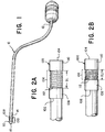
- Figures 1, 2A, and 2B illustrate an obstruction sensing element 100 using force detection, with a center lumen 16.
- Figure 1 illustrates a catheter 10 having a proximal end 12, a distal end 14 and the inner lumen 16. At the proximal end 12 can be a handle to steer the catheter 10, certain electronics in support of the invention and an advancer for the obstruction capturing device 300. At the distal end 14 of the catheter 10 can be disposed a force sensing element 100.
- the force sensing element 100 can include a proximal end 102, a distal end 104, and a gap 106 therebetween.
- An electromagnetic transceiver 108 can be fixed to the proximal end 102 of the force sensing element 100.
- An electromagnetic sensor 110 can be disposed at the distal end 104 of the force sensing element 100 and separated from the transceiver 108 by the gap 106. The electromagnetic sensor 110 is also slidable along the force sensing element 100.
- a spring 112 is disposed between the transceiver 108 and the sensor 110 and provides resistance to a proximal movement of the sensor 110.
- the obstruction sensing element 100 acts as a force sensing element to determine if the tip of the catheter 10 contacts an obstruction C in the vasculature V (see Figures 3A and 3B ).
- the obstruction C is typically a blood clot, but the sensor can be used to sense the impact into any obstruction, including a previously deployed stent or other natural or implanted features.
- the transceiver 108 can transmit a signal 114 and that signal is received by the sensor 110.
- the sensor 110 is displaceable along the catheter 10 and the spring 112 applies a distally directed force. When the sensor 110 contacts the obstruction C, it is pushed proximally, closing the gap 106 between the sensor 110 and the transceiver 108.
- the gap 106 in the uncontacted condition, has an at rest gap length GL and then once in contact, the gap 106 shrinks so the distance between the sensor 110 and the transceiver 108 is now a contact gap length GL1.
- the contact gap length GL1 is always smaller than the at rest gap length GL (i.e. GL>GL1). This change in distance changes the nature of the received signal and provides a position signal.
- the sensor 110 can detect whether the signal being received from the transceiver 108 has a frequency of frequency F1 or frequency F2 or frequency Fn. The transceiver 108 can then know the relative location of the sensor 110 relative to the transceiver 108 since the transceiver 108 is emitting signals, in one example, with a fixed initial frequency and/or wavelength.
- the sensor 110 can be a coil that can receive/transmit the signal. In one example, the sensor 110 can be a passive coil that charges and discharges based on the signal received.
- the emitted signal from the transceiver 108 can have a frequency to detect spring 112 compression.
- the spring compression can be tuned with a spring constant (k) in a way that it can have enough distance changes based on blood clot C variations.
- k spring constant
- the spring compresses, resulting in a smaller distance than when the catheter 10 has not hit a blood clot.
- This compression can result in the signal from the transceiver 108 to the sensor 110 traveling faster and the signal can have a higher strength.
- the sensor 110 can detect whether the distal end 14 of the catheter 10 has encountered an obstruction C. See, Figures 3A & 3B .
- the signal 114 received by the sensor 110 comprises a first frequency F1, and wavelength ⁇ 1, and a first power P1, as illustrated in Figure 3A .
- the transceiver 108 and sensor 110 are at the at rest position with full gap length GL.
- the signal 114 received by the sensor 110 now has a second frequency F2, due to a second wavelength ⁇ 2 and a second power P2, as illustrated in Figure 3B .
- the perceived change in frequency/wavelength identified by the sensor 110 during movement can be a product of the doppler effect. Knowing the emission frequency F1 and the second frequency F2, the distance the sensor 110 has moved can be calculated. In addition, knowing the spring constant (k) of the spring 112, allows one to calculate how much force was needed to move the sensor 110 the detected distance. The force required can then be used to determine the general nature of the obstruction C. The difference in transmitted and received signal power P1, P2 can also be calibrated to determine distance the sensor 110 moved. As the sensor 110 moves closer to the transceiver 108, the power increases. Thus, a position signal can be generated based on the first frequency F1, the second frequency F2, the first power P1, and/or the second power P2.
- the force sensing element 100 can also include a fast anatomical mapping (FAM) sensor, as described below.
- FAM fast anatomical mapping
- FIGS 4 and 5 illustrate an additional example of a fast anatomical mapping (FAM) sensor or an electromagnetic sensing element 200 with a center lumen 206.
- the electromagnetic sensing element 200 has a proximal end 202, distal end 204, and the lumen 206 therethrough.
- the inner lumen 206 has an inner diameter ID configured to pass a neurovascular device.
- the electromagnetic sensing element 200 can have a hollow tube 208 spanning from the proximal end 202, and distal end 204 and shares the inner lumen 206.
- a coil 210 can be wound around the tube 208, disposed outside the inner lumen 206, and can provide a mapping signal.
- a wire 212 can be connected to the coil 210 and transmit the mapping signal to a processor 214.
- Typical FAM sensors do not have an inner lumen 206 to pass neurovascular devices. This adds an extra step to the surgical process since the mapping must be done first and then the neurovascular device can be introduced.
- the neurovascular device can be introduced as the mapping is being performed.
- a clot retrieving device can be introduced and used without compromising the accuracy of the location of the electromagnetic sensing element 200.
- An example of the electromagnetic sensing element 200 can be a coil like inductor that is constructed as follows.
- a very thin layer hollow rigid ferrite tube 208 can be approximately a length L of the electromagnetic sensing element 200 and the inner diameter ID can be the same as the inner diameter of a catheter sheath (not illustrated).
- a wire (coil) 210 can be wound onto the thin layer ferrite tube 208.
- a sensor wire 212 in one example a thin twisted pair wire, can be attached via solder onto the winded coil 210 that acts as the sensor that carries a mapping signal from the sensor coil to a processing unit 214.
- the electromagnetic sensing element's 200 open inner diameter ID/lumen 206 allows for neurovascular instruments to pass through.
- Disposing the electromagnetic sensing element 200 the distal end 204 of the device allows the surgeon to know exactly where the catheter is in the vascular as she tries to locate the obstruction/blood clot C. This is done by plotting a 3D image as the catheter 10 is advanced.
- Figure 5 illustrates the plotting of lung airway branches, which are very similar to blood vessel branches.
- FIGs 6 and 7 illustrate an example of a device 300 to remove a clot/obstruction C in the vascular V of a patient.
- the device 300 includes a delivery tube 302 sized to be passed through the catheter 10 once the obstruction C has been located using at least one of the elements 100, 200 described above.
- Multiple capture anchors 304 are disposed in the delivery tube 302.
- the capture anchors 304 can be made of a shape-memory material allow them to have an advancing position and a capture position. In the advancing position the capture anchors 304 are generally straight and are approximately parallel to a center axis 306 of the delivery tube 302. This position is illustrated in Figure 6 and allows for the device 300 to be easily moved through the catheter 10 to the treatment location.
- the generally straight nature of the capture anchors 304 also assists in in penetrating through the blood clot (see Figure 8B ).
- each of the plurality of anchors 304 When the capture anchors 304 are in the capture position, a distal end 308 of each of the plurality of anchors 304 expand outwards and curves 310 proximally. Said differently, the capture anchors 304 "bloom" as they expand away from the center axis 306 and the tips of the anchors 304 curve backwards toward the delivery tube 302. Alternately, the plurality of capture anchors 304 can expand circumferentially. Thus, the most distal portion of the anchors 304 are the curves 310, and the tips 308 of the anchors 304 are pointing proximally. As the capture anchors 304 curve they expand to approximately the diameter of the blood vessel in which they are deployed.
- the anchors 304 can be made of a resilient material such as spring-temper stainless steel or, more preferably a super elastic material such as Nitinol.
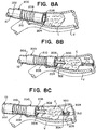
- FIGs 8A-8C illustrate an example of a clot C removal.
- the catheter 10 is advanced through multiple blood vessels, while a 3D image is created (Fast Anatomical Mapping) using the electromagnetic sensing element 200.
- the catheter 10 is advanced until resistance is sensed at the tip of the catheter 10 by the force sensor 100. This is typically an indication that the clot C has been located. See, Figure 8A .
- the blood clot retrieving device 300 is deployed, with the nitinol anchors 304 in their straight advancing position until the clot has been fully breached. See, Figure 8B .
- the anchors 304 are advanced further into their capture position resulting in multiple nitinol preformed shapes expanding toward the wall of the blood vessel V in a circumferential way. Finally, the clot C can be pulled into the catheter lumen 16 and the entire system is removed.
- Figures 9 and 10 illustrate a method of detecting and retrieving a blood clot, having the steps of advancing a catheter 10 with a clot sensing element 100, 200 through a patient vascular V (step 400).
- the patient vascular V can be mapped in real-time using FAM (step 402).
- FAM FAM
- the force sensor 100 Once the tip of the catheter 10 contacts the clot the force sensor 100 generates a position signal indicating the clot sensing element 100, 200 contacted the clot C in the patient vascular V (step 404).
- a blood clot retrieval device 300 can be deployed through the catheter 10 and lumen 16, 206 to remove the clot C from the patient vascular V (step 406).
- the deploying step (step 406) can also include penetrating through the clot C using the plurality of capture anchors 304 in an advancing position (step 408).
- the plurality of capture anchors 304 can be expanded into a capture position (step 410) and the blood clot retrieval device 300 is withdrawn back into the catheter 10 with at least a portion of the blood clot C (step 412).
- the withdrawing step (412) can also include aspirating through the catheter 10 (step 414).
- the generating step (step 404) can have the step of disposing an electromagnetic transceiver 108 at a proximal end 102 of the clot sensing element 100, 200 (step 416) and an electromagnetic sensor 110 at a first distance GL from the transceiver 108 (step 418).
- a spring 112 can be disposed between the transceiver 108 and the sensor 110, the spring 112 providing resistance to a proximal movement of the sensor 110 (step 420).
- the transceiver 108 can emit a signal (step 422) which can be received at the sensor 110 (step 424).
- a processor can determine the proximal movement of the sensor 110 based on at least one of a change in frequency of the signal and a change in power of the signal (step 426). This can generate a position signal based on the proximal movement of the sensor 100 (step 428).
- the emitted signal in an example, can be at a fixed wavelength/frequency.
- the receiving step (step 424) can include receiving at the sensor 110 the signal comprising a first frequency and a first power when the sensor 110 is at the first distance GL (step 430). Then, receiving at the sensor 110 the signal comprising a second frequency and a second power when the sensor 110 is at a second distance GL1 shorter than the first distance GL (step 432).
- the change from the first frequency to the second frequency can be based on the change from the first distance GL to the second distance GL1. Further, the change from the first power to the second power can also be based on the change from the first distance to the second distance.
- the mapping step (step 402) can include disposing a hollow tube 208 having proximal and distal ends 202, 204, and an inner lumen 206 (step 434). Then winding a coil 210 around the tube 208, disposed outside the inner lumen 206, to providing a mapping signal (step 436) and connecting a wire 212 to the coil 210 to transmit the mapping signal to a processor 214 (step 438).
- the inner lumen 206 can have an inner diameter ID configured to pass a neurovascular device, such as embolic coils, flow diverters and stents.
- the hollow tube 208 can have a hollow rigid ferrite tube approximately a length L of the electromagnetic sensing element 200 and the wire 212 can be a twisted pair.
- the examples above contemplate one or more elements being radiopaque and visible under fluoroscopy.
- the elements can be used as markers as the Cather 10 is advanced and retreated out of the patient.
Landscapes
- Health & Medical Sciences (AREA)
- Life Sciences & Earth Sciences (AREA)
- Engineering & Computer Science (AREA)
- Biomedical Technology (AREA)
- General Health & Medical Sciences (AREA)
- Veterinary Medicine (AREA)
- Public Health (AREA)
- Animal Behavior & Ethology (AREA)
- Heart & Thoracic Surgery (AREA)
- Surgery (AREA)
- Molecular Biology (AREA)
- Medical Informatics (AREA)
- Biophysics (AREA)
- Nuclear Medicine, Radiotherapy & Molecular Imaging (AREA)
- Pathology (AREA)
- Vascular Medicine (AREA)
- Physics & Mathematics (AREA)
- Pulmonology (AREA)
- Anesthesiology (AREA)
- Hematology (AREA)
- Radiology & Medical Imaging (AREA)
- Oral & Maxillofacial Surgery (AREA)
- Orthopedic Medicine & Surgery (AREA)
- Transplantation (AREA)
- Cardiology (AREA)
- Human Computer Interaction (AREA)
- Neurology (AREA)
- Robotics (AREA)
- Psychiatry (AREA)
- Psychology (AREA)
- Social Psychology (AREA)
- Hospice & Palliative Care (AREA)
- Developmental Disabilities (AREA)
- Child & Adolescent Psychology (AREA)
- Media Introduction/Drainage Providing Device (AREA)
- Measurement Of The Respiration, Hearing Ability, Form, And Blood Characteristics Of Living Organisms (AREA)
- Surgical Instruments (AREA)
- Investigating Or Analysing Biological Materials (AREA)
Abstract
Description
- The invention relates to a force sensing and fast anatomical mapping sensor package and a novel clot capture device.
- Ischemic stroke is the most prevalent (∼75%) of the two types of strokes. The other type of stroke being hemorrhagic stroke, which deals with treatment of aneurisms. Ischemic stroke occurs when the blood vessels that supply the blood to the brain are clotted from plaque buildup within a vessel lumen. This results in blood supply interruption to the brain, resulting in ischemic stroke because of the blood clot.
- Current devices are advanced to the blood clotting area through the aid of a guidewire. The guidewire is placed within the clot region by feel feedback. One the surgeon believes she is in the clot region, she advances the catheter and the clot retrieving device. The force feedback is not accurate all the time due to the clot being located far away from the point of guidewire introduction. In addition, the advancement of the guidewire can be progressed in a false passage and the surgeon has to retry a different passage again, until resistance is felt from the guidewire.
- Additionally, the current imaging techniques use fluoroscopic radiation to track the movement of the guidewire/catheter. Fluoroscopy involves passing a continuous X-ray beam through the body part to be imaged and sent to a video monitor so that the body part and the motion of the guidewire/catheter can be seen in detail. The use of fluoroscopy is associated with radiation-related risks, including radiation-induced injuries to the skin and underlying tissues ("burns"), which occur shortly after the exposure, and radiation-induced cancers.
- Thus, what is needed is a device that can reach a clot region with high accuracy and avoid the harmful use of radiation.
- Examples of the present invention can include a force sensing element with center lumen. The example can have a catheter with an inner lumen, a distal end, and the sensing element disposed at the distal end. An electromagnetic transceiver can emit or receive a signal and is fixed to a proximal end of the sensing element. An electromagnetic sensor can receive the signal and is disposed at the distal end of the sensing element. The sensor can be slidable along the sensing element and generate a position signal. A spring can be disposed between the transceiver and the sensor providing resistance to a proximal movement of the sensor. When the sensor is in a first position, the signal received by the sensor can have a first frequency and a first power and when the sensor is in a second position, the signal received by the sensor can have a second frequency and a second power. Also, the position signal is generated based on at least one of the first frequency, the second frequency, the first power, and the second power. The force sensing element can also have a fast anatomical mapping sensor.
- The force sensing element above also can have the first position being a fully distal position on the sensing element, and the second position being a proximal position near the transceiver. A spring constant can control an amount of force needed to move the sensor.
- An electromagnetic sensing element with a center lumen may include a hollow tube with a proximal end, and distal end, and an inner lumen A coil can be wound around the tube, disposed outside the inner lumen, and provide a mapping signal. A wire can be connected to the coil and transmitting the mapping signal to a processor, and the center lumen has an inner diameter configured to pass a neurovascular device. The tube can be a hollow rigid ferrite tube approximately a length of the electromagnetic sensing element; and the wire a twisted pair.
- An example of a device to remove an obstruction in a vascular may include a delivery tube and a capture anchors disposed in the delivery tube with an advancing position and a capture position. When the capture anchors are in the advancing position they are approximately parallel to a center axis of the delivery tube, and in the capture position, a distal end of each of the plurality of anchors expand outwards and curves proximally. In examples. the obstruction is captured within the curve of each of the plurality of anchors. Further, the capture anchors can expand circumferentially.
- A method of detecting and retrieving a blood clot can include the steps of advancing a catheter with a clot sensing element through a patient vascular. The catheter can map, using an electromagnetic sensor disposed at a distal end of the clot sensing element, the patient vascular. The force sensor can generate a position signal indicating the clot sensing element contacted the clot in the patient vascular. Once located, a blood clot retrieval device can be deployed through the catheter and a lumen in the clot sensing element to remove the clot from the patient vascular.
- The deploying step further can include penetrating through the clot using a plurality of capture anchors in an advancing position, expanding the plurality of capture anchors into a capture position; and withdrawing the blood clot retrieval device back into the catheter with a portion of the blood clot. Withdrawing can further include aspirating through the catheter.
- The generating step can include disposing an electromagnetic transceiver at a proximal end of the clot sensing element and disposing an electromagnetic sensor at the distal end of the clot sensing element a first distance from the transceiver. A spring can be disposed between the transceiver and the sensor, the spring providing resistance to a proximal movement of the sensor. A signal can be emitted from the transceiver and received at the sensor. The proximal movement of the sensor can be determined based on at least one of a change in frequency of the signal and a change in power of the signal. The position signal can be generated based on the proximal movement of the sensor.
- The receiving step can include receiving at the sensor the signal comprising a first frequency and a first power when the sensor is at the first distance and receiving at the sensor the signal comprising a second frequency and a second power when the sensor is at a second distance shorter than the first distance. The change from the first frequency to the second frequency can be based on the change from the first distance to the second distance, and the change from the first power to the second power is based on the change from the first distance to the second distance.
- The mapping step can dispose a hollow tube with a proximal end, and distal end, and an inner lumen. A coil can be wound around the tube, disposed outside the inner lumen, and provides a mapping signal. A wire can be connected to the coil and transmitting the mapping signal to a processor and the inner lumen has an inner diameter configured to pass a neurovascular device. The hollow tube can have a hollow rigid ferrite tube approximately a length of the electromagnetic sensing element and the wire can be a twisted pair.
- The above and further aspects of this invention are further discussed with reference to the following description in conjunction with the accompanying drawings, in which like numerals indicate like structural elements and features in various figures. The drawings are not necessarily to scale, emphasis instead being placed upon illustrating principles of the invention. The figures depict one or more implementations of the inventive devices, by way of example only, not by way of limitation.
-
Figure 1 is a front side perspective view of the sensing element disposed on a catheter and advancer; -
Figure 2A is a side view of the force sensing element in the uncontracted position; -
Figure 2B is a side view of the force sensing element in the contracted position, typically in contact with an obstruction; -
Figure 3A is a view of the transmitter and sensor with signals at the at rest position; -
Figure 3B is a view of the transmitter and sensor with signals at the at contact position; -
Figure 4 is a front-side perspective view of the sensing element; -
Figure 5 is an example of a 3D image created by Fast Anatomical Mapping (FAM) branches of the lung; -
Figure 6 is a front-side perspective view of an obstruction capture device of the present invention in the advancing position; -
Figure 7 is a front-side perspective view of an obstruction capture device of the present invention in the capture position; -
Figure 8A illustrates an obstruction sensing and capture device in the vasculature encountering an obstruction; -
Figure 8B illustrates the deployment of the obstruction capture device; -
Figure 8C illustrates the obstruction capture device deployed; -
Figure 9 is a flow chart of an example of a method of the present invention; and -
Figure 10 is another flow chart of an example of a method of the present invention. -
Figures 1, 2A, and 2B illustrate anobstruction sensing element 100 using force detection, with acenter lumen 16.Figure 1 illustrates acatheter 10 having aproximal end 12, adistal end 14 and theinner lumen 16. At theproximal end 12 can be a handle to steer thecatheter 10, certain electronics in support of the invention and an advancer for theobstruction capturing device 300. At thedistal end 14 of thecatheter 10 can be disposed aforce sensing element 100. - The
force sensing element 100 can include aproximal end 102, adistal end 104, and agap 106 therebetween. Anelectromagnetic transceiver 108 can be fixed to theproximal end 102 of theforce sensing element 100. Anelectromagnetic sensor 110 can be disposed at thedistal end 104 of theforce sensing element 100 and separated from thetransceiver 108 by thegap 106. Theelectromagnetic sensor 110 is also slidable along theforce sensing element 100. Aspring 112 is disposed between thetransceiver 108 and thesensor 110 and provides resistance to a proximal movement of thesensor 110. - The
obstruction sensing element 100 acts as a force sensing element to determine if the tip of thecatheter 10 contacts an obstruction C in the vasculature V (seeFigures 3A and 3B ). The obstruction C is typically a blood clot, but the sensor can be used to sense the impact into any obstruction, including a previously deployed stent or other natural or implanted features. To determine contact with the obstruction C, thetransceiver 108 can transmit asignal 114 and that signal is received by thesensor 110. Thesensor 110 is displaceable along thecatheter 10 and thespring 112 applies a distally directed force. When thesensor 110 contacts the obstruction C, it is pushed proximally, closing thegap 106 between thesensor 110 and thetransceiver 108. Said differently, in the uncontacted condition, thegap 106 has an at rest gap length GL and then once in contact, thegap 106 shrinks so the distance between thesensor 110 and thetransceiver 108 is now a contact gap length GL1. The contact gap length GL1 is always smaller than the at rest gap length GL (i.e. GL>GL1). This change in distance changes the nature of the received signal and provides a position signal. - The
sensor 110 can detect whether the signal being received from thetransceiver 108 has a frequency of frequency F1 or frequency F2 or frequency Fn. Thetransceiver 108 can then know the relative location of thesensor 110 relative to thetransceiver 108 since thetransceiver 108 is emitting signals, in one example, with a fixed initial frequency and/or wavelength. Thesensor 110 can be a coil that can receive/transmit the signal. In one example, thesensor 110 can be a passive coil that charges and discharges based on the signal received. - The emitted signal from the transceiver 108can have a frequency to detect
spring 112 compression. The spring compression can be tuned with a spring constant (k) in a way that it can have enough distance changes based on blood clot C variations. When a blood clot C is hits thespring 112, the spring compresses, resulting in a smaller distance than when thecatheter 10 has not hit a blood clot. This compression can result in the signal from thetransceiver 108 to thesensor 110 traveling faster and the signal can have a higher strength. Thus, thesensor 110 can detect whether thedistal end 14 of thecatheter 10 has encountered an obstruction C. See,Figures 3A & 3B . - Alternately, when the
sensor 110 is in a first position, i.e. uncontacted, thesignal 114 received by thesensor 110 comprises a first frequency F1, and wavelength λ1, and a first power P1, as illustrated inFigure 3A . Thetransceiver 108 andsensor 110 are at the at rest position with full gap length GL. As thesensor 110 contacts the obstruction C, it moves to a second position (obstruction contact), thesignal 114 received by thesensor 110 now has a second frequency F2, due to a second wavelength λ2 and a second power P2, as illustrated inFigure 3B . - One of ordinary skill is aware that frequency and wavelength are related through the speed of light (c), F=c/λ. The perceived change in frequency/wavelength identified by the
sensor 110 during movement can be a product of the doppler effect. Knowing the emission frequency F1 and the second frequency F2, the distance thesensor 110 has moved can be calculated. In addition, knowing the spring constant (k) of thespring 112, allows one to calculate how much force was needed to move thesensor 110 the detected distance. The force required can then be used to determine the general nature of the obstruction C. The difference in transmitted and received signal power P1, P2 can also be calibrated to determine distance thesensor 110 moved. As thesensor 110 moves closer to thetransceiver 108, the power increases. Thus, a position signal can be generated based on the first frequency F1, the second frequency F2, the first power P1, and/or the second power P2. Theforce sensing element 100 can also include a fast anatomical mapping (FAM) sensor, as described below. -
Figures 4 and 5 illustrate an additional example of a fast anatomical mapping (FAM) sensor or anelectromagnetic sensing element 200 with acenter lumen 206. Theelectromagnetic sensing element 200 has aproximal end 202,distal end 204, and thelumen 206 therethrough. Theinner lumen 206 has an inner diameter ID configured to pass a neurovascular device. Theelectromagnetic sensing element 200 can have ahollow tube 208 spanning from theproximal end 202, anddistal end 204 and shares theinner lumen 206. Acoil 210 can be wound around thetube 208, disposed outside theinner lumen 206, and can provide a mapping signal. Awire 212 can be connected to thecoil 210 and transmit the mapping signal to aprocessor 214. Typical FAM sensors do not have aninner lumen 206 to pass neurovascular devices. This adds an extra step to the surgical process since the mapping must be done first and then the neurovascular device can be introduced. In the present invention, the neurovascular device can be introduced as the mapping is being performed. Thus, a clot retrieving device can be introduced and used without compromising the accuracy of the location of theelectromagnetic sensing element 200. - An example of the
electromagnetic sensing element 200 can be a coil like inductor that is constructed as follows. A very thin layer hollowrigid ferrite tube 208 can be approximately a length L of theelectromagnetic sensing element 200 and the inner diameter ID can be the same as the inner diameter of a catheter sheath (not illustrated). A wire (coil) 210 can be wound onto the thinlayer ferrite tube 208. Asensor wire 212, in one example a thin twisted pair wire, can be attached via solder onto thewinded coil 210 that acts as the sensor that carries a mapping signal from the sensor coil to aprocessing unit 214. The electromagnetic sensing element's 200 open inner diameter ID/lumen 206 allows for neurovascular instruments to pass through. - Disposing the
electromagnetic sensing element 200 thedistal end 204 of the device allows the surgeon to know exactly where the catheter is in the vascular as she tries to locate the obstruction/blood clot C. This is done by plotting a 3D image as thecatheter 10 is advanced.Figure 5 illustrates the plotting of lung airway branches, which are very similar to blood vessel branches. One of the advantages is that if the catheter is advanced in a direction where the 3D image is constructed, and no blood clot is found the surgeon does not have to pursue the same passage again. -
Figures 6 and 7 illustrate an example of adevice 300 to remove a clot/obstruction C in the vascular V of a patient. Thedevice 300 includes adelivery tube 302 sized to be passed through thecatheter 10 once the obstruction C has been located using at least one of theelements delivery tube 302. The capture anchors 304 can be made of a shape-memory material allow them to have an advancing position and a capture position. In the advancing position the capture anchors 304 are generally straight and are approximately parallel to acenter axis 306 of thedelivery tube 302. This position is illustrated inFigure 6 and allows for thedevice 300 to be easily moved through thecatheter 10 to the treatment location. The generally straight nature of the capture anchors 304 also assists in in penetrating through the blood clot (seeFigure 8B ). - When the capture anchors 304 are in the capture position, a
distal end 308 of each of the plurality ofanchors 304 expand outwards and curves 310 proximally. Said differently, the capture anchors 304 "bloom" as they expand away from thecenter axis 306 and the tips of theanchors 304 curve backwards toward thedelivery tube 302. Alternately, the plurality of capture anchors 304 can expand circumferentially. Thus, the most distal portion of theanchors 304 are thecurves 310, and thetips 308 of theanchors 304 are pointing proximally. As the capture anchors 304 curve they expand to approximately the diameter of the blood vessel in which they are deployed. In that way, they can anchor into a majority of the clot C to remove it from the vessel. As thedelivery tube 302 is drawn back into thecatheter 10, the obstruction C is captured by theanchors 304 and within thecurve 310 of each of the plurality ofanchors 304. Alternately, the obstruction C does not need to be displaced into thecatheter 10 but removed by proximally displacing both thecatheter 10 and thedelivery tube 302. Aspiration can occur through thecatheter 10 as the blood clot is moved to reduce or eliminate any stray piece of the clot from breaking free and passing through the blood stream. In one embodiment, theanchors 304 can be made of a resilient material such as spring-temper stainless steel or, more preferably a super elastic material such as Nitinol. -
Figures 8A-8C illustrate an example of a clot C removal. Thecatheter 10 is advanced through multiple blood vessels, while a 3D image is created (Fast Anatomical Mapping) using theelectromagnetic sensing element 200. Thecatheter 10 is advanced until resistance is sensed at the tip of thecatheter 10 by theforce sensor 100. This is typically an indication that the clot C has been located. See,Figure 8A . Next, the bloodclot retrieving device 300 is deployed, with the nitinol anchors 304 in their straight advancing position until the clot has been fully breached. See,Figure 8B . Theanchors 304 are advanced further into their capture position resulting in multiple nitinol preformed shapes expanding toward the wall of the blood vessel V in a circumferential way. Finally, the clot C can be pulled into thecatheter lumen 16 and the entire system is removed. -
Figures 9 and10 illustrate a method of detecting and retrieving a blood clot, having the steps of advancing acatheter 10 with aclot sensing element electromagnetic sensor 200 disposed at a distal end of the clot sensing element, the patient vascular V can be mapped in real-time using FAM (step 402). Once the tip of thecatheter 10 contacts the clot theforce sensor 100 generates a position signal indicating theclot sensing element clot retrieval device 300 can be deployed through thecatheter 10 andlumen - The deploying step (step 406) can also include penetrating through the clot C using the plurality of capture anchors 304 in an advancing position (step 408). The plurality of capture anchors 304 can be expanded into a capture position (step 410) and the blood
clot retrieval device 300 is withdrawn back into thecatheter 10 with at least a portion of the blood clot C (step 412). The withdrawing step (412) can also include aspirating through the catheter 10 (step 414). - The generating step (step 404) can have the step of disposing an
electromagnetic transceiver 108 at aproximal end 102 of theclot sensing element 100, 200 (step 416) and anelectromagnetic sensor 110 at a first distance GL from the transceiver 108 (step 418). Aspring 112 can be disposed between thetransceiver 108 and thesensor 110, thespring 112 providing resistance to a proximal movement of the sensor 110 (step 420). Thetransceiver 108 can emit a signal (step 422) which can be received at the sensor 110 (step 424). In an example, a processor can determine the proximal movement of thesensor 110 based on at least one of a change in frequency of the signal and a change in power of the signal (step 426). This can generate a position signal based on the proximal movement of the sensor 100 (step 428). The emitted signal, in an example, can be at a fixed wavelength/frequency. - The receiving step (step 424) can include receiving at the
sensor 110 the signal comprising a first frequency and a first power when thesensor 110 is at the first distance GL (step 430). Then, receiving at thesensor 110 the signal comprising a second frequency and a second power when thesensor 110 is at a second distance GL1 shorter than the first distance GL (step 432). The change from the first frequency to the second frequency can be based on the change from the first distance GL to the second distance GL1. Further, the change from the first power to the second power can also be based on the change from the first distance to the second distance. - The mapping step (step 402) can include disposing a
hollow tube 208 having proximal anddistal ends coil 210 around thetube 208, disposed outside theinner lumen 206, to providing a mapping signal (step 436) and connecting awire 212 to thecoil 210 to transmit the mapping signal to a processor 214 (step 438). Theinner lumen 206 can have an inner diameter ID configured to pass a neurovascular device, such as embolic coils, flow diverters and stents. - As noted above, the
hollow tube 208 can have a hollow rigid ferrite tube approximately a length L of theelectromagnetic sensing element 200 and thewire 212 can be a twisted pair. - Note that the examples above contemplate one or more elements being radiopaque and visible under fluoroscopy. The elements can be used as markers as the
Cather 10 is advanced and retreated out of the patient. - While the foregoing has described what are considered to be the best mode and/or other examples, it is understood that various modifications may be made therein and that the subject matter disclosed herein may be implemented in various forms and examples, and that the teachings may be applied in numerous applications, only some of which have been described herein. It is intended by the following claims to claim any and all applications, modifications and variations that fall within the true scope of the present teachings.
-
- 1. A method of detecting and retrieving a blood clot, comprising the steps of:
- advancing a catheter with a clot sensing element through a patient vascular;
- mapping, using an electromagnetic sensor disposed at a distal end of the clot sensing element, the patient vascular;
- generating, from a force sensor, a position signal indicating the clot sensing element contacted the clot in the patient vascular; and
- deploying a blood clot retrieval device through the catheter and a lumen in the clot sensing element to remove the clot from the patient vascular.
- 2. The method of aspect 1, wherein the deploying step further comprises the steps of:
- penetrating through the clot using a plurality of capture anchors in an advancing position;
- expanding the plurality of capture anchors into a capture position; and
- withdrawing the blood clot retrieval device back into the catheter with a portion of the blood clot.
- 3. The method of aspect 2, wherein the withdrawing step further comprises the step of aspirating through the catheter.
- 4. The method of aspect 1, wherein the generating step comprises the steps of:
- disposing an electromagnetic transceiver at a proximal end of the clot sensing element;
- disposing an electromagnetic sensor at the distal end of the clot sensing element a first distance from the transceiver;
- disposing a spring between the transceiver and the sensor, the spring providing resistance to a proximal movement of the sensor;
- emitting, from the transceiver, a signal;
- receiving the signal at the sensor;
- determining the proximal movement of the sensor based on at least one of a change in frequency of the signal and a change in power of the signal; and
- generating the position signal based on the proximal movement of the sensor.
- 5. The method of aspect 4, wherein the receiving step comprises the steps of:
- receiving at the sensor the signal comprising a first frequency and a first power when the sensor is at the first distance; and
- receiving at the sensor the signal comprising a second frequency and a second power when the sensor is at a second distance shorter than the first distance;
- wherein the change from the first frequency to the second frequency is based on the change from the first distance to the second distance, and
- wherein the change from the first power to the second power is based on the change from the first distance to the second distance.
- 6. The method of aspect 1, wherein the mapping step comprises the steps of:
- disposing a hollow tube comprising a proximal end, and distal end, and an inner lumen;
- winding a coil around the tube, disposed outside the inner lumen, and providing a mapping signal; and
- connecting a wire to the coil and transmitting the mapping signal to a processor,
- wherein the inner lumen has an inner diameter configured to pass a neurovascular device.
- 7. The method of aspect 6, wherein:
- the hollow tube comprises a hollow rigid ferrite tube approximately a length of the electromagnetic sensing element; and
- the wire is a twisted pair.
Claims (9)
- A force sensing element with center lumen, comprising:a catheter comprising an inner lumen, a distal end, and the sensing element disposed at the distal end;an electromagnetic transceiver at least one of emitting or receiving a signal, and is fixed to a proximal end of the sensing element;an electromagnetic sensor receiving the signal, is disposed at the distal end of the sensing element, slidable along the sensing element, and generates a position signal; anda spring disposed between the transceiver and the sensor providing resistance to a proximal movement of the sensor,wherein when the sensor is in a first position, the signal received by the sensor comprises a first frequency and a first power;wherein when the sensor is in a second position, the signal received by the sensor comprises a second frequency and a second power; andwherein the position signal is generated based on at least one of the first frequency, the second frequency, the first power, and the second power.
- The force sensing element of claim 1, wherein the electromagnetic sensor further comprises a fast anatomical mapping (FAM) sensor.
- The force sensing element of claim 1,
wherein the first position is a fully distal position on the sensing element, and
wherein the second position is a proximal position near the transceiver. - The force sensing element of claim 1, wherein the spring further comprises a spring constant controlling an amount of force needed to move the sensor.
- An electromagnetic sensing element with a center lumen, comprising:a hollow tube comprising a proximal end, and distal end, and an inner lumen;a coil wound around the tube, disposed outside the inner lumen, and providing a mapping signal; anda wire connected to the coil and transmitting the mapping signal to a processor,wherein the center lumen has an inner diameter configured to pass a neurovascular device.
- The electromagnetic sensing element of claim 5, wherein:the tube comprises a hollow rigid ferrite tube approximately a length of the electromagnetic sensing element; andthe wire is a twisted pair.
- A device to remove an obstruction in a vascular, comprising:a delivery tube; anda plurality of capture anchors disposed in the delivery tube comprising an advancing position and a capture position;wherein when the plurality of capture anchors are in the advancing position they are approximately parallel to a center axis of the delivery tube, andwherein when the plurality of capture anchors are in the capture position, a distal end of each of the plurality of anchors expand outwards and curve proximally.
- The device of claim 7, wherein the obstruction is captured within the curve of each of the plurality of anchors.
- The device of claim 7, wherein the plurality of capture anchors expand circumferentially.
Applications Claiming Priority (1)
| Application Number | Priority Date | Filing Date | Title |
|---|---|---|---|
| US16/001,427 US11839460B2 (en) | 2018-06-06 | 2018-06-06 | Device and method to detect and remove blood clots for treatment of ischemic stroke using force and electromagnetic sensing |
Publications (4)
| Publication Number | Publication Date |
|---|---|
| EP3578223A2 true EP3578223A2 (en) | 2019-12-11 |
| EP3578223A3 EP3578223A3 (en) | 2020-03-04 |
| EP3578223C0 EP3578223C0 (en) | 2024-01-10 |
| EP3578223B1 EP3578223B1 (en) | 2024-01-10 |
Family
ID=66998065
Family Applications (1)
| Application Number | Title | Priority Date | Filing Date |
|---|---|---|---|
| EP19178388.5A Active EP3578223B1 (en) | 2018-06-06 | 2019-06-05 | A device to detect and remove blood clots for treatment of ischemic stroke using force and electromagnetic sensing |
Country Status (7)
| Country | Link |
|---|---|
| US (2) | US11839460B2 (en) |
| EP (1) | EP3578223B1 (en) |
| JP (1) | JP7408301B2 (en) |
| KR (1) | KR102704493B1 (en) |
| CN (1) | CN110559538B (en) |
| BR (1) | BR102019011419A2 (en) |
| ES (1) | ES2971075T3 (en) |
Families Citing this family (6)
| Publication number | Priority date | Publication date | Assignee | Title |
|---|---|---|---|---|
| ES3009676T3 (en) | 2018-08-24 | 2025-03-31 | Neuravi Ltd | Apparatus for managing acute ischemic events |
| US11679195B2 (en) | 2021-04-27 | 2023-06-20 | Contego Medical, Inc. | Thrombus aspiration system and methods for controlling blood loss |
| EP4108188A1 (en) * | 2021-06-23 | 2022-12-28 | Artedrone | Medical device, system and method for retrieving a thrombus from a vessel, and method for producing a device |
| WO2024091571A1 (en) * | 2022-10-26 | 2024-05-02 | Microvention, Inc. | Systems and methods to provide haptic feedback on clot engagement |
| US12370078B2 (en) | 2023-10-27 | 2025-07-29 | NEXT Life Sciences, Inc. | Apparatus and method for delivery and/or removal of occlusions in the body |
| CN118625722B (en) * | 2024-08-09 | 2024-10-29 | 浙江巴泰医疗科技有限公司 | A pipe pressing device control system for a suction device |
Family Cites Families (17)
| Publication number | Priority date | Publication date | Assignee | Title |
|---|---|---|---|---|
| US6511492B1 (en) | 1998-05-01 | 2003-01-28 | Microvention, Inc. | Embolectomy catheters and methods for treating stroke and other small vessel thromboembolic disorders |
| US6638245B2 (en) * | 2001-06-26 | 2003-10-28 | Concentric Medical, Inc. | Balloon catheter |
| US20080009772A1 (en) | 2003-11-26 | 2008-01-10 | Wicab, Inc. | Systems and methods for altering brain and body functions and for treating conditions and diseases of the same |
| US8617152B2 (en) * | 2004-11-15 | 2013-12-31 | Medtronic Ablation Frontiers Llc | Ablation system with feedback |
| ES2425388T3 (en) * | 2005-05-06 | 2013-10-15 | Vasonova, Inc. | Apparatus for guiding and positioning an endovascular device |
| US8585732B2 (en) * | 2006-06-14 | 2013-11-19 | DePuy Synthes Products, LLC | Retrieval device with sidewall grippers |
| US8636715B2 (en) * | 2006-09-25 | 2014-01-28 | Medtronic Vascular, Inc. | High torque, low profile catheters and methods for transluminal interventions |
| US8357152B2 (en) | 2007-10-08 | 2013-01-22 | Biosense Webster (Israel), Ltd. | Catheter with pressure sensing |
| US8535308B2 (en) | 2007-10-08 | 2013-09-17 | Biosense Webster (Israel), Ltd. | High-sensitivity pressure-sensing probe |
| US8979772B2 (en) | 2010-11-03 | 2015-03-17 | Biosense Webster (Israel), Ltd. | Zero-drift detection and correction in contact force measurements |
| WO2013166049A1 (en) * | 2012-04-30 | 2013-11-07 | BiO2 Medical, Inc. | Multi-lumen central access vena cava filter apparatus for clot management and method of using same |
| US9226710B2 (en) | 2012-06-25 | 2016-01-05 | Biosense Webster (Israel) Ltd. | Wireless catheter with base wireless transceiver |
| WO2014036034A1 (en) * | 2012-08-27 | 2014-03-06 | University Of Houston | Robotic device and system software, hardware and methods of use for image-guided and robot-assisted surgery |
| US9204841B2 (en) * | 2012-12-31 | 2015-12-08 | Biosense Webster (Israel) Ltd. | Catheter with serially connected sensing structures and methods of calibration and detection |
| EP3043735A1 (en) * | 2013-11-07 | 2016-07-20 | St. Jude Medical, Cardiology Division, Inc. | Medical device with contact force sensing tip |
| US11367947B2 (en) * | 2015-03-16 | 2022-06-21 | St. Jude Medical International Holding S.á r.l. | Field concentrating antennas for magnetic position sensors |
| US10779891B2 (en) * | 2015-10-30 | 2020-09-22 | Acclarent, Inc. | System and method for navigation of surgical instruments |
-
2018
- 2018-06-06 US US16/001,427 patent/US11839460B2/en active Active
-
2019
- 2019-06-03 BR BR102019011419A patent/BR102019011419A2/en not_active Application Discontinuation
- 2019-06-05 KR KR1020190066398A patent/KR102704493B1/en active Active
- 2019-06-05 JP JP2019105110A patent/JP7408301B2/en active Active
- 2019-06-05 EP EP19178388.5A patent/EP3578223B1/en active Active
- 2019-06-05 ES ES19178388T patent/ES2971075T3/en active Active
- 2019-06-06 CN CN201910491653.7A patent/CN110559538B/en active Active
-
2023
- 2023-01-13 US US18/096,622 patent/US12350033B2/en active Active
Also Published As
| Publication number | Publication date |
|---|---|
| US11839460B2 (en) | 2023-12-12 |
| EP3578223A3 (en) | 2020-03-04 |
| ES2971075T3 (en) | 2024-06-03 |
| KR20190139147A (en) | 2019-12-17 |
| CN110559538A (en) | 2019-12-13 |
| CN110559538B (en) | 2024-01-26 |
| US20190374128A1 (en) | 2019-12-12 |
| EP3578223C0 (en) | 2024-01-10 |
| US20230165483A1 (en) | 2023-06-01 |
| US12350033B2 (en) | 2025-07-08 |
| BR102019011419A2 (en) | 2019-12-24 |
| EP3578223B1 (en) | 2024-01-10 |
| JP2019209148A (en) | 2019-12-12 |
| KR102704493B1 (en) | 2024-09-11 |
| JP7408301B2 (en) | 2024-01-05 |
Similar Documents
| Publication | Publication Date | Title |
|---|---|---|
| US12350033B2 (en) | Device and method to detect and remove blood clots for treatment of ischemic stroke using force and electromagnetic sensing | |
| AU2016200819B2 (en) | Angioplasty guidewire | |
| KR102416089B1 (en) | Intravascular treatment site approach | |
| US7248914B2 (en) | Method of navigating medical devices in the presence of radiopaque material | |
| US7955344B2 (en) | Thrombus removal system and process | |
| JP6361941B2 (en) | Improved device and method of use for traversing vascular occlusion | |
| EP3756608A1 (en) | Calculus removing device and method | |
| JP2023553077A (en) | Recovery system and method | |
| CA3162950A1 (en) | Marking element for marking tissue | |
| US20240307128A1 (en) | Devices and methods for guide wire placement | |
| JP6129421B2 (en) | Medical observation system | |
| US11937826B2 (en) | Proximal link wire for preventing premature implant detachment | |
| EP3019104B1 (en) | Reverse loop ablation device | |
| US12137915B2 (en) | Elongating wires for inhibiting premature implant detachment | |
| US20230293184A1 (en) | Interference feature for inhibiting premature embolic implant detachment |
Legal Events
| Date | Code | Title | Description |
|---|---|---|---|
| PUAI | Public reference made under article 153(3) epc to a published international application that has entered the european phase |
Free format text: ORIGINAL CODE: 0009012 |
|
| STAA | Information on the status of an ep patent application or granted ep patent |
Free format text: STATUS: THE APPLICATION HAS BEEN PUBLISHED |
|
| AK | Designated contracting states |
Kind code of ref document: A2 Designated state(s): AL AT BE BG CH CY CZ DE DK EE ES FI FR GB GR HR HU IE IS IT LI LT LU LV MC MK MT NL NO PL PT RO RS SE SI SK SM TR |
|
| AX | Request for extension of the european patent |
Extension state: BA ME |
|
| PUAL | Search report despatched |
Free format text: ORIGINAL CODE: 0009013 |
|
| RIC1 | Information provided on ipc code assigned before grant |
Ipc: A61B 90/00 20160101ALI20200123BHEP Ipc: A61B 17/00 20060101ALI20200123BHEP Ipc: A61M 25/00 20060101AFI20200123BHEP |
|
| AK | Designated contracting states |
Kind code of ref document: A3 Designated state(s): AL AT BE BG CH CY CZ DE DK EE ES FI FR GB GR HR HU IE IS IT LI LT LU LV MC MK MT NL NO PL PT RO RS SE SI SK SM TR |
|
| AX | Request for extension of the european patent |
Extension state: BA ME |
|
| RIC1 | Information provided on ipc code assigned before grant |
Ipc: A61B 17/00 20060101ALI20200128BHEP Ipc: A61B 90/00 20160101ALI20200128BHEP Ipc: A61M 25/00 20060101AFI20200128BHEP |
|
| STAA | Information on the status of an ep patent application or granted ep patent |
Free format text: STATUS: REQUEST FOR EXAMINATION WAS MADE |
|
| 17P | Request for examination filed |
Effective date: 20200904 |
|
| RBV | Designated contracting states (corrected) |
Designated state(s): AL AT BE BG CH CY CZ DE DK EE ES FI FR GB GR HR HU IE IS IT LI LT LU LV MC MK MT NL NO PL PT RO RS SE SI SK SM TR |
|
| STAA | Information on the status of an ep patent application or granted ep patent |
Free format text: STATUS: EXAMINATION IS IN PROGRESS |
|
| 17Q | First examination report despatched |
Effective date: 20220613 |
|
| GRAP | Despatch of communication of intention to grant a patent |
Free format text: ORIGINAL CODE: EPIDOSNIGR1 |
|
| STAA | Information on the status of an ep patent application or granted ep patent |
Free format text: STATUS: GRANT OF PATENT IS INTENDED |
|
| INTG | Intention to grant announced |
Effective date: 20230720 |
|
| GRAJ | Information related to disapproval of communication of intention to grant by the applicant or resumption of examination proceedings by the epo deleted |
Free format text: ORIGINAL CODE: EPIDOSDIGR1 |
|
| STAA | Information on the status of an ep patent application or granted ep patent |
Free format text: STATUS: EXAMINATION IS IN PROGRESS |
|
| GRAP | Despatch of communication of intention to grant a patent |
Free format text: ORIGINAL CODE: EPIDOSNIGR1 |
|
| STAA | Information on the status of an ep patent application or granted ep patent |
Free format text: STATUS: GRANT OF PATENT IS INTENDED |
|
| INTC | Intention to grant announced (deleted) | ||
| INTG | Intention to grant announced |
Effective date: 20231030 |
|
| GRAS | Grant fee paid |
Free format text: ORIGINAL CODE: EPIDOSNIGR3 |
|
| GRAA | (expected) grant |
Free format text: ORIGINAL CODE: 0009210 |
|
| STAA | Information on the status of an ep patent application or granted ep patent |
Free format text: STATUS: THE PATENT HAS BEEN GRANTED |
|
| AK | Designated contracting states |
Kind code of ref document: B1 Designated state(s): AL AT BE BG CH CY CZ DE DK EE ES FI FR GB GR HR HU IE IS IT LI LT LU LV MC MK MT NL NO PL PT RO RS SE SI SK SM TR |
|
| REG | Reference to a national code |
Ref country code: GB Ref legal event code: FG4D |
|
| REG | Reference to a national code |
Ref country code: CH Ref legal event code: EP |
|
| REG | Reference to a national code |
Ref country code: DE Ref legal event code: R096 Ref document number: 602019044759 Country of ref document: DE |
|
| REG | Reference to a national code |
Ref country code: IE Ref legal event code: FG4D |
|
| U01 | Request for unitary effect filed |
Effective date: 20240130 |
|
| U07 | Unitary effect registered |
Designated state(s): AT BE BG DE DK EE FI FR IT LT LU LV MT NL PT SE SI Effective date: 20240208 |
|
| REG | Reference to a national code |
Ref country code: ES Ref legal event code: FG2A Ref document number: 2971075 Country of ref document: ES Kind code of ref document: T3 Effective date: 20240603 |
|
| U20 | Renewal fee for the european patent with unitary effect paid |
Year of fee payment: 6 Effective date: 20240509 |
|
| PG25 | Lapsed in a contracting state [announced via postgrant information from national office to epo] |
Ref country code: IS Free format text: LAPSE BECAUSE OF FAILURE TO SUBMIT A TRANSLATION OF THE DESCRIPTION OR TO PAY THE FEE WITHIN THE PRESCRIBED TIME-LIMIT Effective date: 20240510 |
|
| PG25 | Lapsed in a contracting state [announced via postgrant information from national office to epo] |
Ref country code: GR Free format text: LAPSE BECAUSE OF FAILURE TO SUBMIT A TRANSLATION OF THE DESCRIPTION OR TO PAY THE FEE WITHIN THE PRESCRIBED TIME-LIMIT Effective date: 20240411 |
|
| PG25 | Lapsed in a contracting state [announced via postgrant information from national office to epo] |
Ref country code: HR Free format text: LAPSE BECAUSE OF FAILURE TO SUBMIT A TRANSLATION OF THE DESCRIPTION OR TO PAY THE FEE WITHIN THE PRESCRIBED TIME-LIMIT Effective date: 20240110 Ref country code: RS Free format text: LAPSE BECAUSE OF FAILURE TO SUBMIT A TRANSLATION OF THE DESCRIPTION OR TO PAY THE FEE WITHIN THE PRESCRIBED TIME-LIMIT Effective date: 20240410 |
|
| PG25 | Lapsed in a contracting state [announced via postgrant information from national office to epo] |
Ref country code: RS Free format text: LAPSE BECAUSE OF FAILURE TO SUBMIT A TRANSLATION OF THE DESCRIPTION OR TO PAY THE FEE WITHIN THE PRESCRIBED TIME-LIMIT Effective date: 20240410 Ref country code: NO Free format text: LAPSE BECAUSE OF FAILURE TO SUBMIT A TRANSLATION OF THE DESCRIPTION OR TO PAY THE FEE WITHIN THE PRESCRIBED TIME-LIMIT Effective date: 20240410 Ref country code: IS Free format text: LAPSE BECAUSE OF FAILURE TO SUBMIT A TRANSLATION OF THE DESCRIPTION OR TO PAY THE FEE WITHIN THE PRESCRIBED TIME-LIMIT Effective date: 20240510 Ref country code: HR Free format text: LAPSE BECAUSE OF FAILURE TO SUBMIT A TRANSLATION OF THE DESCRIPTION OR TO PAY THE FEE WITHIN THE PRESCRIBED TIME-LIMIT Effective date: 20240110 Ref country code: GR Free format text: LAPSE BECAUSE OF FAILURE TO SUBMIT A TRANSLATION OF THE DESCRIPTION OR TO PAY THE FEE WITHIN THE PRESCRIBED TIME-LIMIT Effective date: 20240411 |
|
| PG25 | Lapsed in a contracting state [announced via postgrant information from national office to epo] |
Ref country code: PL Free format text: LAPSE BECAUSE OF FAILURE TO SUBMIT A TRANSLATION OF THE DESCRIPTION OR TO PAY THE FEE WITHIN THE PRESCRIBED TIME-LIMIT Effective date: 20240110 |
|
| PG25 | Lapsed in a contracting state [announced via postgrant information from national office to epo] |
Ref country code: PL Free format text: LAPSE BECAUSE OF FAILURE TO SUBMIT A TRANSLATION OF THE DESCRIPTION OR TO PAY THE FEE WITHIN THE PRESCRIBED TIME-LIMIT Effective date: 20240110 |
|
| REG | Reference to a national code |
Ref country code: DE Ref legal event code: R097 Ref document number: 602019044759 Country of ref document: DE |
|
| PG25 | Lapsed in a contracting state [announced via postgrant information from national office to epo] |
Ref country code: SM Free format text: LAPSE BECAUSE OF FAILURE TO SUBMIT A TRANSLATION OF THE DESCRIPTION OR TO PAY THE FEE WITHIN THE PRESCRIBED TIME-LIMIT Effective date: 20240110 |
|
| PG25 | Lapsed in a contracting state [announced via postgrant information from national office to epo] |
Ref country code: CZ Free format text: LAPSE BECAUSE OF FAILURE TO SUBMIT A TRANSLATION OF THE DESCRIPTION OR TO PAY THE FEE WITHIN THE PRESCRIBED TIME-LIMIT Effective date: 20240110 |
|
| PG25 | Lapsed in a contracting state [announced via postgrant information from national office to epo] |
Ref country code: SK Free format text: LAPSE BECAUSE OF FAILURE TO SUBMIT A TRANSLATION OF THE DESCRIPTION OR TO PAY THE FEE WITHIN THE PRESCRIBED TIME-LIMIT Effective date: 20240110 |
|
| PG25 | Lapsed in a contracting state [announced via postgrant information from national office to epo] |
Ref country code: SM Free format text: LAPSE BECAUSE OF FAILURE TO SUBMIT A TRANSLATION OF THE DESCRIPTION OR TO PAY THE FEE WITHIN THE PRESCRIBED TIME-LIMIT Effective date: 20240110 Ref country code: SK Free format text: LAPSE BECAUSE OF FAILURE TO SUBMIT A TRANSLATION OF THE DESCRIPTION OR TO PAY THE FEE WITHIN THE PRESCRIBED TIME-LIMIT Effective date: 20240110 Ref country code: RO Free format text: LAPSE BECAUSE OF FAILURE TO SUBMIT A TRANSLATION OF THE DESCRIPTION OR TO PAY THE FEE WITHIN THE PRESCRIBED TIME-LIMIT Effective date: 20240110 Ref country code: CZ Free format text: LAPSE BECAUSE OF FAILURE TO SUBMIT A TRANSLATION OF THE DESCRIPTION OR TO PAY THE FEE WITHIN THE PRESCRIBED TIME-LIMIT Effective date: 20240110 |
|
| PLBE | No opposition filed within time limit |
Free format text: ORIGINAL CODE: 0009261 |
|
| STAA | Information on the status of an ep patent application or granted ep patent |
Free format text: STATUS: NO OPPOSITION FILED WITHIN TIME LIMIT |
|
| 26N | No opposition filed |
Effective date: 20241011 |
|
| PG25 | Lapsed in a contracting state [announced via postgrant information from national office to epo] |
Ref country code: MC Free format text: LAPSE BECAUSE OF FAILURE TO SUBMIT A TRANSLATION OF THE DESCRIPTION OR TO PAY THE FEE WITHIN THE PRESCRIBED TIME-LIMIT Effective date: 20240110 |
|
| REG | Reference to a national code |
Ref country code: CH Ref legal event code: PL |
|
| GBPC | Gb: european patent ceased through non-payment of renewal fee |
Effective date: 20240605 |
|
| PG25 | Lapsed in a contracting state [announced via postgrant information from national office to epo] |
Ref country code: CH Free format text: LAPSE BECAUSE OF NON-PAYMENT OF DUE FEES Effective date: 20240630 |
|
| PG25 | Lapsed in a contracting state [announced via postgrant information from national office to epo] |
Ref country code: GB Free format text: LAPSE BECAUSE OF NON-PAYMENT OF DUE FEES Effective date: 20240605 |
|
| U20 | Renewal fee for the european patent with unitary effect paid |
Year of fee payment: 7 Effective date: 20250509 |
|
| PGFP | Annual fee paid to national office [announced via postgrant information from national office to epo] |
Ref country code: IE Payment date: 20250509 Year of fee payment: 7 |
|
| PGFP | Annual fee paid to national office [announced via postgrant information from national office to epo] |
Ref country code: ES Payment date: 20250703 Year of fee payment: 7 |
|
| PG25 | Lapsed in a contracting state [announced via postgrant information from national office to epo] |
Ref country code: CY Free format text: LAPSE BECAUSE OF FAILURE TO SUBMIT A TRANSLATION OF THE DESCRIPTION OR TO PAY THE FEE WITHIN THE PRESCRIBED TIME-LIMIT; INVALID AB INITIO Effective date: 20190605 |
|
| PG25 | Lapsed in a contracting state [announced via postgrant information from national office to epo] |
Ref country code: HU Free format text: LAPSE BECAUSE OF FAILURE TO SUBMIT A TRANSLATION OF THE DESCRIPTION OR TO PAY THE FEE WITHIN THE PRESCRIBED TIME-LIMIT; INVALID AB INITIO Effective date: 20190605 |