EP3577874B1 - Methods, apparatus and systems for determining a transport block size in a wireless communication - Google Patents
Methods, apparatus and systems for determining a transport block size in a wireless communication Download PDFInfo
- Publication number
- EP3577874B1 EP3577874B1 EP17932502.2A EP17932502A EP3577874B1 EP 3577874 B1 EP3577874 B1 EP 3577874B1 EP 17932502 A EP17932502 A EP 17932502A EP 3577874 B1 EP3577874 B1 EP 3577874B1
- Authority
- EP
- European Patent Office
- Prior art keywords
- tbs
- transport block
- block size
- transmission
- modified
- Prior art date
- Legal status (The legal status is an assumption and is not a legal conclusion. Google has not performed a legal analysis and makes no representation as to the accuracy of the status listed.)
- Active
Links
Images


Classifications
-
- H—ELECTRICITY
- H04—ELECTRIC COMMUNICATION TECHNIQUE
- H04L—TRANSMISSION OF DIGITAL INFORMATION, e.g. TELEGRAPHIC COMMUNICATION
- H04L1/00—Arrangements for detecting or preventing errors in the information received
- H04L1/0001—Systems modifying transmission characteristics according to link quality, e.g. power backoff
- H04L1/0002—Systems modifying transmission characteristics according to link quality, e.g. power backoff by adapting the transmission rate
- H04L1/0003—Systems modifying transmission characteristics according to link quality, e.g. power backoff by adapting the transmission rate by switching between different modulation schemes
-
- H—ELECTRICITY
- H04—ELECTRIC COMMUNICATION TECHNIQUE
- H04L—TRANSMISSION OF DIGITAL INFORMATION, e.g. TELEGRAPHIC COMMUNICATION
- H04L1/00—Arrangements for detecting or preventing errors in the information received
- H04L1/0001—Systems modifying transmission characteristics according to link quality, e.g. power backoff
- H04L1/0006—Systems modifying transmission characteristics according to link quality, e.g. power backoff by adapting the transmission format
- H04L1/0007—Systems modifying transmission characteristics according to link quality, e.g. power backoff by adapting the transmission format by modifying the frame length
-
- H—ELECTRICITY
- H04—ELECTRIC COMMUNICATION TECHNIQUE
- H04L—TRANSMISSION OF DIGITAL INFORMATION, e.g. TELEGRAPHIC COMMUNICATION
- H04L1/00—Arrangements for detecting or preventing errors in the information received
- H04L1/0001—Systems modifying transmission characteristics according to link quality, e.g. power backoff
- H04L1/0009—Systems modifying transmission characteristics according to link quality, e.g. power backoff by adapting the channel coding
-
- H—ELECTRICITY
- H04—ELECTRIC COMMUNICATION TECHNIQUE
- H04L—TRANSMISSION OF DIGITAL INFORMATION, e.g. TELEGRAPHIC COMMUNICATION
- H04L27/00—Modulated-carrier systems
- H04L27/26—Systems using multi-frequency codes
- H04L27/2601—Multicarrier modulation systems
- H04L27/2602—Signal structure
-
- H—ELECTRICITY
- H04—ELECTRIC COMMUNICATION TECHNIQUE
- H04L—TRANSMISSION OF DIGITAL INFORMATION, e.g. TELEGRAPHIC COMMUNICATION
- H04L27/00—Modulated-carrier systems
- H04L27/32—Carrier systems characterised by combinations of two or more of the types covered by groups H04L27/02, H04L27/10, H04L27/18 or H04L27/26
- H04L27/34—Amplitude- and phase-modulated carrier systems, e.g. quadrature-amplitude modulated carrier systems
- H04L27/36—Modulator circuits; Transmitter circuits
-
- H—ELECTRICITY
- H04—ELECTRIC COMMUNICATION TECHNIQUE
- H04L—TRANSMISSION OF DIGITAL INFORMATION, e.g. TELEGRAPHIC COMMUNICATION
- H04L5/00—Arrangements affording multiple use of the transmission path
- H04L5/003—Arrangements for allocating sub-channels of the transmission path
- H04L5/0044—Allocation of payload; Allocation of data channels, e.g. PDSCH or PUSCH
-
- H—ELECTRICITY
- H04—ELECTRIC COMMUNICATION TECHNIQUE
- H04L—TRANSMISSION OF DIGITAL INFORMATION, e.g. TELEGRAPHIC COMMUNICATION
- H04L5/00—Arrangements affording multiple use of the transmission path
- H04L5/0091—Signalling for the administration of the divided path, e.g. signalling of configuration information
- H04L5/0092—Indication of how the channel is divided
-
- H—ELECTRICITY
- H04—ELECTRIC COMMUNICATION TECHNIQUE
- H04L—TRANSMISSION OF DIGITAL INFORMATION, e.g. TELEGRAPHIC COMMUNICATION
- H04L69/00—Network arrangements, protocols or services independent of the application payload and not provided for in the other groups of this subclass
- H04L69/24—Negotiation of communication capabilities
-
- H—ELECTRICITY
- H04—ELECTRIC COMMUNICATION TECHNIQUE
- H04W—WIRELESS COMMUNICATION NETWORKS
- H04W72/00—Local resource management
- H04W72/04—Wireless resource allocation
- H04W72/044—Wireless resource allocation based on the type of the allocated resource
- H04W72/0446—Resources in time domain, e.g. slots or frames
-
- H—ELECTRICITY
- H04—ELECTRIC COMMUNICATION TECHNIQUE
- H04W—WIRELESS COMMUNICATION NETWORKS
- H04W72/00—Local resource management
- H04W72/20—Control channels or signalling for resource management
- H04W72/23—Control channels or signalling for resource management in the downlink direction of a wireless link, i.e. towards a terminal
Definitions
- the disclosure relates generally to wireless communications and, more particularly, to methods, apparatus and systems for determining a transport block size in a wireless communication.
- a typical wireless communication network (e.g., employing frequency, time, and/or code division techniques) includes one or more base stations (typically known as a "BS”) that each provides a geographical radio coverage, and one or more wireless user equipment devices (typically know as a "UE”) that can transmit and receive data within the radio coverage.
- BS base stations
- UE wireless user equipment devices
- a transport block In a wireless communication system, e.g. the fifth-generation (5G) new radio (NR) network, a transport block (TB) is usually encoded and then sent.
- the UE obtains the modulation order, code rate and the number of layers from the downlink control information (DCI) and can calculate the number of resource elements from the allocated time and frequency domain ranges in the DCI.
- the UE can obtain an intermediate transport block size (TBS) based on these transmission parameters and determine the actual transmitted TBS according to a requirement of channel coding. Coding gains are different for different transport block sizes. Generally, a smaller transport block can obtain a coding gain smaller than that obtained by a larger transport block. But when the size of the transport block exceeds a certain value, the increase of coding gain is not obvious.
- the transport block size is calculated through a formula, wherein when the number of physical resource blocks (PRBs) is smaller, and when the level of modulation and coding scheme (MCS) is lower, the TBS is smaller and the performance of the resulting small transport block is poor. That is, to achieve the same target block error rate (BLER), a signal-to-noise ratio (SNR) required for a smaller transport block is higher than an SNR required for a large transport block. Therefore, when the calculated TBS is small, once the TBS slightly deviates from the actual TBS that can be transmitted, the SNR required to reach the same target BLER is greatly changed, which causes an unstable link performance.
- PRBs physical resource blocks
- MCS modulation and coding scheme
- the TBS calculated under different modulation orders and the SNR required to achieve the same target BLER follow some rules in an MCS table.
- the value of SNR increases with the increase of spectrum efficiency (SE) or code rate (CR).
- SE spectrum efficiency
- CR code rate
- the SNR change, referred to as ⁇ SNR of adjacent MCSs is balanced with the SE change, referred to as ⁇ SE , of the adjacent MCSs.
- the TBS is calculated by using an existing formula
- the calculated TBS will change. Because the two calculated TBSs during an initial transmission and a retransmission may be different, the transmission cannot be continued.
- US 2015/271802 A1 relates to a method and apparatus for determining a Transport Block Size (TBS) in a wireless communication system, and more particularly, to a method and apparatus for determining a TBS table in association with 256 QAM. Further, it relates to a method for a base station to transmit data includes receiving Channel State Information (CSI) from a User Equipment, determining a Transport Block Size (TBS) value based on a TBS table including indices corresponding to the 256QAM modulation scheme and the number of allocable Physical Resource Block (PRB) pairs, and transmitting data using the TBS value.
- CSI Channel State Information
- PRB Physical Resource Block
- US 2017/135098 A1 relates to a method and apparatus for configuring a resource for the transmission/reception of data. More particularly, it relates to a method and apparatus for configuring an MCS and a TBS for an MTC terminal, and for determining a TBS by an MTC terminal.
- Nokia et al "Transport block size determination and the support of slot aggregation in NR", 3GPP draft, R1-1714009 , relates to two options for addressing TBS determination in New Radio (NR) link. The first one relates to the use of a pre-defined formula or method and the second one to defining reference TBS tables and apply appropriate scaling factors for different cases.
- NR New Radio
- exemplary embodiments disclosed herein are directed to solving the issues relating to one or more of the problems presented in the prior art, as well as providing additional features that will become readily apparent by reference to the following detailed description when taken in conjunction with the accompany drawings.
- exemplary systems, methods, devices and computer program products are disclosed herein. It is understood, however, that these embodiments are presented by way of example and not limitation, and it will be apparent to those of ordinary skill in the art who read the present disclosure that various modifications to the disclosed embodiments can be made while remaining within the scope of the present disclosure.
- a method performed by a wireless communication device comprises: receiving control information from a wireless communication node, wherein the control information includes a plurality of transmission parameters related to transport blocks to be transmitted between the wireless communication device and a wireless communication node; calculating an intermediate transport block size (TBS) for the transport blocks based on the plurality of transmission parameters; modifying the intermediate TBS to generate a modified TBS in response to at least one event; and determining a final TBS for the transport blocks based on a TBS that is closest to the modified TBS, among TBSs that are in a quantized set and not smaller than the modified TBS, wherein each TBS in the quantized set is evenly divisible by a least common multiple of eight and a quantity of code blocks in each of the transport blocks.
- TBS intermediate transport block size
- a method performed by a wireless communication node comprises: generating a plurality of transmission parameters related to transport blocks to be transmitted between a wireless communication device and the wireless communication node; calculating an intermediate transport block size (TBS) for the transport blocks based on the plurality of transmission parameters; modifying the intermediate TBS to generate a modified TBS in response to at least one event; determining a final TBS for the transport blocks based on a TBS that is closest to the modified TBS, among TBSs that are in a quantized set and not smaller than the modified TBS, wherein each TBS in the quantized set is evenly divisible by a least common multiple of eight and a quantity of code blocks in each of the transport blocks; and transmitting control information that includes the plurality of transmission parameters and the final TBS to the wireless communication device.
- TBS transport block size
- a wireless communication device configured to carry out a disclosed method in some embodiment is disclosed.
- a wireless communication node configured to carry out a disclosed method in some embodiment is disclosed.
- a non-transitory computer-readable medium having stored thereon computer-executable instructions for carrying out a disclosed method in some embodiment is disclosed.
- a transport block In a wireless communication system, e.g. the fifth-generation (5G) new radio (NR) network, a transport block (TB) is usually encoded and then sent. Coding gains are different for different transport block sizes. Generally, a smaller transport block can obtain a coding gain smaller than that obtained by a larger transport block.
- the coding gain of a transport block having a length of 100 bits may be nearly 1 dB different from that of a transport block having a length of about 5000 bits. But when the size of the transport block exceeds a certain value (for example, 5000 bits), the increase of coding gain is not obvious.
- the transport block size is calculated through a formula, wherein the TBS is smaller when the number of physical resource blocks (PRBs) is smaller, and when the level of modulation and coding scheme (MCS) is lower.
- the TBS is larger, when the number of PRBs is larger and/or when the MCS level is higher.
- BLER target block error rate
- SNR signal-to-noise ratio
- the SNR required to reach the same target BLER is greatly changed, which is not conducive to obtaining a stable link performance.
- the TBS calculated under different modulation orders and the SNR required to achieve the same target BLER follow some rules or trends.
- SE spectrum efficiency
- CR code rate
- the SNR change, referred to as ⁇ SNR of adjacent MCSs is balanced with the SE change, referred to as ⁇ SE , of the adjacent MCSs.
- the ⁇ SNR value of the adjacent MCSs is relatively uniform, and the corresponding link stability is also better.
- MCS Table MCS Index Modulation Order TBS Index SE SE 0 2 0 0.2344 NaN 1 2 1 0.3057 0.0713 2 2 2 0.377 0.0713 3 2 3 0.4893 0.1123 4 2 4 0.6016 0.1123 5 2 5 0.7393 0.1377 6 2 6 0.877 0.1377 7 2 7 1.0264 0.1494 8 2 8 1.1758 0.1494 9 2 9 1.3262 0.1504 10 4 9 1.3262 0 11 4 10 1.4766 0.1504 12 4 11 1.69535 0.21875 13 4 12 1.9141 0.21875 14 4 13 2.1602 0.2461 15 4 14 2.4063 0.2461 16 4 15 2.5684 0.1621 17 6 15 2.5684 0 18 6 16 2.7305 0.1621 19 6 17 3.0264 0.2959 20 6 18 3.3223 0.2959 21 6 19 3.6123 0.29 22 6 20 3.9023 0.29 23 6 21 4.21285 0.31055 24 6 22 4.5234 0.31055
- the present disclosure provides a method to determine the size of the transport block. This method modifies the existing TBS calculation by introducing a correction factor to achieve the purpose of enhancing link stability.
- the TBS is calculated by using the formula
- the present disclosure provides a method to quantize the TBS to obtain a TBS set or TBS table.
- the UE can select, in the TBS table, a TBS that is closest to the calculated TBS in terms of rounding, rounding up, or rounding down the calculated TBS, to be a TBS used for transmission.
- the disclosed method can avoid complicated online calculation, ensure that the TBS granularity for transmission is good, and ensure that the TBS is the same in initial transmission and retransmission.
- a BS in the present disclosure can include, or be implemented as, a next Generation Node B (gNB), an E-UTRAN Node B (eNB), a Transmission/Reception Point (TRP), an Access Point (AP), etc.; while a UE in the present disclosure can include, or be implemented as, a mobile station (MS), a station (STA), etc.
- gNB next Generation Node B
- eNB E-UTRAN Node B
- TRP Transmission/Reception Point
- AP Access Point
- a UE in the present disclosure can include, or be implemented as, a mobile station (MS), a station (STA), etc.
- a BS and a UE may be described herein as non-limiting examples of “wireless communication nodes,” and “wireless communication devices” respectively, which can practice the methods disclosed herein and may be capable of wireless and/or wired communications, in accordance with various embodiments of the present disclosure.
- FIG. 1A illustrates an exemplary communication network 100 in which techniques disclosed herein may be implemented, in accordance with an embodiment of the present disclosure.
- the exemplary communication network 100 includes a base station (BS) 101 and a plurality of UEs, UE1 110, UE2 120 ... UE3 130, where the BS 101 can communicate with the UEs according to some wireless protocols.
- the BS 101 transmits downlink control information (DCI) to a UE, e.g. UE1 110, to schedule a transport block (TB) to be transmitted from the BS 101 to the UE1 110.
- DCI may include a plurality of transmission parameters related to the transport blocks to be transmitted.
- the UE may determine a transport block size (TBS) for transmission of the transport blocks.
- TBS transport block size
- the TBS determination may be performed by the BS and/or the UE, and may be applied to downlink and/or uplink TB transmissions.
- the actual TBS is determined according to the channel coding. It has been determined that the TBS must meet the requirements including (a) the multiple of 8 and (b) the code block size (CBS) is equal for each code block after segmentation.
- the specific calculation method includes: based on the code block segmentation requirements, first determine the number of blocks C via the intermediate value, and then find the least common multiple of 8 and C, i.e.
- the calculated TBS is small and may deviate from the actual transmitted TBS, resulting in a very unstable link.
- the number of allocated REs is 132
- the number of PRBs is 1
- the number of layers is 1
- a simulated link stability of the MCS table with a downlink 64-Quadrature Amplitude Modulation (64QAM) is shown in the plot 140 of FIG. 1B.
- the deltaSNR fluctuates between 0.4 and 1.7, instead of stabilizing around 1.
- FIG. 1C illustrates an exemplary simulation result 150 of signal-to-noise ratio (SNR) performance change vs. MCS index, based on the above mentioned method.
- SNR signal-to-noise ratio
- Table 1D MCS Index Q m PRB 1 2 3 4 5 6 0 2 16 48 80 112 144 176 1 2 32 72 112 152 192 232 2 2 40 88 136 184 240 288 3 2 56 120 184 248 312 376 4 2 64 144 224 304 384 464 5 2 88 184 280 376 472 576 6 2 104 216 336 448 568 680 7 2 120 256 392 528 664 800 8 2 144 296 456 608 768 920 9 2 160 336 512 688 864 1040 10 4 160 336 512 688 864 1040 11 4 184 376 576 768 960 1160 12 4 208 432 656 880 1104 1328 13 4 240 496 744 1000 1248 1504 14 4 272 560 840 1128 1416 1696 15 4 304 624 944
- Table 1E PRB ⁇ SNR I MCS 1 2 3 4 5 6 0 NaN NaN NaN NaN NaN 1 1.6478 1.3574 1.2757 1.0864 1.0946 1.039 2 0.6008 0.6385 0.6852 0.7897 0.881 0.9065 3 1.2157 1.2039 1.2463 1.225 1.1019 1.1653 4 0.4161 0.792 0.9085 0.9571 0.9905 1.0053 5 1.2762 1.1092 1.008 1.0476 1.0161 1.0851 6 0.8967 0.8945 1.0217 0.9632 1.0167 0.9328 7 0.6697 0.9073 0.8472 0.9098 0.926 0.9555 8 1.104 0.9149 0.9392 0.9579 0.9554 0.9353 9 0.6058 0.8287 0.878711 0.8573 0.60
- the present disclosure provides a novel TBS calculation method to improve the above calculation formula of TBS, by introducing a correction factor, and determine the functional relationship between the relevant parameters, to ensure a stable link without losing flexibility.
- the novel TBS calculation method is designed by adding a correction factor ⁇ .
- the correction factor is a function of PRB number and/or MCS order and/or spectral efficiency (or code rate). For different PRB numbers and/or different MCS orders and/or different spectral efficiencies (or code rates), the value of ⁇ may be different.
- the novel TBS calculation method is designed by modifying the total number of REs.
- N RE is a function of PRB number and/or MCS order. For different PRB numbers and/or different MCS orders, the number of REs can be quantified differently.
- the novel TBS calculation method is designed by modifying the code rate or spectral efficiency.
- Each of them is a function of PRB number and/or MCS order.
- the value of code rate or spectral efficiency may be different.
- the present disclosure provides a novel design of a set of available TBS values, by developing a fixed quantization step size for TBS in each given TBS range.
- Different quantization steps for TBS may be designed in different ranges; and the quantization step size increases when TBS increases. This can both ensure same TBS during initial transmission and retransmission, and ensure that the granularity of available TBS is not too low.
- the quantization step may also be a function of the number of PRBs and/or MCS orders and/or spectral efficiency and/or code rate.
- FIG. 2 illustrates a block diagram of a user equipment (UE) 200, in accordance with some embodiments of the present disclosure.
- the UE 200 is an example of a device that can be configured to implement the various methods described herein.
- the UE 200 includes a housing 240 containing a system clock 202, a processor 204, a memory 206, a transceiver 210 comprising a transmitter 212 and receiver 214, a power module 208, a control information analyzer 220, an intermediate transport block size calculator 222, a transport block size modifier 224, and a final transport block size determiner 226.
- the system clock 202 provides the timing signals to the processor 204 for controlling the timing of all operations of the UE 200.
- the processor 204 controls the general operation of the UE 200 and can include one or more processing circuits or modules such as a central processing unit (CPU) and/or any combination of general-purpose microprocessors, microcontrollers, digital signal processors (DSPs), field programmable gate array (FPGAs), programmable logic devices (PLDs), controllers, state machines, gated logic, discrete hardware components, dedicated hardware finite state machines, or any other suitable circuits, devices and/or structures that can perform calculations or other manipulations of data.
- CPU central processing unit
- DSPs digital signal processors
- FPGAs field programmable gate array
- PLDs programmable logic devices
- controllers state machines, gated logic, discrete hardware components, dedicated hardware finite state machines, or any other suitable circuits, devices and/or structures that can perform calculations or other manipulations of data.
- the memory 206 which can include both read-only memory (ROM) and random access memory (RAM), can provide instructions and data to the processor 204. A portion of the memory 206 can also include non-volatile random access memory (NVRAM).
- the processor 204 typically performs logical and arithmetic operations based on program instructions stored within the memory 206. The instructions (a.k.a., software) stored in the memory 206 can be executed by the processor 204 to perform the methods described herein.
- the processor 204 and memory 206 together form a processing system that stores and executes software.
- "software” means any type of instructions, whether referred to as software, firmware, middleware, microcode, etc. which can configure a machine or device to perform one or more desired functions or processes. Instructions can include code (e.g., in source code format, binary code format, executable code format, or any other suitable format of code). The instructions, when executed by the one or more processors, cause the processing system to perform the various functions described herein.
- the transceiver 210 which includes the transmitter 212 and receiver 214, allows the UE 200 to transmit and receive data to and from a remote device (e.g., the BS or another UE).
- An antenna 250 is typically attached to the housing 240 and electrically coupled to the transceiver 210.
- the UE 200 includes (not shown) multiple transmitters, multiple receivers, and multiple transceivers.
- the antenna 250 is replaced with a multi-antenna array 250 that can form a plurality of beams each of which points in a distinct direction.
- the transmitter 212 can be configured to wirelessly transmit packets having different packet types or functions, such packets being generated by the processor 204.
- the receiver 214 is configured to receive packets having different packet types or functions
- the processor 204 is configured to process packets of a plurality of different packet types.
- the processor 204 can be configured to determine the type of packet and to process the packet and/or fields of the packet accordingly.
- the UE 200 may receive control information from a BS.
- the control information may be downlink control information (DCI) in this embodiment.
- DCI downlink control information
- the control information analyzer 220 may receive, via the receiver 214, DCI including a plurality of transmission parameters related to transport blocks to be transmitted between the UE 200 and the BS, e.g. from the BS to the UE 200.
- the control information analyzer 220 may analyze the DCI to identify the plurality of transmission parameters, which may include at least one of: a quantity of layers configured for transmission of the transport blocks; a modulation order configured for transmission of the transport blocks; a code rate configured for transmission of the transport blocks; a quantity of physical resource blocks configured for transmission of the transport blocks; a quantity of resource elements per each physical resource block; a total quantity of resource elements for transmission of the transport blocks, which is a product of the quantity of physical resource blocks and the quantity of resource elements per physical resource block; and a spectral efficiency configured for transmission of the transport blocks, which is equal to a product of the modulation order and the code rate.
- the control information analyzer 220 may send the analyzed DCI including the plurality of transmission parameters to the intermediate transport block size calculator 222 for calculating an intermediate transport block size (TBS), and to the transport block size modifier 224 for modifying the intermediate TBS to generate a modified TBS.
- TBS transport block size
- the intermediate transport block size calculator 222 in this example receives the analyzed DCI including the plurality of transmission parameters from the control information analyzer 220. Based on the plurality of transmission parameters, the intermediate transport block size calculator 222 calculates an intermediate TBS for the transport blocks to be transmitted from the BS to the UE 200. In one embodiment, the intermediate transport block size calculator 222 can calculate the intermediate TBS based on the above mentioned method corresponding to FIG. 1B and FIG. 1C . The intermediate transport block size calculator 222 transmits the intermediate TBS to the transport block size modifier 224 for modifying the intermediate TBS to generate a modified TBS.
- the transport block size modifier 224 in this example can receive the plurality of transmission parameters from the control information analyzer 220 and receive the intermediate TBS from the intermediate transport block size calculator 222.
- the transport block size modifier 224 first determines whether a condition is met based on at least one of the plurality of transmission parameters and at least one threshold. In one embodiment, the condition is met when at least one of the following happens: the quantity of physical resource blocks is smaller than or equal to a first threshold, e.g. 2; the modulation order is smaller than or equal to a second threshold, e.g. 4; the total quantity of resource elements is smaller than a third threshold; and the intermediate transport block size is smaller than a fourth threshold, e.g. 4000.
- the transport block size modifier 224 modifies the intermediate transport block size to generate a modified transport block size.
- the transport block size modifier 224 determines a correction factor based on at least one of: the quantity of physical resource blocks, and the modulation order and the spectral efficiency, and multiplies the intermediate transport block size by the correction factor to generate the modified transport block size.
- the transport block size modifier 224 determines a modified quantity of resource elements based on the total quantity of resource elements and a set of resource element quantities after quantization, and replaces the total quantity of resource elements with the modified quantity of resource elements in the calculation of the intermediate transport block size to generate the modified transport block size.
- the transport block size modifier 224 determines a modified code rate based on at least one of: the quantity of physical resource blocks and the modulation order and the spectral efficiency, and replaces the code rate with the modified code rate in the calculation of the intermediate transport block size to generate the modified transport block size.
- the modified transport block size includes bits for cyclic redundancy check (CRC) of each of the transport blocks.
- CRC cyclic redundancy check
- Transmission of the transport blocks based on a calculated transport block size leads to a better link stability when the calculated transport block size is the modified transport block size than that when the calculated transport block size is the intermediate transport block size.
- the link stability may be determined based on a change of a signal-to-noise ratio required to achieve a target block error rate for transmission of the transport blocks, given a discrepancy between the calculated transport block size and an actual transport block size used for the transmission.
- the transport block size modifier 224 transmits the modified TBS to the final transport block size determiner 226 for determining a final TBS for transmission of the transport blocks.
- the final transport block size determiner 226 in this example may receive the plurality of transmission parameters from the control information analyzer 220, and receive the modified TBS from the transport block size modifier 224.
- the final transport block size determiner 226 can determine a final transport block size based on the modified transport block size for transmission of the transport blocks.
- the final transport block size determiner 226 generates a quantized set of transport block sizes, where a quantization step, from a transport block to next transport block in the quantized set, is a function of at least one of the following transmission parameters: the quantity of physical resource blocks, the modulation order and the spectral efficiency.
- the final transport block size determiner 226 determines the final transport block size based on a transport block size that is closest to the modified transport block size, among transport block sizes that are in the quantized set and not smaller than the modified transport block size.
- the final transport block size determiner 226 rounds up the modified transport block size to a closest larger integer to generate an integer transport block size; determines a quantity of code blocks in each of the transport blocks based on the integer transport block size and a block segmentation rule related to channel coding; and calculates the final transport block size based on the integer transport block size and the quantity of code blocks to ensure the multiple of 8 and equal code block size after block segmentation of the transport blocks.
- the final transport block size determiner 226 can determine a least common multiple of eight and the quantity of code blocks; and determine the final transport block size based on an integer that is closest to the integer transport block size, among integers that are divisible by the least common multiple and not smaller than the integer transport block size. Because one byte includes eight bits, being divisible by the least common multiple of eight and the quantity of code blocks ensures both the multiple of 8 and equal code block size after block segmentation of the transport blocks.
- the final transport block size determiner 226 generates a quantized set of transport block sizes, where the quantization step, from a transport block to next transport block in the quantized set, increases as the transport block size increases.
- the final transport block size determiner 226 determines the final transport block size based on a transport block size that is closest to the modified transport block size, among transport block sizes that are in the quantized set and not smaller than the modified transport block size.
- the final transport block size determiner 226 generates a quantized set of transport block sizes, where the quantization step, from a transport block to next transport block in the quantized set, is determined to ensure granularity of the quantized set is larger than a threshold; and determines the final transport block size based on a transport block size that is closest to the modified transport block size, among transport block sizes that are in the quantized set and not smaller than the modified transport block size.
- the quantization step is determined to ensure that the final transport block size is the same for both an initial transmission and a re-transmission of a transport block.
- the power module 208 can include a power source such as one or more batteries, and a power regulator, to provide regulated power to each of the above-described modules in FIG. 2 .
- a power source such as one or more batteries
- a power regulator to provide regulated power to each of the above-described modules in FIG. 2 .
- the power module 208 can include a transformer and a power regulator.
- the various modules discussed above are coupled together by a bus system 230.
- the bus system 230 can include a data bus and, for example, a power bus, a control signal bus, and/or a status signal bus in addition to the data bus. It is understood that the modules of the UE 200 can be operatively coupled to one another using any suitable techniques and mediums.
- FIG. 2 Although a number of separate modules or components are illustrated in FIG. 2 , persons of ordinary skill in the art will understand that one or more of the modules can be combined or commonly implemented.
- the processor 204 can implement not only the functionality described above with respect to the processor 204, but also implement the functionality described above with respect to the intermediate transport block size calculator 222.
- each of the modules illustrated in FIG. 2 can be implemented using a plurality of separate components or elements.
- FIG. 3 illustrates a flow chart for a method 300 performed by a UE, e.g. the UE 200 in FIG. 2 , for determining a transport block size in a wireless communication, in accordance with some embodiments of the present disclosure.
- the UE receives, from a BS, control information including transmission parameters related to transport blocks to be transmitted between the UE and the BS.
- the UE calculates an intermediate transport block size for the transport blocks based on the transmission parameters.
- the UE modifies at operation 306 the intermediate transport block size to generate a modified transport block size in response to at least one event.
- the UE determines a final transport block size based on a transport block size that is closest to the modified transport block size among transport block sizes that are in a quantized set and not smaller than the modified transport block size.
- FIG. 4 illustrates a block diagram of a BS 400, in accordance with some embodiments of the present disclosure.
- the BS 400 is an example of a device that can be configured to implement the various methods described herein.
- the BS 400 includes a housing 440 containing a system clock 402, a processor 404, a memory 406, a transceiver 410 comprising a transmitter 412 and a receiver 414, a power module 408, a control information generator 420, an intermediate transport block size calculator 422, a transport block size modifier 424, and a final transport block size determiner 426.
- the system clock 402, the processor 404, the memory 406, the transceiver 410 and the power module 408 work similarly to the system clock 202, the processor 204, the memory 206, the transceiver 210 and the power module 208 in the UE 200.
- An antenna 450 or a multi-antenna array 450 is typically attached to the housing 440 and electrically coupled to the transceiver 410.
- the control information generator 420 may generate a plurality of transmission parameters related to transport blocks to be transmitted between the BS 400 and a UE, e.g. from the BS 400 to the UE 200.
- the plurality of transmission parameters may include at least one of: a quantity of layers configured for transmission of the transport blocks; a modulation order configured for transmission of the transport blocks; a code rate configured for transmission of the transport blocks; a quantity of physical resource blocks configured for transmission of the transport blocks; a quantity of resource elements per each physical resource block; a total quantity of resource elements for transmission of the transport blocks, which is a product of the quantity of physical resource blocks and the quantity of resource elements per physical resource block; and a spectral efficiency configured for transmission of the transport blocks, which is equal to a product of the modulation order and the code rate.
- the control information generator 420 may send the generated transmission parameters to the intermediate transport block size calculator 422 for calculating an intermediate transport block size (TBS), and to the transport block size modifier 424 for modifying the intermediate TBS to generate a modified TBS.
- the control information generator 420 also generates and transmits, via the transmitter 412, control information that includes the plurality of transmission parameters and a transport block size, e.g. a final transport block size as discussed later, to the UE.
- the control information is downlink control information (DCI).
- DCI downlink control information
- the final transport block size is determined by the BS 400, such that the BS informs the UE 200 about the final transport block size via the DCI.
- the final transport block size is determined by the UE 200, such that the DCI transmitted by the BS 400 does not include the final transport block size.
- the final transport block size is determined by both the BS 400 and the UE 200 according to the same rule, such that the DCI transmitted by the BS 400 does not include the final transport block size.
- the intermediate transport block size calculator 422 in this example receives the plurality of transmission parameters from the control information generator 420. Based on the plurality of transmission parameters, the intermediate transport block size calculator 422 calculates an intermediate TBS for the transport blocks to be transmitted from the BS 400 to the UE 200. In one embodiment, the intermediate transport block size calculator 422 can calculate the intermediate TBS based on the above mentioned method corresponding to FIG. 1B and FIG. 1C . The intermediate transport block size calculator 422 transmits the intermediate TBS to the transport block size modifier 424 for modifying the intermediate TBS to generate a modified TBS.
- the transport block size modifier 424 in this example can receive the plurality of transmission parameters from the control information generator 420 and receive the intermediate TBS from the intermediate transport block size calculator 422.
- the transport block size modifier 424 first determines whether a condition is met based on at least one of the plurality of transmission parameters and at least one threshold.
- the condition is met when at least one of the following happens: the quantity of physical resource blocks is smaller than or equal to a first threshold, e.g. 2; the modulation order is smaller than or equal to a second threshold, e.g. 4; the total quantity of resource elements is smaller than a third threshold; and the intermediate transport block size is smaller than a fourth threshold, e.g. 4000.
- the transport block size modifier 424 modifies the intermediate transport block size to generate a modified transport block size.
- the transport block size modifier 424 determines a correction factor based on at least one of: the quantity of physical resource blocks, and the modulation order and the spectral efficiency, and multiplies the intermediate transport block size by the correction factor to generate the modified transport block size.
- the transport block size modifier 424 determines a modified quantity of resource elements based on the total quantity of resource elements and a set of resource element quantities after quantization, and replaces the total quantity of resource elements with the modified quantity of resource elements in the calculation of the intermediate transport block size to generate the modified transport block size.
- the transport block size modifier 424 determines a modified code rate based on at least one of: the quantity of physical resource blocks and the modulation order and the spectral efficiency, and replaces the code rate with the modified code rate in the calculation of the intermediate transport block size to generate the modified transport block size.
- the modified transport block size includes bits for CRC of each of the transport blocks.
- Transmission of the transport blocks based on a calculated transport block size leads to a better link stability when the calculated transport block size is the modified transport block size than that when the calculated transport block size is the intermediate transport block size.
- the link stability may be determined based on a change of a signal-to-noise ratio required to achieve a target block error rate for transmission of the transport blocks, given a discrepancy between the calculated transport block size and an actual transport block size used for the transmission.
- the transport block size modifier 424 sends the modified TBS to the final transport block size determiner 426 for determining a final TBS for transmission of the transport blocks.
- the final transport block size determiner 426 in this example may receive the plurality of transmission parameters from the control information generator 420, and receive the modified TBS from the transport block size modifier 424.
- the final transport block size determiner 426 can determine a final transport block size based on the modified transport block size for transmission of the transport blocks.
- the final transport block size determiner 426 generates a quantized set of transport block sizes, where a quantization step, from a transport block to next transport block in the quantized set, is a function of at least one of the following transmission parameters: the quantity of physical resource blocks, the modulation order and the spectral efficiency.
- the final transport block size determiner 426 determines the final transport block size based on a transport block size that is closest to the modified transport block size, among transport block sizes that are in the quantized set and not smaller than the modified transport block size.
- the final transport block size determiner 426 rounds up the modified transport block size to a closest larger integer to generate an integer transport block size; determines a quantity of code blocks in each of the transport blocks based on the integer transport block size and a block segmentation rule related to channel coding; and calculates the final transport block size based on the integer transport block size and the quantity of code blocks to ensure the multiple of 8 and equal code block size after block segmentation of the transport blocks.
- the final transport block size determiner 426 can determine a least common multiple of eight and the quantity of code blocks; and determine the final transport block size based on an integer that is closest to the integer transport block size, among integers that are divisible by the least common multiple and not smaller than the integer transport block size. Because one byte includes eight bits, being divisible by the least common multiple of eight and the quantity of code blocks ensures both the multiple of 8 and equal code block size after block segmentation of the transport blocks.
- the final transport block size determiner 426 generates a quantized set of transport block sizes, where the quantization step, from a transport block to next transport block in the quantized set, increases as the transport block size increases.
- the final transport block size determiner 426 determines the final transport block size based on a transport block size that is closest to the modified transport block size, among transport block sizes that are in the quantized set and not smaller than the modified transport block size.
- the final transport block size determiner 426 generates a quantized set of transport block sizes, where the quantization step, from a transport block to next transport block in the quantized set, is determined to ensure granularity of the quantized set is larger than a threshold; and determines the final transport block size based on a transport block size that is closest to the modified transport block size, among transport block sizes that are in the quantized set and not smaller than the modified transport block size.
- the quantization step is determined to ensure that the final transport block size is the same for both an initial transmission and a re-transmission of a transport block.
- the various modules discussed above are coupled together by a bus system 430.
- the bus system 430 can include a data bus and, for example, a power bus, a control signal bus, and/or a status signal bus in addition to the data bus. It is understood that the modules of the BS 400 can be operatively coupled to one another using any suitable techniques and mediums.
- FIG. 4 Although a number of separate modules or components are illustrated in FIG. 4 , persons of ordinary skill in the art will understand that one or more of the modules can be combined or commonly implemented.
- the processor 404 can implement not only the functionality described above with respect to the processor 404, but also implement the functionality described above with respect to the intermediate transport block size calculator 422.
- each of the modules illustrated in FIG. 4 can be implemented using a plurality of separate components or elements.
- FIG. 5 illustrates a flow chart for a method 500 performed by a BS, e.g. the BS 400 in FIG. 4 , for determining a transport block size in a wireless communication, in accordance with some embodiments of the present disclosure.
- the BS generates a plurality of transmission parameters related to transport blocks to be transmitted between the BS and a UE.
- the BS calculates an intermediate transport block size for the transport blocks based on the plurality of transmission parameters.
- the BS modifies at operation 506 the intermediate transport block size to generate a modified transport block size in response to at least one event.
- the BS determines at operation 508 a final transport block size based on a transport block size that is closest to the modified transport block size among transport block sizes that are in a quantized set and not smaller than the modified transport block size.
- the BS transmits control information that includes the plurality of transmission parameters and the final transport block size to the UE.
- the roles of the BS 400 and the UE 200 in FIGs. 2-5 are exchanged, where the UE 200 generates and transmits uplink control information to the BS 400.
- the TBS is calculated and determined for transport blocks to be transmitted from the UE 200 to the BS 400 for uplink transmissions, in a similar manner to the manner discussed above for downlink transmissions.
- a TBS calculation method is provided and can be applied to a new radio (NR) access technology communication system.
- the method proposed in the present disclosure may be applied to a fifth generation (5G) mobile communication system or other wireless or wired communication system.
- the data transmission direction is that a base station sends data (downlink transmission service data) to a mobile user or a mobile user sends data (uplink transmission service data) to the base station.
- Mobile users include: mobile devices, access terminals, user terminals, subscriber stations, subscriber units, mobile stations, remote stations, remote terminals, user agents, user equipment, user devices, or some other terminology.
- the base station includes: an access point (AP), a node B, a radio network controller (RNC), an evolved Node B (eNB), a base station controller (BSC), Base Transceiver Station (BTS), a Base Station (BS), a Transceiver Function (TF), a radio router, a radio transceiver, a basic service unit, an extension service unit, a Radio Base Station (RBS), or some other terminology.
- AP access point
- RNC radio network controller
- eNB evolved Node B
- BSC base station controller
- BTS Base Transceiver Station
- BS Base Station
- TF Transceiver Function
- RBS Radio Base Station
- a TBS calculation method provided in the present disclosure may be applied to an enhanced Mobile Broadband (eMBB) scenario, an ultra-reliable low-latency communications (URLLC) scenario or a massive Machine Type Communications (mMTC) scenario, in the NR access technology.
- eMBB enhanced Mobile Broadband
- URLLC ultra-reliable low
- the correction factor ⁇ is a function of (a) the number of PRBs allocated for uplink or downlink, and/or (b) the order of the modulation and coding Q m , and/or (c) the code rate R (or spectrum efficiency); function (•) indicates rounding, rounding up, rounding down, or retaining the original value; Y is the quantized value of X that is the number of REs per PRB; ⁇ is the quantization step of the TBS. Since the correction factor is mainly added to improve the link stability when the PRB is small and when the order of the MCS is low, the value of ⁇ can be determined by Q m and N PRB XL .
- the correction factor is set to be a fraction close to 1, e.g. 0.9.
- the value of the correction factor can be taken as 2 n 1 ⁇ 1 2 n 1 .
- the correction factor is also set to be a fraction close to 1, e.g. 0.94.
- the value of the correction factor can be taken as 2 n 2 ⁇ 1 2 n 2 .
- the correction factor in the second situation is larger than that in the first situation.
- the values of the correction factors may be different for different RE values. For example, when the RE value in each PRB is 120, the correction factor can be set to be 1.
- the value of the correction factor is set to be 1. Because when the PRB is larger and the MCS is higher, the TBS is larger, and the interval of actually available TBSs is also larger. Therefore, the calculated TBS does not need to be modified to obtain good link stability.
- ⁇ ⁇ 2 n 1 ⁇ 1 2 n 1 , n 1 is a positive integer N PRB XL ⁇ x , or Q m ⁇ S lower _ MCS 2 n 2 ⁇ 1 2 n 2 , n 2 is a positive integer Q m ⁇ S overlappingsSE _ higherMCS 1 else .
- TBS_temp TBS or intermediate TBS
- TBS_temp is divided into blocks according to the code block segmentation rule of the channel coding.
- TBS_temp includes the transport block CRC check bits (TB_CRC).
- TBS_temp correct TBS_temp by multiplying it with the correction factor ⁇ .
- TBS_temp can be divisible by the LCM (8, C) which is the least common multiple of 8 and C.
- LCM 8, C
- TBS_temp is divided into blocks according to the code block segmentation rule of the channel coding.
- TBS_temp includes the transport block CRC check bits (TB_CRC). Assuming that the number of code blocks that need to be transmitted is C, in order to obtain the TBS with the multiple of 8 and equal CBS, it is required that TBS_temp can be divisible by the LCM (8, C) which is the least common multiple of 8 and C.
- LCM 8, C
- FIG. 6A illustrates an exemplary simulation result 610 of link stability changes vs. MCS index, in accordance with this embodiment.
- deltaSNR i.e. ⁇ SNR
- the deltaSNR fluctuates between 0.6 and 1.2, less than the fluctuation in the same MCS range shown in FIG. 1B .
- FIG. 6B illustrates an exemplary simulation result 620 of SNR performance change vs. MCS index, in accordance with this embodiment.
- the SNR curve is not so smooth as the SNR curve when the MCS index is high (e.g. between 20 and 28).
- Table 6C MCS Index Q m PRB 1 2 3 4 5 6 0 2 16 40 72 96 128 152 1 2 24 64 96 136 168 208 2 2 32 80 120 168 216 256 3 2 48 104 160 224 280 336 4 2 64 128 200 272 344 416 5 2 80 168 256 344 432 520 6 2 96 200 304 408 512 616 7 2 112 232 352 480 600 720 8 2 128 272 408 552 688 832 9 2 144 304 464 624 776 936 10 4 144 304 464 624 776 936 11 4 160 336 512 688 864 1040 12 4 192 392 592 800 1000 1200 13 4 216 448 672 904 1128 1352 14 4 248 504 760 1016 1272 1528
- the modification on N RE is to improve the link stability when the number of total REs is small and the order of the MCS is low.
- the modified value of N RE is taken as follows.
- the total number of REs is set to be the minimum value or any other value of the RE set after quantization.
- the total number of REs is set in the following table: Q m S lower_MCS S higher_MCS N RE N RE ⁇ x N RE (a value in S Y ) N RE > x N RE N RE
- N RE ⁇ min S Y N RE ⁇ x , Q m ⁇ S lower _ MCS , Y ⁇ N PRB XL else . .
- the value of x is generally 280;
- S lower_MCS represents a set of Q m values for a lower-order MCS.
- S lower_MCS ⁇ 2,4 ⁇ , i.e. the value of Q m may be 2 or 4.
- FIG. 7A illustrates an exemplary simulation result 710 of link stability changes vs. MCS index, in accordance with this embodiment.
- deltaSNR i.e. ⁇ SNR
- the deltaSNR fluctuates between 0.6 and 1.5, less than the fluctuation in the same MCS range shown in FIG. 1B .
- FIG. 7B illustrates an exemplary simulation result 720 of SNR performance change vs. MCS index, in accordance with this embodiment.
- the SNR curve is not so smooth as the SNR curve when the MCS index is high (e.g. between 20 and 28).
- Table 7C MCS Index Q m PRB 1 2 3 4 5 6 0 2 16 48 72 104 128 160 1 2 24 64 96 136 168 208 2 2 32 80 120 168 216 256 3 2 48 104 168 224 280 344 4 2 64 136 208 280 352 424 5 2 80 168 256 344 432 520 6 2 96 200 304 408 512 616 7 2 112 232 360 480 600 728 8 2 12B 272 408 552 696 832 9 2 144 304 464 624 784 944 10 4 144 304 464 624 784 944 11 4 168 344 520 696 872 1048 12 4 192 392 600 800 1008 1208 13 4 216 448 680 904 1136 1368 14 4 248 504 768 1024 1288 1544 15 4 280 568 856
- Table 7D PRB 1 2 3 4 5 6 ⁇ SNR I MCS 0 NaN NaN NaN NaN NaN 1 0.9395 0.9991 0.9941 1.0927 1.0634 1.0445 2 0.6133 0.7165 0.8077 0.7349 0.9629 0.7704 3 1.4353 0.9961 1.425 1.2235 1.114 1.2909 4 0.9522 1.082 0.9337 1.0087 1.0691 0.9922 5 0.9507 0.9945 0.9161 1.0164 1.0182 1.0252 6 0.8129 0.9562 0.9854 0.9 09077 0.947 7 0.779 0 8148 0.9742 0.937 09459 0.9895 8 0.8754 0.9602 0.729 0.9308 0.9566 0.8835 9 0.6579 0.8066 0.95
- the code rate R is a function of (a) the number of PRBs allocated for the downlink or uplink, and (b) the order of the modulation and coding Qm ; function (•) indicates rounding, rounding up, rounding down, or retaining the original value; Y is the quantized value of X that is the number of REs per PRB; ⁇ is the quantization step of the TBS.
- the modification on the code rate R or the spectrum efficiency SE is mainly to improve the link stability when the PRB is small and the order of the MCS is low.
- the modified value of R or SE can be determined according to the following two situations.
- the code rate R or spectrum efficiency SE in the MCS table is corrected to obtain R' or SE'.
- R' or SE' is used to calculate the code rate or spectrum efficiency of the TBS.
- the value of R' may be ⁇ 0.1064, 0.1387, 0.1816, 0.2227,0.2734, 0.3359, 0.3984, 0.4668, 0.5342, 0.6025, 0.3018, 0.3359, 0.3857, 0.4346, 0.4912, 0.5469, 0.6055, 0.4033 ⁇
- the value of SE' may be ⁇ 0.2131, 0.2779, 0.3627, 0.4448 , 0.5469, 0.6721, 0.7973, 0.9331, 1.0689, 1.2056, 1.2056, 1.3424, 1.5412, 1.7401, 1.9638, 2.1818, 2.42, 2.42 ⁇ .
- the corresponding code rate R in the MCS table is used to calculate the TBS.
- R ⁇ R ′ N PRB XL ⁇ x , or Q m ⁇ S lower _ MCS ⁇ S overlappingSE _ high _ higherMCS , R else . .
- SE ⁇ SE ′ N PRB XL ⁇ x , or Q m ⁇ S lower _ MCS ⁇ S overlappingSE _ high _ higherMCS , SE else . .
- x is the number of PRBs allocated, for example, x has a value of 6.
- the values of code rate and spectral efficiency are set in the following table, for a downlink 64 QAM: MCS Index I MCS Modulation Order Q m CodeRate*1024 R CodeRate*1024 R' SE SE' 0 2 120 109 0.2344 0.2131 1 2 157 142 0.3057 0.2779 2 2 193 186 0.377 0.3627 3 2 251 228 0.4893 0.4448 4 2 308 280 0.6016 0.5469 5 2 379 344 0.7393 0.6721 6 2 449 408 0.877 0.7973 7 2 526 478 1.0264 0.9331 8 2 602 547 1.1758 1.0689 9 2 679 617 1.3262 1.2056 10 4 340 309 1.3262 1.2056 11 4 378 344 1.4766 1.3424 12 4 434 395 1.69535 1.5412 13 4 490 445 1.9141 1.7401 14 4 553 503 2.1602 1.9638 15 4 616 560 2.4063 2.1875 16 4
- FIG. 8A illustrates an exemplary simulation result 810 of link stability changes vs. MCS index, in accordance with this embodiment.
- deltaSNR i.e. ⁇ SNR
- the deltaSNR fluctuates between 0.6 and 1.2, less than the fluctuation in the same MCS range shown in FIG. 1B .
- FIG. 8B illustrates an exemplary simulation result 820 of SNR performance change vs. MCS index, in accordance with this embodiment.
- the SNR curve is not so smooth as the SNR curve when the MCS index is high (e.g. between 20 and 28).
- Table 8C MCS Index Q m PRB 1 2 3 4 5 6 0 2 16 48 72 104 128 160 1 2 24 64 96 136 168 208 2 2 32 80 128 176 224 272 3 2 48 104 168 224 280 344 4 2 64 136 208 280 352 424 5 2 80 168 256 344 432 520 6 2 96 200 304 408 512 616 7 2 112 232 360 480 600 728 8 2 128 272 408 552 696 832 9 2 144 304 464 624 784 944 10 4 144 304 464 624 784 944 11 4 168 344 520 696 872 1048 12 4 192 392 600 800 1008 1208 13 4 216 448 680 904 1136 1368 14 4 248 504 7
- the calculated TBS will change.
- the TBS is quantized in this embodiment.
- the quantization step size increases when TBS increase, which can both ensure that the TBS granularity for transmission is good, and ensure that the TBS is the same in initial transmission and retransmission.
- step 2 n , 3 ⁇ n ⁇ 10 and n is integer.
- the set of TBSs that have been verified to be useable is [40: 8: 512, 528: 16: 1024, 1056: 32: 2048, 2048 + 64:64:6144, 6144 + 128: 128: 8448].
- the new value interval is obtained as [32: 8: 512, 528: 16: 992, 1024: 32: 2048, 2176: 64 : 6144, 6272: 128: 8192].
- 40: 8: 512 for example, represents a set of values between 40 and 512, with an interval of 8. Simulation results show that when the number of REs is 132, after calculating the intermediate TBS, it is also applicable to take the closest larger TBS from this interval as the actual transmitted TBS.
- the value of the TBS may also be constrained by the number of PRBs and the order of MCS. That is, the quantization step may also be a function of: the number of PRBs, and/or the MCS order, and/or Spectral efficiency (SE) and/or the code rate. For example, when the number of PRBs is less than 3 and the order of MCS is 2, the TBS may have a fixed quantization step of 8; when the number of PRBs is greater than 100, the order of MCS is 6, and the code rate is greater than 8/9, the quantization step may be 512. In this way, the scheduling range of the PRB or I MCS at the initial transmission and retransmission can be expanded, and the TBSs in the initial transmission and the retransmission can obtain the same value in this range.
- SE Spectral efficiency
- FIG. 9 illustrates an exemplary simulation result 910 of SNR performance change vs. MCS index, in accordance with this embodiment.
- the SNR curve is not so smooth as the SNR curve when the MCS index is high (e.g. between 20 and 28).
- Table 9 MCS Index Q m PRB 1 2 3 4 5 6 0 2 24 48 80 112 144 176 1 2 32 72 112 152 192 232 2 2 40 88 136 184 240 288 3 2 56 120 184 248 312 376 4 2 64 144 224 304 384 464 5 2 88 184 280 376 472 576 6 2 104 216 336 448 576 688 7 2 120 256 392 528 672 800 8 2 144 296 456 608 768 928 9 2 160 336 512 688 864 1040 10 4 160 336 512 688 864 1040 11 4 184 376 576 768 960 1168 12 4 208 432 656 880 1104 1328 13 4 240 496 752 1008 1264 1520 14 4 272 560 848 1136 1424
- the UE or BS selects, from a quantized TBS set, a TBS that is closest to the calculated TBS as the final TBS for transmission.
- each element TBS ⁇ is less than or equal to 8424, each element TBS, belongs to the information bit set ⁇ 24:8:496, 512:16:1008, 1040:32:2032, 2096:64:3824, 3880:64:6120, 6248:128:7656, 8040, 8424 ⁇ .
- TBS ⁇ is less than or equal to a threshold K threshold, (TBS LTE - TBS NR )/TBS NR ⁇ 0.2; and when TBS, is greater than the threshold K threshold , (TBS LTE - TBS NR )/TBS NR ⁇ 0.05.
- K threshold is a value from the range ⁇ K threshold
- K threshold 1000.
- TBS LTE is the TBS set defined for a Long Term Evolution (LTE) system
- TBS NR is the TBS set defined under this embodiment, i.e. a TBS set to be defined for a NR system based on eMBB.
- Condition 5 generating a first ordered sequence including integers that are between K min and K min , and satisfy Condition 1 or Condition 2; generating a second ordered sequence including integers that are between K min and K min , and are predefined for a LTE system; quantizing the first ordered sequence according to the second ordered sequence to generate the third sequence; and the quantized set in this embodiment includes all elements in the third sequence.
- K min is an integer between 10 and 100
- K max is an integer greater than 10000.
- K threshold 1000.
- the quantization process includes the following steps. First, traverse to get a first sequence TBS Sequence x satisfying the Condition 1. Then, using the LTE TBS sequence as a second sequence, compare the elements TBS i LTE in the second sequence with all the elements in the first sequence TBS Sequence x to find the TBS j x in the first sequence that is equal to or rounding to or rounding up to or rounding down to a value TBS i LTE , and replace the original element TBS i LTE with the TBS j x to obtain the third TBS sequence.
- the quantized set of TBSs shall include at least all the elements in the third TBS Sequence.
- a sequence satisfying Condition 1 and including integers from 16 to 512 is taken as the first sequence, and all the elements in the first sequence are as follows: ⁇ 16 24 32 40 48 56 64 72 80 88 96 104 112 120 128 136 144 152 160 168 176 184 192 200 208 216 224 232 240 248 256 264 272 280 288 296 304 312 320 328 336 344 352 360 368 376 384 392 400 408 416 424 432 440 448 456 464 472 480 488 496 504 512 ⁇ .
- All LTE TBSs from 16 to 512 form the second sequence in descending order, where the elements of the second sequence are as follows: ⁇ 16 24 32 40 56 72 88 104 120 136 144 152 176 208 224 256 280 288 296 328 336 344 376 392 408 424 440 456 472 488 504 ⁇ .
- the first sequence is quantized according to the second sequence, which is divided into three quantization methods. Each quantization method obtains a third sequence. During the process of obtaining the third sequence, the quantization method should be consistent.
- the second element 24 in the second sequence is compared with each element in the first sequence, and according to the closest element rule, 24 in the first sequence is quantized to be the second element in the third sequence; if the second element 24 in the second sequence is compared with each element in the first sequence, and according to the closest but larger element rule, a larger element value is quantized to obtain 32 in the first sequence as the second element in the third sequence; if the second element 24 in the second sequence is compared with each element in the first sequence, and according to the closest but smaller element rule, a smaller element value is quantized to obtain 16 in the first sequence as the second element in the third sequence; and so on and so forth until the elements in the second sequence are quantified, then three third sequences in descending order are obtained.
- the element in the first sequence closest to the second sequence is found, and the third sequence obtained is as follows: ⁇ 16 24 32 40 56 72 88 104 120 136 144 152 176 208 224 256 280 288 296 328 336 344 376 392 408 424 440 456 472 488 504 ⁇ .
- the element in the first sequence that is closest and larger than the second sequence is found, and the third sequence obtained is as follows: ⁇ 24 32 40 48 56 64 80 96 112 128 144 152 160 184 232 264 288 296 304 336 344 352 384 400 416 432 448 464 480 496 512 ⁇ .
- the element in the first sequence that is closest and smaller than the element in the second sequence is found, and the third sequence obtained is as follows: ⁇ 16 24 32 40 64 80 96 112 128 136 144 168 200 216 248 272 280 288 320 328 336 368 384 400 416 432 448 464 480 496 ⁇ .
- the set of quantized TBSs includes at least all the elements in the third sequence.
- the third TBS sequence obtained from the first sequence satisfy the Condition 1.
- TBS Sequence1 an unquantized first sequence is taken as a quantized TBS table and referred to as TBS Sequence1
- the distribution of the quantized TBS in the PDSCH 64 QAM-MCS table and a comparison with the LTE TBS table is shown in FIG. 10A .
- the third TBS Sequence is taken as a quantized TBS table1
- the distribution of the quantized TBS in the PDSCH 64 QAM-MCS table and a comparison with the LTE TBS table is shown in FIG. 10B .
- the third TBS sequence obtained from the first sequence satisfy the Condition 2.
- TBS Sequence2 the distribution of the quantized TBS in the PDSCH 64 QAM-MCS table and a comparison with the LTE TBS table is shown in FIG. 11A .
- FIG. 11B the distribution of the quantized TBS in the PDSCH 64 QAM-MCS table and a comparison with the LTE TBS table is shown in FIG. 11B .
- the third TBS sequence obtained from the first sequence satisfy the Condition 3.
- TBS Sequence3 When an unquantized first sequence is taken as a quantized TBS table and referred to as TBS Sequence3, the distribution of the quantized TBS in the PDSCH 64 QAM-MCS table and a comparison with the LTE TBS table is shown in FIG. 12A .
- the third TBS Sequence is taken as a quantized TBS table3
- the distribution of the quantized TBS in the PDSCH 64 QAM-MCS table and a comparison with the LTE TBS table is shown in FIG. 12B .
- any reference to an element herein using a designation such as "first,” “second,” and so forth does not generally limit the quantity or order of those elements. Rather, these designations can be used herein as a convenient means of distinguishing between two or more elements or instances of an element. Thus, a reference to first and second elements does not mean that only two elements can be employed, or that the first element must precede the second element in some manner.
- any of the various illustrative logical blocks, modules, processors, means, circuits, methods and functions described in connection with the aspects disclosed herein can be implemented by electronic hardware (e.g., a digital implementation, an analog implementation, or a combination of the two), firmware, various forms of program or design code incorporating instructions (which can be referred to herein, for convenience, as "software” or a "software module), or any combination of these techniques.
- a processor, device, component, circuit, structure, machine, module, etc. can be configured to perform one or more of the functions described herein.
- IC integrated circuit
- DSP digital signal processor
- ASIC application specific integrated circuit
- FPGA field programmable gate array
- the logical blocks, modules, and circuits can further include antennas and/or transceivers to communicate with various components within the network or within the device.
- a general purpose processor can be a microprocessor, but in the alternative, the processor can be any conventional processor, controller, or state machine.
- a processor can also be implemented as a combination of computing devices, e.g., a combination of a DSP and a microprocessor, a plurality of microprocessors, one or more microprocessors in conjunction with a DSP core, or any other suitable configuration to perform the functions described herein.
- Computer-readable media includes both computer storage media and communication media including any medium that can be enabled to transfer a computer program or code from one place to another.
- a storage media can be any available media that can be accessed by a computer.
- such computer-readable media can include RAM, ROM, EEPROM, CD-ROM or other optical disk storage, magnetic disk storage or other magnetic storage devices, or any other medium that can be used to store desired program code in the form of instructions or data structures and that can be accessed by a computer.
- module refers to software, firmware, hardware, and any combination of these elements for performing the associated functions described herein. Additionally, for purpose of discussion, the various modules are described as discrete modules; however, as would be apparent to one of ordinary skill in the art, two or more modules may be combined to form a single module that performs the associated functions according embodiments of the present disclosure.
- memory or other storage may be employed in embodiments of the present disclosure.
- memory or other storage may be employed in embodiments of the present disclosure.
- any suitable distribution of functionality between different functional units, processing logic elements or domains may be used without detracting from the present disclosure.
- functionality illustrated to be performed by separate processing logic elements, or controllers may be performed by the same processing logic element, or controller.
- references to specific functional units are only references to a suitable means for providing the described functionality, rather than indicative of a strict logical or physical structure or organization.
Landscapes
- Engineering & Computer Science (AREA)
- Signal Processing (AREA)
- Computer Networks & Wireless Communication (AREA)
- Quality & Reliability (AREA)
- Computer Security & Cryptography (AREA)
- Mobile Radio Communication Systems (AREA)
- Sorting Of Articles (AREA)
- Radar Systems Or Details Thereof (AREA)
Description
- The disclosure relates generally to wireless communications and, more particularly, to methods, apparatus and systems for determining a transport block size in a wireless communication.
- Wireless networking systems have become a prevalent means by which a majority of people worldwide has come to communicate. A typical wireless communication network (e.g., employing frequency, time, and/or code division techniques) includes one or more base stations (typically known as a "BS") that each provides a geographical radio coverage, and one or more wireless user equipment devices (typically know as a "UE") that can transmit and receive data within the radio coverage.
- In a wireless communication system, e.g. the fifth-generation (5G) new radio (NR) network, a transport block (TB) is usually encoded and then sent. The UE obtains the modulation order, code rate and the number of layers from the downlink control information (DCI) and can calculate the number of resource elements from the allocated time and frequency domain ranges in the DCI. The UE can obtain an intermediate transport block size (TBS) based on these transmission parameters and determine the actual transmitted TBS according to a requirement of channel coding. Coding gains are different for different transport block sizes. Generally, a smaller transport block can obtain a coding gain smaller than that obtained by a larger transport block. But when the size of the transport block exceeds a certain value, the increase of coding gain is not obvious.
- In an existing system, the transport block size (TBS) is calculated through a formula, wherein when the number of physical resource blocks (PRBs) is smaller, and when the level of modulation and coding scheme (MCS) is lower, the TBS is smaller and the performance of the resulting small transport block is poor. That is, to achieve the same target block error rate (BLER), a signal-to-noise ratio (SNR) required for a smaller transport block is higher than an SNR required for a large transport block. Therefore, when the calculated TBS is small, once the TBS slightly deviates from the actual TBS that can be transmitted, the SNR required to reach the same target BLER is greatly changed, which causes an unstable link performance.
- In addition, the TBS calculated under different modulation orders and the SNR required to achieve the same target BLER follow some rules in an MCS table. When the number of PRBs is constant and the modulation order is constant, the value of SNR increases with the increase of spectrum efficiency (SE) or code rate (CR). In addition, the SNR change, referred to as ΔSNR, of adjacent MCSs is balanced with the SE change, referred to as ΔSE, of the adjacent MCSs. But in an actual MCS table, in order to ensure the same spectrum efficiency of adjacent MCSs of different modulation orders, it may result in a non-uniform distribution of ΔSE values of adjacent MCSs of the same modulation order, which leads to a non-uniform ΔSNR value of at the modulation order hopping, and again impacting the stability of the link.
- Further, for any number of PRBs and any MCS modulation order, after the TBS is calculated by using an existing formula, if any one of the parameters in the formula changes, the calculated TBS will change. Because the two calculated TBSs during an initial transmission and a retransmission may be different, the transmission cannot be continued.
- Thus, existing systems and methods for determining a transport block size in a wireless communication are not entirely satisfactory.
-
US 2015/271802 A1 relates to a method and apparatus for determining a Transport Block Size (TBS) in a wireless communication system, and more particularly, to a method and apparatus for determining a TBS table in association with 256 QAM. Further, it relates to a method for a base station to transmit data includes receiving Channel State Information (CSI) from a User Equipment, determining a Transport Block Size (TBS) value based on a TBS table including indices corresponding to the 256QAM modulation scheme and the number of allocable Physical Resource Block (PRB) pairs, and transmitting data using the TBS value. -
US 2017/135098 A1 relates to a method and apparatus for configuring a resource for the transmission/reception of data. More particularly, it relates to a method and apparatus for configuring an MCS and a TBS for an MTC terminal, and for determining a TBS by an MTC terminal. - Nokia et al: "Transport block size determination and the support of slot aggregation in NR", 3GPP draft, R1-1714009, relates to two options for addressing TBS determination in New Radio (NR) link. The first one relates to the use of a pre-defined formula or method and the second one to defining reference TBS tables and apply appropriate scaling factors for different cases.
- Ericsson: "Techniques for reliability", 3GPP draft, R1-1717453, relates to a list of enablers for high reliability data transmission.
- The invention is specified by the independent claims. Preferred embodiments are defined in the dependent claims.
- The exemplary embodiments disclosed herein are directed to solving the issues relating to one or more of the problems presented in the prior art, as well as providing additional features that will become readily apparent by reference to the following detailed description when taken in conjunction with the accompany drawings. In accordance with various embodiments, exemplary systems, methods, devices and computer program products are disclosed herein. It is understood, however, that these embodiments are presented by way of example and not limitation, and it will be apparent to those of ordinary skill in the art who read the present disclosure that various modifications to the disclosed embodiments can be made while remaining within the scope of the present disclosure.
- In one embodiment, a method performed by a wireless communication device is disclosed. The method comprises: receiving control information from a wireless communication node, wherein the control information includes a plurality of transmission parameters related to transport blocks to be transmitted between the wireless communication device and a wireless communication node; calculating an intermediate transport block size (TBS) for the transport blocks based on the plurality of transmission parameters; modifying the intermediate TBS to generate a modified TBS in response to at least one event; and determining a final TBS for the transport blocks based on a TBS that is closest to the modified TBS, among TBSs that are in a quantized set and not smaller than the modified TBS, wherein each TBS in the quantized set is evenly divisible by a least common multiple of eight and a quantity of code blocks in each of the transport blocks.
- In a further embodiment, a method performed by a wireless communication node is disclosed. The method comprises: generating a plurality of transmission parameters related to transport blocks to be transmitted between a wireless communication device and the wireless communication node; calculating an intermediate transport block size (TBS) for the transport blocks based on the plurality of transmission parameters; modifying the intermediate TBS to generate a modified TBS in response to at least one event; determining a final TBS for the transport blocks based on a TBS that is closest to the modified TBS, among TBSs that are in a quantized set and not smaller than the modified TBS, wherein each TBS in the quantized set is evenly divisible by a least common multiple of eight and a quantity of code blocks in each of the transport blocks; and transmitting control information that includes the plurality of transmission parameters and the final TBS to the wireless communication device.
- In a different embodiment, a wireless communication device configured to carry out a disclosed method in some embodiment is disclosed.
- In yet another embodiment, a wireless communication node configured to carry out a disclosed method in some embodiment is disclosed.
- In still another embodiment, a non-transitory computer-readable medium having stored thereon computer-executable instructions for carrying out a disclosed method in some embodiment is disclosed.
- Various exemplary embodiments of the present disclosure are described in detail below with reference to the following Figures. The drawings are provided for purposes of illustration only and merely depict exemplary embodiments of the present disclosure to facilitate the reader's understanding of the present disclosure. Therefore, the drawings should not be considered limiting of the breadth, scope, or applicability of the present disclosure. It should be noted that for clarity and ease of illustration these drawings are not necessarily drawn to scale.
-
FIG. 1A illustrates an exemplary communication network in which techniques disclosed herein may be implemented, in accordance with an embodiment of the present disclosure. -
FIG. 1B illustrates an exemplary simulation result of link stability change vs. modulation and coding scheme (MCS) index, in accordance with an embodiment of prior art. -
FIG. 1C illustrates an exemplary simulation result of signal-to-noise ratio (SNR) performance change vs. MCS index, in accordance with an embodiment of prior art. -
FIG. 2 illustrates a block diagram of a user equipment (UE), in accordance with some embodiments of the present disclosure. -
FIG. 3 illustrates a flow chart for a method performed by a UE for determining a transport block size in a wireless communication, in accordance with some embodiments of the present disclosure. -
FIG. 4 illustrates a block diagram of a base station (BS), in accordance with some embodiments of the present disclosure. -
FIG. 5 illustrates a flow chart for a method performed by a BS for determining a transport block size in a wireless communication, in accordance with some embodiments of the present disclosure. -
FIG. 6A illustrates an exemplary simulation result of link stability changes vs. MCS index, in accordance with an embodiment of the present disclosure. -
FIG. 6B illustrates an exemplary simulation result of SNR performance changes vs. MCS index, in accordance with an embodiment of the present disclosure. -
FIG. 7A illustrates another exemplary simulation result of link stability changes vs. MCS index, in accordance with an embodiment of the present disclosure. -
FIG. 7B illustrates another exemplary simulation result of SNR performance changes vs. MCS index, in accordance with an embodiment of the present disclosure. -
FIG. 8A illustrates yet another exemplary simulation result of link stability changes vs. MCS index, in accordance with an embodiment of the present disclosure. -
FIG. 8B illustrates yet another exemplary simulation result of SNR performance changes vs. MCS index, in accordance with an embodiment of the present disclosure. -
FIG. 9 illustrates a different exemplary simulation result of SNR performance changes vs. MCS index, in accordance with an embodiment of the present disclosure. -
FIG. 10A illustrates an exemplary distribution of unquantized TBS, in accordance with an embodiment of the present disclosure. -
FIG. 10B illustrates an exemplary distribution of quantized TBS, in accordance with an embodiment of the present disclosure. -
FIG. 11A illustrates another exemplary distribution of unquantized TBS, in accordance with an embodiment of the present disclosure. -
FIG. 11B illustrates another exemplary distribution of quantized TBS, in accordance with an embodiment of the present disclosure. -
FIG. 12A illustrates yet another exemplary distribution of unquantized TBS, in accordance with an embodiment of the present disclosure. -
FIG. 12B illustrates yet another exemplary distribution of quantized TBS, in accordance with an embodiment of the present disclosure. - Various exemplary embodiments of the present disclosure are described below with reference to the accompanying figures to enable a person of ordinary skill in the art to make and use the present disclosure. As would be apparent to those of ordinary skill in the art, after reading the present disclosure, various changes or modifications to the examples described herein can be made without departing from the scope of the present disclosure. Thus, the present disclosure is not limited to the exemplary embodiments and applications described and illustrated herein. Additionally, the specific order and/or hierarchy of steps in the methods disclosed herein are merely exemplary approaches. Based upon design preferences, the specific order or hierarchy of steps of the disclosed methods or processes can be re-arranged while remaining within the scope of the present disclosure. Thus, those of ordinary skill in the art will understand that the methods and techniques disclosed herein present various steps or acts in a sample order, and the present disclosure is not limited to the specific order or hierarchy presented unless expressly stated otherwise.
- In a wireless communication system, e.g. the fifth-generation (5G) new radio (NR) network, a transport block (TB) is usually encoded and then sent. Coding gains are different for different transport block sizes. Generally, a smaller transport block can obtain a coding gain smaller than that obtained by a larger transport block. The coding gain of a transport block having a length of 100 bits may be nearly 1 dB different from that of a transport block having a length of about 5000 bits. But when the size of the transport block exceeds a certain value (for example, 5000 bits), the increase of coding gain is not obvious.
- In an existing system, the transport block size (TBS) is calculated through a formula, wherein the TBS is smaller when the number of physical resource blocks (PRBs) is smaller, and when the level of modulation and coding scheme (MCS) is lower. The TBS is larger, when the number of PRBs is larger and/or when the MCS level is higher. Thus, when the number of PRBs is smaller, and when the MCS level is lower, the performance of the resulting small transport block is poor. That is, to achieve the same target block error rate (BLER), a signal-to-noise ratio (SNR) required for a smaller transport block is higher than an SNR required for a large transport block. Therefore, when the calculated TBS is small, once the TBS slightly deviates from the actual TBS that can be transmitted, the SNR required to reach the same target BLER is greatly changed, which is not conducive to obtaining a stable link performance. In an MCS table, the TBS calculated under different modulation orders and the SNR required to achieve the same target BLER follow some rules or trends. When the number of PRBs is constant and the modulation order is constant, the value of SNR increases with the increase of spectrum efficiency (SE) or code rate (CR). In addition, the SNR change, referred to as ΔSNR, of adjacent MCSs is balanced with the SE change, referred to as ΔSE , of the adjacent MCSs. That is, if the difference between the values of ΔSE of adjacent MCSs of the same modulation order is not significant (for example, the difference between ΔSE s does not exceed 0.05), the ΔSNR value of the adjacent MCSs is relatively uniform, and the corresponding link stability is also better. But in an actual MCS table, in order to ensure the same spectrum efficiency of adjacent MCSs of different modulation orders, it may result in a non-uniform distribution of ΔSE values of adjacent MCSs of the same modulation order, which leads to a non-uniform ΔSNR value of at the modulation order hopping (where the modulation order changes from an MCS index to an adjacent MCS index in the MCS table), affecting the stability of the link.
- Below is an exemplary MCS table with spectral efficiency analysis:
MCS Table MCS Index Modulation Order TBS Index SE ΔSE 0 2 0 0.2344 NaN 1 2 1 0.3057 0.0713 2 2 2 0.377 0.0713 3 2 3 0.4893 0.1123 4 2 4 0.6016 0.1123 5 2 5 0.7393 0.1377 6 2 6 0.877 0.1377 7 2 7 1.0264 0.1494 8 2 8 1.1758 0.1494 9 2 9 1.3262 0.1504 10 4 9 1.3262 0 11 4 10 1.4766 0.1504 12 4 11 1.69535 0.21875 13 4 12 1.9141 0.21875 14 4 13 2.1602 0.2461 15 4 14 2.4063 0.2461 16 4 15 2.5684 0.1621 17 6 15 2.5684 0 18 6 16 2.7305 0.1621 19 6 17 3.0264 0.2959 20 6 18 3.3223 0.2959 21 6 19 3.6123 0.29 22 6 20 3.9023 0.29 23 6 21 4.21285 0.31055 24 6 22 4.5234 0.31055 25 6 23 4.8193 0.2959 26 6 24 5. 1152 0.2959 27 6 25 5.33495 0.21975 28 6 26 5.5547 0.21975 - In response to this problem, the present disclosure provides a method to determine the size of the transport block. This method modifies the existing TBS calculation by introducing a correction factor to achieve the purpose of enhancing link stability.
- Further, for any number of PRBs and any MCS modulation order, after the TBS is calculated by using the formula, if any one of the parameters in the formula changes, the calculated TBS will change. For example, the parameters allocated during the initial transmission are: Qm = 2, R=308/1024, the number of PRB is 2, the number of REs per PRB is 132, and the TBS is 120. Then the parameters allocated for retransmission are: Qm = 2, R = 379/1024, the number of PRB is 2, the number of REs per PRB is 132, and the TBS is 176. Because the two calculated TBSs are different, the transmission cannot be continued.
- In response to this problem, in consideration that the transport block size is the same during initial transmission and retransmission, the present disclosure provides a method to quantize the TBS to obtain a TBS set or TBS table. The UE can select, in the TBS table, a TBS that is closest to the calculated TBS in terms of rounding, rounding up, or rounding down the calculated TBS, to be a TBS used for transmission. As the quantization step size increases with the increase of TBS, the disclosed method can avoid complicated online calculation, ensure that the TBS granularity for transmission is good, and ensure that the TBS is the same in initial transmission and retransmission.
- The methods disclosed in the present teaching can be implemented in a wireless communication network, where a BS and a UE can communicate with each other via a communication link, e.g., via a downlink radio frame from the BS to the UE or via an uplink radio frame from the UE to the BS. In various embodiments, a BS in the present disclosure can include, or be implemented as, a next Generation Node B (gNB), an E-UTRAN Node B (eNB), a Transmission/Reception Point (TRP), an Access Point (AP), etc.; while a UE in the present disclosure can include, or be implemented as, a mobile station (MS), a station (STA), etc. A BS and a UE may be described herein as non-limiting examples of "wireless communication nodes," and "wireless communication devices" respectively, which can practice the methods disclosed herein and may be capable of wireless and/or wired communications, in accordance with various embodiments of the present disclosure.
-
FIG. 1A illustrates anexemplary communication network 100 in which techniques disclosed herein may be implemented, in accordance with an embodiment of the present disclosure. As shown inFIG. 1A , theexemplary communication network 100 includes a base station (BS) 101 and a plurality of UEs,UE1 110,UE2 120 ...UE3 130, where theBS 101 can communicate with the UEs according to some wireless protocols. For example, before a downlink transmission, theBS 101 transmits downlink control information (DCI) to a UE,e.g. UE1 110, to schedule a transport block (TB) to be transmitted from theBS 101 to theUE1 110. The DCI may include a plurality of transmission parameters related to the transport blocks to be transmitted. Based on the plurality of transmission parameters, the UE may determine a transport block size (TBS) for transmission of the transport blocks. According to various embodiments, the TBS determination may be performed by the BS and/or the UE, and may be applied to downlink and/or uplink TB transmissions. - Below is a method for calculating TBS by using an existing formula for TBS determination. The method of calculation is to calculate NRE ×v×Qm ×R to achieve an intermediate value TBS_temp of the transport block bit size. The meanings of these parameters are shown as follows: v is the number of layers of transportation; Qm is the modulation order, which can be obtained from the MCS index; R is the code rate, which can be obtained according to the index of MCS; NRE is the number of resource elements (REs) whose value is


- Based on the above mentioned method of determining the TBS, when the number of PRBs is small and the modulation order is low, the calculated TBS is small and may deviate from the actual transmitted TBS, resulting in a very unstable link. For example, when the number of allocated REs is 132, the number of PRBs is 1, and the number of layers is 1, a simulated link stability of the MCS table with a downlink 64-Quadrature Amplitude Modulation (64QAM) is shown in the
plot 140 ofFIG. 1B. FIG. 1B utilizes deltaSNR (i.e. ΔSNR) to represent link stability with the TBS calculated using this method to achieve a target BLER=10%. As shown inFIG. 1B , when the MCS index is low, the deltaSNR fluctuates between 0.4 and 1.7, instead of stabilizing around 1. -
FIG. 1C illustrates anexemplary simulation result 150 of signal-to-noise ratio (SNR) performance change vs. MCS index, based on the above mentioned method. As shown inFIG. 1C , when the MCS index is low (e.g. between 0 and 10), the SNR curve is not so smooth as the SNR curve when the MCS index is high (e.g. between 20 and 28). As shown inFIG. 1C , given an MCS index range (e.g. between 0 and 10), the SNR curve corresponding to a lower PRB=1 is not so smooth as the SNR curve corresponding to a higher PRB=6, where a smoother SNR curve indicates a more stable link. - Table 1D below shows the TBS values calculated based on the above mentioned method, with the allocated resource

Table 1D MCS Index Qm PRB 1 2 3 4 5 6 0 2 16 48 80 112 144 176 1 2 32 72 112 152 192 232 2 2 40 88 136 184 240 288 3 2 56 120 184 248 312 376 4 2 64 144 224 304 384 464 5 2 88 184 280 376 472 576 6 2 104 216 336 448 568 680 7 2 120 256 392 528 664 800 8 2 144 296 456 608 768 920 9 2 160 336 512 688 864 1040 10 4 160 336 512 688 864 1040 11 4 184 376 576 768 960 1160 12 4 208 432 656 880 1104 1328 13 4 240 496 744 1000 1248 1504 14 4 272 560 840 1128 1416 1696 15 4 304 624 944 1256 1576 1896 16 4 328 664 1008 1344 1680 2024 17 6 328 664 1008 1344 1680 2024 18 6 352 712 1072 1432 1792 2152 19 6 384 784 1184 1584 1984 2384 20 6 424 864 1304 1744 2184 2616 21 6 464 944 1416 1896 2376 2848 22 6 504 1016 1536 2048 2560 3080 23 6 544 1104 1656 2216 2768 3328 24 6 584 1184 1776 2376 2976 3568 25 6 624 1264 1896 2536 3168 3808 26 6 664 1336 2016 2688 3368 4032 27 6 696 1400 2104 2808 3512 4208 28 6 720 1456 2184 2920 3656 4376 - Table 1E below shows the simulated values of ΔSNR of adjacent MCSs, with the TBS values calculated based on the above mentioned method, the allocated resource

Table 1E PRB ΔSNR I MCS1 2 3 4 5 6 0 NaN NaN NaN NaN NaN NaN 1 1.6478 1.3574 1.2757 1.0864 1.0946 1.039 2 0.6008 0.6385 0.6852 0.7897 0.881 0.9065 3 1.2157 1.2039 1.2463 1.225 1.1019 1.1653 4 0.4161 0.792 0.9085 0.9571 0.9905 1.0053 5 1.2762 1.1092 1.008 1.0476 1.0161 1.0851 6 0.8967 0.8945 1.0217 0.9632 1.0167 0.9328 7 0.6697 0.9073 0.8472 0.9098 0.926 0.9555 8 1.104 0.9149 0.9392 0.9579 0.9554 0.9353 9 0.6058 0.8287 0.8787 0.8711 0.8573 0.9051 10 NaN NaN NaN NaN NaN NaN 11 0.7741 0.709 0.7091 0.7192 0.6592 0.701 12 0.7335 0.8537 0.8488 0.8222 0.8916 0.8522 13 0.9696 0.9846 0.8929 0.9243 0.9018 0.91 14 1.0189 0.9393 0.9285 0978 0.9589 0.9497 15 0.9166 0.9384 1.0292 0.9518 1.0096 1.0164 16 0.691 0.6064 0.6579 0.6382 0.606 0.6531 17 NaN NaN NaN NaN NaN NaN 18 0.5871 0.6526 0.5133 0.5929 0.6074 0.5472 19 0.8761 0.8589 0.9683 0.9294 0.9598 0.9798 20 0.9768 1.0166 1.0144 1.0278 1.0026 0.9999 21 0.9947 0.992 0.9195 0.9368 0.9457 0.9483 22 0.962 0.8876 1.0037 0.9546 0.9617 0.9879 23 0.9928 1.1357 1.0201 1.0584 0.9959 0.9943 24 0.9511 0.9426 0.9596 0.9489 1.0049 0.9808 25 1.0099 1.0097 0.9852 1.0005 0.971 1 1.0125 26 1.061 0.9384 1.0496 1.0067 1.0731 1.026 27 1.0414 1.0513 0.9398 0.9866 0.9268 0.9365 28 0.9567 1.0495 1.031 1.0579 1.0838 1.0464 - In response to the link stability problem of the above mentioned method, the present disclosure provides a novel TBS calculation method to improve the above calculation formula of TBS, by introducing a correction factor, and determine the functional relationship between the relevant parameters, to ensure a stable link without losing flexibility.
- In one embodiment, the novel TBS calculation method is designed by adding a correction factor β. The correction factor is a function of PRB number and/or MCS order and/or spectral efficiency (or code rate). For different PRB numbers and/or different MCS orders and/or different spectral efficiencies (or code rates), the value of β may be different.
- In another embodiment, the novel TBS calculation method is designed by modifying the total number of REs. NRE is a function of PRB number and/or MCS order. For different PRB numbers and/or different MCS orders, the number of REs can be quantified differently.
- In yet another embodiment, the novel TBS calculation method is designed by modifying the code rate or spectral efficiency. Each of them is a function of PRB number and/or MCS order. For different PRB numbers and/or different MCS orders, the value of code rate or spectral efficiency may be different.
- The present disclosure provides a novel design of a set of available TBS values, by developing a fixed quantization step size for TBS in each given TBS range. Different quantization steps for TBS may be designed in different ranges; and the quantization step size increases when TBS increases. This can both ensure same TBS during initial transmission and retransmission, and ensure that the granularity of available TBS is not too low. The quantization step may also be a function of the number of PRBs and/or MCS orders and/or spectral efficiency and/or code rate.
-
FIG. 2 illustrates a block diagram of a user equipment (UE) 200, in accordance with some embodiments of the present disclosure. TheUE 200 is an example of a device that can be configured to implement the various methods described herein. As shown inFIG. 2 , theUE 200 includes ahousing 240 containing asystem clock 202, aprocessor 204, amemory 206, atransceiver 210 comprising atransmitter 212 andreceiver 214, apower module 208, acontrol information analyzer 220, an intermediate transportblock size calculator 222, a transportblock size modifier 224, and a final transportblock size determiner 226. - In this embodiment, the
system clock 202 provides the timing signals to theprocessor 204 for controlling the timing of all operations of theUE 200. Theprocessor 204 controls the general operation of theUE 200 and can include one or more processing circuits or modules such as a central processing unit (CPU) and/or any combination of general-purpose microprocessors, microcontrollers, digital signal processors (DSPs), field programmable gate array (FPGAs), programmable logic devices (PLDs), controllers, state machines, gated logic, discrete hardware components, dedicated hardware finite state machines, or any other suitable circuits, devices and/or structures that can perform calculations or other manipulations of data. - The
memory 206, which can include both read-only memory (ROM) and random access memory (RAM), can provide instructions and data to theprocessor 204. A portion of thememory 206 can also include non-volatile random access memory (NVRAM). Theprocessor 204 typically performs logical and arithmetic operations based on program instructions stored within thememory 206. The instructions (a.k.a., software) stored in thememory 206 can be executed by theprocessor 204 to perform the methods described herein. Theprocessor 204 andmemory 206 together form a processing system that stores and executes software. As used herein, "software" means any type of instructions, whether referred to as software, firmware, middleware, microcode, etc. which can configure a machine or device to perform one or more desired functions or processes. Instructions can include code (e.g., in source code format, binary code format, executable code format, or any other suitable format of code). The instructions, when executed by the one or more processors, cause the processing system to perform the various functions described herein. - The
transceiver 210, which includes thetransmitter 212 andreceiver 214, allows theUE 200 to transmit and receive data to and from a remote device (e.g., the BS or another UE). Anantenna 250 is typically attached to thehousing 240 and electrically coupled to thetransceiver 210. In various embodiments, theUE 200 includes (not shown) multiple transmitters, multiple receivers, and multiple transceivers. In one embodiment, theantenna 250 is replaced with amulti-antenna array 250 that can form a plurality of beams each of which points in a distinct direction. Thetransmitter 212 can be configured to wirelessly transmit packets having different packet types or functions, such packets being generated by theprocessor 204. Similarly, thereceiver 214 is configured to receive packets having different packet types or functions, and theprocessor 204 is configured to process packets of a plurality of different packet types. For example, theprocessor 204 can be configured to determine the type of packet and to process the packet and/or fields of the packet accordingly. - In a wireless communication, the
UE 200 may receive control information from a BS. The control information may be downlink control information (DCI) in this embodiment. For example, thecontrol information analyzer 220 may receive, via thereceiver 214, DCI including a plurality of transmission parameters related to transport blocks to be transmitted between theUE 200 and the BS, e.g. from the BS to theUE 200. Thecontrol information analyzer 220 may analyze the DCI to identify the plurality of transmission parameters, which may include at least one of: a quantity of layers configured for transmission of the transport blocks; a modulation order configured for transmission of the transport blocks; a code rate configured for transmission of the transport blocks; a quantity of physical resource blocks configured for transmission of the transport blocks; a quantity of resource elements per each physical resource block; a total quantity of resource elements for transmission of the transport blocks, which is a product of the quantity of physical resource blocks and the quantity of resource elements per physical resource block; and a spectral efficiency configured for transmission of the transport blocks, which is equal to a product of the modulation order and the code rate. Thecontrol information analyzer 220 may send the analyzed DCI including the plurality of transmission parameters to the intermediate transportblock size calculator 222 for calculating an intermediate transport block size (TBS), and to the transportblock size modifier 224 for modifying the intermediate TBS to generate a modified TBS. - The intermediate transport
block size calculator 222 in this example receives the analyzed DCI including the plurality of transmission parameters from thecontrol information analyzer 220. Based on the plurality of transmission parameters, the intermediate transportblock size calculator 222 calculates an intermediate TBS for the transport blocks to be transmitted from the BS to theUE 200. In one embodiment, the intermediate transportblock size calculator 222 can calculate the intermediate TBS based on the above mentioned method corresponding toFIG. 1B andFIG. 1C . The intermediate transportblock size calculator 222 transmits the intermediate TBS to the transportblock size modifier 224 for modifying the intermediate TBS to generate a modified TBS. - The transport
block size modifier 224 in this example can receive the plurality of transmission parameters from thecontrol information analyzer 220 and receive the intermediate TBS from the intermediate transportblock size calculator 222. The transportblock size modifier 224 first determines whether a condition is met based on at least one of the plurality of transmission parameters and at least one threshold. In one embodiment, the condition is met when at least one of the following happens: the quantity of physical resource blocks is smaller than or equal to a first threshold, e.g. 2; the modulation order is smaller than or equal to a second threshold, e.g. 4; the total quantity of resource elements is smaller than a third threshold; and the intermediate transport block size is smaller than a fourth threshold, e.g. 4000. - When the condition is met, the transport
block size modifier 224 modifies the intermediate transport block size to generate a modified transport block size. In one embodiment, when the condition is met, the transportblock size modifier 224 determines a correction factor based on at least one of: the quantity of physical resource blocks, and the modulation order and the spectral efficiency, and multiplies the intermediate transport block size by the correction factor to generate the modified transport block size. - In another embodiment, when the condition is met, the transport
block size modifier 224 determines a modified quantity of resource elements based on the total quantity of resource elements and a set of resource element quantities after quantization, and replaces the total quantity of resource elements with the modified quantity of resource elements in the calculation of the intermediate transport block size to generate the modified transport block size. - In yet another embodiment, when the condition is met, the transport
block size modifier 224 determines a modified code rate based on at least one of: the quantity of physical resource blocks and the modulation order and the spectral efficiency, and replaces the code rate with the modified code rate in the calculation of the intermediate transport block size to generate the modified transport block size. - In a different embodiment, the modified transport block size includes bits for cyclic redundancy check (CRC) of each of the transport blocks. Transmission of the transport blocks based on a calculated transport block size leads to a better link stability when the calculated transport block size is the modified transport block size than that when the calculated transport block size is the intermediate transport block size. The link stability may be determined based on a change of a signal-to-noise ratio required to achieve a target block error rate for transmission of the transport blocks, given a discrepancy between the calculated transport block size and an actual transport block size used for the transmission. The transport
block size modifier 224 transmits the modified TBS to the final transportblock size determiner 226 for determining a final TBS for transmission of the transport blocks. - The final transport
block size determiner 226 in this example may receive the plurality of transmission parameters from thecontrol information analyzer 220, and receive the modified TBS from the transportblock size modifier 224. The final transportblock size determiner 226 can determine a final transport block size based on the modified transport block size for transmission of the transport blocks. - In one embodiment, the final transport
block size determiner 226 generates a quantized set of transport block sizes, where a quantization step, from a transport block to next transport block in the quantized set, is a function of at least one of the following transmission parameters: the quantity of physical resource blocks, the modulation order and the spectral efficiency. The final transportblock size determiner 226 then determines the final transport block size based on a transport block size that is closest to the modified transport block size, among transport block sizes that are in the quantized set and not smaller than the modified transport block size. - In another embodiment, the final transport
block size determiner 226 rounds up the modified transport block size to a closest larger integer to generate an integer transport block size; determines a quantity of code blocks in each of the transport blocks based on the integer transport block size and a block segmentation rule related to channel coding; and calculates the final transport block size based on the integer transport block size and the quantity of code blocks to ensure the multiple of 8 and equal code block size after block segmentation of the transport blocks. For example, the final transportblock size determiner 226 can determine a least common multiple of eight and the quantity of code blocks; and determine the final transport block size based on an integer that is closest to the integer transport block size, among integers that are divisible by the least common multiple and not smaller than the integer transport block size. Because one byte includes eight bits, being divisible by the least common multiple of eight and the quantity of code blocks ensures both the multiple of 8 and equal code block size after block segmentation of the transport blocks. - In the present disclosure, the expressions "X is divisible by Y" and "X is evenly divisible by Y" can be used interchangeably to mean that X is a (positive integer) multiple of Y and there is no remainder.
- In yet another embodiment, the final transport
block size determiner 226 generates a quantized set of transport block sizes, where the quantization step, from a transport block to next transport block in the quantized set, increases as the transport block size increases. The final transportblock size determiner 226 then determines the final transport block size based on a transport block size that is closest to the modified transport block size, among transport block sizes that are in the quantized set and not smaller than the modified transport block size. - In still another embodiment, the final transport
block size determiner 226 generates a quantized set of transport block sizes, where the quantization step, from a transport block to next transport block in the quantized set, is determined to ensure granularity of the quantized set is larger than a threshold; and determines the final transport block size based on a transport block size that is closest to the modified transport block size, among transport block sizes that are in the quantized set and not smaller than the modified transport block size. In this embodiment, the quantization step is determined to ensure that the final transport block size is the same for both an initial transmission and a re-transmission of a transport block. - The
power module 208 can include a power source such as one or more batteries, and a power regulator, to provide regulated power to each of the above-described modules inFIG. 2 . In some embodiments, if theUE 200 is coupled to a dedicated external power source (e.g., a wall electrical outlet), thepower module 208 can include a transformer and a power regulator. - The various modules discussed above are coupled together by a
bus system 230. Thebus system 230 can include a data bus and, for example, a power bus, a control signal bus, and/or a status signal bus in addition to the data bus. It is understood that the modules of theUE 200 can be operatively coupled to one another using any suitable techniques and mediums. - Although a number of separate modules or components are illustrated in
FIG. 2 , persons of ordinary skill in the art will understand that one or more of the modules can be combined or commonly implemented. For example, theprocessor 204 can implement not only the functionality described above with respect to theprocessor 204, but also implement the functionality described above with respect to the intermediate transportblock size calculator 222. Conversely, each of the modules illustrated inFIG. 2 can be implemented using a plurality of separate components or elements. -
FIG. 3 illustrates a flow chart for amethod 300 performed by a UE, e.g. theUE 200 inFIG. 2 , for determining a transport block size in a wireless communication, in accordance with some embodiments of the present disclosure. Atoperation 302, the UE receives, from a BS, control information including transmission parameters related to transport blocks to be transmitted between the UE and the BS. Atoperation 304, the UE calculates an intermediate transport block size for the transport blocks based on the transmission parameters. The UE modifies atoperation 306 the intermediate transport block size to generate a modified transport block size in response to at least one event. Atoperation 308, the UE determines a final transport block size based on a transport block size that is closest to the modified transport block size among transport block sizes that are in a quantized set and not smaller than the modified transport block size. -
FIG. 4 illustrates a block diagram of aBS 400, in accordance with some embodiments of the present disclosure. TheBS 400 is an example of a device that can be configured to implement the various methods described herein. As shown inFIG. 4 , theBS 400 includes ahousing 440 containing asystem clock 402, aprocessor 404, amemory 406, a transceiver 410 comprising atransmitter 412 and areceiver 414, a power module 408, acontrol information generator 420, an intermediate transportblock size calculator 422, a transportblock size modifier 424, and a final transport block size determiner 426. - In this embodiment, the
system clock 402, theprocessor 404, thememory 406, the transceiver 410 and the power module 408 work similarly to thesystem clock 202, theprocessor 204, thememory 206, thetransceiver 210 and thepower module 208 in theUE 200. Anantenna 450 or amulti-antenna array 450 is typically attached to thehousing 440 and electrically coupled to the transceiver 410. - The
control information generator 420 may generate a plurality of transmission parameters related to transport blocks to be transmitted between theBS 400 and a UE, e.g. from theBS 400 to theUE 200. The plurality of transmission parameters may include at least one of: a quantity of layers configured for transmission of the transport blocks; a modulation order configured for transmission of the transport blocks; a code rate configured for transmission of the transport blocks; a quantity of physical resource blocks configured for transmission of the transport blocks; a quantity of resource elements per each physical resource block; a total quantity of resource elements for transmission of the transport blocks, which is a product of the quantity of physical resource blocks and the quantity of resource elements per physical resource block; and a spectral efficiency configured for transmission of the transport blocks, which is equal to a product of the modulation order and the code rate. Thecontrol information generator 420 may send the generated transmission parameters to the intermediate transportblock size calculator 422 for calculating an intermediate transport block size (TBS), and to the transportblock size modifier 424 for modifying the intermediate TBS to generate a modified TBS. Thecontrol information generator 420 also generates and transmits, via thetransmitter 412, control information that includes the plurality of transmission parameters and a transport block size, e.g. a final transport block size as discussed later, to the UE. - In one embodiment, the control information is downlink control information (DCI). In one example, the final transport block size is determined by the
BS 400, such that the BS informs theUE 200 about the final transport block size via the DCI. In another example, the final transport block size is determined by theUE 200, such that the DCI transmitted by theBS 400 does not include the final transport block size. In yet another example, the final transport block size is determined by both theBS 400 and theUE 200 according to the same rule, such that the DCI transmitted by theBS 400 does not include the final transport block size. - The intermediate transport
block size calculator 422 in this example receives the plurality of transmission parameters from thecontrol information generator 420. Based on the plurality of transmission parameters, the intermediate transportblock size calculator 422 calculates an intermediate TBS for the transport blocks to be transmitted from theBS 400 to theUE 200. In one embodiment, the intermediate transportblock size calculator 422 can calculate the intermediate TBS based on the above mentioned method corresponding toFIG. 1B andFIG. 1C . The intermediate transportblock size calculator 422 transmits the intermediate TBS to the transportblock size modifier 424 for modifying the intermediate TBS to generate a modified TBS. - The transport
block size modifier 424 in this example can receive the plurality of transmission parameters from thecontrol information generator 420 and receive the intermediate TBS from the intermediate transportblock size calculator 422. The transportblock size modifier 424 first determines whether a condition is met based on at least one of the plurality of transmission parameters and at least one threshold. In one embodiment, the condition is met when at least one of the following happens: the quantity of physical resource blocks is smaller than or equal to a first threshold, e.g. 2; the modulation order is smaller than or equal to a second threshold, e.g. 4; the total quantity of resource elements is smaller than a third threshold; and the intermediate transport block size is smaller than a fourth threshold, e.g. 4000. - When the condition is met, the transport
block size modifier 424 modifies the intermediate transport block size to generate a modified transport block size. In one embodiment, when the condition is met, the transportblock size modifier 424 determines a correction factor based on at least one of: the quantity of physical resource blocks, and the modulation order and the spectral efficiency, and multiplies the intermediate transport block size by the correction factor to generate the modified transport block size. - In another embodiment, when the condition is met, the transport
block size modifier 424 determines a modified quantity of resource elements based on the total quantity of resource elements and a set of resource element quantities after quantization, and replaces the total quantity of resource elements with the modified quantity of resource elements in the calculation of the intermediate transport block size to generate the modified transport block size. - In yet another embodiment, when the condition is met, the transport
block size modifier 424 determines a modified code rate based on at least one of: the quantity of physical resource blocks and the modulation order and the spectral efficiency, and replaces the code rate with the modified code rate in the calculation of the intermediate transport block size to generate the modified transport block size. - In a different embodiment, the modified transport block size includes bits for CRC of each of the transport blocks. Transmission of the transport blocks based on a calculated transport block size leads to a better link stability when the calculated transport block size is the modified transport block size than that when the calculated transport block size is the intermediate transport block size. The link stability may be determined based on a change of a signal-to-noise ratio required to achieve a target block error rate for transmission of the transport blocks, given a discrepancy between the calculated transport block size and an actual transport block size used for the transmission. The transport
block size modifier 424 sends the modified TBS to the final transport block size determiner 426 for determining a final TBS for transmission of the transport blocks. - The final transport block size determiner 426 in this example may receive the plurality of transmission parameters from the
control information generator 420, and receive the modified TBS from the transportblock size modifier 424. The final transport block size determiner 426 can determine a final transport block size based on the modified transport block size for transmission of the transport blocks. - In one embodiment, the final transport block size determiner 426 generates a quantized set of transport block sizes, where a quantization step, from a transport block to next transport block in the quantized set, is a function of at least one of the following transmission parameters: the quantity of physical resource blocks, the modulation order and the spectral efficiency. The final transport block size determiner 426 then determines the final transport block size based on a transport block size that is closest to the modified transport block size, among transport block sizes that are in the quantized set and not smaller than the modified transport block size.
- In another embodiment, the final transport block size determiner 426 rounds up the modified transport block size to a closest larger integer to generate an integer transport block size; determines a quantity of code blocks in each of the transport blocks based on the integer transport block size and a block segmentation rule related to channel coding; and calculates the final transport block size based on the integer transport block size and the quantity of code blocks to ensure the multiple of 8 and equal code block size after block segmentation of the transport blocks. For example, the final transport block size determiner 426 can determine a least common multiple of eight and the quantity of code blocks; and determine the final transport block size based on an integer that is closest to the integer transport block size, among integers that are divisible by the least common multiple and not smaller than the integer transport block size. Because one byte includes eight bits, being divisible by the least common multiple of eight and the quantity of code blocks ensures both the multiple of 8 and equal code block size after block segmentation of the transport blocks.
- In yet another embodiment, the final transport block size determiner 426 generates a quantized set of transport block sizes, where the quantization step, from a transport block to next transport block in the quantized set, increases as the transport block size increases. The final transport block size determiner 426 then determines the final transport block size based on a transport block size that is closest to the modified transport block size, among transport block sizes that are in the quantized set and not smaller than the modified transport block size.
- In still another embodiment, the final transport block size determiner 426 generates a quantized set of transport block sizes, where the quantization step, from a transport block to next transport block in the quantized set, is determined to ensure granularity of the quantized set is larger than a threshold; and determines the final transport block size based on a transport block size that is closest to the modified transport block size, among transport block sizes that are in the quantized set and not smaller than the modified transport block size. In this embodiment, the quantization step is determined to ensure that the final transport block size is the same for both an initial transmission and a re-transmission of a transport block.
- The various modules discussed above are coupled together by a
bus system 430. Thebus system 430 can include a data bus and, for example, a power bus, a control signal bus, and/or a status signal bus in addition to the data bus. It is understood that the modules of theBS 400 can be operatively coupled to one another using any suitable techniques and mediums. - Although a number of separate modules or components are illustrated in
FIG. 4 , persons of ordinary skill in the art will understand that one or more of the modules can be combined or commonly implemented. For example, theprocessor 404 can implement not only the functionality described above with respect to theprocessor 404, but also implement the functionality described above with respect to the intermediate transportblock size calculator 422. Conversely, each of the modules illustrated inFIG. 4 can be implemented using a plurality of separate components or elements. -
FIG. 5 illustrates a flow chart for amethod 500 performed by a BS, e.g. theBS 400 inFIG. 4 , for determining a transport block size in a wireless communication, in accordance with some embodiments of the present disclosure. Atoperation 502, the BS generates a plurality of transmission parameters related to transport blocks to be transmitted between the BS and a UE. Atoperation 504, the BS calculates an intermediate transport block size for the transport blocks based on the plurality of transmission parameters. The BS modifies atoperation 506 the intermediate transport block size to generate a modified transport block size in response to at least one event. The BS determines at operation 508 a final transport block size based on a transport block size that is closest to the modified transport block size among transport block sizes that are in a quantized set and not smaller than the modified transport block size. Atoperation 510, the BS transmits control information that includes the plurality of transmission parameters and the final transport block size to the UE. - In one embodiment, the roles of the
BS 400 and theUE 200 inFIGs. 2-5 are exchanged, where theUE 200 generates and transmits uplink control information to theBS 400. The TBS is calculated and determined for transport blocks to be transmitted from theUE 200 to theBS 400 for uplink transmissions, in a similar manner to the manner discussed above for downlink transmissions. - Different embodiments of the present disclosure will now be described in detail hereinafter. It is noted that the features of the embodiments and examples in the present disclosure may be combined with each other in any manner without conflict.
- According to various embodiments of the present disclosure, a TBS calculation method is provided and can be applied to a new radio (NR) access technology communication system. The method proposed in the present disclosure may be applied to a fifth generation (5G) mobile communication system or other wireless or wired communication system. The data transmission direction is that a base station sends data (downlink transmission service data) to a mobile user or a mobile user sends data (uplink transmission service data) to the base station. Mobile users include: mobile devices, access terminals, user terminals, subscriber stations, subscriber units, mobile stations, remote stations, remote terminals, user agents, user equipment, user devices, or some other terminology. The base station includes: an access point (AP), a node B, a radio network controller (RNC), an evolved Node B (eNB), a base station controller (BSC), Base Transceiver Station (BTS), a Base Station (BS), a Transceiver Function (TF), a radio router, a radio transceiver, a basic service unit, an extension service unit, a Radio Base Station (RBS), or some other terminology. A TBS calculation method provided in the present disclosure may be applied to an enhanced Mobile Broadband (eMBB) scenario, an ultra-reliable low-latency communications (URLLC) scenario or a massive Machine Type Communications (mMTC) scenario, in the NR access technology.
- In a first embodiment, the functional model for TBS calculation is: TBS=F(β), with a specific form shown as follows:

- In the above formula, the correction factor β is a function of (a) the number of PRBs allocated for uplink or downlink, and/or (b) the order of the modulation and coding Qm , and/or (c) the code rate R (or spectrum efficiency); function(•) indicates rounding, rounding up, rounding down, or retaining the original value; Y is the quantized value of X that is the number of REs per PRB; δ is the quantization step of the TBS. Since the correction factor is mainly added to improve the link stability when the PRB is small and when the order of the MCS is low, the value of β can be determined by Qm and

- In a first situation, when the PRB is small and/or the MCS order is low, the correction factor is set to be a fraction close to 1, e.g. 0.9. For the sake of simple hardware implementation, the value of the correction factor can be taken as


- When the PRB is larger and/or the order of the MCS is higher, the value of the correction factor is set to be 1. Because when the PRB is larger and the MCS is higher, the TBS is larger, and the interval of actually available TBSs is also larger. Therefore, the calculated TBS does not need to be modified to obtain good link stability.
- According to one example, the value of the correction factor β is shown in the following table:
Qm SlowerMCS ShigherMCS at SE overlap ShigherMCS not at SE overlap β NPRB ≤ x 

β = 1 > x β = 1 - The functional model of the correction factor β is shown below:

- In the above, x indicates the number of PRBs, for example, x = 6; SlowerMCS represents a set of Qm values in lower-order modulation; S higherMCS represents a set of Qm values in higher-order modulation, SoverlappirgSE_high_higherMCS represents a larger Qm value of two different modulation orders at SE overlap (where the SE value does not change from an MCS index to an adjacent MCS index in the MCS table) in higher-order modulation. When the number of PRBs is small and the order of MCS is low, the value β=(2 n -1)/2 n can not only achieve better performance but also be easy to implement by hardware. For example, when the value of n1 is 5, β=31/32 ; when the value of n2 is 6, β = 63/64. In the process of hardware implementation, one just needs to truncate the TBS or intermediate TBS (referred to as TBS_temp) and perform a subtraction to complete a corresponding multiplication of β.
- The steps to determine TBS in this embodiment include the following:
-
Step 1, according to the obtained transmission parameters Qn , R, v, Y and
-
Step 2, calculate the TBS intermediate value TBS_temp, which can be divided into two cases. - In case 1: First, the formula

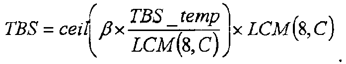
- In case 2: formula


-
FIG. 6A illustrates anexemplary simulation result 610 of link stability changes vs. MCS index, in accordance with this embodiment.FIG. 6A utilizes deltaSNR (i.e. ΔSNR ) to represent link stability with the TBS calculated and modified using the method in this embodiment to achieve a target BLER=10%. As shown inFIG. 6A , when the MCS index is low (e.g. between 0 and 10), the deltaSNR fluctuates between 0.6 and 1.2, less than the fluctuation in the same MCS range shown inFIG. 1B . -
FIG. 6B illustrates anexemplary simulation result 620 of SNR performance change vs. MCS index, in accordance with this embodiment. As shown inFIG. 6B , when the MCS index is low (e.g. between 0 and 10), the SNR curve is not so smooth as the SNR curve when the MCS index is high (e.g. between 20 and 28). As shown inFIG. 6B , given an MCS index range (e.g. between 0 and 10), the SNR curve corresponding to a lower PRB, e.g. when PRB=1, is not so smooth as the SNR curve corresponding to a higher PRB, e.g. when PRB=6, where a smoother SNR curve indicates a more stable link. - Table 6C below shows the TBS values calculated and corrected with the correction factor β based on the above mentioned method in the first embodiment, with the allocated resource

Table 6C MCS Index Qm PRB 1 2 3 4 5 6 0 2 16 40 72 96 128 152 1 2 24 64 96 136 168 208 2 2 32 80 120 168 216 256 3 2 48 104 160 224 280 336 4 2 64 128 200 272 344 416 5 2 80 168 256 344 432 520 6 2 96 200 304 408 512 616 7 2 112 232 352 480 600 720 8 2 128 272 408 552 688 832 9 2 144 304 464 624 776 936 10 4 144 304 464 624 776 936 11 4 160 336 512 688 864 1040 12 4 192 392 592 800 1000 1200 13 4 216 448 672 904 1128 1352 14 4 248 504 760 1016 1272 1528 15 4 272 560 848 1136 1424 1704 16 4 304 624 944 1264 1576 1896 17 6 304 624 944 1264 1576 1896 18 6 352 712 1072 1432 1792 2152 19 6 384 784 1184 1584 1984 2384 20 6 424 864 1304 1744 2184 2616 21 6 464 944 1416 1896 2376 2848 22 6 504 1016 1536 2048 2560 3080 23 6 544 1104 1656 2216 2768 3328 24 6 584 1184 1776 2376 2976 3568 25 6 624 1264 1896 2536 3168 3808 26 6 664 1336 2016 2688 3368 4032 27 6 696 1400 2104 2808 3512 4208 28 6 720 1456 2184 2920 3656 4376 - Table 6D below shows the simulated values of ΔSNR of adjacent MCSs, with the TBS values calculated and corrected with the correction factor β based on the above mentioned method in the first embodiment, the allocated resource

Table 6D PRB 1 2 3 4 5 6 ΔSNR I MCS 0 NaN NaN NaN NaN NaN NaN 1 0.882 0.9434 0.9743 0.9459 1.1174 1.1051 2 1.3666 1.0525 0.9866 0.9302 0.8929 0.9062 3 0.5966 0.9564 1.0075 1.1155 1.2236 1.1064 4 1.0352 1.0395 0.9661 0.9521 0.9512 0.996 5 0.8758 0.8822 1.1017 1.0529 1.0496 1.0664 6 1.2971 1.1215 0.9428 0.9689 0.9141 0.9764 7 0.6697 0.6795 0.8543 0.8507 0.946 09578 8 0.6752 0.9349 0.9246 0.9338 0.9039 0.8493 9 1.0346 0.8551 0.7767 0.7691 0.8518 0.8983 10 NaN NaN NaN NaN NaN NaN 11 0.9388 0.879 0.9649 0.9198 0.869 0.9092 12 0.7335 0.8537 0.8488 . 0.8222 0.8916 0.8522 13 0.9696 0.9846 0.8929 0.9243 0.9018 0.91 14 10189 0.9393 0.9285 0.978 0.9589 0.9497 15 09166 0.9384 1.0292 0.9518 1.0096 1.0164 16 1.0535 0.9027 0.9588 0.9697 0.9185 0.9621 17 NaN NaN NaN NaN NaN NaN 18 0.813 0.9208 0.7866 0.8594 0.9083 0.8108 19 0.8761 0.8589 0.9683 0.9294 0.9598 0.9798 20 0.9768 1.0166 1.0144 1.0278 1.0026 0.9999 21 0.9947 0.992 0.9195 0.9368 0.9457 0.9483 22 0.962 0.8876 1.0037 0.9546 0.9617 0.9879 23 0.9928 1.1357 1.0201 1.0584 0.9959 0.9943 24 0.9511 09426 0.9596 0.9489 1.0049 0.9808 25 1.0099 1.0097 0.9852 1.0005 0.9711 1.0125 26 1.061 09384 1.0496 1.0067 1.0731 1.026 27 1.0414 1.0513 0.9398 0.9866 0.9268 0.9365 28 0.9567 1.0495 1.031 1.0579 1.0838 1.0464 - In a second embodiment, the functional model for TBS calculation is: TBS=F(NRE ), with a specific form shown as follows:

- In the above formula, NRE represents the number of REs allocated, i.e.

- In a first situation, when the total number of REs is small and the MCS modulation order is low, the total number of REs is set to be the minimum value or any other value of the RE set after quantization. For example, the RE set after quantization is SY={120, 126, 132...}, then 120 is taken as the total number of REs calculated by TBS. In a second situation, when the total number of REs is high or the MCS modulation order is high, the total number of REs is set to be the total number of REs calculated by the allocated parameters, that is,

- According to one example, the total number of REs is set in the following table:
Qm Slower_MCS Shigher_MCS NRE NRE ≤ x NRE (a value in SY) NRE > x NRE NRE - The functional model of the total number of REs is shown below:

- In the above, the value of x is generally 280; Slower_MCS represents a set of Qm values for a lower-order MCS. For example, Slower_MCS = {2,4}, i.e. the value of Qm may be 2 or 4. SY is a collection of values for Y, for example SY = {120,126,132,...}; min (SY) represents the minimum value in the set of values of Y.
- The steps to determine TBS in this embodiment include the following:
-
Step 1, according to the obtained transmission parameters Qm,R, v, Y and
-
Step 2, based on Qm ×R×v×NRE , calculate and round up to obtain TBS_temp. The TBS_temp includes the transport block CRC check bits (TB_CRC). -
Step 3, the TBS_temp is divided into blocks according to the code block segmentation rule of the channel coding. Assuming that the number of divided code blocks is C, to ensure that the TBS bytes are aligned and the sizes of the divided code blocks are equal, the TBS_temp needs to be divisible by the LCM (8, C). The formula for this process is as follows
-
FIG. 7A illustrates anexemplary simulation result 710 of link stability changes vs. MCS index, in accordance with this embodiment.FIG. 7A utilizes deltaSNR (i.e. ΔSNR ) to represent link stability with the TBS calculated and modified using the method in this embodiment to achieve a target BLER=10%. As shown inFIG. 7A , when the MCS index is low (e.g. between 0 and 10), the deltaSNR fluctuates between 0.6 and 1.5, less than the fluctuation in the same MCS range shown inFIG. 1B . -
FIG. 7B illustrates anexemplary simulation result 720 of SNR performance change vs. MCS index, in accordance with this embodiment. As shown inFIG. 7B , when the MCS index is low (e.g. between 0 and 10), the SNR curve is not so smooth as the SNR curve when the MCS index is high (e.g. between 20 and 28). As shown inFIG. 7B , given an MCS index range (e.g. between 0 and 10), the SNR curve corresponding to a lower PRB, e.g. when PRB=1, is not so smooth as the SNR curve corresponding to a higher PRB, e.g. when PRB=6, where a smoother SNR curve indicates a more stable link. - Table 7C below shows the TBS values calculated based on the above mentioned method in the second embodiment, with the new RE value constraint NRE =120.
Table 7C MCS Index Qm PRB 1 2 3 4 5 6 0 2 16 48 72 104 128 160 1 2 24 64 96 136 168 208 2 2 32 80 120 168 216 256 3 2 48 104 168 224 280 344 4 2 64 136 208 280 352 424 5 2 80 168 256 344 432 520 6 2 96 200 304 408 512 616 7 2 112 232 360 480 600 728 8 2 12B 272 408 552 696 832 9 2 144 304 464 624 784 944 10 4 144 304 464 624 784 944 11 4 168 344 520 696 872 1048 12 4 192 392 600 800 1008 1208 13 4 216 448 680 904 1136 1368 14 4 248 504 768 1024 1288 1544 15 4 280 568 856 1144 1432 1720 16 4 296 508 912 1224 1528 1840 17 6 296 608 912 1224 1528 1840 18 6 312 640 968 1296 . 1624 1952 19 6 352 712 1080 1440 1800 2168 20 6 384 784 1184 1584 1984 2384 21 6 424 856 1288 1720 2152 2592 22 6 456 928 1392 1864 2328 2800 23 6 496 1000 1504 2008 2512 3024 24 6 528 1072 1616 2160 2704 3248 25 6 568 1144 1720 2304 2880 3456 26 6 600 1216 1832 2440 3056 3672 27 6 632 1272 1912 2552 3192 3824 28 6 656 1320 1984 2656 3320 3976 - Table 7D below shows the simulated values of ΔSNR of adjacent MCSs, with the TBS values calculated based on the above mentioned method in the second embodiment, with the new RE value constraint

Table 7D PRB 1 2 3 4 5 6 ΔSNR I MCS 0 NaN NaN NaN NaN NaN NaN 1 0.9395 0.9991 0.9941 1.0927 1.0634 1.0445 2 0.6133 0.7165 0.8077 0.7349 0.9629 0.7704 3 1.4353 0.9961 1.425 1.2235 1.114 1.2909 4 0.9522 1.082 0.9337 1.0087 1.0691 0.9922 5 0.9507 0.9945 0.9161 1.0164 1.0182 1.0252 6 0.8129 0.9562 0.9854 0.9 09077 0.947 7 0.779 0 8148 0.9742 0.937 09459 0.9895 8 0.8754 0.9602 0.729 0.9308 0.9566 0.8835 9 0.6579 0.8066 0.9538 0.8757 0.8866 0.9261 10 NaN NaN NaN NaN NaN NaN 11 0.8816 0.7628 0.7236 0.701 0.6642 0.6828 12 0.7783 0.8063 0.9026 0.8606 0.9443 0.8973 13 08709 09668 08987 0.8787 08811 09138 14 1 0217 0.8844 0 9758 0.9619 0.9731 0.9531 15 1.0197 1.0427 0.9511 1.0282 0.9549 0.9805 16 0.5405 0.656 0.6022 0.6477 0.6221 06473 17 NaN NaN NaN NaN NaN NaN 18 0.434 0.4394 0.5284 0.4999 0.5586 05556 19 1.0579 0.9871 1.0226 1.0412 0.9797 1.0054 20 0.8967 0.9857 0.9636 0.96 1.0236 1.0035 21 1.1022 0.9963 0.9381 0.9424 0.9095 0.9463 22 0.837 0.9637 0.9214 0.9688 0.943 09515 23 1.0724 1.0106 1.0391 1.014 1.0355 1.0252 24 0.8719 0.9567 0.9895 0.9685 1.0087 0.9627 25 1.0593 0.9947 0.9792 1.0231 0.9781 0.9634 26 0.9921 1.0381 1.0595 0.9889 1.0206 1.0489 27 1.0388 0.9775 0.9344 0.9696 0.9725 08906 28 1.0985 1.0231 1.0326 1.1254 1.0628 1.1204 - In a third embodiment, the functional model for TBS calculation is: TBS = F(R), with a specific form shown as follows:

- In the above formula, the code rate R is a function of (a) the number of PRBs allocated for the downlink or uplink, and (b) the order of the modulation and coding Qm; function(•) indicates rounding, rounding up, rounding down, or retaining the original value; Y is the quantized value of X that is the number of REs per PRB; δ is the quantization step of the TBS. The modification on the code rate R or the spectrum efficiency SE is mainly to improve the link stability when the PRB is small and the order of the MCS is low. The modified value of R or SE can be determined according to the following two situations.
- In a first situation, when the number of PRBs is small, or the modulation order of MCS is low, or the modulation order of MCS is high but at the SE overlap (where the SE value does not change from an MCS index to an adjacent MCS index in the MCS table), the code rate R or spectrum efficiency SE in the MCS table is corrected to obtain R' or SE'. In this case, R' or SE' is used to calculate the code rate or spectrum efficiency of the TBS. For example, when the IMCS in the downlink 64QAM MCS table is 0~17, the value of R' may be {0.1064, 0.1387, 0.1816, 0.2227,0.2734, 0.3359, 0.3984, 0.4668, 0.5342, 0.6025, 0.3018, 0.3359, 0.3857, 0.4346, 0.4912, 0.5469, 0.6055, 0.4033}, or the value of SE' may be {0.2131, 0.2779, 0.3627, 0.4448 , 0.5469, 0.6721, 0.7973, 0.9331, 1.0689, 1.2056, 1.2056, 1.3424, 1.5412, 1.7401, 1.9638, 2.1818, 2.42, 2.42}. In a second situation, when the number of PRBs is large, or the MCS modulation order is high but not at the SE overlap (where the SE value does not change from an MCS index to an adjacent MCS index in the MCS table), the corresponding code rate R in the MCS table is used to calculate the TBS.
- The functional model of the code rate R is shown below:
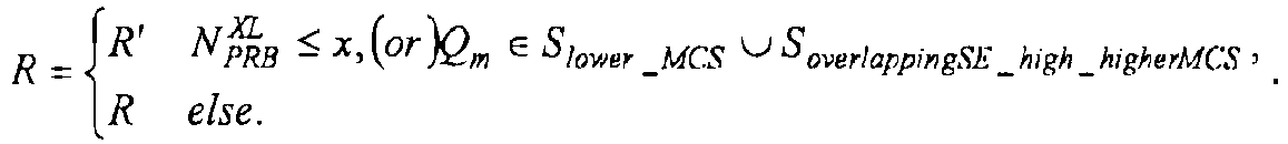
- The functional model of the spectral efficiency SE is shown below:
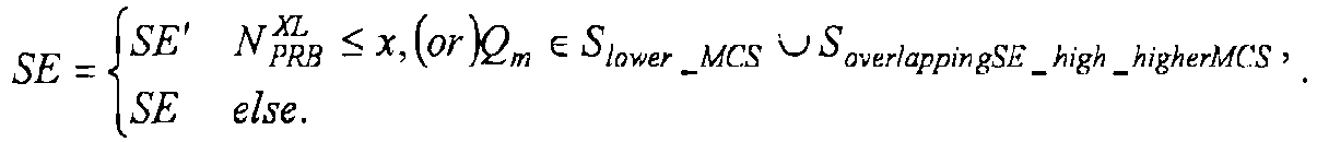
- According to one example, the values of code rate and spectral efficiency are set in the following table, for a downlink 64 QAM:
MCS Index IMCS Modulation Order Qm CodeRate*1024 R CodeRate*1024 R' SE SE' 0 2 120 109 0.2344 0.2131 1 2 157 142 0.3057 0.2779 2 2 193 186 0.377 0.3627 3 2 251 228 0.4893 0.4448 4 2 308 280 0.6016 0.5469 5 2 379 344 0.7393 0.6721 6 2 449 408 0.877 0.7973 7 2 526 478 1.0264 0.9331 8 2 602 547 1.1758 1.0689 9 2 679 617 1.3262 1.2056 10 4 340 309 1.3262 1.2056 11 4 378 344 1.4766 1.3424 12 4 434 395 1.69535 1.5412 13 4 490 445 1.9141 1.7401 14 4 553 503 2.1602 1.9638 15 4 616 560 2.4063 2.1875 16 4 658 620 2.5684 2.42 17 6 438 413 2.5684 2.42 18 6 466 466 2.7305 2.7305 19 6 517 517 3.0264 3.0264 20 6 567 567 3.3223 3.3223 21 6 616 616 3.6123 3.6123 22 6 666 666 3.9023 3.9023 23 6 719 719 4.21285 4.21285 24 6 772 772 4.5234 4.5234 25 6 822 822 4.8193 4.8193 26 6 873 873 5.1152 5.1152 27 6 910 910 5.33495 5.33495 28 6 948 948 5.5547 5.5547 - The steps to determine TBS in this embodiment include the following:
-
Step 1, according to the obtained transmission parameters Qm , R, v, Y and
-
Step 2, based on Qm ×R×v×NRE , calculate and round up to obtain TBS_temp. The TBS_temp includes the transport block CRC check bits (TB_CRC). -
FIG. 8A illustrates anexemplary simulation result 810 of link stability changes vs. MCS index, in accordance with this embodiment.FIG. 8A utilizes deltaSNR (i.e. ΔSNR) to represent link stability with the TBS calculated and modified using the method in this embodiment to achieve a target BLER=10%. As shown inFIG. 8A , when the MCS index is low (e.g. between 0 and 10), the deltaSNR fluctuates between 0.6 and 1.2, less than the fluctuation in the same MCS range shown inFIG. 1B . -
FIG. 8B illustrates anexemplary simulation result 820 of SNR performance change vs. MCS index, in accordance with this embodiment. As shown inFIG. 8B , when the MCS index is low (e.g. between 0 and 10), the SNR curve is not so smooth as the SNR curve when the MCS index is high (e.g. between 20 and 28). As shown inFIG. 8B , given an MCS index range (e.g. between 0 and 10), the SNR curve corresponding to a lower PRB, e.g. when PRB=1, is not so smooth as the SNR curve corresponding to a higher PRB, e.g. when PRB=6, where a smoother SNR curve indicates a more stable link. - Table 8C below shows the TBS values calculated based on a modified code rate R or modified spectral efficiency SE as in the above mentioned method in the third embodiment, with allocated

Table 8C MCS Index Qm PRB 1 2 3 4 5 6 0 2 16 48 72 104 128 160 1 2 24 64 96 136 168 208 2 2 32 80 128 176 224 272 3 2 48 104 168 224 280 344 4 2 64 136 208 280 352 424 5 2 80 168 256 344 432 520 6 2 96 200 304 408 512 616 7 2 112 232 360 480 600 728 8 2 128 272 408 552 696 832 9 2 144 304 464 624 784 944 10 4 144 304 464 624 784 944 11 4 168 344 520 696 872 1048 12 4 192 392 600 800 1008 1208 13 4 216 448 680 904 1136 1368 14 4 248 504 768 1024 1288 1544 15 4 280 568 856 1144 1432 1720 16 4 304 624 944 1264 1584 1904 17 6 304 624 944 1264 1584 1904 18 6 352 712 1072 1432 1792 2152 19 6 384 784 1184 1584 1984 2384 20 6 424 864 1304 1744 2184 2616 21 6 464 944 1416 1896 2376 2848 22 6 504 1016 1536 2048 2560 3080 23 6 544 1104 1656 2216 2768 3328 24 6 584 1184 1776 2376 2976 3568 25 6 624 1264 1896 2536 3168 3808 26 6 664 1336 2016 2688 3368 4032 27 6 696 1400 2104 2808 3512 4208 28 6 720 1456 2184 2920 3656 4376 - Table 8D below shows the simulated values of ΔSNR of adjacent MCSs, with the TBS values calculated based on a modified code rate R or modified spectral efficiency SE as in the above mentioned method in the third embodiment, with allocated

Table 8D PRB 1 2 3 4 5 6 ΔSNR I MCS 0 NaN NaN NaN NaN NaN NaN 1 0.882 0.9434 0.9213 0.996 1.0212 0.9661 2 0.7658 0.7567 1.0603 1.0174 1.1137 1.0485 3 1.1974 0.9617 1.0792 0.96 0.9327 1.0026 4 1.0352 1.0764 0.9073 0.9875 1.0266 0.9327 5 0.8758 0.9483 0.9703 0.9642 1.0073 1.0038 6 0.8268 0.835 0.9042 0.8773 0.8957 0.9178 7 0.8041 0.8154 0.9184 0.914 09221 0.9506 8 0.6638 0.9624 0.7668 0.8405 0.8798 0.8394 9 0.7761 0.694 0.7997 0.8255 0.8129 0.847 10 NaN NaN NaN NaN NaN NaN 11 0.7961 0.7589 0.7405 0.6579 06614 0.6727 12 0.7447 0.7418 0.8569 0.8696 0.8991 0.9025 13 0.7499 0.894 0.8251 0.7926 0.7785 0.7902 14 0.9938 0.9008 0.8692 0.8843 0.934 0.908 15 1.0215 0.9328 0.9152 0.9306 0.8767 0.8832 16 0.6453 0.784 0.853 0.904 0.9093 0.9421 17 NaN NaN NaN NaN NaN NaN 18 12379 1.1929 1.1195 1.1073 1.1307 1.0974 19 0.8761 0.8589 0.9683 0.9294 0.9598 0.9798 20 0.9768 1.0166 1 1.0144 1.0278 1.0026 0.9999 21 0.9947 0.992 0.9195 0.9368 0.9457 0.9483 22 0.962 0.8876 1.0037 0.9546 0.9617 0.9879 23 0.9928 1.1357 1.0201 1.0584 0.9959 0.9943 24 0.9511 0.9426 0.9596 0.9489 1.0049 0.9808 25 1.0099 1.0097 0.9852 1.0005 0.9711 1.0125 26 1.061 0.9384 1.0496 1.0067 1.0731 1.026 27 1.0414 1.0513 0.9398 0.9866 0.9268 0.9365 28 0.9567 1.0495 1.031 1.0579 1.0838 1.0464 - In a fourth embodiment, after the TBS is calculated by using a formula, e.g. an existing formula or a formula according to any one of the above embodiments, if any one of the parameters in the formula changes, the calculated TBS will change. For example, the parameter allocated during the initial pass is: Qm = 2, R=308/1024, the number of PRB is 2, the number of REs per PRB is 132, and the TBS is 120. Then the parameters allocated for retransmission are: Qm = 2, R = 379/1024, the number of PRB is 2, the number of REs per PRB is 132, and the TBS is 176. Because the two calculated TBSs are different, the transmission cannot be continued. In response to this problem, in consideration that the transport block size is the same during initial transmission and retransmission, the TBS is quantized in this embodiment. The quantization step size increases when TBS increase, which can both ensure that the TBS granularity for transmission is good, and ensure that the TBS is the same in initial transmission and retransmission.
- The function of the quantization step is as follows:
step = 2 n, 3 ≤ n ≤ 10 and n is integer. - Taking the value interval of TBS (including CRC check bits) less than 8448 as an example, the set of TBSs that have been verified to be useable is [40: 8: 512, 528: 16: 1024, 1056: 32: 2048, 2048 + 64:64:6144, 6144 + 128: 128: 8448]. After searching the calculated TBS, the new value interval is obtained as [32: 8: 512, 528: 16: 992, 1024: 32: 2048, 2176: 64 : 6144, 6272: 128: 8192]. Here, 40: 8: 512, for example, represents a set of values between 40 and 512, with an interval of 8. Simulation results show that when the number of REs is 132, after calculating the intermediate TBS, it is also applicable to take the closest larger TBS from this interval as the actual transmitted TBS.
- According to the calculated TBS, it can be known that to ensure the consistency of the TBS in initial transmission and retransmission, the value of the TBS may also be constrained by the number of PRBs and the order of MCS. That is, the quantization step may also be a function of: the number of PRBs, and/or the MCS order, and/or Spectral efficiency (SE) and/or the code rate. For example, when the number of PRBs is less than 3 and the order of MCS is 2, the TBS may have a fixed quantization step of 8; when the number of PRBs is greater than 100, the order of MCS is 6, and the code rate is greater than 8/9, the quantization step may be 512. In this way, the scheduling range of the PRB or IMCS at the initial transmission and retransmission can be expanded, and the TBSs in the initial transmission and the retransmission can obtain the same value in this range.
-
FIG. 9 illustrates anexemplary simulation result 910 of SNR performance change vs. MCS index, in accordance with this embodiment. As shown in FIG. 98B, when the MCS index is low (e.g. between 0 and 10), the SNR curve is not so smooth as the SNR curve when the MCS index is high (e.g. between 20 and 28). As shown inFIG. 9B , given an MCS index range (e.g. between 0 and 10), the SNR curve corresponding to a lower PRB, e.g. when PRB=1, is not so smooth as the SNR curve corresponding to a higher PRB, e.g. when PRB=6, where a smoother SNR curve indicates a more stable link. - Table 9 below shows the TBS values calculated based on a useable TBS set as in the above mentioned method in the fourth embodiment, with allocated

Table 9 MCS Index Qm PRB 1 2 3 4 5 6 0 2 24 48 80 112 144 176 1 2 32 72 112 152 192 232 2 2 40 88 136 184 240 288 3 2 56 120 184 248 312 376 4 2 64 144 224 304 384 464 5 2 88 184 280 376 472 576 6 2 104 216 336 448 576 688 7 2 120 256 392 528 672 800 8 2 144 296 456 608 768 928 9 2 160 336 512 688 864 1040 10 4 160 336 512 688 864 1040 11 4 184 376 576 768 960 1168 12 4 208 432 656 880 1104 1328 13 4 240 496 752 1008 1264 1520 14 4 272 560 848 1136 1424 1712 15 4 304 624 944 1264 1584 1904 16 4 328 672 1008 1360 1680 2032 17 6 328 672 1008 1360 1680 2032 18 6 352 720 1072 1456 1808 2160 19 6 384 784 1200 1584 2000 2416 20 6 424 864 1328 1744 2224 2672 21 6 464 944 1424 1904 2416 2864 22 6 512 1040 1552 2096 2608 3120 23 6 544 1104 1680 2224 2800 3376 24 6 592 1200 1776 2416 2992 3568 25 6 624 1264 1904 2544 3184 3824 26 6 672 1360 2032 2736 3376 4072 27 6 704 1424 2160 2864 3568 4264 28 6 720 1456 2224 2928 3696 4392 - In a fifth embodiment, after the TBS is calculated by using a formula, e.g. an existing formula or a formula according to any one of the above embodiments, the UE or BS selects, from a quantized TBS set, a TBS that is closest to the calculated TBS as the final TBS for transmission. The elements {TBSi, i=1,2, ......} in the quantized TBS set satisfy at least one of the following conditions.
- In accordance with
Condition 1, each element TBS, satisfies: TBS¡ mod 8 =0, TBSi mod

- In accordance with
Condition 2, each element TBS¡ satisfies: TBS¡ mod 8 =0, TBSi mod


- In accordance with
Condition 3, each element TBS¡ is less than or equal to 8424, each element TBS, belongs to the information bit set {24:8:496, 512:16:1008, 1040:32:2032, 2096:64:3824, 3880:64:6120, 6248:128:7656, 8040, 8424}. - In accordance with Condition 4, when TBS¡ is less than or equal to a threshold Kthreshold, (TBSLTE - TBSNR)/TBSNR < 0.2; and when TBS, is greater than the threshold Kthreshold, (TBSLTE - TBSNR)/TBSNR < 0.05. Here, Kthreshold is a value from the range {Kthreshold | Kmin <Kthreshold< Kmax}, Kmin is an integer between 10 and 100, Kmax is an integer greater than 10000. For example, Kthreshold = 1000. TBSLTE is the TBS set defined for a Long Term Evolution (LTE) system; TBSNR is the TBS set defined under this embodiment, i.e. a TBS set to be defined for a NR system based on eMBB.
- In accordance with Condition 5, generating a first ordered sequence including integers that are between Kmin and Kmin, and satisfy
Condition 1 orCondition 2; generating a second ordered sequence including integers that are between Kmin and Kmin, and are predefined for a LTE system; quantizing the first ordered sequence according to the second ordered sequence to generate the third sequence; and the quantized set in this embodiment includes all elements in the third sequence. Kmin is an integer between 10 and 100, and Kmax is an integer greater than 10000. For example, Kthreshold =1000. - In one example, the quantization process includes the following steps. First, traverse to get a first sequence TBS Sequencex satisfying the
Condition 1. Then, using the LTE TBS sequence as a second sequence, compare the elements TBSi LTE in the second sequence with all the elements in the first sequence TBS Sequencex to find the TBSj x in the first sequence that is equal to or rounding to or rounding up to or rounding down to a value TBSi LTE , and replace the original element TBSi LTE with the TBSj x to obtain the third TBS sequence. The quantized set of TBSs shall include at least all the elements in the third TBS Sequence. - For example, a
sequence satisfying Condition 1 and including integers from 16 to 512 is taken as the first sequence, and all the elements in the first sequence are as follows: {16 24 32 40 48 56 64 72 80 88 96 104 112 120 128 136 144 152 160 168 176 184 192 200 208 216 224 232 240 248 256 264 272 280 288 296 304 312 320 328 336 344 352 360 368 376 384 392 400 408 416 424 432 440 448 456 464 472 480 488 496 504 512}. All LTE TBSs from 16 to 512 form the second sequence in descending order, where the elements of the second sequence are as follows: {16 24 32 40 56 72 88 104 120 136 144 152 176 208 224 256 280 288 296 328 336 344 376 392 408 424 440 456 472 488 504}. The first sequence is quantized according to the second sequence, which is divided into three quantization methods. Each quantization method obtains a third sequence. During the process of obtaining the third sequence, the quantization method should be consistent. For example, if thesecond element 24 in the second sequence is compared with each element in the first sequence, and according to the closest element rule, 24 in the first sequence is quantized to be the second element in the third sequence; if thesecond element 24 in the second sequence is compared with each element in the first sequence, and according to the closest but larger element rule, a larger element value is quantized to obtain 32 in the first sequence as the second element in the third sequence; if thesecond element 24 in the second sequence is compared with each element in the first sequence, and according to the closest but smaller element rule, a smaller element value is quantized to obtain 16 in the first sequence as the second element in the third sequence; and so on and so forth until the elements in the second sequence are quantified, then three third sequences in descending order are obtained. - According to the first quantization method, the element in the first sequence closest to the second sequence is found, and the third sequence obtained is as follows: {16 24 32 40 56 72 88 104 120 136 144 152 176 208 224 256 280 288 296 328 336 344 376 392 408 424 440 456 472 488 504}. According to the second quantization method, the element in the first sequence that is closest and larger than the second sequence is found, and the third sequence obtained is as follows: {24 32 40 48 56 64 80 96 112 128 144 152 160 184 232 264 288 296 304 336 344 352 384 400 416 432 448 464 480 496 512}. According to the third quantization method, the element in the first sequence that is closest and smaller than the element in the second sequence is found, and the third sequence obtained is as follows: {16 24 32 40 64 80 96 112 128 136 144 168 200 216 248 272 280 288 320 328 336 368 384 400 416 432 448 464 480 496}.
- The set of quantized TBSs includes at least all the elements in the third sequence. For example, if the third sequence is a set of quantization TBSs, the resource or transmission parameters are: the modulation order Qm = 2, the code rate R = 0.5132, the layer number is 1, the number of PRBs is 1, and the number of REs per PRB is 128, rounding up to calculate an intermediate TBS of 132, the nearest neighbor relative to the intermediate TBS is 136 (or a larger value of 136, or a smaller value of 120) is selected as a quantized TBS according to the third sequence to be taken as the actual transmitted TBS.
- In one example, suppose the third TBS sequence obtained from the first sequence satisfy the
Condition 1. When an unquantized first sequence is taken as a quantized TBS table and referred to as TBS Sequence1, the distribution of the quantized TBS in the PDSCH 64 QAM-MCS table and a comparison with the LTE TBS table is shown inFIG. 10A . When the third TBS Sequence is taken as a quantized TBS table1, the distribution of the quantized TBS in the PDSCH 64 QAM-MCS table and a comparison with the LTE TBS table is shown inFIG. 10B . - In another example, suppose the third TBS sequence obtained from the first sequence satisfy the
Condition 2. When an unquantized first sequence is taken as a quantized TBS table and referred to as TBS Sequence2, the distribution of the quantized TBS in the PDSCH 64 QAM-MCS table and a comparison with the LTE TBS table is shown inFIG. 11A . When the third TBS Sequence is taken as a quantized TBS table2, the distribution of the quantized TBS in the PDSCH 64 QAM-MCS table and a comparison with the LTE TBS table is shown inFIG. 11B . - In yet another example, suppose the third TBS sequence obtained from the first sequence satisfy the
Condition 3. When an unquantized first sequence is taken as a quantized TBS table and referred to as TBS Sequence3, the distribution of the quantized TBS in the PDSCH 64 QAM-MCS table and a comparison with the LTE TBS table is shown inFIG. 12A . When the third TBS Sequence is taken as a quantized TBS table3, the distribution of the quantized TBS in the PDSCH 64 QAM-MCS table and a comparison with the LTE TBS table is shown inFIG. 12B . - While various embodiments of the present disclosure have been described above, it should be understood that they have been presented by way of example only, and not by way of limitation. Likewise, the various diagrams may depict an example architectural or configuration, which are provided to enable persons of ordinary skill in the art to understand exemplary features and functions of the present disclosure. Such persons would understand, however, that the present disclosure is not restricted to the illustrated example architectures or configurations, but can be implemented using a variety of alternative architectures and configurations. Additionally, as would be understood by persons of ordinary skill in the art, one or more features of one embodiment can be combined with one or more features of another embodiment described herein. Thus, the breadth and scope of the present disclosure should not be limited by any of the above-described exemplary embodiments.
- It is also understood that any reference to an element herein using a designation such as "first," "second," and so forth does not generally limit the quantity or order of those elements. Rather, these designations can be used herein as a convenient means of distinguishing between two or more elements or instances of an element. Thus, a reference to first and second elements does not mean that only two elements can be employed, or that the first element must precede the second element in some manner.
- Additionally, a person having ordinary skill in the art would understand that information and signals can be represented using any of a variety of different technologies and techniques. For example, data, instructions, commands, information, signals, bits and symbols, for example, which may be referenced in the above description can be represented by voltages, currents, electromagnetic waves, magnetic fields or particles, optical fields or particles, or any combination thereof.
- A person of ordinary skill in the art would further appreciate that any of the various illustrative logical blocks, modules, processors, means, circuits, methods and functions described in connection with the aspects disclosed herein can be implemented by electronic hardware (e.g., a digital implementation, an analog implementation, or a combination of the two), firmware, various forms of program or design code incorporating instructions (which can be referred to herein, for convenience, as "software" or a "software module), or any combination of these techniques.
- To clearly illustrate this interchangeability of hardware, firmware and software, various illustrative components, blocks, modules, circuits, and steps have been described above generally in terms of their functionality. Whether such functionality is implemented as hardware, firmware or software, or a combination of these techniques, depends upon the particular application and design constraints imposed on the overall system. Skilled artisans can implement the described functionality in various ways for each particular application, but such implementation decisions do not cause a departure from the scope of the present disclosure. In accordance with various embodiments, a processor, device, component, circuit, structure, machine, module, etc. can be configured to perform one or more of the functions described herein. The term "configured to" or "configured for" as used herein with respect to a specified operation or function refers to a processor, device, component, circuit, structure, machine, module, etc. that is physically constructed, programmed and/or arranged to perform the specified operation or function.
- Furthermore, a person of ordinary skill in the art would understand that various illustrative logical blocks, modules, devices, components and circuits described herein can be implemented within or performed by an integrated circuit (IC) that can include a general purpose processor, a digital signal processor (DSP), an application specific integrated circuit (ASIC), a field programmable gate array (FPGA) or other programmable logic device, or any combination thereof. The logical blocks, modules, and circuits can further include antennas and/or transceivers to communicate with various components within the network or within the device. A general purpose processor can be a microprocessor, but in the alternative, the processor can be any conventional processor, controller, or state machine. A processor can also be implemented as a combination of computing devices, e.g., a combination of a DSP and a microprocessor, a plurality of microprocessors, one or more microprocessors in conjunction with a DSP core, or any other suitable configuration to perform the functions described herein.
- If implemented in software, the functions can be stored as one or more instructions or code on a computer-readable medium. Thus, the steps of a method or algorithm disclosed herein can be implemented as software stored on a computer-readable medium. Computer-readable media includes both computer storage media and communication media including any medium that can be enabled to transfer a computer program or code from one place to another. A storage media can be any available media that can be accessed by a computer. By way of example, and not limitation, such computer-readable media can include RAM, ROM, EEPROM, CD-ROM or other optical disk storage, magnetic disk storage or other magnetic storage devices, or any other medium that can be used to store desired program code in the form of instructions or data structures and that can be accessed by a computer.
- In this document, the term "module" as used herein, refers to software, firmware, hardware, and any combination of these elements for performing the associated functions described herein. Additionally, for purpose of discussion, the various modules are described as discrete modules; however, as would be apparent to one of ordinary skill in the art, two or more modules may be combined to form a single module that performs the associated functions according embodiments of the present disclosure.
- Additionally, memory or other storage, as well as communication components, may be employed in embodiments of the present disclosure. It will be appreciated that, for clarity purposes, the above description has described embodiments of the present disclosure with reference to different functional units and processors. However, it will be apparent that any suitable distribution of functionality between different functional units, processing logic elements or domains may be used without detracting from the present disclosure. For example, functionality illustrated to be performed by separate processing logic elements, or controllers, may be performed by the same processing logic element, or controller. Hence, references to specific functional units are only references to a suitable means for providing the described functionality, rather than indicative of a strict logical or physical structure or organization.
- Various modifications to the implementations described in this disclosure will be readily apparent to those skilled in the art, and the general principles defined herein can be applied to other implementations without departing from the scope of this disclosure. Thus, the disclosure is not intended to be limited to the implementations shown herein, but is to be accorded the widest scope consistent with the novel features and principles disclosed herein, as recited in the claims below.
Claims (13)
- A method performed by a wireless communication device, the method comprising:receiving (302) control information from a wireless communication node, wherein the control information includes a plurality of transmission parameters related to transport blocks to be transmitted between the wireless communication device and the wireless communication node;calculating (304) an intermediate transport block size, TBS, for the transport blocks based on the plurality of transmission parameters;modifying (306) the intermediate TBS to generate a modified TBS in response to an event that the intermediate TBS is smaller than a threshold; anddetermining (308) a final TBS for the transport blocks based on a TBS that is closest to the modified TBS, among TBSs that are in a quantized set and not smaller than the modified TBS.
- The method of claim 1, wherein the plurality of transmission parameters comprises:a modulation order configured for transmission of the transport blocks;a code rate configured for transmission of the transport blocks; anda quantity of physical resource blocks configured for transmission of the transport blocks.
- The method of claim 1 or 2, wherein modifying the intermediate TBS comprises:determining a correction factor based on the quantity of physical resource blocks, the modulation order and the code rate; andmodifying the intermediate TBS based on the correction factor to generate the modified TBS.
- The method of any one of claims 1 to 3, wherein calculating the intermediate TBS comprises:calculating a multiplication product of: the modulation order, the code rate, the quantity of physical resource blocks, and a quantity of layers configured for transmission of the transport blocks; andusing the multiplication product as the intermediate TBS.
- The method of any one of claims 1 or 2, wherein modifying the intermediate TBS comprises:dividing the intermediate TBS by a quantization step to generate a quotient;rounding down the quotient to generate a first integer;multiplying the first integer by the quantization step to generate the modified TBS.
- A method performed by a wireless communication node, the method comprising:generating (502) a plurality of transmission parameters related to transport blocks;transmitting (510) control information that comprises the plurality of transmission parameters;calculating (504) an intermediate transport block size, TBS, for the transport blocks based on the plurality of transmission parameters;modifying (506) the intermediate TBS to generate a modified TBS in response to an event that the intermediate TBS is smaller than a threshold;determining (508) a final TBS for the transport blocks based on a TBS that is closest to the modified TBS, among TBSs that are in a quantized set and not smaller than the modified TBS; andcommunicating (510) with a wireless communication device using the transport blocks based on the final TBS.
- The method of claim 6, wherein the plurality of transmission parameters comprises:a modulation order configured for transmission of the transport blocks;a code rate configured for transmission of the transport blocks; anda quantity of physical resource blocks configured for transmission of the transport blocks.
- The method of claim 6 or 7, wherein modifying the intermediate TBS comprises:determining a correction factor based on the quantity of physical resource blocks, the modulation order and the code rate; andmodifying the intermediate TBS based on the correction factor to generate the modified TBS.
- The method of any one of claims 6 to 8, wherein calculating the intermediate TBS comprises:calculating a multiplication product of: the modulation order, the code rate, the quantity of physical resource blocks, and a quantity of layers configured for transmission of the transport blocks; andusing the multiplication product as the intermediate TBS.
- The method of any one of claims 6 or 7, wherein modifying the intermediate TBS comprises:dividing the intermediate TBS by a quantization step to generate a quotient;rounding down the quotient to generate a first integer;multiplying the first integer by the quantization step to generate the modified TBS.
- A first communication apparatus comprising a processor and a memory, wherein the memory stores instructions that, when executed, causes the processor to implement a method recited in any of claims 1 to 5.
- A first communication apparatus comprising a processor and a memory, wherein the memory stores instructions that, when executed, causes the processor to implement a method recited in any of claims 6 to 10.
- A non-transitory computer-readable medium having computer-executable instructions stored thereon, the computer-executable instructions, when executed by a processor, causing the processor to implement a method recited in any of claims 1 to 10.
Priority Applications (1)
| Application Number | Priority Date | Filing Date | Title |
|---|---|---|---|
| EP21172439.8A EP3913828B1 (en) | 2017-11-17 | 2017-11-17 | Methods, apparatus and systems for determining a transport block size in a wireless communication |
Applications Claiming Priority (1)
| Application Number | Priority Date | Filing Date | Title |
|---|---|---|---|
| PCT/CN2017/111730 WO2019095315A1 (en) | 2017-11-17 | 2017-11-17 | Methods, apparatus and systems for determining a transport block size in a wireless communication |
Related Child Applications (1)
| Application Number | Title | Priority Date | Filing Date |
|---|---|---|---|
| EP21172439.8A Division EP3913828B1 (en) | 2017-11-17 | 2017-11-17 | Methods, apparatus and systems for determining a transport block size in a wireless communication |
Publications (3)
| Publication Number | Publication Date |
|---|---|
| EP3577874A1 EP3577874A1 (en) | 2019-12-11 |
| EP3577874A4 EP3577874A4 (en) | 2020-03-04 |
| EP3577874B1 true EP3577874B1 (en) | 2021-05-12 |
Family
ID=66539310
Family Applications (2)
| Application Number | Title | Priority Date | Filing Date |
|---|---|---|---|
| EP17932502.2A Active EP3577874B1 (en) | 2017-11-17 | 2017-11-17 | Methods, apparatus and systems for determining a transport block size in a wireless communication |
| EP21172439.8A Active EP3913828B1 (en) | 2017-11-17 | 2017-11-17 | Methods, apparatus and systems for determining a transport block size in a wireless communication |
Family Applications After (1)
| Application Number | Title | Priority Date | Filing Date |
|---|---|---|---|
| EP21172439.8A Active EP3913828B1 (en) | 2017-11-17 | 2017-11-17 | Methods, apparatus and systems for determining a transport block size in a wireless communication |
Country Status (9)
| Country | Link |
|---|---|
| US (4) | US10880888B2 (en) |
| EP (2) | EP3577874B1 (en) |
| JP (1) | JP7071500B2 (en) |
| KR (1) | KR102445007B1 (en) |
| CN (2) | CN114006676B (en) |
| ES (2) | ES3035667T3 (en) |
| FI (1) | FI3913828T3 (en) |
| PT (1) | PT3577874T (en) |
| WO (1) | WO2019095315A1 (en) |
Cited By (1)
| Publication number | Priority date | Publication date | Assignee | Title |
|---|---|---|---|---|
| US20240113808A1 (en) * | 2017-06-15 | 2024-04-04 | Samsung Electronics Co., Ltd. | Method and apparatus for performing channel coding and decoding in communication or broadcasting system |
Families Citing this family (11)
| Publication number | Priority date | Publication date | Assignee | Title |
|---|---|---|---|---|
| KR102414531B1 (en) * | 2017-06-15 | 2022-06-30 | 삼성전자 주식회사 | Apparatus and method for encoding and decoding in communication or broadcasting system |
| CN109150403B (en) * | 2017-06-16 | 2020-01-03 | 华为技术有限公司 | Method and device for determining size of transmission block |
| CN110166164A (en) * | 2018-02-12 | 2019-08-23 | 中兴通讯股份有限公司 | Data communication processing method and device |
| WO2019199070A1 (en) * | 2018-04-13 | 2019-10-17 | 엘지전자 주식회사 | Method for transmitting transport block by using downlink control information in wireless communication system and apparatus therefor |
| CN115004674B (en) | 2020-01-21 | 2024-07-26 | 中兴通讯股份有限公司 | Method for determining transport block size |
| KR102911670B1 (en) * | 2020-02-14 | 2026-01-12 | 후아웨이 테크놀러지 컴퍼니 리미티드 | Method for determining transmission block size and communication device |
| CN115804030A (en) * | 2020-05-07 | 2023-03-14 | 瑞典爱立信有限公司 | Transport Block (TB) determination for TB transmission over multiple slots |
| CN116097588B (en) | 2020-08-14 | 2025-02-18 | 中兴通讯股份有限公司 | Method for transport block size determination process |
| EP4353025A4 (en) * | 2021-06-11 | 2024-07-31 | Telefonaktiebolaget LM Ericsson (publ) | METHODS AND NETWORK NODES FOR UPLINK POWER CONTROL IN WIRELESS COMMUNICATIONS NETWORKS |
| CN113709893B (en) * | 2021-09-22 | 2023-10-31 | 杭州红岭通信息科技有限公司 | Scheduling method of uplink service |
| KR20230109998A (en) * | 2022-01-14 | 2023-07-21 | 삼성전자주식회사 | Apparatus and method for transmitting and receiving control information and data in communication system |
Family Cites Families (46)
| Publication number | Priority date | Publication date | Assignee | Title |
|---|---|---|---|---|
| KR20030079631A (en) * | 2002-04-06 | 2003-10-10 | 삼성전자주식회사 | Algorithm and apparatus for transmitting/receiving transport block size information in communication system using high speed downlink packet access scheme and method thereof |
| PL2186240T3 (en) * | 2007-08-13 | 2014-09-30 | Interdigital Patent Holdings Inc | Method and apparatus for accommodating higher order modulation in wireless communication |
| CN101431791B (en) * | 2007-12-27 | 2010-06-09 | 华为技术有限公司 | HSPA power distribution method, system and device |
| KR101456004B1 (en) * | 2008-02-05 | 2014-11-03 | 엘지전자 주식회사 | A method for determining the size of a data packet suitable for transmission and retransmission |
| MX2011004940A (en) * | 2008-11-24 | 2011-05-25 | Ericsson Telefon Ab L M | Improved uplink segmentation. |
| US8503316B2 (en) * | 2009-03-17 | 2013-08-06 | Qualcomm Incorporated | Method and apparatus for handling inconsistent control information in a wireless communication system |
| US8537750B2 (en) * | 2009-06-02 | 2013-09-17 | Futurewei Technologies, Inc. | System and method for transport block size design for multiple-input, multiple-output (MIMO) in a wireless communications system |
| JP5031009B2 (en) * | 2009-09-15 | 2012-09-19 | 株式会社エヌ・ティ・ティ・ドコモ | Radio base station and mobile communication method |
| US8526319B2 (en) * | 2010-10-22 | 2013-09-03 | Qualcomm Incorporated | Reporting of channel quality indicators for a non-linear detector |
| CN102684816A (en) * | 2011-03-09 | 2012-09-19 | 中兴通讯股份有限公司 | Hot-cell coverage data transmission method, device and base station |
| US10075969B2 (en) * | 2011-04-25 | 2018-09-11 | Texas Instruments Incorporated | Medium access control schedulers for wireless communication |
| ES2955730T3 (en) * | 2012-02-06 | 2023-12-05 | Ericsson Telefon Ab L M | User equipment, network node and procedures therein for determining a transport block size in downlink transmissions in a telecommunications system |
| US9419772B2 (en) * | 2012-12-17 | 2016-08-16 | Lg Electronics Inc. | Method and apparatus for transmitting and receiving MCS index for 256QAM in wireless access system |
| CN104065605B (en) * | 2013-03-22 | 2017-04-05 | 电信科学技术研究院 | Communication means and device on a kind of new wave-carring type carrier wave |
| US9374178B2 (en) * | 2013-03-31 | 2016-06-21 | Tejas Networks Limited | Method, system and device for determining transport block size |
| CN103428841B (en) * | 2013-08-08 | 2017-02-15 | 大唐移动通信设备有限公司 | Method and device for determining power authorization |
| US9973957B2 (en) * | 2013-09-25 | 2018-05-15 | Apple Inc. | Application dependent channel condition assessment |
| US9973253B2 (en) * | 2013-12-05 | 2018-05-15 | Lg Electronics Inc. | Method for feeding back channel state information in wireless communication system, and apparatus therefor |
| EP3100544A1 (en) * | 2014-01-31 | 2016-12-07 | Telefonaktiebolaget LM Ericsson (publ) | Methods and arrangements in a wireless communication network for managing capability information for paging |
| CN110519017B (en) * | 2014-03-21 | 2022-05-31 | 株式会社Kt | Method for determining transport block size and apparatus therefor |
| EP3195508A1 (en) * | 2014-09-08 | 2017-07-26 | Interdigital Patent Holdings, Inc. | Systems and methods of operating with different transmission time interval (tti) durations |
| BR112017006554B1 (en) * | 2014-11-15 | 2023-02-23 | Panasonic Intellectual Property Corporation Of America | COMMUNICATION DEVICE, COMMUNICATION METHOD AND INTEGRATED CIRCUIT |
| JP6042505B1 (en) * | 2015-08-11 | 2016-12-14 | 株式会社Nttドコモ | User terminal, radio base station, and radio communication method |
| WO2017039564A1 (en) * | 2015-09-04 | 2017-03-09 | Intel Corporation | Grant-less pusch uplink |
| CN106559201A (en) * | 2015-09-25 | 2017-04-05 | 中兴通讯股份有限公司 | The indicating means and device of transmission means |
| US10425938B2 (en) | 2015-11-06 | 2019-09-24 | Kt Corporation | Method of determining modulation order and transport block size in downlink data channel, and apparatus thereof |
| WO2017132844A1 (en) * | 2016-02-02 | 2017-08-10 | Nec Corporation | Methods and apparatuses for performing uplink transmission and receiving |
| CN108886711B (en) * | 2016-04-08 | 2022-05-10 | 株式会社Ntt都科摩 | User terminal and wireless communication method |
| WO2017187236A1 (en) * | 2016-04-29 | 2017-11-02 | Telefonaktiebolaget Lm Ericsson (Publ) | Wireless device specific maximum code rate limit adjustment |
| WO2017196968A1 (en) * | 2016-05-11 | 2017-11-16 | Idac Holdings, Inc. | Medium access protocol data unit assembly in wireless systems |
| WO2018008739A1 (en) * | 2016-07-08 | 2018-01-11 | シャープ株式会社 | Base station device, terminal device, communication method, and integrated circuit |
| TW201806349A (en) * | 2016-08-10 | 2018-02-16 | Idac控股公司 | Single carrier frequency domain multiple access (SC-FDMA) and OFDMA flexible reference signal transmission method |
| KR20190055225A (en) * | 2016-09-30 | 2019-05-22 | 텔레호낙티에볼라게트 엘엠 에릭슨(피유비엘) | Determine transport block size for short transmission time intervals |
| KR20180047886A (en) * | 2016-11-01 | 2018-05-10 | 삼성전자주식회사 | Method and apparatus for data transmission in wirelss cellular communication system |
| WO2018126414A1 (en) * | 2017-01-05 | 2018-07-12 | 广东欧珀移动通信有限公司 | Data transmission method and communication device |
| US10050688B2 (en) * | 2017-01-16 | 2018-08-14 | At&T Intellectual Property I, L.P. | Single codeword, multi-layer serial interference cancellation (SIC) for spatial multiplexing |
| CN109565361B (en) | 2017-03-23 | 2021-10-01 | Lg电子株式会社 | Method and wireless device for determining transport block size |
| US11291009B2 (en) * | 2017-05-05 | 2022-03-29 | Telefonaktiebolaget Lm Ericsson (Publ) | Indication of modulation and coding scheme for wireless device in coverage enhanced mode |
| KR102414531B1 (en) * | 2017-06-15 | 2022-06-30 | 삼성전자 주식회사 | Apparatus and method for encoding and decoding in communication or broadcasting system |
| CN109150403B (en) | 2017-06-16 | 2020-01-03 | 华为技术有限公司 | Method and device for determining size of transmission block |
| CN116896426A (en) * | 2017-07-21 | 2023-10-17 | 三星电子株式会社 | Apparatus and method for encoding and decoding channels in communications or broadcast systems |
| WO2019031925A1 (en) * | 2017-08-10 | 2019-02-14 | 삼성전자 주식회사 | Method and apparatus for encoding/decoding channel in communication or broadcasting system |
| CN109392022B (en) * | 2017-08-11 | 2022-04-05 | 华为技术有限公司 | Data transmission method, terminal equipment and network equipment |
| KR102420721B1 (en) | 2017-09-08 | 2022-07-18 | 삼성전자 주식회사 | Apparatus and method for transport block size determination in communication or broadcasting system |
| KR102517960B1 (en) | 2017-09-29 | 2023-04-05 | 삼성전자 주식회사 | Method and apparatus for data transmission in wirelss cellular communication system |
| EP3711223B1 (en) | 2017-11-15 | 2024-09-04 | InterDigital Patent Holdings, Inc. | New radio transmissions with low-density parity-check codes |
-
2017
- 2017-11-17 EP EP17932502.2A patent/EP3577874B1/en active Active
- 2017-11-17 CN CN202111063775.XA patent/CN114006676B/en active Active
- 2017-11-17 CN CN201780096888.5A patent/CN111373710B/en active Active
- 2017-11-17 FI FIEP21172439.8T patent/FI3913828T3/en active
- 2017-11-17 EP EP21172439.8A patent/EP3913828B1/en active Active
- 2017-11-17 ES ES21172439T patent/ES3035667T3/en active Active
- 2017-11-17 KR KR1020207017561A patent/KR102445007B1/en active Active
- 2017-11-17 JP JP2020527063A patent/JP7071500B2/en active Active
- 2017-11-17 WO PCT/CN2017/111730 patent/WO2019095315A1/en not_active Ceased
- 2017-11-17 ES ES17932502T patent/ES2880040T3/en active Active
- 2017-11-17 PT PT179325022T patent/PT3577874T/en unknown
-
2019
- 2019-08-13 US US16/539,242 patent/US10880888B2/en active Active
-
2020
- 2020-12-28 US US17/135,288 patent/US11638251B2/en active Active
-
2023
- 2023-03-22 US US18/125,054 patent/US11991674B2/en active Active
-
2024
- 2024-05-02 US US18/653,720 patent/US12294981B2/en active Active
Non-Patent Citations (1)
| Title |
|---|
| None * |
Cited By (2)
| Publication number | Priority date | Publication date | Assignee | Title |
|---|---|---|---|---|
| US20240113808A1 (en) * | 2017-06-15 | 2024-04-04 | Samsung Electronics Co., Ltd. | Method and apparatus for performing channel coding and decoding in communication or broadcasting system |
| US12191997B2 (en) * | 2017-06-15 | 2025-01-07 | Samsung Electronics Co., Ltd | Method and apparatus for performing channel coding and decoding in communication or broadcasting system |
Also Published As
| Publication number | Publication date |
|---|---|
| EP3577874A1 (en) | 2019-12-11 |
| US10880888B2 (en) | 2020-12-29 |
| EP3577874A4 (en) | 2020-03-04 |
| CN114006676B (en) | 2023-05-30 |
| US20210136757A1 (en) | 2021-05-06 |
| US11638251B2 (en) | 2023-04-25 |
| JP2021512517A (en) | 2021-05-13 |
| CN111373710A (en) | 2020-07-03 |
| WO2019095315A1 (en) | 2019-05-23 |
| ES2880040T3 (en) | 2021-11-23 |
| US20240298303A1 (en) | 2024-09-05 |
| EP3913828B1 (en) | 2025-07-02 |
| ES3035667T3 (en) | 2025-09-08 |
| CN111373710B (en) | 2021-09-24 |
| FI3913828T3 (en) | 2025-09-25 |
| JP7071500B2 (en) | 2022-05-19 |
| KR20200088870A (en) | 2020-07-23 |
| EP3913828A1 (en) | 2021-11-24 |
| US12294981B2 (en) | 2025-05-06 |
| CN114006676A (en) | 2022-02-01 |
| US11991674B2 (en) | 2024-05-21 |
| PT3577874T (en) | 2021-07-12 |
| US20230300808A1 (en) | 2023-09-21 |
| US20200037317A1 (en) | 2020-01-30 |
| KR102445007B1 (en) | 2022-09-19 |
Similar Documents
| Publication | Publication Date | Title |
|---|---|---|
| US12294981B2 (en) | Methods, apparatus and systems for determining a transport block size in a wireless communication | |
| EP3499757B1 (en) | Data segmentation method, apparatus, and terminal | |
| US10673558B2 (en) | Configuring transmission parameters in a cellular system | |
| US20240356696A1 (en) | Method for determining transport block size | |
| EP4407883A2 (en) | Method and apparatus for repetition-based data transmission for network cooperative communication | |
| WO2018091072A1 (en) | Configurable channel quality indicator (cqi) reporting for wireless networks | |
| KR20220021835A (en) | Apparatus and method for transmitting and receiving control information and data in communication system | |
| WO2019191973A1 (en) | Methods, apparatus and systems for determining transport block size in wireless communications | |
| CN108633091B (en) | Uplink communication method, terminal equipment and network equipment | |
| CN104937858B (en) | Systems and methods for a priori decoding | |
| EP3591865B1 (en) | Communication method and apparatus | |
| CN112312546B (en) | Transmission and configuration method of physical uplink control channel, terminal and network equipment | |
| CN118523814A (en) | Input scaling for artificial intelligence based channel state information feedback compression |
Legal Events
| Date | Code | Title | Description |
|---|---|---|---|
| STAA | Information on the status of an ep patent application or granted ep patent |
Free format text: STATUS: THE INTERNATIONAL PUBLICATION HAS BEEN MADE |
|
| PUAI | Public reference made under article 153(3) epc to a published international application that has entered the european phase |
Free format text: ORIGINAL CODE: 0009012 |
|
| STAA | Information on the status of an ep patent application or granted ep patent |
Free format text: STATUS: REQUEST FOR EXAMINATION WAS MADE |
|
| 17P | Request for examination filed |
Effective date: 20190906 |
|
| AK | Designated contracting states |
Kind code of ref document: A1 Designated state(s): AL AT BE BG CH CY CZ DE DK EE ES FI FR GB GR HR HU IE IS IT LI LT LU LV MC MK MT NL NO PL PT RO RS SE SI SK SM TR |
|
| AX | Request for extension of the european patent |
Extension state: BA ME |
|
| A4 | Supplementary search report drawn up and despatched |
Effective date: 20200130 |
|
| RIC1 | Information provided on ipc code assigned before grant |
Ipc: H04L 1/00 20060101ALI20200124BHEP Ipc: H04L 29/06 20060101AFI20200124BHEP Ipc: H04L 27/36 20060101ALI20200124BHEP Ipc: H04L 5/00 20060101ALI20200124BHEP |
|
| GRAP | Despatch of communication of intention to grant a patent |
Free format text: ORIGINAL CODE: EPIDOSNIGR1 |
|
| STAA | Information on the status of an ep patent application or granted ep patent |
Free format text: STATUS: GRANT OF PATENT IS INTENDED |
|
| INTG | Intention to grant announced |
Effective date: 20201125 |
|
| DAV | Request for validation of the european patent (deleted) | ||
| DAX | Request for extension of the european patent (deleted) | ||
| GRAS | Grant fee paid |
Free format text: ORIGINAL CODE: EPIDOSNIGR3 |
|
| GRAA | (expected) grant |
Free format text: ORIGINAL CODE: 0009210 |
|
| STAA | Information on the status of an ep patent application or granted ep patent |
Free format text: STATUS: THE PATENT HAS BEEN GRANTED |
|
| AK | Designated contracting states |
Kind code of ref document: B1 Designated state(s): AL AT BE BG CH CY CZ DE DK EE ES FI FR GB GR HR HU IE IS IT LI LT LU LV MC MK MT NL NO PL PT RO RS SE SI SK SM TR |
|
| REG | Reference to a national code |
Ref country code: GB Ref legal event code: FG4D |
|
| REG | Reference to a national code |
Ref country code: CH Ref legal event code: EP |
|
| REG | Reference to a national code |
Ref country code: RO Ref legal event code: EPE |
|
| REG | Reference to a national code |
Ref country code: DE Ref legal event code: R096 Ref document number: 602017038681 Country of ref document: DE |
|
| REG | Reference to a national code |
Ref country code: IE Ref legal event code: FG4D |
|
| REG | Reference to a national code |
Ref country code: AT Ref legal event code: REF Ref document number: 1392935 Country of ref document: AT Kind code of ref document: T Effective date: 20210615 |
|
| REG | Reference to a national code |
Ref country code: FI Ref legal event code: FGE |
|
| REG | Reference to a national code |
Ref country code: PT Ref legal event code: SC4A Ref document number: 3577874 Country of ref document: PT Date of ref document: 20210712 Kind code of ref document: T Free format text: AVAILABILITY OF NATIONAL TRANSLATION Effective date: 20210706 |
|
| REG | Reference to a national code |
Ref country code: NL Ref legal event code: FP |
|
| REG | Reference to a national code |
Ref country code: SE Ref legal event code: TRGR |
|
| REG | Reference to a national code |
Ref country code: LT Ref legal event code: MG9D |
|
| REG | Reference to a national code |
Ref country code: AT Ref legal event code: MK05 Ref document number: 1392935 Country of ref document: AT Kind code of ref document: T Effective date: 20210512 |
|
| PG25 | Lapsed in a contracting state [announced via postgrant information from national office to epo] |
Ref country code: LT Free format text: LAPSE BECAUSE OF FAILURE TO SUBMIT A TRANSLATION OF THE DESCRIPTION OR TO PAY THE FEE WITHIN THE PRESCRIBED TIME-LIMIT Effective date: 20210512 Ref country code: BG Free format text: LAPSE BECAUSE OF FAILURE TO SUBMIT A TRANSLATION OF THE DESCRIPTION OR TO PAY THE FEE WITHIN THE PRESCRIBED TIME-LIMIT Effective date: 20210812 Ref country code: AT Free format text: LAPSE BECAUSE OF FAILURE TO SUBMIT A TRANSLATION OF THE DESCRIPTION OR TO PAY THE FEE WITHIN THE PRESCRIBED TIME-LIMIT Effective date: 20210512 Ref country code: HR Free format text: LAPSE BECAUSE OF FAILURE TO SUBMIT A TRANSLATION OF THE DESCRIPTION OR TO PAY THE FEE WITHIN THE PRESCRIBED TIME-LIMIT Effective date: 20210512 |
|
| REG | Reference to a national code |
Ref country code: ES Ref legal event code: FG2A Ref document number: 2880040 Country of ref document: ES Kind code of ref document: T3 Effective date: 20211123 |
|
| REG | Reference to a national code |
Ref country code: DE Ref legal event code: R079 Ref document number: 602017038681 Country of ref document: DE Free format text: PREVIOUS MAIN CLASS: H04L0029060000 Ipc: H04L0065000000 |
|
| PG25 | Lapsed in a contracting state [announced via postgrant information from national office to epo] |
Ref country code: IS Free format text: LAPSE BECAUSE OF FAILURE TO SUBMIT A TRANSLATION OF THE DESCRIPTION OR TO PAY THE FEE WITHIN THE PRESCRIBED TIME-LIMIT Effective date: 20210912 Ref country code: GR Free format text: LAPSE BECAUSE OF FAILURE TO SUBMIT A TRANSLATION OF THE DESCRIPTION OR TO PAY THE FEE WITHIN THE PRESCRIBED TIME-LIMIT Effective date: 20210813 Ref country code: RS Free format text: LAPSE BECAUSE OF FAILURE TO SUBMIT A TRANSLATION OF THE DESCRIPTION OR TO PAY THE FEE WITHIN THE PRESCRIBED TIME-LIMIT Effective date: 20210512 Ref country code: NO Free format text: LAPSE BECAUSE OF FAILURE TO SUBMIT A TRANSLATION OF THE DESCRIPTION OR TO PAY THE FEE WITHIN THE PRESCRIBED TIME-LIMIT Effective date: 20210812 Ref country code: PL Free format text: LAPSE BECAUSE OF FAILURE TO SUBMIT A TRANSLATION OF THE DESCRIPTION OR TO PAY THE FEE WITHIN THE PRESCRIBED TIME-LIMIT Effective date: 20210512 Ref country code: LV Free format text: LAPSE BECAUSE OF FAILURE TO SUBMIT A TRANSLATION OF THE DESCRIPTION OR TO PAY THE FEE WITHIN THE PRESCRIBED TIME-LIMIT Effective date: 20210512 |
|
| PG25 | Lapsed in a contracting state [announced via postgrant information from national office to epo] |
Ref country code: EE Free format text: LAPSE BECAUSE OF FAILURE TO SUBMIT A TRANSLATION OF THE DESCRIPTION OR TO PAY THE FEE WITHIN THE PRESCRIBED TIME-LIMIT Effective date: 20210512 Ref country code: SM Free format text: LAPSE BECAUSE OF FAILURE TO SUBMIT A TRANSLATION OF THE DESCRIPTION OR TO PAY THE FEE WITHIN THE PRESCRIBED TIME-LIMIT Effective date: 20210512 Ref country code: SK Free format text: LAPSE BECAUSE OF FAILURE TO SUBMIT A TRANSLATION OF THE DESCRIPTION OR TO PAY THE FEE WITHIN THE PRESCRIBED TIME-LIMIT Effective date: 20210512 Ref country code: DK Free format text: LAPSE BECAUSE OF FAILURE TO SUBMIT A TRANSLATION OF THE DESCRIPTION OR TO PAY THE FEE WITHIN THE PRESCRIBED TIME-LIMIT Effective date: 20210512 Ref country code: CZ Free format text: LAPSE BECAUSE OF FAILURE TO SUBMIT A TRANSLATION OF THE DESCRIPTION OR TO PAY THE FEE WITHIN THE PRESCRIBED TIME-LIMIT Effective date: 20210512 |
|
| REG | Reference to a national code |
Ref country code: DE Ref legal event code: R097 Ref document number: 602017038681 Country of ref document: DE |
|
| PLBE | No opposition filed within time limit |
Free format text: ORIGINAL CODE: 0009261 |
|
| STAA | Information on the status of an ep patent application or granted ep patent |
Free format text: STATUS: NO OPPOSITION FILED WITHIN TIME LIMIT |
|
| 26N | No opposition filed |
Effective date: 20220215 |
|
| PG25 | Lapsed in a contracting state [announced via postgrant information from national office to epo] |
Ref country code: IS Free format text: LAPSE BECAUSE OF FAILURE TO SUBMIT A TRANSLATION OF THE DESCRIPTION OR TO PAY THE FEE WITHIN THE PRESCRIBED TIME-LIMIT Effective date: 20210912 Ref country code: AL Free format text: LAPSE BECAUSE OF FAILURE TO SUBMIT A TRANSLATION OF THE DESCRIPTION OR TO PAY THE FEE WITHIN THE PRESCRIBED TIME-LIMIT Effective date: 20210512 |
|
| PG25 | Lapsed in a contracting state [announced via postgrant information from national office to epo] |
Ref country code: MC Free format text: LAPSE BECAUSE OF FAILURE TO SUBMIT A TRANSLATION OF THE DESCRIPTION OR TO PAY THE FEE WITHIN THE PRESCRIBED TIME-LIMIT Effective date: 20210512 |
|
| REG | Reference to a national code |
Ref country code: CH Ref legal event code: PL |
|
| PG25 | Lapsed in a contracting state [announced via postgrant information from national office to epo] |
Ref country code: LU Free format text: LAPSE BECAUSE OF NON-PAYMENT OF DUE FEES Effective date: 20211117 Ref country code: BE Free format text: LAPSE BECAUSE OF NON-PAYMENT OF DUE FEES Effective date: 20211130 |
|
| REG | Reference to a national code |
Ref country code: BE Ref legal event code: MM Effective date: 20211130 |
|
| PG25 | Lapsed in a contracting state [announced via postgrant information from national office to epo] |
Ref country code: IE Free format text: LAPSE BECAUSE OF NON-PAYMENT OF DUE FEES Effective date: 20211117 |
|
| PG25 | Lapsed in a contracting state [announced via postgrant information from national office to epo] |
Ref country code: CY Free format text: LAPSE BECAUSE OF FAILURE TO SUBMIT A TRANSLATION OF THE DESCRIPTION OR TO PAY THE FEE WITHIN THE PRESCRIBED TIME-LIMIT Effective date: 20210512 |
|
| PG25 | Lapsed in a contracting state [announced via postgrant information from national office to epo] |
Ref country code: LI Free format text: LAPSE BECAUSE OF NON-PAYMENT OF DUE FEES Effective date: 20220630 Ref country code: HU Free format text: LAPSE BECAUSE OF FAILURE TO SUBMIT A TRANSLATION OF THE DESCRIPTION OR TO PAY THE FEE WITHIN THE PRESCRIBED TIME-LIMIT; INVALID AB INITIO Effective date: 20171117 Ref country code: CH Free format text: LAPSE BECAUSE OF NON-PAYMENT OF DUE FEES Effective date: 20220630 |
|
| PG25 | Lapsed in a contracting state [announced via postgrant information from national office to epo] |
Ref country code: MK Free format text: LAPSE BECAUSE OF FAILURE TO SUBMIT A TRANSLATION OF THE DESCRIPTION OR TO PAY THE FEE WITHIN THE PRESCRIBED TIME-LIMIT Effective date: 20210512 |
|
| PG25 | Lapsed in a contracting state [announced via postgrant information from national office to epo] |
Ref country code: MT Free format text: LAPSE BECAUSE OF FAILURE TO SUBMIT A TRANSLATION OF THE DESCRIPTION OR TO PAY THE FEE WITHIN THE PRESCRIBED TIME-LIMIT Effective date: 20210512 |
|
| REG | Reference to a national code |
Ref country code: GB Ref legal event code: S72Z Free format text: CLAIM LODGED; CLAIM FOR REVOCATION LODGED AT THE PATENTS COURT ON 21ST OCTOBER 2024 (HP-2024-000038) |
|
| PGFP | Annual fee paid to national office [announced via postgrant information from national office to epo] |
Ref country code: NL Payment date: 20250912 Year of fee payment: 9 |
|
| PGFP | Annual fee paid to national office [announced via postgrant information from national office to epo] |
Ref country code: GB Payment date: 20250925 Year of fee payment: 9 |
|
| PGFP | Annual fee paid to national office [announced via postgrant information from national office to epo] |
Ref country code: FR Payment date: 20250908 Year of fee payment: 9 |
|
| PGFP | Annual fee paid to national office [announced via postgrant information from national office to epo] |
Ref country code: SE Payment date: 20250910 Year of fee payment: 9 |
|
| PGFP | Annual fee paid to national office [announced via postgrant information from national office to epo] |
Ref country code: PT Payment date: 20251117 Year of fee payment: 9 |
|
| PG25 | Lapsed in a contracting state [announced via postgrant information from national office to epo] |
Ref country code: TR Free format text: LAPSE BECAUSE OF FAILURE TO SUBMIT A TRANSLATION OF THE DESCRIPTION OR TO PAY THE FEE WITHIN THE PRESCRIBED TIME-LIMIT Effective date: 20210512 |
|
| PGFP | Annual fee paid to national office [announced via postgrant information from national office to epo] |
Ref country code: DE Payment date: 20250923 Year of fee payment: 9 |
|
| PGFP | Annual fee paid to national office [announced via postgrant information from national office to epo] |
Ref country code: FI Payment date: 20251113 Year of fee payment: 9 Ref country code: IT Payment date: 20251022 Year of fee payment: 9 |
|
| PGFP | Annual fee paid to national office [announced via postgrant information from national office to epo] |
Ref country code: RO Payment date: 20251016 Year of fee payment: 9 |
|
| PGFP | Annual fee paid to national office [announced via postgrant information from national office to epo] |
Ref country code: ES Payment date: 20251212 Year of fee payment: 9 |