EP3577702B1 - Method for material packaging and developing rotationally anisotropic materials - Google Patents
Method for material packaging and developing rotationally anisotropic materials Download PDFInfo
- Publication number
- EP3577702B1 EP3577702B1 EP18709440.4A EP18709440A EP3577702B1 EP 3577702 B1 EP3577702 B1 EP 3577702B1 EP 18709440 A EP18709440 A EP 18709440A EP 3577702 B1 EP3577702 B1 EP 3577702B1
- Authority
- EP
- European Patent Office
- Prior art keywords
- support portion
- support
- group
- molecules
- polar
- Prior art date
- Legal status (The legal status is an assumption and is not a legal conclusion. Google has not performed a legal analysis and makes no representation as to the accuracy of the status listed.)
- Active
Links
Images




Classifications
-
- H—ELECTRICITY
- H01—ELECTRIC ELEMENTS
- H01G—CAPACITORS; CAPACITORS, RECTIFIERS, DETECTORS, SWITCHING DEVICES, LIGHT-SENSITIVE OR TEMPERATURE-SENSITIVE DEVICES OF THE ELECTROLYTIC TYPE
- H01G9/00—Electrolytic capacitors, rectifiers, detectors, switching devices, light-sensitive or temperature-sensitive devices; Processes of their manufacture
- H01G9/20—Light-sensitive devices
-
- B—PERFORMING OPERATIONS; TRANSPORTING
- B82—NANOTECHNOLOGY
- B82Y—SPECIFIC USES OR APPLICATIONS OF NANOSTRUCTURES; MEASUREMENT OR ANALYSIS OF NANOSTRUCTURES; MANUFACTURE OR TREATMENT OF NANOSTRUCTURES
- B82Y10/00—Nanotechnology for information processing, storage or transmission, e.g. quantum computing or single electron logic
-
- B—PERFORMING OPERATIONS; TRANSPORTING
- B82—NANOTECHNOLOGY
- B82Y—SPECIFIC USES OR APPLICATIONS OF NANOSTRUCTURES; MEASUREMENT OR ANALYSIS OF NANOSTRUCTURES; MANUFACTURE OR TREATMENT OF NANOSTRUCTURES
- B82Y15/00—Nanotechnology for interacting, sensing or actuating, e.g. quantum dots as markers in protein assays or molecular motors
-
- B—PERFORMING OPERATIONS; TRANSPORTING
- B82—NANOTECHNOLOGY
- B82Y—SPECIFIC USES OR APPLICATIONS OF NANOSTRUCTURES; MEASUREMENT OR ANALYSIS OF NANOSTRUCTURES; MANUFACTURE OR TREATMENT OF NANOSTRUCTURES
- B82Y20/00—Nanooptics, e.g. quantum optics or photonic crystals
-
- B—PERFORMING OPERATIONS; TRANSPORTING
- B82—NANOTECHNOLOGY
- B82Y—SPECIFIC USES OR APPLICATIONS OF NANOSTRUCTURES; MEASUREMENT OR ANALYSIS OF NANOSTRUCTURES; MANUFACTURE OR TREATMENT OF NANOSTRUCTURES
- B82Y25/00—Nanomagnetism, e.g. magnetoimpedance, anisotropic magnetoresistance, giant magnetoresistance or tunneling magnetoresistance
-
- B—PERFORMING OPERATIONS; TRANSPORTING
- B82—NANOTECHNOLOGY
- B82Y—SPECIFIC USES OR APPLICATIONS OF NANOSTRUCTURES; MEASUREMENT OR ANALYSIS OF NANOSTRUCTURES; MANUFACTURE OR TREATMENT OF NANOSTRUCTURES
- B82Y30/00—Nanotechnology for materials or surface science, e.g. nanocomposites
-
- B—PERFORMING OPERATIONS; TRANSPORTING
- B82—NANOTECHNOLOGY
- B82Y—SPECIFIC USES OR APPLICATIONS OF NANOSTRUCTURES; MEASUREMENT OR ANALYSIS OF NANOSTRUCTURES; MANUFACTURE OR TREATMENT OF NANOSTRUCTURES
- B82Y40/00—Manufacture or treatment of nanostructures
-
- C—CHEMISTRY; METALLURGY
- C07—ORGANIC CHEMISTRY
- C07C—ACYCLIC OR CARBOCYCLIC COMPOUNDS
- C07C13/00—Cyclic hydrocarbons containing rings other than, or in addition to, six-membered aromatic rings
- C07C13/28—Polycyclic hydrocarbons or acyclic hydrocarbon derivatives thereof
- C07C13/32—Polycyclic hydrocarbons or acyclic hydrocarbon derivatives thereof with condensed rings
- C07C13/62—Polycyclic hydrocarbons or acyclic hydrocarbon derivatives thereof with condensed rings with more than three condensed rings
-
- G—PHYSICS
- G02—OPTICS
- G02B—OPTICAL ELEMENTS, SYSTEMS OR APPARATUS
- G02B26/00—Optical devices or arrangements for the control of light using movable or deformable optical elements
- G02B26/02—Optical devices or arrangements for the control of light using movable or deformable optical elements for controlling the intensity of light
- G02B26/026—Optical devices or arrangements for the control of light using movable or deformable optical elements for controlling the intensity of light based on the rotation of particles under the influence of an external field, e.g. gyricons, twisting ball displays
-
- H—ELECTRICITY
- H10—SEMICONDUCTOR DEVICES; ELECTRIC SOLID-STATE DEVICES NOT OTHERWISE PROVIDED FOR
- H10K—ORGANIC ELECTRIC SOLID-STATE DEVICES
- H10K10/00—Organic devices specially adapted for rectifying, amplifying, oscillating or switching; Organic capacitors or resistors having potential barriers
- H10K10/701—Organic molecular electronic devices
-
- H—ELECTRICITY
- H10—SEMICONDUCTOR DEVICES; ELECTRIC SOLID-STATE DEVICES NOT OTHERWISE PROVIDED FOR
- H10K—ORGANIC ELECTRIC SOLID-STATE DEVICES
- H10K85/00—Organic materials used in the body or electrodes of devices covered by this subclass
- H10K85/60—Organic compounds having low molecular weight
- H10K85/615—Polycyclic condensed aromatic hydrocarbons, e.g. anthracene
-
- C—CHEMISTRY; METALLURGY
- C07—ORGANIC CHEMISTRY
- C07C—ACYCLIC OR CARBOCYCLIC COMPOUNDS
- C07C15/00—Cyclic hydrocarbons containing only six-membered aromatic rings as cyclic parts
- C07C15/20—Polycyclic condensed hydrocarbons
- C07C15/27—Polycyclic condensed hydrocarbons containing three rings
- C07C15/28—Anthracenes
-
- C—CHEMISTRY; METALLURGY
- C07—ORGANIC CHEMISTRY
- C07C—ACYCLIC OR CARBOCYCLIC COMPOUNDS
- C07C2603/00—Systems containing at least three condensed rings
- C07C2603/02—Ortho- or ortho- and peri-condensed systems
- C07C2603/54—Ortho- or ortho- and peri-condensed systems containing more than five condensed rings
-
- G—PHYSICS
- G11—INFORMATION STORAGE
- G11C—STATIC STORES
- G11C2213/00—Indexing scheme relating to G11C13/00 for features not covered by this group
- G11C2213/10—Resistive cells; Technology aspects
- G11C2213/14—Use of different molecule structures as storage states, e.g. part of molecule being rotated
-
- H—ELECTRICITY
- H10—SEMICONDUCTOR DEVICES; ELECTRIC SOLID-STATE DEVICES NOT OTHERWISE PROVIDED FOR
- H10K—ORGANIC ELECTRIC SOLID-STATE DEVICES
- H10K30/00—Organic devices sensitive to infrared radiation, light, electromagnetic radiation of shorter wavelength or corpuscular radiation
- H10K30/671—Organic radiation-sensitive molecular electronic devices
Definitions
- the present invention relates to nanomaterials, and more specifically, to nanomaterials as support structures.
- nanomaterials are materials composed of nanoscale unit cells.
- the individual unit cells may have sizes, at least in one dimension, between 1 and 1,000 nanometers (nm), or between 1 and 100 nm.
- Nanomaterials may be natural or synthetic. Natural nanomaterials occur in nature. Biological systems can feature natural, functional nanomaterials, such as virus capsid walls and inorganic crystal growths. Examples of synthetic nanomaterials include, for example, graphene, carbon nanotubes, inorganic nanomaterials (e.g., quantum dots, nanowires and nanorods), and metal oxide nanowires. Other examples of nanoscale structures used in nanomaterials include porphyrins, cyclodextrins, and phtalocines.
- Nano-structural chemistry is used to prepare materials with predetermined shapes and topography.
- Primary applications of self-assembling nanostructures are focused on, for example, nanowires, components of molecular scale electronics, and dye sensitive solar cells.
- US2008269486A1 discloses organic molecules that are reconfigurable under application of an external electric field
- US6430511B1 discloses a molecular computer formed by establishing arrays of spaced-apart input and output pins on opposing sides of a containment, injecting moleware in solution into the containment and then allowing the moleware to bridge the input and output pins
- US2008002333A1 discloses a charge storage cell comprising two electrodes spaced apart by a dielectric layer incorporating a molecular switch.
- a solid state material according to present claim 1 comprises a plurality of reconfigurable polar molecules according to present claim 1.
- a method of packaging a reconfigurable molecules according to the present claims in a lattice to form a solid state material comprising: providing a support structure according to the present claims; and anchoring a rotatable molecule according to the present claims between the first support portion and the second support portion; wherein the support structure allows the rotatable molecule to rotate through the internal rotational axis upon application of an applied electric field.
- solid state polar molecules may be used in a variety of RF and IR applications, thermal applications, quantum computing, spintronics, etc.
- One advantage of solid state polar molecules is that they have a wider thermal operating range compared to liquid polar molecules. Solid state polar molecules also have faster response times compared to liquid polar molecules.
- polar liquid molecules may be more sensitive to EM fields under certain circumstances or condition. For example, if the EM field is sufficiently strong, then translation and/or diffusion can occur, instead of rotation. Under some circumstances, due to their liquid state, liquid polar molecules may also become inherently disordered (or lose their alignment).
- Another challenge of liquid polar molecule materials is that they may operate at a limited range of temperatures due to the the molecules' dispersive and vibrational interactions with the host environment.
- various embodiments described herein provide self-assembling building blocks that provide empty space as a solid matrix packaging for reconfigurable polar molecules.
- the solid matrix enables introduction of solid state primary materials that have internal degrees of freedom, while still maintaining insulation from a diffusive environment.
- the packaging structures preserve internal degrees of freedom for rotational motion, as well as govern assembly characteristics.
- the packaging scheme insulates rotatable polar molecules from temperature effects and minimizes diffusive interactions with the primary rotating material, while simultaneously exhibiting the intended shape and geometric properties to control self-assembly into the intended spatial arrangement.
- the packaging allows control of the specific orientation axis of the internal degree of freedom with respect to the crystallographic unit cell parameters, or with respect to externally applied electric fields. Further, the packaging introduces an adaptive and controllable anisotropy into the basic crystallographic unit system, which provides advantages in a variety of applications.
- the term "reconfigurable" when used in reference to a molecule means rotating in response to an applied external electric field.
- polar when used in reference to a molecule means having a net dipole as a result of partial negative and positive charges due to asymmetrically arranged polar bonds.
- nonpolar when used in reference to a molecule means having no net dipole due to equal sharing of electrons between two atoms of a diatomic molecule or symmetrical arrangement of polar bonds in a more complex molecule.
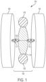
- FIG. 1 illustrates system components of a reconfigurable polar molecule 100 according to an embodiment.
- the primary rotating element 140 of the reconfigurable polar molecule 100 includes an elongated segment 110 having a first charged end 102 and a second charged end 103.
- Elongated segment 110 is substantially rigid, symmetric, and nonpolar.
- the elongated segment 110 provides a rigid scaffold that does not bend or twist.
- the elongated segment 110 has an elongated shape, or an elliptical shape, in some embodiments.
- the elongated segment 110 is defined by a long longitudinal axis and a shorter lateral axis.
- First charged end 102 and second charged end 103 are each arranged on the longitudinal axis of elongated segment 110. First charged end 102 and second charged end 103 are arranged on opposing ends of elongated segment 110 and form a permanent dipole through the longitudinal axis. First charged end 102 is a permanent positive ionic charge, or cation. Second charged end 103 is a permanent negative ionic charge, or an anion. First charged end 102 and second charged end 103 are not induced dipoles. First charged end 102 and second charged end 103 are permanent ionic charges. First charged end 102 and second charged end 103 are permanent ionic charges that are opposite charges.
- first charged end 102 is a permanent positive charge, or cation
- second charged end 103 is a permanent negative charge, or anion.
- first charged end 102 is a permanent negative charge
- second charged end 103 is a permanent positive charge.
- first charged end 102 and second charged end 103 are shown as being arranged on distal ends of elongated segment 110, first charged end 102 and second charged end 103 do not have to be specifically positioned on the far distal ends of elongated segment 110.
- the ionic charge of the first charged end 102 and second charged end 103 may be formed from a group that includes other atoms or groups such that the other atoms or groups are arranged on the distal ends.
- the rigid scaffold of elongated segment 110 ensure that first charged end 102 and second charged end 103 do not collapse onto one another.
- Elongated segment 110 has an elliptical shape.
- Elongated segment 110 may include hydrocarbon systems with aromatic rings, planar fused rings, and/or planar heterocyclic molecules. Suitable hydrocarbon systems may include one or more aromatic rings (polyaromatic ring structures), one or more conjugated ring structures, one or more substituted aromatic rings, one or more saturated hydrocarbons, one or more unsaturated hydrocarbons, one or more substituted hydrocarbons, or any combination thereof.
- Elongated segment 110 may include substitutions on the hydrocarbon systems, provided that the substitutions result in a nonpolar molecule.
- Elongated segment 110 is an anthracene derivative.
- Elongated segment 110 may include other nanoparticles, including, but not limited to, helices, carbon nanotubes, or combinations thereof. However, regardless of the composition, elongated segment 110 should remain substantially symmetric and nonpolar so that, as discussed below, primary rotating segment 140 may freely rotate.
- Elongated segment 110 is derivatized at each end on the longitudinal axis to form first charged end 102 and second charged end 103.
- First charged end 102 and second charged end 103 may include any positively charged ionic group or any negatively charged ionic group.
- positively charged ionic groups include positively charged amine groups, ammonium groups, phosphonium groups, sulfonium group, salts thereof, or any combination thereof.
- Non-limiting examples of negatively charged ionic groups include carboxylate groups, phosphate groups, phosphonate groups, sulfate groups, sulfonates groups, nitrate groups, nitrite groups, tosylate groups, brosylate groups, mesylate groups, selenate groups, salts thereof, or any combination thereof.
- Elongated segment 110 is connected to a first support 190 by a first bridging group 111.
- Elongated segment 110 is connected to a second support 191 by a second bridging group 112.
- First bridging group 111 and second bridging group 112 are each connected to first support 190 and second support 191, respectively, by one or more interactions or bonds.
- First bridging group 111 and second bridging group 112 are arranged at opposing sides of elongated segment 110 on the shorter lateral axis of elongated segment 110 and along the axis of rotation 120.
- First bridging group 111 and second bridging group 112 are also arranged substantially perpendicular to the permanent dipole formed on the longitudinal axis of elongated segment 110. As described below, first bridging group 111 and second bridging group 112 allow free rotation of elongated segment 110 with respect to first support 104 and second support 105, respectively.
- first bridging group 111 and first support 190 and second bridging group 112 and second support 191 depend on the identities of the constituent groups.
- the interactions and/or bonds between first bridging group 111 and first support 1190 and second bridging group 112 and second support 191 include, for example, covalent bonds, hydrogen bonds, electrostatic interactions, hydrophobic interactions, metal complexation interactions, or any combination thereof.
- First bridging group 111 and second bridging group 112 may be linear, nonpolar hydrocarbon groups. First bridging group 111 and second bridging group 112 may be the same or different. First bridging group 111 and second bridging group 112 anchor elongated segment 110 on axis of rotation 120 and provide a low barrier to free rotation (described below in FIG. 2 ). The axis of rotation 120 extends through the center of mass of primary rotating element 140. Each of first bridging group 111 and second bridging group 112 may be, for example, a linear hydrocarbon group, such as an alkynyl group, or an alkynyl-containing group.
- first bridging group 111 and second bridging group are each linear ethynyl groups or linear cyano groups.
- First bridging group 111 and second bridging group 112 may form carbon-carbon covalent bonds with first support 190 and second support 191, respectively.
- Elongated segment 110 can freely rotate under the influence of an external stimulus of appropriate magnitude and orientation, as described in further detail below with reference to FIG. 2 .
- elongated segment 110 rotates along the axis of rotation 120.
- the permanent dipole of elongated segment 110 is directed approximately perpendicular to first bridging group 111 and approximately perpendicular to second bridging group 112.
- First support 190 and second support 191 form attachment points for the primary rotating element 140.
- First support 190 and second support 191 are any nonpolar support structures or moieties.
- First support 190 and second support 191 each have mounting regions (first mounting region and second mounting region, respectively) upon which the first bridging group 111 and second bridging group 112 will bond, for example, via a covalent bond and/or other interaction or bonds.
- the rotatable molecule with be anchored between the first mounting region and the second mounting region, with the internal rotational axis extending there between.
- the first support 190 and second support 191 are mirror images of one another.
- First support 190 and second support 191 should provide an unobstructed path for rotation about the axis of rotation 120.
- First support 190 and second support 191 thus provide the material housing (packaging) around the rotational path (axis of rotation 120) of primary rotating element 140, which allows for full rotation in response to applied electric fields.
- the material housing forming first support 190 and second support 191 may be the same or different.
- the material housing forming first support 191 and second support 191 insulates primary rotating element 140 from dispersion and ambient vibrational modes.
- the packaging protects the primary rotating element 140 and prevents other molecules from interacting with or diffusing the spinning dipole.
- the shape and chemical make-up of the packaging forming first support 190 and second support 191 governs three-dimensional (3D) assembly into solid state 3D materials.
- the materials and composition of the first support 190 and second support 191 comprise pillared clays.
- the first support 190 and second support 191 provide insulating walls that are optimized for symmetric, three-dimensional assembly. First support 190 and second support 191 are thus symmetric. First support 190 and second support 191 are each also optimized for temperature stability, rotational axis stability, and electro-optic (EO) properties for the
- solid state reconfigurable polar molecule 100 has the following structure (structure II): wherein R 1 and R 2 are each independently a C 2 -C 4 alkyl group, a C 2 -C 4 alkenyl group, a C 2 -C 4 alkynyl group, a cyano group, or any combination thereof; R 3 is a positively charged ionic group; R 4 is a negatively charged ionic group; and R 5 and R 6 are each independently a non-polar support moiety.
- the C 2 -C 4 alkyl group, C 2 -C 4 alkenyl group, and C 2 -C 4 alkynyl group may be branched, unbranched, substituted, or unsubstituted.
- solid state reconfigurable polar molecule 100 has the following structure (structure III): wherein R 1 and R 2 are each independently a single bond, a C 2 -C 4 alkyl group, a C 2 -C 4 alkenyl group, a C 2 -C 4 alkynyl group, a cyano group, or any combination thereof; R 3 is a positively charged ionic group; R 4 is a negatively charged ionic group; and R 5 and R 6 are each independently an non-polar support moiety.
- the C 2 -C 4 alkyl group, C 2 -C 4 alkenyl group, and C 2 -C 4 alkynyl group may be branched, unbranched, substituted, or unsubstituted.
- solid state reconfigurable polar molecule 100 includes an alkynyl group, as shown in structure III above, the axis of rotation 120 (shown in FIG. 1 ) extends through the alkynyl group and is arranged substantially perpendicular to the permanent dipole formed on elongated segment 110 from first charged end 102 and second charged end 103 on the long longitudinal axis.
- FIG. 2 illustrates the tunable electromagnetic response of the reconfigurable polar molecule 100.
- primary rotating element 140 lies in the x-y plane between first support 190 and second support 191, and the z-axis points into the page.
- the axis of rotation 120 is located along the x-axis.
- primary rotating element 140 Upon application of an external electric field 255, primary rotating element 140 rotates along its axis of rotation 120, away from the x-y plane and into the z-plane by a rotation angle ⁇ .
- the electric field 255 is shown as being applied in the y-axis direction, the electric field 255 may be applied in any direction(s).
- the magnitude of the applied electric field 255 determines the amount of rotation and the rotation angle ⁇ .
- the permanent dipole across the elongated segment 110 due to the first charged end 102 and second charged end 103 induces the rotation.
- primary rotating element 140 Because primary rotating element 140 is rigid, it remains anchored in first support 190 and second support 191 during rotation.
- first bridging group 111 and second bridging group 112 are linear groups, they allow free rotation towards the z-plane, which is arranged substantially perpendicular to the x-y plane.
- the primary rotating element 140 rotates through rotation angle ⁇ , a number of stable and unstable conformations may be possible. Some conformations may be more energetically favored than others.
- the stability of the conformations depends on the composition of the primary rotating element 140 and the surrounding packaging 304 (including first support 190 and second support 191). Upon application of the electric field 255, primary rotating element 140 rotates through rotation angle ⁇ to the lowest energy conformation.
- the above-described reconfigurable polar molecules are combined into a plurality and ordered or arranged in a lattice to form a solid state material.
- the solid state materials Compared to liquid crystalline materials, the solid state materials have improved thermal stability and therefore may be used in wider temperature ranges.
- the reconfigurable polar molecules and solid state materials made therefrom may be used at temperatures in a range from about a cryogenic temperature to about 400°C.
- the reconfigurable polar molecules described above also provide other advantages.
- the molecules can be used as a dopant for a host material. For example, if polar molecules are in a dielectric material, under certain conditions, they may be aligned and become radiators (antenna/dipoles). In another example, the polar molecule's adaptive orientation will impact the reflectivity/transmissivity of the material. Furthermore, using them as dopants in certain applications can decrease the energy gap in certain dielectrics.
- the polar molecules and materials may be used in RF and IR optical applications.
- the polar molecules and materials also can be applied in the fields of spintronic devices and logic gates and quantum optics. These polar molecules also can interact with incoming signals of various polarizations, functioning as a sensor. Further, the molecules and materials may be used as a polarization transformer. Because of their size, the molecules can be used to implement switching capability down to the nanometer scale.
- FIG. 3 illustrates a packaged solid state material 300 having unit cells 301 of reconfigurable polar molecules arranged in a lattice.
- Each of the unit cells 301 includes a primary rotating element that includes an elongated segment that includes a first charged end with a positive charge and a second charged end with a negative charge.
- the primary rotating element is a rigid molecule with a permanent dipole.
- the primary rotating element has an axis of rotation 320 that extends through its center of mass.
- the primary rotating element is anchored by bridging groups (first bridging group and second bridging group) (not shown in FIG. 3 for clarity) in a packaging 304 (including a first support and second support).
- the packaging 304 provides a housing around the rotational path of the primary rotating element to insulate from dispersion and ambient vibrational modes.
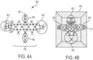
- FIG. 4A is a three-dimensional illustration of a primary rotating element 400 not according to the claimed solid state material of claim 1.
- the primary rotating element 400 is an ammonium phosphate ethynyl-anthracene derivative, which has the following chemical structure (structure IV): wherein R 1 is an ammonium group (-N(R) 3 + ), and R 2 is a phosphate group (PO 4 (R) 2 - ).
- An ethynyl-anthracene molecule forms elongated segment 430.
- the ethynl groups arranged on opposing sides of the central ring portion of the anthracene form the bridging groups 440 (first bridging group and second bridging group) that will anchor the primary rotating element 400 to the packaging 450, as shown in FIG. 4B .
- the axis of rotation 460 extends through the bridging groups 440.
- the ethynyl-anthracene molecule is derivatized with a positively charged ammonium group to form first charged end 402.
- the ethynyl-anthracene derivative is derivatized with a negatively charged phosphate group to form second charged end 403.
- the derivatives on the ethynyl-anthracene molecule portion may be optimized for specific applications.
- FIG. 4B is a primary rotating element 400 anchored within a packaging 450 architecture.
- the packaging 450 (or support) include polyaromatic walls, in some embodiments, that minimize dispersion during rotation of the primary rotating element 400.
- the ammonium group and the phosphate group provide a permanent dipole across the primary rotating element 400, which is oriented through an applied electric field.
- the ethynyl groups forming the bridging groups 440 that anchor the primary rotating element 400 on the axis of rotation 460 that provides a low barrier to rotation.
- FIG. 4B is shown for illustrative purposes only.
- the ethynyl groups of primary rotating element 430 are shown as being superimposed into packaging 450, the ethynyl groups will form covalent bonds (carbon-carbon bonds) with the molecule of the packaging 450.
- reaction scheme I the reaction scheme
- R 1 is an ammonium group
- R 2 is a phosphate group
- R 3 is a carbon-containing group of a first support
- R 4 is a carbon-containing group of a second support
- covalent carbon-carbon bonds are formed between the ethynyl groups and each of R 3 and R 4 .
- the reconfigurable polar molecules described in the above embodiments may be used in a variety of applications, for example, as sensors or molecular switches. When used as a switch, the molecules are switched between “on” and “off' states.
- the reconfigurable polar molecule may be placed between two electrodes so that an electric field with an appropriate magnitude and orientation, produced between the two electrodes, causes the primary rotating element to rotate.
- the orientation of the molecule located between the two electrodes can vary depending on the type of molecule selected and how the molecule is used.
- the molecules can interact with incoming signals (electric fields) of various polarizations combined with local voltages for control purposes. For instance, by controlling the rotational anisotropy of the polar molecule, the reflectivity of the surface can be controlled, and therefore, the RCS can be controlled.
- FIG. 5A is a three-dimensional illustration of an exemplary packaging architecture for primary rotating element 140 packaged within a support structure (first support 190 and second support 191), which is described above in FIG. 1 .
- the wall construction forming the packaging of second support 191 is a mixed-saturation polyaromatic system.
- Second support 191 includes two sets of ring structures 502, as well as two sets of alkyl groups 503, as shown in FIG. 5B , which is a side view of molecule shown in FIG. 5A .
- the groups 503 also can be cyclo-alkyl groups, with varying degrees of unsaturation.
- First support 190 and second support 191 insulate primary rotating element 140 and protect it from dispersive interactions.
- First support 190 and second support 191 also provide specific binding sites for the primary rotating element 140, or in particular, for the first bridging group 111 and second bridging group 112.
- First support 190 and second support 191 should each provide a binding site that will easily bond with first bridging group 111 and second bridging group 112. Because of the molecular and chemical nature of the molecules forming first support 190 and second support 191, the primary rotating element 140 is protected from interactions with the packaging.
- Each set of ring structures 502 includes broken conjugation.
- each set of ring structures includes both aromatic rings and nonaromatic rings (or saturated rings) (i.e., an aromatic ring is fused with a nonaromatic ring).
- the fused organic ring structure of the molecule forming second support 191 breaks the extended conjugation.
- the resulting limited conjugation improves optical transparency.
- Extended conjugation generally results in visible color or other optical properties.
- limited conjugation in contrast, does not impose additional optical properties to the primary polar molecular that it contains.
- the molecule is a low dielectric, nonpolar compound that is nonreactive with the primary rotating element 140.
- first support 190 may include the same molecule shown in the exemplary packaging architecture for second support 191.
- FIG. 5C is a space-filling view of the exemplary packaging architecture of FIGs. 5A and 5B .
- the second bridging group 112 formed from the ethynyl group is shown in the central region of the molecule, with the ring structures 502 and alkyl groups 503 extending away from the central second bridging group 112.
- the packaging architecture exhibits internal mirror symmetry and may be a meso compound in some embodiments.
- the first support 190 and second support 191 may include other molecules with both fused ring structures and/or alkyl groups.
- the alkyl groups may be branched and/or bulky groups. Including bulky groups along the rotational axis where the primary rotating element is mounted in the packaging reduces the reactivity of the primary rotating element with the packaging.
- the rotatable molecule should be non-reactive with the first support 190 and second support 191, other than the intended mounting regions on the molecules. In other words, molecules forming first support 190 and second support 191 should have one biding site for a bridging group of the primary rotating element, with other portions of the molecule being nonreactive.
- each of first support 190 and second support 191 has the following structure (structure V): wherein each ring structure is optionally substituted, and the first bridging group 111 or second bridging group 112 bonds at the asterisk (*) position.
- a first ethynyl group from primary rotating element covalently bonds to the asterisk (*) position of one molecule of structure V
- a second ethynyl group from primary rotating element covalently bonds to the asterisk (*) position of another molecule of structure V.
- FIG. 6 illustrates a reaction scheme for bonding the primary rotating element 640 in the packaging architecture.
- Primary rotating element 640 includes a first bridging group 611, and a second bridging group 612.
- First bridging group 611 and second bridging group 612 each include an ethyne group.
- Primary rotating element 640 covalently bonds to first support 690 via the ethyne group of first bridging group 611 and second support 691 via the ethyne group of second bridging group 612.
- the covalent bonds between the ethyne groups and first support 690 and second support 691 are carbon-carbon bonds. Although additional bonds and/or interactions may stabilize the molecule.
- packaging architectures may include other types of self-assembling structures.
- suitable structures include carbon nanotubes, graphene, metal oxide nanowires, porphyrins, cyclodestrins, and phtalocines.
- Pillared clays are two-dimensional microporous materials with a high surface area and permanent porosity. Pillared clays can be controllably hydrated to open clay layers and form "pillars" between the clay layers, which creates a high pore volume. Other molecules, such as lipids, can also be inserted between the clay layers to adjust the spacing. A pillared clay is used as the packaging material. Multiple layers of pillared clays may be used to create multiple rotational axes, as described below.
- FIGs. 7A and 7B illustrate packaging designs with multiple axes for three-dimensional rotational anisotropy.
- reconfigurable polar molecule 700 is arranged with two orthogonal rotational axes.
- Reconfigurable polar molecule 700 has an internal rotational axis.
- An additional orthogonal rotational axis 741 is provided.
- FIG. 7B illustrates a packaging scheme with two non-orthogonal rotational axes (internal rotational axis 740 and non-orthogonal rotational axis 751).
- the packaging scheme can provide any number of rotational axes, both orthogonal and non-orthogonal.
- the number and type of rotational axes depend on the type and number of packaging material layers.
- multiple, orthogonal and non-orthogonal degrees of freedom can be accomplished by coupling packaging at different scales such that one layer is contained within another layer.
- the second (outer layer) packaging can mount the first (inner layer) packaging on an orthogonal or non-orthogonal axis, for example, as shown in FIGs. 7A and 7B , respectively. Multiple layers of packaging thus set the orientation of the internal degree(s) of freedom.
- the above-described packaging schemes may be used in a variety of applications.
- the schemes allow implementation of controllable rotational anisotropy in areas, such as, Radar Cross Section (RCS) applications (e.g., polarimetric transformers), electronic devices (e.g., spintronics), optical devices ( e.g., switches), reconfigurable structures, cyber technology applications, and quantum cryptography/computing.
- RCS Radar Cross Section
Landscapes
- Engineering & Computer Science (AREA)
- Chemical & Material Sciences (AREA)
- Nanotechnology (AREA)
- Physics & Mathematics (AREA)
- Crystallography & Structural Chemistry (AREA)
- Power Engineering (AREA)
- Organic Chemistry (AREA)
- Spectroscopy & Molecular Physics (AREA)
- General Physics & Mathematics (AREA)
- Life Sciences & Earth Sciences (AREA)
- Materials Engineering (AREA)
- Condensed Matter Physics & Semiconductors (AREA)
- Molecular Biology (AREA)
- Health & Medical Sciences (AREA)
- Optics & Photonics (AREA)
- Microelectronics & Electronic Packaging (AREA)
- General Health & Medical Sciences (AREA)
- Composite Materials (AREA)
- Mathematical Physics (AREA)
- Theoretical Computer Science (AREA)
- Manufacturing & Machinery (AREA)
- Biophysics (AREA)
- Electrochromic Elements, Electrophoresis, Or Variable Reflection Or Absorption Elements (AREA)
Description
- The present invention relates to nanomaterials, and more specifically, to nanomaterials as support structures.
- Generally, nanomaterials are materials composed of nanoscale unit cells. The individual unit cells may have sizes, at least in one dimension, between 1 and 1,000 nanometers (nm), or between 1 and 100 nm.
- Nanomaterials may be natural or synthetic. Natural nanomaterials occur in nature. Biological systems can feature natural, functional nanomaterials, such as virus capsid walls and inorganic crystal growths. Examples of synthetic nanomaterials include, for example, graphene, carbon nanotubes, inorganic nanomaterials (e.g., quantum dots, nanowires and nanorods), and metal oxide nanowires. Other examples of nanoscale structures used in nanomaterials include porphyrins, cyclodextrins, and phtalocines.
- Materials with structure at the nanoscale often have unique optical, electronic, or mechanical properties. Nano-structural chemistry is used to prepare materials with predetermined shapes and topography. Primary applications of self-assembling nanostructures are focused on, for example, nanowires, components of molecular scale electronics, and dye sensitive solar cells.
-
US2008269486A1 discloses organic molecules that are reconfigurable under application of an external electric field;US6430511B1 discloses a molecular computer formed by establishing arrays of spaced-apart input and output pins on opposing sides of a containment, injecting moleware in solution into the containment and then allowing the moleware to bridge the input and output pins; andUS2008002333A1 discloses a charge storage cell comprising two electrodes spaced apart by a dielectric layer incorporating a molecular switch. - According to an embodiment, a solid state material according to
present claim 1 comprises a plurality of reconfigurable polar molecules according topresent claim 1. - Yet, according to another embodiment, a method of packaging a reconfigurable molecules according to the present claims in a lattice to form a solid state material, the method comprising: providing a support structure according to the present claims; and anchoring a rotatable molecule according to the present claims between the first support portion and the second support portion; wherein the support structure allows the rotatable molecule to rotate through the internal rotational axis upon application of an applied electric field.
- The subject matter which is regarded as the invention is particularly pointed out and distinctly claimed in the claims at the conclusion of the specification. The foregoing and other features, and advantages of the invention are apparent from the following detailed description taken in conjunction with the accompanying drawings in which:
-
FIGs. 1-7B illustrate exemplary packaging (support structures) for solid state materials according to embodiments, in which: -
FIG. 1 illustrates system components of a reconfigurable polar molecule; -
FIG. 2 illustrates the tunable electromagnetic (EM) response of a solid state reconfigurable polar molecule; -
FIG. 3 illustrates a packaged solid state material having individual molecules arranged in a lattice; -
FIG. 4A is a three-dimensional illustration of a primary rotating element of a reconfigurable polar molecule; -
FIG. 4B is a primary rotating element anchored within a packaging architecture; -
FIG. 5A is a three-dimensional illustration of an exemplary packaging architecture; -
FIG. 5B is a side view of the three-dimensional illustration ofFIG. 5A ; -
FIG. 5C is a space-filling view of the exemplary packaging architecture ofFIGs. 5A and5B ; -
FIG. 6 illustrates a reaction scheme for bonding the primary rotating element in the packaging architecture; -
FIG. 7A illustrates a packaging design with multiple axes for three-dimensional rotational anisotropy; and -
FIG. 7B illustrates a packaging design with multiple axes for three-dimensional rotational anisotropy. - Because of their polar nature and rotational anisotropy, solid state polar molecules (the subject of embodiments of the invention described herein) may be used in a variety of RF and IR applications, thermal applications, quantum computing, spintronics, etc. One advantage of solid state polar molecules is that they have a wider thermal operating range compared to liquid polar molecules. Solid state polar molecules also have faster response times compared to liquid polar molecules. Furthermore, polar liquid molecules may be more sensitive to EM fields under certain circumstances or condition. For example, if the EM field is sufficiently strong, then translation and/or diffusion can occur, instead of rotation. Under some circumstances, due to their liquid state, liquid polar molecules may also become inherently disordered (or lose their alignment). Another challenge of liquid polar molecule materials is that they may operate at a limited range of temperatures due to the the molecules' dispersive and vibrational interactions with the host environment.
- Accordingly, various embodiments described herein provide self-assembling building blocks that provide empty space as a solid matrix packaging for reconfigurable polar molecules. The solid matrix enables introduction of solid state primary materials that have internal degrees of freedom, while still maintaining insulation from a diffusive environment. Thus, the packaging structures preserve internal degrees of freedom for rotational motion, as well as govern assembly characteristics.
- In some embodiments, the packaging scheme insulates rotatable polar molecules from temperature effects and minimizes diffusive interactions with the primary rotating material, while simultaneously exhibiting the intended shape and geometric properties to control self-assembly into the intended spatial arrangement. The packaging allows control of the specific orientation axis of the internal degree of freedom with respect to the crystallographic unit cell parameters, or with respect to externally applied electric fields. Further, the packaging introduces an adaptive and controllable anisotropy into the basic crystallographic unit system, which provides advantages in a variety of applications.
- As used herein, the term "reconfigurable" when used in reference to a molecule means rotating in response to an applied external electric field.
- As used herein, the term "polar" when used in reference to a molecule means having a net dipole as a result of partial negative and positive charges due to asymmetrically arranged polar bonds.
- As used herein, the term "nonpolar" when used in reference to a molecule means having no net dipole due to equal sharing of electrons between two atoms of a diatomic molecule or symmetrical arrangement of polar bonds in a more complex molecule.
- Turning now to the Figures,
FIGs. 1-7B illustrate exemplary packaging (support structures) for solid state materials according to embodiments.FIG. 1 illustrates system components of a reconfigurablepolar molecule 100 according to an embodiment. The primary rotatingelement 140 of the reconfigurablepolar molecule 100 includes anelongated segment 110 having a firstcharged end 102 and a second chargedend 103.Elongated segment 110 is substantially rigid, symmetric, and nonpolar. Theelongated segment 110 provides a rigid scaffold that does not bend or twist. Theelongated segment 110 has an elongated shape, or an elliptical shape, in some embodiments. Theelongated segment 110 is defined by a long longitudinal axis and a shorter lateral axis. - First charged
end 102 and second chargedend 103 are each arranged on the longitudinal axis ofelongated segment 110. First chargedend 102 and second chargedend 103 are arranged on opposing ends ofelongated segment 110 and form a permanent dipole through the longitudinal axis. First chargedend 102 is a permanent positive ionic charge, or cation. Second chargedend 103 is a permanent negative ionic charge, or an anion. First chargedend 102 and second chargedend 103 are not induced dipoles. First chargedend 102 and second chargedend 103 are permanent ionic charges. First chargedend 102 and second chargedend 103 are permanent ionic charges that are opposite charges. In one example, first chargedend 102 is a permanent positive charge, or cation, and second chargedend 103 is a permanent negative charge, or anion. In another example, first chargedend 102 is a permanent negative charge, and second chargedend 103 is a permanent positive charge. - Although first charged
end 102 and second chargedend 103 are shown as being arranged on distal ends ofelongated segment 110, first chargedend 102 and second chargedend 103 do not have to be specifically positioned on the far distal ends ofelongated segment 110. In other words, the ionic charge of the first chargedend 102 and second chargedend 103 may be formed from a group that includes other atoms or groups such that the other atoms or groups are arranged on the distal ends. The rigid scaffold ofelongated segment 110 ensure that first chargedend 102 and second chargedend 103 do not collapse onto one another. - As mentioned above,
elongated segment 110 has an elliptical shape.Elongated segment 110 may include hydrocarbon systems with aromatic rings, planar fused rings, and/or planar heterocyclic molecules. Suitable hydrocarbon systems may include one or more aromatic rings (polyaromatic ring structures), one or more conjugated ring structures, one or more substituted aromatic rings, one or more saturated hydrocarbons, one or more unsaturated hydrocarbons, one or more substituted hydrocarbons, or any combination thereof.Elongated segment 110 may include substitutions on the hydrocarbon systems, provided that the substitutions result in a nonpolar molecule. -
Elongated segment 110 is an anthracene derivative. -
Elongated segment 110 may include other nanoparticles, including, but not limited to, helices, carbon nanotubes, or combinations thereof. However, regardless of the composition,elongated segment 110 should remain substantially symmetric and nonpolar so that, as discussed below, primary rotatingsegment 140 may freely rotate. -
Elongated segment 110 is derivatized at each end on the longitudinal axis to form first chargedend 102 and second chargedend 103. First chargedend 102 and second chargedend 103 may include any positively charged ionic group or any negatively charged ionic group. Non-limiting examples of positively charged ionic groups include positively charged amine groups, ammonium groups, phosphonium groups, sulfonium group, salts thereof, or any combination thereof. Non-limiting examples of negatively charged ionic groups include carboxylate groups, phosphate groups, phosphonate groups, sulfate groups, sulfonates groups, nitrate groups, nitrite groups, tosylate groups, brosylate groups, mesylate groups, selenate groups, salts thereof, or any combination thereof. -
Elongated segment 110 is connected to afirst support 190 by a first bridging group 111.Elongated segment 110 is connected to asecond support 191 by asecond bridging group 112. First bridging group 111 andsecond bridging group 112 are each connected tofirst support 190 andsecond support 191, respectively, by one or more interactions or bonds. First bridging group 111 andsecond bridging group 112 are arranged at opposing sides ofelongated segment 110 on the shorter lateral axis ofelongated segment 110 and along the axis ofrotation 120. First bridging group 111 andsecond bridging group 112 are also arranged substantially perpendicular to the permanent dipole formed on the longitudinal axis ofelongated segment 110. As described below, first bridging group 111 andsecond bridging group 112 allow free rotation ofelongated segment 110 with respect to first support 104 and second support 105, respectively. - The interactions and/or bonds between first bridging group 111 and
first support 190 andsecond bridging group 112 andsecond support 191 depend on the identities of the constituent groups. The interactions and/or bonds between first bridging group 111 and first support 1190 andsecond bridging group 112 andsecond support 191 include, for example, covalent bonds, hydrogen bonds, electrostatic interactions, hydrophobic interactions, metal complexation interactions, or any combination thereof. - First bridging group 111 and
second bridging group 112 may be linear, nonpolar hydrocarbon groups. First bridging group 111 andsecond bridging group 112 may be the same or different. First bridging group 111 andsecond bridging group 112 anchor elongatedsegment 110 on axis ofrotation 120 and provide a low barrier to free rotation (described below inFIG. 2 ). The axis ofrotation 120 extends through the center of mass of primaryrotating element 140. Each of first bridging group 111 andsecond bridging group 112 may be, for example, a linear hydrocarbon group, such as an alkynyl group, or an alkynyl-containing group. In one example, first bridging group 111 and second bridging group are each linear ethynyl groups or linear cyano groups. First bridging group 111 andsecond bridging group 112 may form carbon-carbon covalent bonds withfirst support 190 andsecond support 191, respectively. -
Elongated segment 110 can freely rotate under the influence of an external stimulus of appropriate magnitude and orientation, as described in further detail below with reference toFIG. 2 . For example, under the influence of an externally applied electric field,elongated segment 110 rotates along the axis ofrotation 120. The permanent dipole ofelongated segment 110 is directed approximately perpendicular to first bridging group 111 and approximately perpendicular tosecond bridging group 112. -
First support 190 andsecond support 191 form attachment points for the primaryrotating element 140.First support 190 andsecond support 191 are any nonpolar support structures or moieties.First support 190 andsecond support 191 each have mounting regions (first mounting region and second mounting region, respectively) upon which the first bridging group 111 andsecond bridging group 112 will bond, for example, via a covalent bond and/or other interaction or bonds. As a result, the rotatable molecule with be anchored between the first mounting region and the second mounting region, with the internal rotational axis extending there between. In the invention, thefirst support 190 andsecond support 191 are mirror images of one another. -
First support 190 andsecond support 191 should provide an unobstructed path for rotation about the axis ofrotation 120.First support 190 andsecond support 191 thus provide the material housing (packaging) around the rotational path (axis of rotation 120) of primaryrotating element 140, which allows for full rotation in response to applied electric fields. The material housing formingfirst support 190 andsecond support 191 may be the same or different. The material housing formingfirst support 191 andsecond support 191 insulates primaryrotating element 140 from dispersion and ambient vibrational modes. The packaging protects the primaryrotating element 140 and prevents other molecules from interacting with or diffusing the spinning dipole. The shape and chemical make-up of the packaging formingfirst support 190 andsecond support 191 governs three-dimensional (3D) assembly into solid state 3D materials. - The materials and composition of the
first support 190 andsecond support 191 comprise pillared clays. - The
first support 190 andsecond support 191 provide insulating walls that are optimized for symmetric, three-dimensional assembly.First support 190 andsecond support 191 are thus symmetric.First support 190 andsecond support 191 are each also optimized for temperature stability, rotational axis stability, and electro-optic (EO) properties for the - In the invention, solid state reconfigurable
polar molecule 100 has the following structure (structure II):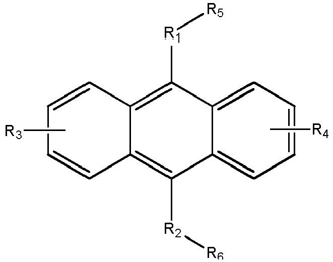
- In another embodiment not falling under the solid state material as defined in
claim 1, solid state reconfigurablepolar molecule 100 has the following structure (structure III):
- When solid state reconfigurable
polar molecule 100 includes an alkynyl group, as shown in structure III above, the axis of rotation 120 (shown inFIG. 1 ) extends through the alkynyl group and is arranged substantially perpendicular to the permanent dipole formed onelongated segment 110 from first chargedend 102 and second chargedend 103 on the long longitudinal axis. -
FIG. 2 illustrates the tunable electromagnetic response of the reconfigurablepolar molecule 100. In the coordinate system shown, primaryrotating element 140 lies in the x-y plane betweenfirst support 190 andsecond support 191, and the z-axis points into the page. The axis ofrotation 120 is located along the x-axis. - Upon application of an external
electric field 255, primaryrotating element 140 rotates along its axis ofrotation 120, away from the x-y plane and into the z-plane by a rotation angle θ. Although theelectric field 255 is shown as being applied in the y-axis direction, theelectric field 255 may be applied in any direction(s). The magnitude of the appliedelectric field 255 determines the amount of rotation and the rotation angle θ. The permanent dipole across theelongated segment 110 due to the first chargedend 102 and second chargedend 103 induces the rotation. Because primaryrotating element 140 is rigid, it remains anchored infirst support 190 andsecond support 191 during rotation. Also because first bridging group 111 andsecond bridging group 112 are linear groups, they allow free rotation towards the z-plane, which is arranged substantially perpendicular to the x-y plane. - As the primary
rotating element 140 rotates through rotation angle θ, a number of stable and unstable conformations may be possible. Some conformations may be more energetically favored than others. The stability of the conformations depends on the composition of the primaryrotating element 140 and the surrounding packaging 304 (includingfirst support 190 and second support 191). Upon application of theelectric field 255, primaryrotating element 140 rotates through rotation angle θ to the lowest energy conformation. - The above-described reconfigurable polar molecules are combined into a plurality and ordered or arranged in a lattice to form a solid state material. Compared to liquid crystalline materials, the solid state materials have improved thermal stability and therefore may be used in wider temperature ranges. For example, the reconfigurable polar molecules and solid state materials made therefrom may be used at temperatures in a range from about a cryogenic temperature to about 400°C.
- The reconfigurable polar molecules described above also provide other advantages. The molecules can be used as a dopant for a host material. For example, if polar molecules are in a dielectric material, under certain conditions, they may be aligned and become radiators (antenna/dipoles). In another example, the polar molecule's adaptive orientation will impact the reflectivity/transmissivity of the material. Furthermore, using them as dopants in certain applications can decrease the energy gap in certain dielectrics.
- The polar molecules and materials may be used in RF and IR optical applications. The polar molecules and materials also can be applied in the fields of spintronic devices and logic gates and quantum optics. These polar molecules also can interact with incoming signals of various polarizations, functioning as a sensor. Further, the molecules and materials may be used as a polarization transformer. Because of their size, the molecules can be used to implement switching capability down to the nanometer scale.
- In an exemplary embodiment,
FIG. 3 illustrates a packagedsolid state material 300 havingunit cells 301 of reconfigurable polar molecules arranged in a lattice. Each of theunit cells 301 includes a primary rotating element that includes an elongated segment that includes a first charged end with a positive charge and a second charged end with a negative charge. The primary rotating element is a rigid molecule with a permanent dipole. The primary rotating element has an axis ofrotation 320 that extends through its center of mass. The primary rotating element is anchored by bridging groups (first bridging group and second bridging group) (not shown inFIG. 3 for clarity) in a packaging 304 (including a first support and second support). The packaging 304 provides a housing around the rotational path of the primary rotating element to insulate from dispersion and ambient vibrational modes. -
FIG. 4A is a three-dimensional illustration of a primaryrotating element 400 not according to the claimed solid state material ofclaim 1. The primaryrotating element 400 is an ammonium phosphate ethynyl-anthracene derivative, which has the following chemical structure (structure IV):
- An ethynyl-anthracene molecule forms elongated
segment 430. The ethynl groups arranged on opposing sides of the central ring portion of the anthracene form the bridging groups 440 (first bridging group and second bridging group) that will anchor the primaryrotating element 400 to thepackaging 450, as shown inFIG. 4B . The axis ofrotation 460 extends through the bridging groups 440. - The ethynyl-anthracene molecule is derivatized with a positively charged ammonium group to form first charged
end 402. The ethynyl-anthracene derivative is derivatized with a negatively charged phosphate group to form second chargedend 403. However, the derivatives on the ethynyl-anthracene molecule portion may be optimized for specific applications. -
FIG. 4B is a primaryrotating element 400 anchored within apackaging 450 architecture. The packaging 450 (or support) include polyaromatic walls, in some embodiments, that minimize dispersion during rotation of the primaryrotating element 400. The ammonium group and the phosphate group provide a permanent dipole across the primaryrotating element 400, which is oriented through an applied electric field. The ethynyl groups forming the bridginggroups 440 that anchor the primaryrotating element 400 on the axis ofrotation 460 that provides a low barrier to rotation. - It is noted that
FIG. 4B is shown for illustrative purposes only. Although the ethynyl groups of primaryrotating element 430 are shown as being superimposed intopackaging 450, the ethynyl groups will form covalent bonds (carbon-carbon bonds) with the molecule of thepackaging 450. For example, the reaction between the primaryrotating element 400 andpackaging 450 is illustrated by the following reaction scheme (reaction scheme I), whereby it is noted that the compounds are not according to the claimed solid state material ofclaim 1.
- The reconfigurable polar molecules described in the above embodiments may be used in a variety of applications, for example, as sensors or molecular switches. When used as a switch, the molecules are switched between "on" and "off' states. The reconfigurable polar molecule may be placed between two electrodes so that an electric field with an appropriate magnitude and orientation, produced between the two electrodes, causes the primary rotating element to rotate. The orientation of the molecule located between the two electrodes can vary depending on the type of molecule selected and how the molecule is used.
- When the reconfigurable polar molecules, and solid state materials made therefrom, are used as a sensor, the molecules can interact with incoming signals (electric fields) of various polarizations combined with local voltages for control purposes. For instance, by controlling the rotational anisotropy of the polar molecule, the reflectivity of the surface can be controlled, and therefore, the RCS can be controlled.
-
FIG. 5A is a three-dimensional illustration of an exemplary packaging architecture for primaryrotating element 140 packaged within a support structure (first support 190 and second support 191), which is described above inFIG. 1 . The wall construction forming the packaging ofsecond support 191 is a mixed-saturation polyaromatic system. -
Second support 191 includes two sets ofring structures 502, as well as two sets ofalkyl groups 503, as shown inFIG. 5B , which is a side view of molecule shown inFIG. 5A . Thegroups 503 also can be cyclo-alkyl groups, with varying degrees of unsaturation. -
First support 190 andsecond support 191 insulate primaryrotating element 140 and protect it from dispersive interactions.First support 190 andsecond support 191 also provide specific binding sites for the primaryrotating element 140, or in particular, for the first bridging group 111 andsecond bridging group 112.First support 190 andsecond support 191 should each provide a binding site that will easily bond with first bridging group 111 andsecond bridging group 112. Because of the molecular and chemical nature of the molecules formingfirst support 190 andsecond support 191, the primaryrotating element 140 is protected from interactions with the packaging. - Each set of
ring structures 502 includes broken conjugation. In other words, each set of ring structures includes both aromatic rings and nonaromatic rings (or saturated rings) (i.e., an aromatic ring is fused with a nonaromatic ring). The fused organic ring structure of the molecule formingsecond support 191 breaks the extended conjugation. The resulting limited conjugation improves optical transparency. Extended conjugation generally results in visible color or other optical properties. However, limited conjugation, in contrast, does not impose additional optical properties to the primary polar molecular that it contains. As shown, the molecule is a low dielectric, nonpolar compound that is nonreactive with the primaryrotating element 140. Although not shown,first support 190 may include the same molecule shown in the exemplary packaging architecture forsecond support 191. -
FIG. 5C is a space-filling view of the exemplary packaging architecture ofFIGs. 5A and5B . Thesecond bridging group 112 formed from the ethynyl group is shown in the central region of the molecule, with thering structures 502 andalkyl groups 503 extending away from the centralsecond bridging group 112. As shown, the packaging architecture exhibits internal mirror symmetry and may be a meso compound in some embodiments. - In addition to the structure shown in
FIGs. 5A-5C , thefirst support 190 andsecond support 191 may include other molecules with both fused ring structures and/or alkyl groups. The alkyl groups may be branched and/or bulky groups. Including bulky groups along the rotational axis where the primary rotating element is mounted in the packaging reduces the reactivity of the primary rotating element with the packaging. To promote self-assembly, the rotatable molecule should be non-reactive with thefirst support 190 andsecond support 191, other than the intended mounting regions on the molecules. In other words, molecules formingfirst support 190 andsecond support 191 should have one biding site for a bridging group of the primary rotating element, with other portions of the molecule being nonreactive. - In a non-inventive exemplary embodiment, each of
first support 190 andsecond support 191 has the following structure (structure V):
second bridging group 112 bonds at the asterisk (*) position. - In one example, a first ethynyl group from primary rotating element covalently bonds to the asterisk (*) position of one molecule of structure V, and a second ethynyl group from primary rotating element covalently bonds to the asterisk (*) position of another molecule of structure V.
-
FIG. 6 illustrates a reaction scheme for bonding the primaryrotating element 640 in the packaging architecture. Primaryrotating element 640 includes afirst bridging group 611, and asecond bridging group 612.First bridging group 611 andsecond bridging group 612 each include an ethyne group. Primaryrotating element 640 covalently bonds tofirst support 690 via the ethyne group offirst bridging group 611 andsecond support 691 via the ethyne group ofsecond bridging group 612. The covalent bonds between the ethyne groups andfirst support 690 andsecond support 691 are carbon-carbon bonds. Although additional bonds and/or interactions may stabilize the molecule. - In addition to the above-described molecules and structures, the packaging architectures may include other types of self-assembling structures. Examples of suitable structures include carbon nanotubes, graphene, metal oxide nanowires, porphyrins, cyclodestrins, and phtalocines.
- Pillared clays are two-dimensional microporous materials with a high surface area and permanent porosity. Pillared clays can be controllably hydrated to open clay layers and form "pillars" between the clay layers, which creates a high pore volume. Other molecules, such as lipids, can also be inserted between the clay layers to adjust the spacing. A pillared clay is used as the packaging material. Multiple layers of pillared clays may be used to create multiple rotational axes, as described below.
-
FIGs. 7A and 7B illustrate packaging designs with multiple axes for three-dimensional rotational anisotropy. InFIG. 7A , reconfigurablepolar molecule 700 is arranged with two orthogonal rotational axes. Reconfigurablepolar molecule 700 has an internal rotational axis. An additional orthogonalrotational axis 741 is provided.FIG. 7B illustrates a packaging scheme with two non-orthogonal rotational axes (internalrotational axis 740 and non-orthogonal rotational axis 751). - Although two rotational axes are illustrated in
FIGs. 7A and 7B , the packaging scheme can provide any number of rotational axes, both orthogonal and non-orthogonal. The number and type of rotational axes depend on the type and number of packaging material layers. For example, multiple, orthogonal and non-orthogonal degrees of freedom can be accomplished by coupling packaging at different scales such that one layer is contained within another layer. The second (outer layer) packaging can mount the first (inner layer) packaging on an orthogonal or non-orthogonal axis, for example, as shown inFIGs. 7A and 7B , respectively. Multiple layers of packaging thus set the orientation of the internal degree(s) of freedom. - The above-described packaging schemes may be used in a variety of applications. The schemes allow implementation of controllable rotational anisotropy in areas, such as, Radar Cross Section (RCS) applications (e.g., polarimetric transformers), electronic devices (e.g., spintronics), optical devices (e.g., switches), reconfigurable structures, cyber technology applications, and quantum cryptography/computing.
Claims (5)
- A solid state material (300) comprising a plurality of reconfigurable polar molecules (100), wherein each of the reconfigurable polar molecules has the following structure:
 wherein R1 and R2 are each independently a C2-C4 alkyl group, a C2-C4 alkenyl group, a C2-C4 alkynyl group, a cyano group, or any combination thereof; R3 is a positively charged ionic group; R4 is a negatively charged ionic group; and R5 is a first non-polar support portion (190, 690) and R6 is a second non-polar support portion (191, 691);wherein the first support portion (190, 690) and the second support portion (191, 691) comprise pillared clays; andwherein the first support portion (190, 690) and the second support portion (191, 691) are mirror images of one another; andwherein the plurality of the reconfigurable polar molecules are ordered in a lattice.
 - The solid state material (300) of claim 1, wherein each of the first non-polar support portion (190, 690) and the second non-polar support portion (191, 691) is a meso compound.
- A method of packaging reconfigurable polar molecules (100) in a lattice to form a solid state material (300), the method comprising:providing a support structure comprising a first support portion (190, 690) having a first mounting region and a second support portion (191, 691) having a second mounting region, the first support portion (190, 690) and the second support portion (191, 691) being mirror images of one another and wherein the first support portion (190, 690) and the second support portion (191, 691) comprise pillared clays; andanchoring a rotatable molecule between the first support portion (190, 690) and the second support portion (191, 691) on the first mounting region and the second mounting region, the rotatable molecule having an internal rotational axis (120, 320, 460) extending from the first mounting region to the second mounting region;wherein the rotatable molecules comprise a permanent dipole that extends substantially perpendicular to the internal rotational axis (120, 320, 460); andwherein the support structure allows the rotatable molecule to rotate through the internal rotational axis upon application of an applied electric field (255).
- The method of claim 3, wherein the rotatable molecules are initially arranged in an x-y plane, and applying the electric field (255) induces the rotatable molecules to rotate away from the x-y plane and towards a z-plane that is arranged perpendicular to the x-y plane.
- The method of claim 3, wherein the first support portion (190, 690) and the second support portion (191, 691) each comprise a saturated ring structure and an aromatic ring structure, optionally wherein the first support portion and the second support portion each further comprise alkyl groups (503).
Applications Claiming Priority (2)
| Application Number | Priority Date | Filing Date | Title |
|---|---|---|---|
| US15/425,141 US10421701B2 (en) | 2017-02-06 | 2017-02-06 | Method for material packaging and developing rotationally anisotropic materials |
| PCT/US2018/016612 WO2018144835A1 (en) | 2017-02-06 | 2018-02-02 | Method for material packaging and developing rotationally anisotropic materials |
Publications (2)
| Publication Number | Publication Date |
|---|---|
| EP3577702A1 EP3577702A1 (en) | 2019-12-11 |
| EP3577702B1 true EP3577702B1 (en) | 2024-03-27 |
Family
ID=61581747
Family Applications (1)
| Application Number | Title | Priority Date | Filing Date |
|---|---|---|---|
| EP18709440.4A Active EP3577702B1 (en) | 2017-02-06 | 2018-02-02 | Method for material packaging and developing rotationally anisotropic materials |
Country Status (3)
| Country | Link |
|---|---|
| US (1) | US10421701B2 (en) |
| EP (1) | EP3577702B1 (en) |
| WO (1) | WO2018144835A1 (en) |
Families Citing this family (1)
| Publication number | Priority date | Publication date | Assignee | Title |
|---|---|---|---|---|
| US10703692B2 (en) * | 2017-02-06 | 2020-07-07 | Raytheon Company | Solid state materials with tunable dielectric response and rotational anisotropy |
Family Cites Families (9)
| Publication number | Priority date | Publication date | Assignee | Title |
|---|---|---|---|---|
| US3911038A (en) | 1974-03-25 | 1975-10-07 | American Cyanamid Co | Process for making bis(phenylethylnyl)anthracenes |
| US4547317A (en) | 1982-10-25 | 1985-10-15 | American Cyanamid Company | Poly(ethyleneoxy)-substituted-9,10-bis(phenylethynyl)anthracene mixtures |
| JP2003530610A (en) * | 1999-01-21 | 2003-10-14 | サウス カロライナ大学 | Molecular computer |
| US6628016B2 (en) * | 2000-03-20 | 2003-09-30 | California Molecular Electronics Corporation | Molecular dipolar rotors |
| US8455047B2 (en) * | 2006-04-28 | 2013-06-04 | Applied Nanotech Holdings, Inc. | Method for growing carbon nanotubes on clay platelets |
| US7580239B2 (en) * | 2006-06-29 | 2009-08-25 | Hewlett-Packard Development Company, L.P. | Capacitive latched bi-stable molecular switch |
| US20090286065A1 (en) * | 2006-07-14 | 2009-11-19 | Paul Scherrer Institut | Method for generating supramolecular rotary devices and supramolecular rotary switch |
| US8044212B2 (en) * | 2007-04-30 | 2011-10-25 | Hewlett-Packard Development Company, L.P. | Reconfigurable molecules and molecular switches, sensors, and dyes employing the same |
| KR101427588B1 (en) * | 2007-06-14 | 2014-08-08 | 삼성디스플레이 주식회사 | Liquid crystal composition and liquid crystlal display device having the same |
-
2017
- 2017-02-06 US US15/425,141 patent/US10421701B2/en active Active
-
2018
- 2018-02-02 WO PCT/US2018/016612 patent/WO2018144835A1/en not_active Ceased
- 2018-02-02 EP EP18709440.4A patent/EP3577702B1/en active Active
Also Published As
| Publication number | Publication date |
|---|---|
| US10421701B2 (en) | 2019-09-24 |
| WO2018144835A1 (en) | 2018-08-09 |
| US20180222825A1 (en) | 2018-08-09 |
| EP3577702A1 (en) | 2019-12-11 |
Similar Documents
| Publication | Publication Date | Title |
|---|---|---|
| Correia et al. | Low-field giant magneto-ionic response in polymer-based nanocomposites | |
| Li et al. | CrXTe 3 (X= Si, Ge) nanosheets: two dimensional intrinsic ferromagnetic semiconductors | |
| Hyun et al. | Rheology of poly (ethylene oxide)/organoclay nanocomposites | |
| Li et al. | Strain controlled ferromagnetic-antiferromagnetic transformation in Mn-doped silicene for information transformation devices | |
| Kuijk et al. | Effect of external electric fields on the phase behavior of colloidal silica rods | |
| Paul et al. | Ferroelectric phase transitions in ultrathin films of BaTiO 3 | |
| Guo et al. | Theoretical understanding of polar topological phase transitions in functional oxide heterostructures: A review | |
| Li et al. | Programmable ultralight magnets via orientational arrangement of ferromagnetic nanoparticles within aerogel hosts | |
| Zhang et al. | Distorted monolayer ReS2 with low-magnetic-field controlled magnetoelectricity | |
| Patla et al. | Ion specificity towards structure-property correlation of poly (ethylene oxide)[PEO]-NH4I and PEO-KBr composite solid polymer electrolyte | |
| US10421701B2 (en) | Method for material packaging and developing rotationally anisotropic materials | |
| Qiao et al. | Polarization evolution in nanometer-thick PbZrO3 films: Implications for energy storage and pyroelectric sensors | |
| Liang et al. | Dielectric properties of silver nanowires-filled polyvinylidene fluoride composite with low percolation threshold | |
| JP2013152875A (en) | High-conductive ionic liquid composition | |
| Huang et al. | Broadband microwave absorption and adaptable multifunctionality of carbonaceous chiral metamaterials under deep subwavelength thickness | |
| US20120112167A1 (en) | Nanoscale electronic device | |
| Dang et al. | Polar toron structure in ferroelectric core-shell nanoparticles | |
| Khikhlovskyi et al. | The renaissance of multiferroics: bismuth ferrite (BiFeO3)–a candidate multiferroic material in nanoscience | |
| US10703692B2 (en) | Solid state materials with tunable dielectric response and rotational anisotropy | |
| Hernández et al. | How water makes graphene metallic | |
| Nakato et al. | Liquid-Crystalline Photonic Sandwich: Electroresponsive Colloids of Clay Nanosheets Loading Photofunctional Dyes | |
| Lich et al. | Theoretical studies on controlling the chirality of helical polarization vortices in ferroelectric nanowires: Implications for reconfigurable electronic devices | |
| Ren | Nanodots of multiferroic oxide material BiFeO3 from the first principles | |
| Halcrow et al. | Ferroelectric domain wall clusters in perfectly screened barium titanate type systems | |
| EP4160707A1 (en) | Thermal and electromagnetic generation and switching of chirality in ferroelectrics |
Legal Events
| Date | Code | Title | Description |
|---|---|---|---|
| STAA | Information on the status of an ep patent application or granted ep patent |
Free format text: STATUS: UNKNOWN |
|
| STAA | Information on the status of an ep patent application or granted ep patent |
Free format text: STATUS: THE INTERNATIONAL PUBLICATION HAS BEEN MADE |
|
| PUAI | Public reference made under article 153(3) epc to a published international application that has entered the european phase |
Free format text: ORIGINAL CODE: 0009012 |
|
| STAA | Information on the status of an ep patent application or granted ep patent |
Free format text: STATUS: REQUEST FOR EXAMINATION WAS MADE |
|
| 17P | Request for examination filed |
Effective date: 20190805 |
|
| AK | Designated contracting states |
Kind code of ref document: A1 Designated state(s): AL AT BE BG CH CY CZ DE DK EE ES FI FR GB GR HR HU IE IS IT LI LT LU LV MC MK MT NL NO PL PT RO RS SE SI SK SM TR |
|
| AX | Request for extension of the european patent |
Extension state: BA ME |
|
| DAV | Request for validation of the european patent (deleted) | ||
| DAX | Request for extension of the european patent (deleted) | ||
| STAA | Information on the status of an ep patent application or granted ep patent |
Free format text: STATUS: EXAMINATION IS IN PROGRESS |
|
| 17Q | First examination report despatched |
Effective date: 20200810 |
|
| GRAP | Despatch of communication of intention to grant a patent |
Free format text: ORIGINAL CODE: EPIDOSNIGR1 |
|
| STAA | Information on the status of an ep patent application or granted ep patent |
Free format text: STATUS: GRANT OF PATENT IS INTENDED |
|
| INTG | Intention to grant announced |
Effective date: 20220311 |
|
| GRAJ | Information related to disapproval of communication of intention to grant by the applicant or resumption of examination proceedings by the epo deleted |
Free format text: ORIGINAL CODE: EPIDOSDIGR1 |
|
| STAA | Information on the status of an ep patent application or granted ep patent |
Free format text: STATUS: EXAMINATION IS IN PROGRESS |
|
| INTC | Intention to grant announced (deleted) | ||
| REG | Reference to a national code |
Ref country code: DE Ref legal event code: R079 Free format text: PREVIOUS MAIN CLASS: H01L0051300000 Ipc: H10K0010000000 Ref document number: 602018067112 Country of ref document: DE |
|
| GRAP | Despatch of communication of intention to grant a patent |
Free format text: ORIGINAL CODE: EPIDOSNIGR1 |
|
| STAA | Information on the status of an ep patent application or granted ep patent |
Free format text: STATUS: GRANT OF PATENT IS INTENDED |
|
| RIC1 | Information provided on ipc code assigned before grant |
Ipc: H01G 9/20 20060101ALI20230911BHEP Ipc: H10K 85/60 20230101ALI20230911BHEP Ipc: H10K 30/00 20230101ALI20230911BHEP Ipc: H10K 10/00 20230101AFI20230911BHEP |
|
| INTG | Intention to grant announced |
Effective date: 20231012 |
|
| GRAS | Grant fee paid |
Free format text: ORIGINAL CODE: EPIDOSNIGR3 |
|
| GRAA | (expected) grant |
Free format text: ORIGINAL CODE: 0009210 |
|
| STAA | Information on the status of an ep patent application or granted ep patent |
Free format text: STATUS: THE PATENT HAS BEEN GRANTED |
|
| AK | Designated contracting states |
Kind code of ref document: B1 Designated state(s): AL AT BE BG CH CY CZ DE DK EE ES FI FR GB GR HR HU IE IS IT LI LT LU LV MC MK MT NL NO PL PT RO RS SE SI SK SM TR |
|
| REG | Reference to a national code |
Ref country code: GB Ref legal event code: FG4D |
|
| REG | Reference to a national code |
Ref country code: CH Ref legal event code: EP |
|
| REG | Reference to a national code |
Ref country code: DE Ref legal event code: R096 Ref document number: 602018067112 Country of ref document: DE |
|
| REG | Reference to a national code |
Ref country code: IE Ref legal event code: FG4D |
|
| PG25 | Lapsed in a contracting state [announced via postgrant information from national office to epo] |
Ref country code: LT Free format text: LAPSE BECAUSE OF FAILURE TO SUBMIT A TRANSLATION OF THE DESCRIPTION OR TO PAY THE FEE WITHIN THE PRESCRIBED TIME-LIMIT Effective date: 20240327 |
|
| REG | Reference to a national code |
Ref country code: LT Ref legal event code: MG9D |
|
| PG25 | Lapsed in a contracting state [announced via postgrant information from national office to epo] |
Ref country code: GR Free format text: LAPSE BECAUSE OF FAILURE TO SUBMIT A TRANSLATION OF THE DESCRIPTION OR TO PAY THE FEE WITHIN THE PRESCRIBED TIME-LIMIT Effective date: 20240628 |
|
| PG25 | Lapsed in a contracting state [announced via postgrant information from national office to epo] |
Ref country code: RS Free format text: LAPSE BECAUSE OF FAILURE TO SUBMIT A TRANSLATION OF THE DESCRIPTION OR TO PAY THE FEE WITHIN THE PRESCRIBED TIME-LIMIT Effective date: 20240627 Ref country code: HR Free format text: LAPSE BECAUSE OF FAILURE TO SUBMIT A TRANSLATION OF THE DESCRIPTION OR TO PAY THE FEE WITHIN THE PRESCRIBED TIME-LIMIT Effective date: 20240327 |
|
| PG25 | Lapsed in a contracting state [announced via postgrant information from national office to epo] |
Ref country code: RS Free format text: LAPSE BECAUSE OF FAILURE TO SUBMIT A TRANSLATION OF THE DESCRIPTION OR TO PAY THE FEE WITHIN THE PRESCRIBED TIME-LIMIT Effective date: 20240627 Ref country code: NO Free format text: LAPSE BECAUSE OF FAILURE TO SUBMIT A TRANSLATION OF THE DESCRIPTION OR TO PAY THE FEE WITHIN THE PRESCRIBED TIME-LIMIT Effective date: 20240627 Ref country code: LT Free format text: LAPSE BECAUSE OF FAILURE TO SUBMIT A TRANSLATION OF THE DESCRIPTION OR TO PAY THE FEE WITHIN THE PRESCRIBED TIME-LIMIT Effective date: 20240327 Ref country code: HR Free format text: LAPSE BECAUSE OF FAILURE TO SUBMIT A TRANSLATION OF THE DESCRIPTION OR TO PAY THE FEE WITHIN THE PRESCRIBED TIME-LIMIT Effective date: 20240327 Ref country code: GR Free format text: LAPSE BECAUSE OF FAILURE TO SUBMIT A TRANSLATION OF THE DESCRIPTION OR TO PAY THE FEE WITHIN THE PRESCRIBED TIME-LIMIT Effective date: 20240628 Ref country code: FI Free format text: LAPSE BECAUSE OF FAILURE TO SUBMIT A TRANSLATION OF THE DESCRIPTION OR TO PAY THE FEE WITHIN THE PRESCRIBED TIME-LIMIT Effective date: 20240327 Ref country code: BG Free format text: LAPSE BECAUSE OF FAILURE TO SUBMIT A TRANSLATION OF THE DESCRIPTION OR TO PAY THE FEE WITHIN THE PRESCRIBED TIME-LIMIT Effective date: 20240327 |
|
| REG | Reference to a national code |
Ref country code: NL Ref legal event code: MP Effective date: 20240327 |
|
| PG25 | Lapsed in a contracting state [announced via postgrant information from national office to epo] |
Ref country code: SE Free format text: LAPSE BECAUSE OF FAILURE TO SUBMIT A TRANSLATION OF THE DESCRIPTION OR TO PAY THE FEE WITHIN THE PRESCRIBED TIME-LIMIT Effective date: 20240327 Ref country code: LV Free format text: LAPSE BECAUSE OF FAILURE TO SUBMIT A TRANSLATION OF THE DESCRIPTION OR TO PAY THE FEE WITHIN THE PRESCRIBED TIME-LIMIT Effective date: 20240327 |
|
| PG25 | Lapsed in a contracting state [announced via postgrant information from national office to epo] |
Ref country code: NL Free format text: LAPSE BECAUSE OF FAILURE TO SUBMIT A TRANSLATION OF THE DESCRIPTION OR TO PAY THE FEE WITHIN THE PRESCRIBED TIME-LIMIT Effective date: 20240327 |
|
| REG | Reference to a national code |
Ref country code: AT Ref legal event code: MK05 Ref document number: 1671145 Country of ref document: AT Kind code of ref document: T Effective date: 20240327 |
|
| PG25 | Lapsed in a contracting state [announced via postgrant information from national office to epo] |
Ref country code: NL Free format text: LAPSE BECAUSE OF FAILURE TO SUBMIT A TRANSLATION OF THE DESCRIPTION OR TO PAY THE FEE WITHIN THE PRESCRIBED TIME-LIMIT Effective date: 20240327 |
|
| PG25 | Lapsed in a contracting state [announced via postgrant information from national office to epo] |
Ref country code: IS Free format text: LAPSE BECAUSE OF FAILURE TO SUBMIT A TRANSLATION OF THE DESCRIPTION OR TO PAY THE FEE WITHIN THE PRESCRIBED TIME-LIMIT Effective date: 20240727 |
|
| PG25 | Lapsed in a contracting state [announced via postgrant information from national office to epo] |
Ref country code: PT Free format text: LAPSE BECAUSE OF FAILURE TO SUBMIT A TRANSLATION OF THE DESCRIPTION OR TO PAY THE FEE WITHIN THE PRESCRIBED TIME-LIMIT Effective date: 20240729 Ref country code: SM Free format text: LAPSE BECAUSE OF FAILURE TO SUBMIT A TRANSLATION OF THE DESCRIPTION OR TO PAY THE FEE WITHIN THE PRESCRIBED TIME-LIMIT Effective date: 20240327 |
|
| PG25 | Lapsed in a contracting state [announced via postgrant information from national office to epo] |
Ref country code: ES Free format text: LAPSE BECAUSE OF FAILURE TO SUBMIT A TRANSLATION OF THE DESCRIPTION OR TO PAY THE FEE WITHIN THE PRESCRIBED TIME-LIMIT Effective date: 20240327 |
|
| PG25 | Lapsed in a contracting state [announced via postgrant information from national office to epo] |
Ref country code: CZ Free format text: LAPSE BECAUSE OF FAILURE TO SUBMIT A TRANSLATION OF THE DESCRIPTION OR TO PAY THE FEE WITHIN THE PRESCRIBED TIME-LIMIT Effective date: 20240327 Ref country code: EE Free format text: LAPSE BECAUSE OF FAILURE TO SUBMIT A TRANSLATION OF THE DESCRIPTION OR TO PAY THE FEE WITHIN THE PRESCRIBED TIME-LIMIT Effective date: 20240327 |
|
| PG25 | Lapsed in a contracting state [announced via postgrant information from national office to epo] |
Ref country code: AT Free format text: LAPSE BECAUSE OF FAILURE TO SUBMIT A TRANSLATION OF THE DESCRIPTION OR TO PAY THE FEE WITHIN THE PRESCRIBED TIME-LIMIT Effective date: 20240327 |
|
| PG25 | Lapsed in a contracting state [announced via postgrant information from national office to epo] |
Ref country code: PL Free format text: LAPSE BECAUSE OF FAILURE TO SUBMIT A TRANSLATION OF THE DESCRIPTION OR TO PAY THE FEE WITHIN THE PRESCRIBED TIME-LIMIT Effective date: 20240327 |
|
| PG25 | Lapsed in a contracting state [announced via postgrant information from national office to epo] |
Ref country code: SK Free format text: LAPSE BECAUSE OF FAILURE TO SUBMIT A TRANSLATION OF THE DESCRIPTION OR TO PAY THE FEE WITHIN THE PRESCRIBED TIME-LIMIT Effective date: 20240327 |
|
| PG25 | Lapsed in a contracting state [announced via postgrant information from national office to epo] |
Ref country code: SM Free format text: LAPSE BECAUSE OF FAILURE TO SUBMIT A TRANSLATION OF THE DESCRIPTION OR TO PAY THE FEE WITHIN THE PRESCRIBED TIME-LIMIT Effective date: 20240327 Ref country code: SK Free format text: LAPSE BECAUSE OF FAILURE TO SUBMIT A TRANSLATION OF THE DESCRIPTION OR TO PAY THE FEE WITHIN THE PRESCRIBED TIME-LIMIT Effective date: 20240327 Ref country code: RO Free format text: LAPSE BECAUSE OF FAILURE TO SUBMIT A TRANSLATION OF THE DESCRIPTION OR TO PAY THE FEE WITHIN THE PRESCRIBED TIME-LIMIT Effective date: 20240327 Ref country code: PT Free format text: LAPSE BECAUSE OF FAILURE TO SUBMIT A TRANSLATION OF THE DESCRIPTION OR TO PAY THE FEE WITHIN THE PRESCRIBED TIME-LIMIT Effective date: 20240729 Ref country code: PL Free format text: LAPSE BECAUSE OF FAILURE TO SUBMIT A TRANSLATION OF THE DESCRIPTION OR TO PAY THE FEE WITHIN THE PRESCRIBED TIME-LIMIT Effective date: 20240327 Ref country code: IS Free format text: LAPSE BECAUSE OF FAILURE TO SUBMIT A TRANSLATION OF THE DESCRIPTION OR TO PAY THE FEE WITHIN THE PRESCRIBED TIME-LIMIT Effective date: 20240727 Ref country code: ES Free format text: LAPSE BECAUSE OF FAILURE TO SUBMIT A TRANSLATION OF THE DESCRIPTION OR TO PAY THE FEE WITHIN THE PRESCRIBED TIME-LIMIT Effective date: 20240327 Ref country code: EE Free format text: LAPSE BECAUSE OF FAILURE TO SUBMIT A TRANSLATION OF THE DESCRIPTION OR TO PAY THE FEE WITHIN THE PRESCRIBED TIME-LIMIT Effective date: 20240327 Ref country code: CZ Free format text: LAPSE BECAUSE OF FAILURE TO SUBMIT A TRANSLATION OF THE DESCRIPTION OR TO PAY THE FEE WITHIN THE PRESCRIBED TIME-LIMIT Effective date: 20240327 Ref country code: AT Free format text: LAPSE BECAUSE OF FAILURE TO SUBMIT A TRANSLATION OF THE DESCRIPTION OR TO PAY THE FEE WITHIN THE PRESCRIBED TIME-LIMIT Effective date: 20240327 |
|
| PG25 | Lapsed in a contracting state [announced via postgrant information from national office to epo] |
Ref country code: IT Free format text: LAPSE BECAUSE OF FAILURE TO SUBMIT A TRANSLATION OF THE DESCRIPTION OR TO PAY THE FEE WITHIN THE PRESCRIBED TIME-LIMIT Effective date: 20240327 |
|
| PG25 | Lapsed in a contracting state [announced via postgrant information from national office to epo] |
Ref country code: IT Free format text: LAPSE BECAUSE OF FAILURE TO SUBMIT A TRANSLATION OF THE DESCRIPTION OR TO PAY THE FEE WITHIN THE PRESCRIBED TIME-LIMIT Effective date: 20240327 |
|
| REG | Reference to a national code |
Ref country code: DE Ref legal event code: R097 Ref document number: 602018067112 Country of ref document: DE |
|
| PG25 | Lapsed in a contracting state [announced via postgrant information from national office to epo] |
Ref country code: DK Free format text: LAPSE BECAUSE OF FAILURE TO SUBMIT A TRANSLATION OF THE DESCRIPTION OR TO PAY THE FEE WITHIN THE PRESCRIBED TIME-LIMIT Effective date: 20240327 |
|
| PG25 | Lapsed in a contracting state [announced via postgrant information from national office to epo] |
Ref country code: DK Free format text: LAPSE BECAUSE OF FAILURE TO SUBMIT A TRANSLATION OF THE DESCRIPTION OR TO PAY THE FEE WITHIN THE PRESCRIBED TIME-LIMIT Effective date: 20240327 |
|
| PLBE | No opposition filed within time limit |
Free format text: ORIGINAL CODE: 0009261 |
|
| STAA | Information on the status of an ep patent application or granted ep patent |
Free format text: STATUS: NO OPPOSITION FILED WITHIN TIME LIMIT |
|
| 26N | No opposition filed |
Effective date: 20250103 |
|
| PG25 | Lapsed in a contracting state [announced via postgrant information from national office to epo] |
Ref country code: SI Free format text: LAPSE BECAUSE OF FAILURE TO SUBMIT A TRANSLATION OF THE DESCRIPTION OR TO PAY THE FEE WITHIN THE PRESCRIBED TIME-LIMIT Effective date: 20240327 |
|
| PG25 | Lapsed in a contracting state [announced via postgrant information from national office to epo] |
Ref country code: MC Free format text: LAPSE BECAUSE OF FAILURE TO SUBMIT A TRANSLATION OF THE DESCRIPTION OR TO PAY THE FEE WITHIN THE PRESCRIBED TIME-LIMIT Effective date: 20240327 |
|
| REG | Reference to a national code |
Ref country code: CH Ref legal event code: PL |
|
| PG25 | Lapsed in a contracting state [announced via postgrant information from national office to epo] |
Ref country code: LU Free format text: LAPSE BECAUSE OF NON-PAYMENT OF DUE FEES Effective date: 20250202 |
|
| PG25 | Lapsed in a contracting state [announced via postgrant information from national office to epo] |
Ref country code: CH Free format text: LAPSE BECAUSE OF NON-PAYMENT OF DUE FEES Effective date: 20250228 |
|
| REG | Reference to a national code |
Ref country code: BE Ref legal event code: MM Effective date: 20250228 |
|
| PG25 | Lapsed in a contracting state [announced via postgrant information from national office to epo] |
Ref country code: BE Free format text: LAPSE BECAUSE OF NON-PAYMENT OF DUE FEES Effective date: 20250228 |
|
| PG25 | Lapsed in a contracting state [announced via postgrant information from national office to epo] |
Ref country code: IE Free format text: LAPSE BECAUSE OF NON-PAYMENT OF DUE FEES Effective date: 20250202 |
|
| PGFP | Annual fee paid to national office [announced via postgrant information from national office to epo] |
Ref country code: GB Payment date: 20260121 Year of fee payment: 9 |
|
| PGFP | Annual fee paid to national office [announced via postgrant information from national office to epo] |
Ref country code: DE Payment date: 20260121 Year of fee payment: 9 |
|
| PGFP | Annual fee paid to national office [announced via postgrant information from national office to epo] |
Ref country code: FR Payment date: 20260121 Year of fee payment: 9 |