EP3577320B1 - Protective cover for rotor and associated shipping apparatus - Google Patents
Protective cover for rotor and associated shipping apparatus Download PDFInfo
- Publication number
- EP3577320B1 EP3577320B1 EP18747147.9A EP18747147A EP3577320B1 EP 3577320 B1 EP3577320 B1 EP 3577320B1 EP 18747147 A EP18747147 A EP 18747147A EP 3577320 B1 EP3577320 B1 EP 3577320B1
- Authority
- EP
- European Patent Office
- Prior art keywords
- liner
- rotor
- outer casing
- protective cover
- liner portion
- Prior art date
- Legal status (The legal status is an assumption and is not a legal conclusion. Google has not performed a legal analysis and makes no representation as to the accuracy of the status listed.)
- Active
Links
Images







Classifications
-
- B—PERFORMING OPERATIONS; TRANSPORTING
- B65—CONVEYING; PACKING; STORING; HANDLING THIN OR FILAMENTARY MATERIAL
- B65D—CONTAINERS FOR STORAGE OR TRANSPORT OF ARTICLES OR MATERIALS, e.g. BAGS, BARRELS, BOTTLES, BOXES, CANS, CARTONS, CRATES, DRUMS, JARS, TANKS, HOPPERS, FORWARDING CONTAINERS; ACCESSORIES, CLOSURES, OR FITTINGS THEREFOR; PACKAGING ELEMENTS; PACKAGES
- B65D85/00—Containers, packaging elements or packages, specially adapted for particular articles or materials
- B65D85/68—Containers, packaging elements or packages, specially adapted for particular articles or materials for machines, engines or vehicles in assembled or dismantled form
-
- B—PERFORMING OPERATIONS; TRANSPORTING
- B65—CONVEYING; PACKING; STORING; HANDLING THIN OR FILAMENTARY MATERIAL
- B65D—CONTAINERS FOR STORAGE OR TRANSPORT OF ARTICLES OR MATERIALS, e.g. BAGS, BARRELS, BOTTLES, BOXES, CANS, CARTONS, CRATES, DRUMS, JARS, TANKS, HOPPERS, FORWARDING CONTAINERS; ACCESSORIES, CLOSURES, OR FITTINGS THEREFOR; PACKAGING ELEMENTS; PACKAGES
- B65D31/00—Bags or like containers made of paper and having structural provision for thickness of contents
- B65D31/04—Bags or like containers made of paper and having structural provision for thickness of contents with multiple walls
-
- B—PERFORMING OPERATIONS; TRANSPORTING
- B65—CONVEYING; PACKING; STORING; HANDLING THIN OR FILAMENTARY MATERIAL
- B65D—CONTAINERS FOR STORAGE OR TRANSPORT OF ARTICLES OR MATERIALS, e.g. BAGS, BARRELS, BOTTLES, BOXES, CANS, CARTONS, CRATES, DRUMS, JARS, TANKS, HOPPERS, FORWARDING CONTAINERS; ACCESSORIES, CLOSURES, OR FITTINGS THEREFOR; PACKAGING ELEMENTS; PACKAGES
- B65D81/00—Containers, packaging elements, or packages, for contents presenting particular transport or storage problems, or adapted to be used for non-packaging purposes after removal of contents
- B65D81/02—Containers, packaging elements, or packages, for contents presenting particular transport or storage problems, or adapted to be used for non-packaging purposes after removal of contents specially adapted to protect contents from mechanical damage
- B65D81/05—Containers, packaging elements, or packages, for contents presenting particular transport or storage problems, or adapted to be used for non-packaging purposes after removal of contents specially adapted to protect contents from mechanical damage maintaining contents at spaced relation from package walls, or from other contents
- B65D81/107—Containers, packaging elements, or packages, for contents presenting particular transport or storage problems, or adapted to be used for non-packaging purposes after removal of contents specially adapted to protect contents from mechanical damage maintaining contents at spaced relation from package walls, or from other contents using blocks of shock-absorbing material
- B65D81/1075—Containers, packaging elements, or packages, for contents presenting particular transport or storage problems, or adapted to be used for non-packaging purposes after removal of contents specially adapted to protect contents from mechanical damage maintaining contents at spaced relation from package walls, or from other contents using blocks of shock-absorbing material deformable to accommodate contents
-
- B—PERFORMING OPERATIONS; TRANSPORTING
- B65—CONVEYING; PACKING; STORING; HANDLING THIN OR FILAMENTARY MATERIAL
- B65D—CONTAINERS FOR STORAGE OR TRANSPORT OF ARTICLES OR MATERIALS, e.g. BAGS, BARRELS, BOTTLES, BOXES, CANS, CARTONS, CRATES, DRUMS, JARS, TANKS, HOPPERS, FORWARDING CONTAINERS; ACCESSORIES, CLOSURES, OR FITTINGS THEREFOR; PACKAGING ELEMENTS; PACKAGES
- B65D81/00—Containers, packaging elements, or packages, for contents presenting particular transport or storage problems, or adapted to be used for non-packaging purposes after removal of contents
- B65D81/02—Containers, packaging elements, or packages, for contents presenting particular transport or storage problems, or adapted to be used for non-packaging purposes after removal of contents specially adapted to protect contents from mechanical damage
- B65D81/05—Containers, packaging elements, or packages, for contents presenting particular transport or storage problems, or adapted to be used for non-packaging purposes after removal of contents specially adapted to protect contents from mechanical damage maintaining contents at spaced relation from package walls, or from other contents
- B65D81/107—Containers, packaging elements, or packages, for contents presenting particular transport or storage problems, or adapted to be used for non-packaging purposes after removal of contents specially adapted to protect contents from mechanical damage maintaining contents at spaced relation from package walls, or from other contents using blocks of shock-absorbing material
- B65D81/113—Containers, packaging elements, or packages, for contents presenting particular transport or storage problems, or adapted to be used for non-packaging purposes after removal of contents specially adapted to protect contents from mechanical damage maintaining contents at spaced relation from package walls, or from other contents using blocks of shock-absorbing material of a shape specially adapted to accommodate contents
-
- B—PERFORMING OPERATIONS; TRANSPORTING
- B65—CONVEYING; PACKING; STORING; HANDLING THIN OR FILAMENTARY MATERIAL
- B65D—CONTAINERS FOR STORAGE OR TRANSPORT OF ARTICLES OR MATERIALS, e.g. BAGS, BARRELS, BOTTLES, BOXES, CANS, CARTONS, CRATES, DRUMS, JARS, TANKS, HOPPERS, FORWARDING CONTAINERS; ACCESSORIES, CLOSURES, OR FITTINGS THEREFOR; PACKAGING ELEMENTS; PACKAGES
- B65D81/00—Containers, packaging elements, or packages, for contents presenting particular transport or storage problems, or adapted to be used for non-packaging purposes after removal of contents
- B65D81/02—Containers, packaging elements, or packages, for contents presenting particular transport or storage problems, or adapted to be used for non-packaging purposes after removal of contents specially adapted to protect contents from mechanical damage
- B65D81/05—Containers, packaging elements, or packages, for contents presenting particular transport or storage problems, or adapted to be used for non-packaging purposes after removal of contents specially adapted to protect contents from mechanical damage maintaining contents at spaced relation from package walls, or from other contents
- B65D81/127—Containers, packaging elements, or packages, for contents presenting particular transport or storage problems, or adapted to be used for non-packaging purposes after removal of contents specially adapted to protect contents from mechanical damage maintaining contents at spaced relation from package walls, or from other contents using rigid or semi-rigid sheets of shock-absorbing material
-
- F—MECHANICAL ENGINEERING; LIGHTING; HEATING; WEAPONS; BLASTING
- F01—MACHINES OR ENGINES IN GENERAL; ENGINE PLANTS IN GENERAL; STEAM ENGINES
- F01D—NON-POSITIVE DISPLACEMENT MACHINES OR ENGINES, e.g. STEAM TURBINES
- F01D25/00—Component parts, details, or accessories, not provided for in, or of interest apart from, other groups
- F01D25/24—Casings; Casing parts, e.g. diaphragms, casing fastenings
-
- B—PERFORMING OPERATIONS; TRANSPORTING
- B65—CONVEYING; PACKING; STORING; HANDLING THIN OR FILAMENTARY MATERIAL
- B65D—CONTAINERS FOR STORAGE OR TRANSPORT OF ARTICLES OR MATERIALS, e.g. BAGS, BARRELS, BOTTLES, BOXES, CANS, CARTONS, CRATES, DRUMS, JARS, TANKS, HOPPERS, FORWARDING CONTAINERS; ACCESSORIES, CLOSURES, OR FITTINGS THEREFOR; PACKAGING ELEMENTS; PACKAGES
- B65D2585/00—Containers, packaging elements or packages specially adapted for particular articles or materials
- B65D2585/68—Containers, packaging elements or packages specially adapted for particular articles or materials for machines, engines, or vehicles in assembled or dismantled form
- B65D2585/6802—Containers, packaging elements or packages specially adapted for particular articles or materials for machines, engines, or vehicles in assembled or dismantled form specific machines, engines or vehicles
- B65D2585/6875—Containers, packaging elements or packages specially adapted for particular articles or materials for machines, engines, or vehicles in assembled or dismantled form specific machines, engines or vehicles engines, motors, machines and vehicle parts
- B65D2585/6877—Containers, packaging elements or packages specially adapted for particular articles or materials for machines, engines, or vehicles in assembled or dismantled form specific machines, engines or vehicles engines, motors, machines and vehicle parts engines or motors
Definitions
- the disclosure relates generally to protective covers, and more particularly, to a protective cover for a rotor of a turbine system and shipping apparatuses that utilizes the protective cover when shipping and/or transporting rotors.
- a first aspect of the disclosure provides a protective cover for a rotor.
- the protective cover includes a first liner portion being able to contact and cover a first portion of the rotor; a second liner portion positioned adjacent and at least partially aligned circumferentially with the first liner portion, the second liner portion being able to contact and cover a second portion of the rotor; and an outer casing covering the first liner portion and the second liner portion, wherein the outer casing slidingly engages and forms a compression-fit around the first liner portion and the second liner portion.
- a second aspect of the disclosure provides a shipping apparatus for a rotor.
- the shipping apparatus includes a base; a plurality of supports extending from the base, the plurality of supports configured to receive and support the rotor; and a protective cover for the rotor, the protective cover coupled to the base and including: a first liner portion being able to contact and cover a first portion of the rotor; a second liner portion positioned adjacent and at least partially aligned circumferentially with the first liner portion, the second liner portion being able to contact and cover a second portion of the rotor; and an outer casing covering the first liner portion and the second liner portion, wherein the outer casing slidingly engages and forms a compression-fit around the first liner portion and the second liner portion.
- downstream and upstream are terms that indicate a direction relative to the flow of a fluid, such as the working fluid through the turbine engine or, for example, the flow of air through the combustor or coolant through one of the turbine's component systems.
- the term “downstream” corresponds to the direction of flow of the fluid, and the term “upstream” refers to the direction opposite to the flow.
- forward and “aft,” without any further specificity, refer to directions, with “forward” referring to the front or compressor end of the engine, and “aft” referring to the rearward or turbine end of the engine. Additionally, the terms “leading” and “trailing” may be used and/or understood as being similar in description as the terms “forward” and “aft,” respectively. It is often required to describe parts that are at differing radial, axial and/or circumferential positions.
- the “A” axis represents an axial orientation.
- the terms “axial” and/or “axially” refer to the relative position/direction of objects along axis A, which is substantially parallel with the axis of rotation of the turbine system (in particular, the rotor section).
- radial and/or radially refer to the relative position/direction of objects along an axis "R” (see, FIG. 1 ), which is substantially perpendicular with axis A and intersects axis A at only one location.
- circumferential refers to movement or position around axis A (e.g., axis "C").
- the following disclosure relates generally to protective covers, and more particularly, to a protective cover for a rotor of a turbine system and shipping apparatuses that utilizes the protective cover when shipping and/or transporting rotors.
- FIG. 1 shows a schematic view of an illustrative gas turbine system that may include a rotor as may be protected by a cover.
- Gas turbine system 10 may include a compressor 12. Compressor 12 compresses an incoming flow of air 18. Compressor 12 delivers a flow of compressed air 20 to a combustor 22. Combustor 22 mixes the flow of compressed air 20 with a pressurized flow of fuel 24 and ignites the mixture to create a flow of combustion gases 26. Although only a single combustor 22 is shown, gas turbine system 10 may include any number of combustors 22. The flow of combustion gases 26 is in turn delivered to a turbine 28, which typically includes a plurality of turbine blades (see, FIG. 2 ) and stator vanes. The flow of combustion gases 26 drives turbine 28 to produce mechanical work. The mechanical work produced in turbine 28 drives compressor 12 via a rotor 30 extending through turbine 28, and may be used to drive an external load 32, such as an electrical generator and/or the like.
- an external load 32 such as an electrical
- Gas turbine system 10 may also include an exhaust frame 34.
- exhaust frame 34 may be positioned adjacent turbine 28 of gas turbine system 10. More specifically, exhaust frame 34 may be positioned adjacent to turbine 28 and may be positioned substantially downstream of turbine 28 and/or the flow of combustion gases 26 flowing from combustor 22 to turbine 28. As discussed herein, a portion (e.g., outer casing) of exhaust frame 34 may be coupled directly to an enclosure or shell 36 of turbine 28.
- combustion gases 26 may be exhausted, flow-through and/or discharged through exhaust frame 34 in a flow direction (D).
- combustion gases 26 may flow through exhaust frame 34 in the flow direction (D) and may be discharged from gas turbine system 10 (e.g., to the atmosphere).
- gas turbine system 10 is part of a combined cycle power plant (e.g., including gas turbine system and a steam turbine system)
- combustion gases 26 may discharge from exhaust frame 34, and may flow in the flow direction (D) into a heat recovery steam generator of the combined cycle power plant.
- rotor 30 may include a plurality of turbine blades 38 that may be coupled to rotor 30 and may be driven by combustion gases 26 to rotate rotor 30. Additionally as shown in FIG. 2 , rotor 30 may include a plurality compressor blades 40. Compressor blades 40 may be coupled to rotor 30 and may positioned and/or housed within compressor 12 of gas turbine system 10 (see, FIG. 1 ). In the non-limiting example shown in FIGs. 1 and 2 , as rotor 30 rotates, compressor blades 40 may also rotate to generate compressed air 20 (see, FIG. 1 ), while turbine blades 38 are driven by combustion gases 26 to rotate rotor 30. Not all of turbine blades 38, compressor blades 40 and/or rotor 30 are shown for clarity.
- Rotor 30 may also include bearings 42A, 42B. Specifically, and as shown in FIG. 2 , rotor 30 may include a single bearing 42A, 42B positioned adjacent each distal end 44, 46 of rotor 30.
- first bearing 42A positioned adjacent distal end 44 may be positioned within and/or supported by compressor 12 of gas turbine system 10 (see, FIG. 1 ).
- first bearing 42A may be positioned outside of compressor 12, opposite turbine 28 (see, FIG. 1 ), and may be supported by a bearing housing or support (not shown).
- Second bearing 42B positioned adjacent distal end 46 may be positioned within and/or supported by exhaust frame 34 of gas turbine system 10 (see, FIG.
- each bearing 42A, 42B may include components, elements and/or features 48 (hereafter, "features 48").
- Features 48 may be coupled to, formed on and/or attached to rotor 30.
- features 48 of bearings 42A, 42B may extend radially from and/or (at least partially) circumferentially around rotor 30.
- Features 48 of bearings 42A, 42B may be formed on rotor 30 to aid and/or improve the rotation or drive of rotor 30 during operation of gas turbine system 10 (see, FIG. 1 ).
- features 48 of bearings 42A, 42B may include collars, oil housings or wells, and/or any other suitable feature included in bearings for rotors of turbine systems.
- FIG. 3 shows a perspective view of a portion of rotor 30 and protective covers 100A, 100B. Turbine blades 38 and compressor blades 40 have been removed from rotor 30 in FIG. 3 for clarity.
- protective covers 100A, 100B may substantially cover bearings 42A, 42B (shown in phantom), respectively, of rotor 30.
- protective covers 100A, 100B may substantially cover and/or protect bearings 42A, 42B and a portion of rotor 30 positioned within and/or directly adjacent to bearings 42A, 42B.
- protective covers 100A, 100B may be positioned on, coupled to and/or substantially surround bearings 42A, 42B and rotor 30.
- Rotor 30 may utilize protective covers 100A, 100B to cover, protect and/or prevent bearings 42A, 42B from being exposed when rotor 30 is being transported, moved and/or removed from gas turbine system 10, for example, to perform maintenance on rotor 30 and/or other components of gas turbine system 10.
- protective cover and “cover” may be used interchangeably throughout this disclosure. As such, any reference to “cover 100A, 100B” may be understood or interpreted as "protective cover 100A, 100B.”
- FIGs. 4-6 show various cross-sectional views of rotor 30 and protective covers 100A, 100B shown in FIG. 3 .
- FIG. 4 shows a cross-sectional front view of rotor 30 and protective cover 100B taken along line R-R in FIG. 3
- FIG. 5 shows a cross-sectional side view of rotor 30 and protective covers 100A, 100B taken along line A-A in FIG. 3
- FIG. 6 shows a cross-sectional side view of rotor 30 and protective covers 100A, 100B taken along line A-A in FIG. 3 , where a portion of protective cover 100A is exploded from rotor 30.
- similarly numbered and/or named components may function in a substantially similar fashion. Redundant explanation of these components has been omitted for clarity.
- each protective cover 100A, 100B includes a liner 102 (shown in phantom in FIG. 3 ) and an outer casing 104.
- liner 102 of protective covers 100A, 100B may be positioned adjacent to, axially aligned with and/or circumferentially surround bearings 42A, 42B of rotor 30. Additionally, and as discussed herein, liner 102 may contact and substantially covers bearing 42A, 42B of rotor 30 to protect and/or prevent damage to bearings 42A, 42B of rotor.
- Liner 102 may be coupled or fixed to outer casing 104, or alternatively, in accordance with the claimed subject matter, may be merely in contact (e.g., compression fit) with outer casing 104.
- outer casing 104 in the shown embodimentsubstantially surrounds, contacts and/or covers liner 102 of protective covers 100A, 100B for rotor 30.
- outer casing 104 may contact and/or be (releasably) coupled to rotor 30 to secure protective cover 100A, 100B to rotor 30 and/or to cover bearings 42A, 42B.
- Outer casing 104 may secure liner 102 to bearings 42A, 42B and/or rotor 30 and/or may form a protective and/or rigid exterior shell around bearings 42A, 42B.
- Liner 102 and/or outer casing 104 forming protective covers 100A, 100B may be formed from distinct portions.
- liner 102 is formed from a first liner portion 106 and a second liner portion 108.
- First liner portion 106 and second liner portion 108 may be substantially aligned with each other when surrounding bearings 42A, 42B and/or rotor 30, as in the embodiments of figures 3-6 .
- second liner portion 108 may be positioned adjacent to, and may be at least partially aligned circumferentially and/or axially with first liner portion 106, as in the embodiments of figures 3-6 .
- first liner portion 106 may contact a first portion or area (e.g., radially upper half) of bearings 42A, 42B, features 48 and/or rotor 30, while second liner portion 108 may contact a second portion or area (e.g., radially bottom half) of bearings 42A, 42B, features 48 and/or rotor 30.
- the first portion of bearing bearings 42A, 42B, features 48 and/or rotor 30 may be circumferentially and/or axially aligned with the second portion of bearings 42A, 42B, features 48 and/or rotor 30.
- both first and second portions of bearings 42A, 42B, features 48 and/or rotor 30 may be completely and/or collectively covered by first liner portion 106 and second liner portion 108.
- first liner portion 106 and second liner portion 108 may not be completely and/or fully aligned, and only one of the liner portions 106, 108 may cover and/or contact open-ring feature 48.
- first liner portion 106 and second liner portion 108 may contact one another at seam 110 and is held in place by outer casing 104.
- outer casing 104 substantially surrounds and/or covers first liner portion 106 and second liner portion 108 forming liner 102, and may, in accordance with the claimed subject matter, form a compression-fit on first liner portion 106 and second liner portion 108 in order to hold or secure first liner portion 106 and second liner portion 108 to bearings 42A, 42B and/or rotor 30.
- first liner portion 106 and second liner portion 108 may be coupled to each other at and/or adjacent seam 110 when protective covers 100A, 100B are coupled to, cover, surround and/or are utilized with rotor 30 to protect bearings 42A, 42B.
- first liner portion 106 and second liner portion 108 may, in accordance with the claimed subject matter, contact outer casing 104, but may, also in accordance with the claimed subject matter, not be coupled to outer casing 104. That is, where outer casing 104 forms a compression-fit on first liner portion 106 and second liner portion 108, first liner portion 106 and second liner portion 108 of liner 102 contact and/or are contacted by outer casing 104, but may not be permanently coupled to, affixed and/or attached to outer casing 104.
- first liner portion 106 and second liner portion 108 of liner 102 may remain attached, coupled to and/or covering bearings 42A, 42B of rotor 30.
- first liner portion 106 and second liner portion 108 of liner 102 may be (releasably) coupled to or permanently affixed to outer casing 104 (see, FIG. 7 ).
- first liner portion 106 first liner portion 106, second liner portion 108
- first liner portion 106 second liner portion 108
- second liner portion 108 portions used to form liner 102 is merely illustrative. Although two portions are shown and described herein to form liner 102, it is understood that more (see, FIG. 14 ) portions may be utilized to form liner 102 of protective covers 100A, 100B.
- liner 102 may include a contact surface 112 that may contact bearings 42A, 42B, features 48 and/or rotor 30. More specifically, each of first liner portion 106 and second liner portion 108 may include contact surface 112 that may touch, cover and/or contact the corresponding portion (e.g., first portion, second portion) of bearings 42A, 42B, features 48 and/or rotor 30. As shown in FIG. 6 , contact surface 112 may include a geometry substantially similar to and/or corresponding to features 48 of bearings 42A, 42B and/or rotor 30.
- contact surface 112 of first liner portion 106 may include a geometry substantially similar to and/or corresponding to at least a portion of feature(s) 48 included in the first portion of bearings 42A, 42B and/or rotor 30 that first liner portion 106 is aligned with, contacts and/or surrounds.
- contact surface 112 of second liner portion 108 may include a geometry substantially similar to and/or corresponding to at least a portion of feature(s) 48 included in the second portion of bearings 42A, 42B and/or rotor 30 that second liner portion 108 is aligned with, contacts and/or surrounds.
- the geometry of contact surface 112 may be similar to, correspond to and/or be inverse to the shapes and/or profiles of bearings 42A, 42B, features 48 and/or rotor 30.
- the shapes and/or profiles of bearings 42A, 42B, features 48 and/or rotor 30 may be considered the male-component, and the geometry of contact surface 112 may be consider the female-component.
- the geometry of contact surface 112 formed in first liner portion 106 and second liner portion 108, respectively, may cover, contact and receive corresponding portions of bearings 42A, 42B, features 48 and/or rotor 30. In the non-limiting example shown in FIGs.
- the geometry of contact surface 112 may be prefabricated into first liner portion 106 and second liner portion 108 forming liner 102, and may be dependent and/or specific to the shapes and/or profiles of bearings 42A, 42B, features 48 and/or rotor 30. In other non-limiting examples, the geometry of contact surface 112 may be formed and/or shaped in-place or after liner 102 contacts bearings 42A, 42B, features 48 and/or rotor 30 (see, FIGs. 18-21 ).
- Liner 102 and specifically first liner portion 106 and second liner portion 108, may be formed from a material having malleable/deformable and/or elastic characteristics.
- first liner portion 106 and second liner portion 106 forming liner 102 of protective covers 100A, 100B may be formed from a polymerbased material, such as rubber.
- liner 102 of protective covers 100A, 100B may be formed from any suitable material that may cover, contact and/or protect bearings 42A, 42B, features 48 and/or rotor 30, including, but not limited to: foam, thermal plastics, textiles and the like.
- outer casing 104 may be formed of distinct sections. That is, outer casing 104 may be formed from a first section 118 and a second section 120. As shown in FIGs. 3-6 , second section 120 of outer casing 104 may be positioned adjacent to, and may be aligned circumferentially and/or axially with first section 118 when surrounding liner 102. Outer casing 104 may also include an interface or seam 122 formed between first section 118 and second section 120 forming outer casing 104. In a non-limiting example shown in FIG.
- first section 118 and second section 120 forming outer casing 104 may contact one another at seam 122 and may be coupled to one another to remain in place when protective cover 100A, 100B covers bearings 42A, 42B and/or rotor 30. That is, second section 120 may be releasably coupled to first section 118 of outer casing 104 maintain outer casing 104 in position when covering bearings 42A, 42B and/or rotor 30 and/or for providing a compression-fit to first liner portion 106 and second liner portion 108, as discussed herein.
- First section 118 and second section 120 of outer casing 104 may be releasably coupled to one another using any suitable coupling technique and/or coupling component that is discussed herein or may otherwise maintain a coupling between the sections 118, 120 to form outer casing 104 (e.g., fastener, snap-fit, ratchet, magnets and the like).
- any suitable coupling technique and/or coupling component that is discussed herein or may otherwise maintain a coupling between the sections 118, 120 to form outer casing 104 (e.g., fastener, snap-fit, ratchet, magnets and the like).
- first section 118, second section 120 used to form outer casing 104 is merely illustrative. Although two sections are shown and described herein to form outer casing 104, it is understood that more or less (e.g., single, unitary-body outer casing) (see, FIGs. 16 and 17 ) sections may be utilized to form outer casing 104 of protective covers 100A, 100B.
- first section 118 and second section 120 forming outer casing 104 may include endwalls 124, 126.
- first section 118 and second section 120 may include corresponding portions of endwalls 124, 126 to substantially enclose protective cover 100A, 100B and/or enclose or surround liner 102.
- Endwalls 124, 126 of outer casing 104 may substantially surround, contact, be coupled to and/or be positioned on rotor 30 for coupling protective covers 100A, 100B, and specifically outer casing 104, to rotor 30.
- endwalls 124, 126 of outer casing 104 for protective cover 100A and endwall 124 of outer casing 104 for protective cover 100B may also include an aperture 128 formed therein.
- Aperture 128 may be formed in endwalls 124, 126 for outer casing 104 to receive and/or allow rotor 30 to pass through outer casing 104 to couple protective covers 100A, 100B and/or outer casing 104 to bearings 42A, 42B and/or rotor 30.
- protective cover 100A, 100B may also include at least one sealing ring 130.
- Sealing rings 130 may be positioned within or may be positioned adjacent apertures 128 formed through endwalls 124, 126 of outer casing 104, and may also be positioned around, contact and/or coupled to rotor 30. As shown in FIGs. 5 and 6 , sealing rings 130 may be configured to seal outer casing 104 and enclose liner 102, such that there is no access to bearings 42A, 42B, features 48 and/or rotor 30 covered and/or protected by protective covers 100A, 100B.
- endwalls 124, 126 of outer casing 104 may be substantially solid, continuous and/or may not include aperture 128.
- endwall 126 of outer casing 104 for protective cover 100B may be substantially solid, continuous and/or may not include aperture 128.
- the corresponding portions of endwall 126 for each of first section 118 and second section 120 of protective cover 100B may also be substantially solid, continuous and/or may not include aperture 128, and may only be separated by seam 122.
- protective cover 100B may substantially encompass and/or completely surround distal end 46 of rotor 30, such that distal end 46 is not exposed when protective cover 100B covers, surrounds and/or protects bearing 42B and/or rotor 30, as discussed herein.
- Outer casing 104 may be formed from a material having substantially rigid characteristics.
- first section 118 and second section 120 forming outer casing 104 of protective covers 100A, 100B may be formed from metal, metal alloys, or polymers (e.g., plastic).
- outer casing 104 of protective covers 100A, 100B may be formed from any suitable material that may cover, contact and/or protect bearings 42A, 42B, features 48 and/or rotor 30, including, but not limited to, ceramics, wood, and the like.
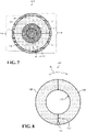
- FIG. 7 shows another, non-limiting front cross-sectional view of a portion of rotor 30 and protective cover 100B.
- seam 110 of liner 102, and seam 122 of outer casing 104 may be radially aligned.
- first liner portion 106 of liner 102 may be radially aligned with first section 118 of outer casing 104
- second liner portion 108 of liner 102 may be radially aligned with second section 120 of outer casing 104.
- FIG. 7 shows another, non-limiting front cross-sectional view of a portion of rotor 30 and protective cover 100B.
- liner 102, and its respective portions may in embodiments different from the herein claimed subject matter, be coupled to outer casing 104, and its respective, aligned sections. Specifically, first liner portion 106 of liner 102 may be coupled to first section 118 of outer casing 104, and second liner portion 108 of liner 102 may be coupled to second section 120 of outer casing 104.
- first liner portion 106 of liner 102 may be releasably coupled to first section 118 of outer casing 104
- second liner portion 108 of liner 102 may be releasably coupled to second section 120 of outer casing 104 using any suitable coupling technique and/or coupling component that is discussed herein or may otherwise maintain a coupling liner 102 and outer casing 104.
- liner portions 106, 108 of liner 102 may be removed from bearings 42A, 42B and/or rotor 30 when sections 118, 120 of outer casing 104 are uncoupled from bearings 42A, 42B and/or rotor 30.
- liner portions 106, 108 of liner 102 releasably coupled to corresponding sections 118, 120 of outer casing 104 may remain in contact and/or cover bearings 42A, 42B and/or rotor 30 when sections 118, 120 of outer casing 104 are uncoupled from bearings 42A, 42B and/or rotor 30.
- liner 102 may, in embodiments different from the herein claimed invention, be permanently affixed to outer casing 104, and its respective, aligned sections.
- first liner portion 106 of liner 102 may be permanently affixed to first section 118 of outer casing 104
- second liner portion 108 of liner 102 may be permanently affixed to second section 120 of outer casing 104.
- first liner portion 106 of liner 102 may be permanently affixed to first section 118 of outer casing 104
- second liner portion 108 of liner 102 may be permanently affixed to second section 120 of outer casing 104 using any suitable component joining technique and/or joining component that is discussed herein or may otherwise affix liner 102 to outer casing 104 (e.g., adhesive, melting, welding, soldering and so on).
- liner portions 106, 108 of liner 102 may be removed from bearings 42A, 42B and/or rotor 30 when sections 118, 120 of outer casing 104 are uncoupled from bearings 42A, 42B and/or rotor 30.
- first liner portion 106 may be removed with first section 118 and may no longer contact and/or cover the first portion of bearings 42A, 42B, features 48 and/or rotor 30, as discussed herein.
- FIGs. 8-13 show various non-limiting examples of first liner portion 106 coupled to second liner portion 108 to form liner 102 of protective cover 100A, 100B. It is understood that similarly numbered and/or named components may function in a substantially similar fashion. Redundant explanation of these components has been omitted for clarity.
- first liner portion 106 may be pivotally coupled to second liner portion 108.
- seam 110 formed between first liner portion 106 and second liner portion 108 may include a pivot coupling or joint 132 (hereafter, "pivot joint 132") that may be coupled to first liner portion 106 and second liner portion 108, respectively.
- pivot joint 132 a pivot coupling or joint 132
- first liner portion 106 and/or second liner portion 108 may be configured to move and/or rotate about pivot joint 132 in a direction (Di) to open liner 102.
- liner 102 may be opened by moving and/or rotating first liner portion 106 and/or second liner portion 108 about pivot joint 132 in a direction (Di) to place liner 102 around bearings 42A, 42B, features 48 and/or rotor 30.
- Pivot joint 132 may ensure first liner portion 106 and/or second liner portion 108 may be separated and/or opened wide enough to clear bearings 42A, 42B and/or rotor 30 during the installation process and/or avoid undesirable and/or unnecessary contact between liner 102 and rotor 30.
- FIGs. 10 and 11 show first liner portion 106 releasably coupled to second liner portion 108 via a fastener 134.
- FIG. 10 shows a front cross-sectional view of a portion of first liner portion 106 releasably coupled to second liner portion 108 via fastener 134
- FIG. 11 shows a bottom view of a portion of first liner portion 106 releasably coupled to second liner portion 108 via fasteners 134.
- second liner portion 108 may include a protrusion or tab 136 (hereafter, "tab 136") that may extend into and/or be seated into a recess 138 formed in first liner portion 106.
- tab 136 protrusion or tab 136
- tab 136 and recess 138 may be formed and/or span over the axial length of first liner portion 106 and second liner portion 108, respectively.
- second liner portion 108 may include a plurality of tabs 136
- first liner portion 106 may include corresponding recesses 138 for the plurality of tabs 136 that may be circumferentially aligned and configured to receive tabs 136, as discussed herein.
- Tab 136 of second liner portion 108 and a portion of first liner portion 106 radially aligned with tab 136 may receive fastener 134 for coupling and/or joining first liner portion 106 and second liner portion 108. As shown in FIG.
- first liner portion 106 and second liner portion 108 may be coupled to form liner 102 using a plurality of fasteners 134 (two shown) that may be spread out axially over first liner portion 106 and second liner portion 108.
- fastener 134 may be any suitable fastening or coupling component that may be utilized to releasably couple first liner portion 106 to second liner portion 108.
- fastener 134, tab 136 and recess 138 configuration may be included in a portion of liner 102 formed opposite the portion shown in FIG. 10 .
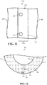
- FIGs. 12 and 13 show front cross-sectional views of a portion of first liner portion 106 releasably coupled to second liner portion 108 via a cantilever snap-fit 140.
- second liner portion 108 includes cantilever snap-fit 140 that extends into, contacts and/or is retained by a latch or slot 141 formed in first liner portion 106 to couple second liner portion 108 to first liner portion 106.
- cantilever snap-fit 140 may be formed directly adjacent and/or may be exposed on an exterior surface 142 of liner 102.
- cantilever snap-fit 140 may be engaged/disengaged for coupling/uncoupling first liner portion 106 and second liner portion 108 by manipulating and/or deflecting cantilever snap-fit 140 at exterior surface 142 of liner 102.
- cantilever snap-fit 140 may be positioned and/or formed within second liner portion 108. Specifically, cantilever snap-fit 140 may be formed within second liner portion 108 between contact surface 112 and exterior surface 142 of liner 102. Similar to the non-limiting example shown in FIG. 12 , cantilever snap-fit 140 formed in second liner portion 108 between contact surface 112 and exterior surface 142 may extend into, contact and/or may be retained by a latch or slot 141 formed in first liner portion 106. However, distinct from the non-limiting example shown in FIG.
- first liner portion 106 may include additional features where cantilever snap-fit 140 may be formed in second liner portion 108 between contact surface 112 and exterior surface 142. As shown in FIG. 13 , first liner portion 106 may include a through hole 144 formed through first liner portion 106 extending to and/or providing access to cantilever snap-fit 140. Through hole 144 may allow access to cantilever snap-fit 140 to ensure that cantilever snap-fit 140 is engaged for coupling first liner portion 106 and second liner portion 108.
- first liner portion 106 may provide access to cantilever snap-fit 140 to deflect and/or bend cantilever snap-fit 140 to disengage and/or uncouple second liner portion 108 from first liner portion 106.
- First liner portion 106 may also include a recess 146 radially aligned with cantilever snap-fit 140 and configured to receive and/or allow cantilever snap-fit 140 to be deflected and/or bend into recess 146 when engaging or disengaging cantilever snap-fit 140, as discussed herein.
- FIG. 14 shows a front cross-sectional view of protective cover 100B.
- liner 102 of protective cover 100B may be formed from three, distinct liner portions.
- liner 102 may include and/or be formed from first liner portion 106, second liner portion 108 and third liner portion 148.
- Third liner portion 148 may be positioned between and at least partially aligned, circumferentially and/or axially, with first liner portion 106 and/or second liner portion 108. Similar to first liner portion 106 and second liner portion 108, third liner portion 148 may contact and/or cover a third portion of bearings 42A, 42B, features 48 and/or rotor 30.
- third liner portion 148 may also include contact surface 112 that may include a geometry that may be similar and/or correspond to a shape and/or profile of third portion of bearings 42A, 42B, features 48 and/or rotor 30, as similarly discussed herein with respect to contact surfaces 112 of first liner portion 106 and/or second liner portion 108.
- FIGs. 15 and 16 show a side view of a portion of rotor 30 and protective cover 100B in accordance with the herein claimed subject matter. Distinct from protective covers previously discussed herein, protective cover 100B shown in FIGs. 15 and 16 includes outer casing 104 substantially formed as a single, unibody. More specifically, outer casing 104 is not formed from distinct sections that are separated and/or joined a seam (see, FIGs. 3-6 ), but rather, outer casing 104 shown in FIGs. 15 and 16 includes a single, substantially solid unibody that is configured to be positioned over and/or slidingly engage liner 102 to form protective cover 100B. As shown in FIG. 15 , unibody outer casing 104 includes an opening 150 formed opposite endwall 126.
- Opening 150 is configured to receive liner 102 and/or allow unibody outer casing 104 to move in a direction (D 2 ) (see, FIG. 15 ) to substantially cover and/or slidingly engage liner 102 and any liner portions (e.g., first liner portion 106, second liner portion 108) forming liner 102.
- unibody outer casing 104 is configured to form a compression-fit on liner 102 to hold or secure liner 102 to bearings 42A, 42B and/or rotor 30.
- endwall 126 of unibody outer casing 104 may be solid and/or continuous, and may be configured to cover and/or encompass distal end 46 of shaft 30.
- protective cover 100B may also include an end plate 152. Similar to endwalls 124, 126 discussed herein, end plate 152 may be utilized to substantially enclose protective cover 100A and/or enclose or surround liner 102. End plate 152 may be releasably coupled to unibody outer casing 104, and may substantially surround, contact, be coupled to and/or be positioned on rotor 30.
- end plate 152 may be formed as two distinct sections or halves and may include aperture 128 formed therein for receiving and/or allowing rotor 30 to pass through end plate 152 to couple protective covers 100B and/or unibody outer casing 104 to bearings 42A, 42B and/or rotor 30.
- sealing ring 130 may be positioned within or may be positioned adjacent aperture 128 formed through end plate 152, and may also be positioned around, contact and/or coupled to rotor 30.
- sealing ring 130 may be configured to seal outer casing 104 and enclose liner 102, such that there is no access to bearing 42B, features 48 and/or rotor 30 covered and/or protected by protective covers 100B.
- FIG. 17 shows a front cross-sectional view of protective cover 100B.
- protective cover 100B may also include a sleeve 154.
- Sleeve 154 may surround first liner portion 106 and second liner portion 108 forming liner 102.
- sleeve 154 may be positioned and/or formed between liner 102 and outer casing 104. That is, outer casing 104 may substantially cover and/or contact sleeve 154 surrounding liner 102.
- sleeve 154 may be formed as a solid, continuous, unibody with two openings (not shown) formed on opposite ends.
- sleeve 154 may slidingly engage and/or form a compression-fit around first liner portion 106 and second liner portion 108, similar to that of unibody outer casing 104 discussed herein with respect to FIGs. 15 and 16 .
- Sleeve 154 may be formed from any suitable material that may be capable of being slid over liner 102 and/or form a compression-fit around liner 102.
- sleeve 154 may be formed from foam, polymers including rubber, plastic and the like.
- sleeve 154 may include an adjustable diameter, such that after sleeve 154 is slid over and/or circumferentially/axially aligned with liner 102, the diameter of sleeve 154 may be adjusted so sleeve 154 may contact and/or form a compression-fit around liner 102.
- FIGs. 18-21 show another, non-limiting example of protective cover 100B.
- FIG. 18 shows a front cross-sectional view of protective cover 100B including a deformable, uniform liner 102
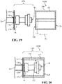
- FIGs. 19-21 show a side view of a portion of rotor 30 and protective cover 100B including deformable uniform liner 102.
- deformable, uniform liner 102 of protective cover 100B may include a uniform thickness (T) over the axial length of liner 102.
- contact surface 112 of deformable, uniform liner 102 may be substantially uniform, planar, and/or may not initially include any geometries similar to bearing 42B, features 48 and/or rotor 30 (see, FIG. 19 ), as discussed herein.
- deformable, uniform liner 102, as well as outer casing 104 may be formed as a single, unibody liner for protective cover 100B.
- deformable, uniform liner 102 and/or outer casing 104 of protective cover 100B may be formed from various portions and/or sections, as similarly discussed herein.
- deformable, uniform liner 102 may not initially (e.g., before contacting bearing 42B and/or rotor 30) include a geometry that may be similar to the shape and/or profile of bearing 42B, features 48 and/or rotor 30, as discussed herein. Rather, deformable, uniform liner 102 may conform and/or take the shape or profile of bearing 42B, features 48 and/or rotor 30 after being positioned around and/or aligned with bearing 42B, features 48 and/or rotor 30.
- deformable, uniform liner 102 may be formed from a material that may include malleable, deformable and/or compressible characteristics, as well as, elastic characteristics, such that deformable, uniform liner 102 may take, conform and/or match the shapes and/or profiles of bearing 42B, features 48 and/or rotor 30 after being positioned around the same. As shown in FIG. 20 , deformable, uniform liner 102 may be compressed to allow deformable, uniform liner 102 and/or outer casing 104 to move over and/or surround bearing 42B, features 48 and/or rotor 30. Additionally, deformable, uniform liner 102 may be compressed to avoid undesirable contact with bearing 42B, features 48 and/or rotor 30.
- deformable, uniform liner 102 may begin to return to its original, uniform and/or planar geometry based on liner's 102 elastic characteristics.
- deformable, uniform liner 102 includes malleable characteristics, and because the profile of bearing 42B, features 48 and/or rotor 30 is dimensionally (e.g., diameter) larger than the diameter of the space or opening formed through liner 102, liner 102 may cover, contact and/or substantially contour to the profile of bearing 42B, features 48 and/or rotor 30 (see, FIG. 21 ).
- deformable, uniform liner 102 of protective cover 100B shown in FIGs. 18-21 may be formed from foam.
- FIGs. 22-24 show various, non-limiting examples of a shipping apparatus for rotor 30.
- shipping apparatus 156 may be utilized to ship rotor 30 and may utilize protective covers 100A, 100B to protect bearings 42A, 42B and/or rotor 30 during the shipping process. It is understood that similarly numbered and/or named components may function in a substantially similar fashion. Redundant explanation of these components has been omitted for clarity.
- shipping apparatus 156 may include a base 158, and a plurality of supports 160 extending from base 158. Specifically, the plurality of supports 160 may extend upwards from and/or away from base 158.
- the plurality of supports 160 of shipping apparatus 156 may be configured to receive and/or support rotor 30. In the in non-limiting examples shown in FIGs. 22-24 rotor 30 may be supported by, may be coupled to and/or may rest on the plurality of supports 160 of shipping apparatus 156.
- Each of the plurality of supports 160 of shipping apparatus 156 may contact and/or receive rotor 30 adjacent to protective covers 100A, 100B surrounding, covering and/or protecting bearings 42A, 42B and/or rotor 30. That is, the plurality of supports 160 may not overlap with and/or receive any portion of protective covers 100A, 100B.
- protective cover 100B may be coupled to shipping apparatus 156. That is, protective cover 100B may be coupled or affixed, directly or indirectly, to base 158 or support 160 of shipping apparatus 156. Protective cover 100B may be coupled or affixed to shipping apparatus 156 so protective cover 100B may be reused by shipping apparatus 156 when shipping various, distinct rotors 30 that may utilize protective cover 100B.
- outer casing 104 of protective cover 100B may include an extended segment 162 that may extend toward and contact or be coupled to base 158 of shipping apparatus 156.
- Extended segment 162 may be a portion of outer casing 104, but may act as a coupling and/or support for outer casing 104 of protective cover 100B by extending between and being coupled to base 158 of shipping apparatus 156.
- extended segment 162 may be coupled to base 158 and may be formed integral with a section (e.g., second section 120; see, FIG.
- outer casing 104 may be substantially aligned with and/or surround a bottom portion (e.g., radial bottom half) of bearing 42B and/or rotor 30.
- extended segment 162 of outer casing 104 may be releasably coupled to or pivotally coupled to base 158 of shipping apparatus 156.
- Extended segment 162 may be releasably coupled to or pivotally coupled to base 158 of shipping apparatus 156 to aid in the removal of protective cover 100B, and/or its various component (e.g., outer casing 104, liner 102) from rotor 30.
- shipping apparatus 156 may include a strut 164 positioned between base 158 and outer casing 104 of protective cover 100B.
- strut 164 may be positioned between and may be coupled or affixed to base 158 of shipping apparatus 156 and outer casing 104 of protective cover 100B, respectively.
- strut 164 may be releasably coupled to or pivotally coupled to outer casing 104 of protective cover 100B at interface 166.
- Outer casing 104 of protective cover 100B may be releasably coupled to or pivotally coupled to strut 164 of shipping apparatus 156 at interface 166 to aid in the removal of protective cover 100B, and/or its various component (e.g., outer casing 104, liner 102) from rotor 30. Additionally, outer casing 104 of protective cover 100B may be releasably coupled to or pivotally coupled to strut 164 at interface 166 to aid in the removal of rotor 30 from portions of protective cover 100B that may not be uncoupled from shipping apparatus 156 and/or strut 164.
- protective cover 100B may be coupled directly to support 160 of shipping apparatus 156. Specifically, at least a portion of endwall 124 of outer casing 104 of protective cover 100B may be coupled or affixed to support 160 of shipping apparatus 156. As similarly discussed herein, endwall 124 of outer casing 104 may be releasably coupled to or pivotally coupled to support 160 of shipping apparatus 156 to aid in the removal of protective cover 100B from rotor 30, and/or aid in the removal of rotor 30 from protective cover 100B.
- protective cover 100B is shown to be coupled to shipping apparatus 156, it is understood that protective cover 100A may be coupled to shipping apparatus 156 in any similar fashion or manner discussed herein with respect to protective cover 100B.
- the protective covers discussed herein may be utilized to cover, contact and/or protect any portion of the rotor during a shipping process. That is, any portion of a rotor for a turbine system may utilize the protective covers discussed herein to prevent undesired contact and/or damage to portions of the rotor during moving, removal and/or shipping processes.
- the protective covers discussed herein may be utilized to protect compressor blades and/or turbine blades that may be coupled to the rotor.
- protective covers may be used in other applications, other than rotors for gas turbine systems. That is, protective covers may be utilized by any rotor of a mechanical system, or may be used to protect any substantially linear component or device during shipping and/or transportation process.
- Approximating language may be applied to modify any quantitative representation that could permissibly vary without resulting in a change in the basic function to which it is related. Accordingly, a value modified by a term or terms, such as “about,” “approximately” and “substantially,” are not to be limited to the precise value specified. In at least some instances, the approximating language may correspond to the precision of an instrument for measuring the value.
- range limitations may be combined and/or interchanged, such ranges are identified and include all the sub-ranges contained therein unless context or language indicates otherwise. "Approximately” as applied to a particular value of a range applies to both values, and unless otherwise dependent on the precision of the instrument measuring the value, may indicate +/- 10% of the stated value(s).
Landscapes
- Engineering & Computer Science (AREA)
- Mechanical Engineering (AREA)
- General Engineering & Computer Science (AREA)
- Structures Of Non-Positive Displacement Pumps (AREA)
Description
- The disclosure relates generally to protective covers, and more particularly, to a protective cover for a rotor of a turbine system and shipping apparatuses that utilizes the protective cover when shipping and/or transporting rotors.
- Due to the dimensions and intricacies of the features included in turbine rotors, it is often difficult to safely and effectively to move or transport rotors. Whether it is removing a turbine rotor from the turbine system to perform standard maintenance procedures, or shipping a new rotor to be utilized in a turbine system, rotors and their various features or components are susceptible to undesirable contact, which may result in damage to the rotor. The damage caused by undesirable contact may result in operational inefficiencies, extra required maintenance, and in some cases, replacement of components, features or the entire rotor. Damage to the rotor and its features can be costly and time consuming for operators of turbine systems.
- Conventional shipping methods utilize standard packaging material and procedures to attempt to reduce damage to the rotors during transport. For example, bearings and blade areas of a rotor are typically wrapped in various layers of plastic wrap for protection. Additionally, cardboard is often placed over these areas prior to and/or in between layers of wrapping to provide additional layers of protection. However, plastic wrap and cardboard do not provide an adequate amount of protection for the rotor; especially for portions of components like the rotor bearings, which are highly sensitive to undesirable contact. Furthermore, once the rotor reaches its destination, the only way to remove this plastic wrap and cardboard is to cut it from the rotor. As a result, even if the rotor and its components are not damaged during the transportation or shipping process, the rotor may become damaged if a person cutting away the plastic wrap and cardboard cuts too deeply and undesirably contacts or cuts the rotor.
- Various protection and transport systems are known from
US 3401791 ,DE 2937187 ,US 4032255 andFR 2761668 - A first aspect of the disclosure provides a protective cover for a rotor. The protective cover includes a first liner portion being able to contact and cover a first portion of the rotor; a second liner portion positioned adjacent and at least partially aligned circumferentially with the first liner portion, the second liner portion being able to contact and cover a second portion of the rotor; and an outer casing covering the first liner portion and the second liner portion, wherein the outer casing slidingly engages and forms a compression-fit around the first liner portion and the second liner portion.
- A second aspect of the disclosure provides a shipping apparatus for a rotor. The shipping apparatus includes a base; a plurality of supports extending from the base, the plurality of supports configured to receive and support the rotor; and a protective cover for the rotor, the protective cover coupled to the base and including: a first liner portion being able to contact and cover a first portion of the rotor; a second liner portion positioned adjacent and at least partially aligned circumferentially with the first liner portion, the second liner portion being able to contact and cover a second portion of the rotor; and an outer casing covering the first liner portion and the second liner portion, wherein the outer casing slidingly engages and forms a compression-fit around the first liner portion and the second liner portion.
- The illustrative aspects of the present disclosure are designed to solve the problems herein described and/or other problems not discussed.
- These and other features of this disclosure will be more readily understood from the following detailed description of the various aspects of the disclosure taken in conjunction with the accompanying drawings that depict various embodiments of the disclosure, in which:
-
FIG. 1 shows a schematic diagram of a gas turbine system according to embodiments. -
FIG. 2 shows a side view of a portion of the rotor for the gas turbine system ofFIG. 1 , according to embodiments. -
FIG. 3 shows a perspective view of the rotor ofFIG. 2 and protective covers, according to embodiments. -
FIG. 4 shows a front cross-sectional view of the protective cover ofFIG. 3 , according to embodiments. -
FIGs. 5 and 6 show side cross-sectional views of the rotor ofFIG. 2 and protective covers, according to embodiments. -
FIG. 7 shows a front cross-sectional view of a protective cover, according to additional embodiments. -
FIGs. 8 and9 show front cross-sectional views of a pivotally coupled liner of a protective cover, according to embodiments. -
FIG. 10 shows a front cross-sectional view of a portion of a liner of a protective cover including a fastener, according to embodiments. -
FIG. 11 shows a top view of the portion of the liner of the protective cover including the fastener ofFIG. 10 , according to embodiments. -
FIG. 12 shows a front cross-sectional view of a portion of a liner of a protective cover including a snap-fit, according to embodiments. -
FIG. 13 shows a front cross-sectional view of a portion of a liner of a protective cover including a snap-fit, according to additional embodiments. -
FIG. 14 shows a front cross-sectional view of a protective cover, according to further embodiments. -
FIGs. 15 and 16 show side views of a portion of a rotor and a protective cover including a unibody outer casing, according to embodiments. -
FIG. 17 shows a front cross-sectional view of a protective cover including a sleeve, according to embodiments. -
FIG. 18 shows a front cross-sectional view of a protective cover including a deformable, uniform liner, according to embodiments. -
FIGs. 19-21 show side views of a portion of a rotor and the protective cover including the deformable, uniform liner ofFIG. 18 , according to embodiments. -
FIGs. 22-24 show side views of a portion of a rotor, protective covers and a shipping apparatus, according to various embodiments. - It is noted that the drawings of the disclosure are not to scale. The drawings are intended to depict only typical aspects of the disclosure, and therefore should not be considered as limiting the scope of the disclosure. In the drawings, like numbering represents like elements between the drawings.
- As an initial matter, in order to clearly describe the current disclosure it will become necessary to select certain terminology when referring to and describing relevant machine components within the scope of this disclosure. When doing this, if possible, common industry terminology will be used and employed in a manner consistent with its accepted meaning. Unless otherwise stated, such terminology should be given a broad interpretation consistent with the context of the present application and the scope of the appended claims. Those of ordinary skill in the art will appreciate that often a particular component may be referred to using several different or overlapping terms. What may be described herein as being a single part may include and be referenced in another context as consisting of multiple components. Alternatively, what may be described herein as including multiple components may be referred to elsewhere as a single part.
- In addition, several descriptive terms may be used regularly herein, and it should prove helpful to define these terms at the onset of this section. These terms and their definitions, unless stated otherwise, are as follows. As used herein, "downstream" and "upstream" are terms that indicate a direction relative to the flow of a fluid, such as the working fluid through the turbine engine or, for example, the flow of air through the combustor or coolant through one of the turbine's component systems. The term "downstream" corresponds to the direction of flow of the fluid, and the term "upstream" refers to the direction opposite to the flow. The terms "forward" and "aft," without any further specificity, refer to directions, with "forward" referring to the front or compressor end of the engine, and "aft" referring to the rearward or turbine end of the engine. Additionally, the terms "leading" and "trailing" may be used and/or understood as being similar in description as the terms "forward" and "aft," respectively. It is often required to describe parts that are at differing radial, axial and/or circumferential positions. The "A" axis represents an axial orientation. As used herein, the terms "axial" and/or "axially" refer to the relative position/direction of objects along axis A, which is substantially parallel with the axis of rotation of the turbine system (in particular, the rotor section). As further used herein, the terms "radial" and/or "radially" refer to the relative position/direction of objects along an axis "R" (see,
FIG. 1 ), which is substantially perpendicular with axis A and intersects axis A at only one location. Finally, the term "circumferential" refers to movement or position around axis A (e.g., axis "C"). - The following disclosure relates generally to protective covers, and more particularly, to a protective cover for a rotor of a turbine system and shipping apparatuses that utilizes the protective cover when shipping and/or transporting rotors.
- These and other embodiments are discussed below with reference to
FIGs. 1-24 . However, those skilled in the art will readily appreciate that the detailed description given herein with respect to these Figures is for descriptive purposes only and should not be construed as limiting. -
FIG. 1 shows a schematic view of an illustrative gas turbine system that may include a rotor as may be protected by a cover.Gas turbine system 10 may include acompressor 12.Compressor 12 compresses an incoming flow ofair 18.Compressor 12 delivers a flow ofcompressed air 20 to a combustor 22. Combustor 22 mixes the flow ofcompressed air 20 with a pressurized flow offuel 24 and ignites the mixture to create a flow ofcombustion gases 26. Although only a single combustor 22 is shown,gas turbine system 10 may include any number of combustors 22. The flow ofcombustion gases 26 is in turn delivered to aturbine 28, which typically includes a plurality of turbine blades (see,FIG. 2 ) and stator vanes. The flow ofcombustion gases 26 drivesturbine 28 to produce mechanical work. The mechanical work produced inturbine 28 drivescompressor 12 via arotor 30 extending throughturbine 28, and may be used to drive anexternal load 32, such as an electrical generator and/or the like. -
Gas turbine system 10 may also include anexhaust frame 34. As shown inFIG. 1 ,exhaust frame 34 may be positionedadjacent turbine 28 ofgas turbine system 10. More specifically,exhaust frame 34 may be positioned adjacent toturbine 28 and may be positioned substantially downstream ofturbine 28 and/or the flow ofcombustion gases 26 flowing from combustor 22 toturbine 28. As discussed herein, a portion (e.g., outer casing) ofexhaust frame 34 may be coupled directly to an enclosure orshell 36 ofturbine 28. - Subsequent to
combustion gases 26 flowing through and drivingturbine 28,combustion gases 26 may be exhausted, flow-through and/or discharged throughexhaust frame 34 in a flow direction (D). In the non-limiting example shown inFIG. 1 ,combustion gases 26 may flow throughexhaust frame 34 in the flow direction (D) and may be discharged from gas turbine system 10 (e.g., to the atmosphere). In another non-limiting example wheregas turbine system 10 is part of a combined cycle power plant (e.g., including gas turbine system and a steam turbine system),combustion gases 26 may discharge fromexhaust frame 34, and may flow in the flow direction (D) into a heat recovery steam generator of the combined cycle power plant. - Turning to
FIG 2 , and with continued reference toFIG. 1 , a portion ofrotor 30 ofgas turbine system 10 is shown. As discussed hereinrotor 30 may include a plurality ofturbine blades 38 that may be coupled torotor 30 and may be driven bycombustion gases 26 to rotaterotor 30. Additionally as shown inFIG. 2 ,rotor 30 may include aplurality compressor blades 40.Compressor blades 40 may be coupled torotor 30 and may positioned and/or housed withincompressor 12 of gas turbine system 10 (see,FIG. 1 ). In the non-limiting example shown inFIGs. 1 and 2 , asrotor 30 rotates,compressor blades 40 may also rotate to generate compressed air 20 (see,FIG. 1 ), whileturbine blades 38 are driven bycombustion gases 26 to rotaterotor 30. Not all ofturbine blades 38,compressor blades 40 and/orrotor 30 are shown for clarity. -
Rotor 30 may also includebearings 42A, 42B. Specifically, and as shown inFIG. 2 ,rotor 30 may include asingle bearing 42A, 42B positioned adjacent eachdistal end rotor 30. In anon-limiting example, first bearing 42A positioned adjacentdistal end 44 may be positioned within and/or supported bycompressor 12 of gas turbine system 10 (see,FIG. 1 ). In another non-limiting example, first bearing 42A may be positioned outside ofcompressor 12, opposite turbine 28 (see,FIG. 1 ), and may be supported by a bearing housing or support (not shown).Second bearing 42B positioned adjacentdistal end 46 may be positioned within and/or supported byexhaust frame 34 of gas turbine system 10 (see,FIG. 1 ), or alternatively, may be supported by a bearing housing or support (not shown) positioned adjacent exhaust frame 34 (see,FIG. 1 ). As shown inFIG. 2 , each bearing 42A, 42B may include components, elements and/or features 48 (hereafter, "features 48").Features 48 may be coupled to, formed on and/or attached torotor 30. Additionally, features 48 ofbearings 42A, 42B may extend radially from and/or (at least partially) circumferentially aroundrotor 30.Features 48 ofbearings 42A, 42B may be formed onrotor 30 to aid and/or improve the rotation or drive ofrotor 30 during operation of gas turbine system 10 (see,FIG. 1 ). In non-limiting examples, features 48 ofbearings 42A, 42B may include collars, oil housings or wells, and/or any other suitable feature included in bearings for rotors of turbine systems. -
FIG. 3 shows a perspective view of a portion ofrotor 30 andprotective covers Turbine blades 38 andcompressor blades 40 have been removed fromrotor 30 inFIG. 3 for clarity. As shown inFIG. 3 ,protective covers bearings 42A, 42B (shown in phantom), respectively, ofrotor 30. Specifically,protective covers bearings 42A, 42B and a portion ofrotor 30 positioned within and/or directly adjacent tobearings 42A, 42B. As shown inFIG. 3 , and discussed in detail below,protective covers bearings 42A, 42B androtor 30.Rotor 30 may utilizeprotective covers bearings 42A, 42B from being exposed whenrotor 30 is being transported, moved and/or removed fromgas turbine system 10, for example, to perform maintenance onrotor 30 and/or other components ofgas turbine system 10. It is understood that "protective cover" and "cover" may be used interchangeably throughout this disclosure. As such, any reference to "cover 100A, 100B" may be understood or interpreted as "protective cover -
FIGs. 4-6 show various cross-sectional views ofrotor 30 andprotective covers FIG. 3 . Specifically,FIG. 4 shows a cross-sectional front view ofrotor 30 andprotective cover 100B taken along line R-R inFIG. 3 ,FIG. 5 shows a cross-sectional side view ofrotor 30 andprotective covers FIG. 3 , andFIG. 6 shows a cross-sectional side view ofrotor 30 andprotective covers FIG. 3 , where a portion ofprotective cover 100A is exploded fromrotor 30. It is understood that similarly numbered and/or named components may function in a substantially similar fashion. Redundant explanation of these components has been omitted for clarity. - With reference to
FIGs. 3-6 , eachprotective cover FIG. 3 ) and anouter casing 104. As shown inFIGs. 3-6 ,liner 102 ofprotective covers circumferentially surround bearings 42A, 42B ofrotor 30. Additionally, and as discussed herein,liner 102 may contact and substantially covers bearing 42A, 42B ofrotor 30 to protect and/or prevent damage tobearings 42A, 42B of rotor.Liner 102 may be coupled or fixed toouter casing 104, or alternatively, in accordance with the claimed subject matter, may be merely in contact (e.g., compression fit) withouter casing 104. As shown inFIGs. 3-6 ,outer casing 104 in the shown embodimentsubstantially surrounds, contacts and/or coversliner 102 ofprotective covers rotor 30. Additionally, and as discussed herein,outer casing 104 may contact and/or be (releasably) coupled torotor 30 to secureprotective cover rotor 30 and/or to coverbearings 42A, 42B.Outer casing 104 may secureliner 102 tobearings 42A, 42B and/orrotor 30 and/or may form a protective and/or rigid exterior shell aroundbearings 42A, 42B. -
Liner 102 and/orouter casing 104 formingprotective covers FIG. 4 ,liner 102 is formed from afirst liner portion 106 and asecond liner portion 108.First liner portion 106 andsecond liner portion 108 may be substantially aligned with each other when surroundingbearings 42A, 42B and/orrotor 30, as in the embodiments offigures 3-6 . More specifically,second liner portion 108 may be positioned adjacent to, and may be at least partially aligned circumferentially and/or axially withfirst liner portion 106, as in the embodiments offigures 3-6 . Additionally in the non-limiting example,first liner portion 106 may contact a first portion or area (e.g., radially upper half) ofbearings 42A, 42B, features 48 and/orrotor 30, whilesecond liner portion 108 may contact a second portion or area (e.g., radially bottom half) ofbearings 42A, 42B, features 48 and/orrotor 30. The first portion of bearingbearings 42A, 42B, features 48 and/orrotor 30 may be circumferentially and/or axially aligned with the second portion ofbearings 42A, 42B, features 48 and/orrotor 30. As a result of the substantial alignment offirst liner portion 106 andsecond liner portion 108, both first and second portions ofbearings 42A, 42B, features 48 and/orrotor 30 may be completely and/or collectively covered byfirst liner portion 106 andsecond liner portion 108. In another non-limiting example where features 48 ofbearings 42A, 42B may not extend completely around rotor 30 (e.g., open-ring feature),first liner portion 106 andsecond liner portion 108 may not be completely and/or fully aligned, and only one of theliner portions ring feature 48. - As a result of
liner 102 being formed from distinct,first liner portion 106 andsecond liner portion 108, an interface orseam 110 may be formed betweenfirst liner portion 106 andsecond liner portion 108 formingliner 102. In a non-limiting example shown inFIG. 4 , and discussed in detail herein,first liner portion 106 andsecond liner portion 108 formingliner 102 may contact one another atseam 110 and is held in place byouter casing 104. Specifically, in the shown embodiment,outer casing 104 substantially surrounds and/or coversfirst liner portion 106 andsecond liner portion 108 formingliner 102, and may, in accordance with the claimed subject matter, form a compression-fit onfirst liner portion 106 andsecond liner portion 108 in order to hold or securefirst liner portion 106 andsecond liner portion 108 tobearings 42A, 42B and/orrotor 30. In other non-limiting examples discussed herein,first liner portion 106 andsecond liner portion 108 may be coupled to each other at and/oradjacent seam 110 whenprotective covers rotor 30 to protectbearings 42A, 42B. - In the non-limiting example shown in
FIG. 4 ,first liner portion 106 andsecond liner portion 108 may, in accordance with the claimed subject matter, contactouter casing 104, but may, also in accordance with the claimed subject matter, not be coupled toouter casing 104. That is, whereouter casing 104 forms a compression-fit onfirst liner portion 106 andsecond liner portion 108,first liner portion 106 andsecond liner portion 108 ofliner 102 contact and/or are contacted byouter casing 104, but may not be permanently coupled to, affixed and/or attached toouter casing 104. As a result, whenouter casing 104 is removed fromrotor 30, and no longer applying a compression-fit onliner 102,first liner portion 106 andsecond liner portion 108 ofliner 102 may remain attached, coupled to and/or coveringbearings 42A, 42B ofrotor 30. In other non-limiting examples discussed herein,first liner portion 106 andsecond liner portion 108 ofliner 102 may be (releasably) coupled to or permanently affixed to outer casing 104 (see,FIG. 7 ). - It is understood that the number of portions (e.g.,
first liner portion 106, second liner portion 108) used to formliner 102 is merely illustrative. Although two portions are shown and described herein to formliner 102, it is understood that more (see,FIG. 14 ) portions may be utilized to formliner 102 ofprotective covers - As shown in
FIGs. 4-6 , and specificallyFIG. 6 ,liner 102 may include acontact surface 112 that may contactbearings 42A, 42B, features 48 and/orrotor 30. More specifically, each offirst liner portion 106 andsecond liner portion 108 may includecontact surface 112 that may touch, cover and/or contact the corresponding portion (e.g., first portion, second portion) ofbearings 42A, 42B, features 48 and/orrotor 30. As shown inFIG. 6 ,contact surface 112 may include a geometry substantially similar to and/or corresponding to features 48 ofbearings 42A, 42B and/orrotor 30. That is,contact surface 112 offirst liner portion 106 may include a geometry substantially similar to and/or corresponding to at least a portion of feature(s) 48 included in the first portion ofbearings 42A, 42B and/orrotor 30 thatfirst liner portion 106 is aligned with, contacts and/or surrounds. Additionally,contact surface 112 ofsecond liner portion 108 may include a geometry substantially similar to and/or corresponding to at least a portion of feature(s) 48 included in the second portion ofbearings 42A, 42B and/orrotor 30 thatsecond liner portion 108 is aligned with, contacts and/or surrounds. The geometry ofcontact surface 112 may be similar to, correspond to and/or be inverse to the shapes and/or profiles ofbearings 42A, 42B, features 48 and/orrotor 30. For example, the shapes and/or profiles ofbearings 42A, 42B, features 48 and/orrotor 30 may be considered the male-component, and the geometry ofcontact surface 112 may be consider the female-component. As such, the geometry ofcontact surface 112 formed infirst liner portion 106 andsecond liner portion 108, respectively, may cover, contact and receive corresponding portions ofbearings 42A, 42B, features 48 and/orrotor 30. In the non-limiting example shown inFIGs. 3-6 , the geometry ofcontact surface 112 may be prefabricated intofirst liner portion 106 andsecond liner portion 108 formingliner 102, and may be dependent and/or specific to the shapes and/or profiles ofbearings 42A, 42B, features 48 and/orrotor 30. In other non-limiting examples, the geometry ofcontact surface 112 may be formed and/or shaped in-place or afterliner 102contacts bearings 42A, 42B, features 48 and/or rotor 30 (see,FIGs. 18-21 ). -
Liner 102, and specificallyfirst liner portion 106 andsecond liner portion 108, may be formed from a material having malleable/deformable and/or elastic characteristics. For example,first liner portion 106 andsecond liner portion 106 formingliner 102 ofprotective covers liner 102 ofprotective covers bearings 42A, 42B, features 48 and/orrotor 30, including, but not limited to: foam, thermal plastics, textiles and the like. - Similar to
liner 102,outer casing 104 may be formed of distinct sections. That is,outer casing 104 may be formed from afirst section 118 and asecond section 120. As shown inFIGs. 3-6 ,second section 120 ofouter casing 104 may be positioned adjacent to, and may be aligned circumferentially and/or axially withfirst section 118 when surroundingliner 102.Outer casing 104 may also include an interface orseam 122 formed betweenfirst section 118 andsecond section 120 formingouter casing 104. In a non-limiting example shown inFIG. 4 , and discussed in detail herein,first section 118 andsecond section 120 formingouter casing 104 may contact one another atseam 122 and may be coupled to one another to remain in place whenprotective cover bearings 42A, 42B and/orrotor 30. That is,second section 120 may be releasably coupled tofirst section 118 ofouter casing 104 maintainouter casing 104 in position when coveringbearings 42A, 42B and/orrotor 30 and/or for providing a compression-fit tofirst liner portion 106 andsecond liner portion 108, as discussed herein.First section 118 andsecond section 120 ofouter casing 104 may be releasably coupled to one another using any suitable coupling technique and/or coupling component that is discussed herein or may otherwise maintain a coupling between thesections - It is understood that the number of sections (e.g.,
first section 118, second section 120) used to formouter casing 104 is merely illustrative. Although two sections are shown and described herein to formouter casing 104, it is understood that more or less (e.g., single, unitary-body outer casing) (see,FIGs. 16 and17 ) sections may be utilized to formouter casing 104 ofprotective covers - Each of
first section 118 andsecond section 120 formingouter casing 104 may includeendwalls FIGs. 3 ,5 and 6 ,first section 118 andsecond section 120 may include corresponding portions ofendwalls protective cover surround liner 102.Endwalls outer casing 104 may substantially surround, contact, be coupled to and/or be positioned onrotor 30 for couplingprotective covers outer casing 104, torotor 30. In the non-limiting example shown inFIGs. 3 ,5 and 6 , endwalls 124, 126 ofouter casing 104 forprotective cover 100A and endwall 124 ofouter casing 104 forprotective cover 100B may also include anaperture 128 formed therein.Aperture 128 may be formed inendwalls outer casing 104 to receive and/or allowrotor 30 to pass throughouter casing 104 to coupleprotective covers outer casing 104 tobearings 42A, 42B and/orrotor 30. - To ensure and/or improve the coupling of
outer casing 104 torotor 30, and/or to seal and substantially encloseliner 102 usingouter casing 104,protective cover sealing ring 130. Sealing rings 130 may be positioned within or may be positionedadjacent apertures 128 formed throughendwalls outer casing 104, and may also be positioned around, contact and/or coupled torotor 30. As shown inFIGs. 5 and 6 , sealing rings 130 may be configured to sealouter casing 104 and encloseliner 102, such that there is no access tobearings 42A, 42B, features 48 and/orrotor 30 covered and/or protected byprotective covers - In another non-limiting example, endwalls 124, 126 of
outer casing 104 may be substantially solid, continuous and/or may not includeaperture 128. As shown in theFIGs 3 ,5 and 6 , endwall 126 ofouter casing 104 forprotective cover 100B may be substantially solid, continuous and/or may not includeaperture 128. As such the corresponding portions ofendwall 126 for each offirst section 118 andsecond section 120 ofprotective cover 100B may also be substantially solid, continuous and/or may not includeaperture 128, and may only be separated byseam 122. In this non-limiting example, and as specifically shown inFIG. 5 ,protective cover 100B, includingliner 102 andouter casing 104, may substantially encompass and/or completely surrounddistal end 46 ofrotor 30, such thatdistal end 46 is not exposed whenprotective cover 100B covers, surrounds and/or protects bearing 42B and/orrotor 30, as discussed herein. -
Outer casing 104, and specificallyfirst section 118 andsecond section 120, may be formed from a material having substantially rigid characteristics. For example,first section 118 andsecond section 120 formingouter casing 104 ofprotective covers outer casing 104 ofprotective covers bearings 42A, 42B, features 48 and/orrotor 30, including, but not limited to, ceramics, wood, and the like. -
FIG. 7 shows another, non-limiting front cross-sectional view of a portion ofrotor 30 andprotective cover 100B. As shown inFIG. 7 , and distinct fromFIG. 4 ,seam 110 ofliner 102, andseam 122 ofouter casing 104 may be radially aligned. As a result,first liner portion 106 ofliner 102 may be radially aligned withfirst section 118 ofouter casing 104, andsecond liner portion 108 ofliner 102 may be radially aligned withsecond section 120 ofouter casing 104. Additionally in the non-limiting example shown inFIG. 7 ,liner 102, and its respective portions, may in embodiments different from the herein claimed subject matter, be coupled toouter casing 104, and its respective, aligned sections. Specifically,first liner portion 106 ofliner 102 may be coupled tofirst section 118 ofouter casing 104, andsecond liner portion 108 ofliner 102 may be coupled tosecond section 120 ofouter casing 104. In non-limiting example,first liner portion 106 ofliner 102 may be releasably coupled tofirst section 118 ofouter casing 104, andsecond liner portion 108 ofliner 102 may be releasably coupled tosecond section 120 ofouter casing 104 using any suitable coupling technique and/or coupling component that is discussed herein or may otherwise maintain acoupling liner 102 andouter casing 104. Whereliner portions liner 102 are releasably coupled to correspondingsections outer casing 104,liner portions liner 102 may be removed frombearings 42A, 42B and/orrotor 30 whensections outer casing 104 are uncoupled frombearings 42A, 42B and/orrotor 30. Alternatively,liner portions liner 102 releasably coupled to correspondingsections outer casing 104, may remain in contact and/or coverbearings 42A, 42B and/orrotor 30 whensections outer casing 104 are uncoupled frombearings 42A, 42B and/orrotor 30. - In another non-limiting example shown in
FIG. 7 ,liner 102, and its respective portions, may, in embodiments different from the herein claimed invention, be permanently affixed toouter casing 104, and its respective, aligned sections. Specifically,first liner portion 106 ofliner 102 may be permanently affixed tofirst section 118 ofouter casing 104, andsecond liner portion 108 ofliner 102 may be permanently affixed tosecond section 120 ofouter casing 104. In non-limiting example,first liner portion 106 ofliner 102 may be permanently affixed tofirst section 118 ofouter casing 104, andsecond liner portion 108 ofliner 102 may be permanently affixed tosecond section 120 ofouter casing 104 using any suitable component joining technique and/or joining component that is discussed herein or may otherwise affixliner 102 to outer casing 104 (e.g., adhesive, melting, welding, soldering and so on). Whereliner portions liner 102 are permanently affixed to correspondingsections outer casing 104,liner portions liner 102 may be removed frombearings 42A, 42B and/orrotor 30 whensections outer casing 104 are uncoupled frombearings 42A, 42B and/orrotor 30. For example, whenfirst section 118 ofouter casing 104 is uncoupled frombearings 42A, 42B and/orrotor 30,first liner portion 106 may be removed withfirst section 118 and may no longer contact and/or cover the first portion ofbearings 42A, 42B, features 48 and/orrotor 30, as discussed herein. -
FIGs. 8-13 show various non-limiting examples offirst liner portion 106 coupled tosecond liner portion 108 to formliner 102 ofprotective cover - As shown in
FIGs. 8 and9 ,first liner portion 106 may be pivotally coupled tosecond liner portion 108. Specifically,seam 110 formed betweenfirst liner portion 106 andsecond liner portion 108 may include a pivot coupling or joint 132 (hereafter, "pivot joint 132") that may be coupled tofirst liner portion 106 andsecond liner portion 108, respectively. As a result of being pivotally coupled,first liner portion 106 and/orsecond liner portion 108 may be configured to move and/or rotate about pivot joint 132 in a direction (Di) to openliner 102. During a coupling or installation process forliner 102 and/orprotective cover liner 102 may be opened by moving and/or rotatingfirst liner portion 106 and/orsecond liner portion 108 about pivot joint 132 in a direction (Di) toplace liner 102 aroundbearings 42A, 42B, features 48 and/orrotor 30. Pivot joint 132 may ensurefirst liner portion 106 and/orsecond liner portion 108 may be separated and/or opened wide enough to clearbearings 42A, 42B and/orrotor 30 during the installation process and/or avoid undesirable and/or unnecessary contact betweenliner 102 androtor 30. -
FIGs. 10 and11 showfirst liner portion 106 releasably coupled tosecond liner portion 108 via afastener 134. Specifically,FIG. 10 shows a front cross-sectional view of a portion offirst liner portion 106 releasably coupled tosecond liner portion 108 viafastener 134, andFIG. 11 shows a bottom view of a portion offirst liner portion 106 releasably coupled tosecond liner portion 108 viafasteners 134. As shown inFIGs. 10 and11 ,second liner portion 108 may include a protrusion or tab 136 (hereafter, "tab 136") that may extend into and/or be seated into arecess 138 formed infirst liner portion 106. In a non-limiting example,tab 136 andrecess 138 may be formed and/or span over the axial length offirst liner portion 106 andsecond liner portion 108, respectively. In another non-limiting example,second liner portion 108 may include a plurality oftabs 136, andfirst liner portion 106 may include correspondingrecesses 138 for the plurality oftabs 136 that may be circumferentially aligned and configured to receivetabs 136, as discussed herein.Tab 136 ofsecond liner portion 108 and a portion offirst liner portion 106 radially aligned withtab 136 may receivefastener 134 for coupling and/or joiningfirst liner portion 106 andsecond liner portion 108. As shown inFIG. 11 ,first liner portion 106 andsecond liner portion 108 may be coupled toform liner 102 using a plurality of fasteners 134 (two shown) that may be spread out axially overfirst liner portion 106 andsecond liner portion 108. Although shown as a threaded bolt,fastener 134 may be any suitable fastening or coupling component that may be utilized to releasably couplefirst liner portion 106 tosecond liner portion 108. Although only shown on one side, end, surface and/or adjacent a portion ofseam 110 ofliner 102, it is understood that anotherfastener 134,tab 136 andrecess 138 configuration may be included in a portion ofliner 102 formed opposite the portion shown inFIG. 10 . -
FIGs. 12 and13 show front cross-sectional views of a portion offirst liner portion 106 releasably coupled tosecond liner portion 108 via a cantilever snap-fit 140. Specifically,second liner portion 108 includes cantilever snap-fit 140 that extends into, contacts and/or is retained by a latch or slot 141 formed infirst liner portion 106 to couplesecond liner portion 108 tofirst liner portion 106. In the non-limiting example shown inFIG. 12 , cantilever snap-fit 140 may be formed directly adjacent and/or may be exposed on anexterior surface 142 ofliner 102. As a result, cantilever snap-fit 140 may be engaged/disengaged for coupling/uncouplingfirst liner portion 106 andsecond liner portion 108 by manipulating and/or deflecting cantilever snap-fit 140 atexterior surface 142 ofliner 102. - In the non-limiting example shown in
FIG. 13 , cantilever snap-fit 140 may be positioned and/or formed withinsecond liner portion 108. Specifically, cantilever snap-fit 140 may be formed withinsecond liner portion 108 betweencontact surface 112 andexterior surface 142 ofliner 102. Similar to the non-limiting example shown inFIG. 12 , cantilever snap-fit 140 formed insecond liner portion 108 betweencontact surface 112 andexterior surface 142 may extend into, contact and/or may be retained by a latch or slot 141 formed infirst liner portion 106. However, distinct from the non-limiting example shown inFIG. 12 ,first liner portion 106 may include additional features where cantilever snap-fit 140 may be formed insecond liner portion 108 betweencontact surface 112 andexterior surface 142. As shown inFIG. 13 ,first liner portion 106 may include a throughhole 144 formed throughfirst liner portion 106 extending to and/or providing access to cantilever snap-fit 140. Throughhole 144 may allow access to cantilever snap-fit 140 to ensure that cantilever snap-fit 140 is engaged for couplingfirst liner portion 106 andsecond liner portion 108. Additionally, throughhole 144 formed infirst liner portion 106 may provide access to cantilever snap-fit 140 to deflect and/or bend cantilever snap-fit 140 to disengage and/or uncouplesecond liner portion 108 fromfirst liner portion 106.First liner portion 106 may also include arecess 146 radially aligned with cantilever snap-fit 140 and configured to receive and/or allow cantilever snap-fit 140 to be deflected and/or bend intorecess 146 when engaging or disengaging cantilever snap-fit 140, as discussed herein. -
FIG. 14 shows a front cross-sectional view ofprotective cover 100B. In the non-limiting example shown inFIG. 14 ,liner 102 ofprotective cover 100B may be formed from three, distinct liner portions. Specifically,liner 102 may include and/or be formed fromfirst liner portion 106,second liner portion 108 andthird liner portion 148.Third liner portion 148 may be positioned between and at least partially aligned, circumferentially and/or axially, withfirst liner portion 106 and/orsecond liner portion 108. Similar tofirst liner portion 106 andsecond liner portion 108,third liner portion 148 may contact and/or cover a third portion ofbearings 42A, 42B, features 48 and/orrotor 30. Additionally,third liner portion 148 may also includecontact surface 112 that may include a geometry that may be similar and/or correspond to a shape and/or profile of third portion ofbearings 42A, 42B, features 48 and/orrotor 30, as similarly discussed herein with respect to contactsurfaces 112 offirst liner portion 106 and/orsecond liner portion 108. -
FIGs. 15 and 16 show a side view of a portion ofrotor 30 andprotective cover 100B in accordance with the herein claimed subject matter. Distinct from protective covers previously discussed herein,protective cover 100B shown inFIGs. 15 and 16 includesouter casing 104 substantially formed as a single, unibody. More specifically,outer casing 104 is not formed from distinct sections that are separated and/or joined a seam (see,FIGs. 3-6 ), but rather,outer casing 104 shown inFIGs. 15 and 16 includes a single, substantially solid unibody that is configured to be positioned over and/or slidingly engageliner 102 to formprotective cover 100B. As shown inFIG. 15 , unibodyouter casing 104 includes anopening 150 formed oppositeendwall 126.Opening 150 is configured to receiveliner 102 and/or allow unibodyouter casing 104 to move in a direction (D2) (see,FIG. 15 ) to substantially cover and/or slidingly engageliner 102 and any liner portions (e.g.,first liner portion 106, second liner portion 108) formingliner 102. Additionally, and as discussed herein, unibodyouter casing 104 is configured to form a compression-fit onliner 102 to hold orsecure liner 102 tobearings 42A, 42B and/orrotor 30. Similar toouter casing 104 ofprotective cover 100B shown and discussed herein with respect toFIGs. 3-6 , endwall 126 of unibodyouter casing 104 may be solid and/or continuous, and may be configured to cover and/or encompassdistal end 46 ofshaft 30. - In the non-limiting example shown in
FIGs. 15 and 16 ,protective cover 100B, and specifically unibodyouter casing 104, may also include anend plate 152. Similar to endwalls 124, 126 discussed herein,end plate 152 may be utilized to substantially encloseprotective cover 100A and/or enclose orsurround liner 102.End plate 152 may be releasably coupled to unibodyouter casing 104, and may substantially surround, contact, be coupled to and/or be positioned onrotor 30. Also similar toendwalls end plate 152 may be formed as two distinct sections or halves and may includeaperture 128 formed therein for receiving and/or allowingrotor 30 to pass throughend plate 152 to coupleprotective covers 100B and/or unibodyouter casing 104 tobearings 42A, 42B and/orrotor 30. As shown inFIGs. 15 and 16 , sealingring 130 may be positioned within or may be positionedadjacent aperture 128 formed throughend plate 152, and may also be positioned around, contact and/or coupled torotor 30. As similarly discussed herein with respect toFIGs. 5 and 6 , sealingring 130 may be configured to sealouter casing 104 and encloseliner 102, such that there is no access to bearing 42B, features 48 and/orrotor 30 covered and/or protected byprotective covers 100B. -
FIG. 17 shows a front cross-sectional view ofprotective cover 100B. In the non-limiting example shown inFIG. 17 ,protective cover 100B may also include asleeve 154.Sleeve 154 may surroundfirst liner portion 106 andsecond liner portion 108 formingliner 102. Additionally,sleeve 154 may be positioned and/or formed betweenliner 102 andouter casing 104. That is,outer casing 104 may substantially cover and/orcontact sleeve 154 surroundingliner 102. In a non-limiting example shown inFIG. 17 ,sleeve 154 may be formed as a solid, continuous, unibody with two openings (not shown) formed on opposite ends. In the non-limiting example,sleeve 154 may slidingly engage and/or form a compression-fit aroundfirst liner portion 106 andsecond liner portion 108, similar to that of unibodyouter casing 104 discussed herein with respect toFIGs. 15 and 16 .Sleeve 154 may be formed from any suitable material that may be capable of being slid overliner 102 and/or form a compression-fit aroundliner 102. In non-limiting examples,sleeve 154 may be formed from foam, polymers including rubber, plastic and the like. In another non-limiting example,sleeve 154 may include an adjustable diameter, such that aftersleeve 154 is slid over and/or circumferentially/axially aligned withliner 102, the diameter ofsleeve 154 may be adjusted sosleeve 154 may contact and/or form a compression-fit aroundliner 102. -
FIGs. 18-21 show another, non-limiting example ofprotective cover 100B. Specifically,FIG. 18 shows a front cross-sectional view ofprotective cover 100B including a deformable,uniform liner 102, andFIGs. 19-21 show a side view of a portion ofrotor 30 andprotective cover 100B including deformableuniform liner 102. Turning toFIGs. 18 and19 , and with comparison toliner 102 discussed herein with respect toFIGs. 3-6 , deformable,uniform liner 102 ofprotective cover 100B may include a uniform thickness (T) over the axial length ofliner 102. Additionally,contact surface 112 of deformable,uniform liner 102 may be substantially uniform, planar, and/or may not initially include any geometries similar to bearing 42B, features 48 and/or rotor 30 (see,FIG. 19 ), as discussed herein. As shown inFIG. 18 , deformable,uniform liner 102, as well asouter casing 104, may be formed as a single, unibody liner forprotective cover 100B. Alternatively, and shown in phantom inFIG. 18 , deformable,uniform liner 102 and/orouter casing 104 ofprotective cover 100B may be formed from various portions and/or sections, as similarly discussed herein. - As shown in
FIGs. 18 and19 , deformable,uniform liner 102 may not initially (e.g., before contacting bearing 42B and/or rotor 30) include a geometry that may be similar to the shape and/or profile of bearing 42B, features 48 and/orrotor 30, as discussed herein. Rather, deformable,uniform liner 102 may conform and/or take the shape or profile of bearing 42B, features 48 and/orrotor 30 after being positioned around and/or aligned with bearing 42B, features 48 and/orrotor 30. That is, deformable,uniform liner 102 may be formed from a material that may include malleable, deformable and/or compressible characteristics, as well as, elastic characteristics, such that deformable,uniform liner 102 may take, conform and/or match the shapes and/or profiles of bearing 42B, features 48 and/orrotor 30 after being positioned around the same. As shown inFIG. 20 , deformable,uniform liner 102 may be compressed to allow deformable,uniform liner 102 and/orouter casing 104 to move over and/or surround bearing 42B, features 48 and/orrotor 30. Additionally, deformable,uniform liner 102 may be compressed to avoid undesirable contact with bearing 42B, features 48 and/orrotor 30. Onceouter casing 104 and deformable,uniform liner 102 are aligned with and/or substantially surround bearing 42B, features 48 and/orrotor 30, deformable,uniform liner 102 may begin to return to its original, uniform and/or planar geometry based on liner's 102 elastic characteristics. However, because deformable,uniform liner 102 includes malleable characteristics, and because the profile of bearing 42B, features 48 and/orrotor 30 is dimensionally (e.g., diameter) larger than the diameter of the space or opening formed throughliner 102,liner 102 may cover, contact and/or substantially contour to the profile of bearing 42B, features 48 and/or rotor 30 (see,FIG. 21 ). In a non-limiting example, deformable,uniform liner 102 ofprotective cover 100B shown inFIGs. 18-21 may be formed from foam. -
FIGs. 22-24 show various, non-limiting examples of a shipping apparatus forrotor 30. As shown inFIGs. 22-24 , and discussed herein,shipping apparatus 156 may be utilized to shiprotor 30 and may utilizeprotective covers bearings 42A, 42B and/orrotor 30 during the shipping process. It is understood that similarly numbered and/or named components may function in a substantially similar fashion. Redundant explanation of these components has been omitted for clarity. - As shown in
FIGs. 22-24 ,shipping apparatus 156 may include abase 158, and a plurality ofsupports 160 extending frombase 158. Specifically, the plurality ofsupports 160 may extend upwards from and/or away frombase 158. The plurality ofsupports 160 ofshipping apparatus 156 may be configured to receive and/orsupport rotor 30. In the in non-limiting examples shown inFIGs. 22-24 rotor 30 may be supported by, may be coupled to and/or may rest on the plurality ofsupports 160 ofshipping apparatus 156. Each of the plurality ofsupports 160 ofshipping apparatus 156 may contact and/or receiverotor 30 adjacent toprotective covers bearings 42A, 42B and/orrotor 30. That is, the plurality ofsupports 160 may not overlap with and/or receive any portion ofprotective covers - In the non-limiting examples shown in
FIGs. 22-24 ,protective cover 100B may be coupled toshipping apparatus 156. That is,protective cover 100B may be coupled or affixed, directly or indirectly, to base 158 orsupport 160 ofshipping apparatus 156.Protective cover 100B may be coupled or affixed toshipping apparatus 156 soprotective cover 100B may be reused byshipping apparatus 156 when shipping various,distinct rotors 30 that may utilizeprotective cover 100B. - In the non-limiting example shown in
FIG. 22 ,outer casing 104 ofprotective cover 100B may include anextended segment 162 that may extend toward and contact or be coupled tobase 158 ofshipping apparatus 156.Extended segment 162 may be a portion ofouter casing 104, but may act as a coupling and/or support forouter casing 104 ofprotective cover 100B by extending between and being coupled tobase 158 ofshipping apparatus 156. In a non-limiting example,extended segment 162 may be coupled tobase 158 and may be formed integral with a section (e.g.,second section 120; see,FIG. 7 ) ofouter casing 104 that may be substantially aligned with and/or surround a bottom portion (e.g., radial bottom half) of bearing 42B and/orrotor 30. In other non-limiting example,extended segment 162 ofouter casing 104 may be releasably coupled to or pivotally coupled tobase 158 ofshipping apparatus 156.Extended segment 162 may be releasably coupled to or pivotally coupled tobase 158 ofshipping apparatus 156 to aid in the removal ofprotective cover 100B, and/or its various component (e.g.,outer casing 104, liner 102) fromrotor 30. - In the non-limiting example shown in
FIG. 23 ,shipping apparatus 156 may include astrut 164 positioned betweenbase 158 andouter casing 104 ofprotective cover 100B. Specifically, strut 164 may be positioned between and may be coupled or affixed to base 158 ofshipping apparatus 156 andouter casing 104 ofprotective cover 100B, respectively. In non-limiting examples, strut 164 may be releasably coupled to or pivotally coupled toouter casing 104 ofprotective cover 100B atinterface 166.Outer casing 104 ofprotective cover 100B may be releasably coupled to or pivotally coupled to strut 164 ofshipping apparatus 156 atinterface 166 to aid in the removal ofprotective cover 100B, and/or its various component (e.g.,outer casing 104, liner 102) fromrotor 30. Additionally,outer casing 104 ofprotective cover 100B may be releasably coupled to or pivotally coupled to strut 164 atinterface 166 to aid in the removal ofrotor 30 from portions ofprotective cover 100B that may not be uncoupled fromshipping apparatus 156 and/or strut 164. - In a non-limiting example shown in
FIG. 24 ,protective cover 100B may be coupled directly to support 160 ofshipping apparatus 156. Specifically, at least a portion ofendwall 124 ofouter casing 104 ofprotective cover 100B may be coupled or affixed to support 160 ofshipping apparatus 156. As similarly discussed herein, endwall 124 ofouter casing 104 may be releasably coupled to or pivotally coupled to support 160 ofshipping apparatus 156 to aid in the removal ofprotective cover 100B fromrotor 30, and/or aid in the removal ofrotor 30 fromprotective cover 100B. - Although only
protective cover 100B is shown to be coupled toshipping apparatus 156, it is understood thatprotective cover 100A may be coupled toshipping apparatus 156 in any similar fashion or manner discussed herein with respect toprotective cover 100B. - Although discussed herein as being aligned with and substantially covering protecting bearings of a rotor, it is understood that the protective covers discussed herein may be utilized to cover, contact and/or protect any portion of the rotor during a shipping process. That is, any portion of a rotor for a turbine system may utilize the protective covers discussed herein to prevent undesired contact and/or damage to portions of the rotor during moving, removal and/or shipping processes. For example, the protective covers discussed herein may be utilized to protect compressor blades and/or turbine blades that may be coupled to the rotor. Additionally, it is understood that protective covers may be used in other applications, other than rotors for gas turbine systems. That is, protective covers may be utilized by any rotor of a mechanical system, or may be used to protect any substantially linear component or device during shipping and/or transportation process.
- The terminology used herein is for the purpose of describing particular embodiments only and is not intended to be limiting of the disclosure. As used herein, the singular forms "a", "an" and "the" are intended to include the plural forms as well, unless the context clearly indicates otherwise. It will be further understood that the terms "comprises" and/or "comprising," when used in this specification, specify the presence of stated features, integers, steps, operations, elements, and/or components, but do not preclude the presence or addition of one or more other features, integers, steps, operations, elements, components, and/or groups thereof. "Optional" or "optionally" means that the subsequently described event or circumstance may or may not occur, and that the description includes instances where the event occurs and instances where it does not.
- Approximating language, as used herein throughout the specification and claims, may be applied to modify any quantitative representation that could permissibly vary without resulting in a change in the basic function to which it is related. Accordingly, a value modified by a term or terms, such as "about," "approximately" and "substantially," are not to be limited to the precise value specified. In at least some instances, the approximating language may correspond to the precision of an instrument for measuring the value. Here and throughout the specification and claims, range limitations may be combined and/or interchanged, such ranges are identified and include all the sub-ranges contained therein unless context or language indicates otherwise. "Approximately" as applied to a particular value of a range applies to both values, and unless otherwise dependent on the precision of the instrument measuring the value, may indicate +/- 10% of the stated value(s).
Claims (13)
- A protective cover (100A, 100B) for a rotor (30), the protective cover (100A, 100B) comprising:a first liner (102) portion (106) being able to contact and cover a first portion of the rotor (30);a second liner (102) portion (108) positioned adjacent and at least partially aligned circumferentially with the first liner (102) portion (106), the second liner (102) portion (108) being able to contact and cover a second portion of the rotor (30); andan outer casing (104) covering the first liner (102) portion (106) and the second liner (102) portion (108), characterized in thatthe outer casing (104) slidingly engages and forms a compression-fit around the first liner (102) portion (106) and the second liner (102) portion (108).
- The protective cover (100A, 100B) of claim 1, wherein the first liner (102) portion (106) is releasably coupled to the second liner (102) portion (108).
- The protective cover (100A, 100B) of claim 1, wherein the first liner (102) portion (106) is pivotally coupled to the second liner (102) portion (108).
- The protective cover (100A, 100B) of claim 1, wherein the first liner (102) portion (106) includes a contact surface (112) having a geometry substantially similar to at least a portion of a feature included on the first portion of the rotor (30).
- The protective cover (100A, 100B) of claim 1, wherein the second liner (102) portion (108) includes a contact surface (112) having a geometry substantially similar to at least a portion of a feature included on the second portion of the rotor (30).
- The protective cover (100A, 100B) of claim 1, further comprising a third liner (102) portion (148) positioned between and at least partially aligned circumferentially with the first liner (102) portion (106) and the second liner (102) portion, the third liner (102) portion being able to contact and cover a third portion of the rotor (30).
- The protective cover (100A, 100B) of claim 1, wherein the first liner (102) portion (106) and the second liner (102) portion are formed from a material having at least one of malleable characteristics, or elastic characteristics.
- J The protective cover (100A, 100B) of claim 1, wherein the outer casing (104) includes:a first section (118); anda second section (120) releasbly coupled to the first section (118).
- The protective cover (100A, 100B) of claim 1, further comprising a sleeve (154) substantially surrounding the first liner (102) portion (106) and the second liner (102) portion, the sleeve (154) configured to slidingly engage and form a compression-fit around the first liner (102) portion (106) and the second liner (102) portion (108).
- The protective cover (100A, 100B) of claim 9, wherein the outer casing (104) covers and contacts the sleeve (154) substantially surrounding the first liner (102) portion (106) and the second liner (102) portion.
- The protective cover (100A, 100B) of claim 1, further comprising at least one sealing ring (130) (130) positioned adjacent an endwall (124, 126) of the outer casing (104), the sealing ring (130) being able to contact the rotor (30) and configured to substantially seal the outer casing (104).
- A shipping apparatus (156) for a rotor (30), the shipping apparatus (156) comprising:a base (158);a plurality of supports (160) extending from the base (158), the plurality of supports (160) configured to receive and support (160) the rotor (30); anda protective cover (100A, 100B) for the rotor (30), the protective cover (100A, 100B) coupled to the base (158) and including:a first liner (102) portion (106) being able to contact and cover a first portion of the rotor (30);a second liner (102) portion (108) positioned adjacent and at least partially aligned circumferentially with the first liner (102) portion (106), the second liner (102) portion (108) being able to contact and cover a second portion of the rotor (30); andan outer casing (104) covering the first liner (102) portion (106) and the second liner (102) portion, characterized in that the outer casing (104) slidingly engages and forms a compression-fit around the first liner (102) portion (106) and the second liner (102) portion (108).
- The shipping apparatus (156) of claim 12, wherein the outer casing (104) of the protective cover (100A, 100B) is one of releasably coupled or pivotally coupled to the base (158).
Applications Claiming Priority (3)
| Application Number | Priority Date | Filing Date | Title |
|---|---|---|---|
| US201762455218P | 2017-02-06 | 2017-02-06 | |
| US15/477,450 US11577907B2 (en) | 2017-02-06 | 2017-04-03 | Protective cover for rotor and associated shipping apparatuses |
| PCT/US2018/014790 WO2018144265A1 (en) | 2017-02-06 | 2018-01-23 | Protective cover for rotor and associated shipping apparatuses |
Publications (3)
| Publication Number | Publication Date |
|---|---|
| EP3577320A1 EP3577320A1 (en) | 2019-12-11 |
| EP3577320A4 EP3577320A4 (en) | 2020-12-02 |
| EP3577320B1 true EP3577320B1 (en) | 2022-08-24 |
Family
ID=63039059
Family Applications (1)
| Application Number | Title | Priority Date | Filing Date |
|---|---|---|---|
| EP18747147.9A Active EP3577320B1 (en) | 2017-02-06 | 2018-01-23 | Protective cover for rotor and associated shipping apparatus |
Country Status (3)
| Country | Link |
|---|---|
| US (1) | US11577907B2 (en) |
| EP (1) | EP3577320B1 (en) |
| WO (1) | WO2018144265A1 (en) |
Families Citing this family (2)
| Publication number | Priority date | Publication date | Assignee | Title |
|---|---|---|---|---|
| US11780184B2 (en) | 2021-04-30 | 2023-10-10 | General Electric Company | Methods and apparatus for securing an autoclave bag to a composite fixture |
| US20260078689A1 (en) * | 2024-09-16 | 2026-03-19 | Rtx Corporation | Component protection casing |
Family Cites Families (19)
| Publication number | Priority date | Publication date | Assignee | Title |
|---|---|---|---|---|
| US1192343A (en) * | 1914-07-18 | 1916-07-25 | Creamery Package Mfg Co | Cheese-press. |
| US1192342A (en) * | 1915-08-11 | 1916-07-25 | Charles E Pelton | Coupling or shaft cover. |
| US2708509A (en) * | 1951-06-08 | 1955-05-17 | Ludwig Honold Mfg Company | Containers for rotor blades of rotary wing aircraft |
| US2716709A (en) * | 1953-07-31 | 1955-08-30 | Rowe Walker Eliott | Casings for electric motors, generators, and the like |
| US2865500A (en) * | 1955-09-06 | 1958-12-23 | Parsons Corp | Shock-absorbing shipping assembly for rotor blades |
| US3286864A (en) * | 1964-10-21 | 1966-11-22 | Jay D Lenner | Nursing nipple with vented adapter |
| US3286834A (en) * | 1964-11-17 | 1966-11-22 | Jr Edgar English | Protective packaging apparatus for easily damaged objects |
| US3401791A (en) * | 1965-11-30 | 1968-09-17 | Avco Corp | Reusable shipping and storage container |
| JPS533441B2 (en) | 1974-02-06 | 1978-02-07 | ||
| US3892500A (en) | 1974-07-10 | 1975-07-01 | Westinghouse Electric Corp | Adjustable axial positioning device |
| DE2937187A1 (en) | 1979-09-14 | 1981-04-23 | C.A. Greiner und Söhne GmbH & Co KG, 7440 Nürtingen | Prismatic outer packing for irregular object - consists of parts with resilient inner padding and releasably secured at external joints |
| FR2761668B1 (en) | 1997-04-02 | 1999-06-25 | Strulik Sa | DEVICE FOR SUPPORTING AND PRESENTING A DEFORMABLE PRODUCT |
| JP4363799B2 (en) | 2001-06-08 | 2009-11-11 | 株式会社東芝 | Turbine assembly transport stand, turbine assembly method using the stand, and transport method |
| US7275995B2 (en) * | 2002-05-15 | 2007-10-02 | Rexnord Industries, Llc | Adjustable guard for protecting coupling connection between rotating shafts |
| EP1586515A1 (en) * | 2004-04-13 | 2005-10-19 | Siemens Aktiengesellschaft | Heavy Container for storage and transport of rotors of generators |
| US7428968B2 (en) | 2005-11-07 | 2008-09-30 | Encore Holdings Limited | Injection molded case for optical storage discs |
| US8755852B2 (en) | 2009-02-06 | 2014-06-17 | Speculative Product Design, Llc | One piece co-formed exterior hard shell case with an elastomeric liner for mobile electronic devices |
| US9027351B2 (en) | 2011-06-07 | 2015-05-12 | General Electric Company | System and method for packaging and transporting a gas turbine |
| KR101615209B1 (en) | 2014-07-31 | 2016-04-25 | 두산중공업 주식회사 | Turbine having packing device and assembling method of the same and sealing assembly |
-
2017
- 2017-04-03 US US15/477,450 patent/US11577907B2/en active Active
-
2018
- 2018-01-23 EP EP18747147.9A patent/EP3577320B1/en active Active
- 2018-01-23 WO PCT/US2018/014790 patent/WO2018144265A1/en not_active Ceased
Also Published As
| Publication number | Publication date |
|---|---|
| WO2018144265A1 (en) | 2018-08-09 |
| EP3577320A4 (en) | 2020-12-02 |
| EP3577320A1 (en) | 2019-12-11 |
| US11577907B2 (en) | 2023-02-14 |
| US20180222666A1 (en) | 2018-08-09 |
Similar Documents
| Publication | Publication Date | Title |
|---|---|---|
| US10989068B2 (en) | Turbine shroud including plurality of cooling passages | |
| US10774665B2 (en) | Vertically oriented seal system for gas turbine vanes | |
| US6991427B2 (en) | Casing section | |
| RU2007115081A (en) | STRENGTHENING OF THE FAN HOUSING IN A GAS-TURBINE JET ENGINE | |
| EP2187062B1 (en) | Assembling method of a stator blade ring segment, and stator blade ring segment | |
| US20090191050A1 (en) | Sealing band having bendable tang with anti-rotation in a turbine and associated methods | |
| US9822669B2 (en) | Turbine assembly with detachable struts | |
| CA2809987A1 (en) | Structural case for aircraft gas turbine engine | |
| EP3284908B1 (en) | Multi-wall blade with cooling circuit | |
| EP2568121A1 (en) | Stepped conical honeycomb seal carrier and corresponding annular seal | |
| EP2800879B1 (en) | Arrangement for a turbomachine and method of forming a heat shield thereof | |
| WO2013146590A1 (en) | Stator blade segment and axial flow fluid machine with same | |
| US20250361835A1 (en) | Cooling method and apparatus using hot gas path components including aft end exhaust conduits and aft end flanges | |
| US11577907B2 (en) | Protective cover for rotor and associated shipping apparatuses | |
| US20180051574A1 (en) | Cooling circuit for a multi-wall blade | |
| US10837315B2 (en) | Turbine shroud including cooling passages in communication with collection plenums | |
| US20180051575A1 (en) | Cooling circuit for a multi-wall blade | |
| EP4227490B1 (en) | Tooling assembly for t-shaped interstage seal installation | |
| EP2636852B1 (en) | Hybrid inner air seal for gas turbine engines | |
| EP3613947B1 (en) | Turbulent air reducer for a gas turbine engine | |
| US9771819B2 (en) | Anti-corner-leakage seal in gas turbine | |
| EP3239474A1 (en) | Turbine seal repair patch and methods of repairing turbine seals | |
| EP3132887B1 (en) | Method for repair of a diaphragm of a rotary machine | |
| KR102443812B1 (en) | Methods of replacing seals in exhaust frames of turbine systems and related components | |
| US10858954B2 (en) | Turbo-engine housing, equipped with a thermal protection shell and an anti-wear strip |
Legal Events
| Date | Code | Title | Description |
|---|---|---|---|
| STAA | Information on the status of an ep patent application or granted ep patent |
Free format text: STATUS: THE INTERNATIONAL PUBLICATION HAS BEEN MADE |
|
| PUAI | Public reference made under article 153(3) epc to a published international application that has entered the european phase |
Free format text: ORIGINAL CODE: 0009012 |
|
| STAA | Information on the status of an ep patent application or granted ep patent |
Free format text: STATUS: REQUEST FOR EXAMINATION WAS MADE |
|
| 17P | Request for examination filed |
Effective date: 20190906 |
|
| AK | Designated contracting states |
Kind code of ref document: A1 Designated state(s): AL AT BE BG CH CY CZ DE DK EE ES FI FR GB GR HR HU IE IS IT LI LT LU LV MC MK MT NL NO PL PT RO RS SE SI SK SM TR |
|
| AX | Request for extension of the european patent |
Extension state: BA ME |
|
| DAV | Request for validation of the european patent (deleted) | ||
| DAX | Request for extension of the european patent (deleted) | ||
| A4 | Supplementary search report drawn up and despatched |
Effective date: 20201102 |
|
| RIC1 | Information provided on ipc code assigned before grant |
Ipc: B65D 85/68 20060101ALI20201027BHEP Ipc: F01D 25/24 20060101AFI20201027BHEP Ipc: B65D 81/107 20060101ALI20201027BHEP Ipc: B65D 81/127 20060101ALI20201027BHEP Ipc: B63H 21/16 20060101ALI20201027BHEP Ipc: B65D 81/113 20060101ALI20201027BHEP |
|
| GRAP | Despatch of communication of intention to grant a patent |
Free format text: ORIGINAL CODE: EPIDOSNIGR1 |
|
| STAA | Information on the status of an ep patent application or granted ep patent |
Free format text: STATUS: GRANT OF PATENT IS INTENDED |
|
| INTG | Intention to grant announced |
Effective date: 20211102 |
|
| GRAJ | Information related to disapproval of communication of intention to grant by the applicant or resumption of examination proceedings by the epo deleted |
Free format text: ORIGINAL CODE: EPIDOSDIGR1 |
|
| STAA | Information on the status of an ep patent application or granted ep patent |
Free format text: STATUS: REQUEST FOR EXAMINATION WAS MADE |
|
| GRAP | Despatch of communication of intention to grant a patent |
Free format text: ORIGINAL CODE: EPIDOSNIGR1 |
|
| STAA | Information on the status of an ep patent application or granted ep patent |
Free format text: STATUS: GRANT OF PATENT IS INTENDED |
|
| INTC | Intention to grant announced (deleted) | ||
| INTG | Intention to grant announced |
Effective date: 20220331 |
|
| GRAS | Grant fee paid |
Free format text: ORIGINAL CODE: EPIDOSNIGR3 |
|
| GRAA | (expected) grant |
Free format text: ORIGINAL CODE: 0009210 |
|
| STAA | Information on the status of an ep patent application or granted ep patent |
Free format text: STATUS: THE PATENT HAS BEEN GRANTED |
|
| AK | Designated contracting states |
Kind code of ref document: B1 Designated state(s): AL AT BE BG CH CY CZ DE DK EE ES FI FR GB GR HR HU IE IS IT LI LT LU LV MC MK MT NL NO PL PT RO RS SE SI SK SM TR |
|
| REG | Reference to a national code |
Ref country code: CH Ref legal event code: EP |
|
| REG | Reference to a national code |
Ref country code: DE Ref legal event code: R096 Ref document number: 602018039726 Country of ref document: DE |
|
| REG | Reference to a national code |
Ref country code: IE Ref legal event code: FG4D |
|
| REG | Reference to a national code |
Ref country code: AT Ref legal event code: REF Ref document number: 1513776 Country of ref document: AT Kind code of ref document: T Effective date: 20220915 |
|
| REG | Reference to a national code |
Ref country code: LT Ref legal event code: MG9D |
|
| REG | Reference to a national code |
Ref country code: NL Ref legal event code: MP Effective date: 20220824 |
|
| PG25 | Lapsed in a contracting state [announced via postgrant information from national office to epo] |
Ref country code: SE Free format text: LAPSE BECAUSE OF FAILURE TO SUBMIT A TRANSLATION OF THE DESCRIPTION OR TO PAY THE FEE WITHIN THE PRESCRIBED TIME-LIMIT Effective date: 20220824 Ref country code: RS Free format text: LAPSE BECAUSE OF FAILURE TO SUBMIT A TRANSLATION OF THE DESCRIPTION OR TO PAY THE FEE WITHIN THE PRESCRIBED TIME-LIMIT Effective date: 20220824 Ref country code: PT Free format text: LAPSE BECAUSE OF FAILURE TO SUBMIT A TRANSLATION OF THE DESCRIPTION OR TO PAY THE FEE WITHIN THE PRESCRIBED TIME-LIMIT Effective date: 20221226 Ref country code: NO Free format text: LAPSE BECAUSE OF FAILURE TO SUBMIT A TRANSLATION OF THE DESCRIPTION OR TO PAY THE FEE WITHIN THE PRESCRIBED TIME-LIMIT Effective date: 20221124 Ref country code: NL Free format text: LAPSE BECAUSE OF FAILURE TO SUBMIT A TRANSLATION OF THE DESCRIPTION OR TO PAY THE FEE WITHIN THE PRESCRIBED TIME-LIMIT Effective date: 20220824 Ref country code: LV Free format text: LAPSE BECAUSE OF FAILURE TO SUBMIT A TRANSLATION OF THE DESCRIPTION OR TO PAY THE FEE WITHIN THE PRESCRIBED TIME-LIMIT Effective date: 20220824 Ref country code: LT Free format text: LAPSE BECAUSE OF FAILURE TO SUBMIT A TRANSLATION OF THE DESCRIPTION OR TO PAY THE FEE WITHIN THE PRESCRIBED TIME-LIMIT Effective date: 20220824 Ref country code: FI Free format text: LAPSE BECAUSE OF FAILURE TO SUBMIT A TRANSLATION OF THE DESCRIPTION OR TO PAY THE FEE WITHIN THE PRESCRIBED TIME-LIMIT Effective date: 20220824 |
|
| REG | Reference to a national code |
Ref country code: AT Ref legal event code: MK05 Ref document number: 1513776 Country of ref document: AT Kind code of ref document: T Effective date: 20220824 |
|
| PG25 | Lapsed in a contracting state [announced via postgrant information from national office to epo] |
Ref country code: PL Free format text: LAPSE BECAUSE OF FAILURE TO SUBMIT A TRANSLATION OF THE DESCRIPTION OR TO PAY THE FEE WITHIN THE PRESCRIBED TIME-LIMIT Effective date: 20220824 Ref country code: IS Free format text: LAPSE BECAUSE OF FAILURE TO SUBMIT A TRANSLATION OF THE DESCRIPTION OR TO PAY THE FEE WITHIN THE PRESCRIBED TIME-LIMIT Effective date: 20221224 Ref country code: HR Free format text: LAPSE BECAUSE OF FAILURE TO SUBMIT A TRANSLATION OF THE DESCRIPTION OR TO PAY THE FEE WITHIN THE PRESCRIBED TIME-LIMIT Effective date: 20220824 Ref country code: GR Free format text: LAPSE BECAUSE OF FAILURE TO SUBMIT A TRANSLATION OF THE DESCRIPTION OR TO PAY THE FEE WITHIN THE PRESCRIBED TIME-LIMIT Effective date: 20221125 |
|
| PG25 | Lapsed in a contracting state [announced via postgrant information from national office to epo] |
Ref country code: SM Free format text: LAPSE BECAUSE OF FAILURE TO SUBMIT A TRANSLATION OF THE DESCRIPTION OR TO PAY THE FEE WITHIN THE PRESCRIBED TIME-LIMIT Effective date: 20220824 Ref country code: RO Free format text: LAPSE BECAUSE OF FAILURE TO SUBMIT A TRANSLATION OF THE DESCRIPTION OR TO PAY THE FEE WITHIN THE PRESCRIBED TIME-LIMIT Effective date: 20220824 Ref country code: ES Free format text: LAPSE BECAUSE OF FAILURE TO SUBMIT A TRANSLATION OF THE DESCRIPTION OR TO PAY THE FEE WITHIN THE PRESCRIBED TIME-LIMIT Effective date: 20220824 Ref country code: DK Free format text: LAPSE BECAUSE OF FAILURE TO SUBMIT A TRANSLATION OF THE DESCRIPTION OR TO PAY THE FEE WITHIN THE PRESCRIBED TIME-LIMIT Effective date: 20220824 Ref country code: CZ Free format text: LAPSE BECAUSE OF FAILURE TO SUBMIT A TRANSLATION OF THE DESCRIPTION OR TO PAY THE FEE WITHIN THE PRESCRIBED TIME-LIMIT Effective date: 20220824 Ref country code: AT Free format text: LAPSE BECAUSE OF FAILURE TO SUBMIT A TRANSLATION OF THE DESCRIPTION OR TO PAY THE FEE WITHIN THE PRESCRIBED TIME-LIMIT Effective date: 20220824 |
|
| REG | Reference to a national code |
Ref country code: DE Ref legal event code: R097 Ref document number: 602018039726 Country of ref document: DE |
|
| PG25 | Lapsed in a contracting state [announced via postgrant information from national office to epo] |
Ref country code: SK Free format text: LAPSE BECAUSE OF FAILURE TO SUBMIT A TRANSLATION OF THE DESCRIPTION OR TO PAY THE FEE WITHIN THE PRESCRIBED TIME-LIMIT Effective date: 20220824 Ref country code: EE Free format text: LAPSE BECAUSE OF FAILURE TO SUBMIT A TRANSLATION OF THE DESCRIPTION OR TO PAY THE FEE WITHIN THE PRESCRIBED TIME-LIMIT Effective date: 20220824 |
|
| PG25 | Lapsed in a contracting state [announced via postgrant information from national office to epo] |
Ref country code: AL Free format text: LAPSE BECAUSE OF FAILURE TO SUBMIT A TRANSLATION OF THE DESCRIPTION OR TO PAY THE FEE WITHIN THE PRESCRIBED TIME-LIMIT Effective date: 20220824 |
|
| PLBE | No opposition filed within time limit |
Free format text: ORIGINAL CODE: 0009261 |
|
| STAA | Information on the status of an ep patent application or granted ep patent |
Free format text: STATUS: NO OPPOSITION FILED WITHIN TIME LIMIT |
|
| 26N | No opposition filed |
Effective date: 20230525 |
|
| PG25 | Lapsed in a contracting state [announced via postgrant information from national office to epo] |
Ref country code: SI Free format text: LAPSE BECAUSE OF FAILURE TO SUBMIT A TRANSLATION OF THE DESCRIPTION OR TO PAY THE FEE WITHIN THE PRESCRIBED TIME-LIMIT Effective date: 20220824 |
|
| REG | Reference to a national code |
Ref country code: CH Ref legal event code: PL |
|
| GBPC | Gb: european patent ceased through non-payment of renewal fee |
Effective date: 20230123 |
|
| PG25 | Lapsed in a contracting state [announced via postgrant information from national office to epo] |
Ref country code: LU Free format text: LAPSE BECAUSE OF NON-PAYMENT OF DUE FEES Effective date: 20230123 |
|
| REG | Reference to a national code |
Ref country code: BE Ref legal event code: MM Effective date: 20230131 |
|
| PG25 | Lapsed in a contracting state [announced via postgrant information from national office to epo] |
Ref country code: LI Free format text: LAPSE BECAUSE OF NON-PAYMENT OF DUE FEES Effective date: 20230131 Ref country code: GB Free format text: LAPSE BECAUSE OF NON-PAYMENT OF DUE FEES Effective date: 20230123 Ref country code: CH Free format text: LAPSE BECAUSE OF NON-PAYMENT OF DUE FEES Effective date: 20230131 |
|
| REG | Reference to a national code |
Ref country code: DE Ref legal event code: R081 Ref document number: 602018039726 Country of ref document: DE Owner name: GENERAL ELECTRIC TECHNOLOGY GMBH, CH Free format text: FORMER OWNER: GENERAL ELECTRIC COMPANY, SCHENECTADY, NY, US |
|
| PG25 | Lapsed in a contracting state [announced via postgrant information from national office to epo] |
Ref country code: FR Free format text: LAPSE BECAUSE OF NON-PAYMENT OF DUE FEES Effective date: 20230131 Ref country code: BE Free format text: LAPSE BECAUSE OF NON-PAYMENT OF DUE FEES Effective date: 20230131 |
|
| PG25 | Lapsed in a contracting state [announced via postgrant information from national office to epo] |
Ref country code: IE Free format text: LAPSE BECAUSE OF NON-PAYMENT OF DUE FEES Effective date: 20230123 |
|
| PG25 | Lapsed in a contracting state [announced via postgrant information from national office to epo] |
Ref country code: MC Free format text: LAPSE BECAUSE OF FAILURE TO SUBMIT A TRANSLATION OF THE DESCRIPTION OR TO PAY THE FEE WITHIN THE PRESCRIBED TIME-LIMIT Effective date: 20220824 |
|
| PG25 | Lapsed in a contracting state [announced via postgrant information from national office to epo] |
Ref country code: MC Free format text: LAPSE BECAUSE OF FAILURE TO SUBMIT A TRANSLATION OF THE DESCRIPTION OR TO PAY THE FEE WITHIN THE PRESCRIBED TIME-LIMIT Effective date: 20220824 |
|
| PG25 | Lapsed in a contracting state [announced via postgrant information from national office to epo] |
Ref country code: BG Free format text: LAPSE BECAUSE OF FAILURE TO SUBMIT A TRANSLATION OF THE DESCRIPTION OR TO PAY THE FEE WITHIN THE PRESCRIBED TIME-LIMIT Effective date: 20220824 |
|
| PG25 | Lapsed in a contracting state [announced via postgrant information from national office to epo] |
Ref country code: BG Free format text: LAPSE BECAUSE OF FAILURE TO SUBMIT A TRANSLATION OF THE DESCRIPTION OR TO PAY THE FEE WITHIN THE PRESCRIBED TIME-LIMIT Effective date: 20220824 |
|
| PG25 | Lapsed in a contracting state [announced via postgrant information from national office to epo] |
Ref country code: CY Free format text: LAPSE BECAUSE OF FAILURE TO SUBMIT A TRANSLATION OF THE DESCRIPTION OR TO PAY THE FEE WITHIN THE PRESCRIBED TIME-LIMIT; INVALID AB INITIO Effective date: 20180123 |
|
| PG25 | Lapsed in a contracting state [announced via postgrant information from national office to epo] |
Ref country code: HU Free format text: LAPSE BECAUSE OF FAILURE TO SUBMIT A TRANSLATION OF THE DESCRIPTION OR TO PAY THE FEE WITHIN THE PRESCRIBED TIME-LIMIT; INVALID AB INITIO Effective date: 20180123 |
|
| PG25 | Lapsed in a contracting state [announced via postgrant information from national office to epo] |
Ref country code: TR Free format text: LAPSE BECAUSE OF FAILURE TO SUBMIT A TRANSLATION OF THE DESCRIPTION OR TO PAY THE FEE WITHIN THE PRESCRIBED TIME-LIMIT Effective date: 20220824 |
|
| PGFP | Annual fee paid to national office [announced via postgrant information from national office to epo] |
Ref country code: DE Payment date: 20251217 Year of fee payment: 9 |
|
| PGFP | Annual fee paid to national office [announced via postgrant information from national office to epo] |
Ref country code: IT Payment date: 20260107 Year of fee payment: 9 |