EP3577307B1 - Systems and methods for tethering a subsea structure - Google Patents
Systems and methods for tethering a subsea structure Download PDFInfo
- Publication number
- EP3577307B1 EP3577307B1 EP18748787.1A EP18748787A EP3577307B1 EP 3577307 B1 EP3577307 B1 EP 3577307B1 EP 18748787 A EP18748787 A EP 18748787A EP 3577307 B1 EP3577307 B1 EP 3577307B1
- Authority
- EP
- European Patent Office
- Prior art keywords
- tension member
- bop
- subsea
- flexible tension
- preload
- Prior art date
- Legal status (The legal status is an assumption and is not a legal conclusion. Google has not performed a legal analysis and makes no representation as to the accuracy of the status listed.)
- Active
Links
Images


Classifications
-
- E—FIXED CONSTRUCTIONS
- E21—EARTH OR ROCK DRILLING; MINING
- E21B—EARTH OR ROCK DRILLING; OBTAINING OIL, GAS, WATER, SOLUBLE OR MELTABLE MATERIALS OR A SLURRY OF MINERALS FROM WELLS
- E21B33/00—Sealing or packing boreholes or wells
- E21B33/02—Surface sealing or packing
- E21B33/03—Well heads; Setting-up thereof
- E21B33/035—Well heads; Setting-up thereof specially adapted for underwater installations
- E21B33/038—Connectors used on well heads, e.g. for connecting blow-out preventer and riser
-
- E—FIXED CONSTRUCTIONS
- E21—EARTH OR ROCK DRILLING; MINING
- E21B—EARTH OR ROCK DRILLING; OBTAINING OIL, GAS, WATER, SOLUBLE OR MELTABLE MATERIALS OR A SLURRY OF MINERALS FROM WELLS
- E21B41/00—Equipment or details not covered by groups E21B15/00 - E21B40/00
- E21B41/0007—Equipment or details not covered by groups E21B15/00 - E21B40/00 for underwater installations
-
- E—FIXED CONSTRUCTIONS
- E21—EARTH OR ROCK DRILLING; MINING
- E21B—EARTH OR ROCK DRILLING; OBTAINING OIL, GAS, WATER, SOLUBLE OR MELTABLE MATERIALS OR A SLURRY OF MINERALS FROM WELLS
- E21B41/00—Equipment or details not covered by groups E21B15/00 - E21B40/00
- E21B41/04—Manipulators for underwater operations, e.g. temporarily connected to well heads
-
- E—FIXED CONSTRUCTIONS
- E21—EARTH OR ROCK DRILLING; MINING
- E21B—EARTH OR ROCK DRILLING; OBTAINING OIL, GAS, WATER, SOLUBLE OR MELTABLE MATERIALS OR A SLURRY OF MINERALS FROM WELLS
- E21B43/00—Methods or apparatus for obtaining oil, gas, water, soluble or meltable materials or a slurry of minerals from wells
- E21B43/01—Methods or apparatus for obtaining oil, gas, water, soluble or meltable materials or a slurry of minerals from wells specially adapted for obtaining from underwater installations
- E21B43/017—Production satellite stations, i.e. underwater installations comprising a plurality of satellite well heads connected to a central station
-
- E—FIXED CONSTRUCTIONS
- E21—EARTH OR ROCK DRILLING; MINING
- E21B—EARTH OR ROCK DRILLING; OBTAINING OIL, GAS, WATER, SOLUBLE OR MELTABLE MATERIALS OR A SLURRY OF MINERALS FROM WELLS
- E21B33/00—Sealing or packing boreholes or wells
- E21B33/02—Surface sealing or packing
- E21B33/03—Well heads; Setting-up thereof
- E21B33/06—Blow-out preventers, i.e. apparatus closing around a drill pipe, e.g. annular blow-out preventers
- E21B33/064—Blow-out preventers, i.e. apparatus closing around a drill pipe, e.g. annular blow-out preventers specially adapted for underwater well heads
Definitions
- the disclosure relates generally to systems and methods for tethering subsea structures. More particularly, the disclosure relates to systems and methods for enhancing the strength and fatigue performance of subsea blowout preventers, wellheads, and primary conductors during subsea drilling, completion, production, and workover operations.
- an inner wellhead housing also referred to as a high pressure housing
- a string of casing extending downward from the lower end of the inner wellhead housing (or seated in the inner wellhead housing) is positioned within the primary conductor.
- Cement then is pumped down the casing string, and allowed to flow back up the annulus between the casing string and the primary conductor to secure the casing string in place.
- a blowout preventer BOP
- LMRP lower marine riser package
- the subsea BOP and LMRP are arranged one-atop-the-other.
- a drilling riser extends from a flex joint at the upper end of the LMRP to a drilling vessel or rig at the sea surface.
- the drill string is suspended from the rig through the drilling riser, LMRP, and BOP into the well bore. Drilling generally continues while successively installing concentric casing strings that line the borehole.
- the cased well is completed (i.e., prepared for production).
- the horizontal subsea production tree is installed on the wellhead below the BOP and LMRP during completion operations.
- the subsea production tree, BOP, and LMRP are arranged one-atop-the-other.
- Production tubing is run through the casing and suspended by a tubing hanger seated in a mating profile in the inner wellhead housing or production tree.
- the BOP and LMRP are removed from the production tree, and the tree is connected to the subsea production architecture (e.g., production manifold, pipelines, etc.). From time to time, intervention and/or workover operations may be necessary to repair and/or stimulate the well to restore, prolong, or enhance production.
- the subsea production architecture e.g., production manifold, pipelines, etc.
- the invention provides system and method for tethering a subsea blowout preventer (BOP) having the features of independent claims 1 and 9. Further embodiments are referred to in the dependent claims.
- BOP subsea blowout preventer
- U.S. Patent No. 9,359,852 ('852 patent) describes, in reference to Figures 1 and 2 , an embodiment of an offshore system 10 for interfacing with a wellbore 20.
- system 10 includes a floating offshore vessel 30 at the sea surface 11, a horizontal production tree 40 releasably connected to a wellhead 50 disposed at an upper end of a primary conductor 51 extending into the wellbore 20, a subsea blowout preventer (BOP) 41 releasably connected to production tree 40, and a lower marine riser package (LMRP) 42 releasably connected to BOP 41.
- BOP subsea blowout preventer
- LMRP lower marine riser package
- vessel 30 is equipped with a derrick 31 that supports a hoist (not shown).
- vessel 30 is a semi-submersible offshore platform, however, in general, the vessel (e.g., vessel 30) can be any type of floating offshore drilling vessel including, without limitation, a moored structure (e.g., a semi-submersible platform), a dynamically positioned vessel (e.g., a drill ship), a tension leg platform, etc.
- a drilling riser 43 (not shown in Figure 2 of the '852 patent) extends subsea from vessel 30 to LMRP 42. During drilling operations, riser 43 takes mud returns to vessel 30.
- BOP 41 includes an outer rectangular prismatic frame 47.
- LMRP 42 includes an annular blowout preventer comprising an annular elastomeric sealing element that is mechanically squeezed radially inward to seal on a string/tubular extending through LMRP 42 or seal off wellbore when no string/tubular extends through LMRP 42.
- the upper end of LMRP 42 includes a riser flex joint 44 that allows riser 43 to deflect and pivot angularly relative to tree 40, BOP 41, and LMRP 42 while fluids flow therethrough.
- cyclical loads due to riser vibrations are applied to BOP 41, wellhead 50, and primary conductor 51 extending from wellhead 50 into the sea floor 12.
- riser vibrations e.g., from surface vessel motions, wave actions, current-induced VIV, or combinations thereof
- Such cyclical loads can induce fatigue. This may be of particular concern with subsea horizontal production tree architectures (e.g., system 10) due to the relatively large height and weight of the hardware secured to the wellhead proximal the mud line (i.e., tree, BOP, and LMRP).
- a tensile preload L is applied to each tensioned span 161.
- the actual tension in each span 161 is the same or substantially the same as the corresponding tensile preload L.
- the actual tension in each span 161 can be greater than or less than the corresponding tensile preload L.
- Winches 140 are positioned proximal to the sea floor 12, and ends 160a are coupled to frame 47 of BOP 41 above winches 140.
- each span 161 is oriented at an acute angle ⁇ measured upward from horizontal. Since portions 161 are in tension and oriented at acute angles ⁇ , the tensile preload L applied to frame 47 of BOP 41 by each span 161 includes an outwardly oriented horizontal or lateral preload L 1 and a downwardly oriented vertical preload L v .
- the lateral preload L 1 and the vertical preload L v applied to BOP 41 by each tension member 160 are a function of the corresponding tensile load L and the angle ⁇ .
- the lateral preload L 1 and the vertical preload L v increase as the tensile load L increases, and decrease as the tensile load L decreases.
- the lateral preload L 1 decreases and the vertical preload L v increases as angle ⁇ increases, and the lateral preload L 1 increases and the vertical preload L v decreases as angle ⁇ decreases.
- angle ⁇ of each span 161 is preferably between 10° and 60°, and more preferably between 30° and 45°.
- each height H is preferably as high as possible but below LMRP 42, and may depend on the available connection points along frame 47 of BOP 41.
- ends 160a are coupled to frame 47 proximal the upper end of BOP 41 and just below LMRP 42.
- system 100 By tethering frame 47 of BOP 41 at this location, system 100 restricts and/or prevents BOP 41, tree 40, wellhead 50, and primary conductor 51 from moving and bending laterally, thereby stabilizing such components, while simultaneously allowing LMRP 42 to be disconnected from BOP 41 (e.g., via emergency disconnect package) without any interference from system 100.
- the tensile preload L in each span 161 is preferably as low as possible but sufficient to pull out any slack, curve, and catenary in the corresponding span 161.
- the tensile preload in L in each span 161 is preferably the lowest tension that results in that span 161 extending linearly from the corresponding winch 140 to its end 160a.
- Such tensile loads L in tension members 160 restrict and/or prevent the initial movement and flexing of BOP 41 at the onset of the application of an external loads and/or bending moments, while minimizing the tension in each span 161 before and after the application of the external loads and/or bending moments. The latter consequence minimizes the potential risk of inadvertent damage to BOP 41, tree 40, and LMRP 42 in the event one or more tension members 160 uncontrollably break.
- each tension member 160 comprises Dyneema ® rope, which is suitable for subsea use, requires the lowest tensile preload L to pull out any slack, curve, and catenary ( ⁇ 1.0 ton of tension), and is sufficiently strong to withstand the anticipated tensions.
- an alternate tethering system 200 includes a plurality of anchors 220, a plurality of tensioning systems 240, a plurality of flexible tension members 260.
- a tension member 260 is connected to the top of each of the plurality of anchors 220 and extends from each anchor 220 to a tensioning system 240 mounted on frame 47 of BOP 41.
- Each tensioning system 240 includes a winch or spool 242 that can pay in and pay out the corresponding tension member 260 and a gripping mechanism 244 to engage the tension member 260.
- a winch refers to a reel having sufficient tensioning capacity to apply to the tension member 260 a tensile preload L as discussed in the description of Figure 1 .
- a spool refers to a reel having a tensioning capacity to apply at least a tension sufficient to avoid sagging of the tension member 260, but the tension member 260 may remain slack.
- a spool may, however, have a tensioning capacity larger than the tension required to prevent sagging and may have as much tensioning capacity as a winch.
- gripping system 310 can be activated to grip the tensioning member 260 and maintain any tension in the tension member 260.
- Gripping system 310 can be any type of gripping system that can apply a fixing force to the tensioning member 260, such as a hydraulic slip system, a locking ring, or a brake mechanism.
- the hydraulic slip is used for paying in or out tension member 260.
- the hydraulic slip includes one or more hydraulic cylinders and a slip or gripper that may have a first configuration for paying in the tension member 260, applying to the tension member 260 a tensile preload L as discussed in the description of Figure 1 , preventing pay out of the flexible tension member 260, and/or maintaining any tension in the tension member 260.
- the one or more hydraulic cylinders and the slip or gripper may have a second configuration for paying out the tension member 260.
- an alternative tensioning system 400 is shown that includes a frame 300 and gripping system 310 connected to a BOP frame 47 at connection points 340.
- the winch assembly 410 is located remote from the tensioning system 400, such as at the surface on the drilling or service vessel. Winch assembly 410 is used to apply pay in or out to tension member 260 as needed to achieve the desired tension. Once the tension member 260 is properly tensioned, gripping system 310 can be activated to grip the tension member 260 and maintain any tension in the tension member 260.
Landscapes
- Life Sciences & Earth Sciences (AREA)
- Engineering & Computer Science (AREA)
- Geology (AREA)
- Mining & Mineral Resources (AREA)
- Physics & Mathematics (AREA)
- Environmental & Geological Engineering (AREA)
- Fluid Mechanics (AREA)
- General Life Sciences & Earth Sciences (AREA)
- Geochemistry & Mineralogy (AREA)
- Earth Drilling (AREA)
Description
- The disclosure relates generally to systems and methods for tethering subsea structures. More particularly, the disclosure relates to systems and methods for enhancing the strength and fatigue performance of subsea blowout preventers, wellheads, and primary conductors during subsea drilling, completion, production, and workover operations.
- In offshore drilling operations, a large diameter hole is drilled to a selected depth in the sea bed. Then, a primary conductor extending from the lower end of an outer wellhead housing, also referred to as a low pressure housing, is run into the borehole with the outer wellhead housing positioned just above the sea floor/mud line. To secure the primary conductor and outer wellhead housing in position, cement is pumped down the primary conductor and allowed to flow back up the annulus between the primary conductor and the borehole sidewall.
- With the primary conductor cemented in place, a drill bit connected to the lower end of a drillstring suspended from a drilling vessel or rig at the sea surface is lowered through the primary conductor to drill the borehole to a second depth. Next, an inner wellhead housing, also referred to as a high pressure housing, is seated in the upper end of the outer wellhead housing. A string of casing extending downward from the lower end of the inner wellhead housing (or seated in the inner wellhead housing) is positioned within the primary conductor. Cement then is pumped down the casing string, and allowed to flow back up the annulus between the casing string and the primary conductor to secure the casing string in place.
- Prior to continuing drilling operations in greater depths, a blowout preventer (BOP) is mounted to the wellhead and a lower marine riser package (LMRP) is mounted to the BOP. The subsea BOP and LMRP are arranged one-atop-the-other. In addition, a drilling riser extends from a flex joint at the upper end of the LMRP to a drilling vessel or rig at the sea surface. The drill string is suspended from the rig through the drilling riser, LMRP, and BOP into the well bore. Drilling generally continues while successively installing concentric casing strings that line the borehole. Each casing string is cemented in place by pumping cement down the casing and allowing it to flow back up the annulus between the casing string and the borehole sidewall. During drilling operations, drilling fluid, or mud, is delivered through the drill string, and returned up an annulus between the drill string and casing that lines the well bore.
- Following drilling operations, the cased well is completed (i.e., prepared for production). For subsea architectures that employ a horizontal production tree, the horizontal subsea production tree is installed on the wellhead below the BOP and LMRP during completion operations. Thus, the subsea production tree, BOP, and LMRP are arranged one-atop-the-other. Production tubing is run through the casing and suspended by a tubing hanger seated in a mating profile in the inner wellhead housing or production tree. Next, the BOP and LMRP are removed from the production tree, and the tree is connected to the subsea production architecture (e.g., production manifold, pipelines, etc.). From time to time, intervention and/or workover operations may be necessary to repair and/or stimulate the well to restore, prolong, or enhance production.
- The invention provides system and method for tethering a subsea blowout preventer (BOP) having the features of independent claims 1 and 9. Further embodiments are referred to in the dependent claims.
-
US 9,074,447 B1 - For a detailed description of the invention, reference will now be made to the accompanying drawings in which:
-
Figure 1 is a schematic partial cross-sectional side view of a prior art offshore system for completing a subsea well including an embodiment of a subsea tethering system in accordance with the principles described herein; -
Figure 2 is an enlarged partial isometric view of the offshore system ofFigure 1 illustrating the tethering system; -
Figure 3 is a partial isometric view of an offshore system; -
Figure 4 is an enlarged partial isometric view of the offshore system ofFigure 3 illustrating the anchors; -
Figures 5 and 6 are enlarged isometric views of one of the tensioning systems ofFigure 3 ; and -
Figure 7 is a side view of an alternate tensioning system. - The following discussion is directed to various exemplary embodiments. However, one skilled in the art will understand that the examples disclosed herein have broad application, and that the discussion of any embodiment is meant only to be exemplary of that embodiment, and not intended to suggest that the scope of the disclosure, including the claims, is limited to that embodiment.
- Certain terms are used throughout the following description and claims to refer to particular features or components. As one skilled in the art will appreciate, different persons may refer to the same feature or component by different names. This document does not intend to distinguish between components or features that differ in name but not function. The drawing figures are not necessarily to scale. Certain features and components herein may be shown exaggerated in scale or in somewhat schematic form and some details of conventional elements may not be shown in interest of clarity and conciseness.
- In the following discussion and in the claims, the terms "including" and "comprising" are used in an open-ended fashion, and thus should be interpreted to mean "including, but not limited to...." Also, the term "couple" or "couples" is intended to mean either an indirect or direct connection. Thus, if a first device couples to a second device, that connection may be through a direct connection, or through an indirect connection via other devices, components, and connections. In addition, as used herein, the terms "axial" and "axially" generally mean along or parallel to a central axis (e.g., central axis of a body or a port), while the terms "radial" and "radially" generally mean perpendicular to the central axis. For instance, an axial distance refers to a distance measured along or parallel to the central axis, and a radial distance means a distance measured perpendicular to the central axis.
-
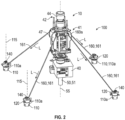
U.S. Patent No. 9,359,852 Figures 1 and2 , an embodiment of anoffshore system 10 for interfacing with awellbore 20. In this embodiment,system 10 includes a floatingoffshore vessel 30 at the sea surface 11, ahorizontal production tree 40 releasably connected to awellhead 50 disposed at an upper end of aprimary conductor 51 extending into thewellbore 20, a subsea blowout preventer (BOP) 41 releasably connected toproduction tree 40, and a lower marine riser package (LMRP) 42 releasably connected toBOP 41.Tree 40,BOP 41, and LMRP 42 are vertically arranged or stacked one-above-the-other, and are generally coaxially aligned withwellhead 50. Wellhead 50 has acentral axis 55 and extends vertically upward fromwellbore 20 above thesea floor 12. InFigure 1 of the '852 patent,system 10 is shown configured for completion operations, and thus, includestree 40, however, for drilling operations,tree 40 may not be included. - As best shown in
Figure 1 of the '852 patent,vessel 30 is equipped with aderrick 31 that supports a hoist (not shown). In this embodiment,vessel 30 is a semi-submersible offshore platform, however, in general, the vessel (e.g., vessel 30) can be any type of floating offshore drilling vessel including, without limitation, a moored structure (e.g., a semi-submersible platform), a dynamically positioned vessel (e.g., a drill ship), a tension leg platform, etc. A drilling riser 43 (not shown inFigure 2 of the '852 patent) extends subsea fromvessel 30 to LMRP 42. During drilling operations,riser 43 takes mud returns tovessel 30. Downhole operations are carried out by a tool connected to the lower end of the tubular string (e.g., drillstring) that is supported byderrick 31 and extends fromvessel 30 throughriser 43, LMRP 42, andBOP 41, andtree 40 intowellbore 20. In this embodiment of the '852 patent,BOP 41 includes an outer rectangularprismatic frame 47. - Still referring to the '852 patent,
BOP 41 and LMRP 42 are configured to controllablyseal wellbore 20 and contain hydrocarbon fluids therein. Specifically,BOP 41 includes a plurality of axially stacked sets of opposed rams disposed withinframe 47. In general,BOP 41 can include any number and type of rams including, without limitation, opposed double blind shear rams or blades for severing the tubular string and sealing offwellbore 20 fromriser 43, opposed blind rams for sealing off wellbore 20 when no string/tubular extends throughBOP 41, opposed pipe rams for engaging the string/tubular and sealing the annulus around string/tubular, or combinations thereof. LMRP 42 includes an annular blowout preventer comprising an annular elastomeric sealing element that is mechanically squeezed radially inward to seal on a string/tubular extending throughLMRP 42 or seal off wellbore when no string/tubular extends throughLMRP 42. The upper end of LMRP 42 includes ariser flex joint 44 that allowsriser 43 to deflect and pivot angularly relative totree 40,BOP 41, and LMRP 42 while fluids flow therethrough. - During drilling, completion, production, and workover operations, cyclical loads due to riser vibrations (e.g., from surface vessel motions, wave actions, current-induced VIV, or combinations thereof) are applied to
BOP 41,wellhead 50, andprimary conductor 51 extending fromwellhead 50 into thesea floor 12. Such cyclical loads can induce fatigue. This may be of particular concern with subsea horizontal production tree architectures (e.g., system 10) due to the relatively large height and weight of the hardware secured to the wellhead proximal the mud line (i.e., tree, BOP, and LMRP). For example, in this embodiment, the hardware mounted towellhead 50 proximal thesea floor 12,production tree 40 andBOP 41 in particular, is relatively tall, and thus, presents a relatively large surface area for interacting with environmental loads such as subsea currents. These environmental loads can also contribute to the fatigue ofBOP 41,wellhead 50, andprimary conductor 51. If thewellhead 50 andprimary conductor 51 do not have sufficient fatigue resistance, the integrity of the subsea well may be compromised. Still further, an uncontrolled lateral movement of vessel 30 (e.g., an uncontrolled drive off or drift off of vessel 30) from the desired operating location generally overwellhead 50 can pullLMRP 42 laterally withriser 43, thereby inducing bending moments and associated stresses inBOP 41,wellhead 50, andconductor 51. Such induced bending moments and stresses can be increased further when the relatively tall and heavy combination oftree 40 andBOP 41 is in a slight angle relative to vertical. Accordingly, in this embodiment, atethering system 100 is provided to reinforceBOP 41,wellhead 50, andprimary conductor 51 by resisting lateral loads and bending moments applied thereto. As a result,system 100 offers the potential to enhance the strength and fatigue resistance ofBOP 41,wellhead 50, andconductor 51. - Referring again to
Figures 1 and2 , in this embodiment,tethering system 100 includes a plurality ofanchors 110, a plurality of piletop assemblies 120, and a plurality of flexible tension members 160. One piletop assembly 120 is mounted to the upper end of eachanchor 110, and one tension member 160 extends from each piletop assembly 120 to frame 47 ofBOP 41. As will be described in more detail below, each piletop assembly 120 includes atensioning system 140 that can apply tensile loads to the corresponding tension member 160. In this embodiment, eachtensioning system 140 is a winch, and thus, may also be referred to aswinch 140. Eachwinch 140 can pay in and pay out the corresponding tensioning member 160. - Each tension member 160 includes a first or
distal end 160a coupled to frame 47 ofBOP 41, and a tensioned span orportion 161 extending from the correspondingwinch 140 to end 160a. As best shown inFigure 1 , eachdistal end 160a is coupled to frame 47 ofBOP 41 at a height H measured vertically from thesea floor 12 and at a lateral distance D measured radially and horizontally fromcentral axis 55. In this embodiment, four uniformlycircumferentiallyspaced anchors 110 and associated tension members 160 are provided. In addition, in this embodiment, height H of eachend 160a is the same, lateral distances D to eachend 160a is the same. For most subsea applications, lateral distance D is preferably between 5.0 and 15.0 feet, and more preferably about 10.0 ft. However, it should be appreciated that lateral distance D may depend, at least in part, on the available connection points to theframe 47 ofBOP 41. As will be described in more detail below, each height H is preferably as high as possible but belowLMRP 42, and may depend on the available connection points alongframe 47 ofBOP 41. - As best shown in
Figure 1 , a tensile preload L is applied to each tensionedspan 161. With no external loads or moments applied toBOP 41, the actual tension in eachspan 161 is the same or substantially the same as the corresponding tensile preload L. However, it should be appreciated that when external loads and/or bending moments are applied toBOP 41, the actual tension in eachspan 161 can be greater than or less than the corresponding tensile preload L. -
Winches 140 are positioned proximal to thesea floor 12, and ends 160a are coupled to frame 47 ofBOP 41 abovewinches 140. Thus, eachspan 161 is oriented at an acute angle α measured upward from horizontal. Sinceportions 161 are in tension and oriented at acute angles α, the tensile preload L applied to frame 47 ofBOP 41 by eachspan 161 includes an outwardly oriented horizontal or lateral preload L1 and a downwardly oriented vertical preload Lv. Without being limited by this or any particular theory, the lateral preload L1 and the vertical preload Lv applied toBOP 41 by each tension member 160 are a function of the corresponding tensile load L and the angle α. For a given angle α, the lateral preload L1 and the vertical preload Lv increase as the tensile load L increases, and decrease as the tensile load L decreases. For a given tensile load L, the lateral preload L1 decreases and the vertical preload Lv increases as angle α increases, and the lateral preload L1 increases and the vertical preload Lv decreases as angle α decreases. For example, at an angle α of 45°, the lateral preload L1 and the vertical preload Lv are substantially the same; at an angle α above 45°, the lateral preload Ll is less than the vertical preload Lv; and at an angle α below 45°, the lateral preload Ll is greater than the vertical preload Lv. In embodiments described herein, angle α of eachspan 161 is preferably between 10° and 60°, and more preferably between 30° and 45°. - The lateral preloads L1 applied to frame 47 of
BOP 41 resist external lateral loads and bending moments applied to BOP 41 (e.g., from subsea currents,riser 43, etc.). To reinforce and stabilizeBOP 41,wellhead 50, andprimary conductor 51 without interfering with an emergency disconnection ofLMRP 42, each height H is preferably as high as possible but belowLMRP 42, and may depend on the available connection points alongframe 47 ofBOP 41. In this embodiment, ends 160a are coupled to frame 47 proximal the upper end ofBOP 41 and just belowLMRP 42. By tetheringframe 47 ofBOP 41 at this location,system 100 restricts and/or preventsBOP 41,tree 40,wellhead 50, andprimary conductor 51 from moving and bending laterally, thereby stabilizing such components, while simultaneously allowingLMRP 42 to be disconnected from BOP 41 (e.g., via emergency disconnect package) without any interference fromsystem 100. - Referring again to
Figures 1 and2 , the tensile preload L in eachspan 161 is preferably as low as possible but sufficient to pull out any slack, curve, and catenary in thecorresponding span 161. In other words, the tensile preload in L in eachspan 161 is preferably the lowest tension that results in thatspan 161 extending linearly from the correspondingwinch 140 to itsend 160a. It should be appreciated that such tensile loads L in tension members 160 restrict and/or prevent the initial movement and flexing ofBOP 41 at the onset of the application of an external loads and/or bending moments, while minimizing the tension in eachspan 161 before and after the application of the external loads and/or bending moments. The latter consequence minimizes the potential risk of inadvertent damage toBOP 41,tree 40, andLMRP 42 in the event one or more tension members 160 uncontrollably break. - In general, each tension member 160 can include any elongate flexible member suitable for subsea use and capable of withstanding the anticipated tensile loads (i.e., the tensile preload L as well as the tensile loads induced in
spans 161 via the application of external loads to BOP 41) without deforming or elongating. Examples of suitable devices for tension members 160 can include, without limitation, chain(s), wire rope, and Dyneema® rope available from DSM Dyneema LLC of Stanley, North Carolina USA. In this embodiment, each tension member 160 comprises Dyneema® rope, which is suitable for subsea use, requires the lowest tensile preload L to pull out any slack, curve, and catenary (~ 1.0 ton of tension), and is sufficiently strong to withstand the anticipated tensions. - Referring now to
Figures 3-6 , analternate tethering system 200 includes a plurality ofanchors 220, a plurality oftensioning systems 240, a plurality offlexible tension members 260. Atension member 260 is connected to the top of each of the plurality ofanchors 220 and extends from eachanchor 220 to atensioning system 240 mounted onframe 47 ofBOP 41. Eachtensioning system 240 includes a winch or spool 242 that can pay in and pay out thecorresponding tension member 260 and a gripping mechanism 244 to engage thetension member 260. A winch refers to a reel having sufficient tensioning capacity to apply to the tension member 260 a tensile preload L as discussed in the description ofFigure 1 . A spool refers to a reel having a tensioning capacity to apply at least a tension sufficient to avoid sagging of thetension member 260, but thetension member 260 may remain slack. A spool may, however, have a tensioning capacity larger than the tension required to prevent sagging and may have as much tensioning capacity as a winch. -
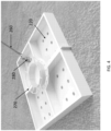
Figure 4 illustrates one embodiment of ananchor 220 to which atension member 260 is connected.Anchor 220 may be a driven piling, a clump weight, a suction piling, plate anchor, or any other structure used to affix a base to the sea floor. The top of theanchor 220 includes a connectingring 270, or other feature that provides a location for affixing an end of atension member 260.Tension member 260 includes areleasable connector 280 that allows an ROV to selectively engage and disengage thetension member 260 from theanchor 220. - The
gripping system 310 is coupled to theBOP frame 47 or be part of or mounted on theBOP 41.Figures 5 and 6 illustrate one embodiment of atensioning system 240 including aframe 300, grippingsystem 310,winch reel 320, andROV interface 330. Thetensioning system 240 may be removeably connected to theBOP frame 47 at connection points 340. An ROV, or other equipment, can be used to install eachtensioning system 240 onto theBOP frame 47 subsea by flying thetensioning system 240 into place and connecting it to the connection points 340. The ROV can then be used to rotatewinch reel 320 paying in or out tensioningmember 260 as needed. Once the tensioningmember 260 is properly installed, grippingsystem 310 can be activated to grip the tensioningmember 260 and maintain any tension in thetension member 260.Gripping system 310 can be any type of gripping system that can apply a fixing force to thetensioning member 260, such as a hydraulic slip system, a locking ring, or a brake mechanism. The hydraulic slip is used for paying in or outtension member 260. The hydraulic slip includes one or more hydraulic cylinders and a slip or gripper that may have a first configuration for paying in thetension member 260, applying to the tension member 260 a tensile preload L as discussed in the description ofFigure 1 , preventing pay out of theflexible tension member 260, and/or maintaining any tension in thetension member 260. The one or more hydraulic cylinders and the slip or gripper may have a second configuration for paying out thetension member 260. - Referring now to
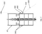
Figure 7 , analternative tensioning system 400 is shown that includes aframe 300 andgripping system 310 connected to aBOP frame 47 at connection points 340. Thewinch assembly 410 is located remote from thetensioning system 400, such as at the surface on the drilling or service vessel.Winch assembly 410 is used to apply pay in or out totension member 260 as needed to achieve the desired tension. Once thetension member 260 is properly tensioned, grippingsystem 310 can be activated to grip thetension member 260 and maintain any tension in thetension member 260. - While configurations have been shown and described, modifications thereof can be made by one skilled in the art without departing from the scope or teachings herein. The configurations described herein are exemplary only and are not limiting. Many variations and modifications of the systems, apparatus, and processes described herein are possible, as long as they are within the scope of the claims. For example, the relative dimensions of various parts, the materials from which the various parts are made, and other parameters can be varied. Accordingly, the scope of protection is not limited to the configurations described herein, but is only limited by the claims that follow, the scope of which shall include all equivalents of the subject matter of the claims. Unless expressly stated otherwise, the steps in a method claim may be performed in any order. The recitation of identifiers such as (a), (b), (c) or (1), (2), (3) before steps in a method claim are not intended to and do not specify a particular order to the steps, but rather are used to simplify subsequent reference to such steps.
Claims (6)
- A system (200) for tethering a subsea blowout preventer (BOP) (41), the system comprising:an anchor (220) disposed about the subsea BOP;a flexible tension member (260), wherein the flexible tension member has a first end including a releasable connector engaged to the anchor, wherein the flexible tension member extends horizontally and vertically from the first end to a second end to impart a lateral preload and a vertical preload to the subsea BOP; characterized in that the system comprises:a gripping system (244, 310) mounted on the subsea BOP, wherein the gripping system is configured to selectively engage the flexible tension member to prevent pay out of the flexible tension member; and further comprises a spool (242) coupled to the second end of the flexible tension member; anda hydraulic cylinder coupled to the gripping system, wherein actuation of the hydraulic cylinder causes paying in or out the flexible tension member.
- The system of claim 1 wherein the gripping system includes a slip.
- The system of claim 1 wherein the gripping system includes a locking ring or a brake mechanism.
- The system of claim 1 wherein the spool is located remotely from the subsea BOP, or wherein the spool is mounted to a releasable base connected to a connection point on the subsea BOP, or wherein the gripping system includes a slip.
- A method for tethering a subsea blowout preventer (BOP) (41) coupled to a subsea wellhead, characterized in that the subsea BOP includes a gripping system (244, 310) connected to a frame (47) of the subsea BOP, the method comprising:disposing an anchor (220) about the subsea BOP;extending a first end of a flexible tension member (260) horizontally and vertically;applying tension to the flexible tension member to impart a lateral preload and a vertical preload to the subsea BOP; andengaging the flexible tension member with the gripping system to maintain tension in the flexible tension member; and wherein applying tension to the flexible tension member comprises actuating a hydraulic cylinder coupled to the gripping system to cause paying in or out the flexible tension member.
- The method of claim 5 comprising preventing pay out of the flexible tension member using a locking ring or a brake mechanism.
Applications Claiming Priority (2)
| Application Number | Priority Date | Filing Date | Title |
|---|---|---|---|
| US201762454472P | 2017-02-03 | 2017-02-03 | |
| PCT/US2018/016821 WO2018144985A1 (en) | 2017-02-03 | 2018-02-05 | Systems and methods for tethering a subsea structure |
Publications (3)
| Publication Number | Publication Date |
|---|---|
| EP3577307A1 EP3577307A1 (en) | 2019-12-11 |
| EP3577307A4 EP3577307A4 (en) | 2020-11-18 |
| EP3577307B1 true EP3577307B1 (en) | 2025-04-09 |
Family
ID=63041189
Family Applications (1)
| Application Number | Title | Priority Date | Filing Date |
|---|---|---|---|
| EP18748787.1A Active EP3577307B1 (en) | 2017-02-03 | 2018-02-05 | Systems and methods for tethering a subsea structure |
Country Status (3)
| Country | Link |
|---|---|
| US (1) | US20200003025A1 (en) |
| EP (1) | EP3577307B1 (en) |
| WO (1) | WO2018144985A1 (en) |
Families Citing this family (11)
| Publication number | Priority date | Publication date | Assignee | Title |
|---|---|---|---|---|
| EP3577307B1 (en) | 2017-02-03 | 2025-04-09 | Trendsetter Vulcan Offshore Inc. | Systems and methods for tethering a subsea structure |
| GB2581072B (en) * | 2017-10-04 | 2021-10-27 | AME Pty Ltd | Improvements in or relating to subsea technology |
| US11549325B2 (en) | 2019-02-21 | 2023-01-10 | Trendsetter Vulcan Offshore, Inc. | Systems and methods for tethering subsea blow-out-preventers |
| GB2595991B (en) * | 2019-02-21 | 2022-08-24 | Trendsetter Vulcan Offshore Inc | Systems and methods for tethering subsea blow-out-preventers |
| NO347287B1 (en) * | 2019-09-13 | 2023-08-21 | Subseadesign As | A thether line for use in wellhead load relief applications for subsea wells |
| US20220402577A1 (en) * | 2019-11-07 | 2022-12-22 | Trendsetter Vulcan Offshore, Inc. | Systems and Methods for Tethering a Subsea Structure |
| NO20220645A1 (en) * | 2019-11-07 | 2022-06-03 | Aker Solutions As | Subsea wellhead systems and methods |
| WO2021094580A1 (en) * | 2019-11-13 | 2021-05-20 | Fmc Kongsberg Subsea As | A module, a system and a method for daisy chaining of satellite wells |
| US11028663B1 (en) * | 2019-11-18 | 2021-06-08 | Trendsetter Engineering, Inc. | Process and apparatus for installing a payload onto a subsea structure |
| GB202020531D0 (en) * | 2020-12-23 | 2021-02-03 | Tla Subsea Ltd | Apparatus, system and method for tethering a subsea assembly |
| CN113718754A (en) * | 2021-06-18 | 2021-11-30 | 海洋石油工程股份有限公司 | Tension balancing system arranged at bottom of vertical pipe |
Citations (11)
| Publication number | Priority date | Publication date | Assignee | Title |
|---|---|---|---|---|
| GB2257405A (en) | 1991-06-27 | 1993-01-13 | Bechtel Ltd | Tether deployment system |
| US5788417A (en) | 1995-03-03 | 1998-08-04 | American Oilfield Divers, Inc. | Offshore well stabilization apparatus and method |
| US5845893A (en) | 1997-03-14 | 1998-12-08 | Bardex Engineering, Inc. | Underwater self-aligning fairlead latch device for mooring a structure at sea |
| US20110107953A1 (en) | 2009-10-16 | 2011-05-12 | Jaehnig Jens | Floating Platform with Improved Anchoring |
| WO2013076461A1 (en) | 2011-11-22 | 2013-05-30 | Subsea 7 Limited | Tensioning and connector systems for tethers |
| WO2014194315A2 (en) | 2013-05-31 | 2014-12-04 | Bp Corporation North America Inc. | Systems and methods for pulling subsea structures |
| WO2014210026A2 (en) | 2013-06-24 | 2014-12-31 | Bp Corporation North America, Inc. | Systems and methods for tethering subsea blowout preventers to enhance the strength and fatigue resistance of subsea wellheads and primary conductors |
| WO2016118019A1 (en) | 2015-01-20 | 2016-07-28 | Statoil Petroleum As | Subsea wellhead assembly |
| WO2017139749A1 (en) | 2016-02-12 | 2017-08-17 | O'rourke Charlie | Rotary chain jack that maintains tension in a mooring line/chain |
| WO2017205430A1 (en) | 2016-05-23 | 2017-11-30 | O'rourke Charlie | Rotatable chain stopper |
| WO2018144985A1 (en) | 2017-02-03 | 2018-08-09 | Trendsetter Vulcan Offshore, Inc. | Systems and methods for tethering a subsea structure |
Family Cites Families (5)
| Publication number | Priority date | Publication date | Assignee | Title |
|---|---|---|---|---|
| US20100294505A1 (en) * | 2007-10-22 | 2010-11-25 | Andrea Sbordone | System and method for forming connections with a compliant guide |
| US9341025B2 (en) * | 2011-10-18 | 2016-05-17 | Total Sa | Floating offshore facility and a method for drilling a well |
| US9879396B2 (en) * | 2013-06-24 | 2018-01-30 | Trendsetter Vulcan Offshore, Inc. | Systems and methods for tethering subsea structure mounted on a wellhead |
| WO2014210035A2 (en) * | 2013-06-24 | 2014-12-31 | Bp Corporation North America, Inc. | Systems and methods for tethering subsea wellheads to enhance the fatigue resistance of subsea wellheads and primary conductors |
| US9074447B1 (en) * | 2014-01-15 | 2015-07-07 | Trendsetter Engineering, Inc. | Method and system for protecting wellhead integrity |
-
2018
- 2018-02-05 EP EP18748787.1A patent/EP3577307B1/en active Active
- 2018-02-05 US US16/481,731 patent/US20200003025A1/en not_active Abandoned
- 2018-02-05 WO PCT/US2018/016821 patent/WO2018144985A1/en not_active Ceased
Patent Citations (11)
| Publication number | Priority date | Publication date | Assignee | Title |
|---|---|---|---|---|
| GB2257405A (en) | 1991-06-27 | 1993-01-13 | Bechtel Ltd | Tether deployment system |
| US5788417A (en) | 1995-03-03 | 1998-08-04 | American Oilfield Divers, Inc. | Offshore well stabilization apparatus and method |
| US5845893A (en) | 1997-03-14 | 1998-12-08 | Bardex Engineering, Inc. | Underwater self-aligning fairlead latch device for mooring a structure at sea |
| US20110107953A1 (en) | 2009-10-16 | 2011-05-12 | Jaehnig Jens | Floating Platform with Improved Anchoring |
| WO2013076461A1 (en) | 2011-11-22 | 2013-05-30 | Subsea 7 Limited | Tensioning and connector systems for tethers |
| WO2014194315A2 (en) | 2013-05-31 | 2014-12-04 | Bp Corporation North America Inc. | Systems and methods for pulling subsea structures |
| WO2014210026A2 (en) | 2013-06-24 | 2014-12-31 | Bp Corporation North America, Inc. | Systems and methods for tethering subsea blowout preventers to enhance the strength and fatigue resistance of subsea wellheads and primary conductors |
| WO2016118019A1 (en) | 2015-01-20 | 2016-07-28 | Statoil Petroleum As | Subsea wellhead assembly |
| WO2017139749A1 (en) | 2016-02-12 | 2017-08-17 | O'rourke Charlie | Rotary chain jack that maintains tension in a mooring line/chain |
| WO2017205430A1 (en) | 2016-05-23 | 2017-11-30 | O'rourke Charlie | Rotatable chain stopper |
| WO2018144985A1 (en) | 2017-02-03 | 2018-08-09 | Trendsetter Vulcan Offshore, Inc. | Systems and methods for tethering a subsea structure |
Non-Patent Citations (5)
| Title |
|---|
| ASGEIR DAHL LIEN LIEN: "Methods to Improve Subsea Wellhead Fatigue Life (thesis)", NORWEGIAN UNIVERSITY OF SCIENCE AND TECHNOLOGY, 17 December 2009 (2009-12-17), Norwegian University of Science and Technology , pages FP - 42, XP055598118 |
| D10 - MARITIME REPORTER AND ENGINEERING NEWS- 1 SEPTEMBER 1985 |
| D8: "Mooring System Engineering for Offshore Structures", 4 June 2019, GULF PROFESSIONAL PUBLISHING, ISBN: 978-0-12-818551-3, article KAI-TUNG MA, YONG LUO, THOMAS KWAN, YONGYAN WU: "Chapter 10 - Hardware—on-vessel equipment", pages: 199 - 213, XP009565681, DOI: 10.1016/B978-0-12-818551-3.00010-7 |
| D9 - MOORING SYSTEMS FOR OFFSHORE FLOATING INSTALLATIONS, Trends & Technology, from Offshore Magazine - dated October 2013 |
| WU YONGYAN, WANG TAO, MA KAI-TUNG, HEYL CASPAR, GARRITY ROBERT, SHELTON JOHN: "Mooring Tensioning Systems for Offshore Platforms: Design, Installation, and Operating Considerations", DELMAR SYSTEMS, OTC, 30 April 2018 (2018-04-30) - 2018-05-03, XP093358631, DOI: 10.4043/28720-MS |
Also Published As
| Publication number | Publication date |
|---|---|
| US20200003025A1 (en) | 2020-01-02 |
| WO2018144985A1 (en) | 2018-08-09 |
| BR112019015560A2 (en) | 2020-03-17 |
| EP3577307A1 (en) | 2019-12-11 |
| EP3577307A4 (en) | 2020-11-18 |
Similar Documents
| Publication | Publication Date | Title |
|---|---|---|
| EP3577307B1 (en) | Systems and methods for tethering a subsea structure | |
| US9359852B2 (en) | Systems and methods for tethering subsea blowout preventers to enhance the strength and fatigue resistance of subsea wellheads and primary conductors | |
| US10577768B2 (en) | Systems and methods for tethering subsea structure mounted on a wellhead | |
| US20140374116A1 (en) | Systems and Methods for Tethering Subsea Wellheads to Enhance the Fatigue Resistance of Subsea Wellheads and Primary Conductors | |
| US7658228B2 (en) | High pressure system | |
| US8573307B2 (en) | High pressure sleeve for dual bore HP riser | |
| US9488024B2 (en) | Annulus cementing tool for subsea abandonment operation | |
| US9260931B2 (en) | Riser breakaway connection and intervention coupling device | |
| US9284806B2 (en) | Systems and methods for pulling subsea structures | |
| US9074447B1 (en) | Method and system for protecting wellhead integrity | |
| US20140374113A1 (en) | Systems and Methods for Bracing Subsea Wellheads to Enhance the Fatigue Resistance of Subsea Wellheads and Primary Conductors | |
| EP1963615B1 (en) | Dual-bop and common riser system | |
| US20130327534A1 (en) | Light Well Intervention Umbilical and Flying Lead Management System and Related Methods | |
| US20230399913A1 (en) | Apparatus and method for tubing hanger installation | |
| CN103328756A (en) | Method, system and apparatus for deployment of umbilicals in subsea well operations | |
| US10428610B2 (en) | Passively motion compensated tubing hanger running tool assembly | |
| US20150152695A1 (en) | Adjustable Riser Suspension System | |
| US20180171728A1 (en) | Combination well control/string release tool | |
| GB2412130A (en) | Arrangement and method for integrating a high pressure riser sleeve within a low pressure riser | |
| BR112019015560B1 (en) | SYSTEM AND METHOD FOR ATTACHING AN SUBMARINE ERUPTION PREVENTOR |
Legal Events
| Date | Code | Title | Description |
|---|---|---|---|
| STAA | Information on the status of an ep patent application or granted ep patent |
Free format text: STATUS: THE INTERNATIONAL PUBLICATION HAS BEEN MADE |
|
| PUAI | Public reference made under article 153(3) epc to a published international application that has entered the european phase |
Free format text: ORIGINAL CODE: 0009012 |
|
| STAA | Information on the status of an ep patent application or granted ep patent |
Free format text: STATUS: REQUEST FOR EXAMINATION WAS MADE |
|
| 17P | Request for examination filed |
Effective date: 20190903 |
|
| AK | Designated contracting states |
Kind code of ref document: A1 Designated state(s): AL AT BE BG CH CY CZ DE DK EE ES FI FR GB GR HR HU IE IS IT LI LT LU LV MC MK MT NL NO PL PT RO RS SE SI SK SM TR |
|
| AX | Request for extension of the european patent |
Extension state: BA ME |
|
| DAV | Request for validation of the european patent (deleted) | ||
| DAX | Request for extension of the european patent (deleted) | ||
| STAA | Information on the status of an ep patent application or granted ep patent |
Free format text: STATUS: EXAMINATION IS IN PROGRESS |
|
| A4 | Supplementary search report drawn up and despatched |
Effective date: 20201020 |
|
| RIC1 | Information provided on ipc code assigned before grant |
Ipc: E21B 29/10 20060101ALI20201014BHEP Ipc: E21B 41/00 20060101ALI20201014BHEP Ipc: E21B 33/064 20060101ALI20201014BHEP Ipc: E21B 41/10 20060101ALI20201014BHEP Ipc: E21B 19/08 20060101ALI20201014BHEP Ipc: E21B 19/02 20060101AFI20201014BHEP Ipc: E21B 33/035 20060101ALI20201014BHEP |
|
| 17Q | First examination report despatched |
Effective date: 20201110 |
|
| GRAP | Despatch of communication of intention to grant a patent |
Free format text: ORIGINAL CODE: EPIDOSNIGR1 |
|
| STAA | Information on the status of an ep patent application or granted ep patent |
Free format text: STATUS: GRANT OF PATENT IS INTENDED |
|
| INTG | Intention to grant announced |
Effective date: 20240319 |
|
| RIN1 | Information on inventor provided before grant (corrected) |
Inventor name: MAHER, JAMES V. |
|
| GRAJ | Information related to disapproval of communication of intention to grant by the applicant or resumption of examination proceedings by the epo deleted |
Free format text: ORIGINAL CODE: EPIDOSDIGR1 |
|
| STAA | Information on the status of an ep patent application or granted ep patent |
Free format text: STATUS: EXAMINATION IS IN PROGRESS |
|
| INTC | Intention to grant announced (deleted) | ||
| GRAP | Despatch of communication of intention to grant a patent |
Free format text: ORIGINAL CODE: EPIDOSNIGR1 |
|
| STAA | Information on the status of an ep patent application or granted ep patent |
Free format text: STATUS: GRANT OF PATENT IS INTENDED |
|
| INTG | Intention to grant announced |
Effective date: 20240920 |
|
| GRAS | Grant fee paid |
Free format text: ORIGINAL CODE: EPIDOSNIGR3 |
|
| GRAA | (expected) grant |
Free format text: ORIGINAL CODE: 0009210 |
|
| STAA | Information on the status of an ep patent application or granted ep patent |
Free format text: STATUS: THE PATENT HAS BEEN GRANTED |
|
| AK | Designated contracting states |
Kind code of ref document: B1 Designated state(s): AL AT BE BG CH CY CZ DE DK EE ES FI FR GB GR HR HU IE IS IT LI LT LU LV MC MK MT NL NO PL PT RO RS SE SI SK SM TR |
|
| REG | Reference to a national code |
Ref country code: GB Ref legal event code: FG4D |
|
| REG | Reference to a national code |
Ref country code: CH Ref legal event code: EP |
|
| REG | Reference to a national code |
Ref country code: DE Ref legal event code: R096 Ref document number: 602018080954 Country of ref document: DE |
|
| REG | Reference to a national code |
Ref country code: IE Ref legal event code: FG4D |
|
| REG | Reference to a national code |
Ref country code: NL Ref legal event code: MP Effective date: 20250409 |
|
| PG25 | Lapsed in a contracting state [announced via postgrant information from national office to epo] |
Ref country code: NL Free format text: LAPSE BECAUSE OF FAILURE TO SUBMIT A TRANSLATION OF THE DESCRIPTION OR TO PAY THE FEE WITHIN THE PRESCRIBED TIME-LIMIT Effective date: 20250409 |
|
| REG | Reference to a national code |
Ref country code: AT Ref legal event code: MK05 Ref document number: 1783661 Country of ref document: AT Kind code of ref document: T Effective date: 20250409 |
|
| PG25 | Lapsed in a contracting state [announced via postgrant information from national office to epo] |
Ref country code: PT Free format text: LAPSE BECAUSE OF FAILURE TO SUBMIT A TRANSLATION OF THE DESCRIPTION OR TO PAY THE FEE WITHIN THE PRESCRIBED TIME-LIMIT Effective date: 20250811 Ref country code: ES Free format text: LAPSE BECAUSE OF FAILURE TO SUBMIT A TRANSLATION OF THE DESCRIPTION OR TO PAY THE FEE WITHIN THE PRESCRIBED TIME-LIMIT Effective date: 20250409 Ref country code: FI Free format text: LAPSE BECAUSE OF FAILURE TO SUBMIT A TRANSLATION OF THE DESCRIPTION OR TO PAY THE FEE WITHIN THE PRESCRIBED TIME-LIMIT Effective date: 20250409 |
|
| REG | Reference to a national code |
Ref country code: LT Ref legal event code: MG9D |
|
| PG25 | Lapsed in a contracting state [announced via postgrant information from national office to epo] |
Ref country code: GR Free format text: LAPSE BECAUSE OF FAILURE TO SUBMIT A TRANSLATION OF THE DESCRIPTION OR TO PAY THE FEE WITHIN THE PRESCRIBED TIME-LIMIT Effective date: 20250710 |
|
| PG25 | Lapsed in a contracting state [announced via postgrant information from national office to epo] |
Ref country code: PL Free format text: LAPSE BECAUSE OF FAILURE TO SUBMIT A TRANSLATION OF THE DESCRIPTION OR TO PAY THE FEE WITHIN THE PRESCRIBED TIME-LIMIT Effective date: 20250409 |
|
| PG25 | Lapsed in a contracting state [announced via postgrant information from national office to epo] |
Ref country code: BG Free format text: LAPSE BECAUSE OF FAILURE TO SUBMIT A TRANSLATION OF THE DESCRIPTION OR TO PAY THE FEE WITHIN THE PRESCRIBED TIME-LIMIT Effective date: 20250409 |
|
| PG25 | Lapsed in a contracting state [announced via postgrant information from national office to epo] |
Ref country code: HR Free format text: LAPSE BECAUSE OF FAILURE TO SUBMIT A TRANSLATION OF THE DESCRIPTION OR TO PAY THE FEE WITHIN THE PRESCRIBED TIME-LIMIT Effective date: 20250409 |
|
| PG25 | Lapsed in a contracting state [announced via postgrant information from national office to epo] |
Ref country code: AT Free format text: LAPSE BECAUSE OF FAILURE TO SUBMIT A TRANSLATION OF THE DESCRIPTION OR TO PAY THE FEE WITHIN THE PRESCRIBED TIME-LIMIT Effective date: 20250409 |
|
| PG25 | Lapsed in a contracting state [announced via postgrant information from national office to epo] |
Ref country code: RS Free format text: LAPSE BECAUSE OF FAILURE TO SUBMIT A TRANSLATION OF THE DESCRIPTION OR TO PAY THE FEE WITHIN THE PRESCRIBED TIME-LIMIT Effective date: 20250709 |
|
| PG25 | Lapsed in a contracting state [announced via postgrant information from national office to epo] |
Ref country code: IS Free format text: LAPSE BECAUSE OF FAILURE TO SUBMIT A TRANSLATION OF THE DESCRIPTION OR TO PAY THE FEE WITHIN THE PRESCRIBED TIME-LIMIT Effective date: 20250809 |
|
| PG25 | Lapsed in a contracting state [announced via postgrant information from national office to epo] |
Ref country code: LV Free format text: LAPSE BECAUSE OF FAILURE TO SUBMIT A TRANSLATION OF THE DESCRIPTION OR TO PAY THE FEE WITHIN THE PRESCRIBED TIME-LIMIT Effective date: 20250409 |
|
| REG | Reference to a national code |
Ref country code: DE Ref legal event code: R026 Ref document number: 602018080954 Country of ref document: DE |
|
| PG25 | Lapsed in a contracting state [announced via postgrant information from national office to epo] |
Ref country code: SM Free format text: LAPSE BECAUSE OF FAILURE TO SUBMIT A TRANSLATION OF THE DESCRIPTION OR TO PAY THE FEE WITHIN THE PRESCRIBED TIME-LIMIT Effective date: 20250409 Ref country code: DK Free format text: LAPSE BECAUSE OF FAILURE TO SUBMIT A TRANSLATION OF THE DESCRIPTION OR TO PAY THE FEE WITHIN THE PRESCRIBED TIME-LIMIT Effective date: 20250409 |
|
| PLBI | Opposition filed |
Free format text: ORIGINAL CODE: 0009260 |
|
| PG25 | Lapsed in a contracting state [announced via postgrant information from national office to epo] |
Ref country code: CZ Free format text: LAPSE BECAUSE OF FAILURE TO SUBMIT A TRANSLATION OF THE DESCRIPTION OR TO PAY THE FEE WITHIN THE PRESCRIBED TIME-LIMIT Effective date: 20250409 |
|
| PLAX | Notice of opposition and request to file observation + time limit sent |
Free format text: ORIGINAL CODE: EPIDOSNOBS2 |
|
| REG | Reference to a national code |
Ref country code: CH Ref legal event code: L10 Free format text: ST27 STATUS EVENT CODE: U-0-0-L10-L00 (AS PROVIDED BY THE NATIONAL OFFICE) Effective date: 20260121 |
|
| PG25 | Lapsed in a contracting state [announced via postgrant information from national office to epo] |
Ref country code: EE Free format text: LAPSE BECAUSE OF FAILURE TO SUBMIT A TRANSLATION OF THE DESCRIPTION OR TO PAY THE FEE WITHIN THE PRESCRIBED TIME-LIMIT Effective date: 20250409 |
|
| PG25 | Lapsed in a contracting state [announced via postgrant information from national office to epo] |
Ref country code: RO Free format text: LAPSE BECAUSE OF FAILURE TO SUBMIT A TRANSLATION OF THE DESCRIPTION OR TO PAY THE FEE WITHIN THE PRESCRIBED TIME-LIMIT Effective date: 20250409 Ref country code: SK Free format text: LAPSE BECAUSE OF FAILURE TO SUBMIT A TRANSLATION OF THE DESCRIPTION OR TO PAY THE FEE WITHIN THE PRESCRIBED TIME-LIMIT Effective date: 20250409 |
|
| PG25 | Lapsed in a contracting state [announced via postgrant information from national office to epo] |
Ref country code: IT Free format text: LAPSE BECAUSE OF FAILURE TO SUBMIT A TRANSLATION OF THE DESCRIPTION OR TO PAY THE FEE WITHIN THE PRESCRIBED TIME-LIMIT Effective date: 20250409 |
|
| 26 | Opposition filed |
Opponent name: EQUINOR ENERGY AS Effective date: 20260109 |