EP3577281B1 - Pipe layer attachment for an excavator - Google Patents
Pipe layer attachment for an excavator Download PDFInfo
- Publication number
- EP3577281B1 EP3577281B1 EP17895333.7A EP17895333A EP3577281B1 EP 3577281 B1 EP3577281 B1 EP 3577281B1 EP 17895333 A EP17895333 A EP 17895333A EP 3577281 B1 EP3577281 B1 EP 3577281B1
- Authority
- EP
- European Patent Office
- Prior art keywords
- boom
- excavator
- pipe layer
- attachment
- arm
- Prior art date
- Legal status (The legal status is an assumption and is not a legal conclusion. Google has not performed a legal analysis and makes no representation as to the accuracy of the status listed.)
- Active
Links
Images

Classifications
-
- E—FIXED CONSTRUCTIONS
- E02—HYDRAULIC ENGINEERING; FOUNDATIONS; SOIL SHIFTING
- E02F—DREDGING; SOIL-SHIFTING
- E02F3/00—Dredgers; Soil-shifting machines
- E02F3/04—Dredgers; Soil-shifting machines mechanically-driven
- E02F3/96—Dredgers; Soil-shifting machines mechanically-driven with arrangements for alternate or simultaneous use of different digging elements
-
- F—MECHANICAL ENGINEERING; LIGHTING; HEATING; WEAPONS; BLASTING
- F16—ENGINEERING ELEMENTS AND UNITS; GENERAL MEASURES FOR PRODUCING AND MAINTAINING EFFECTIVE FUNCTIONING OF MACHINES OR INSTALLATIONS; THERMAL INSULATION IN GENERAL
- F16L—PIPES; JOINTS OR FITTINGS FOR PIPES; SUPPORTS FOR PIPES, CABLES OR PROTECTIVE TUBING; MEANS FOR THERMAL INSULATION IN GENERAL
- F16L1/00—Laying or reclaiming pipes; Repairing or joining pipes on or under water
- F16L1/024—Laying or reclaiming pipes on land, e.g. above the ground
- F16L1/028—Laying or reclaiming pipes on land, e.g. above the ground in the ground
-
- B—PERFORMING OPERATIONS; TRANSPORTING
- B66—HOISTING; LIFTING; HAULING
- B66C—CRANES; LOAD-ENGAGING ELEMENTS OR DEVICES FOR CRANES, CAPSTANS, WINCHES, OR TACKLES
- B66C13/00—Other constructional features or details
- B66C13/12—Arrangements of means for transmitting pneumatic, hydraulic, or electric power to movable parts of devices
- B66C13/14—Arrangements of means for transmitting pneumatic, hydraulic, or electric power to movable parts of devices to load-engaging elements or motors associated therewith
-
- B—PERFORMING OPERATIONS; TRANSPORTING
- B66—HOISTING; LIFTING; HAULING
- B66C—CRANES; LOAD-ENGAGING ELEMENTS OR DEVICES FOR CRANES, CAPSTANS, WINCHES, OR TACKLES
- B66C23/00—Cranes comprising essentially a beam, boom, or triangular structure acting as a cantilever and mounted for translatory of swinging movements in vertical or horizontal planes or a combination of such movements, e.g. jib-cranes, derricks, tower cranes
- B66C23/18—Cranes comprising essentially a beam, boom, or triangular structure acting as a cantilever and mounted for translatory of swinging movements in vertical or horizontal planes or a combination of such movements, e.g. jib-cranes, derricks, tower cranes specially adapted for use in particular purposes
- B66C23/36—Cranes comprising essentially a beam, boom, or triangular structure acting as a cantilever and mounted for translatory of swinging movements in vertical or horizontal planes or a combination of such movements, e.g. jib-cranes, derricks, tower cranes specially adapted for use in particular purposes mounted on road or rail vehicles; Manually-movable jib-cranes for use in workshops; Floating cranes
-
- B—PERFORMING OPERATIONS; TRANSPORTING
- B66—HOISTING; LIFTING; HAULING
- B66C—CRANES; LOAD-ENGAGING ELEMENTS OR DEVICES FOR CRANES, CAPSTANS, WINCHES, OR TACKLES
- B66C23/00—Cranes comprising essentially a beam, boom, or triangular structure acting as a cantilever and mounted for translatory of swinging movements in vertical or horizontal planes or a combination of such movements, e.g. jib-cranes, derricks, tower cranes
- B66C23/62—Constructional features or details
- B66C23/64—Jibs
-
- E—FIXED CONSTRUCTIONS
- E02—HYDRAULIC ENGINEERING; FOUNDATIONS; SOIL SHIFTING
- E02F—DREDGING; SOIL-SHIFTING
- E02F3/00—Dredgers; Soil-shifting machines
- E02F3/04—Dredgers; Soil-shifting machines mechanically-driven
- E02F3/28—Dredgers; Soil-shifting machines mechanically-driven with digging tools mounted on a dipper- or bucket-arm, i.e. there is either one arm or a pair of arms, e.g. dippers, buckets
- E02F3/36—Component parts
- E02F3/38—Cantilever beams, i.e. booms;, e.g. manufacturing processes, forms, geometry or materials used for booms; Dipper-arms, e.g. manufacturing processes, forms, geometry or materials used for dipper-arms; Bucket-arms
-
- F—MECHANICAL ENGINEERING; LIGHTING; HEATING; WEAPONS; BLASTING
- F16—ENGINEERING ELEMENTS AND UNITS; GENERAL MEASURES FOR PRODUCING AND MAINTAINING EFFECTIVE FUNCTIONING OF MACHINES OR INSTALLATIONS; THERMAL INSULATION IN GENERAL
- F16L—PIPES; JOINTS OR FITTINGS FOR PIPES; SUPPORTS FOR PIPES, CABLES OR PROTECTIVE TUBING; MEANS FOR THERMAL INSULATION IN GENERAL
- F16L1/00—Laying or reclaiming pipes; Repairing or joining pipes on or under water
- F16L1/024—Laying or reclaiming pipes on land, e.g. above the ground
- F16L1/06—Accessories therefor, e.g. anchors
- F16L1/065—Accessories therefor, e.g. anchors fixed on or to vehicles
-
- E—FIXED CONSTRUCTIONS
- E02—HYDRAULIC ENGINEERING; FOUNDATIONS; SOIL SHIFTING
- E02F—DREDGING; SOIL-SHIFTING
- E02F7/00—Equipment for conveying or separating excavated material
- E02F7/04—Loading devices mounted on a dredger or an excavator hopper dredgers, also equipment for unloading the hopper
Definitions
- the present disclosure relates to construction equipment. More particularly, the present disclosure relates to construction equipment configured for use in laying pipe or similar tasks involving lifting.
- Oil and gas pipeline contractors require construction equipment that provides maneuverability and multiple pipe placement possibilities.
- Examples of construction equipment include excavators and pipe layers.
- Excavators must traverse across difficult terrain as they are used for site preparation and to form trenches.
- Rotatable excavators allow the bucket to position itself 360 degrees around the undercarriage.
- Some pipe layers have fixed non-rotatable booms and are used to lift and place pipe sections within the preformed trench. Pipe layers are designed move laterally along the trench to place pipe sections adjacent one another.
- equipment for laying pipe is currently available as a dedicated pipe layer.
- dedicated pipe layers can be designed with booms having a length of about nine meters or more, while maintaining stability to lift 5,000 kgs or more.
- pipe laying equipment is sometimes provided in the form of a side-boom attachment.
- Construction vehicles such as back hoes or wheel loaders have been fit with a side-boom attachment pipe laying equipment.
- These side-boom attachments generally have booms that are about 5 meters or less in length to limit the potential for tip over. These shorter booms and resulting shorter reach limit the effectiveness of these solutions.
- Embodiments of the present disclosure include a pipe layer attachment for an excavator.
- the pipe layer attachment includes a winch configured to wind and unwind a cable having a hook attached thereto.
- the pipe layer attachment also includes a pipe layer boom configured to mount onto a boom of the excavator as a cantilever with the pipe layer boom extending beyond an end of the boom.
- the pipe layer boom is configured to be connected to an arm attachment pin connection of the boom and an arm cylinder pin connection of the boom.
- the pipe layers include an undercarriage, an upper structure rotatable relative to the undercarriage, and a boom pivotably attached to the upper structure, the boom comprising a first pin connection adjacent to a distal end of the boom opposite the upper structure, and a second pin connection along the boom.
- a pipe layer boom is attached to the boom at the first pin connection and the second pin connection with the pipe layer boom cantilevered beyond the distal end of the boom.
- the pipe layer boom supports a sheave at an end thereof, and a winch is configured to wind and unwind a cable passing over the sheave, the cable having a hook attached thereto.
- Yet additional embodiments provide methods of retrofitting an excavator having a boom pivotably attached to an upper structure, an arm mounted to a distal end of the boom at an arm attachment pin connection, a bucket attached to the arm, an arm cylinder mounted to the boom at an arm cylinder attachment pin connection, and a hydraulic fluid supply line attached to the arm cylinder.
- the methods include receiving the excavator with the bucket, arm, and arm cylinder removed.
- the method further comprises attaching a pipe layer boom to the boom at the arm attachment pin connection and at the arm cylinder attachment pin connection.
- the pipe layer boom is attached to the boom as a cantilever extending beyond the distal end of the boom.
- the pipe layer attachment 100 includes a pipe layer boom 102 and a lifting system 104.
- the pipe layer boom 102 has a first distal end 106 and a second distal end 108.
- An imaginary centerline C can pass through the pipe layer boom 102 from the first distal end 106 to the second distal end 108.
- the centerline C is non-linear.
- the pipe layer boom 102 has an extension 110 adjacent to the first distal end 106 and a base 112 adjacent to the second distal end 108.
- An obtuse angle ⁇ is formed on the centerline C where the extension 110 meets the base 112.
- the first distal end 106 of the pipe layer boom 102 can support a sheave 114 rotatably attached thereto.
- the pipe layer boom 102 includes two mounting points 116, 118.
- the mounting points 116, 118 are apertures configured to receive pins for creating joints.
- the first mounting point 116 is formed at the end of a linkage 120 pivotably attached to the extension 110 of the pipe layer boom 102 at a hinge joint 122.
- the linkage 120 can include a bracket 124 along the length thereof.
- the first mounting point can be fixed in relation to the centerline.
- the second mounting point 118 is an aperture near the second distal end 108 of the pipe layer boom 102. In other embodiments, the second mounting point 118 can be spaced from the second distal end 108. In other embodiments, the second mounting point 118 can be provided as part of bracket (not shown) attached to the base 112 of the pipe layer boom 102.
- the lifting system 104 facilitates lifting of a pipe section.
- the lifting system 104 shown in FIG. 1 includes a winch 130.
- the winch 130 is attached to the pipe layer boom 102.
- the winch 130 can be separate from the pipe layer boom 102.
- the winch 130 is a hydraulically driven winch.
- the winch 130 can be electric.
- the lifting system 104 can also include a cable 132 for being wound and unwound around the winch 130. As shown in the embodiment of FIG. 1 , the cable 132 passes over the sheave 114. A hook 134 attaches to the cable 132 to lift and lower objects, such as pipes, as the cable 132 is being wound or unwound. The hook 134 can attach to the bracket 124, which may form a loop, of the linkage 120 when storing or transporting the pipe layer attachment 100. As known in the art, a load moment indicator (LMI), such as a line rider 140, can be applied to the cable 132. The LMI can transmit wirelessly to a display to notify the operator if the load on the hook 134 approaches a weight limit setting.
- LMI load moment indicator
- the pipe layer attachment 100 is intended for retrofitting an excavator for use in laying pipe.
- an excavator 200 is shown that is suitable for conversion according to the present disclosure.
- the excavator 200 includes an undercarriage 202.
- the excavator 200 also includes an upper structure 204, such as a cab and engine room, capable of being rotated on top of the undercarriage 202.
- the excavator 200 further comprises a boom 206 pivotably mounted to the upper structure 204.
- An arm 208 is pivotably attached to the boom 206 by an arm attachment pin connection 210.
- a bucket 212 is pivotably attached to the arm 208 by a bucket attachment pin connection 214.
- a boom cylinder 216 is used to rotate the boom 206 relative to the upper structure 204.
- An arm cylinder 218 is used to rotate the arm 208 relative to the boom 206.
- the arm cylinder 218 is attached to the boom 206 at an arm cylinder attachment pin connection 220.
- the arm cylinder 218 is driven by fluid from a hydraulic fluid line 222.
- a bucket cylinder 224 is used to rotate the bucket 212 relative to the arm 208.
- FIG. 2B shows the excavator 200 in a form suitable for receiving the pipe layer attachment 100.
- the excavator 200 has retained the boom 206 with the arm attachment pin connection 210 and the arm cylinder attachment pin connection 220.
- the arm, bucket, arm cylinder, and bucket cylinder have all been removed.
- FIG. 2C shows the pipe layer attachment 100 mounted to the boom 206 of the excavator 200 and transforming the excavator into a rotating pipe layer.
- the first mounting point 116 of the pipe layer boom 102 is joined to the boom 206 of the excavator 200 with the arm attachment pin connection 210.
- the second mounting point 118 of the pipe layer boom 102 is joined to the boom 206 of the excavator 200 with the arm cylinder attachment pin connection 220.
- the pipe layer attachment 100 is fixed to the boom 206 and not pivotable with respect to the boom.
- pivoting the boom 206 relative to the upper structure 204 moves the pipe layer attachment 100 relative to the upper structure.
- operation of the winch 130 of the pipe layer attachment 100 is facilitated by connecting a hydraulic fluid line 223 to the winch.
- the hydraulic fluid line 223 may connect to auxiliary hydraulics incorporated into the excavator that allow for independent operation of the boom 206 and the winch 130.
- the pipe layer boom 102 When mounted on the boom 206, the pipe layer boom 102 is configured as a cantilever with the extension 110 reaching beyond the arm attachment pin connection 210 of the boom, extending the reach R of the hook 134 relative to the undercarriage 202.
- the reach R ranges from about four meters to about ten meters.
- the sheave 114 is positioned higher above the ground than the arm attachment pin connection 210, increasing the maximum height H of the hook 134. In one embodiment the maximum height ranges from about three and a half meters to about six meters.
- cantilever refers to the use of a generally rigid structural element, such as the pipe layer boom 102 in this embodiment, that has at least one distal end that is unsupported. In the embodiment shown, distal end 106 is unsupported, and the structural support is provided by attachment points 116 and 118.
- the pipe layer attachment 100 of the illustrated embodiment provides several advantages over alternative methods of using an excavator for laying pipe.
- the pipe layer attachment 100 makes use of the pre-existing arm attachment pin connection 210 and the pre-existing arm cylinder attachment pin connection 220 as attachment locations between the boom 206 of the excavator 200 and the pipe layer boom 102.
- Use of these preexisting connection points facilitates an easy and economical conversion process that does not require permanently modifying existing excavator components.
- the excavator 200 can be returned to its original functionality.
Landscapes
- Engineering & Computer Science (AREA)
- Mechanical Engineering (AREA)
- General Engineering & Computer Science (AREA)
- Mining & Mineral Resources (AREA)
- Civil Engineering (AREA)
- Structural Engineering (AREA)
- Life Sciences & Earth Sciences (AREA)
- Shovels (AREA)
- Soil Sciences (AREA)
- Environmental Sciences (AREA)
- Earth Drilling (AREA)
- Jib Cranes (AREA)
- Component Parts Of Construction Machinery (AREA)
Description
- The present disclosure relates to construction equipment. More particularly, the present disclosure relates to construction equipment configured for use in laying pipe or similar tasks involving lifting.
- Oil and gas pipeline contractors require construction equipment that provides maneuverability and multiple pipe placement possibilities. Examples of construction equipment include excavators and pipe layers. Excavators must traverse across difficult terrain as they are used for site preparation and to form trenches. Rotatable excavators allow the bucket to position itself 360 degrees around the undercarriage. Some pipe layers have fixed non-rotatable booms and are used to lift and place pipe sections within the preformed trench. Pipe layers are designed move laterally along the trench to place pipe sections adjacent one another.
- In one form, equipment for laying pipe is currently available as a dedicated pipe layer. By being designed with the expressly intended use of laying pipe, dedicated pipe layers can be designed with booms having a length of about nine meters or more, while maintaining stability to lift 5,000 kgs or more.
- A growing need exists for versatile machines that allow contractors to reduce equipment purchases and conserve resources. For example, pipe laying equipment is sometimes provided in the form of a side-boom attachment. Construction vehicles such as back hoes or wheel loaders have been fit with a side-boom attachment pipe laying equipment. These side-boom attachments generally have booms that are about 5 meters or less in length to limit the potential for tip over. These shorter booms and resulting shorter reach limit the effectiveness of these solutions.
- A need remains for improved equipment suitable for laying pipe that combines the benefits of a dedicated pipe layer with the benefits of an attachment. Documents
JPH0995965A JPS62268432A ITPC20120015A1 JPS637427A - Embodiments of the present disclosure include a pipe layer attachment for an excavator. The pipe layer attachment includes a winch configured to wind and unwind a cable having a hook attached thereto. The pipe layer attachment also includes a pipe layer boom configured to mount onto a boom of the excavator as a cantilever with the pipe layer boom extending beyond an end of the boom. The pipe layer boom is configured to be connected to an arm attachment pin connection of the boom and an arm cylinder pin connection of the boom.
- Other embodiments of the present disclosure include pipe layers. The pipe layers include an undercarriage, an upper structure rotatable relative to the undercarriage, and a boom pivotably attached to the upper structure, the boom comprising a first pin connection adjacent to a distal end of the boom opposite the upper structure, and a second pin connection along the boom. A pipe layer boom is attached to the boom at the first pin connection and the second pin connection with the pipe layer boom cantilevered beyond the distal end of the boom. The pipe layer boom supports a sheave at an end thereof, and a winch is configured to wind and unwind a cable passing over the sheave, the cable having a hook attached thereto.
- Yet additional embodiments provide methods of retrofitting an excavator having a boom pivotably attached to an upper structure, an arm mounted to a distal end of the boom at an arm attachment pin connection, a bucket attached to the arm, an arm cylinder mounted to the boom at an arm cylinder attachment pin connection, and a hydraulic fluid supply line attached to the arm cylinder. The methods include receiving the excavator with the bucket, arm, and arm cylinder removed. The method further comprises attaching a pipe layer boom to the boom at the arm attachment pin connection and at the arm cylinder attachment pin connection. The pipe layer boom is attached to the boom as a cantilever extending beyond the distal end of the boom.
- These and other aspects of the present disclosure will become apparent to those skilled in the art after a reading of the following description of the preferred embodiments, when considered in conjunction with the drawings. It should be understood that both the foregoing general description and the following detailed description are explanatory only and are not restrictive of the invention as claimed.
-
-
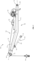
FIG. 1 shows a pipe layer attachment according to embodiments of the present disclosure. -
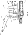
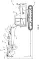
FIGs. 2A-2C show a process for retrofitting an excavator with a pipe layer attachment according to embodiments of the present disclosure. - Exemplary embodiments of this disclosure are described below and illustrated in the accompanying figures, in which like numerals refer to like parts throughout the several views. The embodiments described provide examples and should not be interpreted as limiting the scope of the invention. Other embodiments, and modifications and improvements of the described embodiments, will occur to those skilled in the art and all such other embodiments, modifications and improvements are within the scope of the present invention. Features from one embodiment or aspect can be combined with features from any other embodiment or aspect in any appropriate combination. For example, any individual or collective features of method aspects or embodiments can be applied to apparatus, product or component aspects or embodiments and vice versa.
- As shown in
FIG. 1 , apipe layer attachment 100 is shown. Thepipe layer attachment 100 includes apipe layer boom 102 and alifting system 104. Thepipe layer boom 102 has a firstdistal end 106 and a seconddistal end 108. An imaginary centerline C can pass through thepipe layer boom 102 from the firstdistal end 106 to the seconddistal end 108. In the illustrated embodiment, the centerline C is non-linear. In the present embodiment, thepipe layer boom 102 has anextension 110 adjacent to the firstdistal end 106 and abase 112 adjacent to the seconddistal end 108. An obtuse angle α is formed on the centerline C where theextension 110 meets thebase 112. - The first
distal end 106 of thepipe layer boom 102 can support asheave 114 rotatably attached thereto. - In the embodiment shown, the
pipe layer boom 102 includes twomounting points mounting points FIG. 1 , thefirst mounting point 116 is formed at the end of alinkage 120 pivotably attached to theextension 110 of thepipe layer boom 102 at ahinge joint 122. Thelinkage 120 can include abracket 124 along the length thereof. Instead of using thelinkage 120 that allows thefirst mounting point 116 to move relative to the centerline C, in other embodiments, the first mounting point can be fixed in relation to the centerline. - In the illustrated embodiment of
FIG. 1 , thesecond mounting point 118 is an aperture near the seconddistal end 108 of thepipe layer boom 102. In other embodiments, thesecond mounting point 118 can be spaced from the seconddistal end 108. In other embodiments, thesecond mounting point 118 can be provided as part of bracket (not shown) attached to thebase 112 of thepipe layer boom 102. - The
lifting system 104 facilitates lifting of a pipe section. Thelifting system 104 shown inFIG. 1 includes awinch 130. In one embodiment, thewinch 130 is attached to thepipe layer boom 102. In other embodiments, thewinch 130 can be separate from thepipe layer boom 102. In an embodiment, thewinch 130 is a hydraulically driven winch. In other embodiments, thewinch 130 can be electric. - The
lifting system 104 can also include acable 132 for being wound and unwound around thewinch 130. As shown in the embodiment ofFIG. 1 , thecable 132 passes over thesheave 114. Ahook 134 attaches to thecable 132 to lift and lower objects, such as pipes, as thecable 132 is being wound or unwound. Thehook 134 can attach to thebracket 124, which may form a loop, of thelinkage 120 when storing or transporting thepipe layer attachment 100. As known in the art, a load moment indicator (LMI), such as aline rider 140, can be applied to thecable 132. The LMI can transmit wirelessly to a display to notify the operator if the load on thehook 134 approaches a weight limit setting. - According to embodiments of the present disclosure, the
pipe layer attachment 100 is intended for retrofitting an excavator for use in laying pipe. Turning toFIG. 2A , anexcavator 200 is shown that is suitable for conversion according to the present disclosure. Theexcavator 200 includes anundercarriage 202. Theexcavator 200 also includes anupper structure 204, such as a cab and engine room, capable of being rotated on top of theundercarriage 202. Theexcavator 200 further comprises aboom 206 pivotably mounted to theupper structure 204. Anarm 208 is pivotably attached to theboom 206 by an armattachment pin connection 210. Abucket 212 is pivotably attached to thearm 208 by a bucketattachment pin connection 214. Aboom cylinder 216 is used to rotate theboom 206 relative to theupper structure 204. Anarm cylinder 218 is used to rotate thearm 208 relative to theboom 206. Thearm cylinder 218 is attached to theboom 206 at an arm cylinderattachment pin connection 220. In one embodiment, thearm cylinder 218 is driven by fluid from ahydraulic fluid line 222. Further, abucket cylinder 224 is used to rotate thebucket 212 relative to thearm 208. -
FIG. 2B shows theexcavator 200 in a form suitable for receiving thepipe layer attachment 100. As seen inFIG. 2B , theexcavator 200 has retained theboom 206 with the armattachment pin connection 210 and the arm cylinderattachment pin connection 220. The arm, bucket, arm cylinder, and bucket cylinder have all been removed. -
FIG. 2C shows thepipe layer attachment 100 mounted to theboom 206 of theexcavator 200 and transforming the excavator into a rotating pipe layer. Thefirst mounting point 116 of thepipe layer boom 102 is joined to theboom 206 of theexcavator 200 with the armattachment pin connection 210. Similarly, thesecond mounting point 118 of thepipe layer boom 102 is joined to theboom 206 of theexcavator 200 with the arm cylinderattachment pin connection 220. By providing thefirst mounting point 116 on thelinkage 120, the ability to adjust the relative positioning between thefirst mounting point 116 and thesecond mounting point 118 can increase the attachment tolerance between thepipe layer attachment 100 and theboom 206. In the present embodiment, thepipe layer attachment 100 is fixed to theboom 206 and not pivotable with respect to the boom. In the present embodiment, pivoting theboom 206 relative to theupper structure 204 moves thepipe layer attachment 100 relative to the upper structure. - According to one embodiment, operation of the
winch 130 of thepipe layer attachment 100 is facilitated by connecting ahydraulic fluid line 223 to the winch. Thehydraulic fluid line 223 may connect to auxiliary hydraulics incorporated into the excavator that allow for independent operation of theboom 206 and thewinch 130. - When mounted on the
boom 206, thepipe layer boom 102 is configured as a cantilever with theextension 110 reaching beyond the armattachment pin connection 210 of the boom, extending the reach R of thehook 134 relative to theundercarriage 202. In one embodiment, the reach R ranges from about four meters to about ten meters. Further, due to the shape of the centerline C in the illustrated embodiment, thesheave 114 is positioned higher above the ground than the armattachment pin connection 210, increasing the maximum height H of thehook 134. In one embodiment the maximum height ranges from about three and a half meters to about six meters. - As used herein, "cantilever" refers to the use of a generally rigid structural element, such as the
pipe layer boom 102 in this embodiment, that has at least one distal end that is unsupported. In the embodiment shown,distal end 106 is unsupported, and the structural support is provided byattachment points - The
pipe layer attachment 100 of the illustrated embodiment provides several advantages over alternative methods of using an excavator for laying pipe. Particularly, thepipe layer attachment 100 makes use of the pre-existing armattachment pin connection 210 and the pre-existing arm cylinderattachment pin connection 220 as attachment locations between theboom 206 of theexcavator 200 and thepipe layer boom 102. Use of these preexisting connection points facilitates an easy and economical conversion process that does not require permanently modifying existing excavator components. By avoiding permanent modifications to existing excavator components, theexcavator 200 can be returned to its original functionality.
Claims (13)
- A pipe layer attachment (100) for an excavator (200), comprising:an excavator undercarriage (202);an excavator upper structure (204) rotatable relative to the undercarriage;an excavator boom (206) pivotably mounted to the upper structure so that a distal end of the excavator boom is opposite the upper structure, the excavator boom including an excavator arm attachment p in connection (210) adjacent to the distal end and an excavator arm cylinder pin connection (220) along the excavator boom;an excavator boom cylinder (216) used to rotate the excavator boom relative to the upper structure;a pipe layer boom (102) mounted onto the excavator boom as a cantilever with the pipe layer boom provided with an extension (110) extending beyond the distal end of the excavator boom,the pipe layer boom (102) connected to the excavator arm attachment pin connection (210) of the excavator boom (206) and the excavator arm cylinder pin connection (220) of the excavator boom;the pipe layer boom (102) fixed to the excavator boom (206), whereby the pipe layer boom is not pivotable with respect to the excavator boom and so that pivoting the excavator boom relative to the upper structure (204) moves the pipe layer boom relative to the upper structure; anda winch (130) configured to wind and unwind a cable (132) having a hook (134) attached thereto.
- The pipe layer attachment (100) of claim 1, further comprising a linkage (120) pivotably attached to the pipe layer boom (102) and configured to be attached to the arm attachment pin connection (210) of the excavator boom (206).
- The pipe layer attachment (100) of claim 2, wherein the linkage (120) includes a bracket (124) on which the hook (134) can be engaged while transporting the excavator (200).
- The pipe layer attachment (100) of claim 1, wherein the pipe layer boom (102) comprises at least one mounting point (116, 118), the at least one mounting point is an aperture.
- The pipe layer attachment (100) of claim 1, wherein the pipe layer boom (102) comprises a base (112) and the extension (110), the extension forming an obtuse angle (α) with respect to the base.
- The pipe layer attachment (100) of claim 1, wherein the pipe layer boom (102) supports a sheave (114) at a distal end thereof.
- The pipe layer attachment (100) of claim 1, further comprising the cable (132), the hook (134) and a load moment indicator (140) for attachment to the cable.
- A method of retrofitting an excavator (200), wherein the excavator has an excavator boom (206) pivotably attached to an excavator upper structure (204) so that a distal end of the excavator boom is opposite the upper structure, an excavator boom cylinder (216) used to rotate the excavator boom relative to the upper structure, an excavator arm (208) mounted to the distal end of the excavator boom at an excavator arm attachment pin connection (210), an excavator bucket (212) attached to the arm, and an excavator arm cylinder (218) mounted to the excavator boom at an excavator arm cylinder attachment pin connection (220), the method comprising:receiving the excavator (200) with the excavator bucket (212), arm (208), and arm cylinder (218) removed; andattaching a pipe layer boom (102) to the excavator boom (206) at the excavator arm attachment pin connection (210) and at the excavator arm cylinder attachment pin connection (220)of the excavator boom so thatthe pipe layer boom (102) is mounted onto the excavator boom (206) as a cantilever;an extension (110) of the pipe layer boom extends beyond the distal end of the excavator boom;the pipe layer boom (102) is fixed to the excavator boom (206), whereby the pipe layer is not pivotable with respect to the excavator boom and so that pivoting the excavator boom relative to the upper structure (204) moves the pipe layer boom relative to the upper structure; andproviding a winch (130) configured to wind and unwind a cable (132) having a hook (134) attached thereto.
- The method of claim 8, wherein the pipe layer boom (102) supports a sheave (114) at a distal end thereof, the method further comprising passing a cable (132) from the winch (130) over the sheave.
- The method of claim 8, wherein attaching the pipe layer boom (102) at the arm attachment pin connection (210) comprises attaching a linkage (120) between the arm attachment pin connection and the pipe layer boom.
- The method of claim 8, wherein the pipe layer boom (102) comprises at least one mounting point (116, 118), the at least one mounting point is an aperture, and
wherein attaching the pipe layer boom (102) comprises inserting a pin in the aperture to create a joint between the pipe layer boom (102) and the arm attachment pin connection (210). - The method of claim 8, further comprising rotatably attaching a sheave (114) at a distal end of the pipe layer boom (102).
- The method of claim 8, further comprising attaching a load moment indicator (140) to the cable (132).
Applications Claiming Priority (1)
| Application Number | Priority Date | Filing Date | Title |
|---|---|---|---|
| PCT/US2017/015745 WO2018143915A1 (en) | 2017-01-31 | 2017-01-31 | Pipe layer attachment for an excavator |
Publications (4)
| Publication Number | Publication Date |
|---|---|
| EP3577281A1 EP3577281A1 (en) | 2019-12-11 |
| EP3577281A4 EP3577281A4 (en) | 2020-10-14 |
| EP3577281C0 EP3577281C0 (en) | 2024-04-10 |
| EP3577281B1 true EP3577281B1 (en) | 2024-04-10 |
Family
ID=63040962
Family Applications (1)
| Application Number | Title | Priority Date | Filing Date |
|---|---|---|---|
| EP17895333.7A Active EP3577281B1 (en) | 2017-01-31 | 2017-01-31 | Pipe layer attachment for an excavator |
Country Status (5)
| Country | Link |
|---|---|
| US (1) | US12595637B2 (en) |
| EP (1) | EP3577281B1 (en) |
| CN (1) | CN110234816B (en) |
| CA (1) | CA3052060C (en) |
| WO (1) | WO2018143915A1 (en) |
Families Citing this family (4)
| Publication number | Priority date | Publication date | Assignee | Title |
|---|---|---|---|---|
| IT202300005121A1 (en) * | 2023-03-17 | 2024-09-17 | Scaip S P A | PIPE LAYING MACHINE WITH IMPROVED STABILITY |
| CN116951175B (en) * | 2023-07-31 | 2025-11-25 | 中煤科工西安研究院(集团)有限公司 | A device and method for laying a slurry conveying pipeline for goaf filling |
| CN116923006A (en) * | 2023-08-30 | 2023-10-24 | 贵州詹阳动力重工有限公司 | Follow-up traction device of wheeled multipurpose engineering vehicle |
| US20260062259A1 (en) * | 2024-08-27 | 2026-03-05 | Caterpillar Inc. | System and method for determining position of a pipelayer boom |
Citations (1)
| Publication number | Priority date | Publication date | Assignee | Title |
|---|---|---|---|---|
| JPS637427A (en) * | 1986-06-26 | 1988-01-13 | Hikoma Seisakusho Kk | Excavator with crane |
Family Cites Families (28)
| Publication number | Priority date | Publication date | Assignee | Title |
|---|---|---|---|---|
| US1509295A (en) * | 1922-08-11 | 1924-09-23 | Koehring Co | Convertible crane |
| US2580471A (en) * | 1947-08-27 | 1952-01-01 | Quick Way Truck Shovel Co | Means for handling pipes or conduits |
| US2630231A (en) * | 1950-12-26 | 1953-03-03 | Hans C Klinge | Tractor attachment |
| US3043442A (en) * | 1959-10-19 | 1962-07-10 | Albert R Wirkkala | Loading mechanism |
| GB1202279A (en) * | 1966-11-18 | 1970-08-12 | Massey Ferguson Services Nv | Improvements in material handling devices which include a pivotable boom |
| US3447368A (en) * | 1967-04-12 | 1969-06-03 | Thomas J Daly | Crane safe load indicator |
| US3524560A (en) * | 1968-01-10 | 1970-08-18 | Thomas R Hall | All-purpose boom construction |
| FR2142291A5 (en) * | 1971-06-16 | 1973-01-26 | Richier Sa | |
| GB2049615B (en) * | 1979-05-19 | 1983-04-27 | Orenstein & Koppel Ag | Hydraulic excavator |
| US4293269A (en) * | 1979-07-30 | 1981-10-06 | Zook Grant W | Conversion or extension beam |
| US4523684A (en) * | 1982-09-30 | 1985-06-18 | Jerry Baisden | Crane tool for attachment to a backhoe arm |
| JPS62268432A (en) | 1986-05-14 | 1987-11-21 | Hikoma Seisakusho Kk | Excavator with crane |
| SE470437B (en) * | 1992-08-04 | 1994-03-07 | Hiab Ab | Rocker arm crane with linkage device that switches the waypoint between the work area and the parking position |
| CN2171636Y (en) * | 1992-09-11 | 1994-07-13 | 铁道部第二十工程局工程机械厂 | Miniatur multifunction work vehicle |
| JPH0995965A (en) * | 1995-09-29 | 1997-04-08 | Kazuki Kobayashi | Hoist gear for mounting on back hoe |
| US6045320A (en) | 1997-12-17 | 2000-04-04 | Cullen; Michael J. | Arm extension for a backhoe |
| US6003252A (en) * | 1998-08-05 | 1999-12-21 | Davis; Daniel E. | Conversion apparatus and method for use with excavator and crane devices |
| US7273342B2 (en) * | 2005-04-22 | 2007-09-25 | Desilvio & Co., Inc. | Boom extension for a construction vehicle |
| US20090260265A1 (en) | 2008-04-18 | 2009-10-22 | Hans Manuel Aeschbacher | Accessory For Converting Excavators |
| CN102046450B (en) * | 2008-05-29 | 2013-12-18 | 沃尔沃建筑设备公司 | Pipelayer with cab riser |
| KR20130090675A (en) * | 2012-02-06 | 2013-08-14 | 김채모 | Excavator attachment type crane |
| ITPC20120015A1 (en) * | 2012-05-15 | 2013-11-16 | Laurini Ohg S R L | EQUIPMENT FOR EXCAVATORS OR SIMILAR |
| ITPC20120015U1 (en) | 2012-12-21 | 2014-06-22 | Severino Fa | ELECTRIC CURRENT PRODUCTION WITH SOLAR THERMAL SYSTEM |
| CN203668984U (en) * | 2013-11-29 | 2014-06-25 | 浙江福威重工制造有限公司 | Detachable type multifunctional bucket arm |
| CN103726518B (en) * | 2014-01-10 | 2015-11-04 | 徐工集团工程机械股份有限公司道路机械分公司 | A kind of multi-functional full landform hydraulic walking excavator |
| CN204551558U (en) * | 2014-12-29 | 2015-08-12 | 山东华泰纸业股份有限公司 | Multi function loader |
| CN205529718U (en) * | 2016-01-29 | 2016-08-31 | 徐工集团工程机械有限公司 | Multifunctional excavator |
| US10731319B2 (en) * | 2017-03-03 | 2020-08-04 | Tadano Mantis Corporation | Auger connection mechanism |
-
2017
- 2017-01-31 EP EP17895333.7A patent/EP3577281B1/en active Active
- 2017-01-31 CN CN201780084687.3A patent/CN110234816B/en active Active
- 2017-01-31 WO PCT/US2017/015745 patent/WO2018143915A1/en not_active Ceased
- 2017-01-31 CA CA3052060A patent/CA3052060C/en active Active
- 2017-01-31 US US16/479,419 patent/US12595637B2/en active Active
Patent Citations (1)
| Publication number | Priority date | Publication date | Assignee | Title |
|---|---|---|---|---|
| JPS637427A (en) * | 1986-06-26 | 1988-01-13 | Hikoma Seisakusho Kk | Excavator with crane |
Also Published As
| Publication number | Publication date |
|---|---|
| US20190357422A1 (en) | 2019-11-28 |
| EP3577281A1 (en) | 2019-12-11 |
| EP3577281A4 (en) | 2020-10-14 |
| EP3577281C0 (en) | 2024-04-10 |
| US12595637B2 (en) | 2026-04-07 |
| CN110234816B (en) | 2022-04-01 |
| CA3052060C (en) | 2022-03-15 |
| CN110234816A (en) | 2019-09-13 |
| CA3052060A1 (en) | 2018-08-09 |
| WO2018143915A1 (en) | 2018-08-09 |
Similar Documents
| Publication | Publication Date | Title |
|---|---|---|
| US5219265A (en) | Grapple assembly | |
| CA3052060C (en) | Pipe layer attachment for an excavator | |
| US20090260265A1 (en) | Accessory For Converting Excavators | |
| US10221541B1 (en) | Telescoping outrigger systems | |
| WO2019083630A1 (en) | Pipe-laying vehicle with rotator platform leveling system | |
| US6553694B2 (en) | Winch attachment for backhoe machines | |
| US20160161046A1 (en) | Aerial device with quick-coupling implement | |
| CN205348253U (en) | Instrument connector and anchor assembly thereof | |
| EP1265017A1 (en) | Deepwater installation vessel | |
| KR20140139256A (en) | pipe layer adjustable boom length | |
| US6481949B1 (en) | Crane attachment for a front end loader | |
| US5232502A (en) | Pipe handling apparatus | |
| US6003252A (en) | Conversion apparatus and method for use with excavator and crane devices | |
| US11873197B2 (en) | Large crane with boom | |
| US7219810B2 (en) | Mobile crane with elongated boom | |
| JP2013209862A (en) | Work device for work machine | |
| JP4279107B2 (en) | Simple gathering machine | |
| JP2000211888A (en) | Coupling pin mounting/removing device of construction machine | |
| CN219138989U (en) | Rotary drilling rig mast and rotary drilling rig | |
| US8764347B2 (en) | Telescoping leader system | |
| JP5445403B2 (en) | Counterweight desorption device for work machines | |
| US6830235B2 (en) | Hydraulic powered capstan attachment | |
| CN106715316A (en) | crane | |
| CA2631480A1 (en) | Boom assembly suitable for pipelaying | |
| CN102220848B (en) | Vehicle-mounted multifunctional double-arm crane for lifting and unloading coiled tubing |
Legal Events
| Date | Code | Title | Description |
|---|---|---|---|
| STAA | Information on the status of an ep patent application or granted ep patent |
Free format text: STATUS: THE INTERNATIONAL PUBLICATION HAS BEEN MADE |
|
| PUAI | Public reference made under article 153(3) epc to a published international application that has entered the european phase |
Free format text: ORIGINAL CODE: 0009012 |
|
| STAA | Information on the status of an ep patent application or granted ep patent |
Free format text: STATUS: REQUEST FOR EXAMINATION WAS MADE |
|
| 17P | Request for examination filed |
Effective date: 20190808 |
|
| AK | Designated contracting states |
Kind code of ref document: A1 Designated state(s): AL AT BE BG CH CY CZ DE DK EE ES FI FR GB GR HR HU IE IS IT LI LT LU LV MC MK MT NL NO PL PT RO RS SE SI SK SM TR |
|
| AX | Request for extension of the european patent |
Extension state: BA ME |
|
| DAV | Request for validation of the european patent (deleted) | ||
| DAX | Request for extension of the european patent (deleted) | ||
| A4 | Supplementary search report drawn up and despatched |
Effective date: 20200915 |
|
| RIC1 | Information provided on ipc code assigned before grant |
Ipc: B66C 23/44 20060101ALI20200909BHEP Ipc: F16L 1/024 20060101ALI20200909BHEP Ipc: E02F 3/96 20060101AFI20200909BHEP Ipc: E02F 3/38 20060101ALI20200909BHEP Ipc: B66C 25/00 20060101ALI20200909BHEP Ipc: F16L 1/028 20060101ALI20200909BHEP Ipc: B66C 23/42 20060101ALI20200909BHEP |
|
| STAA | Information on the status of an ep patent application or granted ep patent |
Free format text: STATUS: EXAMINATION IS IN PROGRESS |
|
| 17Q | First examination report despatched |
Effective date: 20211014 |
|
| REG | Reference to a national code |
Ref country code: DE Free format text: PREVIOUS MAIN CLASS: E02F0003960000 Ref country code: DE Ref legal event code: R079 Ref document number: 602017080972 Country of ref document: DE Free format text: PREVIOUS MAIN CLASS: E02F0003960000 Ipc: B66C0013140000 |
|
| GRAP | Despatch of communication of intention to grant a patent |
Free format text: ORIGINAL CODE: EPIDOSNIGR1 |
|
| STAA | Information on the status of an ep patent application or granted ep patent |
Free format text: STATUS: GRANT OF PATENT IS INTENDED |
|
| INTG | Intention to grant announced |
Effective date: 20231124 |
|
| RIC1 | Information provided on ipc code assigned before grant |
Ipc: F16L 1/028 20060101ALI20231114BHEP Ipc: E02F 3/96 20060101ALI20231114BHEP Ipc: E02F 3/38 20060101ALI20231114BHEP Ipc: F16L 1/06 20060101ALI20231114BHEP Ipc: E02F 7/04 20060101ALI20231114BHEP Ipc: B66C 23/64 20060101ALI20231114BHEP Ipc: B66C 23/36 20060101ALI20231114BHEP Ipc: B66C 13/14 20060101AFI20231114BHEP |
|
| GRAS | Grant fee paid |
Free format text: ORIGINAL CODE: EPIDOSNIGR3 |
|
| GRAA | (expected) grant |
Free format text: ORIGINAL CODE: 0009210 |
|
| STAA | Information on the status of an ep patent application or granted ep patent |
Free format text: STATUS: THE PATENT HAS BEEN GRANTED |
|
| AK | Designated contracting states |
Kind code of ref document: B1 Designated state(s): AL AT BE BG CH CY CZ DE DK EE ES FI FR GB GR HR HU IE IS IT LI LT LU LV MC MK MT NL NO PL PT RO RS SE SI SK SM TR |
|
| REG | Reference to a national code |
Ref country code: GB Ref legal event code: FG4D |
|
| REG | Reference to a national code |
Ref country code: CH Ref legal event code: EP |
|
| REG | Reference to a national code |
Ref country code: DE Ref legal event code: R096 Ref document number: 602017080972 Country of ref document: DE |
|
| REG | Reference to a national code |
Ref country code: IE Ref legal event code: FG4D |
|
| U01 | Request for unitary effect filed |
Effective date: 20240507 |
|
| U07 | Unitary effect registered |
Designated state(s): AT BE BG DE DK EE FI FR IT LT LU LV MT NL PT SE SI Effective date: 20240516 |
|
| PG25 | Lapsed in a contracting state [announced via postgrant information from national office to epo] |
Ref country code: IS Free format text: LAPSE BECAUSE OF FAILURE TO SUBMIT A TRANSLATION OF THE DESCRIPTION OR TO PAY THE FEE WITHIN THE PRESCRIBED TIME-LIMIT Effective date: 20240810 |
|
| PG25 | Lapsed in a contracting state [announced via postgrant information from national office to epo] |
Ref country code: HR Free format text: LAPSE BECAUSE OF FAILURE TO SUBMIT A TRANSLATION OF THE DESCRIPTION OR TO PAY THE FEE WITHIN THE PRESCRIBED TIME-LIMIT Effective date: 20240410 |
|
| PG25 | Lapsed in a contracting state [announced via postgrant information from national office to epo] |
Ref country code: GR Free format text: LAPSE BECAUSE OF FAILURE TO SUBMIT A TRANSLATION OF THE DESCRIPTION OR TO PAY THE FEE WITHIN THE PRESCRIBED TIME-LIMIT Effective date: 20240711 |
|
| PG25 | Lapsed in a contracting state [announced via postgrant information from national office to epo] |
Ref country code: ES Free format text: LAPSE BECAUSE OF FAILURE TO SUBMIT A TRANSLATION OF THE DESCRIPTION OR TO PAY THE FEE WITHIN THE PRESCRIBED TIME-LIMIT Effective date: 20240410 |
|
| PG25 | Lapsed in a contracting state [announced via postgrant information from national office to epo] |
Ref country code: PL Free format text: LAPSE BECAUSE OF FAILURE TO SUBMIT A TRANSLATION OF THE DESCRIPTION OR TO PAY THE FEE WITHIN THE PRESCRIBED TIME-LIMIT Effective date: 20240410 |
|
| PG25 | Lapsed in a contracting state [announced via postgrant information from national office to epo] |
Ref country code: PL Free format text: LAPSE BECAUSE OF FAILURE TO SUBMIT A TRANSLATION OF THE DESCRIPTION OR TO PAY THE FEE WITHIN THE PRESCRIBED TIME-LIMIT Effective date: 20240410 Ref country code: NO Free format text: LAPSE BECAUSE OF FAILURE TO SUBMIT A TRANSLATION OF THE DESCRIPTION OR TO PAY THE FEE WITHIN THE PRESCRIBED TIME-LIMIT Effective date: 20240710 Ref country code: IS Free format text: LAPSE BECAUSE OF FAILURE TO SUBMIT A TRANSLATION OF THE DESCRIPTION OR TO PAY THE FEE WITHIN THE PRESCRIBED TIME-LIMIT Effective date: 20240810 Ref country code: HR Free format text: LAPSE BECAUSE OF FAILURE TO SUBMIT A TRANSLATION OF THE DESCRIPTION OR TO PAY THE FEE WITHIN THE PRESCRIBED TIME-LIMIT Effective date: 20240410 Ref country code: GR Free format text: LAPSE BECAUSE OF FAILURE TO SUBMIT A TRANSLATION OF THE DESCRIPTION OR TO PAY THE FEE WITHIN THE PRESCRIBED TIME-LIMIT Effective date: 20240711 Ref country code: ES Free format text: LAPSE BECAUSE OF FAILURE TO SUBMIT A TRANSLATION OF THE DESCRIPTION OR TO PAY THE FEE WITHIN THE PRESCRIBED TIME-LIMIT Effective date: 20240410 Ref country code: RS Free format text: LAPSE BECAUSE OF FAILURE TO SUBMIT A TRANSLATION OF THE DESCRIPTION OR TO PAY THE FEE WITHIN THE PRESCRIBED TIME-LIMIT Effective date: 20240710 |
|
| REG | Reference to a national code |
Ref country code: DE Ref legal event code: R097 Ref document number: 602017080972 Country of ref document: DE |
|
| PG25 | Lapsed in a contracting state [announced via postgrant information from national office to epo] |
Ref country code: CZ Free format text: LAPSE BECAUSE OF FAILURE TO SUBMIT A TRANSLATION OF THE DESCRIPTION OR TO PAY THE FEE WITHIN THE PRESCRIBED TIME-LIMIT Effective date: 20240410 |
|
| PG25 | Lapsed in a contracting state [announced via postgrant information from national office to epo] |
Ref country code: SK Free format text: LAPSE BECAUSE OF FAILURE TO SUBMIT A TRANSLATION OF THE DESCRIPTION OR TO PAY THE FEE WITHIN THE PRESCRIBED TIME-LIMIT Effective date: 20240410 Ref country code: RO Free format text: LAPSE BECAUSE OF FAILURE TO SUBMIT A TRANSLATION OF THE DESCRIPTION OR TO PAY THE FEE WITHIN THE PRESCRIBED TIME-LIMIT Effective date: 20240410 |
|
| PG25 | Lapsed in a contracting state [announced via postgrant information from national office to epo] |
Ref country code: SM Free format text: LAPSE BECAUSE OF FAILURE TO SUBMIT A TRANSLATION OF THE DESCRIPTION OR TO PAY THE FEE WITHIN THE PRESCRIBED TIME-LIMIT Effective date: 20240410 |
|
| PG25 | Lapsed in a contracting state [announced via postgrant information from national office to epo] |
Ref country code: SM Free format text: LAPSE BECAUSE OF FAILURE TO SUBMIT A TRANSLATION OF THE DESCRIPTION OR TO PAY THE FEE WITHIN THE PRESCRIBED TIME-LIMIT Effective date: 20240410 Ref country code: SK Free format text: LAPSE BECAUSE OF FAILURE TO SUBMIT A TRANSLATION OF THE DESCRIPTION OR TO PAY THE FEE WITHIN THE PRESCRIBED TIME-LIMIT Effective date: 20240410 Ref country code: RO Free format text: LAPSE BECAUSE OF FAILURE TO SUBMIT A TRANSLATION OF THE DESCRIPTION OR TO PAY THE FEE WITHIN THE PRESCRIBED TIME-LIMIT Effective date: 20240410 Ref country code: CZ Free format text: LAPSE BECAUSE OF FAILURE TO SUBMIT A TRANSLATION OF THE DESCRIPTION OR TO PAY THE FEE WITHIN THE PRESCRIBED TIME-LIMIT Effective date: 20240410 |
|
| PLBE | No opposition filed within time limit |
Free format text: ORIGINAL CODE: 0009261 |
|
| STAA | Information on the status of an ep patent application or granted ep patent |
Free format text: STATUS: NO OPPOSITION FILED WITHIN TIME LIMIT |
|
| U20 | Renewal fee for the european patent with unitary effect paid |
Year of fee payment: 9 Effective date: 20250127 |
|
| 26N | No opposition filed |
Effective date: 20250113 |
|
| REG | Reference to a national code |
Ref country code: CH Ref legal event code: PL |
|
| PG25 | Lapsed in a contracting state [announced via postgrant information from national office to epo] |
Ref country code: MC Free format text: LAPSE BECAUSE OF FAILURE TO SUBMIT A TRANSLATION OF THE DESCRIPTION OR TO PAY THE FEE WITHIN THE PRESCRIBED TIME-LIMIT Effective date: 20240410 |
|
| GBPC | Gb: european patent ceased through non-payment of renewal fee |
Effective date: 20250131 |
|
| PG25 | Lapsed in a contracting state [announced via postgrant information from national office to epo] |
Ref country code: GB Free format text: LAPSE BECAUSE OF NON-PAYMENT OF DUE FEES Effective date: 20250131 |
|
| PG25 | Lapsed in a contracting state [announced via postgrant information from national office to epo] |
Ref country code: CH Free format text: LAPSE BECAUSE OF NON-PAYMENT OF DUE FEES Effective date: 20250131 |
|
| PG25 | Lapsed in a contracting state [announced via postgrant information from national office to epo] |
Ref country code: IE Free format text: LAPSE BECAUSE OF NON-PAYMENT OF DUE FEES Effective date: 20250131 |
|
| U20 | Renewal fee for the european patent with unitary effect paid |
Year of fee payment: 10 Effective date: 20260126 |