EP3576854B1 - Mounting plate with rail for a binding - Google Patents
Mounting plate with rail for a binding Download PDFInfo
- Publication number
- EP3576854B1 EP3576854B1 EP18713382.2A EP18713382A EP3576854B1 EP 3576854 B1 EP3576854 B1 EP 3576854B1 EP 18713382 A EP18713382 A EP 18713382A EP 3576854 B1 EP3576854 B1 EP 3576854B1
- Authority
- EP
- European Patent Office
- Prior art keywords
- binding
- rail
- mounting plate
- ski
- cross
- Prior art date
- Legal status (The legal status is an assumption and is not a legal conclusion. Google has not performed a legal analysis and makes no representation as to the accuracy of the status listed.)
- Active
Links
Images










Classifications
-
- A—HUMAN NECESSITIES
- A63—SPORTS; GAMES; AMUSEMENTS
- A63C—SKATES; SKIS; ROLLER SKATES; DESIGN OR LAYOUT OF COURTS, RINKS OR THE LIKE
- A63C5/00—Skis or snowboards
- A63C5/12—Making thereof; Selection of particular materials
- A63C5/128—A part for the binding being integrated within the board structure, e.g. plate, rail, insert
-
- A—HUMAN NECESSITIES
- A63—SPORTS; GAMES; AMUSEMENTS
- A63C—SKATES; SKIS; ROLLER SKATES; DESIGN OR LAYOUT OF COURTS, RINKS OR THE LIKE
- A63C9/00—Ski bindings
-
- A—HUMAN NECESSITIES
- A63—SPORTS; GAMES; AMUSEMENTS
- A63C—SKATES; SKIS; ROLLER SKATES; DESIGN OR LAYOUT OF COURTS, RINKS OR THE LIKE
- A63C9/00—Ski bindings
- A63C9/003—Non-swivel sole plate fixed on the ski
-
- A—HUMAN NECESSITIES
- A63—SPORTS; GAMES; AMUSEMENTS
- A63C—SKATES; SKIS; ROLLER SKATES; DESIGN OR LAYOUT OF COURTS, RINKS OR THE LIKE
- A63C9/00—Ski bindings
- A63C9/005—Ski bindings with means for adjusting the position of a shoe holder or of the complete binding relative to the ski
-
- A—HUMAN NECESSITIES
- A63—SPORTS; GAMES; AMUSEMENTS
- A63C—SKATES; SKIS; ROLLER SKATES; DESIGN OR LAYOUT OF COURTS, RINKS OR THE LIKE
- A63C9/00—Ski bindings
- A63C9/005—Ski bindings with means for adjusting the position of a shoe holder or of the complete binding relative to the ski
- A63C9/0053—Ski bindings with means for adjusting the position of a shoe holder or of the complete binding relative to the ski for length adjustment
-
- A—HUMAN NECESSITIES
- A63—SPORTS; GAMES; AMUSEMENTS
- A63C—SKATES; SKIS; ROLLER SKATES; DESIGN OR LAYOUT OF COURTS, RINKS OR THE LIKE
- A63C9/00—Ski bindings
- A63C9/08—Ski bindings yieldable or self-releasing in the event of an accident, i.e. safety bindings
- A63C9/086—Ski bindings yieldable or self-releasing in the event of an accident, i.e. safety bindings using parts which are fixed on the shoe of the user and are releasable from the ski binding
-
- A—HUMAN NECESSITIES
- A63—SPORTS; GAMES; AMUSEMENTS
- A63C—SKATES; SKIS; ROLLER SKATES; DESIGN OR LAYOUT OF COURTS, RINKS OR THE LIKE
- A63C9/00—Ski bindings
- A63C9/20—Non-self-releasing bindings with special sole edge holders instead of toe-straps
-
- A—HUMAN NECESSITIES
- A63—SPORTS; GAMES; AMUSEMENTS
- A63C—SKATES; SKIS; ROLLER SKATES; DESIGN OR LAYOUT OF COURTS, RINKS OR THE LIKE
- A63C9/00—Ski bindings
- A63C2009/008—Ski bindings with a binding element sliding along a rail during use or setting
Definitions
- the present invention relates to a cross-country mounting plate system.
- skis for attaching a binding to a ski.
- the mounting plate is glued onto the top surface of a ski and comprises longitudinal side edges that have a profile with undercuts for longitudinal positioning and attachment of the binding or the binding components with the aid of a complementary profile.
- the mounting plate has a rigidity that has little impact on the rigidity and properties of the skis.
- This mounting plate allows a binding to be mounted on a ski without the use of screws, glue and other tools, thereby avoiding puncturing the sealing around the ski core.
- the mounting plate is advantageous for dealers because the mounting requires a minimum of qualifications and is fully reversible. For the end user, the mounting plate is advantageous because the ski can to a greater degree be adapted to weight, proficiency and snow/waxing conditions.
- NO20150320 relates to an invention that provides completely new possibilities in the sport of skiing.
- NO20150320 discloses a binding system for optional dynamic longitudinal positioning of a binding on a cross-country ski with the aid of an electric actuator, energy source and a control system.
- This dynamic system permits, inter alia, a skier to alter the position of the binding whilst in motion, such that in practice a gear system is obtained which makes it easier and faster to move forwards.
- a dynamic binding system can be mounted on or in a ski with the aid of a mounting plate, but the existing mounting plates are not very suitable.
- DE102010048963A1 shows an alpine binding system comprising a front and rear mounting plate, a front and a rear binding and a longitudinally extending rail for easy adjustment and adaption for different ski boot sizes.
- US4436322 relates to an early rando-type binding system and the locking and unlocking of the heel.
- US4436322 proposes an arrangement with a rail and a lever for manual operation of the mechanism between a locked and unlocked position of the heel without the need for stepping out of the binding.
- An object of the invention is to provide a mounting system suitable for a dynamic binding system, where the binding can be moved whilst the skier is in motion.
- Another object of the invention is to provide a mounting system which is also suitable for binding systems where the binding is manually movable.
- a further object of the invention is to provide a mounting system suitable for a range of binding types, both movable and fixed.
- a further object of the invention is to provide a mounting system suitable for a range of binding types from different manufacturers and/or different areas of utilisation.
- a further object of the invention is to provide a mounting system that allows a binding system to be supplemented with other and new functionality.
- Figs. 1a-c show an embodiment not according to the present invention and for illustration purposes only, comprising an electric and remote-controlled system 1 for changing a skier's position on a ski in the longitudinal direction.
- An electric motor 3 is arranged such that it pushes a binding 2 on a ski forwards or backwards according to an electrical signal given by a skier.
- the motor 3 pushes/pulls a binding 2 and a heel piece 4 with the aid of a rail or an energy transfer means 5.
- the rail 5 is arranged in such that the binding 2 can slide back and forth in the longitudinal direction of the ski.
- the motor 3 and the binding or binding components 2 are mounted on a mounting plate 6. In this embodiment, the binding or binding components 2 and the heel piece 4 are displaceably mounted on the mounting plate 6.
- FIGS. 4a-c and 5a-f , 6a-i , 7a-b , 10a-b , 11a-e , 15a-d and 16a-d show embodiments that are relevant to the present invention as defined in the claims.
- the mounting plate 6 has undercuts in the channel 21 that cooperate with a matching profile along the longitudinal sides of the rail 5.
- Fig. 2a showing an embodiment not according to the present invention per se and for illustration purposes only, as it describes a motor 3 that can be mounted on a forward part of the mounting plate 6 in such a way that the motor 3 is fixed in relation to the mounting plate 6 and the ski.
- the motor 3 is shown mounted in front of the binding or binding components 2 and on top of the mounting plate 6, the motor 5 can optionally be mounted behind the binding or binding components 2 and/or the heel piece 4, under the binding or binding components 2 or the mounting plate 6, under the binding or binding components 2 or the mounting plate 6 integrated in the ski or even in a ski shoe (not shown).
- Fig. 2a further shows the rail 5 that is mounted extending longitudinally in a channel 21 in the mounting plate 6.
- binding or binding components 2 and the heel piece 4 are mounted in or on this rail 5, in this case with the aid of a pin or pins 20 on the rail 5 that can be snapped or in some other way inserted into complementary holes or grooves in the binding or binding components 2, optionally vice versa.
- Figs. 5e and 5-f Possible configurations of grooves, ridges, bosses, arms or holes 20 on the upper side of the rail 5 according to the present invention can be seen in Figs. 5e and 5-f.
- Fig. 5a shows an embodiment where a friction surface, hook-and-loop fastener or glue/bonding can be used as a fastening means 20 for engagement with the underside of the binding or binding components 2; 4 comprising at least one complementary locking device.
- Figs. 5a-f show rails 5 which are relatively short and intended only to extend to the forward part of the binding or binding component 2. It should be understood that the rail can also extend further back under the binding or binding component 2.
- the longitudinal side edges of the mounting plate comprise a profile 33 with undercuts and the binding or binding components 2 comprise a complementary profile 34.
- the binding components grip around and are locked to the mounting plate in that the profiles fit into each other.
- the rail 5 and the binding components can be moved in the longitudinal direction when the parts mounting plate, rail 5 and binding components are assembled.
- FIGs. 3a-b showing embodiments not according to the present invention and for illustration purposes only, show a rail 5 is fastened with a pin or the like in front of the binding or binding components 2.
- Fig. 4a shows a plate 6 that is fastened onto the ski with screws in screw holes 22.
- Figs. b and c show an embodiment that can be glued or bonded to the ski. These embodiments also comprise pins 20 for attachment of the binding or binding components 2.
- the rail 5 can, as mentioned, comprise grooves, pins and/or notches 7; 20; 23 that hold the binding or the binding components 2. If the rail comprises a long row of notches or grooves, the binding or the binding components 2 can be mounted/positioned on the rail 5/mounting plate 6 in the desired position, ref. Fig. 7b , showing an embodiment not according to the present invention per se and for illustration purposes only. Fig. 7b actually shows only a few notches or grooves 23 for the heel piece 4, but the same can be provided for the binding or binding components 2, where only shown two notches are now shown for a fixed position.
- the binding or binding components 2 are mounted/attached to the ski in the skier's neutral or desired longitudinal starting position, after which the motor 3 can move the binding or the binding components 2 back and forth as desired during skiing. Different snow conditions can also make it desirable to change the skier's neutral starting position. Such a possibility may also be useful if the skier gains or loses weight.
- Fig. 7a shows a so-called "hybrid plate".
- a conventional binding can be attached without any dynamic system comprising a motor 3, rail 5 etc.
- the mounting plate 6 comprises fixed fastening notches/grooves 23. If the skier wishes to upgrade to a dynamic system, a rail can be placed in the groove 24 and a motor 3 fastened on top of the rail in fastening means 25. In this case, the binding must be of a displaceable type that does not enter into engagement with the fixed notches/grooves 23.
- the motor 3, rail 5 and binding or binding components 2 shown in Figs. 3a-b would be suitable for aftermounting on a hybrid plate of this kind.
- the binding can also be attached/positioned/ connected to the rail with the aid of snap locks, screws, hook-and-loop fastener, adhesive material etc. ref. Fig. 5a (hook-and-loop fastener) and Fig. 5b (screws).
- the rail 5 and a binding can be moulded in one piece.
- the rail 5, a binding and a motor, optionally also other elements, can form an integral unit, such that it moves in a plate 6 or in the ski.
- Figs. 6e-i showing embodiments not according to the present invention and for illustration purposes only, show different embodiments where the ski comprises a groove or a channel 21 able to house or accommodate an energy transfer means 22, 23.
- the energy transfer means 22 exhibits a worm screw capable of being turned.
- the energy transfer means 22 exhibits a rod in or on which the binding, or a part of the binding 2, is fastened. Here, it is fastened with the aid of a screw, but other alternatives can also be used.
- Figs. 10a-b showing embodiments not according to the present invention and for illustration purposes only, show a groove or a channel 21 that is wholly or partly closed.
- the motor 3 can either be placed in the ski, on top of the ski or in the binding.
- Fig. 5d showing an embodiment not according to the present invention and for illustration purposes only, shows moreover a rail 5 that can be pulled back and forth with the aid of a worm screw.
- This embodiment may be an alternative embodiment of that shown in Figs. 1a-c or 6e .
- Figs. 10a-b show, as mentioned, an embodiment not according to the present invention and for illustration purposes only, where a rail 5; 22; 23 or an energy transfer means runs in a groove or a channel 21 in the ski itself.
- the ski itself functions as a mounting plate 6.
- the opening 24 can house the energy transfer means and other elements such as motor, control system and/or battery.
- Figs. 8a and 8c showing embodiments not according to the present invention and for illustration purposes only, show an alternative way of using the opening.
- a mounting plate 6 is provided with an open chamber 25 that can be placed in the opening 24 or a corresponding opening.
- Fig. 8c shows a motor 3 placed in the chamber 25, where it is able to pull on a rail lying above in the mounting plate 6.
- Fig. 8a shows a plate 6 that can be glued/bonded onto the ski, Fig. 8c showing a plate 6 that can be screwed onto the ski.
- the chamber 25 can also hold elements such as control system and/or battery.
- Fig. 8b shows an embodiment of a short plate 6, where the heel piece 4 is separate and fixed.
- Fig. 9a showing an embodiment not according to the present invention and for illustration purposes only, shows an embodiment comprising two plates 6, where a heel piece is movable with a rail that extends through both plates.
- Fig. 9b showing an embodiment not according to the present invention and for illustration purposes only, shows standardised fastening means 25 at the front of the mounting plate 6.
- the advantage of these is that a motor, a battery, a closing plate etc. can all fit into the same fastening means, i.e., that they are interchangeable.
- Figs. 11a-e , Figs. 17a-e and 18a-c showing embodiments not according to the present invention and for illustration purposes only, show different manual embodiments 13 of the invention where the motor has been replaced by a manipulatable moving and locking mechanism 26, 27.
- a manual embodiment may be relevant for skiers who would like a less expensive product or who do not want the bother of advanced systems.
- This embodiment can also be a less expensive start package for a skier who would like the possibility of upgrading to a more advanced system at a later stage.
- This manipulatable moving and locking mechanism 26, 27 fits in the standardised fastening means 25.
- the moving mechanism may comprise a lever 26 that cooperates with a flexible tongue-like section 28 of the rail 5. By tilting the lever back and forth, the rail 5 and thus the binding, can also be moved.
- the flexible tongue-like section 28 is arranged such that it bends up when the lever 26 is tilted upwards over the tilting point, and down on the other side.
- the point of attachment 35 of the section to the lever 26 is chosen such that the longitudinal force on the rail is sufficiently large that the rail, and thus the binding components 2, can be securely moved even though snow build-up or icing has occurred.
- Figs. 17a-e and 18a-c showing embodiments not according to the present invention and for illustration purposes only, show an embodiment like the one shown in Figs. 11a-e , where the point of attachment 35 of the tongue-like section 28 to the lever 26 also comprises transverse pins 36 that fit into suitable grooves or notches 37, 37' in the fixed part of the moving and locking mechanism 27.
- the point of attachment 35 of the section 28 to the lever 26 can, in an embodiment, comprise a transverse stud with ends or pins 36 that project on each side of the lever 26. These projecting pins 36 fit into complementary notches 37, 37' in the fixed part of the moving and locking mechanism 27, one pair 27 in front of the lever's 26 point of rotation 38, and one pair 27' to the rear.
- Figs. 11a and 16a-d showing embodiments not according to the present invention and for illustration purposes only, show a separate tongue-like section 28 that is mounted on a rail 5.
- the section 28 may also be part of the actual rail. e.g., in that the rail is basically sufficiently flexible (ref. Figs. 11b-e ) or in that the rail is tapered at the front.
- the rail can also be provided with a transverse line of weakness that forms a bending zone or bending point.
- a separate section 28 can also be fastened to the rail by means of a hinged joint.
- Figs. 16a-d show an alternative rail 5 with a section 28.
- the rail 5 comprises two sets of five grooves 23. It should be understood that fewer or more than five grooves 23 can be used, as well as fewer or more sets of grooves.
- the advantage of using more grooves 23 is that the binding or binding components 2 can be pre-positioned before the binding or binding components 2 are moved/displaced dynamically whilst in motion with the aid of a motor 3, optionally with the aid of a manual system. This provides several "layers" of positioning possibilities, e.g., in connection with user/skier adaptation (weight, weight change, proficiency), snow conditions or track profile.
- the track profile permits a lot of poling and little skiing in the diagonal stride technique.
- the binding or binding components 2 can be pre-positioned relatively far back so as to obtain different degrees of good glide when the position is changed dynamically whilst in motion.
- the foremost dynamic position it will be possible to have relatively good grip in a short steep hill.
- the binding or binding components 2 can be pre-positioned relatively far forwards thereby obtaining different degrees of good grip when the position is changed dynamically whilst in motion.
- the rearmost dynamic position it will be possible to have relatively good glide on flatter terrain.
- Figs. 11a-e showing an embodiment not according to the present invention and for illustration purposes only, show a rail 5 with one set of one groove 23. It will be understood that this rail can instead comprise a rail 5 of the type shown in Figs. 16a-d , i.e., having more grooves 23 in order to allow the aforementioned pre-positioning. The same applies to all the other illustrated embodiments comprising one or more sets of one groove 23.
- Fig. 12 showing an embodiment not according to the present invention and for illustration purposes only, shows an alternative manual embodiment 13 comprising a rotary wheel 29 that moves the binding or binding components 2 back and forth.
- the housing 30 fits and is fixed in the standardised fastening means 25.
- the rotary wheel 29 may comprise toothed wheels or cams (not shown) that pull the rail back and forth.
- the rotary wheel 29, the toothed wheel(s) and/or cam(s) are fixed relative to the ski in the standardised fastening means 25.
- Fig. 13 showing an embodiment not according to the present invention and for illustration purposes only, shows a further alternative embodiment comprising a longitudinal groove 9 and a plurality of transverse grooves 10 that are arranged in a housing 30.
- the housing 30 is fixedly mounted relative to the ski in the standardised fastening means 25.
- a lever 12 is mounted in connection with the rail 5 such that the lever 12 can be moved from one transverse groove to another.
- the distance between grooves 10 determines the distance between the different positions of the binding 2.
- An overcentre mechanism, screw button or laterally arranged lever etc. is also conceivable.
- Fig. 14 showing an embodiment not according to the present invention per se, but encompassing aspects that are relevant to the present invention, shows a locking plate or a locking housing 31.
- This can be configured such that it fits in the standardised fastening means 25.
- the grooves or notches 31 are configured so as to engage with corresponding grooves/notches 7 in the rail 5 so as thereby to lock the binding or binding components 2 fixed in one position.
- This position can per se be altered by removing the plate 31, adjusting the position of the rail 5/binding or binding components 2, and then replacing the plate 31.
- a single plate 31 of this kind can be a temporary solution or sold as a future-compatible system that can be upgraded with a manual or dynamic embodiment.
- Fig. 14 shows use of a locking plate 31, but the rail can also be secured in the longitudinal direction with the aid of other locking devices.
- An embodiment of such alternative locking devices can comprise locking devices between the rail 5 and the mounting plate 6, either an intermeshing solution (i.e., a form of direct interlocking) or one or more intermediate, separate locking devices. In both the last-mentioned cases, the locking devices between the rail 5 and the mounting plate 6 can be located underneath the rail 5 or around the edge of the rail 5.
- the rail 5 comprises "wings" 41 that fit into complementary pockets 42 in the mounting plate 6.
- the mounting plate 6 can comprise a plurality of pockets, so that the longitudinal position of the rail 5 can be adjusted.
- the rail 5 shown in Fig. 19 can be reversed or turned, both transversely and longitudinally. Turning it upside down will give different interfaces above and below the rail 5, such that different types of bindings, e.g., from different manufacturers can be mounted.
- Figs. 20a-c showing embodiments not according to the present invention and for illustration purposes only, show how interface can be varied and adapted to different use and/or different binding systems.
- the illustrated rail 5 is a manual embodiment, but it will be understood that it could just as easily be a dynamic or fixed embodiment.
- the manual embodiments will per se not allow the dynamic positioning/gearing that has been referred to above, but will allow future upgrading to a dynamic system or be a temporary alternative.
- the skier may wish to use a manual system, e.g., during expeditions or on longer trips without access to electricity.
- the system can thus be modular.
- the positions or the positioning of the binding or binding components 2 mentioned above can be discrete or continuous.
- buttons, levers, switches, sensitive zones or similar means which, for example, can be arranged on a glove or ski pole. Such means could then be said to constitute control or operating means.
- Other locations and actuating methods are also conceivable. For example, there could be three buttons, "forwards/good grip”, “neutral/standard” and “backwards/good glide”.
- the system could also be stepless.
- the binding can be open and the skier can put on or take off the ski. If the skier wishes to put the ski on, the binding can be locked by being moved to the forward, middle or rear position (there could of course be more positions). Alternatively, the binding could be locked electrically in the fourth position.
- This aspect can also be combined with a step-in solution, where the skier can step into the binding in any position, but must move the binding to the fourth position for the step-in binding to open. In any case, it is possible to provide a manual open/close system that allows opening in emergencies or in a simpler version of the system.
- an electric motor 3 is described, a pneumatic system, hydraulic system, mechanical system etc. that is capable of pushing the binding or the binding components 2 back and forth between different longitudinal positions can also be used. Such alternative systems can be electrically actuatable.
- the motor, the manual embodiment or the locked embodiment can be attached to the ski/plate in different ways.
- the fact that they are lockably connected results in the advantages mentioned above, i.e., that the skier has the option of changing or upgrading sub-elements. This applies not only to the motor, the manual embodiment or the locked embodiment, but also to the rail, binding, battery etc.
- the system may comprise elements that lock the binding in the selected position after the motor 3 has displaced the binding (only shown for the manual system).
- the locking element should in that case be of such a kind that it withstands strong applied forces.
- the locking element may be a part of the electric motor 3 or a pneumatic system, hydraulic system, mechanical system etc.
- the locking element may be arranged in connection with the electromotor, e.g., in that a rotating shaft from a motor, optionally via a gearing, is locked in the axial direction.
- the shaft can thus rotate freely whilst axial forces that are transferred from the binding to the shaft are taken up by the locking element. If the shaft from the electromotor transfers rotational forces via a simple gear system to another shaft, the shaft from the electromotor will in any case not be affected by any axial play or migration that may arise, either through necessary tolerances or wear in the locking element.
- One or more sensors in or in connection with a electric actuator, the motor 3 or pneumatic system, hydraulic system, mechanical system etc. can optionally sense and send a signal back to the transponder/microprocessor with information on the position and state of the binding.
- heating elements can be arranged on the inside of the wholly or partly sealed chambers, e.g., in the form of electric resistance/heat wires that emit sufficient heat to cause the condensation to evaporate and penetrate out of the system.
- One or more of the elements in the system e.g., the biased spring or springs can per se form such electric resistance/heat wires.
- Such a drying process can be initiated automatically or manually in connection with charging the power source, i.e., preferably a battery.
- condensation problems can be mitigated by providing suitable air vents or the like. These can be arranged such that condensation escapes whist snow and ice are not admitted.
- An aspect of the present invention is that all the elements, including electromotor, binding, plate/interface (interface usually designates the interface between plate and binding. Different types of bindings and/or binding manufacturers can have different interface), transfer element, fastening means on the shoe/sole etc., can be made independent of one another, i.e., that each element can be improved and changed individually without other elements necessarily being affected or having to be changed. Thus, each element can also be manufactured as "off-the-shelf items" that can be used for different norms, systems and areas of utilisation (professional, performance, touring, back-country etc.).
- the plate can per se be replaceable. Different types of bindings can be configured to fit the plate.
- the transfer means can fit different types of bindings at one end, whilst it fits different types of electromotor at the other end.
- a binding system is described that is adjusted as desired by the skier, that is to say, that the skier himself decides what position the binding should have on the ski by sending a signal to the binding system, for example, by pressing on buttons or the like on his glove or ski pole.
- a fully or semi-automatic system is also conceivable where different sensors in the binding system gather relevant information, such as speed, angles, acceleration, application of force etc. for calculating what the optimal position for the binding is, after which movement of the binding takes place automatically. Such a system can be overridden by manual buttons if the skier is not satisfied with the position of the binding.
- binding or binding components 2 are moved as a whole.
- Individual elements of the binding e.g., flexor(s), gripping mechanism or other parts can also be moved independent of each other or some elements, but not all. Then a part of the binding will remain fixed whilst other parts are moved.
- the mounting plate 6 is arranged on a top surface of the ski and where the mounting plate 6 comprises longitudinal side edges that have a profile 33 with undercuts for longitudinal positioning and attachment of the binding, or the binding component 2; 4 with the aid of a complementary profile 34 on the binding or the binding components 2; 4.
- the mounting plate 6 comprises a longitudinal channel 21 that houses a longitudinal rail 5, where the upper side of the rail 5 comprises at least one locking device 20; 23, and where the underside of the binding or binding components 2; 4 comprises at least one complementary locking device.
- the locking device on the rail and the complementary locking device on the binding or binding component 2; 4 are designed to lock together whilst the complementary profile on the binding or binding component 2; 4 grips around the profile with undercuts on the mounting plate.
- a further aspect of the invention is that the rail 5 is designed to sit firmly in the channel.
- a further aspect of the invention is that the rail 5 comprises locking devices on the underside or around the edge that cooperates with complementary locking devices in the mounting plate.
Landscapes
- Fittings On The Vehicle Exterior For Carrying Loads, And Devices For Holding Or Mounting Articles (AREA)
- Footwear And Its Accessory, Manufacturing Method And Apparatuses (AREA)
- Railway Tracks (AREA)
- Surgical Instruments (AREA)
- Connection Of Plates (AREA)
Description
- The present invention relates to a cross-country mounting plate system.
-
NO335244 NO327573 -
NO20150320 NO20150320 -
DE102010048963A1 shows an alpine binding system comprising a front and rear mounting plate, a front and a rear binding and a longitudinally extending rail for easy adjustment and adaption for different ski boot sizes. -
- An object of the invention is to provide a mounting system suitable for a dynamic binding system, where the binding can be moved whilst the skier is in motion.
- Another object of the invention is to provide a mounting system which is also suitable for binding systems where the binding is manually movable.
- A further object of the invention is to provide a mounting system suitable for a range of binding types, both movable and fixed.
- A further object of the invention is to provide a mounting system suitable for a range of binding types from different manufacturers and/or different areas of utilisation.
- A further object of the invention is to provide a mounting system that allows a binding system to be supplemented with other and new functionality.
- These and other objects are obtained by means of a cross-country mounting plate system according to attached
claim 1. Additional advantageous features and embodiments are disclosed in the dependent claims. - A non-limiting description of advantageous embodiments is given below with reference to the drawing figures, wherein:
-
Figs. 1a-c show an embodiment of a system not according to the present invention and for illustration purposes only; -
Figs. 2a-c show a second embodiment of a system not according to the present invention per se, but encompassing aspects that are relevant to the present invention; -
Figs. 3a-b show a third embodiment of a system not according to the present invention and for illustration purposes only; -
Figs. 4a-c show possible embodiments of plates/rails not according to the present invention and for illustration purposes only; -
Figs. 5a-d show possible embodiments of rails not according to the present invention and for illustration purposes only; -
Figs. 5e-f show possible embodiments of rails according to the present invention; -
Figs. 6a, 6c and 6d show cross-sections of possible embodiments of how to accommodate a rail in a mounting plate according to the present invention; -
Figs. 6b and 6e-f show cross-sections of possible embodiments not according to the present invention and for illustration purposes only; -
Fig. 7a shows a possible embodiment of a mounting plate with a channel according to the present invention; -
Figs. 7b shows an embodiment not according to the present invention and for illustration purposes only; -
Figs. 8a-c show embodiments not according to the present invention and for illustration purposes only; -
Figs. 9a-b show embodiments not according to the present invention and for illustration purposes only; -
Figs. 10a-b show embodiments not according to the present invention and for illustration purposes only; -
Figs. 11a-e show embodiments not according to the present invention and for illustration purposes only; -
Fig. 12 shows an embodiment not according to the present invention and for illustration purposes only;Fig. 13 shows an embodiment not according to the present invention and for illustration purposes only; -
Fig. 14 shows an embodiment not according to the present invention per se, but encompassing aspects that are relevant to the present invention; -
Figs. 15a-d show embodiments not according to the present invention and for illustration purposes only; -
Figs. 16a-d show embodiments not according to the present invention and for illustration purposes only; -
Figs. 17a-e show embodiments not according to the present invention and for illustration purposes only; -
Figs. 18a-c show details of the embodiment shown inFigs. 17a-e ; -
Fig. 19 shows an embodiment of a mounting plate and a rail according to the present invention; and -
Figs. 20a-c show embodiments not according to the present invention and for illustration purposes only. -
Figs. 1a-c show an embodiment not according to the present invention and for illustration purposes only, comprising an electric and remote-controlledsystem 1 for changing a skier's position on a ski in the longitudinal direction. Anelectric motor 3 is arranged such that it pushes a binding 2 on a ski forwards or backwards according to an electrical signal given by a skier. Themotor 3 pushes/pulls a binding 2 and aheel piece 4 with the aid of a rail or an energy transfer means 5. Therail 5 is arranged in such that the binding 2 can slide back and forth in the longitudinal direction of the ski. Themotor 3 and the binding orbinding components 2 are mounted on a mountingplate 6. In this embodiment, the binding orbinding components 2 and theheel piece 4 are displaceably mounted on the mountingplate 6. - In this document it should be understood that a "rail" 5 can be designed in different ways and may also comprise a rod, a bar or similar elements, which may have different shapes, cross-sections, widths and length. Materials can be selected according to need.
- As shown in
Figs. 2a-c , showing embodiments not according to the present invention per se, but encompassing aspects that are relevant to the present invention, arail 5 can be mounted in a longitudinally extending direction in achannel 21 or the like in or on the mountingplate 6. In the illustrated embodiment, therail 5 runs in the mountingplate 6, where during mounting it can, e.g., be inserted into thechannel 21 from one end or the other of the mountingplate 6 in such a way that therail 5 is able to move in the longitudinal direction of the plate, whilst being held securely fixed by the plate in all other directions. An embodiment where the rail can be placed straight into a groove in the mountingplate 6 is also conceivable. Different embodiments of the rail or the energy transfer means are shown inFigures 4a-c ,5a-f ,6a-i ,7a-b ,10a-b ,11a-e ,15a-d and16a-d . Of this list, onlyfigures 5e, 5f ,6a, 6c ,6d and7a show embodiments that are relevant to the present invention as defined in the claims. In the embodiments shown in, e.g.,Figs. 4a-c and6a, c and d , the mountingplate 6 has undercuts in thechannel 21 that cooperate with a matching profile along the longitudinal sides of therail 5. Other embodiments are also conceivable, e.g., that therail 5 runs in an at least partly closed channel, either in the mountingplate 6 or in a ski (e.g., 6e-i, 10a-b). It will be appreciated that that the mountingplate 6 can be mounted on the ski either with the aid of screws, glue or bonding, ref., e.g., 6a, 6c, and 6d. - In
Fig. 2a , showing an embodiment not according to the present invention per se and for illustration purposes only, as it describes amotor 3 that can be mounted on a forward part of the mountingplate 6 in such a way that themotor 3 is fixed in relation to the mountingplate 6 and the ski. Although themotor 3 is shown mounted in front of the binding orbinding components 2 and on top of the mountingplate 6, themotor 5 can optionally be mounted behind the binding orbinding components 2 and/or theheel piece 4, under the binding orbinding components 2 or the mountingplate 6, under the binding orbinding components 2 or the mountingplate 6 integrated in the ski or even in a ski shoe (not shown).Fig. 2a further shows therail 5 that is mounted extending longitudinally in achannel 21 in the mountingplate 6. The binding orbinding components 2 and theheel piece 4 are mounted in or on thisrail 5, in this case with the aid of a pin or pins 20 on therail 5 that can be snapped or in some other way inserted into complementary holes or grooves in the binding orbinding components 2, optionally vice versa. - An important aspect of the embodiment shown in
Figs. 2a-c is that the mountingplate 6, therail 5 and the binding orbinding components 2 form a three-part unit, the binding orbinding components 2 forming a lock that holds the three-part unit together, whilst therail 5 and the binding orbinding components 2 are allowed to slide in thechannel 21 in the longitudinal direction. According to this aspect, the binding orbinding components 2 are locked to the rail in the longitudinal direction whilst the binding orbinding components 2 grip around the mountingplate 3 and therail 5 such that the three parts form an interconnected three-part unit. - Possible configurations of grooves, ridges, bosses, arms or holes 20 on the upper side of the
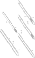
rail 5 according to the present invention can be seen inFigs. 5e and 5-f. Fig. 5a shows an embodiment where a friction surface, hook-and-loop fastener or glue/bonding can be used as a fastening means 20 for engagement with the underside of the binding orbinding components 2; 4 comprising at least one complementary locking device.Figs. 5a-f show rails 5 which are relatively short and intended only to extend to the forward part of the binding orbinding component 2. It should be understood that the rail can also extend further back under the binding orbinding component 2. -
Figs. 1a-c ,2a-2c ,3a-b ,4a-c ,11a-11e ,12 ,13 and14 , showing embodiments not according to the present invention per se and for illustration purposes only, also show a mountingplate 6 comprising alongitudinal channel 21 holding alongitudinal rail 5, the upper side of therail 5 comprising a plurality of longitudinal grooves 7; 20; 23 that form one part of a locking device. Furthermore, bindingcomponents 2 are shown whose underside comprises a plurality of complementary grooves that form the second part of the locking device. The grooves on therail 5 and the complementary grooves on the binding components are designed to engage with each other. At the same time, the longitudinal side edges of the mounting plate comprise aprofile 33 with undercuts and the binding orbinding components 2 comprise acomplementary profile 34. Several of the figures show that the binding components grip around and are locked to the mounting plate in that the profiles fit into each other. In a number of the illustrated embodiments, therail 5 and the binding components can be moved in the longitudinal direction when the parts mounting plate,rail 5 and binding components are assembled. -
Figs. 3a-b , showing embodiments not according to the present invention and for illustration purposes only, show arail 5 is fastened with a pin or the like in front of the binding orbinding components 2. -
Fig. 4a shows aplate 6 that is fastened onto the ski with screws in screw holes 22. Figs. b and c show an embodiment that can be glued or bonded to the ski. These embodiments also comprisepins 20 for attachment of the binding orbinding components 2. - The
rail 5 can, as mentioned, comprise grooves, pins and/or notches 7; 20; 23 that hold the binding or thebinding components 2. If the rail comprises a long row of notches or grooves, the binding or thebinding components 2 can be mounted/positioned on therail 5/mountingplate 6 in the desired position, ref.Fig. 7b , showing an embodiment not according to the present invention per se and for illustration purposes only.Fig. 7b actually shows only a few notches orgrooves 23 for theheel piece 4, but the same can be provided for the binding orbinding components 2, where only shown two notches are now shown for a fixed position. It is possible, e.g., to provide sufficient notches/grooves to allow the binding to be mounted within a longitudinal range of 3 or 5 cm (may be more or less, it is of no significance in this example). Thus, the binding orbinding components 2 are mounted/attached to the ski in the skier's neutral or desired longitudinal starting position, after which themotor 3 can move the binding or thebinding components 2 back and forth as desired during skiing. Different snow conditions can also make it desirable to change the skier's neutral starting position. Such a possibility may also be useful if the skier gains or loses weight. -
Fig. 7a shows a so-called "hybrid plate". In the mountingplate 6, a conventional binding can be attached without any dynamic system comprising amotor 3,rail 5 etc. The mountingplate 6 comprises fixed fastening notches/grooves 23. If the skier wishes to upgrade to a dynamic system, a rail can be placed in thegroove 24 and amotor 3 fastened on top of the rail in fastening means 25. In this case, the binding must be of a displaceable type that does not enter into engagement with the fixed notches/grooves 23. Themotor 3,rail 5 and binding orbinding components 2 shown inFigs. 3a-b would be suitable for aftermounting on a hybrid plate of this kind. - As an alternative to notches/grooves, the binding can also be attached/positioned/ connected to the rail with the aid of snap locks, screws, hook-and-loop fastener, adhesive material etc. ref.
Fig. 5a (hook-and-loop fastener) andFig. 5b (screws). Therail 5 and a binding can be moulded in one piece. In another embodiment, therail 5, a binding and a motor, optionally also other elements, can form an integral unit, such that it moves in aplate 6 or in the ski. -
Figs. 6e-i , showing embodiments not according to the present invention and for illustration purposes only, show different embodiments where the ski comprises a groove or achannel 21 able to house or accommodate an energy transfer means 22, 23. The energy transfer means 22 exhibits a worm screw capable of being turned. The energy transfer means 22 exhibits a rod in or on which the binding, or a part of the binding 2, is fastened. Here, it is fastened with the aid of a screw, but other alternatives can also be used.Figs. 10a-b , showing embodiments not according to the present invention and for illustration purposes only, show a groove or achannel 21 that is wholly or partly closed. In this embodiment, themotor 3 can either be placed in the ski, on top of the ski or in the binding. -
Fig. 5d , showing an embodiment not according to the present invention and for illustration purposes only, shows moreover arail 5 that can be pulled back and forth with the aid of a worm screw. This embodiment may be an alternative embodiment of that shown inFigs. 1a-c or6e . -
Figs. 10a-b show, as mentioned, an embodiment not according to the present invention and for illustration purposes only, where arail 5; 22; 23 or an energy transfer means runs in a groove or achannel 21 in the ski itself. In this embodiment, the ski itself functions as a mountingplate 6. Theopening 24 can house the energy transfer means and other elements such as motor, control system and/or battery.Figs. 8a and 8c , showing embodiments not according to the present invention and for illustration purposes only, show an alternative way of using the opening. Here, a mountingplate 6 is provided with anopen chamber 25 that can be placed in theopening 24 or a corresponding opening.Fig. 8c shows amotor 3 placed in thechamber 25, where it is able to pull on a rail lying above in the mountingplate 6.Fig. 8a shows aplate 6 that can be glued/bonded onto the ski,Fig. 8c showing aplate 6 that can be screwed onto the ski. Thechamber 25 can also hold elements such as control system and/or battery. -
Fig. 8b shows an embodiment of ashort plate 6, where theheel piece 4 is separate and fixed. -
Fig. 9a , showing an embodiment not according to the present invention and for illustration purposes only, shows an embodiment comprising twoplates 6, where a heel piece is movable with a rail that extends through both plates. -
Fig. 9b , showing an embodiment not according to the present invention and for illustration purposes only, shows standardised fastening means 25 at the front of the mountingplate 6. The advantage of these is that a motor, a battery, a closing plate etc. can all fit into the same fastening means, i.e., that they are interchangeable. -
Figs. 11a-e ,Figs. 17a-e and18a-c , showing embodiments not according to the present invention and for illustration purposes only, show differentmanual embodiments 13 of the invention where the motor has been replaced by a manipulatable moving andlocking mechanism 26, 27. Such a manual embodiment may be relevant for skiers who would like a less expensive product or who do not want the bother of advanced systems. This embodiment can also be a less expensive start package for a skier who would like the possibility of upgrading to a more advanced system at a later stage. This manipulatable moving andlocking mechanism 26, 27 fits in the standardised fastening means 25. The moving mechanism may comprise alever 26 that cooperates with a flexible tongue-like section 28 of therail 5. By tilting the lever back and forth, therail 5 and thus the binding, can also be moved. - In the specific embodiment shown in
Figs. 11a-e , , showing embodiments not according to the present invention and for illustration purposes only, the flexible tongue-like section 28 is arranged such that it bends up when thelever 26 is tilted upwards over the tilting point, and down on the other side. The point ofattachment 35 of the section to thelever 26 is chosen such that the longitudinal force on the rail is sufficiently large that the rail, and thus thebinding components 2, can be securely moved even though snow build-up or icing has occurred. -
Figs. 17a-e and18a-c , showing embodiments not according to the present invention and for illustration purposes only, show an embodiment like the one shown inFigs. 11a-e , where the point ofattachment 35 of the tongue-like section 28 to thelever 26 also comprisestransverse pins 36 that fit into suitable grooves ornotches 37, 37' in the fixed part of the moving and locking mechanism 27. The point ofattachment 35 of thesection 28 to thelever 26 can, in an embodiment, comprise a transverse stud with ends or pins 36 that project on each side of thelever 26. These projectingpins 36 fit intocomplementary notches 37, 37' in the fixed part of the moving and locking mechanism 27, one pair 27 in front of the lever's 26 point ofrotation 38, and one pair 27' to the rear. The advantage of this is that the energy from the skier via therail 5 is taken up directly by the fixed part of the moving and locking mechanism 27 without being transferred via various links, Thenotches 37, 37' can further be configured such that thepins 36 can be snapped into the notches by means of snap locks 39, thereby ensuring thepins 36 are held in place and cannot spring up during skiing. A solution of this kind will also help to lock thelever 26 in a locked horizontal direction, so as to prevent it from swinging up in a undesirable manner during skiing. If that were to happen, the binding would " float" loosely on top of the ski, which would in every way be unfavourable and perhaps even dangerous. -
Figs. 11a and16a-d , showing embodiments not according to the present invention and for illustration purposes only, show a separate tongue-like section 28 that is mounted on arail 5. Thesection 28 may also be part of the actual rail. e.g., in that the rail is basically sufficiently flexible (ref.Figs. 11b-e ) or in that the rail is tapered at the front. The rail can also be provided with a transverse line of weakness that forms a bending zone or bending point. Aseparate section 28 can also be fastened to the rail by means of a hinged joint.Figs. 16a-d show analternative rail 5 with asection 28. - In the embodiment shown in
Figs. 16a-d , showing embodiments not according to the present invention and for illustration purposes only, therail 5 comprises two sets of fivegrooves 23. It should be understood that fewer or more than fivegrooves 23 can be used, as well as fewer or more sets of grooves. The advantage of usingmore grooves 23 is that the binding orbinding components 2 can be pre-positioned before the binding orbinding components 2 are moved/displaced dynamically whilst in motion with the aid of amotor 3, optionally with the aid of a manual system. This provides several "layers" of positioning possibilities, e.g., in connection with user/skier adaptation (weight, weight change, proficiency), snow conditions or track profile. In the last-mentioned case, it is conceivable that the track profile permits a lot of poling and little skiing in the diagonal stride technique. In such an instance, the binding orbinding components 2 can be pre-positioned relatively far back so as to obtain different degrees of good glide when the position is changed dynamically whilst in motion. In the foremost dynamic position, it will be possible to have relatively good grip in a short steep hill. Conversely, if the track profile has many upward slopes and thus requires a great deal of skiing in the diagonal stride technique, the binding orbinding components 2 can be pre-positioned relatively far forwards thereby obtaining different degrees of good grip when the position is changed dynamically whilst in motion. In the rearmost dynamic position, it will be possible to have relatively good glide on flatter terrain. -
Figs. 11a-e , showing an embodiment not according to the present invention and for illustration purposes only, show arail 5 with one set of onegroove 23. It will be understood that this rail can instead comprise arail 5 of the type shown inFigs. 16a-d , i.e., havingmore grooves 23 in order to allow the aforementioned pre-positioning. The same applies to all the other illustrated embodiments comprising one or more sets of onegroove 23. -
Fig. 12 , showing an embodiment not according to the present invention and for illustration purposes only, shows an alternativemanual embodiment 13 comprising a rotary wheel 29 that moves the binding orbinding components 2 back and forth. Thehousing 30 fits and is fixed in the standardised fastening means 25. The rotary wheel 29 may comprise toothed wheels or cams (not shown) that pull the rail back and forth. The rotary wheel 29, the toothed wheel(s) and/or cam(s) are fixed relative to the ski in the standardised fastening means 25. -
Fig. 13 , showing an embodiment not according to the present invention and for illustration purposes only, shows a further alternative embodiment comprising alongitudinal groove 9 and a plurality of transverse grooves 10 that are arranged in ahousing 30. Thehousing 30 is fixedly mounted relative to the ski in the standardised fastening means 25. A lever 12 is mounted in connection with therail 5 such that the lever 12 can be moved from one transverse groove to another. The distance between grooves 10 determines the distance between the different positions of the binding 2. An overcentre mechanism, screw button or laterally arranged lever etc. is also conceivable. -
Fig. 14 , showing an embodiment not according to the present invention per se, but encompassing aspects that are relevant to the present invention, shows a locking plate or a locking housing 31. This can be configured such that it fits in the standardised fastening means 25. The grooves or notches 31 are configured so as to engage with corresponding grooves/notches 7 in therail 5 so as thereby to lock the binding orbinding components 2 fixed in one position. This position can per se be altered by removing the plate 31, adjusting the position of therail 5/binding orbinding components 2, and then replacing the plate 31. A single plate 31 of this kind can be a temporary solution or sold as a future-compatible system that can be upgraded with a manual or dynamic embodiment. - The embodiment shown in
Fig. 14 shows the mountingplate 6, therail 5 and thebinding components 2 as a three-part unit in which no reciprocal movement is allowed. This aspect is also relevant for the present invention. In this embodiment, therail 5 is locked to the mountingplate 6 in the longitudinal direction, and the binding components grip around the mounting plate and the rail such that the three parts form an interlocked three-part unit which cannot be moved in any direction, in this case with the aid of the locking plate 31.Fig. 14 shows a locking plate 31 that is arranged at the front, but it will be understood that it can be arranged at a point in the middle of or behind the mounting plate system. The locking devices between the mountingplate 6 and therail 5 and between therail 5 and thebinding components 2 prevent longitudinal movement of the unit, whilst the binding components that grip around the mounting plate and the rail prevent movement in all other directions.Fig. 14 shows use of a locking plate 31, but the rail can also be secured in the longitudinal direction with the aid of other locking devices. An embodiment of such alternative locking devices can comprise locking devices between therail 5 and the mountingplate 6, either an intermeshing solution (i.e., a form of direct interlocking) or one or more intermediate, separate locking devices. In both the last-mentioned cases, the locking devices between therail 5 and the mountingplate 6 can be located underneath therail 5 or around the edge of therail 5. - An embodiment of direct interlocking according to the present invention is shown in
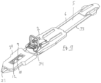
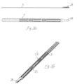
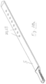
Fig. 19 . In the illustrated embodiment, therail 5 comprises "wings" 41 that fit intocomplementary pockets 42 in the mountingplate 6. The mountingplate 6 can comprise a plurality of pockets, so that the longitudinal position of therail 5 can be adjusted. In addition, there may be a number ofgrooves 23 or similar locking means on top of therail 5 for additional possible positioning. In an embodiment, therail 5 shown inFig. 19 can be reversed or turned, both transversely and longitudinally. Turning it upside down will give different interfaces above and below therail 5, such that different types of bindings, e.g., from different manufacturers can be mounted. A similar possibility may conceivably be obtained by turning the rail in the longitudinal direction, in addition to being able to obtain an adjustment of position in the longitudinal direction: Instead of wings/pockets, similar solutions are possible. e.g., complementary undercuts/grooves, complementary notches, snap locks, swivel locks etc. -
Figs. 20a-c , showing embodiments not according to the present invention and for illustration purposes only, show how interface can be varied and adapted to different use and/or different binding systems. The illustratedrail 5 is a manual embodiment, but it will be understood that it could just as easily be a dynamic or fixed embodiment. - The aforementioned manual embodiment can also be used as a handy spare part that can be taken along during use. If the skier should run into problems with an electric motor, e.g., in that it runs out of battery, is damaged or starts to run sluggishly, the
motor 3 can easily be changed and replaced with the manual embodiment as it has the standardised fastening means 25. The standardised fastening means 25 can be used by both manual and dynamic/electric elements, such that everything can be interchangeable. - The manual embodiments will per se not allow the dynamic positioning/gearing that has been referred to above, but will allow future upgrading to a dynamic system or be a temporary alternative. In certain cases, the skier may wish to use a manual system, e.g., during expeditions or on longer trips without access to electricity. The system can thus be modular.
- The positions or the positioning of the binding or
binding components 2 mentioned above can be discrete or continuous. - If the system is electric and makes use of electrical signals, these signals can be given or sent from buttons, levers, switches, sensitive zones or similar means, which, for example, can be arranged on a glove or ski pole. Such means could then be said to constitute control or operating means. Other locations and actuating methods are also conceivable. For example, there could be three buttons, "forwards/good grip", "neutral/standard" and "backwards/good glide". The system could also be stepless.
- In addition, there could be a separate position for fastening the ski shoe to the binding/ski. It is, e.g., conceivable that in addition to a forward, centre and rear position, there is a "fourth position" that opens the binding. In this fourth position, the binding can be open and the skier can put on or take off the ski. If the skier wishes to put the ski on, the binding can be locked by being moved to the forward, middle or rear position (there could of course be more positions). Alternatively, the binding could be locked electrically in the fourth position. This aspect can also be combined with a step-in solution, where the skier can step into the binding in any position, but must move the binding to the fourth position for the step-in binding to open. In any case, it is possible to provide a manual open/close system that allows opening in emergencies or in a simpler version of the system.
- Although an
electric motor 3 is described, a pneumatic system, hydraulic system, mechanical system etc. that is capable of pushing the binding or thebinding components 2 back and forth between different longitudinal positions can also be used. Such alternative systems can be electrically actuatable. - If an
electric motor 3 is used, the system must comprise an energy source 7 in the form of an energy storage element (battery, capacitor, spring/dynamo etc.) This or these may be arranged in connection with themotor 3, at another point on the binding or the ski, in the shoe or at a point on the skier's body. Furthermore, the system may comprise a signal transponder or other communication means/microprocessor that receives a signal, processes it and sends a signal on to themotor 3 causing it to push the binding back and forth. - The motor, the manual embodiment or the locked embodiment can be attached to the ski/plate in different ways. The fact that they are lockably connected results in the advantages mentioned above, i.e., that the skier has the option of changing or upgrading sub-elements. This applies not only to the motor, the manual embodiment or the locked embodiment, but also to the rail, binding, battery etc.
- Since the forces transferred from the skier via the binding to the ski will be large, the system may comprise elements that lock the binding in the selected position after the
motor 3 has displaced the binding (only shown for the manual system). The locking element should in that case be of such a kind that it withstands strong applied forces. Instead of separate locking elements, the locking element may be a part of theelectric motor 3 or a pneumatic system, hydraulic system, mechanical system etc. - In an embodiment, the locking element may be arranged in connection with the electromotor, e.g., in that a rotating shaft from a motor, optionally via a gearing, is locked in the axial direction. The shaft can thus rotate freely whilst axial forces that are transferred from the binding to the shaft are taken up by the locking element. If the shaft from the electromotor transfers rotational forces via a simple gear system to another shaft, the shaft from the electromotor will in any case not be affected by any axial play or migration that may arise, either through necessary tolerances or wear in the locking element.
- One or more sensors, in or in connection with a electric actuator, the
motor 3 or pneumatic system, hydraulic system, mechanical system etc. can optionally sense and send a signal back to the transponder/microprocessor with information on the position and state of the binding. - It will be understood that an electric version of a binding used with this system in most cases should be sealed or protected from water ingress. Ingress of snow, ice and condensation can also pose a problem against which the system can or should be protected. To mitigate condensation problems, heating elements can be arranged on the inside of the wholly or partly sealed chambers, e.g., in the form of electric resistance/heat wires that emit sufficient heat to cause the condensation to evaporate and penetrate out of the system. One or more of the elements in the system, e.g., the biased spring or springs can per se form such electric resistance/heat wires. Such a drying process can be initiated automatically or manually in connection with charging the power source, i.e., preferably a battery. Alternatively, condensation problems can be mitigated by providing suitable air vents or the like. These can be arranged such that condensation escapes whist snow and ice are not admitted.
- An aspect of the present invention is that all the elements, including electromotor, binding, plate/interface (interface usually designates the interface between plate and binding. Different types of bindings and/or binding manufacturers can have different interface), transfer element, fastening means on the shoe/sole etc., can be made independent of one another, i.e., that each element can be improved and changed individually without other elements necessarily being affected or having to be changed. Thus, each element can also be manufactured as "off-the-shelf items" that can be used for different norms, systems and areas of utilisation (professional, performance, touring, back-country etc.).
- The plate can per se be replaceable. Different types of bindings can be configured to fit the plate. The transfer means can fit different types of bindings at one end, whilst it fits different types of electromotor at the other end.
- In the above examples and embodiments, a binding system is described that is adjusted as desired by the skier, that is to say, that the skier himself decides what position the binding should have on the ski by sending a signal to the binding system, for example, by pressing on buttons or the like on his glove or ski pole. A fully or semi-automatic system is also conceivable where different sensors in the binding system gather relevant information, such as speed, angles, acceleration, application of force etc. for calculating what the optimal position for the binding is, after which movement of the binding takes place automatically. Such a system can be overridden by manual buttons if the skier is not satisfied with the position of the binding.
- The examples above show that the binding or
binding components 2 are moved as a whole. Individual elements of the binding, e.g., flexor(s), gripping mechanism or other parts can also be moved independent of each other or some elements, but not all. Then a part of the binding will remain fixed whilst other parts are moved. - An aspect of the invention is that the mounting
plate 6 is arranged on a top surface of the ski and where the mountingplate 6 comprises longitudinal side edges that have aprofile 33 with undercuts for longitudinal positioning and attachment of the binding, or thebinding component 2; 4 with the aid of acomplementary profile 34 on the binding or thebinding components 2; 4. - An aspect of the invention is that the mounting
plate 6 comprises alongitudinal channel 21 that houses alongitudinal rail 5, where the upper side of therail 5 comprises at least onelocking device 20; 23, and where the underside of the binding orbinding components 2; 4 comprises at least one complementary locking device. - Anaspect of the invention is that the locking device on the rail and the complementary locking device on the binding or
binding component 2; 4 are designed to lock together whilst the complementary profile on the binding orbinding component 2; 4 grips around the profile with undercuts on the mounting plate. - A further aspect of the invention is that the
rail 5 is designed to sit firmly in the channel. - A further aspect of the invention is that the
rail 5 comprises locking devices on the underside or around the edge that cooperates with complementary locking devices in the mounting plate.
Claims (3)
- A cross-country mounting plate (6) system comprising:i) a cross-country binding or binding component (2; 4),ii) a mounting plate (6) arrangable on the top surface of a cross-county ski, the mounting plate (6) comprising longitudinal side edges having a profile (33) with undercuts for longitudinal positioning and attachment of the cross-country binding or binding component (2; 4) by means of a complementary profile (34) on the cross-country binding or binding component (2; 4),iii) the mounting plate (6) comprising a longitudinal channel (21) that houses a longitudinal rail (5), andiv) the rail (5), vii) the cross-country binding or binding components grip around (2;4) the mounting plate (6) and the interchangeable rail (5) such that the three parts form an interlocked three-part unit which cannot be moved in any direction.
characterized in thatv) the rail (5) is an interchangeable rail (5), where the interchangeable rail (5) is locked to the mounting plate (6) in the longitudinal direction, where the interchangeable rail (5) comprises a locking device on the underside or around the edge that cooperates with complementary locking devices in the mounting plate, andvi) the upper side of the interchangeable rail (5) comprising at least one locking device (20; 23), and the underside of the cross-country binding or binding component (2; 4) comprising at least one complementary locking device. - A mounting system according to claim 1, wherein-the cross-country binding or binding components (2) can be discretely or continuously positioned on the interchangeable longitudinal rail (5).
- A mounting system according to claim 1, wherein different types of cross-country bindings can be configured to fit the mounting plate.
Applications Claiming Priority (2)
| Application Number | Priority Date | Filing Date | Title |
|---|---|---|---|
| NO20170170A NO20170170A1 (en) | 2017-02-03 | 2017-02-03 | Mounting system for binding |
| PCT/NO2018/050029 WO2018143822A1 (en) | 2017-02-03 | 2018-02-02 | Mounting plate with rail for a binding |
Publications (2)
| Publication Number | Publication Date |
|---|---|
| EP3576854A1 EP3576854A1 (en) | 2019-12-11 |
| EP3576854B1 true EP3576854B1 (en) | 2025-05-07 |
Family
ID=60813938
Family Applications (2)
| Application Number | Title | Priority Date | Filing Date |
|---|---|---|---|
| EP17822052.1A Active EP3576853B1 (en) | 2017-02-03 | 2017-11-22 | Mounting plate and mounting plate system for a ski binding |
| EP18713382.2A Active EP3576854B1 (en) | 2017-02-03 | 2018-02-02 | Mounting plate with rail for a binding |
Family Applications Before (1)
| Application Number | Title | Priority Date | Filing Date |
|---|---|---|---|
| EP17822052.1A Active EP3576853B1 (en) | 2017-02-03 | 2017-11-22 | Mounting plate and mounting plate system for a ski binding |
Country Status (8)
| Country | Link |
|---|---|
| US (2) | US10933297B2 (en) |
| EP (2) | EP3576853B1 (en) |
| CN (2) | CN110382060A (en) |
| CA (2) | CA3052562A1 (en) |
| EA (2) | EA036282B1 (en) |
| FI (2) | FI3576853T3 (en) |
| NO (1) | NO20170170A1 (en) |
| WO (2) | WO2018143815A1 (en) |
Families Citing this family (5)
| Publication number | Priority date | Publication date | Assignee | Title |
|---|---|---|---|---|
| NO345089B1 (en) * | 2018-11-14 | 2020-09-21 | Rottefella As | LOCKING DEVICE FOR LOCKING SKI BINDING TO MOUNTING PLATE |
| FR3093648B1 (en) * | 2019-03-13 | 2021-10-29 | Salomon Sas | Gliding board retainer |
| NO345757B1 (en) * | 2019-10-29 | 2021-07-12 | Rottefella As | Removable ski binding |
| AT524636A1 (en) | 2020-12-23 | 2022-07-15 | Fischer Sports Gmbh | Storage device for a ski binding |
| NO349347B1 (en) * | 2024-10-02 | 2025-12-15 | Rottefella As | Cross-country ski binding with integrated rail |
Family Cites Families (34)
| Publication number | Priority date | Publication date | Assignee | Title |
|---|---|---|---|---|
| CH652610A5 (en) * | 1980-10-28 | 1985-11-29 | Tmc Corp | LOCKING DEVICE FOR A SAFETY SKI BINDING. |
| FR2684888B1 (en) | 1991-12-13 | 1994-02-04 | Salomon Sa | INTERFACE PLATE FOR THE SLIDE OF A MOBILE ELEMENT, ESPECIALLY AN ALPINE FIXING ELEMENT. |
| FR2689775B1 (en) * | 1992-04-10 | 1994-07-08 | Salomon Sa | INTERFACE DEVICE BETWEEN A SKI AND FIXING ELEMENTS, PARTICULARLY ALPINE FIXING. |
| US5785342A (en) * | 1996-07-30 | 1998-07-28 | Bronson; Henry D. | Ski binding dampening assembly |
| NO306540B1 (en) * | 1997-06-20 | 1999-11-22 | Linken Binding | Ski Binding |
| US7104564B2 (en) * | 2000-08-10 | 2006-09-12 | Martin Ralph M | Backwards release ski binding |
| US6659494B1 (en) * | 2000-08-10 | 2003-12-09 | Ralph M. Martin | Backwards release ski binding on a pivot plate mount |
| DE10052067A1 (en) * | 2000-10-19 | 2002-05-02 | Marker Deutschland Gmbh | Ski or. snowboard binding |
| EP1314458A1 (en) * | 2001-11-23 | 2003-05-28 | HTM Sport- und Freizeitgeräte Aktiengesellschaft | Adjustable ski binding device on a ski |
| DE10254471A1 (en) | 2002-11-21 | 2004-06-03 | Madsus A/S | Ski with binding assembly aid, process for producing such a ski and corresponding assembly aid |
| FR2877233B1 (en) * | 2004-10-28 | 2007-01-19 | Look Fixations Sa Sa | ADJUSTING DEVICE FOR ACCESSORY SUCH AS A SKI FIXING TALONNIER |
| US9776065B2 (en) * | 2005-01-10 | 2017-10-03 | Rottefella As | Ski, or similar device for sliding on snow, having a mounting aid for a binding |
| FR2894836B1 (en) * | 2005-12-16 | 2008-02-22 | Salomon Sa | BACKGROUND SKI SET AND DOWNHOLE SKI FIXING DEVICE |
| FR2899121B1 (en) * | 2006-03-29 | 2008-07-04 | Salomon Sa | BACKGROUND SKI SET AND DOWNHOLE SKI FIXING DEVICE |
| FR2901486A1 (en) * | 2006-05-24 | 2007-11-30 | Salomon Sa | ASSEMBLY COMPRISING A SLIDING BOARD AND A DEVICE FOR RETAINING A FOOTWEAR ARTICLE ON THE BOARD |
| US20080047168A1 (en) * | 2006-06-23 | 2008-02-28 | Svensson John E | Nordic ski boot support and attachment structure |
| FR2912317B1 (en) * | 2007-02-13 | 2009-05-08 | Salomon Sa | ASSEMBLY COMPRISING A DEVICE FOR THE SOLIDARIZATION OF A PLATINUM. |
| FR2912663B1 (en) * | 2007-02-19 | 2009-07-10 | Salomon Sa | SECURITY FASTENING FOR SKI SHOE |
| FR2927544B1 (en) * | 2008-02-15 | 2010-08-13 | Salomon Sa | DEVICE FOR RECEIVING A SHOE ON A SPORT MACHINE |
| FR2929531B3 (en) * | 2008-04-08 | 2010-08-13 | Salomon Sas | ASSEMBLY COMPRISING A SLIDING BOARD AND A RETAINING DEVICE FOR A FOOTWEAR ARTICLE. |
| EP2453995B1 (en) | 2009-07-17 | 2014-06-18 | Rottefella AS | Flexor with fastening clip |
| NO331707B1 (en) | 2010-09-15 | 2012-02-27 | Rottefella As | Assembly for connecting a boot to a ski, as well as the intermediate piece for use in said assembly |
| WO2012045329A1 (en) * | 2010-10-04 | 2012-04-12 | Madshus As | Ski binding |
| DE102010048963A1 (en) * | 2010-10-20 | 2012-04-26 | Marker Deutschland Gmbh | Binding for a sliding board with longitudinally adjustable holding units |
| DE102012206879B4 (en) * | 2012-04-25 | 2021-12-23 | Marker Deutschland Gmbh | Lightweight ski binding with increased release security with support device |
| FI124134B (en) * | 2012-07-02 | 2014-03-31 | One Way Sport Oy | Ski-to-mono bond |
| NO336669B1 (en) | 2012-11-19 | 2015-10-19 | Rottefella As | Ski Binding |
| FR2998186B1 (en) * | 2012-11-20 | 2015-01-09 | Salomon Sas | FIXING A SHOE ON A SLIDING BOARD AND SLIDING BOARD COMPRISING SUCH A FIXATION |
| NO20130873A1 (en) * | 2013-06-24 | 2014-12-25 | Rottefella As | Mounting system for mounting bindings on skis |
| NO339366B1 (en) | 2015-03-12 | 2016-12-05 | Rottefella As | System for optional dynamic positioning of a ski binding |
| EP3307404A4 (en) * | 2015-06-12 | 2019-03-13 | Hitch, Douglas A. | MECHANICAL TRACTION FOR A SUBSTANTIVE SKI |
| US20170080325A1 (en) * | 2015-09-18 | 2017-03-23 | Rossland Binding Company | Remote release ski binding |
| NO340839B1 (en) * | 2015-11-30 | 2017-06-26 | Rottefella As | System for optional dynamic positioning of a ski binding on a ski |
| WO2018170119A1 (en) * | 2017-03-14 | 2018-09-20 | Stop River Development LLC | Processor-controlled snow sport boot binding |
-
2017
- 2017-02-03 NO NO20170170A patent/NO20170170A1/en unknown
- 2017-11-22 WO PCT/NO2017/050303 patent/WO2018143815A1/en not_active Ceased
- 2017-11-22 CN CN201780087895.9A patent/CN110382060A/en active Pending
- 2017-11-22 US US16/483,603 patent/US10933297B2/en not_active Expired - Fee Related
- 2017-11-22 EP EP17822052.1A patent/EP3576853B1/en active Active
- 2017-11-22 FI FIEP17822052.1T patent/FI3576853T3/en active
- 2017-11-22 EA EA201991824A patent/EA036282B1/en not_active IP Right Cessation
- 2017-11-22 CA CA3052562A patent/CA3052562A1/en not_active Abandoned
-
2018
- 2018-02-02 EA EA201991823A patent/EA038151B1/en unknown
- 2018-02-02 WO PCT/NO2018/050029 patent/WO2018143822A1/en not_active Ceased
- 2018-02-02 FI FIEP18713382.2T patent/FI3576854T3/en active
- 2018-02-02 US US16/483,609 patent/US11033798B2/en not_active Expired - Fee Related
- 2018-02-02 CA CA3052563A patent/CA3052563A1/en active Pending
- 2018-02-02 EP EP18713382.2A patent/EP3576854B1/en active Active
- 2018-02-02 CN CN201880016251.5A patent/CN110382061B/en not_active Expired - Fee Related
Also Published As
| Publication number | Publication date |
|---|---|
| US10933297B2 (en) | 2021-03-02 |
| EA036282B1 (en) | 2020-10-21 |
| EA201991824A1 (en) | 2020-02-03 |
| US11033798B2 (en) | 2021-06-15 |
| CN110382061A (en) | 2019-10-25 |
| WO2018143815A1 (en) | 2018-08-09 |
| CA3052562A1 (en) | 2018-08-09 |
| NO342264B1 (en) | 2018-04-30 |
| WO2018143822A1 (en) | 2018-08-09 |
| CN110382061B (en) | 2022-02-08 |
| FI3576853T3 (en) | 2024-12-13 |
| EP3576853B1 (en) | 2024-09-25 |
| US20200094126A1 (en) | 2020-03-26 |
| US20200114248A1 (en) | 2020-04-16 |
| EA201991823A1 (en) | 2020-02-03 |
| NO20170170A1 (en) | 2018-04-30 |
| CA3052563A1 (en) | 2018-08-09 |
| FI3576854T3 (en) | 2025-07-04 |
| EA038151B1 (en) | 2021-07-14 |
| EP3576853A1 (en) | 2019-12-11 |
| CN110382060A (en) | 2019-10-25 |
| EP3576854A1 (en) | 2019-12-11 |
Similar Documents
| Publication | Publication Date | Title |
|---|---|---|
| US11033798B2 (en) | Mounting plate with rail for a binding | |
| EP3383511B1 (en) | System for optional dynamic positioning of a ski binding on a ski | |
| US9937407B2 (en) | Splitboard binding | |
| US9884243B2 (en) | Splitboard binding with step in rear securing feature and locking crampon | |
| US7661695B2 (en) | Cross-country ski assembly and cross-country ski binding | |
| US9242167B2 (en) | Ski binding heel unit | |
| WO2022262994A1 (en) | Powered device for propelling a surface on snow | |
| US5941555A (en) | Snowboard boot binding mechanism | |
| CA2468217A1 (en) | Binding for coupling a shoe to a snowboard and the like | |
| EP0463107A4 (en) | Snowboard binding | |
| US8714578B2 (en) | Safety binding for ski touring | |
| EP1015080A1 (en) | Improved boot binding system for a snowboard | |
| EP2682165B1 (en) | Binding between a ski and a boot | |
| EA034724B1 (en) | System for optional dynamic positioning a ski binding | |
| US20010010422A1 (en) | Assembly for retaining a boot on an apparatus for gliding or walking on snow or ice | |
| EP2135645B1 (en) | Dismountable ski binding | |
| US5735063A (en) | Skishoes with brakes and extension and retraction stops therefor | |
| EP1387717A1 (en) | Binding, particularly for fastening a shoe to a snowboard |
Legal Events
| Date | Code | Title | Description |
|---|---|---|---|
| STAA | Information on the status of an ep patent application or granted ep patent |
Free format text: STATUS: UNKNOWN |
|
| STAA | Information on the status of an ep patent application or granted ep patent |
Free format text: STATUS: THE INTERNATIONAL PUBLICATION HAS BEEN MADE |
|
| PUAI | Public reference made under article 153(3) epc to a published international application that has entered the european phase |
Free format text: ORIGINAL CODE: 0009012 |
|
| STAA | Information on the status of an ep patent application or granted ep patent |
Free format text: STATUS: REQUEST FOR EXAMINATION WAS MADE |
|
| 17P | Request for examination filed |
Effective date: 20190816 |
|
| AK | Designated contracting states |
Kind code of ref document: A1 Designated state(s): AL AT BE BG CH CY CZ DE DK EE ES FI FR GB GR HR HU IE IS IT LI LT LU LV MC MK MT NL NO PL PT RO RS SE SI SK SM TR |
|
| AX | Request for extension of the european patent |
Extension state: BA ME |
|
| DAV | Request for validation of the european patent (deleted) | ||
| DAX | Request for extension of the european patent (deleted) | ||
| STAA | Information on the status of an ep patent application or granted ep patent |
Free format text: STATUS: EXAMINATION IS IN PROGRESS |
|
| 17Q | First examination report despatched |
Effective date: 20220311 |
|
| REG | Reference to a national code |
Ref country code: NO Ref legal event code: TC |
|
| RAP3 | Party data changed (applicant data changed or rights of an application transferred) |
Owner name: ROTTEFELLA AS |
|
| REG | Reference to a national code |
Ref country code: DE Ref legal event code: R079 Free format text: PREVIOUS MAIN CLASS: A63C0009080000 Ipc: A63C0005120000 Ref country code: DE Ref legal event code: R079 Ref document number: 602018081702 Country of ref document: DE Free format text: PREVIOUS MAIN CLASS: A63C0009080000 Ipc: A63C0005120000 |
|
| GRAP | Despatch of communication of intention to grant a patent |
Free format text: ORIGINAL CODE: EPIDOSNIGR1 |
|
| STAA | Information on the status of an ep patent application or granted ep patent |
Free format text: STATUS: GRANT OF PATENT IS INTENDED |
|
| RIC1 | Information provided on ipc code assigned before grant |
Ipc: A63C 9/086 20120101ALI20241206BHEP Ipc: A63C 9/20 20120101ALI20241206BHEP Ipc: A63C 9/00 20120101ALI20241206BHEP Ipc: A63C 5/12 20060101AFI20241206BHEP |
|
| INTG | Intention to grant announced |
Effective date: 20241219 |
|
| P01 | Opt-out of the competence of the unified patent court (upc) registered |
Free format text: CASE NUMBER: APP_1971/2025 Effective date: 20250113 |
|
| GRAS | Grant fee paid |
Free format text: ORIGINAL CODE: EPIDOSNIGR3 |
|
| GRAA | (expected) grant |
Free format text: ORIGINAL CODE: 0009210 |
|
| STAA | Information on the status of an ep patent application or granted ep patent |
Free format text: STATUS: THE PATENT HAS BEEN GRANTED |
|
| AK | Designated contracting states |
Kind code of ref document: B1 Designated state(s): AL AT BE BG CH CY CZ DE DK EE ES FI FR GB GR HR HU IE IS IT LI LT LU LV MC MK MT NL NO PL PT RO RS SE SI SK SM TR |
|
| REG | Reference to a national code |
Ref country code: GB Ref legal event code: FG4D |
|
| REG | Reference to a national code |
Ref country code: CH Ref legal event code: EP |
|
| REG | Reference to a national code |
Ref country code: DE Ref legal event code: R096 Ref document number: 602018081702 Country of ref document: DE |
|
| REG | Reference to a national code |
Ref country code: IE Ref legal event code: FG4D |
|
| REG | Reference to a national code |
Ref country code: FI Ref legal event code: FGE |
|
| REG | Reference to a national code |
Ref country code: SE Ref legal event code: TRGR |
|
| REG | Reference to a national code |
Ref country code: NL Ref legal event code: MP Effective date: 20250507 |
|
| PG25 | Lapsed in a contracting state [announced via postgrant information from national office to epo] |
Ref country code: PT Free format text: LAPSE BECAUSE OF FAILURE TO SUBMIT A TRANSLATION OF THE DESCRIPTION OR TO PAY THE FEE WITHIN THE PRESCRIBED TIME-LIMIT Effective date: 20250908 Ref country code: ES Free format text: LAPSE BECAUSE OF FAILURE TO SUBMIT A TRANSLATION OF THE DESCRIPTION OR TO PAY THE FEE WITHIN THE PRESCRIBED TIME-LIMIT Effective date: 20250507 |
|
| REG | Reference to a national code |
Ref country code: LT Ref legal event code: MG9D |
|
| PG25 | Lapsed in a contracting state [announced via postgrant information from national office to epo] |
Ref country code: GR Free format text: LAPSE BECAUSE OF FAILURE TO SUBMIT A TRANSLATION OF THE DESCRIPTION OR TO PAY THE FEE WITHIN THE PRESCRIBED TIME-LIMIT Effective date: 20250808 |
|
| PG25 | Lapsed in a contracting state [announced via postgrant information from national office to epo] |
Ref country code: NL Free format text: LAPSE BECAUSE OF FAILURE TO SUBMIT A TRANSLATION OF THE DESCRIPTION OR TO PAY THE FEE WITHIN THE PRESCRIBED TIME-LIMIT Effective date: 20250507 Ref country code: PL Free format text: LAPSE BECAUSE OF FAILURE TO SUBMIT A TRANSLATION OF THE DESCRIPTION OR TO PAY THE FEE WITHIN THE PRESCRIBED TIME-LIMIT Effective date: 20250507 |
|
| PG25 | Lapsed in a contracting state [announced via postgrant information from national office to epo] |
Ref country code: BG Free format text: LAPSE BECAUSE OF FAILURE TO SUBMIT A TRANSLATION OF THE DESCRIPTION OR TO PAY THE FEE WITHIN THE PRESCRIBED TIME-LIMIT Effective date: 20250507 |
|
| PG25 | Lapsed in a contracting state [announced via postgrant information from national office to epo] |
Ref country code: HR Free format text: LAPSE BECAUSE OF FAILURE TO SUBMIT A TRANSLATION OF THE DESCRIPTION OR TO PAY THE FEE WITHIN THE PRESCRIBED TIME-LIMIT Effective date: 20250507 |
|
| PG25 | Lapsed in a contracting state [announced via postgrant information from national office to epo] |
Ref country code: RS Free format text: LAPSE BECAUSE OF FAILURE TO SUBMIT A TRANSLATION OF THE DESCRIPTION OR TO PAY THE FEE WITHIN THE PRESCRIBED TIME-LIMIT Effective date: 20250807 |
|
| PG25 | Lapsed in a contracting state [announced via postgrant information from national office to epo] |
Ref country code: IS Free format text: LAPSE BECAUSE OF FAILURE TO SUBMIT A TRANSLATION OF THE DESCRIPTION OR TO PAY THE FEE WITHIN THE PRESCRIBED TIME-LIMIT Effective date: 20250907 |
|
| PG25 | Lapsed in a contracting state [announced via postgrant information from national office to epo] |
Ref country code: LV Free format text: LAPSE BECAUSE OF FAILURE TO SUBMIT A TRANSLATION OF THE DESCRIPTION OR TO PAY THE FEE WITHIN THE PRESCRIBED TIME-LIMIT Effective date: 20250507 |
|
| PG25 | Lapsed in a contracting state [announced via postgrant information from national office to epo] |
Ref country code: DK Free format text: LAPSE BECAUSE OF FAILURE TO SUBMIT A TRANSLATION OF THE DESCRIPTION OR TO PAY THE FEE WITHIN THE PRESCRIBED TIME-LIMIT Effective date: 20250507 Ref country code: SM Free format text: LAPSE BECAUSE OF FAILURE TO SUBMIT A TRANSLATION OF THE DESCRIPTION OR TO PAY THE FEE WITHIN THE PRESCRIBED TIME-LIMIT Effective date: 20250507 |
|
| PGFP | Annual fee paid to national office [announced via postgrant information from national office to epo] |
Ref country code: FI Payment date: 20251210 Year of fee payment: 9 |
|
| PGFP | Annual fee paid to national office [announced via postgrant information from national office to epo] |
Ref country code: FR Payment date: 20251210 Year of fee payment: 9 |
|
| PGFP | Annual fee paid to national office [announced via postgrant information from national office to epo] |
Ref country code: SE Payment date: 20251210 Year of fee payment: 9 |
|
| PG25 | Lapsed in a contracting state [announced via postgrant information from national office to epo] |
Ref country code: CZ Free format text: LAPSE BECAUSE OF FAILURE TO SUBMIT A TRANSLATION OF THE DESCRIPTION OR TO PAY THE FEE WITHIN THE PRESCRIBED TIME-LIMIT Effective date: 20250507 |
|
| PG25 | Lapsed in a contracting state [announced via postgrant information from national office to epo] |
Ref country code: EE Free format text: LAPSE BECAUSE OF FAILURE TO SUBMIT A TRANSLATION OF THE DESCRIPTION OR TO PAY THE FEE WITHIN THE PRESCRIBED TIME-LIMIT Effective date: 20250507 |
|
| PG25 | Lapsed in a contracting state [announced via postgrant information from national office to epo] |
Ref country code: RO Free format text: LAPSE BECAUSE OF FAILURE TO SUBMIT A TRANSLATION OF THE DESCRIPTION OR TO PAY THE FEE WITHIN THE PRESCRIBED TIME-LIMIT Effective date: 20250507 Ref country code: SK Free format text: LAPSE BECAUSE OF FAILURE TO SUBMIT A TRANSLATION OF THE DESCRIPTION OR TO PAY THE FEE WITHIN THE PRESCRIBED TIME-LIMIT Effective date: 20250507 |
|
| PG25 | Lapsed in a contracting state [announced via postgrant information from national office to epo] |
Ref country code: IT Free format text: LAPSE BECAUSE OF FAILURE TO SUBMIT A TRANSLATION OF THE DESCRIPTION OR TO PAY THE FEE WITHIN THE PRESCRIBED TIME-LIMIT Effective date: 20250507 |
|
| REG | Reference to a national code |
Ref country code: DE Ref legal event code: R097 Ref document number: 602018081702 Country of ref document: DE |
|
| PLBE | No opposition filed within time limit |
Free format text: ORIGINAL CODE: 0009261 |
|
| STAA | Information on the status of an ep patent application or granted ep patent |
Free format text: STATUS: NO OPPOSITION FILED WITHIN TIME LIMIT |
|
| REG | Reference to a national code |
Ref country code: CH Ref legal event code: L10 Free format text: ST27 STATUS EVENT CODE: U-0-0-L10-L00 (AS PROVIDED BY THE NATIONAL OFFICE) Effective date: 20260318 |
|
| PGFP | Annual fee paid to national office [announced via postgrant information from national office to epo] |
Ref country code: NO Payment date: 20260115 Year of fee payment: 9 Ref country code: DE Payment date: 20260113 Year of fee payment: 9 |
|
| PGFP | Annual fee paid to national office [announced via postgrant information from national office to epo] |
Ref country code: AT Payment date: 20260113 Year of fee payment: 9 |
|
| 26N | No opposition filed |
Effective date: 20260210 |