EP3576645B1 - LAMINATE MEMBRANE, IMPLANT COMPRISING THE LAMINATE MEMBRANE AND METHOD FOR PRODUCING THE SAME - Google Patents
LAMINATE MEMBRANE, IMPLANT COMPRISING THE LAMINATE MEMBRANE AND METHOD FOR PRODUCING THE SAME Download PDFInfo
- Publication number
- EP3576645B1 EP3576645B1 EP18726136.7A EP18726136A EP3576645B1 EP 3576645 B1 EP3576645 B1 EP 3576645B1 EP 18726136 A EP18726136 A EP 18726136A EP 3576645 B1 EP3576645 B1 EP 3576645B1
- Authority
- EP
- European Patent Office
- Prior art keywords
- covering layer
- layer
- inner layer
- laminate membrane
- covering
- Prior art date
- Legal status (The legal status is an assumption and is not a legal conclusion. Google has not performed a legal analysis and makes no representation as to the accuracy of the status listed.)
- Active
Links
Images



Classifications
-
- A—HUMAN NECESSITIES
- A61—MEDICAL OR VETERINARY SCIENCE; HYGIENE
- A61B—DIAGNOSIS; SURGERY; IDENTIFICATION
- A61B17/00—Surgical instruments, devices or methods
- A61B17/12—Surgical instruments, devices or methods for ligaturing or otherwise compressing tubular parts of the body, e.g. blood vessels or umbilical cord
- A61B17/12022—Occluding by internal devices, e.g. balloons or releasable wires
- A61B17/12099—Occluding by internal devices, e.g. balloons or releasable wires characterised by the location of the occluder
- A61B17/12109—Occluding by internal devices, e.g. balloons or releasable wires characterised by the location of the occluder in a blood vessel
-
- A—HUMAN NECESSITIES
- A61—MEDICAL OR VETERINARY SCIENCE; HYGIENE
- A61B—DIAGNOSIS; SURGERY; IDENTIFICATION
- A61B17/00—Surgical instruments, devices or methods
- A61B17/12—Surgical instruments, devices or methods for ligaturing or otherwise compressing tubular parts of the body, e.g. blood vessels or umbilical cord
- A61B17/12022—Occluding by internal devices, e.g. balloons or releasable wires
- A61B17/12131—Occluding by internal devices, e.g. balloons or releasable wires characterised by the type of occluding device
- A61B17/1214—Coils or wires
- A61B17/1215—Coils or wires comprising additional materials, e.g. thrombogenic, having filaments, having fibers, being coated
-
- B—PERFORMING OPERATIONS; TRANSPORTING
- B32—LAYERED PRODUCTS
- B32B—LAYERED PRODUCTS, i.e. PRODUCTS BUILT-UP OF STRATA OF FLAT OR NON-FLAT, e.g. CELLULAR OR HONEYCOMB, FORM
- B32B27/00—Layered products comprising a layer of synthetic resin
- B32B27/06—Layered products comprising a layer of synthetic resin as the main or only constituent of a layer, which is next to another layer of the same or of a different material
- B32B27/08—Layered products comprising a layer of synthetic resin as the main or only constituent of a layer, which is next to another layer of the same or of a different material of synthetic resin
-
- B—PERFORMING OPERATIONS; TRANSPORTING
- B32—LAYERED PRODUCTS
- B32B—LAYERED PRODUCTS, i.e. PRODUCTS BUILT-UP OF STRATA OF FLAT OR NON-FLAT, e.g. CELLULAR OR HONEYCOMB, FORM
- B32B27/00—Layered products comprising a layer of synthetic resin
- B32B27/28—Layered products comprising a layer of synthetic resin comprising synthetic resins not wholly covered by any one of the sub-groups B32B27/30 - B32B27/42
- B32B27/283—Layered products comprising a layer of synthetic resin comprising synthetic resins not wholly covered by any one of the sub-groups B32B27/30 - B32B27/42 comprising polysiloxanes
-
- B—PERFORMING OPERATIONS; TRANSPORTING
- B32—LAYERED PRODUCTS
- B32B—LAYERED PRODUCTS, i.e. PRODUCTS BUILT-UP OF STRATA OF FLAT OR NON-FLAT, e.g. CELLULAR OR HONEYCOMB, FORM
- B32B27/00—Layered products comprising a layer of synthetic resin
- B32B27/32—Layered products comprising a layer of synthetic resin comprising polyolefins
-
- B—PERFORMING OPERATIONS; TRANSPORTING
- B32—LAYERED PRODUCTS
- B32B—LAYERED PRODUCTS, i.e. PRODUCTS BUILT-UP OF STRATA OF FLAT OR NON-FLAT, e.g. CELLULAR OR HONEYCOMB, FORM
- B32B27/00—Layered products comprising a layer of synthetic resin
- B32B27/32—Layered products comprising a layer of synthetic resin comprising polyolefins
- B32B27/322—Layered products comprising a layer of synthetic resin comprising polyolefins comprising halogenated polyolefins, e.g. PTFE
-
- B—PERFORMING OPERATIONS; TRANSPORTING
- B32—LAYERED PRODUCTS
- B32B—LAYERED PRODUCTS, i.e. PRODUCTS BUILT-UP OF STRATA OF FLAT OR NON-FLAT, e.g. CELLULAR OR HONEYCOMB, FORM
- B32B27/00—Layered products comprising a layer of synthetic resin
- B32B27/40—Layered products comprising a layer of synthetic resin comprising polyurethanes
-
- B—PERFORMING OPERATIONS; TRANSPORTING
- B32—LAYERED PRODUCTS
- B32B—LAYERED PRODUCTS, i.e. PRODUCTS BUILT-UP OF STRATA OF FLAT OR NON-FLAT, e.g. CELLULAR OR HONEYCOMB, FORM
- B32B3/00—Layered products comprising a layer with external or internal discontinuities or unevennesses, or a layer of non-planar shape; Layered products comprising a layer having particular features of form
- B32B3/02—Layered products comprising a layer with external or internal discontinuities or unevennesses, or a layer of non-planar shape; Layered products comprising a layer having particular features of form characterised by features of form at particular places, e.g. in edge regions
- B32B3/04—Layered products comprising a layer with external or internal discontinuities or unevennesses, or a layer of non-planar shape; Layered products comprising a layer having particular features of form characterised by features of form at particular places, e.g. in edge regions characterised by at least one layer folded at the edge, e.g. over another layer ; characterised by at least one layer enveloping or enclosing a material
-
- B—PERFORMING OPERATIONS; TRANSPORTING
- B32—LAYERED PRODUCTS
- B32B—LAYERED PRODUCTS, i.e. PRODUCTS BUILT-UP OF STRATA OF FLAT OR NON-FLAT, e.g. CELLULAR OR HONEYCOMB, FORM
- B32B3/00—Layered products comprising a layer with external or internal discontinuities or unevennesses, or a layer of non-planar shape; Layered products comprising a layer having particular features of form
- B32B3/26—Layered products comprising a layer with external or internal discontinuities or unevennesses, or a layer of non-planar shape; Layered products comprising a layer having particular features of form characterised by a particular shape of the outline of the cross-section of a continuous layer; characterised by a layer with cavities or internal voids ; characterised by an apertured layer
- B32B3/266—Layered products comprising a layer with external or internal discontinuities or unevennesses, or a layer of non-planar shape; Layered products comprising a layer having particular features of form characterised by a particular shape of the outline of the cross-section of a continuous layer; characterised by a layer with cavities or internal voids ; characterised by an apertured layer characterised by an apertured layer, the apertures going through the whole thickness of the layer, e.g. expanded metal, perforated layer, slit layer regular cells B32B3/12
-
- B—PERFORMING OPERATIONS; TRANSPORTING
- B32—LAYERED PRODUCTS
- B32B—LAYERED PRODUCTS, i.e. PRODUCTS BUILT-UP OF STRATA OF FLAT OR NON-FLAT, e.g. CELLULAR OR HONEYCOMB, FORM
- B32B7/00—Layered products characterised by the relation between layers; Layered products characterised by the relative orientation of features between layers, or by the relative values of a measurable parameter between layers, i.e. products comprising layers having different physical, chemical or physicochemical properties; Layered products characterised by the interconnection of layers
- B32B7/02—Physical, chemical or physicochemical properties
-
- B—PERFORMING OPERATIONS; TRANSPORTING
- B32—LAYERED PRODUCTS
- B32B—LAYERED PRODUCTS, i.e. PRODUCTS BUILT-UP OF STRATA OF FLAT OR NON-FLAT, e.g. CELLULAR OR HONEYCOMB, FORM
- B32B7/00—Layered products characterised by the relation between layers; Layered products characterised by the relative orientation of features between layers, or by the relative values of a measurable parameter between layers, i.e. products comprising layers having different physical, chemical or physicochemical properties; Layered products characterised by the interconnection of layers
- B32B7/02—Physical, chemical or physicochemical properties
- B32B7/022—Mechanical properties
-
- B—PERFORMING OPERATIONS; TRANSPORTING
- B32—LAYERED PRODUCTS
- B32B—LAYERED PRODUCTS, i.e. PRODUCTS BUILT-UP OF STRATA OF FLAT OR NON-FLAT, e.g. CELLULAR OR HONEYCOMB, FORM
- B32B7/00—Layered products characterised by the relation between layers; Layered products characterised by the relative orientation of features between layers, or by the relative values of a measurable parameter between layers, i.e. products comprising layers having different physical, chemical or physicochemical properties; Layered products characterised by the interconnection of layers
- B32B7/04—Interconnection of layers
- B32B7/12—Interconnection of layers using interposed adhesives or interposed materials with bonding properties
-
- A—HUMAN NECESSITIES
- A61—MEDICAL OR VETERINARY SCIENCE; HYGIENE
- A61B—DIAGNOSIS; SURGERY; IDENTIFICATION
- A61B17/00—Surgical instruments, devices or methods
- A61B2017/00526—Methods of manufacturing
-
- A—HUMAN NECESSITIES
- A61—MEDICAL OR VETERINARY SCIENCE; HYGIENE
- A61B—DIAGNOSIS; SURGERY; IDENTIFICATION
- A61B17/00—Surgical instruments, devices or methods
- A61B2017/00831—Material properties
- A61B2017/0084—Material properties low friction
- A61B2017/00849—Material properties low friction with respect to tissue, e.g. hollow organs
-
- A—HUMAN NECESSITIES
- A61—MEDICAL OR VETERINARY SCIENCE; HYGIENE
- A61B—DIAGNOSIS; SURGERY; IDENTIFICATION
- A61B17/00—Surgical instruments, devices or methods
- A61B2017/00831—Material properties
- A61B2017/00853—Material properties low friction, hydrophobic and corrosion-resistant fluorocarbon resin coating (ptf, ptfe, polytetrafluoroethylene)
-
- A—HUMAN NECESSITIES
- A61—MEDICAL OR VETERINARY SCIENCE; HYGIENE
- A61B—DIAGNOSIS; SURGERY; IDENTIFICATION
- A61B17/00—Surgical instruments, devices or methods
- A61B2017/00831—Material properties
- A61B2017/00862—Material properties elastic or resilient
-
- B—PERFORMING OPERATIONS; TRANSPORTING
- B32—LAYERED PRODUCTS
- B32B—LAYERED PRODUCTS, i.e. PRODUCTS BUILT-UP OF STRATA OF FLAT OR NON-FLAT, e.g. CELLULAR OR HONEYCOMB, FORM
- B32B2250/00—Layers arrangement
- B32B2250/03—3 layers
-
- B—PERFORMING OPERATIONS; TRANSPORTING
- B32—LAYERED PRODUCTS
- B32B—LAYERED PRODUCTS, i.e. PRODUCTS BUILT-UP OF STRATA OF FLAT OR NON-FLAT, e.g. CELLULAR OR HONEYCOMB, FORM
- B32B2250/00—Layers arrangement
- B32B2250/24—All layers being polymeric
-
- B—PERFORMING OPERATIONS; TRANSPORTING
- B32—LAYERED PRODUCTS
- B32B—LAYERED PRODUCTS, i.e. PRODUCTS BUILT-UP OF STRATA OF FLAT OR NON-FLAT, e.g. CELLULAR OR HONEYCOMB, FORM
- B32B2270/00—Resin or rubber layer containing a blend of at least two different polymers
-
- B—PERFORMING OPERATIONS; TRANSPORTING
- B32—LAYERED PRODUCTS
- B32B—LAYERED PRODUCTS, i.e. PRODUCTS BUILT-UP OF STRATA OF FLAT OR NON-FLAT, e.g. CELLULAR OR HONEYCOMB, FORM
- B32B2307/00—Properties of the layers or laminate
- B32B2307/50—Properties of the layers or laminate having particular mechanical properties
- B32B2307/51—Elastic
-
- B—PERFORMING OPERATIONS; TRANSPORTING
- B32—LAYERED PRODUCTS
- B32B—LAYERED PRODUCTS, i.e. PRODUCTS BUILT-UP OF STRATA OF FLAT OR NON-FLAT, e.g. CELLULAR OR HONEYCOMB, FORM
- B32B2307/00—Properties of the layers or laminate
- B32B2307/50—Properties of the layers or laminate having particular mechanical properties
- B32B2307/538—Roughness
-
- B—PERFORMING OPERATIONS; TRANSPORTING
- B32—LAYERED PRODUCTS
- B32B—LAYERED PRODUCTS, i.e. PRODUCTS BUILT-UP OF STRATA OF FLAT OR NON-FLAT, e.g. CELLULAR OR HONEYCOMB, FORM
- B32B2307/00—Properties of the layers or laminate
- B32B2307/50—Properties of the layers or laminate having particular mechanical properties
- B32B2307/582—Tearability
- B32B2307/5825—Tear resistant
-
- B—PERFORMING OPERATIONS; TRANSPORTING
- B32—LAYERED PRODUCTS
- B32B—LAYERED PRODUCTS, i.e. PRODUCTS BUILT-UP OF STRATA OF FLAT OR NON-FLAT, e.g. CELLULAR OR HONEYCOMB, FORM
- B32B2307/00—Properties of the layers or laminate
- B32B2307/70—Other properties
- B32B2307/728—Hydrophilic
-
- B—PERFORMING OPERATIONS; TRANSPORTING
- B32—LAYERED PRODUCTS
- B32B—LAYERED PRODUCTS, i.e. PRODUCTS BUILT-UP OF STRATA OF FLAT OR NON-FLAT, e.g. CELLULAR OR HONEYCOMB, FORM
- B32B2307/00—Properties of the layers or laminate
- B32B2307/70—Other properties
- B32B2307/73—Hydrophobic
-
- B—PERFORMING OPERATIONS; TRANSPORTING
- B32—LAYERED PRODUCTS
- B32B—LAYERED PRODUCTS, i.e. PRODUCTS BUILT-UP OF STRATA OF FLAT OR NON-FLAT, e.g. CELLULAR OR HONEYCOMB, FORM
- B32B2307/00—Properties of the layers or laminate
- B32B2307/70—Other properties
- B32B2307/732—Dimensional properties
-
- B—PERFORMING OPERATIONS; TRANSPORTING
- B32—LAYERED PRODUCTS
- B32B—LAYERED PRODUCTS, i.e. PRODUCTS BUILT-UP OF STRATA OF FLAT OR NON-FLAT, e.g. CELLULAR OR HONEYCOMB, FORM
- B32B2327/00—Polyvinylhalogenides
- B32B2327/12—Polyvinylhalogenides containing fluorine
- B32B2327/18—PTFE, i.e. polytetrafluoroethylene
-
- B—PERFORMING OPERATIONS; TRANSPORTING
- B32—LAYERED PRODUCTS
- B32B—LAYERED PRODUCTS, i.e. PRODUCTS BUILT-UP OF STRATA OF FLAT OR NON-FLAT, e.g. CELLULAR OR HONEYCOMB, FORM
- B32B2375/00—Polyureas; Polyurethanes
-
- B—PERFORMING OPERATIONS; TRANSPORTING
- B32—LAYERED PRODUCTS
- B32B—LAYERED PRODUCTS, i.e. PRODUCTS BUILT-UP OF STRATA OF FLAT OR NON-FLAT, e.g. CELLULAR OR HONEYCOMB, FORM
- B32B2535/00—Medical equipment, e.g. bandage, prostheses or catheter
Definitions
- the present disclosure relates to a laminate membrane, an implant comprising the laminate membrane and a method of manufacturing the same. More specifically, the present disclosure relates to a laminate membrane having an inner layer, a first covering layer disposed on one side of the inner layer and a second covering layer disposed on another side of the inner layer.
- Embolisation devices for occluding a bodily lumen are disclosed in WO 2014/140325 A1 and WO 2016/041961 A2 .
- Such embolisation devices may have a core and a plurality of flexible bristles which extend radially outwardly from the core.
- the embolisation device may also be provided with a membrane having a contracted delivery configuration and an expanded deployed configuration.
- the contracted delivery configuration is such that the embolisation device may be loaded into a delivery catheter allowing the embolisation device to be translated through the delivery catheter for delivery to a bodily lumen.
- the membrane of the embolisation device may deform, for example, by folding from the initial contracted delivery configuration due to forces acting on the membrane during translation. Such forces may be exerted by the bristles of the embolisation device and/or the inner wall of the delivery catheter.
- the membrane may not expand completely to its intended expanded deployed configuration or may exhibit undulations in its surface.
- the bristles neighbouring the membrane may also not expand in a reliable manner upon delivery. For example, the bristles may clump together such that they are not evenly distributed around the circumference of the device.
- US 2014/058498 A1 discloses a membrane implant, said implant being implantable by endovascular methods into the vessel to be treated, wherein the membrane implant consists of an expandable stent and a membrane connected with the stent, with said membrane covering the meshes of the stent at least in a central region, wherein said membrane is provided in the form of a non-woven fabric comprising plastic fibrils, and the membrane forms an integral bond with the stent and, at 30 least partially, is of porous design.
- US 2013/184658 A1 discloses implantable medical devices for the occlusion of a bodily lumen, cavity, vessel, or organ, as well as methods for manufacturing such occlusion devices, and methods for treating a subject using the occlusion devices.
- the devices generally include a wire having shape memory properties and a flexible membranous material disposed about the wire. Some embodiments include a lateral fringe on the membranous material. Some embodiments include a fluid capture cup affixed to the wire.
- a laminate membrane for an implant comprising: an inner layer having an inner layer thickness; a first covering layer disposed on one side of the inner layer, the first covering layer having a first covering layer thickness; and a second covering layer disposed on another side of the inner layer, the second covering layer having a second covering layer thickness; wherein the inner layer comprises, or consists of, a polyurethane and polytetrafluoroethylene composite, and, wherein at least one of the first covering layer and the second covering layer comprises, or consists of, a hydrophilic material.
- the laminate membrane comprises a through-hole extending through the inner layer, first covering layer and second covering layer, for passing through of a core of the embolisation device.
- an embolisation device according to claim 11.
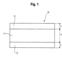
- FIG. 1 shows a cross-section of a laminate membrane 10 according to an embodiment of the present disclosure.
- the laminate membrane 10 comprises an inner layer 11 having an inner layer thickness X, a first covering layer 12 having a first covering layer thickness Y and a second covering layer 13 having a second covering layer thickness Z.
- the first covering layer 12 is disposed on one side of the inner layer 11.
- the second covering layer 13 is disposed on another side of the inner layer 11.
- the first covering layer 12 is disposed on one side of the inner layer 11, and the second covering layer 13 is disposed on the opposite side of the inner layer 11.
- laminate membrane 10 and each of the inner layer 11, first covering layer 12 and second covering layer 13 may be disc-shaped.
- the laminate membrane 10 has a through-hole H which may be a central through-hole.
- First covering layer 12 may entirely cover one side of the inner layer 11.
- Second covering layer 13 may entirely cover the other side of the inner layer 12.
- the laminate membrane 10 may be configured to have a contracted delivery configuration and an expanded deployed configuration.
- the laminate membrane 10 forms a conical shape with a smaller radial extent than in the expanded deployed configuration (see FIG. 4 ).
- the inner layer 11 provides the backbone of the laminate membrane 10 which provides structural properties of the laminate membrane 10 such as stiffness and elasticity.
- the first covering layer 12 and the second covering layer 13 are outermost surface layers of the laminate membrane 10.
- the first covering layer 12 and the second covering layer 13 dictate the properties of the outer surface of the laminate membrane 10 such as the frictional properties and surface energy.
- the first covering layer 12 and the second covering layer 13 may each be made from a lower friction material than the material from which the inner layer 11 is made.
- the materials to be compared may be formed so as to have flat surfaces, and the surface energy, surface roughness, or static coefficient of friction (relative to itself or another common surface) of these surfaces may be measured, as would be understood by the skilled person.
- the flat surfaces of each of the materials being tested may be formed by the same process (e.g. each formed by electrospinning, extrusion, film casting, dip casting, spin casting, spray deposition or vapour deposition).
- At least one of the first covering layer 12 and the second covering layer 13 are made of a material which exhibit a lower surface roughness or static coefficient of friction (measured relative to itself or another common surface) than the material from which the inner layer 11 is made of.
- the stiffness of the inner layer 11 may be greater than the stiffness of each of the first covering layer 12 and the second covering layer 13.
- the elasticity of the first covering layer 12 and/or the second covering layer 13 may be higher than or equal to the elasticity of the inner layer 11.
- the laminate membrane 10 may allow for a contracted delivery configuration with a lower radial profile without risk of permanent deformation as the first covering layer 12 and/or the second covering layer 13, which experience greater elongation during bending of the laminate membrane 10 than the inner layer 11, are better able to stretch relative to the inner layer 11.
- first covering layer 12 Various materials may be used for the inner layer 11, first covering layer 12 and the second covering layer 13.
- the inner layer 11 may consist of polyurethane (PU) and each of the first covering layer 12 and the second covering layer 13 may consist of polytetrafluoroethylene (PTFE).
- PU polyurethane
- PTFE polytetrafluoroethylene
- the inner layer 11 of PU provides high stiffness to the laminate membrane 10
- the first covering layer 12 and the second covering layer 13 of PTFE result in the outer surface of the laminate membrane 10 having low friction.
- the high stiffness may allow the laminate membrane 10 to reliably transition from the contracted delivery configuration to the expanded deployed configuration, whilst the low friction surfaces may reduce deformation during translation.
- first covering layer thickness Y and second covering layer thickness Z are the same, and the first covering layer thickness Y and the second covering layer thickness Z are each smaller than the inner layer thickness X.
- the inner layer thickness X may be between 4 to 8 ⁇ m, and the first covering layer thickness Y and the second covering layer thickness Z may be between 1 to 3 ⁇ m. In another embodiment, the inner layer thickness X may be between 6 to 10 ⁇ m, and the first covering layer thickness Y and the second covering layer thickness Z may be between 1 to 4 ⁇ m.
- the laminate membrane 10 may be manufactured by providing the inner layer 11, providing the first covering layer 12 on one side of the inner layer 11, and providing a second covering layer 13 on another side of the inner layer 11.
- Each of the inner layer 11, first covering layer 12 and the second covering layer 13 may be deposited using electrospinning.
- FIG. 2 shows a cross-section of a laminate membrane 20 according to another embodiment comprising an inner layer 21 having an inner layer thickness X', a first covering layer 22 having a first covering layer thickness Y' and a second covering layer 23 having a second covering layer thickness Z'.
- the first covering layer 22 is disposed on one side of the inner layer 21.
- the second covering layer 23 is disposed on the opposite side of the inner layer 21.
- the inner layer thickness X' may be between 4 to 8 ⁇ m, and the first covering layer thickness Y' and the second covering layer thickness Z' may be between 1 to 3 ⁇ m. In another embodiment, the inner layer thickness X' may be between 6 to 10 ⁇ m, and the first covering layer thickness Y' and the second covering layer thickness Z' may be between 1 to 4 ⁇ m.
- Laminate membrane 20 is similar to laminate membrane 10 shown in FIG. 1 , except that first covering layer 22 and second covering layer 23 also cover the outer edge surface of the inner layer 11. In particular, first covering layer 22 and second covering layer 23 also cover the curved edge surface of the inner layer 11. Hence, the first covering layer 22 and the second covering layer 23 together cover all external surfaces of the inner layer 21.
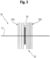
- FIG. 3 shows an embolisation device 30 according to an embodiment of the present disclosure.
- the embolisation device 30 has a longitudinally extending core 31 and a plurality of flexible bristles 32 extending outwardly from the core, the flexible bristles 32 are configured to have a contracted delivery configuration and an expanded deployed configuration in which the flexible bristles 32 extend generally radially outwardly from the core to anchor the device in a bodily lumen.
- the flexible bristles 32 may be configured to be resilient such that they are biased from their contracted delivery configuration to their expanded deployed configuration.
- the embolisation device 30 also has a laminate membrane 33 disposed on the core 31.
- the laminate membrane 33 may be any of the laminate membranes described herein.
- the laminate membrane 31 has a through-hole which allows the core 31 to pass through the laminate membrane 31.
- the laminate membrane 33 is configured to occlude flow through the bodily lumen.
- the laminate membrane 30 is positioned on the core 31 within a segment of flexible bristles 32. Some flexible bristles 32a are disposed proximally adjacent to one side of the laminate membrane 33 and some flexible bristles 32b are disposed distally adjacent to the opposite side of the laminate membrane 33.
- FIG. 4 shows the embolization device 30 in its expanded deployed configuration in a bodily lumen 40, where the flexible bristles 32 and the laminate membrane 33 are in their expanded deployed configurations. In this configuration, the laminate membrane 33 occludes flow through the bodily lumen 40. The flexible bristles 33 anchor the embolisation device 30 in the bodily lumen 40, preventing migration of the embolisation device 30.
- the orientation of the expanded laminate membrane 33 in its expanded deployed configuration and the orientation of the expanded flexible bristles 32 in the expanded deployed configuration is the same.
- both the laminate membrane 33 and the adjacent flexible bristles 32 may be deployed pointing distally or proximally.
- FIG. 5 shows the embolization device 30 in its contracted delivery configuration in a delivery catheter 50, where the flexible bristles 32 and the laminate membrane 33 are in their contracted delivery configurations.
- the flexible bristles 32 and the laminate membrane 33 are in their contracted delivery configurations, at least a portion of the laminate membrane 31 contacts the delivery catheter.
- the embolisation device 30 may be translated through the delivery catheter 50.
- the orientation of the collapsed laminate membrane 33 in its contracted delivery configuration and the orientation of the collapsed flexible bristles 32 in the contracted delivery configuration is the same.
- both the laminate membrane 33 and the adjacent flexible bristles 32 may be collapsed pointing distally or proximally.
- any of the laminate membranes as described herein may provide an embolisation device 30 in which deformation of the membrane 33 during translation through the delivery catheter 50 is minimised whilst also allowing reliable expansion of the membrane 33 and adjacent bristles 32 to their expanded deployed configurations.
- the above laminate membranes are disc-shaped, they may be of any shape such as rectangular, square or cylindrical.
- laminates according to the present disclosure are also applicable to any type of embolisation device.
- an embolisation device comprising: a laminate membrane as described herein.
- the laminate membrane is configured to have a contracted delivery configuration and an expanded deployed configuration.
- the embolisation device may comprise an embolisation coil.
- the laminate membrane may be disposed around at least part of the embolisation coil. At least a part of the laminate membrane may be disposed between adjacent turns in the embolisation coil.
- laminate membranes according to the present disclosure are also applicable to any type of medical implant, and, in particular, a medical implant with a contracted delivery configuration and an expanded deployed configuration, where the medical implant is configured to be delivered to a bodily lumen in the contracted delivery configuration.
- the laminate membranes according to the present disclosure are particularly suited to expandable stents. Using the laminate membranes of the present disclosure may reduce deformation of the membrane during translation through the delivery catheter whilst also allowing reliable expansion of the membrane to its expanded deployed configuration.
- each of the inner layer, first covering layer and the second covering layer may be made from various materials.
- the inner layer is made from a composite of polyurethane and one or more other materials.
- the inner layer is made from a polyurethane and polytetrafluoroethylene composite.
- the inner layer may be made from a copolymer of 90% 55D polyurethane and 10% silicone, by weight.
- the inner layer 11 may comprise, or consist of, condensed PTFE or fluorinated ethylene propylene (FEP).
- first covering layer and the second covering layer may be made from a composite of materials.
- the first covering layer and the second covering layer may be made from different materials from each other.
- At least on of the first covering layer and the second covering layer comprises or consists or a hydrophilic material.
- First covering layer may be made from: a hydrophobic material such as polytetrafluoroethylene and/or ultra-high molecular weight polyethylene; a hydrophilic material; and/or silicone.
- the second covering layer may be made from: a hydrophobic material such as polytetrafluoroethylene and/or ultra-high molecular weight polyethylene; a hydrophilic material; and/or silicone.
- the structural properties of the inner layer, first covering layer and the second covering layer may be varied from the above.
- the inner layer may have higher elastic recovery, tear-resistance and/or permeability than at least one of the first covering layer and the second covering layer.
- At least one of the first covering layer and the second covering layer may have lower surface energy than the inner layer.
- the inner layer, the first covering layer and the second covering layer are each single layers.
- the inner layer, the first covering layer and/or the second covering layer may each be formed of multiple sub-layers.
- the above laminate membranes may further comprise a tie-layer disposed between the inner layer and one or each of the fist covering layer and the second covering layer.
- a tie-layer may increase the adherence between the layers.
- a tie-layer may be DuPont TM Bynel ® .
- the tie-layers may be made from: modified ethylene vinyl acetate polymer; acid modified ethylene acrylate resin; anhydride modified ethylene acrylate resin; or anhydride-modified linear low-density polyethylene resin.
- the tie-layers may be made from ethylenes including acetates & acrylates thereof.
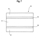
- FIG. 7 shows an exemplary embodiment of a laminate membrane 60 comprising tie-layers 64, 65.
- the laminate membrane 60 is similar to laminate membrane 10 in that in has an inner layer 61, first covering layer 62 and second covering layer 63. However, laminate membrane 60 has a first tie-layer 64 disposed between the inner layer 61 and the first covering layer 62, and a second tie-layer 65 disposed between the inner layer 61 and the second covering layer 63.
- the inner layer and the first covering layer and/or the second covering layer may be chemically or electrostatically adhered to each other.
- the layers may be formed by electrospinning, extrusion, film casting, dip casting, spin casting, spray deposition or vapour deposition.
- different layers may be formed by different methods.
- the inner layer may be formed from dip casting or spray casting.
- the first covering layer and the second covering layer may each be formed by electrospinnning onto the inner layer.
Landscapes
- Health & Medical Sciences (AREA)
- Surgery (AREA)
- Life Sciences & Earth Sciences (AREA)
- Engineering & Computer Science (AREA)
- Molecular Biology (AREA)
- Animal Behavior & Ethology (AREA)
- Vascular Medicine (AREA)
- Biomedical Technology (AREA)
- Heart & Thoracic Surgery (AREA)
- Medical Informatics (AREA)
- Reproductive Health (AREA)
- Nuclear Medicine, Radiotherapy & Molecular Imaging (AREA)
- General Health & Medical Sciences (AREA)
- Public Health (AREA)
- Veterinary Medicine (AREA)
- Mechanical Engineering (AREA)
- Materials For Medical Uses (AREA)
- Prostheses (AREA)
- Surgical Instruments (AREA)
- Laminated Bodies (AREA)
Description
- The present disclosure relates to a laminate membrane, an implant comprising the laminate membrane and a method of manufacturing the same. More specifically, the present disclosure relates to a laminate membrane having an inner layer, a first covering layer disposed on one side of the inner layer and a second covering layer disposed on another side of the inner layer.
- Embolisation devices for occluding a bodily lumen are disclosed in
WO 2014/140325 A1 andWO 2016/041961 A2 . - Such embolisation devices may have a core and a plurality of flexible bristles which extend radially outwardly from the core. The embolisation device may also be provided with a membrane having a contracted delivery configuration and an expanded deployed configuration. The contracted delivery configuration is such that the embolisation device may be loaded into a delivery catheter allowing the embolisation device to be translated through the delivery catheter for delivery to a bodily lumen.
- However, during translation through a delivery catheter, the membrane of the embolisation device may deform, for example, by folding from the initial contracted delivery configuration due to forces acting on the membrane during translation. Such forces may be exerted by the bristles of the embolisation device and/or the inner wall of the delivery catheter.
- Furthermore, due to this deformation of the membrane during translation through the delivery catheter, expansion of the membrane from the contracted delivery configuration to the expanded deployed configuration upon delivery to a bodily lumen may not occur in a reliable manner. In such cases, the membrane may not expand completely to its intended expanded deployed configuration or may exhibit undulations in its surface. In addition to this, the bristles neighbouring the membrane may also not expand in a reliable manner upon delivery. For example, the bristles may clump together such that they are not evenly distributed around the circumference of the device. These issues result in less occlusion of the bodily lumen, and, due to the uneven distribution of the bristles, also result in lower anchoring forces.
- Accordingly, there is a need for an improved embolisation device in which deformation of the membrane during translation through the delivery catheter is minimised whilst also allowing reliable expansion of the membrane and adjacent bristles to their expanded deployed configurations.
-
US 2014/058498 A1 discloses a membrane implant, said implant being implantable by endovascular methods into the vessel to be treated, wherein the membrane implant consists of an expandable stent and a membrane connected with the stent, with said membrane covering the meshes of the stent at least in a central region, wherein said membrane is provided in the form of a non-woven fabric comprising plastic fibrils, and the membrane forms an integral bond with the stent and, at 30 least partially, is of porous design. -
US 2013/184658 A1 discloses implantable medical devices for the occlusion of a bodily lumen, cavity, vessel, or organ, as well as methods for manufacturing such occlusion devices, and methods for treating a subject using the occlusion devices. The devices generally include a wire having shape memory properties and a flexible membranous material disposed about the wire. Some embodiments include a lateral fringe on the membranous material. Some embodiments include a fluid capture cup affixed to the wire. - In a first aspect, there is provided a laminate membrane for an implant, comprising: an inner layer having an inner layer thickness; a first covering layer disposed on one side of the inner layer, the first covering layer having a first covering layer thickness; and a second covering layer disposed on another side of the inner layer, the second covering layer having a second covering layer thickness; wherein the inner layer comprises, or consists of, a polyurethane and polytetrafluoroethylene composite, and, wherein at least one of the first covering layer and the second covering layer comprises, or consists of, a hydrophilic material. The laminate membrane comprises a through-hole extending through the inner layer, first covering layer and second covering layer, for passing through of a core of the embolisation device.
- In a second aspect, there is provided an embolisation device according to
claim 11. - In a third aspect, there is provided a method of manufacturing a laminate membrane according to claim 15.
- For a better understanding of the present disclosure, and to show how the same may be carried into effect, reference is made, by way of example only, to the following exemplary drawings, in which:
-
FIG. 1 shows a cross-section of a laminate membrane according to one embodiment of the present disclosure; -
FIG. 2 shows a cross-section of a laminate membrane according to another embodiment of the present disclosure; -
FIG. 3 shows an embolisation device with a laminate membrane according to an embodiment of the present disclosure; -
FIG. 4 shows the embolisation device shown inFIG. 3 in an expanded deployed configuration in a bodily lumen; -
FIG. 5 shows the embolisation device shown inFIG. 3 in a contracted delivery configuration within a delivery catheter; -
FIG. 6 shows a plan view of a laminate membrane according to embodiments of the present disclosure; and -
FIG. 7 shows a cross-section of a laminate membrane according to another embodiment of the present disclosure. -
FIG. 1 shows a cross-section of alaminate membrane 10 according to an embodiment of the present disclosure. Thelaminate membrane 10 comprises aninner layer 11 having an inner layer thickness X, afirst covering layer 12 having a first covering layer thickness Y and asecond covering layer 13 having a second covering layer thickness Z. The first coveringlayer 12 is disposed on one side of theinner layer 11. The second coveringlayer 13 is disposed on another side of theinner layer 11. In this embodiment, the first coveringlayer 12 is disposed on one side of theinner layer 11, and the second coveringlayer 13 is disposed on the opposite side of theinner layer 11. - As shown in
FIG. 6 ,laminate membrane 10 and each of theinner layer 11, first coveringlayer 12 and second coveringlayer 13 may be disc-shaped. Thelaminate membrane 10 has a through-hole H which may be a central through-hole. - First covering
layer 12 may entirely cover one side of theinner layer 11. Second coveringlayer 13 may entirely cover the other side of theinner layer 12. - The
laminate membrane 10 may be configured to have a contracted delivery configuration and an expanded deployed configuration. In the contracted delivery configuration (seeFIG. 5 ), thelaminate membrane 10 forms a conical shape with a smaller radial extent than in the expanded deployed configuration (seeFIG. 4 ). - The
inner layer 11 provides the backbone of thelaminate membrane 10 which provides structural properties of thelaminate membrane 10 such as stiffness and elasticity. In this embodiment, the first coveringlayer 12 and the second coveringlayer 13 are outermost surface layers of thelaminate membrane 10. The first coveringlayer 12 and the second coveringlayer 13 dictate the properties of the outer surface of thelaminate membrane 10 such as the frictional properties and surface energy. - The first covering
layer 12 and the second coveringlayer 13 may each be made from a lower friction material than the material from which theinner layer 11 is made. - The skilled person will be aware of many different ways of determining whether a material is a lower friction material than another material. For example, the materials to be compared may be formed so as to have flat surfaces, and the surface energy, surface roughness, or static coefficient of friction (relative to itself or another common surface) of these surfaces may be measured, as would be understood by the skilled person. The flat surfaces of each of the materials being tested may be formed by the same process (e.g. each formed by electrospinning, extrusion, film casting, dip casting, spin casting, spray deposition or vapour deposition).
- In other words, at least one of the first covering
layer 12 and the second coveringlayer 13 are made of a material which exhibit a lower surface roughness or static coefficient of friction (measured relative to itself or another common surface) than the material from which theinner layer 11 is made of. - The stiffness of the
inner layer 11 may be greater than the stiffness of each of the first coveringlayer 12 and the second coveringlayer 13. - The elasticity of the first covering
layer 12 and/or the second coveringlayer 13 may be higher than or equal to the elasticity of theinner layer 11. In such cases, thelaminate membrane 10 may allow for a contracted delivery configuration with a lower radial profile without risk of permanent deformation as the first coveringlayer 12 and/or the second coveringlayer 13, which experience greater elongation during bending of thelaminate membrane 10 than theinner layer 11, are better able to stretch relative to theinner layer 11. - Various materials may be used for the
inner layer 11, first coveringlayer 12 and the second coveringlayer 13. - In some examples not falling under the scope of the appended claims, the
inner layer 11 may consist of polyurethane (PU) and each of the first coveringlayer 12 and the second coveringlayer 13 may consist of polytetrafluoroethylene (PTFE). In this case, theinner layer 11 of PU provides high stiffness to thelaminate membrane 10, whereas the first coveringlayer 12 and the second coveringlayer 13 of PTFE result in the outer surface of thelaminate membrane 10 having low friction. The high stiffness may allow thelaminate membrane 10 to reliably transition from the contracted delivery configuration to the expanded deployed configuration, whilst the low friction surfaces may reduce deformation during translation. - In this embodiment, first covering layer thickness Y and second covering layer thickness Z are the same, and the first covering layer thickness Y and the second covering layer thickness Z are each smaller than the inner layer thickness X.
- The inner layer thickness X may be between 4 to 8 µm, and the first covering layer thickness Y and the second covering layer thickness Z may be between 1 to 3 µm. In another embodiment, the inner layer thickness X may be between 6 to 10 µm, and the first covering layer thickness Y and the second covering layer thickness Z may be between 1 to 4 µm.
- The
laminate membrane 10 may be manufactured by providing theinner layer 11, providing thefirst covering layer 12 on one side of theinner layer 11, and providing asecond covering layer 13 on another side of theinner layer 11. Each of theinner layer 11, first coveringlayer 12 and thesecond covering layer 13 may be deposited using electrospinning. -
FIG. 2 shows a cross-section of alaminate membrane 20 according to another embodiment comprising aninner layer 21 having an inner layer thickness X', afirst covering layer 22 having a first covering layer thickness Y' and asecond covering layer 23 having a second covering layer thickness Z'. Thefirst covering layer 22 is disposed on one side of theinner layer 21. Thesecond covering layer 23 is disposed on the opposite side of theinner layer 21. - The inner layer thickness X' may be between 4 to 8 µm, and the first covering layer thickness Y' and the second covering layer thickness Z' may be between 1 to 3 µm. In another embodiment, the inner layer thickness X' may be between 6 to 10 µm, and the first covering layer thickness Y' and the second covering layer thickness Z' may be between 1 to 4 µm.
-
Laminate membrane 20 is similar tolaminate membrane 10 shown inFIG. 1 , except thatfirst covering layer 22 andsecond covering layer 23 also cover the outer edge surface of theinner layer 11. In particular,first covering layer 22 andsecond covering layer 23 also cover the curved edge surface of theinner layer 11. Hence, thefirst covering layer 22 and thesecond covering layer 23 together cover all external surfaces of theinner layer 21. -
FIG. 3 shows anembolisation device 30 according to an embodiment of the present disclosure. Theembolisation device 30 has alongitudinally extending core 31 and a plurality offlexible bristles 32 extending outwardly from the core, theflexible bristles 32 are configured to have a contracted delivery configuration and an expanded deployed configuration in which theflexible bristles 32 extend generally radially outwardly from the core to anchor the device in a bodily lumen. The flexible bristles 32 may be configured to be resilient such that they are biased from their contracted delivery configuration to their expanded deployed configuration. - The
embolisation device 30 also has alaminate membrane 33 disposed on thecore 31. Thelaminate membrane 33 may be any of the laminate membranes described herein. Thelaminate membrane 31 has a through-hole which allows the core 31 to pass through thelaminate membrane 31. Thelaminate membrane 33 is configured to occlude flow through the bodily lumen. - The
laminate membrane 30 is positioned on thecore 31 within a segment offlexible bristles 32. Someflexible bristles 32a are disposed proximally adjacent to one side of thelaminate membrane 33 and someflexible bristles 32b are disposed distally adjacent to the opposite side of thelaminate membrane 33. -
FIG. 4 shows theembolization device 30 in its expanded deployed configuration in abodily lumen 40, where theflexible bristles 32 and thelaminate membrane 33 are in their expanded deployed configurations. In this configuration, thelaminate membrane 33 occludes flow through thebodily lumen 40. The flexible bristles 33 anchor theembolisation device 30 in thebodily lumen 40, preventing migration of theembolisation device 30. - The orientation of the expanded
laminate membrane 33 in its expanded deployed configuration and the orientation of the expandedflexible bristles 32 in the expanded deployed configuration is the same. For example, both thelaminate membrane 33 and the adjacentflexible bristles 32 may be deployed pointing distally or proximally. -
FIG. 5 shows theembolization device 30 in its contracted delivery configuration in adelivery catheter 50, where theflexible bristles 32 and thelaminate membrane 33 are in their contracted delivery configurations. When theflexible bristles 32 and thelaminate membrane 33 are in their contracted delivery configurations, at least a portion of thelaminate membrane 31 contacts the delivery catheter. In the contracted delivery configuration, theembolisation device 30 may be translated through thedelivery catheter 50. - The orientation of the
collapsed laminate membrane 33 in its contracted delivery configuration and the orientation of the collapsedflexible bristles 32 in the contracted delivery configuration is the same. For example, both thelaminate membrane 33 and the adjacentflexible bristles 32 may be collapsed pointing distally or proximally. - Using any of the laminate membranes as described herein may provide an
embolisation device 30 in which deformation of themembrane 33 during translation through thedelivery catheter 50 is minimised whilst also allowing reliable expansion of themembrane 33 andadjacent bristles 32 to their expanded deployed configurations. - Although the above explanation is considered to fully clarify how the present disclosure may be straight-forwardly put into effect by those skilled in the art, it is to be regarded as purely exemplary. In particular, there are a number of variations which are possible, as may be appreciated by those skilled in the art.
- For example, even though the above laminate membranes are disc-shaped, they may be of any shape such as rectangular, square or cylindrical.
- Further, even though the above laminate membranes are described in relation to an embolisation device with a core and a plurality of flexible bristles, laminates according to the present disclosure are also applicable to any type of embolisation device.
- Specifically, according to an aspect of the present disclosure, there is provided an embolisation device, comprising: a laminate membrane as described herein.
- In an embodiment, the laminate membrane is configured to have a contracted delivery configuration and an expanded deployed configuration. The embolisation device may comprise an embolisation coil. The laminate membrane may be disposed around at least part of the embolisation coil. At least a part of the laminate membrane may be disposed between adjacent turns in the embolisation coil.
- Furthermore, even though the above laminate membranes are described in relation to embolisation devices, laminate membranes according to the present disclosure are also applicable to any type of medical implant, and, in particular, a medical implant with a contracted delivery configuration and an expanded deployed configuration, where the medical implant is configured to be delivered to a bodily lumen in the contracted delivery configuration. For example, the laminate membranes according to the present disclosure are particularly suited to expandable stents. Using the laminate membranes of the present disclosure may reduce deformation of the membrane during translation through the delivery catheter whilst also allowing reliable expansion of the membrane to its expanded deployed configuration.
- Further, each of the inner layer, first covering layer and the second covering layer may be made from various materials. The inner layer is made from a composite of polyurethane and one or more other materials. In particular, the inner layer is made from a polyurethane and polytetrafluoroethylene composite. In some examples not falling under the scope of the appended claims, the inner layer may be made from a copolymer of 90% 55D polyurethane and 10% silicone, by weight. In other examples not falling under the scope of the appended claims, the
inner layer 11 may comprise, or consist of, condensed PTFE or fluorinated ethylene propylene (FEP). - Each of the first covering layer and the second covering layer may be made from a composite of materials. The first covering layer and the second covering layer may be made from different materials from each other. At least on of the first covering layer and the second covering layer comprises or consists or a hydrophilic material. First covering layer may be made from: a hydrophobic material such as polytetrafluoroethylene and/or ultra-high molecular weight polyethylene; a hydrophilic material; and/or silicone. The second covering layer may be made from: a hydrophobic material such as polytetrafluoroethylene and/or ultra-high molecular weight polyethylene; a hydrophilic material; and/or silicone.
- Further, the structural properties of the inner layer, first covering layer and the second covering layer may be varied from the above. In particular, the inner layer may have higher elastic recovery, tear-resistance and/or permeability than at least one of the first covering layer and the second covering layer. At least one of the first covering layer and the second covering layer may have lower surface energy than the inner layer.
- In the above embodiments, the inner layer, the first covering layer and the second covering layer are each single layers. However, in alternative embodiments, the inner layer, the first covering layer and/or the second covering layer may each be formed of multiple sub-layers.
- Further, the above laminate membranes may further comprise a tie-layer disposed between the inner layer and one or each of the fist covering layer and the second covering layer. Such a tie-layer may increase the adherence between the layers. As an example, such a tie-layer may be DuPont™ Bynel®. The tie-layers may be made from: modified ethylene vinyl acetate polymer; acid modified ethylene acrylate resin; anhydride modified ethylene acrylate resin; or anhydride-modified linear low-density polyethylene resin. Generally, the tie-layers may be made from ethylenes including acetates & acrylates thereof.
FIG. 7 shows an exemplary embodiment of alaminate membrane 60 comprising tie-layers laminate membrane 60 is similar tolaminate membrane 10 in that in has aninner layer 61, first coveringlayer 62 andsecond covering layer 63. However,laminate membrane 60 has a first tie-layer 64 disposed between theinner layer 61 and thefirst covering layer 62, and a second tie-layer 65 disposed between theinner layer 61 and thesecond covering layer 63. - In some embodiments, the inner layer and the first covering layer and/or the second covering layer may be chemically or electrostatically adhered to each other.
- Furthermore, even though the above manufacturing method uses an electrospinning process for forming each of the layers, various other manufacturing methods may be used. For example, the layers may be formed by electrospinning, extrusion, film casting, dip casting, spin casting, spray deposition or vapour deposition. Furthermore, different layers may be formed by different methods. For example, the inner layer may be formed from dip casting or spray casting. The first covering layer and the second covering layer may each be formed by electrospinnning onto the inner layer.
- All of the above are fully within the scope of the present disclosure, and are considered to form the basis for alternative embodiments in which one or more combinations of the above described features are applied, without limitation to the specific combinations disclosed above.
- In light of this, there will be many alternatives which implement the teaching of the present disclosure. It is expected that one skilled in the art will be able to modify and adapt the above disclosure to suit its own circumstances and requirements within the scope of the present disclosure, while retaining some or all technical effects of the same, either disclosed or derivable from the above, in light of his common general knowledge in this art.
Claims (15)
- A membrane (10, 20, 60) for an embolisation device, comprising:a though-hole (H) for passing through of a core of the embolisation device,characterised in thatthe membrane is a laminate membrane, andthe laminate membrane further comprisesan inner layer (11, 21, 61) having an inner layer thickness (x, x');a first covering layer (12, 22, 62) disposed on one side of the inner layer, the first covering layer having a first covering layer thickness (y, y'); anda second covering layer (13, 23, 63) disposed on another side of the inner layer, the second covering layer having a second covering layer thickness (z, z'); wherein the inner layer comprises, or consists of, a polyurethane and polytetrafluoroethylene composite, and, wherein at least one of the first covering layer and the second covering layer comprises, or consists of, a hydrophilic material wherein the through-hole (H) extends through the inner layer, first covering layer and second covering layer.
- The laminate membrane (10, 20, 60) of Claim 1, wherein at least one of the first covering layer (12, 22, 62) and the second covering layer (13, 23, 63) is made from a lower friction material than the material from which the inner layer (11, 21, 61) is made; and/orwherein the stiffness of the inner layer (11, 21, 61) is greater than the stiffness of at least one of the first covering layer (12, 22, 62) and the second covering layer (13, 23, 63); and/orwherein the elasticity of at least one of the first covering layer (12, 22, 62) and the second covering layer (13, 23, 63) is higher than or equal to the elasticity of the inner layer (11, 21, 61).
- The laminate membrane (10, 20, 60) of any preceding claim, wherein at least one of the first covering layer (11, 21, 61) and the second covering layer (12, 22, 62) is an outer surface layer of the laminate membrane.
- The laminate membrane (10, 20, 60) of any preceding claim, wherein the inner layer (11, 21, 61) has at least one of a higher elastic recovery, tear-resistance and permeability than at least one of the first covering layer (12, 22, 62) and the second covering layer (13, 23, 63); and/or wherein at least one of the first covering layer (12, 22, 62) and the second covering layer (13, 23, 63) has lower surface energy than the inner layer (11, 21, 61).
- The laminate membrane (10, 20, 60) of any preceding claim, wherein: the inner layer thickness (x, x') is between 6 to 10 µm, and at least one of the first covering layer thickness (y, y') and the second covering layer thickness (z, z') is between 1 to 4 µm; or
wherein: the inner layer thickness (x, x') is between 4 to 8 µm, and at least one of the first covering layer thickness (y, y') and the second covering layer thickness (z, z') is between 1 to 3 µm. - The laminate membrane (10, 20, 60) of any preceding claim, wherein a first surface of the inner layer (11, 21, 61) is in contact with a surface of the first covering layer (12, 22, 62), and wherein at least one of the first surface of the inner layer (11, 21, 61) and the surface of the first covering layer (12, 22, 62) has a texture feature configured to mechanically adhere the inner layer (11, 21, 61) and the first covering layer (12, 22, 62); and preferably wherein a second surface of the inner layer (11, 21, 61) is in contact with a surface of the second covering layer (13, 23, 63), and wherein at least one of the second surface of the inner layer (11, 21, 61) and the surface of the second covering layer (13, 23, 63) has a texture feature configured to mechanically adhere the inner layer (11, 21, 61) and the second covering layer (13, 23, 63).
- The laminate membrane (10, 20, 60) of any preceding claim, comprising at least one of a tie-layer (64) between the inner layer (11, 21, 61) and the first covering layer (12, 22, 62) and a tie-layer (65) between the inner layer (11, 21, 61) and the second covering layer (13, 23, 63).
- The laminate membrane (10, 20, 60) of any preceding claim, wherein at least one of the first covering layer thickness (y, y') and the second covering layer thickness (z, z') is less than the inner layer thickness (x, x').
- The laminate membrane (10, 20, 60) of any preceding claim, wherein at least one of the first covering layer (12, 22, 62) and the second covering layer (13, 23, 63) entirely covers the one side or the another side of the inner layer (11, 21, 61), respectively; and preferably wherein the first covering layer (12, 22, 62) and the second covering layer (13, 23, 63) together cover all external surfaces of the inner layer (11, 21, 61).
- The laminate membrane (10, 20, 60) of any preceding claim, wherein the stiffness of the inner layer (11, 21, 61) is between 0.9 to 2.5 GPa, alternatively between 1.1 to 2.3 GPa, and alternatively between 1.3 to 2.1 GPa; and/or wherein the stiffness of at least one of the first covering layer (12, 22, 62) and the second covering layer (13, 23, 63) is between 0.1 to 0.75 GPa, alternatively between 0.25 to 0.65 GPa, and alternatively between 0.4 to 0.55 GPa.
- An embolisation device (30) comprising:a core (31);a plurality of flexible bristles (32) extending outwardly from the core, the flexible bristles having a contracted delivery configuration and an expanded deployed configuration in which the flexible bristles extend radially outwardly from the core; andthe laminate membrane according to any preceding claim, the laminate membrane disposed on the core, wherein the laminate membrane is configured to have a contracted delivery configuration and an expanded deployed configuration.
- The embolisation device (30) of Claim 11, wherein the embolisation device is configured to be delivered to a bodily lumen (40) by a delivery catheter (50) when the laminate membrane (10, 20, 60) is in the contracted delivery configuration, and wherein in the contracted delivery configuration at least a portion of the laminate membrane is configured to abut an inner wall of the delivery catheter.
- The embolisation device (30) of Claim 11 or 12, wherein the laminate membrane (10, 20, 60) is disposed adjacent to at least some of the flexible bristles (32), and preferably wherein at least some of the flexible bristles are disposed on either side of the laminate membrane.
- The embolisation device (30) of Claim 13, wherein the surface energy, surface roughness, or static coefficient of friction of the at least some of the plurality of flexible bristles (32) is less than the laminate membrane (10, 20, 60).
- A method of manufacturing the laminate membrane (10, 20, 60) of any one of claims 1 to 10, comprising:providing the inner layer (11, 21, 61);providing the first covering layer (12, 22, 62) on one side of the inner layer; andproviding the second covering layer (13, 23, 63) on another side of the inner layer.
Priority Applications (1)
| Application Number | Priority Date | Filing Date | Title |
|---|---|---|---|
| EP21197948.9A EP3943022B1 (en) | 2017-05-18 | 2018-05-18 | An implant comprising a laminate membrane |
Applications Claiming Priority (2)
| Application Number | Priority Date | Filing Date | Title |
|---|---|---|---|
| GBGB1708025.0A GB201708025D0 (en) | 2017-05-18 | 2017-05-18 | A laminate membrane, an implant comprising the laminate membrane and a method of manufacturing the same |
| PCT/EP2018/063148 WO2018211091A1 (en) | 2017-05-18 | 2018-05-18 | A laminate membrane, an implant comprising the laminate membrane and a method of manufacturing the same |
Related Child Applications (2)
| Application Number | Title | Priority Date | Filing Date |
|---|---|---|---|
| EP21197948.9A Division EP3943022B1 (en) | 2017-05-18 | 2018-05-18 | An implant comprising a laminate membrane |
| EP21197948.9A Division-Into EP3943022B1 (en) | 2017-05-18 | 2018-05-18 | An implant comprising a laminate membrane |
Publications (3)
| Publication Number | Publication Date |
|---|---|
| EP3576645A1 EP3576645A1 (en) | 2019-12-11 |
| EP3576645C0 EP3576645C0 (en) | 2025-04-30 |
| EP3576645B1 true EP3576645B1 (en) | 2025-04-30 |
Family
ID=59220675
Family Applications (2)
| Application Number | Title | Priority Date | Filing Date |
|---|---|---|---|
| EP21197948.9A Active EP3943022B1 (en) | 2017-05-18 | 2018-05-18 | An implant comprising a laminate membrane |
| EP18726136.7A Active EP3576645B1 (en) | 2017-05-18 | 2018-05-18 | LAMINATE MEMBRANE, IMPLANT COMPRISING THE LAMINATE MEMBRANE AND METHOD FOR PRODUCING THE SAME |
Family Applications Before (1)
| Application Number | Title | Priority Date | Filing Date |
|---|---|---|---|
| EP21197948.9A Active EP3943022B1 (en) | 2017-05-18 | 2018-05-18 | An implant comprising a laminate membrane |
Country Status (8)
| Country | Link |
|---|---|
| US (2) | US10952738B2 (en) |
| EP (2) | EP3943022B1 (en) |
| JP (2) | JP6743313B2 (en) |
| CN (2) | CN110621238B (en) |
| AU (2) | AU2018269863B2 (en) |
| GB (1) | GB201708025D0 (en) |
| NZ (1) | NZ773746A (en) |
| WO (1) | WO2018211091A1 (en) |
Families Citing this family (3)
| Publication number | Priority date | Publication date | Assignee | Title |
|---|---|---|---|---|
| GB201708025D0 (en) | 2017-05-18 | 2017-07-05 | Clearstream Tech Ltd | A laminate membrane, an implant comprising the laminate membrane and a method of manufacturing the same |
| EP4103072B1 (en) * | 2020-05-22 | 2025-04-30 | Clearstream Technologies Limited | Embolisation devices and methods of manufacturing the same |
| WO2021244744A1 (en) * | 2020-06-04 | 2021-12-09 | Clearstream Technologies Limited | Flow restrictor for an embolization device |
Citations (1)
| Publication number | Priority date | Publication date | Assignee | Title |
|---|---|---|---|---|
| US20130184658A1 (en) * | 2012-01-13 | 2013-07-18 | W. L. Gore & Associates, Inc. | Occlusion devices and methods of their manufacture and use |
Family Cites Families (32)
| Publication number | Priority date | Publication date | Assignee | Title |
|---|---|---|---|---|
| US5333620A (en) * | 1991-10-30 | 1994-08-02 | C. R. Bard, Inc. | High performance plastic coated medical guidewire |
| US5630844A (en) * | 1995-06-07 | 1997-05-20 | Novamed Medical Products Manufacturing, Inc. | Biocompatible hydrophobic laminate with thermoplastic elastomer layer |
| US5585407A (en) | 1995-07-13 | 1996-12-17 | Minnesota Mining And Manufacturing Company | Water-based coatable compositions comprising reaction products of acrylic emulsion polymers with organoalkoxysilanes |
| US6045557A (en) * | 1995-11-10 | 2000-04-04 | Baxter International Inc. | Delivery catheter and method for positioning an intraluminal graft |
| IL125417A (en) * | 1996-02-02 | 2004-03-28 | Transvascular Inc | Apparatus for blocking flow through blood vessels |
| US7807211B2 (en) * | 1999-09-03 | 2010-10-05 | Advanced Cardiovascular Systems, Inc. | Thermal treatment of an implantable medical device |
| DE50106752D1 (en) | 2000-04-27 | 2005-08-25 | Sika Schweiz Ag Zuerich | Static mixing element and static mixer and use thereof |
| US20020084178A1 (en) * | 2000-12-19 | 2002-07-04 | Nicast Corporation Ltd. | Method and apparatus for manufacturing polymer fiber shells via electrospinning |
| US6960224B2 (en) * | 2003-01-22 | 2005-11-01 | Cardia, Inc. | Laminated sheets for use in a fully retrievable occlusion device |
| US7790273B2 (en) * | 2006-05-24 | 2010-09-07 | Nellix, Inc. | Material for creating multi-layered films and methods for making the same |
| US20080097374A1 (en) | 2006-08-07 | 2008-04-24 | Korleski Joseph E | Inflatable shaped balloons |
| JP2008119022A (en) * | 2006-11-08 | 2008-05-29 | Olympus Corp | Medical instrument and its manufacturing method |
| EP2268228A1 (en) * | 2008-04-23 | 2011-01-05 | Mardil, Inc. | Implantable anti-adhesion three layer patch |
| US9820746B2 (en) * | 2008-07-28 | 2017-11-21 | Incube Laboratories LLC | System and method for scaffolding anastomoses |
| KR20140090704A (en) * | 2009-03-10 | 2014-07-17 | 메드프린 리제너레이티브 메디컬 테크놀러지스 컴퍼니 리미티드 | Artificial dura mater and manufacturing method thereof |
| IN2012DN00525A (en) * | 2009-08-07 | 2015-06-05 | Zeus Ind Products Inc | |
| US8388645B2 (en) * | 2009-12-21 | 2013-03-05 | Boston Scientific Scimed, Inc. | Intravascular filter restraining device |
| JP5770727B2 (en) * | 2010-06-16 | 2015-08-26 | テルモ株式会社 | Manufacturing method of medical device |
| DE102011012501A1 (en) * | 2011-02-25 | 2012-08-30 | Phenox Gmbh | Implant with fiber fleece |
| US20130204234A1 (en) * | 2011-08-12 | 2013-08-08 | Edward H. Cully | Systems for the reduction of leakage around medical devices at a treatment site |
| EP2911712B1 (en) * | 2012-10-25 | 2017-11-29 | Boston Scientific Scimed, Inc. | Stent having a tacky silicone coating to prevent stent migration |
| US9770352B2 (en) * | 2013-03-14 | 2017-09-26 | W. L. Gore & Associates, Inc. | Inflatable balloon and cover |
| US10675039B2 (en) * | 2013-03-15 | 2020-06-09 | Embo Medical Limited | Embolisation systems |
| KR102333433B1 (en) * | 2013-03-15 | 2021-12-02 | 내셔널 유니버시티 오브 아일랜드, 갈웨이 | Embolisation systems |
| JP6110186B2 (en) * | 2013-04-01 | 2017-04-05 | テルモ株式会社 | Lubricant coatings and medical devices |
| EP2987464B1 (en) * | 2013-04-18 | 2018-08-22 | National University Corporation Yamagata University | Stent to be placed in bile duct and process for producing same |
| TW201506445A (en) | 2013-08-01 | 2015-02-16 | Hon Hai Prec Ind Co Ltd | Display system and display method for display system |
| WO2015189354A1 (en) * | 2014-06-13 | 2015-12-17 | Neuravi Limited | Devices for removal of acute blockages from blood vessels |
| CN106604697A (en) * | 2014-08-27 | 2017-04-26 | 阿姆尼斯治疗有限公司 | Implantable devices comprising graft membranes |
| CN111588433B (en) | 2014-09-15 | 2023-12-05 | 恩波医疗有限公司 | embolization device |
| CN107405152B (en) * | 2015-02-10 | 2021-04-09 | 波士顿科学国际有限公司 | Vascular occlusion device |
| GB201708025D0 (en) | 2017-05-18 | 2017-07-05 | Clearstream Tech Ltd | A laminate membrane, an implant comprising the laminate membrane and a method of manufacturing the same |
-
2017
- 2017-05-18 GB GBGB1708025.0A patent/GB201708025D0/en not_active Ceased
-
2018
- 2018-05-18 US US16/613,737 patent/US10952738B2/en not_active Expired - Fee Related
- 2018-05-18 CN CN201880031300.2A patent/CN110621238B/en not_active Expired - Fee Related
- 2018-05-18 EP EP21197948.9A patent/EP3943022B1/en active Active
- 2018-05-18 JP JP2019563601A patent/JP6743313B2/en not_active Expired - Fee Related
- 2018-05-18 NZ NZ773746A patent/NZ773746A/en unknown
- 2018-05-18 WO PCT/EP2018/063148 patent/WO2018211091A1/en not_active Ceased
- 2018-05-18 AU AU2018269863A patent/AU2018269863B2/en not_active Ceased
- 2018-05-18 EP EP18726136.7A patent/EP3576645B1/en active Active
- 2018-05-18 CN CN201911321427.0A patent/CN110840510B/en not_active Expired - Fee Related
-
2020
- 2020-04-16 AU AU2020202567A patent/AU2020202567B2/en not_active Ceased
- 2020-07-28 JP JP2020126929A patent/JP7137598B2/en not_active Expired - Fee Related
-
2021
- 2021-02-12 US US17/174,564 patent/US11602349B2/en active Active
Patent Citations (1)
| Publication number | Priority date | Publication date | Assignee | Title |
|---|---|---|---|---|
| US20130184658A1 (en) * | 2012-01-13 | 2013-07-18 | W. L. Gore & Associates, Inc. | Occlusion devices and methods of their manufacture and use |
Also Published As
| Publication number | Publication date |
|---|---|
| AU2018269863A1 (en) | 2019-10-31 |
| GB201708025D0 (en) | 2017-07-05 |
| AU2018269863B2 (en) | 2020-03-12 |
| CN110840510A (en) | 2020-02-28 |
| EP3576645C0 (en) | 2025-04-30 |
| NZ773746A (en) | 2023-10-27 |
| US10952738B2 (en) | 2021-03-23 |
| WO2018211091A1 (en) | 2018-11-22 |
| EP3943022C0 (en) | 2024-03-27 |
| JP6743313B2 (en) | 2020-08-19 |
| NZ758196A (en) | 2021-03-26 |
| US20200078022A1 (en) | 2020-03-12 |
| AU2020202567A1 (en) | 2020-05-07 |
| CN110840510B (en) | 2022-10-14 |
| JP2020520280A (en) | 2020-07-09 |
| CN110621238A (en) | 2019-12-27 |
| US11602349B2 (en) | 2023-03-14 |
| JP7137598B2 (en) | 2022-09-14 |
| EP3943022B1 (en) | 2024-03-27 |
| US20210161538A1 (en) | 2021-06-03 |
| CN110621238B (en) | 2020-10-16 |
| JP2020185415A (en) | 2020-11-19 |
| EP3943022A1 (en) | 2022-01-26 |
| EP3576645A1 (en) | 2019-12-11 |
| AU2020202567B2 (en) | 2021-03-11 |
Similar Documents
| Publication | Publication Date | Title |
|---|---|---|
| CA2851145C (en) | Profile reduction seal for prosthetic heart valve | |
| US11602349B2 (en) | Laminate membrane, an implant compromising the laminate membrane and a method of manufacturing the same | |
| JP6756785B2 (en) | Geometric control of bending properties in artificial heart valve leaflets | |
| JP6473089B2 (en) | Reinforcing valve | |
| US11752322B2 (en) | Cannula for intravascular blood pump | |
| US9737422B2 (en) | Stent | |
| CN113164173B (en) | Left atrial appendage implant with sealed pocket | |
| JP2024144616A (en) | Artificial valves and medical systems | |
| JP2020509836A (en) | Steering wire attachment for angle setting | |
| WO2018234454A1 (en) | Cannula for intravascular blood pump | |
| US20130103162A1 (en) | Coated stent | |
| RU2014124122A (en) | GRID | |
| JP2021535786A (en) | Releasable knots for medical device delivery | |
| JP7383052B2 (en) | Valved conduit with expandable frame | |
| NZ758196B2 (en) | A laminate membrane, an implant comprising the laminate membrane and a method of manufacturing the same | |
| CN120583917A (en) | Therapeutic treatment device with a braided strand microvalve occluder having a modified filtration coating |
Legal Events
| Date | Code | Title | Description |
|---|---|---|---|
| STAA | Information on the status of an ep patent application or granted ep patent |
Free format text: STATUS: UNKNOWN |
|
| STAA | Information on the status of an ep patent application or granted ep patent |
Free format text: STATUS: THE INTERNATIONAL PUBLICATION HAS BEEN MADE |
|
| PUAI | Public reference made under article 153(3) epc to a published international application that has entered the european phase |
Free format text: ORIGINAL CODE: 0009012 |
|
| STAA | Information on the status of an ep patent application or granted ep patent |
Free format text: STATUS: REQUEST FOR EXAMINATION WAS MADE |
|
| 17P | Request for examination filed |
Effective date: 20190903 |
|
| AK | Designated contracting states |
Kind code of ref document: A1 Designated state(s): AL AT BE BG CH CY CZ DE DK EE ES FI FR GB GR HR HU IE IS IT LI LT LU LV MC MK MT NL NO PL PT RO RS SE SI SK SM TR |
|
| AX | Request for extension of the european patent |
Extension state: BA ME |
|
| DAV | Request for validation of the european patent (deleted) | ||
| DAX | Request for extension of the european patent (deleted) | ||
| STAA | Information on the status of an ep patent application or granted ep patent |
Free format text: STATUS: EXAMINATION IS IN PROGRESS |
|
| 17Q | First examination report despatched |
Effective date: 20210825 |
|
| GRAP | Despatch of communication of intention to grant a patent |
Free format text: ORIGINAL CODE: EPIDOSNIGR1 |
|
| STAA | Information on the status of an ep patent application or granted ep patent |
Free format text: STATUS: GRANT OF PATENT IS INTENDED |
|
| RIC1 | Information provided on ipc code assigned before grant |
Ipc: B32B 7/12 20060101ALN20240813BHEP Ipc: A61B 17/00 20060101ALN20240813BHEP Ipc: B32B 27/40 20060101ALI20240813BHEP Ipc: B32B 27/32 20060101ALI20240813BHEP Ipc: B32B 27/08 20060101ALI20240813BHEP Ipc: B32B 7/022 20190101ALI20240813BHEP Ipc: B32B 3/26 20060101ALI20240813BHEP Ipc: A61B 17/12 20060101AFI20240813BHEP |
|
| INTG | Intention to grant announced |
Effective date: 20240829 |
|
| RIN1 | Information on inventor provided before grant (corrected) |
Inventor name: WHELAN, MICHAEL Inventor name: FORDE, COLIN Inventor name: BRADY, CONOR Inventor name: WALL, SEAN |
|
| GRAJ | Information related to disapproval of communication of intention to grant by the applicant or resumption of examination proceedings by the epo deleted |
Free format text: ORIGINAL CODE: EPIDOSDIGR1 |
|
| STAA | Information on the status of an ep patent application or granted ep patent |
Free format text: STATUS: EXAMINATION IS IN PROGRESS |
|
| GRAP | Despatch of communication of intention to grant a patent |
Free format text: ORIGINAL CODE: EPIDOSNIGR1 |
|
| STAA | Information on the status of an ep patent application or granted ep patent |
Free format text: STATUS: GRANT OF PATENT IS INTENDED |
|
| INTC | Intention to grant announced (deleted) | ||
| RIC1 | Information provided on ipc code assigned before grant |
Ipc: B32B 7/12 20060101ALN20241126BHEP Ipc: A61B 17/00 20060101ALN20241126BHEP Ipc: B32B 27/40 20060101ALI20241126BHEP Ipc: B32B 27/32 20060101ALI20241126BHEP Ipc: B32B 27/08 20060101ALI20241126BHEP Ipc: B32B 7/022 20190101ALI20241126BHEP Ipc: B32B 3/26 20060101ALI20241126BHEP Ipc: A61B 17/12 20060101AFI20241126BHEP |
|
| INTG | Intention to grant announced |
Effective date: 20241205 |
|
| GRAS | Grant fee paid |
Free format text: ORIGINAL CODE: EPIDOSNIGR3 |
|
| GRAA | (expected) grant |
Free format text: ORIGINAL CODE: 0009210 |
|
| STAA | Information on the status of an ep patent application or granted ep patent |
Free format text: STATUS: THE PATENT HAS BEEN GRANTED |
|
| AK | Designated contracting states |
Kind code of ref document: B1 Designated state(s): AL AT BE BG CH CY CZ DE DK EE ES FI FR GB GR HR HU IE IS IT LI LT LU LV MC MK MT NL NO PL PT RO RS SE SI SK SM TR |
|
| RAP3 | Party data changed (applicant data changed or rights of an application transferred) |
Owner name: CLEARSTREAM TECHNOLOGIES LIMITED |
|
| REG | Reference to a national code |
Ref country code: CH Ref legal event code: EP Ref country code: GB Ref legal event code: FG4D |
|
| REG | Reference to a national code |
Ref country code: IE Ref legal event code: FG4D |
|
| U01 | Request for unitary effect filed |
Effective date: 20250430 |
|
| U07 | Unitary effect registered |
Designated state(s): AT BE BG DE DK EE FI FR IT LT LU LV MT NL PT RO SE SI Effective date: 20250507 |
|
| U20 | Renewal fee for the european patent with unitary effect paid |
Year of fee payment: 8 Effective date: 20250516 |
|
| PG25 | Lapsed in a contracting state [announced via postgrant information from national office to epo] |
Ref country code: ES Free format text: LAPSE BECAUSE OF FAILURE TO SUBMIT A TRANSLATION OF THE DESCRIPTION OR TO PAY THE FEE WITHIN THE PRESCRIBED TIME-LIMIT Effective date: 20250430 |
|
| PG25 | Lapsed in a contracting state [announced via postgrant information from national office to epo] |
Ref country code: NO Free format text: LAPSE BECAUSE OF FAILURE TO SUBMIT A TRANSLATION OF THE DESCRIPTION OR TO PAY THE FEE WITHIN THE PRESCRIBED TIME-LIMIT Effective date: 20250730 Ref country code: GR Free format text: LAPSE BECAUSE OF FAILURE TO SUBMIT A TRANSLATION OF THE DESCRIPTION OR TO PAY THE FEE WITHIN THE PRESCRIBED TIME-LIMIT Effective date: 20250731 |
|
| PG25 | Lapsed in a contracting state [announced via postgrant information from national office to epo] |
Ref country code: PL Free format text: LAPSE BECAUSE OF FAILURE TO SUBMIT A TRANSLATION OF THE DESCRIPTION OR TO PAY THE FEE WITHIN THE PRESCRIBED TIME-LIMIT Effective date: 20250430 |
|
| PG25 | Lapsed in a contracting state [announced via postgrant information from national office to epo] |
Ref country code: HR Free format text: LAPSE BECAUSE OF FAILURE TO SUBMIT A TRANSLATION OF THE DESCRIPTION OR TO PAY THE FEE WITHIN THE PRESCRIBED TIME-LIMIT Effective date: 20250430 |
|
| PG25 | Lapsed in a contracting state [announced via postgrant information from national office to epo] |
Ref country code: RS Free format text: LAPSE BECAUSE OF FAILURE TO SUBMIT A TRANSLATION OF THE DESCRIPTION OR TO PAY THE FEE WITHIN THE PRESCRIBED TIME-LIMIT Effective date: 20250731 |
|
| PG25 | Lapsed in a contracting state [announced via postgrant information from national office to epo] |
Ref country code: IS Free format text: LAPSE BECAUSE OF FAILURE TO SUBMIT A TRANSLATION OF THE DESCRIPTION OR TO PAY THE FEE WITHIN THE PRESCRIBED TIME-LIMIT Effective date: 20250830 |
|
| REG | Reference to a national code |
Ref country code: CH Ref legal event code: H13 Free format text: ST27 STATUS EVENT CODE: U-0-0-H10-H13 (AS PROVIDED BY THE NATIONAL OFFICE) Effective date: 20251223 |
|
| PG25 | Lapsed in a contracting state [announced via postgrant information from national office to epo] |
Ref country code: SM Free format text: LAPSE BECAUSE OF FAILURE TO SUBMIT A TRANSLATION OF THE DESCRIPTION OR TO PAY THE FEE WITHIN THE PRESCRIBED TIME-LIMIT Effective date: 20250430 |
|
| PG25 | Lapsed in a contracting state [announced via postgrant information from national office to epo] |
Ref country code: CH Free format text: LAPSE BECAUSE OF NON-PAYMENT OF DUE FEES Effective date: 20250531 |
|
| PG25 | Lapsed in a contracting state [announced via postgrant information from national office to epo] |
Ref country code: CZ Free format text: LAPSE BECAUSE OF FAILURE TO SUBMIT A TRANSLATION OF THE DESCRIPTION OR TO PAY THE FEE WITHIN THE PRESCRIBED TIME-LIMIT Effective date: 20250430 |
|
| PG25 | Lapsed in a contracting state [announced via postgrant information from national office to epo] |
Ref country code: SK Free format text: LAPSE BECAUSE OF FAILURE TO SUBMIT A TRANSLATION OF THE DESCRIPTION OR TO PAY THE FEE WITHIN THE PRESCRIBED TIME-LIMIT Effective date: 20250430 |
|
| PG25 | Lapsed in a contracting state [announced via postgrant information from national office to epo] |
Ref country code: MC Free format text: LAPSE BECAUSE OF FAILURE TO SUBMIT A TRANSLATION OF THE DESCRIPTION OR TO PAY THE FEE WITHIN THE PRESCRIBED TIME-LIMIT Effective date: 20250430 |
|
| PLBE | No opposition filed within time limit |
Free format text: ORIGINAL CODE: 0009261 |
|
| STAA | Information on the status of an ep patent application or granted ep patent |
Free format text: STATUS: NO OPPOSITION FILED WITHIN TIME LIMIT |
|
| REG | Reference to a national code |
Ref country code: CH Ref legal event code: L10 Free format text: ST27 STATUS EVENT CODE: U-0-0-L10-L00 (AS PROVIDED BY THE NATIONAL OFFICE) Effective date: 20260311 |
|
| 26N | No opposition filed |
Effective date: 20260202 |
|
| PG25 | Lapsed in a contracting state [announced via postgrant information from national office to epo] |
Ref country code: IE Free format text: LAPSE BECAUSE OF NON-PAYMENT OF DUE FEES Effective date: 20250518 |
|
| U20 | Renewal fee for the european patent with unitary effect paid |
Year of fee payment: 9 Effective date: 20260421 |
|
| PGFP | Annual fee paid to national office [announced via postgrant information from national office to epo] |
Ref country code: GB Payment date: 20260421 Year of fee payment: 9 |
|
| PG25 | Lapsed in a contracting state [announced via postgrant information from national office to epo] |
Ref country code: CY Free format text: LAPSE BECAUSE OF FAILURE TO SUBMIT A TRANSLATION OF THE DESCRIPTION OR TO PAY THE FEE WITHIN THE PRESCRIBED TIME-LIMIT Effective date: 20250430 |