EP3576428A1 - Ultrasonic device - Google Patents
Ultrasonic device Download PDFInfo
- Publication number
- EP3576428A1 EP3576428A1 EP18744293.4A EP18744293A EP3576428A1 EP 3576428 A1 EP3576428 A1 EP 3576428A1 EP 18744293 A EP18744293 A EP 18744293A EP 3576428 A1 EP3576428 A1 EP 3576428A1
- Authority
- EP
- European Patent Office
- Prior art keywords
- factor
- ultrasonic transducer
- temperature
- detecting unit
- capacitance
- Prior art date
- Legal status (The legal status is an assumption and is not a legal conclusion. Google has not performed a legal analysis and makes no representation as to the accuracy of the status listed.)
- Granted
Links
Images






Classifications
-
- G—PHYSICS
- G01—MEASURING; TESTING
- G01H—MEASUREMENT OF MECHANICAL VIBRATIONS OR ULTRASONIC, SONIC OR INFRASONIC WAVES
- G01H3/00—Measuring characteristics of vibrations by using a detector in a fluid
- G01H3/04—Frequency
-
- G—PHYSICS
- G01—MEASURING; TESTING
- G01S—RADIO DIRECTION-FINDING; RADIO NAVIGATION; DETERMINING DISTANCE OR VELOCITY BY USE OF RADIO WAVES; LOCATING OR PRESENCE-DETECTING BY USE OF THE REFLECTION OR RERADIATION OF RADIO WAVES; ANALOGOUS ARRANGEMENTS USING OTHER WAVES
- G01S7/00—Details of systems according to groups G01S13/00, G01S15/00, G01S17/00
- G01S7/52—Details of systems according to groups G01S13/00, G01S15/00, G01S17/00 of systems according to group G01S15/00
- G01S7/52004—Means for monitoring or calibrating
-
- G—PHYSICS
- G01—MEASURING; TESTING
- G01H—MEASUREMENT OF MECHANICAL VIBRATIONS OR ULTRASONIC, SONIC OR INFRASONIC WAVES
- G01H13/00—Measuring resonant frequency
-
- G—PHYSICS
- G01—MEASURING; TESTING
- G01S—RADIO DIRECTION-FINDING; RADIO NAVIGATION; DETERMINING DISTANCE OR VELOCITY BY USE OF RADIO WAVES; LOCATING OR PRESENCE-DETECTING BY USE OF THE REFLECTION OR RERADIATION OF RADIO WAVES; ANALOGOUS ARRANGEMENTS USING OTHER WAVES
- G01S7/00—Details of systems according to groups G01S13/00, G01S15/00, G01S17/00
- G01S7/52—Details of systems according to groups G01S13/00, G01S15/00, G01S17/00 of systems according to group G01S15/00
- G01S7/521—Constructional features
-
- H—ELECTRICITY
- H04—ELECTRIC COMMUNICATION TECHNIQUE
- H04B—TRANSMISSION
- H04B1/00—Details of transmission systems, not covered by a single one of groups H04B3/00 - H04B13/00; Details of transmission systems not characterised by the medium used for transmission
- H04B1/06—Receivers
- H04B1/16—Circuits
- H04B1/26—Circuits for superheterodyne receivers
-
- H—ELECTRICITY
- H04—ELECTRIC COMMUNICATION TECHNIQUE
- H04B—TRANSMISSION
- H04B11/00—Transmission systems employing ultrasonic, sonic or infrasonic waves
-
- H—ELECTRICITY
- H04—ELECTRIC COMMUNICATION TECHNIQUE
- H04R—LOUDSPEAKERS, MICROPHONES, GRAMOPHONE PICK-UPS OR LIKE ACOUSTIC ELECTROMECHANICAL TRANSDUCERS; ELECTRIC HEARING AIDS; PUBLIC ADDRESS SYSTEMS
- H04R3/00—Circuits for transducers
-
- G—PHYSICS
- G01—MEASURING; TESTING
- G01S—RADIO DIRECTION-FINDING; RADIO NAVIGATION; DETERMINING DISTANCE OR VELOCITY BY USE OF RADIO WAVES; LOCATING OR PRESENCE-DETECTING BY USE OF THE REFLECTION OR RERADIATION OF RADIO WAVES; ANALOGOUS ARRANGEMENTS USING OTHER WAVES
- G01S15/00—Systems using the reflection or reradiation of acoustic waves, e.g. sonar systems
- G01S15/88—Sonar systems specially adapted for specific applications
- G01S15/93—Sonar systems specially adapted for specific applications for anti-collision purposes
- G01S15/931—Sonar systems specially adapted for specific applications for anti-collision purposes of land vehicles
-
- G—PHYSICS
- G01—MEASURING; TESTING
- G01S—RADIO DIRECTION-FINDING; RADIO NAVIGATION; DETERMINING DISTANCE OR VELOCITY BY USE OF RADIO WAVES; LOCATING OR PRESENCE-DETECTING BY USE OF THE REFLECTION OR RERADIATION OF RADIO WAVES; ANALOGOUS ARRANGEMENTS USING OTHER WAVES
- G01S7/00—Details of systems according to groups G01S13/00, G01S15/00, G01S17/00
- G01S7/52—Details of systems according to groups G01S13/00, G01S15/00, G01S17/00 of systems according to group G01S15/00
- G01S7/52004—Means for monitoring or calibrating
- G01S2007/52009—Means for monitoring or calibrating of sensor obstruction, e.g. dirt- or ice-coating
Definitions
- the present invention relates to an ultrasonic apparatus, and particularly relates to an ultrasonic apparatus capable of detecting anomalies of an ultrasonic transducer included therein.
- Ultrasonic apparatuses are used in practice, in which an ultrasonic transducer transmits ultrasonic waves, receives reflected waves from an object to be detected, and thereby measures, for example, a distance to the object to be detected.
- Patent Document 1 discloses an ultrasonic sensor that is capable of detecting adhesion of a foreign substance, such as mud. This ultrasonic sensor detects the resonant frequency of an ultrasonic vibrator, monitors and compares the resonant frequency with the natural frequency, and thereby detects an anomaly in the operation of the ultrasonic vibrator.
- Patent Document 1 Japanese Patent No. 2998232
- the resonant frequency changes as the temperature changes. Therefore, with an anomaly detecting method which involves using a measured resonant frequency alone, it may be difficult to distinguish between an anomaly and a temperature change.
- An object of the present invention is to provide an ultrasonic apparatus that is capable of accurately detecting anomalies of an ultrasonic transducer.
- An ultrasonic apparatus includes an ultrasonic transducer, a driving circuit, a receiving circuit, a frequency detecting unit, a storage unit, a temperature detecting unit, and a determining unit.
- the driving circuit causes the ultrasonic transducer to transmit sonic waves.
- the receiving circuit receives sonic waves received by the ultrasonic transducer.
- the frequency detecting unit detects a resonant frequency of the ultrasonic transducer.
- the storage unit stores a resonant frequency of the ultrasonic transducer at a predetermined temperature.
- the determining unit determines an anomaly of the ultrasonic transducer on the basis of a temperature detected by the temperature detecting unit, the resonant frequency stored in the storage unit, and the resonant frequency detected by the frequency detecting unit.
- An ultrasonic apparatus includes an ultrasonic transducer; a driving circuit configured to cause the ultrasonic transducer to transmit sonic waves; a receiving circuit configured to receive sonic waves received by the ultrasonic transducer; a Q-factor detecting unit configured to detect a Q factor of the ultrasonic transducer; a storage unit configured to store a Q factor of the ultrasonic transducer at a predetermined temperature; a temperature detecting unit; and a determining unit configured to determine an anomaly of the ultrasonic transducer on the basis of a temperature detected by the temperature detecting unit, the Q factor stored in the storage unit, and the Q factor detected by the Q-factor detecting unit.
- An ultrasonic apparatus includes an ultrasonic transducer; a driving circuit configured to cause the ultrasonic transducer to transmit sonic waves; a receiving circuit configured to receive sonic waves received by the ultrasonic transducer; a frequency detecting unit configured to detect a resonant frequency of the ultrasonic transducer; a first storage unit configured to store a resonant frequency of the ultrasonic transducer at a predetermined temperature; a Q-factor detecting unit configured to detect a Q factor of the ultrasonic transducer; a second storage unit configured to store a Q factor of the ultrasonic transducer at the predetermined temperature; a temperature detecting unit; and a determining unit configured to determine an anomaly of the ultrasonic transducer on the basis of a temperature detected by the temperature detecting unit, the resonant frequency stored in the first storage unit, the resonant frequency detected by the frequency detecting unit, the Q factor stored in the second storage unit, and the Q factor detected
- the determining unit preferably includes a resonant frequency estimating unit configured to estimate a resonant frequency at the temperature detected by the temperature detecting unit, on the basis of the resonant frequency stored in the first storage unit; a first determination processing unit configured to determine whether the resonant frequency detected by the frequency detecting unit is normal, on the basis of the resonant frequency estimated by the resonant frequency estimating unit; a Q-factor estimating unit configured to estimate a Q factor at the temperature detected by the temperature detecting unit, on the basis of the Q factor stored in the second storage unit; and a second determination processing unit configured to determine whether the Q factor detected by the Q-factor detecting unit is normal, on the basis of the Q factor estimated by the Q-factor estimating unit.
- the determining unit preferably includes a resonant frequency estimating unit configured to estimate a resonant frequency at the temperature detected by the temperature detecting unit, on the basis of the resonant frequency stored in the first storage unit; a Q-factor estimating unit configured to estimate a Q factor at the temperature detected by the temperature detecting unit, on the basis of the Q factor stored in the second storage unit; and an anomaly determining unit configured to determine whether the ultrasonic transducer is normal, on the basis of a combination of the resonant frequency estimated by the resonant frequency estimating unit and the Q factor estimated by the Q-factor estimating unit.
- the temperature detecting unit preferably includes a capacitance detecting unit configured to detect a capacitance of the ultrasonic transducer; a capacitance storage unit configured to store a capacitance of the ultrasonic transducer at the predetermined temperature; and a temperature estimating unit configured to estimate a temperature on the basis of the capacitance detected by the capacitance detecting unit and the capacitance stored by the capacitance storage unit.
- An ultrasonic apparatus includes an ultrasonic transducer; a driving circuit configured to cause the ultrasonic transducer to transmit sonic waves; a receiving circuit configured to receive sonic waves received by the ultrasonic transducer; a Q-factor detecting unit configured to detect a Q factor of the ultrasonic transducer; a storage unit configured to store a Q factor of the ultrasonic transducer at a predetermined temperature; a capacitance detecting unit configured to detect a capacitance of the ultrasonic transducer; a capacitance storage unit configured to store a capacitance of the ultrasonic transducer at the predetermined temperature; and a determining unit configured to determine an anomaly of the ultrasonic transducer on the basis of the capacitance detected by the capacitance detecting unit, the Q factor stored in the storage unit, and the Q factor detected by the Q-factor detecting unit.
- An ultrasonic apparatus includes an ultrasonic transducer; a driving circuit configured to cause the ultrasonic transducer to transmit sonic waves; a receiving circuit configured to receive sonic waves received by the ultrasonic transducer; a frequency detecting unit configured to detect a resonant frequency of the ultrasonic transducer; a storage unit configured to store a resonant frequency of the ultrasonic transducer at a predetermined temperature; a capacitance detecting unit configured to detect a capacitance of the ultrasonic transducer; a capacitance storage unit configured to store a capacitance of the ultrasonic transducer at the predetermined temperature; and a determining unit configured to determine an anomaly of the ultrasonic transducer on the basis of the capacitance detected by the capacitance detecting unit, the resonant frequency stored in the storage unit, and the resonant frequency detected by the frequency detecting unit.
- the present invention enables accurate detection of anomalies of the ultrasonic transducer.
- Fig. 1 is a schematic block diagram illustrating a configuration of an ultrasonic apparatus including an ultrasonic transducer.
- An ultrasonic apparatus 1 includes an ultrasonic transducer 100, a microprocessor 101, a memory 102, a detecting circuit 103, a driving circuit 104, a power supply 105, a receiving circuit 106, and an anomaly detector 110.
- the microprocessor 101 reads data stored in the memory 102 and outputs, to the driving circuit 104, a control signal suitable for driving the ultrasonic transducer 100.
- the power supply 105 outputs, for example, a direct-current voltage of 12 V to the driving circuit 104.
- the driving circuit 104 generates an alternating-current voltage from the direct-current voltage on the basis of the control signal output from the microprocessor 101.
- the alternating-current voltage is boosted, as appropriate, by an amplifying circuit (not shown) and supplied to the ultrasonic transducer 100.
- the ultrasonic transducer 100 is driven, and ultrasonic waves are transmitted from the ultrasonic transducer 100, for example, into the air.
- the ultrasonic apparatus 1 When the ultrasonic transducer 100 receives reflected waves from a target, a receive signal generated in the ultrasonic transducer 100 is transmitted as a voltage value to the receiving circuit 106, further transmitted through the detecting circuit 103, and input to the microprocessor 101. The microprocessor 101 thus acquires information about the presence and movement of the target.
- the ultrasonic apparatus 1 can be used, for example, as an ultrasonic sensor mounted on a vehicle.
- Fig. 2 is a cross-sectional view of the ultrasonic transducer 100.
- the configuration of the ultrasonic transducer disclosed in Fig. 2 is merely an example. Even when an ultrasonic transducer having a different configuration is used, the ultrasonic apparatus of the present embodiment can detect anomalies of the ultrasonic transducer.
- the ultrasonic transducer 100 illustrated in Fig. 2 includes a piezoelectric element 50, a case 60, a sound absorber 63, and terminals 80 and 81.
- the case 60 has a cylindrical shape with a bottom.
- the case 60 is made of, for example, light-weight aluminum with high elasticity.
- the case 60 is made, for example, by an aluminum forging or cutting process.
- the case 60 includes a disk-shaped bottom portion 62 and a cylindrical tubular portion 61 disposed along the periphery of the bottom portion 62.
- the piezoelectric element 50 is made of, for example, PZT ceramic.
- the piezoelectric element 50 is disposed on the inner surface of the bottom portion 62 and bonded thereto with an adhesive. While the ultrasonic transducer 100 is being driven, the piezoelectric element 50 vibrates in bending directions together with the bottom portion 62.
- the inner space of the case 60 is filled with resin 71.
- the sound absorber 63 is formed by a molded body of sponge material or the like, and is interposed between the resin 71 and a portion 72 for accommodating the piezoelectric element 50. The sound absorber 63 is opposite, and at a distance from, the piezoelectric element 50.
- the piezoelectric element 50 has two electrodes 51 and 52.
- the terminal 80 is electrically connected to the electrode 52, with a wire and the case 60 interposed therebetween.
- the terminal 81 is electrically connected to the electrode 51, with a wire interposed therebetween.
- the ultrasonic transducer 100 illustrated in Fig. 1 may be a two-terminal transducer, such as that illustrated in Fig. 2 , or may be a three-terminal transducer with GND and transmitting and receiving terminals.
- Fig. 3 is a block diagram illustrating a configuration of an ultrasonic apparatus according to a first embodiment.
- the ultrasonic apparatus of the first embodiment includes the ultrasonic transducer 100, the driving circuit 104, the receiving circuit 106, and the anomaly detector 110.
- the anomaly detector 110 includes a frequency detecting unit 114, a frequency storage unit 118, a frequency estimating unit 116, a temperature detecting unit 112, and an anomaly determining unit 119.
- the driving circuit 104 outputs a driving signal in such a manner as to cause the ultrasonic transducer 100 to transmit sonic waves.
- the receiving circuit 106 receives sonic waves received by the ultrasonic transducer 100.
- the frequency detecting unit 114 detects a resonant frequency fm of the ultrasonic transducer 100.
- the frequency storage unit 118 stores the resonant frequency fm of the ultrasonic transducer 100 at a predetermined temperature. For example, the resonant frequency fm detected by the frequency detecting unit 114 when, in the process of producing ultrasonic apparatuses at the factory, the ultrasonic transducer 100 is resonated in an atmosphere of predetermined temperature, is stored as an initial value fini in the frequency storage unit 118.
- the frequency detecting unit 114 and the temperature detecting unit 112 of any known types may be used.
- the frequency detecting unit 114 may be a circuit that measures a resonant frequency from a reverberation frequency, as described for example in Japanese Unexamined Patent Application Publication No. 2015-10888 .
- the temperature detecting unit 112 may be a thermo-sensitive element, such as a thermistor, or may be configured to receive temperature information from an external temperature sensor mounted, for example, on a vehicle.
- Fig. 4 is a diagram for explaining a first example of how the frequency estimating unit 116 estimates a frequency fc.
- resonant frequencies (fini1, fini2, fini3, fini4, and fini5) are measured at given temperatures (T1, T2, T3, T4, and T5) when the ultrasonic transducer 100 in the factory default state is known to have no anomaly.
- T1, T2, T3, T4, and T5 There may be either one or a plurality of temperature points.
- the measured values at measurement points P1 to P5 are stored in the frequency storage unit 118. From the frequencies stored, the frequency estimating unit 116 determines a temperature-resonant frequency relation fstd for each individual ultrasonic transducer.
- the temperature-resonant frequency relation can be calculated, for example, by storing table data of temperatures and resonant frequencies, and linearly interpolating the stored data.
- the relation may be mathematically expressed, for example, by a linear, quadratic, or polynomial expression, and coefficients in the mathematical expression may be determined from the measurement points P1 to P5.
- the frequency estimating unit 116 determines a value corresponding to a temperature Tm obtained from the temperature detecting unit 112 during use. The frequency estimating unit 116 thus estimates the estimated resonant frequency fc.
- the temperature characteristic data may be measured, as illustrated in Fig. 4 , for each individual ultrasonic transducer so that the data can be used to determine the estimated resonant frequency fc. It takes time, however, to measure and record the temperature characteristic data for each individual ultrasonic transducer. Therefore, it is more realistic to perform a second example (described below) in which the initial value fini at a standard temperature Tstd is measured and recorded for each individual transducer, and common standard data is used to compensate for a frequency shift ⁇ f associated with a change in temperature characteristic.
- Fig. 5 is a diagram for explaining the second example of how the frequency estimating unit 116 estimates the frequency fc.
- An ultrasonic transducer's temperature-resonant frequency characteristic (forg in Fig. 5 ), used in common by a plurality of ultrasonic apparatuses, is stored in the frequency estimating unit 116.
- the temperature-resonant frequency characteristic (forg) may be stored as a function (mathematical expression) of temperature, or may be stored as a data table like a map.
- the shift ⁇ f between the resonant frequency fini at the temperature Tstd, corresponding to each individual ultrasonic transducer 100, and the temperature-resonant frequency characteristic (forg), is calculated.
- the frequency shift ⁇ f is a shift resulting from an individual difference.
- the temperature-resonant frequency characteristic (forg) is shifted by ⁇ f to determine the temperature-resonant frequency characteristic (fstd).
- the frequency estimating unit 116 determines a value corresponding to the temperature Tm obtained from the temperature detecting unit 112 during use. The frequency estimating unit 116 thus estimates the estimated resonant frequency fc.
- a difference ⁇ f1 between a resonant frequency corresponding to the predetermined temperature Tstd and a resonant frequency at the temperature Tm in the temperature-resonant frequency characteristic (forg) may be calculated and added to fini to determine fc.
- the frequency estimating unit 116 upon receiving the current measured temperature Tm from the temperature detecting unit 112, the frequency estimating unit 116 outputs the estimated resonant frequency fc. Note that although fini stored in the frequency storage unit 118 is transmitted to the frequency estimating unit 116 in Fig. 3 , fstd shown in Fig. 4 and Fig. 5 may be computed and stored in the frequency storage unit 118 in advance and referenced by the frequency estimating unit 116.
- the frequency estimating unit 116 estimates the frequency estimate fc at the temperature Tm on the basis of the temperature Tm and the initial value fini, and the anomaly determining unit 119 compares the frequency estimate fc with the resonant frequency fm, which is a measured value, to determine whether the measured value is anomalous. For example, the anomaly determining unit 119 determines a positive-side threshold f(+) and a negative-side threshold f(-), with the frequency estimate fc at the center.
- the anomaly determining unit 119 determines that the measured value is normal, and if not satisfied, the anomaly determining unit 119 determines that the measured value is anomalous.
- Patent Document 1 detects anomalies on the basis of changes in frequency, but the frequency also changes with temperature.
- anomalies such as adhesion of a foreign substance (e.g., water or mud)
- the first embodiment provides the temperature detecting unit 112, in addition to the frequency detecting unit 114, so that a change in frequency at a detected temperature is reflected in a determination threshold. This enables determination as to whether the change in frequency is caused by a temperature change or by an anomaly.
- a resonant frequency is used as a parameter to determine an anomaly in the first embodiment, but a Q factor is used in a second embodiment.
- the Q factor is an index generally used as a value "quality factor (Q)" representing the degree of sharpness, that is, how sharp the resonance peak of the resonant circuit is.
- Q quality factor
- Fig. 6 is a block diagram illustrating a configuration of an ultrasonic apparatus according to the second embodiment.
- the ultrasonic apparatus according to the second embodiment includes the ultrasonic transducer 100, the driving circuit 104, the receiving circuit 106, and an anomaly detector 210.
- the Q-factor detecting unit 214 detects a Q factor Qm of the ultrasonic transducer 100.
- the Q-factor storage unit 218 stores the Q factor Qm of the ultrasonic transducer 100 at a predetermined temperature.
- the Q factor Qm detected by the Q-factor detecting unit 214 when, in the process of producing ultrasonic apparatuses at the factory, the ultrasonic transducer 100 is vibrated in an atmosphere of predetermined temperature is stored as an initial value Qini in the Q-factor storage unit 218.
- the Q-factor detecting unit 214 of any known type may be used.
- the Q-factor detecting unit 214 measures the Q factor from the attenuation curve of reverberation frequency as described, for example, in Japanese Unexamined Patent Application Publication No. 2015-10888 .
- Fig. 7 is a diagram for explaining a first example of how the Q-factor estimating unit 216 estimates a Q factor Qc.
- Q factors Qini1, Qini2, Qini3, Qini4, and Qini5 are measured at given temperatures (T1, T2, T3, T4, and T5) when the ultrasonic transducer 100 in the factory default state is known to have no anomaly. There may be either one or a plurality of temperature points.
- the measured values at measurement points P11 to P15 are stored in the Q-factor storage unit 218. From the Q factors stored, the Q-factor estimating unit 216 determines a temperature-Q factor relation for each individual ultrasonic transducer.
- the temperature-Q factor relation can be calculated, for example, by storing table data of temperatures and Q factors, and linearly interpolating the stored data.
- the relation may be mathematically expressed, for example, by a linear, quadratic, or polynomial expression, and coefficients in the mathematical expression may be determined from the measurement points P11 to P15.
- the Q-factor estimating unit 216 determines a value corresponding to the temperature Tm obtained from the temperature detecting unit 112 during use. The Q-factor estimating unit 216 thus estimates the estimated Q factor Qc.
- the temperature characteristic data may be measured, as illustrated in Fig. 7 , for each individual ultrasonic transducer so that the data can be used to determine the estimated Q factor Qc. It takes time, however, to measure and record the temperature characteristic data for each individual ultrasonic transducer. Therefore, it is more realistic to perform a second example (described below) in which the initial value Qini at the standard temperature Tstd is measured and recorded for each individual transducer, and common data is used to compensate for a Q factor shift ⁇ Q associated with a change in temperature characteristic.
- Fig. 8 is a diagram for explaining the second example of how the Q-factor estimating unit 216 estimates the Q factor Qc.
- An ultrasonic transducer's temperature-Q factor characteristic (Qorg) used in common by a plurality of ultrasonic apparatuses, is stored in the Q-factor estimating unit 216.
- the temperature-Q factor characteristic (Qorg) may be stored as a function (mathematical expression) of temperature, or may be stored as a data table like a map.
- the Q factor shift ⁇ Q between the Q factor Qini at the temperature Tstd, corresponding to each individual ultrasonic transducer 100, and the temperature-Q factor characteristic (Qorg), is calculated.
- the Q factor shift ⁇ Q is a shift resulting from an individual difference.
- the temperature-Q factor characteristic (Qorg) is shifted by ⁇ Q to determine the temperature-Q factor characteristic (Qstd).
- the Q-factor estimating unit 216 determines a value corresponding to the temperature Tm obtained from the temperature detecting unit 112 during use. The Q-factor estimating unit 216 thus estimates the estimated Q factor Qc.
- a difference ⁇ Q1 between a Q factor corresponding to the predetermined temperature Tstd and a Q factor at the temperature Tm in the temperature-Q factor characteristic (Qorg) may be calculated and added to Qini to determine Qc.
- the Q-factor estimating unit 216 Upon receiving the current measured temperature Tm from the temperature detecting unit 112, the Q-factor estimating unit 216 outputs the estimated Q factor Qc. Note that although Qini stored in the Q-factor storage unit 218 is transmitted to the Q-factor estimating unit 216 in Fig. 3 , Qstd shown in Fig. 7 and Fig. 8 may be computed and stored in the Q-factor storage unit 218 in advance and referenced by the Q-factor estimating unit 216.
- the anomaly determining unit 219 determines an anomaly of the ultrasonic transducer 100 on the basis of the temperature Tm detected by the temperature detecting unit 112, the Q factor Qini stored in the Q-factor storage unit 218, and the Q factor Qm detected by the Q-factor detecting unit 214. The anomaly determining unit 219 then outputs a signal SR2 representing the determination result.
- the Q-factor estimating unit 216 estimates the Q factor estimate Qc at the temperature Tm on the basis of the temperature Tm and the initial value Qini, and the anomaly determining unit 219 compares the frequency estimate Qc with Qm, which is a measured value, to determine whether the measured value is anomalous. For example, the anomaly determining unit 219 determines a positive-side threshold Q(+) and a negative-side threshold Q(-), with the Q factor estimate Qc at the center. Then, if Q(-) ⁇ Qm ⁇ Q(+) is satisfied, the anomaly determining unit 219 determines that the measured value is normal, and if not satisfied, the anomaly determining unit 219 determines that the measured value is anomalous.
- the ultrasonic apparatus performs temperature compensation of the Q factor, and thus can accurately detect anomalies of the ultrasonic transducer. Anomaly detection which involves using Q factors alone has not been conventionally performed. It can therefore be expected that previously undetectable anomalies will be detected.
- Fig. 9 is a graph showing a relation between adhesion of water droplets and change in resonant frequency.
- Fig. 10 is a graph showing a relation between adhesion of water droplets and change in Q factor.
- Fig. 11 is a graph showing a relation between adhesion of mud and change in resonant frequency.
- Fig. 12 is a graph showing a relation between adhesion of mud and change in Q factor.
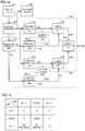
- Fig. 13 is a flowchart for explaining a determination process performed in the third embodiment.
- an anomaly detector according to the third embodiment stores an initial resonant frequency and an initial Q factor in storage units.
- the temperature Tm is measured in step S2, and the resonant frequency fc and the Q factor Qc at the current temperature Tm are estimated in step S3.
- step S4 the current resonant frequency fm and the current Q factor Qm are measured in step S4.
- step S6 If DQ > DQth holds in step S6 (YES in S6), the process proceeds to step S7, where it is determined that adhesion of mud to the entire resonating surface (or bottom portion 62 in Fig. 2 ) of the ultrasonic transducer 100 is possible. If DC > DQth does not hold (NO in S6), the process proceeds to step S8, where it is determined that adhesion of water to the resonating surface or adhesion of dried mud is possible.
- step S5 If Df > Dfth does not hold in step S5 (NO in S5), the process proceeds from step S5 to step S9, where a determination is made as to whether the drop DQ in Q factor is larger than the determination threshold DQth.
- step S9 If DQ > DQth holds in step S9 (YES in S9), the process proceeds to step S10, where it is determined that adhesion of mud to at least 1/2 of the resonating surface of the ultrasonic transducer 100 is possible. On the other hand, if DQ > DQth does not hold (NO in S9), the process proceeds to step S11, where it is determined that adhesion of water to the resonating surface is unlikely, and that mud adheres to 1/2 or less of the resonating surface.
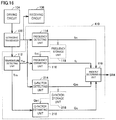
- Fig. 14 is a block diagram illustrating a configuration of an ultrasonic apparatus according to the third embodiment.
- the ultrasonic apparatus according to the first embodiment includes the ultrasonic transducer 100, the driving circuit 104, the receiving circuit 106, and an anomaly detector 310.
- the anomaly detector 310 further includes the Q-factor detecting unit 214, the Q-factor storage unit 218, the Q-factor estimating unit 216, and the anomaly determining unit 219.
- the anomaly detector 310 further includes an anomaly determining unit 319.
- the anomaly determining unit 319 forms a determining section 320 together with the anomaly determining units 119 and 219.
- the determining section 320 determines an anomaly of the ultrasonic transducer 100 on the basis of the temperature Tm detected by the temperature detecting unit 112, the resonant frequency fini stored in the frequency storage unit 118, the resonant frequency fm detected by the frequency detecting unit 114, the Q factor Qini stored in the Q-factor storage unit 218, and the Q factor Qm detected by the Q-factor detecting unit 214.
- the anomaly determining unit 319 comprehensively determines the anomaly state.
- the anomaly determining unit 319 is capable of determining whether the anomaly state is either adhesion of water, or freezing or adhesion of mud.
- f(+) means that fm is higher than the positive-side threshold f(+), and "f(-)” means that fm is lower than the negative-side threshold f(-).
- Q(+) means that Qm is larger than the positive-side threshold Q(+)
- Q(-) means that Qm is smaller than the negative-side threshold Q(-).
- the anomaly determining unit 319 If the signal SR1 corresponds to "f(OK)" and the signal SR2 corresponds to "Q(OK)", the anomaly determining unit 319 outputs "PASS" as a determination result SR3. The output "PASS" indicates that the ultrasonic transducer 100 is normal.
- the anomaly determining unit 319 outputs "M2" as the determination result SR3.
- the output "M2" indicates possible adhesion of ice or mud to the ultrasonic transducer 100.
- the anomaly determining unit 319 outputs "M1" as the determination result SR3.
- the output "M1" indicates possible adhesion of water to the ultrasonic transducer 100.
- the ultrasonic apparatus of the third embodiment is capable of making a detail estimation of the anomaly state of the ultrasonic transducer 100. That is, the anomaly can be identified either as adhesion of water or as adhesion or freezing of mud, depending on the combination of frequency and Q factor. This is applicable, for example, to classification of higher-precision control and repair operations.
- a fourth embodiment is similar to the third embodiment, but differs therefrom in determination performed by the anomaly determining unit.
- Fig. 16 is a block diagram illustrating a configuration of an ultrasonic apparatus according to the fourth embodiment.
- the ultrasonic apparatus of the fourth embodiment includes the ultrasonic transducer 100, the driving circuit 104, the receiving circuit 106, and an anomaly detector 410.
- the anomaly detector 410 includes the temperature detecting unit 112, the frequency detecting unit 114, the frequency storage unit 118, the frequency estimating unit 116, the Q-factor detecting unit 214, the Q-factor storage unit 218, the Q-factor estimating unit 216, the temperature detecting unit 112, and an anomaly determining unit 419.
- the temperature detecting unit 112, the frequency detecting unit 114, the frequency storage unit 118, and the frequency estimating unit 116 are the same as those described in the first embodiment ( Fig. 3 ).
- the Q-factor detecting unit 214, the Q-factor storage unit 218, and the Q-factor estimating unit 216 are the same as those described in the second embodiment ( Fig. 6 ). Therefore, the description of these components will not be repeated here.
- the anomaly determining unit 419 determines an anomaly of the ultrasonic transducer 100 on the basis of the resonant frequency fc estimated by the frequency estimating unit 116, the resonant frequency fm detected by the frequency detecting unit 114, the Q factor Qc estimated by the Q-factor estimating unit 216, and the Q factor Qm detected by the Q-factor detecting unit 214.
- Fig. 17 is a diagram for explaining a determination process performed by the anomaly determining unit 419.
- the anomaly determining unit 419 comprehensively determines an anomaly from the following four values: the measured and estimated resonant frequencies, and the measured and estimated Q factors.
- the anomaly determining unit 419 determines whether an anomaly occurs on the basis of whether coordinates Pm(Qm, fm) are in a PASS region centered at coordinates P(Qc, fc) in the Q-f plane.
- detailed setting of regions corresponding to the determination results PASS, M1, M2, and F can be made in accordance with, for example, actual experimental results.
- the fourth embodiment is configured similarly to the third embodiment, but differs therefrom in that instead of combining the results individually determined for the resonant frequency and the Q factor, a determination can be made at a time on the basis of the combination of the resonant frequency and the Q factor which are in a combined state from the beginning.
- a high-precision determination can be made with efficiency.
- a temperature sensor of any of various known types is used as the temperature detecting unit 112.
- the temperature detecting unit 112 performs temperature estimation by detecting a change in the capacitance of the piezoelectric element of the ultrasonic transducer 100.
- this temperature detecting unit 112 is applicable to any of the first to fourth embodiments, the temperature detecting unit 112 applied to the second embodiment will be described as an example.
- Fig. 18 is a block diagram illustrating a configuration of an ultrasonic apparatus according to the fifth embodiment.
- the ultrasonic apparatus of the fifth embodiment includes the ultrasonic transducer 100, the driving circuit 104, the receiving circuit 106, and an anomaly detector 510.
- the anomaly detector 510 includes the Q-factor detecting unit 214, the Q-factor storage unit 218, the Q-factor estimating unit 216, the temperature detecting unit 112, and the anomaly determining unit 219.
- the temperature detecting unit 112 includes a capacitance detecting unit 512, a capacitance storage unit 514, and a temperature estimating unit 516.
- the capacitance detecting unit 512 connects a capacitor having a predetermined capacitance value to the capacitor of the piezoelectric element of the ultrasonic transducer 100 in such a manner that they are connected in series, and supplies an alternating-current voltage waveform.
- a voltage at the connection node of the two capacitors connected in series is a voltage obtained by dividing the alternating-current voltage by the capacitance ratio, and thus the capacitance value of the piezoelectric element can be detected.
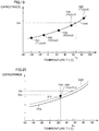
- Fig. 19 is a diagram for explaining a first example of how the temperature detecting unit 112 estimates a temperature Tc.
- capacitance values (Cini1, Cini2, Cini3, Cini4, and Cini5) are measured at given temperatures (T1, T2, T3, T4, and T5) when the ultrasonic transducer 100 in the factory default state is known to have no anomaly. There may be either one or a plurality of temperature points.
- the measured values at measurement points P21 to P25 are stored in the capacitance storage unit 514. From the capacitance values stored, the temperature estimating unit 516 determines a temperature-capacitance value relation for each individual ultrasonic transducer.
- the temperature-capacitance value relation can be calculated, for example, by storing table data of temperatures and capacitance values, and linearly interpolating the stored data.
- the relation may be mathematically expressed, for example, by a linear, quadratic, or polynomial expression, and coefficients in the mathematical expression may be determined from the measurement points P21 to P25.
- the temperature estimating unit 516 determines a temperature corresponding to a capacitance value Cm obtained from the capacitance detecting unit 512 during use. The temperature estimating unit 516 thus estimates the estimated temperature Tc.
- the temperature-capacitance characteristic data may be measured, as illustrated in Fig. 19 , for each individual ultrasonic transducer so that the data can be used to determine the estimated temperature Tc. It takes time, however, to measure and record the temperature-capacitance characteristic data for each individual ultrasonic transducer. Therefore, it is more realistic to perform a second example (described below) in which the initial value Cini at the standard temperature Tstd is measured and recorded for each individual transducer, and common data is used to compensate for a capacitance shift ⁇ C associated with a change in temperature characteristic.
- Fig. 20 is a diagram for explaining the second example of how the temperature detecting unit 112 estimates the temperature Tc.
- An ultrasonic transducer's temperature-capacitance characteristic (Corg) used in common by a plurality of ultrasonic apparatuses, is stored in the temperature estimating unit 516.
- the temperature-capacitance characteristic (Corg) may be stored as a function (mathematical expression) of temperature, or may be stored as a data table like a map.
- the capacitance value shift ⁇ C between the capacitance value Cini at the temperature Tstd, corresponding to each individual ultrasonic transducer 100, and the temperature-capacitance characteristic (Corg), is calculated.
- the capacitance value shift ⁇ C is a shift resulting from an individual difference.
- the temperature-capacitance characteristic (Corg) is shifted by ⁇ C to determine the temperature-capacitance characteristic (Cstd).
- the temperature estimating unit 516 determines a temperature corresponding to the capacitance value Cm obtained from the capacitance detecting unit 512 during use. The temperature estimating unit 516 thus estimates the estimated temperature Tc.
- the temperature estimating unit 516 may calculate a difference ⁇ C1 between the measured capacitance value Cm and the capacitance value Cini read from the capacitance storage unit 514 and output, as the estimated temperature Tc, a temperature at which Corg is changed by ⁇ C1 from that at Tstd.
- the Q-factor estimating unit 216 Upon receiving the estimated temperature Tc from the temperature detecting unit 112, the Q-factor estimating unit 216 outputs the estimated Q factor Qc.
- the anomaly determining unit 219 performs an operation similar to that described in the second embodiment and outputs a signal SR5 representing the determination result.
- the ultrasonic apparatus detects a temperature on the basis of a detected change in the capacitance of the piezoelectric element originally included in the ultrasonic transducer 100, and thus does not require, for example, an additional temperature sensor.
- the fifth embodiment which requires no additional sensor, can achieve the functions of the first to fourth embodiments at low cost.
- the Q factor estimate Qc is determined through the use of the temperature Tm or Tc.
- the resonant frequency fc or the Q factor estimate Qc is estimated directly from the measured capacitance value Cm of the ultrasonic transducer 100.
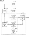
- Fig. 21 is a block diagram illustrating a configuration of an ultrasonic apparatus according to the sixth embodiment.
- the ultrasonic apparatus of the sixth embodiment includes the ultrasonic transducer 100, the driving circuit 104, the receiving circuit 106, and an anomaly detector 610.
- the anomaly detector 610 includes the Q-factor detecting unit 214, the Q-factor storage unit 218, the capacitance detecting unit 512, a Q-factor estimating unit 616, and the anomaly determining unit 219.
- Fig. 22 is a diagram for explaining a first example of estimation performed by the Q-factor estimating unit 616.
- Q factors Qini1, Qini2, Qini3, Qini4, and Qini5 are measured at capacitance values (Cini1, Cini2, Cini3, Cini4, and Cini5) corresponding to given temperatures (T1, T2, T3, T4, and T5) when the ultrasonic transducer 100 in the factory default state is known to have no anomaly.
- the measured values at measurement points P31 to P35 are stored in the Q-factor storage unit 218. From the Q factors stored, the Q-factor estimating unit 616 determines a capacitance value-Q factor relation for each individual ultrasonic transducer.
- the capacitance value-Q factor relation can be calculated, for example, by storing table data of capacitance values and Q factors, and linearly interpolating the stored data.
- the relation may be mathematically expressed, for example, by a linear, quadratic, or polynomial expression, and coefficients in the mathematical expression may be determined from the measurement points P31 to P35.
- the Q-factor estimating unit 616 determines a value corresponding to the capacitance value Cm obtained from the capacitance detecting unit 512 during use. The Q-factor estimating unit 616 thus estimates the estimated Q factor Qc.
- the capacitance value-Q factor characteristic data may be measured, as illustrated in Fig. 22 , for each individual ultrasonic transducer so that the data can be used to determine the estimated Q factor Qc. It takes time, however, to measure and record the capacitance value-Q factor characteristic data for each individual ultrasonic transducer. Therefore, it is more realistic to perform a second example (described below) in which the initial value Qini at the capacitance value Cstd corresponding to the standard temperature Tstd is measured and recorded for each individual transducer, and common data is used to compensate for a Q factor shift ⁇ Q associated with a change in capacitance characteristic.
- Fig. 23 is a diagram for explaining a second example of estimation performed by the Q-factor estimating unit 616.
- the capacitance value Cstd and the Q factor Qini of the ultrasonic transducer 100 measured at a predetermined temperature are stored in the Q-factor storage unit 218.
- An ultrasonic transducer's capacitance value-Q factor characteristic (Qorg) used in common by a plurality of ultrasonic apparatuses, is stored in the Q-factor estimating unit 616.
- the temperature-Q factor characteristic (Qorg) may be stored as a function (mathematical expression) of temperature, or may be stored as a data table like a map.
- the Q factor shift ⁇ Q between the Q factor Qini at the capacitance Cstd, corresponding to each individual ultrasonic transducer 100, and the capacitance value-Q factor characteristic (Qorg), is calculated.
- the Q factor shift ⁇ Q is a shift resulting from an individual difference.
- the capacitance value-Q factor characteristic (Qorg) is shifted by ⁇ Q to determine the capacitance value-Q factor characteristic (Qstd).
- the Q-factor estimating unit 616 determines a value corresponding to the capacitance value Cm obtained from the capacitance detecting unit 512 during use. The Q-factor estimating unit 616 thus estimates the estimated Q factor Qc.
- a difference ⁇ Q1 between a Q factor corresponding to the predetermined capacitance value Cstd and a Q factor at the capacitance value Cm in the capacitance value-Q factor characteristic (Qorg) may be calculated and added to Qini to determine Qc.
- the anomaly determining unit 219 determines an anomaly of the ultrasonic transducer 100 and outputs a signal SR6 representing the determination result.
- the temperature detecting unit 112 of the first to fifth embodiments is replaced by the capacitance detecting unit 512.
- the frequency estimating unit and the Q-factor estimating unit 616 estimate the Q factor directly from the measured capacitance Cm, not from the temperature.
- Fig. 24 is a block diagram illustrating a configuration of an ultrasonic apparatus according to a modification of the sixth embodiment.
- the ultrasonic apparatus according to this modification of the sixth embodiment includes the ultrasonic transducer 100, the driving circuit 104, the receiving circuit 106, and an anomaly detector 710.
- the anomaly detector 710 includes the frequency detecting unit 114, the frequency storage unit 118, a frequency estimating unit 716, the capacitance detecting unit 512, and the anomaly determining unit 119.
- the frequency estimating unit 716 shifts the capacitance-resonant frequency characteristic by taking fini into account to determine the frequency estimate fc.
- the Q factor estimate Qc varying with changes in ambient environment, such as temperature is determined directly through the use of map data or relational expression representing a relation between capacitance and Q factor.
- map data or relational expression representing a relation between capacitance and Q factor.
- a seventh embodiment is characterized in that a capacitance change rate is determined so as to reduce errors caused by applying such common map data or relational expression. Determining a capacitance change rate is applicable to any of the first to fourth embodiments.
- the change rate (%) of capacitance value associated with changes in temperature does not significantly vary from one element to another. Therefore, if the relation between capacitance change rates and Q factors is expressed in the form of a map or a relational expression, the resulting data can be used as common data during manufacture.
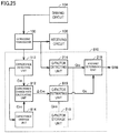
- Fig. 25 is a block diagram illustrating a configuration of an ultrasonic apparatus according to the seventh embodiment.
- the ultrasonic apparatus of the seventh embodiment includes the ultrasonic transducer 100, the driving circuit 104, the receiving circuit 106, and an anomaly detector 810.
- the anomaly detector 810 includes the Q-factor detecting unit 214, the Q-factor storage unit 218, the capacitance detecting unit 512, a capacitance storage unit 814, a capacitance change rate calculating unit 812, a Q-factor estimating unit 816, and the anomaly determining unit 219.
- the capacitance change rate calculating unit 812 outputs, as a capacitance change rate ⁇ Cm (%), the rate of change of the capacitance value Cm detected by the capacitance detecting unit 512 with respect to the capacitance value Cini.
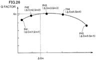
- the Q-factor estimating unit 816 stores a relation between capacitance change rates, ⁇ Cini1, ⁇ Cini2, ⁇ Cini3, ⁇ Cini4, and ⁇ Cini5, of the ultrasonic transducer 100 and Q factors at given temperatures (T1, T2, T3, T4, and T5) (capacitance change rate-Q factor characteristic). This relation is a value that is applicable in common to individual elements.
- Fig. 26 is a diagram for explaining estimation performed by the Q-factor estimating unit 816.
- the Q-factor estimating unit 816 calculates the capacitance change rate-Q factor characteristic by linear interpolation between measurement points P41 to P45.
- the relation may be mathematically expressed, for example, by a polynomial expression, and coefficients in the mathematical expression may be determined from the measurement points P41 to P45.
- the Q-factor estimating unit 816 determines a Q factor corresponding to the capacitance change rate ⁇ Cm from the capacitance change rate-Q factor characteristic, and outputs the estimate Qc.
- Fig. 27 is a block diagram illustrating a configuration of an ultrasonic apparatus according to a modification of the seventh embodiment.
- the ultrasonic apparatus according to this modification of the seventh embodiment includes the ultrasonic transducer 100, the driving circuit 104, the receiving circuit 106, and an anomaly detector 910.
- the anomaly detector 910 includes the frequency detecting unit 114, the frequency storage unit 118, a frequency estimating unit 916, the capacitance detecting unit 512, the capacitance storage unit 814, the capacitance change rate calculating unit 812, and the anomaly determining unit 119.
- the frequency estimating unit 916 determines a resonant frequency corresponding to the capacitance change rate ⁇ Cm from the capacitance change rate-resonant frequency characteristic, and outputs the estimated resonant frequency fc.
- ultrasonic apparatus 50: piezoelectric element, 51, 52: electrode, 60: case, 61: tubular portion, 62: bottom portion, 63: sound absorber, 71: resin, 80, 81: terminal, 100: ultrasonic transducer, 101: microprocessor, 102: memory, 103: detecting circuit, 104: driving circuit, 105: power supply, 106: receiving circuit, 110, 210, 310, 410, 510, 610, 710, 810, 910: anomaly detector, 112: temperature detecting unit, 114: frequency detecting unit, 116: frequency estimating unit, 118: frequency storage unit, 119, 219, 319, 419: anomaly determining unit, 214: Q-factor detecting unit, 216, 616, 816: Q-factor estimating unit, 218: Q-factor storage unit, 320: determining section, 512: capacitance detecting unit, 514, 814: capacitance storage unit, 516: temperature estimating unit, 812
Landscapes
- Engineering & Computer Science (AREA)
- Physics & Mathematics (AREA)
- Computer Networks & Wireless Communication (AREA)
- General Physics & Mathematics (AREA)
- Signal Processing (AREA)
- Radar, Positioning & Navigation (AREA)
- Remote Sensing (AREA)
- Acoustics & Sound (AREA)
- Transducers For Ultrasonic Waves (AREA)
- Measurement Of Velocity Or Position Using Acoustic Or Ultrasonic Waves (AREA)
- Investigating Or Analyzing Materials By The Use Of Ultrasonic Waves (AREA)
Abstract
Description
- The present invention relates to an ultrasonic apparatus, and particularly relates to an ultrasonic apparatus capable of detecting anomalies of an ultrasonic transducer included therein.
- Ultrasonic apparatuses are used in practice, in which an ultrasonic transducer transmits ultrasonic waves, receives reflected waves from an object to be detected, and thereby measures, for example, a distance to the object to be detected.
- If a foreign substance, such as mud, adheres to the vibrating surface of the ultrasonic transducer, or if water droplets adhering to the vibrating surface freeze, an ultrasonic vibrator is unable to transmit and receive waves. This leads to failure in the detection of an obstacle existing in front of the ultrasonic vibrator.
- Japanese Patent No.
2998232 - Patent Document 1: Japanese Patent No.
2998232 - The resonant frequency changes as the temperature changes. Therefore, with an anomaly detecting method which involves using a measured resonant frequency alone, it may be difficult to distinguish between an anomaly and a temperature change.
- The present invention has been made to solve the problem described above. An object of the present invention is to provide an ultrasonic apparatus that is capable of accurately detecting anomalies of an ultrasonic transducer. Solution to Problem
- An ultrasonic apparatus according to an aspect of the present disclosure includes an ultrasonic transducer, a driving circuit, a receiving circuit, a frequency detecting unit, a storage unit, a temperature detecting unit, and a determining unit. The driving circuit causes the ultrasonic transducer to transmit sonic waves. The receiving circuit receives sonic waves received by the ultrasonic transducer. The frequency detecting unit detects a resonant frequency of the ultrasonic transducer. The storage unit stores a resonant frequency of the ultrasonic transducer at a predetermined temperature. The determining unit determines an anomaly of the ultrasonic transducer on the basis of a temperature detected by the temperature detecting unit, the resonant frequency stored in the storage unit, and the resonant frequency detected by the frequency detecting unit.
- An ultrasonic apparatus according to a second aspect of the present disclosure includes an ultrasonic transducer; a driving circuit configured to cause the ultrasonic transducer to transmit sonic waves; a receiving circuit configured to receive sonic waves received by the ultrasonic transducer; a Q-factor detecting unit configured to detect a Q factor of the ultrasonic transducer; a storage unit configured to store a Q factor of the ultrasonic transducer at a predetermined temperature; a temperature detecting unit; and a determining unit configured to determine an anomaly of the ultrasonic transducer on the basis of a temperature detected by the temperature detecting unit, the Q factor stored in the storage unit, and the Q factor detected by the Q-factor detecting unit.
- An ultrasonic apparatus according to a third aspect of the present disclosure includes an ultrasonic transducer; a driving circuit configured to cause the ultrasonic transducer to transmit sonic waves; a receiving circuit configured to receive sonic waves received by the ultrasonic transducer; a frequency detecting unit configured to detect a resonant frequency of the ultrasonic transducer; a first storage unit configured to store a resonant frequency of the ultrasonic transducer at a predetermined temperature; a Q-factor detecting unit configured to detect a Q factor of the ultrasonic transducer; a second storage unit configured to store a Q factor of the ultrasonic transducer at the predetermined temperature; a temperature detecting unit; and a determining unit configured to determine an anomaly of the ultrasonic transducer on the basis of a temperature detected by the temperature detecting unit, the resonant frequency stored in the first storage unit, the resonant frequency detected by the frequency detecting unit, the Q factor stored in the second storage unit, and the Q factor detected by the Q-factor detecting unit.
- The determining unit preferably includes a resonant frequency estimating unit configured to estimate a resonant frequency at the temperature detected by the temperature detecting unit, on the basis of the resonant frequency stored in the first storage unit; a first determination processing unit configured to determine whether the resonant frequency detected by the frequency detecting unit is normal, on the basis of the resonant frequency estimated by the resonant frequency estimating unit; a Q-factor estimating unit configured to estimate a Q factor at the temperature detected by the temperature detecting unit, on the basis of the Q factor stored in the second storage unit; and a second determination processing unit configured to determine whether the Q factor detected by the Q-factor detecting unit is normal, on the basis of the Q factor estimated by the Q-factor estimating unit.
- The determining unit preferably includes a resonant frequency estimating unit configured to estimate a resonant frequency at the temperature detected by the temperature detecting unit, on the basis of the resonant frequency stored in the first storage unit; a Q-factor estimating unit configured to estimate a Q factor at the temperature detected by the temperature detecting unit, on the basis of the Q factor stored in the second storage unit; and an anomaly determining unit configured to determine whether the ultrasonic transducer is normal, on the basis of a combination of the resonant frequency estimated by the resonant frequency estimating unit and the Q factor estimated by the Q-factor estimating unit.
- The temperature detecting unit preferably includes a capacitance detecting unit configured to detect a capacitance of the ultrasonic transducer; a capacitance storage unit configured to store a capacitance of the ultrasonic transducer at the predetermined temperature; and a temperature estimating unit configured to estimate a temperature on the basis of the capacitance detected by the capacitance detecting unit and the capacitance stored by the capacitance storage unit.
- An ultrasonic apparatus according to a fourth aspect of the present disclosure includes an ultrasonic transducer; a driving circuit configured to cause the ultrasonic transducer to transmit sonic waves; a receiving circuit configured to receive sonic waves received by the ultrasonic transducer; a Q-factor detecting unit configured to detect a Q factor of the ultrasonic transducer; a storage unit configured to store a Q factor of the ultrasonic transducer at a predetermined temperature; a capacitance detecting unit configured to detect a capacitance of the ultrasonic transducer; a capacitance storage unit configured to store a capacitance of the ultrasonic transducer at the predetermined temperature; and a determining unit configured to determine an anomaly of the ultrasonic transducer on the basis of the capacitance detected by the capacitance detecting unit, the Q factor stored in the storage unit, and the Q factor detected by the Q-factor detecting unit.
- An ultrasonic apparatus according to a fifth aspect of the present disclosure includes an ultrasonic transducer; a driving circuit configured to cause the ultrasonic transducer to transmit sonic waves; a receiving circuit configured to receive sonic waves received by the ultrasonic transducer; a frequency detecting unit configured to detect a resonant frequency of the ultrasonic transducer; a storage unit configured to store a resonant frequency of the ultrasonic transducer at a predetermined temperature; a capacitance detecting unit configured to detect a capacitance of the ultrasonic transducer; a capacitance storage unit configured to store a capacitance of the ultrasonic transducer at the predetermined temperature; and a determining unit configured to determine an anomaly of the ultrasonic transducer on the basis of the capacitance detected by the capacitance detecting unit, the resonant frequency stored in the storage unit, and the resonant frequency detected by the frequency detecting unit. Advantageous Effects of Invention
- The present invention enables accurate detection of anomalies of the ultrasonic transducer.
-
- [
Fig. 1] Fig. 1 is a schematic block diagram illustrating a configuration of an ultrasonic apparatus including an ultrasonic transducer. - [
Fig. 2] Fig. 2 is a cross-sectional view of anultrasonic transducer 100. - [
Fig. 3] Fig. 3 is a block diagram illustrating a configuration of an ultrasonic apparatus according to a first embodiment. - [
Fig. 4] Fig. 4 is a diagram for explaining a first example of how a frequency estimatingunit 116 estimates frequency fc. - [
Fig. 5] Fig. 5 is a diagram for explaining a second example of how thefrequency estimating unit 116 estimates frequency fc. - [
Fig. 6] Fig. 6 is a block diagram illustrating a configuration of an ultrasonic apparatus according to a second embodiment. - [
Fig. 7] Fig. 7 is a diagram for explaining a first example of how a Q-factor estimatingunit 216 estimates Q factor Qc. - [
Fig. 8] Fig. 8 is a diagram for explaining a second example of how the Q-factor estimatingunit 216 estimates Q factor Qc. - [
Fig. 9] Fig. 9 is a graph showing a relation between adhesion of water droplets and change in resonant frequency. - [
Fig. 10] Fig. 10 is a graph showing a relation between adhesion of water droplets and change in Q factor. - [
Fig. 11] Fig. 11 is a graph showing a relation between adhesion of mud and change in resonant frequency. - [
Fig. 12] Fig. 12 is a graph showing a relation between adhesion of mud and change in Q factor. - [
Fig. 13] Fig. 13 is a flowchart for explaining a determination process performed in a third embodiment. - [
Fig. 14] Fig. 14 is a block diagram illustrating a configuration of an ultrasonic apparatus according to the third embodiment. - [
Fig. 15] Fig. 15 is a diagram for explaining an operation of an anomaly determiningunit 319. - [
Fig. 16] Fig. 16 is a block diagram illustrating a configuration of an ultrasonic apparatus according to a fourth embodiment. - [
Fig. 17] Fig. 17 is a diagram for explaining a determination process performed by an anomaly determiningunit 419. - [
Fig. 18] Fig. 18 is a block diagram illustrating a configuration of an ultrasonic apparatus according to a fifth embodiment. - [
Fig. 19] Fig. 19 is a diagram for explaining a first example of how atemperature detecting unit 112 estimates temperature Tc. - [
Fig. 20] Fig. 20 is a diagram for explaining a second example of how thetemperature detecting unit 112 estimates temperature Tc. - [
Fig. 21] Fig. 21 is a block diagram illustrating a configuration of an ultrasonic apparatus according to a sixth embodiment. - [
Fig. 22] Fig. 22 is a diagram for explaining a first example of estimation performed by a Q-factor estimatingunit 616. - [
Fig. 23] Fig. 23 is a diagram for explaining a second example of estimation performed by the Q-factor estimatingunit 616. - [
Fig. 24] Fig. 24 is a block diagram illustrating a configuration of an ultrasonic apparatus according to a modification of the sixth embodiment. - [
Fig. 25] Fig. 25 is a block diagram illustrating a configuration of an ultrasonic apparatus according to a seventh embodiment. - [
Fig. 26] Fig. 26 is a diagram for explaining estimation performed by a Q-factor estimatingunit 816. - [
Fig. 27] Fig. 27 is a block diagram illustrating a configuration of an ultrasonic apparatus according to a modification of the seventh embodiment. - Embodiments of the present invention will now be described in detail with reference to the drawings. The same or equivalent parts throughout the drawings are denoted by the same reference numerals and their description will not be repeated.
-
Fig. 1 is a schematic block diagram illustrating a configuration of an ultrasonic apparatus including an ultrasonic transducer. Anultrasonic apparatus 1 includes anultrasonic transducer 100, amicroprocessor 101, amemory 102, a detectingcircuit 103, adriving circuit 104, apower supply 105, areceiving circuit 106, and ananomaly detector 110. - The
microprocessor 101 reads data stored in thememory 102 and outputs, to thedriving circuit 104, a control signal suitable for driving theultrasonic transducer 100. Thepower supply 105 outputs, for example, a direct-current voltage of 12 V to thedriving circuit 104. The drivingcircuit 104 generates an alternating-current voltage from the direct-current voltage on the basis of the control signal output from themicroprocessor 101. The alternating-current voltage is boosted, as appropriate, by an amplifying circuit (not shown) and supplied to theultrasonic transducer 100. Theultrasonic transducer 100 is driven, and ultrasonic waves are transmitted from theultrasonic transducer 100, for example, into the air. - When the
ultrasonic transducer 100 receives reflected waves from a target, a receive signal generated in theultrasonic transducer 100 is transmitted as a voltage value to the receivingcircuit 106, further transmitted through the detectingcircuit 103, and input to themicroprocessor 101. Themicroprocessor 101 thus acquires information about the presence and movement of the target. Theultrasonic apparatus 1 can be used, for example, as an ultrasonic sensor mounted on a vehicle. -
Fig. 2 is a cross-sectional view of theultrasonic transducer 100. The configuration of the ultrasonic transducer disclosed inFig. 2 is merely an example. Even when an ultrasonic transducer having a different configuration is used, the ultrasonic apparatus of the present embodiment can detect anomalies of the ultrasonic transducer. Theultrasonic transducer 100 illustrated inFig. 2 includes apiezoelectric element 50, acase 60, asound absorber 63, andterminals case 60 has a cylindrical shape with a bottom. Thecase 60 is made of, for example, light-weight aluminum with high elasticity. Thecase 60 is made, for example, by an aluminum forging or cutting process. - The
case 60 includes a disk-shapedbottom portion 62 and a cylindricaltubular portion 61 disposed along the periphery of thebottom portion 62. Thepiezoelectric element 50 is made of, for example, PZT ceramic. Thepiezoelectric element 50 is disposed on the inner surface of thebottom portion 62 and bonded thereto with an adhesive. While theultrasonic transducer 100 is being driven, thepiezoelectric element 50 vibrates in bending directions together with thebottom portion 62. The inner space of thecase 60 is filled withresin 71. Thesound absorber 63 is formed by a molded body of sponge material or the like, and is interposed between theresin 71 and aportion 72 for accommodating thepiezoelectric element 50. Thesound absorber 63 is opposite, and at a distance from, thepiezoelectric element 50. - The
piezoelectric element 50 has twoelectrodes electrode 52, with a wire and thecase 60 interposed therebetween. The terminal 81 is electrically connected to theelectrode 51, with a wire interposed therebetween. - The
ultrasonic transducer 100 illustrated inFig. 1 may be a two-terminal transducer, such as that illustrated inFig. 2 , or may be a three-terminal transducer with GND and transmitting and receiving terminals. -
Fig. 3 is a block diagram illustrating a configuration of an ultrasonic apparatus according to a first embodiment. The ultrasonic apparatus of the first embodiment includes theultrasonic transducer 100, the drivingcircuit 104, the receivingcircuit 106, and theanomaly detector 110. - The
anomaly detector 110 includes afrequency detecting unit 114, afrequency storage unit 118, afrequency estimating unit 116, atemperature detecting unit 112, and ananomaly determining unit 119. - The driving
circuit 104 outputs a driving signal in such a manner as to cause theultrasonic transducer 100 to transmit sonic waves. The receivingcircuit 106 receives sonic waves received by theultrasonic transducer 100. - The
frequency detecting unit 114 detects a resonant frequency fm of theultrasonic transducer 100. Thefrequency storage unit 118 stores the resonant frequency fm of theultrasonic transducer 100 at a predetermined temperature. For example, the resonant frequency fm detected by thefrequency detecting unit 114 when, in the process of producing ultrasonic apparatuses at the factory, theultrasonic transducer 100 is resonated in an atmosphere of predetermined temperature, is stored as an initial value fini in thefrequency storage unit 118. - The
frequency detecting unit 114 and thetemperature detecting unit 112 of any known types may be used. For example, thefrequency detecting unit 114 may be a circuit that measures a resonant frequency from a reverberation frequency, as described for example in Japanese Unexamined Patent Application Publication No.2015-10888 temperature detecting unit 112 may be a thermo-sensitive element, such as a thermistor, or may be configured to receive temperature information from an external temperature sensor mounted, for example, on a vehicle. -
Fig. 4 is a diagram for explaining a first example of how thefrequency estimating unit 116 estimates a frequency fc. Referring toFig. 3 andFig. 4 , resonant frequencies (fini1, fini2, fini3, fini4, and fini5) are measured at given temperatures (T1, T2, T3, T4, and T5) when theultrasonic transducer 100 in the factory default state is known to have no anomaly. There may be either one or a plurality of temperature points. The measured values at measurement points P1 to P5 are stored in thefrequency storage unit 118. From the frequencies stored, thefrequency estimating unit 116 determines a temperature-resonant frequency relation fstd for each individual ultrasonic transducer. - The temperature-resonant frequency relation can be calculated, for example, by storing table data of temperatures and resonant frequencies, and linearly interpolating the stored data. The relation may be mathematically expressed, for example, by a linear, quadratic, or polynomial expression, and coefficients in the mathematical expression may be determined from the measurement points P1 to P5.
- From fstd given by such a mathematical expression or table, the
frequency estimating unit 116 determines a value corresponding to a temperature Tm obtained from thetemperature detecting unit 112 during use. Thefrequency estimating unit 116 thus estimates the estimated resonant frequency fc. - The temperature characteristic data may be measured, as illustrated in
Fig. 4 , for each individual ultrasonic transducer so that the data can be used to determine the estimated resonant frequency fc. It takes time, however, to measure and record the temperature characteristic data for each individual ultrasonic transducer. Therefore, it is more realistic to perform a second example (described below) in which the initial value fini at a standard temperature Tstd is measured and recorded for each individual transducer, and common standard data is used to compensate for a frequency shift Δf associated with a change in temperature characteristic. -
Fig. 5 is a diagram for explaining the second example of how thefrequency estimating unit 116 estimates the frequency fc. Referring toFig. 3 andFig. 5 , the resonant frequency fini of theultrasonic transducer 100 measured at a predetermined temperature (e.g., Tstd = 25°C) (corresponding to P6 inFig. 5 ) is stored in thefrequency storage unit 118. An ultrasonic transducer's temperature-resonant frequency characteristic (forg inFig. 5 ), used in common by a plurality of ultrasonic apparatuses, is stored in thefrequency estimating unit 116. The temperature-resonant frequency characteristic (forg) may be stored as a function (mathematical expression) of temperature, or may be stored as a data table like a map. - The shift Δf between the resonant frequency fini at the temperature Tstd, corresponding to each individual
ultrasonic transducer 100, and the temperature-resonant frequency characteristic (forg), is calculated. The frequency shift Δf is a shift resulting from an individual difference. Then, the temperature-resonant frequency characteristic (forg) is shifted by Δf to determine the temperature-resonant frequency characteristic (fstd). From fstd given by a mathematical expression or table, thefrequency estimating unit 116 determines a value corresponding to the temperature Tm obtained from thetemperature detecting unit 112 during use. Thefrequency estimating unit 116 thus estimates the estimated resonant frequency fc. - Although not shown, a difference Δf1 between a resonant frequency corresponding to the predetermined temperature Tstd and a resonant frequency at the temperature Tm in the temperature-resonant frequency characteristic (forg) may be calculated and added to fini to determine fc.
- Referring back to
Fig. 3 , upon receiving the current measured temperature Tm from thetemperature detecting unit 112, thefrequency estimating unit 116 outputs the estimated resonant frequency fc. Note that although fini stored in thefrequency storage unit 118 is transmitted to thefrequency estimating unit 116 inFig. 3 , fstd shown inFig. 4 and Fig. 5 may be computed and stored in thefrequency storage unit 118 in advance and referenced by thefrequency estimating unit 116. - The
anomaly determining unit 119 determines an anomaly of theultrasonic transducer 100 on the basis of the temperature Tm detected by thetemperature detecting unit 112, the resonant frequency fini stored in thefrequency storage unit 118, and the resonant frequency fm detected by thefrequency detecting unit 114. Theanomaly determining unit 119 then outputs a signal SR1 representing the determination result. - More specifically, the
frequency estimating unit 116 estimates the frequency estimate fc at the temperature Tm on the basis of the temperature Tm and the initial value fini, and theanomaly determining unit 119 compares the frequency estimate fc with the resonant frequency fm, which is a measured value, to determine whether the measured value is anomalous. For example, theanomaly determining unit 119 determines a positive-side threshold f(+) and a negative-side threshold f(-), with the frequency estimate fc at the center. Then, if f(-) < fm < f(+) is satisfied, theanomaly determining unit 119 determines that the measured value is normal, and if not satisfied, theanomaly determining unit 119 determines that the measured value is anomalous. - With the configuration described above, the ultrasonic apparatus according to the first embodiment can detect anomalies of the ultrasonic transducer more accurately than before.
- That is, the method described in Japanese Patent No.
2998232 temperature detecting unit 112, in addition to thefrequency detecting unit 114, so that a change in frequency at a detected temperature is reflected in a determination threshold. This enables determination as to whether the change in frequency is caused by a temperature change or by an anomaly. - A resonant frequency is used as a parameter to determine an anomaly in the first embodiment, but a Q factor is used in a second embodiment. The Q factor is an index generally used as a value "quality factor (Q)" representing the degree of sharpness, that is, how sharp the resonance peak of the resonant circuit is. The inventors of the present application have discovered that an anomaly, such as adhesion of mud, can also be detected as a change in Q factor.
-
Fig. 6 is a block diagram illustrating a configuration of an ultrasonic apparatus according to the second embodiment. The ultrasonic apparatus according to the second embodiment includes theultrasonic transducer 100, the drivingcircuit 104, the receivingcircuit 106, and ananomaly detector 210. - The
anomaly detector 210 includes a Q-factor detecting unit 214, a Q-factor storage unit 218, a Q-factor estimating unit 216, thetemperature detecting unit 112, and ananomaly determining unit 219. - The description of the driving
circuit 104, the receivingcircuit 106, and thetemperature detecting unit 112, which are the same as those of the first embodiment, will not be repeated here. - The Q-
factor detecting unit 214 detects a Q factor Qm of theultrasonic transducer 100. The Q-factor storage unit 218 stores the Q factor Qm of theultrasonic transducer 100 at a predetermined temperature. For example, the Q factor Qm detected by the Q-factor detecting unit 214 when, in the process of producing ultrasonic apparatuses at the factory, theultrasonic transducer 100 is vibrated in an atmosphere of predetermined temperature, is stored as an initial value Qini in the Q-factor storage unit 218. - The Q-
factor detecting unit 214 of any known type may be used. For example, the Q-factor detecting unit 214 measures the Q factor from the attenuation curve of reverberation frequency as described, for example, in Japanese Unexamined Patent Application Publication No.2015-10888 -
Fig. 7 is a diagram for explaining a first example of how the Q-factor estimating unit 216 estimates a Q factor Qc. Referring toFig. 6 andFig. 7 , Q factors (Qini1, Qini2, Qini3, Qini4, and Qini5) are measured at given temperatures (T1, T2, T3, T4, and T5) when theultrasonic transducer 100 in the factory default state is known to have no anomaly. There may be either one or a plurality of temperature points. The measured values at measurement points P11 to P15 are stored in the Q-factor storage unit 218. From the Q factors stored, the Q-factor estimating unit 216 determines a temperature-Q factor relation for each individual ultrasonic transducer. - The temperature-Q factor relation can be calculated, for example, by storing table data of temperatures and Q factors, and linearly interpolating the stored data. The relation may be mathematically expressed, for example, by a linear, quadratic, or polynomial expression, and coefficients in the mathematical expression may be determined from the measurement points P11 to P15.
- From Qstd given by such a mathematical expression or table, the Q-
factor estimating unit 216 determines a value corresponding to the temperature Tm obtained from thetemperature detecting unit 112 during use. The Q-factor estimating unit 216 thus estimates the estimated Q factor Qc. - The temperature characteristic data may be measured, as illustrated in
Fig. 7 , for each individual ultrasonic transducer so that the data can be used to determine the estimated Q factor Qc. It takes time, however, to measure and record the temperature characteristic data for each individual ultrasonic transducer. Therefore, it is more realistic to perform a second example (described below) in which the initial value Qini at the standard temperature Tstd is measured and recorded for each individual transducer, and common data is used to compensate for a Q factor shift ΔQ associated with a change in temperature characteristic. -
Fig. 8 is a diagram for explaining the second example of how the Q-factor estimating unit 216 estimates the Q factor Qc. Referring toFig. 6 andFig. 8 , the Q factor Qini of theultrasonic transducer 100 measured at a predetermined temperature (e.g., Tstd = 25°C) is stored in the Q-factor storage unit 218. An ultrasonic transducer's temperature-Q factor characteristic (Qorg), used in common by a plurality of ultrasonic apparatuses, is stored in the Q-factor estimating unit 216. The temperature-Q factor characteristic (Qorg) may be stored as a function (mathematical expression) of temperature, or may be stored as a data table like a map. - The Q factor shift ΔQ between the Q factor Qini at the temperature Tstd, corresponding to each individual
ultrasonic transducer 100, and the temperature-Q factor characteristic (Qorg), is calculated. The Q factor shift ΔQ is a shift resulting from an individual difference. Then, the temperature-Q factor characteristic (Qorg) is shifted by ΔQ to determine the temperature-Q factor characteristic (Qstd). From Qstd given by a mathematical expression or table, the Q-factor estimating unit 216 determines a value corresponding to the temperature Tm obtained from thetemperature detecting unit 112 during use. The Q-factor estimating unit 216 thus estimates the estimated Q factor Qc. - Although not shown, a difference ΔQ1 between a Q factor corresponding to the predetermined temperature Tstd and a Q factor at the temperature Tm in the temperature-Q factor characteristic (Qorg) may be calculated and added to Qini to determine Qc.
- Upon receiving the current measured temperature Tm from the
temperature detecting unit 112, the Q-factor estimating unit 216 outputs the estimated Q factor Qc. Note that although Qini stored in the Q-factor storage unit 218 is transmitted to the Q-factor estimating unit 216 inFig. 3 , Qstd shown inFig. 7 and Fig. 8 may be computed and stored in the Q-factor storage unit 218 in advance and referenced by the Q-factor estimating unit 216. - The
anomaly determining unit 219 determines an anomaly of theultrasonic transducer 100 on the basis of the temperature Tm detected by thetemperature detecting unit 112, the Q factor Qini stored in the Q-factor storage unit 218, and the Q factor Qm detected by the Q-factor detecting unit 214. Theanomaly determining unit 219 then outputs a signal SR2 representing the determination result. - More specifically, the Q-
factor estimating unit 216 estimates the Q factor estimate Qc at the temperature Tm on the basis of the temperature Tm and the initial value Qini, and theanomaly determining unit 219 compares the frequency estimate Qc with Qm, which is a measured value, to determine whether the measured value is anomalous. For example, theanomaly determining unit 219 determines a positive-side threshold Q(+) and a negative-side threshold Q(-), with the Q factor estimate Qc at the center. Then, if Q(-) < Qm < Q(+) is satisfied, theanomaly determining unit 219 determines that the measured value is normal, and if not satisfied, theanomaly determining unit 219 determines that the measured value is anomalous. - With the configuration described above, the ultrasonic apparatus according to the second embodiment performs temperature compensation of the Q factor, and thus can accurately detect anomalies of the ultrasonic transducer. Anomaly detection which involves using Q factors alone has not been conventionally performed. It can therefore be expected that previously undetectable anomalies will be detected.
- In the second embodiment, a Q factor (sharpness of resonance) is used to determine an anomaly. In a third embodiment, anomalies can be classified by observing changes in both resonant frequency and Q factor at the same time.
-
Fig. 9 is a graph showing a relation between adhesion of water droplets and change in resonant frequency.Fig. 10 is a graph showing a relation between adhesion of water droplets and change in Q factor.Fig. 11 is a graph showing a relation between adhesion of mud and change in resonant frequency.Fig. 12 is a graph showing a relation between adhesion of mud and change in Q factor. - As can be seen in
Fig. 9 and Fig. 10 , adhesion of water droplets to the vibrating surface of theultrasonic transducer 100 changes the resonant frequency, but causes little change in Q factor. On the other hand, as can be seen inFig. 11 and Fig. 12 , adhesion of mud changes (or lowers) both the resonant frequency and the Q factor. -
Fig. 13 is a flowchart for explaining a determination process performed in the third embodiment. Referring toFig. 13 , in step S1, an anomaly detector according to the third embodiment stores an initial resonant frequency and an initial Q factor in storage units. Next, the temperature Tm is measured in step S2, and the resonant frequency fc and the Q factor Qc at the current temperature Tm are estimated in step S3. - In parallel with the operations in steps S2 and S3, the current resonant frequency fm and the current Q factor Qm are measured in step S4.
- After completion of the operations in step S3 and step S4, a determination is made as to whether a drop Df in the measured resonant frequency fm relative to the estimated resonant frequency fc is larger than a determination threshold Dfth in step S5. If Df > Dfth holds (YES in S5), the process proceeds from step S5 to step S6, where a determination is made as to whether a drop DQ in Q factor is larger than a determination threshold DQth.
- If DQ > DQth holds in step S6 (YES in S6), the process proceeds to step S7, where it is determined that adhesion of mud to the entire resonating surface (or
bottom portion 62 inFig. 2 ) of theultrasonic transducer 100 is possible. If DC > DQth does not hold (NO in S6), the process proceeds to step S8, where it is determined that adhesion of water to the resonating surface or adhesion of dried mud is possible. - If Df > Dfth does not hold in step S5 (NO in S5), the process proceeds from step S5 to step S9, where a determination is made as to whether the drop DQ in Q factor is larger than the determination threshold DQth.
- If DQ > DQth holds in step S9 (YES in S9), the process proceeds to step S10, where it is determined that adhesion of mud to at least 1/2 of the resonating surface of the
ultrasonic transducer 100 is possible. On the other hand, if DQ > DQth does not hold (NO in S9), the process proceeds to step S11, where it is determined that adhesion of water to the resonating surface is unlikely, and that mud adheres to 1/2 or less of the resonating surface. -
Fig. 14 is a block diagram illustrating a configuration of an ultrasonic apparatus according to the third embodiment. The ultrasonic apparatus according to the first embodiment includes theultrasonic transducer 100, the drivingcircuit 104, the receivingcircuit 106, and ananomaly detector 310. - The
anomaly detector 310 includes thetemperature detecting unit 112, thefrequency detecting unit 114, thefrequency storage unit 118, thefrequency estimating unit 116, and theanomaly determining unit 119. The description of thetemperature detecting unit 112, thefrequency detecting unit 114, thefrequency storage unit 118, thefrequency estimating unit 116, and theanomaly determining unit 119, which are the same as those described in the first embodiment (Fig. 3 ), will not be repeated here. - The
anomaly detector 310 further includes the Q-factor detecting unit 214, the Q-factor storage unit 218, the Q-factor estimating unit 216, and theanomaly determining unit 219. The description of the Q-factor detecting unit 214, the Q-factor storage unit 218, the Q-factor estimating unit 216, and theanomaly determining unit 219, which are the same as those described in the second embodiment (Fig. 6 ), will not be repeated here. - The
anomaly detector 310 further includes ananomaly determining unit 319. Theanomaly determining unit 319 forms a determiningsection 320 together with theanomaly determining units section 320 determines an anomaly of theultrasonic transducer 100 on the basis of the temperature Tm detected by thetemperature detecting unit 112, the resonant frequency fini stored in thefrequency storage unit 118, the resonant frequency fm detected by thefrequency detecting unit 114, the Q factor Qini stored in the Q-factor storage unit 218, and the Q factor Qm detected by the Q-factor detecting unit 214. - From the results of determinations made by the
anomaly determining units anomaly determining unit 319 comprehensively determines the anomaly state. Theanomaly determining unit 319 is capable of determining whether the anomaly state is either adhesion of water, or freezing or adhesion of mud. -
Fig. 15 is a diagram for explaining an operation of theanomaly determining unit 319. Referring toFig. 15 , "f(OK)" means that the signal SR1 indicates that the resonant frequency fm is between the positive-side threshold f(+) and the negative-side threshold f(-) determined by the estimated resonant frequency fc, and "Q(OK)" means that the signal SR2 indicates that the Q factor Qm is between the positive-side threshold Q(+) and the negative-side threshold Q(-) determined by the estimated Q factor Qc. - Also in
Fig. 15 , "f(+)" means that fm is higher than the positive-side threshold f(+), and "f(-)" means that fm is lower than the negative-side threshold f(-). - Also in
Fig. 15 , "Q(+)" means that Qm is larger than the positive-side threshold Q(+), and "Q(-)" means that Qm is smaller than the negative-side threshold Q(-). - If the signal SR1 corresponds to "f(OK)" and the signal SR2 corresponds to "Q(OK)", the
anomaly determining unit 319 outputs "PASS" as a determination result SR3. The output "PASS" indicates that theultrasonic transducer 100 is normal. - If the signal SR1 corresponds to "f(-)" lower than the negative-side threshold and the signal SR2 corresponds to "Q(-)" lower than the negative-side threshold, the
anomaly determining unit 319 outputs "M2" as the determination result SR3. The output "M2" indicates possible adhesion of ice or mud to theultrasonic transducer 100. - If the signal SR1 corresponds to "f(-)" lower than the negative-side threshold and the signal SR2 corresponds to "Q(OK)", the
anomaly determining unit 319 outputs "M1" as the determination result SR3. The output "M1" indicates possible adhesion of water to theultrasonic transducer 100. - Otherwise, the letter "F" is shown in
Fig. 15 and this indicates a possible failure of theultrasonic transducer 100. - As described above, the ultrasonic apparatus of the third embodiment is capable of making a detail estimation of the anomaly state of the
ultrasonic transducer 100. That is, the anomaly can be identified either as adhesion of water or as adhesion or freezing of mud, depending on the combination of frequency and Q factor. This is applicable, for example, to classification of higher-precision control and repair operations. - A fourth embodiment is similar to the third embodiment, but differs therefrom in determination performed by the anomaly determining unit.
-
Fig. 16 is a block diagram illustrating a configuration of an ultrasonic apparatus according to the fourth embodiment. The ultrasonic apparatus of the fourth embodiment includes theultrasonic transducer 100, the drivingcircuit 104, the receivingcircuit 106, and ananomaly detector 410. - The
anomaly detector 410 includes thetemperature detecting unit 112, thefrequency detecting unit 114, thefrequency storage unit 118, thefrequency estimating unit 116, the Q-factor detecting unit 214, the Q-factor storage unit 218, the Q-factor estimating unit 216, thetemperature detecting unit 112, and ananomaly determining unit 419. - The
temperature detecting unit 112, thefrequency detecting unit 114, thefrequency storage unit 118, and thefrequency estimating unit 116 are the same as those described in the first embodiment (Fig. 3 ). The Q-factor detecting unit 214, the Q-factor storage unit 218, and the Q-factor estimating unit 216 are the same as those described in the second embodiment (Fig. 6 ). Therefore, the description of these components will not be repeated here. - The
anomaly determining unit 419 determines an anomaly of theultrasonic transducer 100 on the basis of the resonant frequency fc estimated by thefrequency estimating unit 116, the resonant frequency fm detected by thefrequency detecting unit 114, the Q factor Qc estimated by the Q-factor estimating unit 216, and the Q factor Qm detected by the Q-factor detecting unit 214. -
Fig. 17 is a diagram for explaining a determination process performed by theanomaly determining unit 419. Theanomaly determining unit 419 comprehensively determines an anomaly from the following four values: the measured and estimated resonant frequencies, and the measured and estimated Q factors. Referring toFig. 17 , theanomaly determining unit 419 determines whether an anomaly occurs on the basis of whether coordinates Pm(Qm, fm) are in a PASS region centered at coordinates P(Qc, fc) in the Q-f plane. Thus, as illustrated inFig. 17 , detailed setting of regions corresponding to the determination results PASS, M1, M2, and F can be made in accordance with, for example, actual experimental results. - The fourth embodiment is configured similarly to the third embodiment, but differs therefrom in that instead of combining the results individually determined for the resonant frequency and the Q factor, a determination can be made at a time on the basis of the combination of the resonant frequency and the Q factor which are in a combined state from the beginning. Thus, with the configuration of the fourth embodiment, a high-precision determination can be made with efficiency.
- In the first to fourth embodiments, a temperature sensor of any of various known types is used as the
temperature detecting unit 112. In the fifth embodiment, however, thetemperature detecting unit 112 performs temperature estimation by detecting a change in the capacitance of the piezoelectric element of theultrasonic transducer 100. Although thistemperature detecting unit 112 is applicable to any of the first to fourth embodiments, thetemperature detecting unit 112 applied to the second embodiment will be described as an example. -
Fig. 18 is a block diagram illustrating a configuration of an ultrasonic apparatus according to the fifth embodiment. Referring toFig. 18 , the ultrasonic apparatus of the fifth embodiment includes theultrasonic transducer 100, the drivingcircuit 104, the receivingcircuit 106, and ananomaly detector 510. - The
anomaly detector 510 includes the Q-factor detecting unit 214, the Q-factor storage unit 218, the Q-factor estimating unit 216, thetemperature detecting unit 112, and theanomaly determining unit 219. - The description of the driving
circuit 104, the receivingcircuit 106, the Q-factor detecting unit 214, the Q-factor storage unit 218, the Q-factor estimating unit 216, and theanomaly determining unit 219, which are the same as those described in the first and second embodiments, will not be repeated here. - The
temperature detecting unit 112 includes acapacitance detecting unit 512, acapacitance storage unit 514, and atemperature estimating unit 516. - The
capacitance detecting unit 512 connects a capacitor having a predetermined capacitance value to the capacitor of the piezoelectric element of theultrasonic transducer 100 in such a manner that they are connected in series, and supplies an alternating-current voltage waveform. A voltage at the connection node of the two capacitors connected in series is a voltage obtained by dividing the alternating-current voltage by the capacitance ratio, and thus the capacitance value of the piezoelectric element can be detected. -
Fig. 19 is a diagram for explaining a first example of how thetemperature detecting unit 112 estimates a temperature Tc. Referring toFig. 18 andFig. 19 , capacitance values (Cini1, Cini2, Cini3, Cini4, and Cini5) are measured at given temperatures (T1, T2, T3, T4, and T5) when theultrasonic transducer 100 in the factory default state is known to have no anomaly. There may be either one or a plurality of temperature points. The measured values at measurement points P21 to P25 are stored in thecapacitance storage unit 514. From the capacitance values stored, thetemperature estimating unit 516 determines a temperature-capacitance value relation for each individual ultrasonic transducer. - The temperature-capacitance value relation can be calculated, for example, by storing table data of temperatures and capacitance values, and linearly interpolating the stored data. The relation may be mathematically expressed, for example, by a linear, quadratic, or polynomial expression, and coefficients in the mathematical expression may be determined from the measurement points P21 to P25.
- From a temperature-capacitance value characteristic Cstd given by such a mathematical expression or table, the
temperature estimating unit 516 determines a temperature corresponding to a capacitance value Cm obtained from thecapacitance detecting unit 512 during use. Thetemperature estimating unit 516 thus estimates the estimated temperature Tc. - The temperature-capacitance characteristic data may be measured, as illustrated in
Fig. 19 , for each individual ultrasonic transducer so that the data can be used to determine the estimated temperature Tc. It takes time, however, to measure and record the temperature-capacitance characteristic data for each individual ultrasonic transducer. Therefore, it is more realistic to perform a second example (described below) in which the initial value Cini at the standard temperature Tstd is measured and recorded for each individual transducer, and common data is used to compensate for a capacitance shift ΔC associated with a change in temperature characteristic. -
Fig. 20 is a diagram for explaining the second example of how thetemperature detecting unit 112 estimates the temperature Tc. Referring toFig. 18 andFig. 20 , the capacitance value Cini of theultrasonic transducer 100 measured at a predetermined temperature (e.g., Tstd = 25°C) is stored in thecapacitance storage unit 514. An ultrasonic transducer's temperature-capacitance characteristic (Corg), used in common by a plurality of ultrasonic apparatuses, is stored in thetemperature estimating unit 516. The temperature-capacitance characteristic (Corg) may be stored as a function (mathematical expression) of temperature, or may be stored as a data table like a map. - The capacitance value shift ΔC between the capacitance value Cini at the temperature Tstd, corresponding to each individual
ultrasonic transducer 100, and the temperature-capacitance characteristic (Corg), is calculated. The capacitance value shift ΔC is a shift resulting from an individual difference. Then, the temperature-capacitance characteristic (Corg) is shifted by ΔC to determine the temperature-capacitance characteristic (Cstd). From Cstd given by a mathematical expression or table, thetemperature estimating unit 516 determines a temperature corresponding to the capacitance value Cm obtained from thecapacitance detecting unit 512 during use. Thetemperature estimating unit 516 thus estimates the estimated temperature Tc. - Although not shown, the
temperature estimating unit 516 may calculate a difference ΔC1 between the measured capacitance value Cm and the capacitance value Cini read from thecapacitance storage unit 514 and output, as the estimated temperature Tc, a temperature at which Corg is changed by ΔC1 from that at Tstd. - Upon receiving the estimated temperature Tc from the
temperature detecting unit 112, the Q-factor estimating unit 216 outputs the estimated Q factor Qc. Theanomaly determining unit 219 performs an operation similar to that described in the second embodiment and outputs a signal SR5 representing the determination result. - The ultrasonic apparatus according to the fifth embodiment detects a temperature on the basis of a detected change in the capacitance of the piezoelectric element originally included in the
ultrasonic transducer 100, and thus does not require, for example, an additional temperature sensor. - The fifth embodiment, which requires no additional sensor, can achieve the functions of the first to fourth embodiments at low cost.
- In the first to fifth embodiments, for example, the Q factor estimate Qc is determined through the use of the temperature Tm or Tc. In a sixth embodiment, the resonant frequency fc or the Q factor estimate Qc is estimated directly from the measured capacitance value Cm of the
ultrasonic transducer 100. -
Fig. 21 is a block diagram illustrating a configuration of an ultrasonic apparatus according to the sixth embodiment. Referring toFig. 21 , the ultrasonic apparatus of the sixth embodiment includes theultrasonic transducer 100, the drivingcircuit 104, the receivingcircuit 106, and ananomaly detector 610. - The
anomaly detector 610 includes the Q-factor detecting unit 214, the Q-factor storage unit 218, thecapacitance detecting unit 512, a Q-factor estimating unit 616, and theanomaly determining unit 219. - The description of the driving
circuit 104, the receivingcircuit 106, the Q-factor detecting unit 214, the Q-factor storage unit 218, thecapacitance detecting unit 512, and theanomaly determining unit 219, which are the same as those described in the first, second, and fifth embodiments, will not be repeated here. -
Fig. 22 is a diagram for explaining a first example of estimation performed by the Q-factor estimating unit 616. Referring toFig. 21 andFig. 22 , Q factors (Qini1, Qini2, Qini3, Qini4, and Qini5) are measured at capacitance values (Cini1, Cini2, Cini3, Cini4, and Cini5) corresponding to given temperatures (T1, T2, T3, T4, and T5) when theultrasonic transducer 100 in the factory default state is known to have no anomaly. There may be either one or a plurality of temperature points. The measured values at measurement points P31 to P35 are stored in the Q-factor storage unit 218. From the Q factors stored, the Q-factor estimating unit 616 determines a capacitance value-Q factor relation for each individual ultrasonic transducer. - The capacitance value-Q factor relation can be calculated, for example, by storing table data of capacitance values and Q factors, and linearly interpolating the stored data. The relation may be mathematically expressed, for example, by a linear, quadratic, or polynomial expression, and coefficients in the mathematical expression may be determined from the measurement points P31 to P35.
- From Qstd given by such a mathematical expression or table, the Q-
factor estimating unit 616 determines a value corresponding to the capacitance value Cm obtained from thecapacitance detecting unit 512 during use. The Q-factor estimating unit 616 thus estimates the estimated Q factor Qc. - The capacitance value-Q factor characteristic data may be measured, as illustrated in
Fig. 22 , for each individual ultrasonic transducer so that the data can be used to determine the estimated Q factor Qc. It takes time, however, to measure and record the capacitance value-Q factor characteristic data for each individual ultrasonic transducer. Therefore, it is more realistic to perform a second example (described below) in which the initial value Qini at the capacitance value Cstd corresponding to the standard temperature Tstd is measured and recorded for each individual transducer, and common data is used to compensate for a Q factor shift ΔQ associated with a change in capacitance characteristic. -
Fig. 23 is a diagram for explaining a second example of estimation performed by the Q-factor estimating unit 616. Referring toFig. 20 andFig. 23 , the capacitance value Cstd and the Q factor Qini of theultrasonic transducer 100 measured at a predetermined temperature (e.g., Tstd = 25°C) are stored in the Q-factor storage unit 218. An ultrasonic transducer's capacitance value-Q factor characteristic (Qorg), used in common by a plurality of ultrasonic apparatuses, is stored in the Q-factor estimating unit 616. The temperature-Q factor characteristic (Qorg) may be stored as a function (mathematical expression) of temperature, or may be stored as a data table like a map. - The Q factor shift ΔQ between the Q factor Qini at the capacitance Cstd, corresponding to each individual
ultrasonic transducer 100, and the capacitance value-Q factor characteristic (Qorg), is calculated. The Q factor shift ΔQ is a shift resulting from an individual difference. Then, the capacitance value-Q factor characteristic (Qorg) is shifted by ΔQ to determine the capacitance value-Q factor characteristic (Qstd). From Qstd given by a mathematical expression or table, the Q-factor estimating unit 616 determines a value corresponding to the capacitance value Cm obtained from thecapacitance detecting unit 512 during use. The Q-factor estimating unit 616 thus estimates the estimated Q factor Qc. - Although not shown, a difference ΔQ1 between a Q factor corresponding to the predetermined capacitance value Cstd and a Q factor at the capacitance value Cm in the capacitance value-Q factor characteristic (Qorg) may be calculated and added to Qini to determine Qc.
- On the basis of the temperature Tm detected by the
temperature detecting unit 112, the Q factor Qini stored in the Q-factor storage unit 218, and the Q factor Qm detected by the Q-factor detecting unit 214, theanomaly determining unit 219 determines an anomaly of theultrasonic transducer 100 and outputs a signal SR6 representing the determination result. - In the sixth embodiment, the
temperature detecting unit 112 of the first to fifth embodiments is replaced by thecapacitance detecting unit 512. The frequency estimating unit and the Q-factor estimating unit 616 estimate the Q factor directly from the measured capacitance Cm, not from the temperature. - With this configuration, the functions can be achieved at low cost. That is, since the same results as those in the fifth embodiment are obtained without the temperature detecting unit, the same functions can be achieved at lower cost.
- Although the Q factor estimate Qc has been described as an example in the sixth embodiment, application to the resonant frequency fc is also possible by combining with the first embodiment.
-
Fig. 24 is a block diagram illustrating a configuration of an ultrasonic apparatus according to a modification of the sixth embodiment. The ultrasonic apparatus according to this modification of the sixth embodiment includes theultrasonic transducer 100, the drivingcircuit 104, the receivingcircuit 106, and ananomaly detector 710. - The
anomaly detector 710 includes thefrequency detecting unit 114, thefrequency storage unit 118, afrequency estimating unit 716, thecapacitance detecting unit 512, and theanomaly determining unit 119. - The description of the driving
circuit 104, the receivingcircuit 106, thefrequency detecting unit 114, and thefrequency storage unit 118, which are the same as those illustrated inFig. 3 , will not be repeated here. The description of thecapacitance detecting unit 512, which is the same as that illustrated inFig. 21 , will not be repeated here. - The
frequency estimating unit 716 shifts the capacitance-resonant frequency characteristic by taking fini into account to determine the frequency estimate fc. Thus, in the case with the resonant frequency, advantageous effects similar to those achieved in the sixth embodiment are achieved. - In the sixth embodiment, the Q factor estimate Qc varying with changes in ambient environment, such as temperature, is determined directly through the use of map data or relational expression representing a relation between capacitance and Q factor. However, there are manufacturing variations among
ultrasonic transducers 100. Applying common map data to differentultrasonic transducers 100 may lead to larger errors. A seventh embodiment is characterized in that a capacitance change rate is determined so as to reduce errors caused by applying such common map data or relational expression. Determining a capacitance change rate is applicable to any of the first to fourth embodiments. - For example, as for the capacitance of the piezoelectric element, even when there are manufacturing variations in capacitance value, the change rate (%) of capacitance value associated with changes in temperature does not significantly vary from one element to another. Therefore, if the relation between capacitance change rates and Q factors is expressed in the form of a map or a relational expression, the resulting data can be used as common data during manufacture.
-
Fig. 25 is a block diagram illustrating a configuration of an ultrasonic apparatus according to the seventh embodiment. Referring toFig. 25 , the ultrasonic apparatus of the seventh embodiment includes theultrasonic transducer 100, the drivingcircuit 104, the receivingcircuit 106, and ananomaly detector 810. - The
anomaly detector 810 includes the Q-factor detecting unit 214, the Q-factor storage unit 218, thecapacitance detecting unit 512, acapacitance storage unit 814, a capacitance changerate calculating unit 812, a Q-factor estimating unit 816, and theanomaly determining unit 219. - The description of the driving
circuit 104, the receivingcircuit 106, the Q-factor detecting unit 214, the Q-factor storage unit 218, thecapacitance detecting unit 512, and theanomaly determining unit 219, which are the same as those described in the first, second, and fifth embodiments, will not be repeated here. - The capacitance change
rate calculating unit 812 outputs, as a capacitance change rate ΔCm (%), the rate of change of the capacitance value Cm detected by thecapacitance detecting unit 512 with respect to the capacitance value Cini. The Q-factor estimating unit 816 stores a relation between capacitance change rates, ΔCini1, ΔCini2, ΔCini3, ΔCini4, and ΔCini5, of theultrasonic transducer 100 and Q factors at given temperatures (T1, T2, T3, T4, and T5) (capacitance change rate-Q factor characteristic). This relation is a value that is applicable in common to individual elements. -
Fig. 26 is a diagram for explaining estimation performed by the Q-factor estimating unit 816. The Q-factor estimating unit 816 calculates the capacitance change rate-Q factor characteristic by linear interpolation between measurement points P41 to P45. The relation may be mathematically expressed, for example, by a polynomial expression, and coefficients in the mathematical expression may be determined from the measurement points P41 to P45. The Q-factor estimating unit 816 determines a Q factor corresponding to the capacitance change rate ΔCm from the capacitance change rate-Q factor characteristic, and outputs the estimate Qc. - With the configuration of the seventh embodiment, even when there are individual variations in capacitance, errors in estimates caused by the use of a common map or mathematical expression can be reduced by input of the capacitance change rate to the Q-factor estimating unit.
- Although the Q factor estimate Qc has been described as an example in the seventh embodiment, application to the resonant frequency fc is also possible by combining with the first embodiment.
-
Fig. 27 is a block diagram illustrating a configuration of an ultrasonic apparatus according to a modification of the seventh embodiment. The ultrasonic apparatus according to this modification of the seventh embodiment includes theultrasonic transducer 100, the drivingcircuit 104, the receivingcircuit 106, and ananomaly detector 910. - The
anomaly detector 910 includes thefrequency detecting unit 114, thefrequency storage unit 118, afrequency estimating unit 916, thecapacitance detecting unit 512, thecapacitance storage unit 814, the capacitance changerate calculating unit 812, and theanomaly determining unit 119. - The description of the driving
circuit 104, the receivingcircuit 106, thefrequency detecting unit 114, and thefrequency storage unit 118, which are the same as those illustrated inFig. 3 , will not be repeated here. The description of thecapacitance detecting unit 512, the capacitance changerate calculating unit 812, and thecapacitance storage unit 814, which are the same as those illustrated inFig. 25 , will not be repeated here. - The
frequency estimating unit 916 determines a resonant frequency corresponding to the capacitance change rate ΔCm from the capacitance change rate-resonant frequency characteristic, and outputs the estimated resonant frequency fc. - Advantageous effects similar to those of the seventh embodiment can thus be achieved in the case with a resonant frequency.
- The embodiments disclosed herein should be considered illustrative, not restrictive, in all aspects. The scope of the present invention is defined by the appended claims, not by the explanation described above. All changes made within the appended claims and meanings and scopes equivalent thereto are intended to be embraced by the present invention. Reference Signs List
- 1: ultrasonic apparatus, 50: piezoelectric element, 51, 52: electrode, 60: case, 61: tubular portion, 62: bottom portion, 63: sound absorber, 71: resin, 80, 81: terminal, 100: ultrasonic transducer, 101: microprocessor, 102: memory, 103: detecting circuit, 104: driving circuit, 105: power supply, 106: receiving circuit, 110, 210, 310, 410, 510, 610, 710, 810, 910: anomaly detector, 112: temperature detecting unit, 114: frequency detecting unit, 116: frequency estimating unit, 118: frequency storage unit, 119, 219, 319, 419: anomaly determining unit, 214: Q-factor detecting unit, 216, 616, 816: Q-factor estimating unit, 218: Q-factor storage unit, 320: determining section, 512: capacitance detecting unit, 514, 814: capacitance storage unit, 516: temperature estimating unit, 812: capacitance change rate calculating unit
Claims (8)
- An ultrasonic apparatus comprising:an ultrasonic transducer;a driving circuit configured to cause the ultrasonic transducer to transmit sonic waves;a receiving circuit configured to receive sonic waves received by the ultrasonic transducer;a frequency detecting unit configured to detect a resonant frequency of the ultrasonic transducer;a storage unit configured to store a resonant frequency of the ultrasonic transducer at a predetermined temperature;a temperature detecting unit; anda determining unit configured to determine an anomaly of the ultrasonic transducer on the basis of a temperature detected by the temperature detecting unit, the resonant frequency stored in the storage unit, and the resonant frequency detected by the frequency detecting unit.
- An ultrasonic apparatus comprising:an ultrasonic transducer;a driving circuit configured to cause the ultrasonic transducer to transmit sonic waves;a receiving circuit configured to receive sonic waves received by the ultrasonic transducer;a Q-factor detecting unit configured to detect a Q factor of the ultrasonic transducer;a storage unit configured to store a Q factor of the ultrasonic transducer at a predetermined temperature;a temperature detecting unit; anda determining unit configured to determine an anomaly of the ultrasonic transducer on the basis of a temperature detected by the temperature detecting unit, the Q factor stored in the storage unit, and the Q factor detected by the Q-factor detecting unit.
- An ultrasonic apparatus comprising:an ultrasonic transducer;a driving circuit configured to cause the ultrasonic transducer to transmit sonic waves;a receiving circuit configured to receive sonic waves received by the ultrasonic transducer;a frequency detecting unit configured to detect a resonant frequency of the ultrasonic transducer;a first storage unit configured to store a resonant frequency of the ultrasonic transducer at a predetermined temperature;a Q-factor detecting unit configured to detect a Q factor of the ultrasonic transducer;a second storage unit configured to store a Q factor of the ultrasonic transducer at the predetermined temperature;a temperature detecting unit; anda determining unit configured to determine an anomaly of the ultrasonic transducer on the basis of a temperature detected by the temperature detecting unit, the resonant frequency stored in the first storage unit, the resonant frequency detected by the frequency detecting unit, the Q factor stored in the second storage unit, and the Q factor detected by the Q-factor detecting unit.
- The ultrasonic apparatus according to Claim 3, further comprising:a resonant frequency estimating unit configured to estimate a resonant frequency at the temperature detected by the temperature detecting unit, on the basis of the resonant frequency stored in the first storage unit; anda Q-factor estimating unit configured to estimate a Q factor at the temperature detected by the temperature detecting unit, on the basis of the Q factor stored in the second storage unit,wherein the determining unit includesa first determination processing unit configured to determine whether the resonant frequency detected by the frequency detecting unit is normal, on the basis of the resonant frequency estimated by the resonant frequency estimating unit, anda second determination processing unit configured to determine whether the Q factor detected by the Q-factor detecting unit is normal, on the basis of the Q factor estimated by the Q-factor estimating unit.
- The ultrasonic apparatus according to Claim 3, further comprising:a resonant frequency estimating unit configured to estimate a resonant frequency at the temperature detected by the temperature detecting unit, on the basis of the resonant frequency stored in the first storage unit; anda Q-factor estimating unit configured to estimate a Q factor at the temperature detected by the temperature detecting unit, on the basis of the Q factor stored in the second storage unit,wherein the determining unit determines whether the ultrasonic transducer is normal, on the basis of a combination of the resonant frequency estimated by the resonant frequency estimating unit and the Q factor estimated by the Q-factor estimating unit.
- The ultrasonic apparatus according to any one of Claims 1 to 5, wherein the temperature detecting unit includes
a capacitance detecting unit configured to detect a capacitance of the ultrasonic transducer,
a capacitance storage unit configured to store a capacitance of the ultrasonic transducer at the predetermined temperature, and
a temperature estimating unit configured to estimate a temperature on the basis of the capacitance detected by the capacitance detecting unit and the capacitance stored by the capacitance storage unit. - An ultrasonic apparatus comprising:an ultrasonic transducer;a driving circuit configured to cause the ultrasonic transducer to transmit sonic waves;a receiving circuit configured to receive sonic waves received by the ultrasonic transducer;a Q-factor detecting unit configured to detect a Q factor of the ultrasonic transducer;a storage unit configured to store a Q factor of the ultrasonic transducer at a predetermined temperature;a capacitance detecting unit configured to detect a capacitance of the ultrasonic transducer;a capacitance storage unit configured to store a capacitance of the ultrasonic transducer at the predetermined temperature; anda determining unit configured to determine an anomaly of the ultrasonic transducer on the basis of the capacitance detected by the capacitance detecting unit, the Q factor stored in the storage unit, and the Q factor detected by the Q-factor detecting unit.
- An ultrasonic apparatus comprising:an ultrasonic transducer;a driving circuit configured to cause the ultrasonic transducer to transmit sonic waves;a receiving circuit configured to receive sonic waves received by the ultrasonic transducer;a frequency detecting unit configured to detect a resonant frequency of the ultrasonic transducer;a storage unit configured to store a resonant frequency of the ultrasonic transducer at a predetermined temperature;a capacitance detecting unit configured to detect a capacitance of the ultrasonic transducer;a capacitance storage unit configured to store a capacitance of the ultrasonic transducer at the predetermined temperature; anda determining unit configured to determine an anomaly of the ultrasonic transducer on the basis of the capacitance detected by the capacitance detecting unit, the resonant frequency stored in the storage unit, and the resonant frequency detected by the frequency detecting unit.
Applications Claiming Priority (2)
| Application Number | Priority Date | Filing Date | Title |
|---|---|---|---|
| JP2017011157 | 2017-01-25 | ||
| PCT/JP2018/000268 WO2018139192A1 (en) | 2017-01-25 | 2018-01-10 | Ultrasonic device |
Publications (3)
| Publication Number | Publication Date |
|---|---|
| EP3576428A1 true EP3576428A1 (en) | 2019-12-04 |
| EP3576428A4 EP3576428A4 (en) | 2021-03-17 |
| EP3576428B1 EP3576428B1 (en) | 2022-12-28 |
Family
ID=62978302
Family Applications (1)
| Application Number | Title | Priority Date | Filing Date |
|---|---|---|---|
| EP18744293.4A Active EP3576428B1 (en) | 2017-01-25 | 2018-01-10 | Ultrasonic apparatus with an anomaly determining unit |
Country Status (5)
| Country | Link |
|---|---|
| US (1) | US20190339370A1 (en) |
| EP (1) | EP3576428B1 (en) |
| JP (1) | JP6702442B2 (en) |
| CN (1) | CN110226333A (en) |
| WO (1) | WO2018139192A1 (en) |
Families Citing this family (8)
| Publication number | Priority date | Publication date | Assignee | Title |
|---|---|---|---|---|
| EP3576429B1 (en) * | 2017-01-25 | 2024-09-11 | Murata Manufacturing Co., Ltd. | Ultrasonic device |
| US11269067B2 (en) * | 2017-09-12 | 2022-03-08 | Semiconductor Components Industries, Llc | Response-based determination of piezoelectric transducer state |
| JP7127465B2 (en) * | 2018-10-03 | 2022-08-30 | 株式会社Soken | Object detection device |
| DE102018129044A1 (en) * | 2018-11-19 | 2020-05-20 | Valeo Schalter Und Sensoren Gmbh | Method and analysis system for determining a state of a membrane of an ultrasonic sensor |
| WO2020245064A2 (en) * | 2019-06-04 | 2020-12-10 | Tdk Electronics Ag | Ultrasonic transducer and method for producing an ultrasonic transducer |
| CN111726741B (en) * | 2020-06-22 | 2021-09-17 | 维沃移动通信有限公司 | Microphone state detection method and device |
| JP7354951B2 (en) * | 2020-07-10 | 2023-10-03 | 株式会社Soken | object detection device |
| EP4060378B1 (en) * | 2021-03-17 | 2026-04-22 | Hyundai Mobis Co., Ltd. | Vehicle ultrasonic sensor control system and control method |
Family Cites Families (19)
| Publication number | Priority date | Publication date | Assignee | Title |
|---|---|---|---|---|
| JP2998232B2 (en) * | 1991-02-28 | 2000-01-11 | 松下電工株式会社 | Ultrasonic sensor |
| US20020049551A1 (en) * | 2000-10-20 | 2002-04-25 | Ethicon Endo-Surgery, Inc. | Method for differentiating between burdened and cracked ultrasonically tuned blades |
| US7156551B2 (en) * | 2003-06-23 | 2007-01-02 | Siemens Medical Solutions Usa, Inc. | Ultrasound transducer fault measurement method and system |
| GB0315526D0 (en) * | 2003-07-03 | 2003-08-06 | Qinetiq Ltd | Thermal detector |
| JP2009128786A (en) * | 2007-11-27 | 2009-06-11 | Canon Inc | Optical scanner and image forming apparatus |
| US20090259149A1 (en) * | 2008-04-15 | 2009-10-15 | Naoko Tahara | Power supply apparatus for operation |
| US8095327B2 (en) * | 2008-04-15 | 2012-01-10 | Olympus Medical Systems Corp. | Power supply apparatus for operation |
| JP2009285175A (en) * | 2008-05-29 | 2009-12-10 | Olympus Medical Systems Corp | Ultrasonic diagnostic device |
| JP4703700B2 (en) * | 2008-09-16 | 2011-06-15 | パナソニック株式会社 | Ultrasonic transducer and ultrasonic flowmeter |
| US20140296688A1 (en) * | 2011-06-06 | 2014-10-02 | The Hong Kong University Of Science And Technology | Surface deformation sensor |
| JP2013059236A (en) * | 2011-09-09 | 2013-03-28 | Sony Corp | Detection device, power reception device, power transmission device, non-contact power transmission system, and detection method |
| JP6071320B2 (en) * | 2011-10-20 | 2017-02-01 | キヤノン株式会社 | Piezoelectric device, dust removing device, imaging device, and electronic apparatus |
| JP5915904B2 (en) * | 2012-06-22 | 2016-05-11 | ソニー株式会社 | Processing apparatus, processing method, and program |
| WO2014061806A1 (en) * | 2012-10-19 | 2014-04-24 | 株式会社東芝 | Ultrasonic diagnostic device and ultrasonic probe |
| JP2014115225A (en) * | 2012-12-11 | 2014-06-26 | Rcs:Kk | Inter-distance measuring device using radio signal of relatively narrow band |
| JP2014115255A (en) * | 2012-12-12 | 2014-06-26 | Panasonic Corp | Ultrasound sensor |
| JP2015010888A (en) | 2013-06-27 | 2015-01-19 | パナソニック株式会社 | Ultrasonic sensor device |
| DE102013015410A1 (en) * | 2013-09-17 | 2015-03-19 | Valeo Schalter Und Sensoren Gmbh | Method for detecting a blocked state of an ultrasonic sensor Ultrasonic sensor device and motor vehicle |
| DE102014106011B4 (en) * | 2014-04-29 | 2024-10-17 | Bayerische Motoren Werke Aktiengesellschaft | Method for detecting a blocked state of an ultrasonic sensor of a motor vehicle, ultrasonic sensor device and motor vehicle |
-
2018
- 2018-01-10 CN CN201880008522.2A patent/CN110226333A/en active Pending
- 2018-01-10 EP EP18744293.4A patent/EP3576428B1/en active Active
- 2018-01-10 WO PCT/JP2018/000268 patent/WO2018139192A1/en not_active Ceased
- 2018-01-10 JP JP2018564459A patent/JP6702442B2/en active Active
-
2019
- 2019-07-16 US US16/512,426 patent/US20190339370A1/en not_active Abandoned
Also Published As
| Publication number | Publication date |
|---|---|
| EP3576428A4 (en) | 2021-03-17 |
| WO2018139192A1 (en) | 2018-08-02 |
| JPWO2018139192A1 (en) | 2019-08-08 |
| JP6702442B2 (en) | 2020-06-03 |
| CN110226333A (en) | 2019-09-10 |
| US20190339370A1 (en) | 2019-11-07 |
| EP3576428B1 (en) | 2022-12-28 |
Similar Documents
| Publication | Publication Date | Title |
|---|---|---|
| EP3576428B1 (en) | Ultrasonic apparatus with an anomaly determining unit | |
| CN101517382B (en) | System for determining and/or monitoring a process quantity of a medium | |
| CN102959367B (en) | For determining and/or monitor the equipment of process variable of medium | |
| US11833543B2 (en) | Ultrasonic apparatus | |
| EP3576429B1 (en) | Ultrasonic device | |
| EP1752765A2 (en) | Frictional characteristic measuring apparatus and tire directed thereto | |
| CN108931292B (en) | Method for calibrating at least one sensor | |
| EP3269458A1 (en) | Drive device and drive device control method | |
| EP4352470B1 (en) | Method for operating an ultrasonic sensor, computer program product, ultrasonic sensor system and vehicle | |
| CN110118612A (en) | Detect the method and device of the temperature of the vibrating elements of ultrasonic transducer | |
| CN121385854B (en) | Ultrasonic ranging chip, ultrasonic ranging device and adaptive threshold generation method | |
| KR102020628B1 (en) | Device for optimizing the operating frequency of ultrasonic sensor and method thereof | |
| CN112284435B (en) | Piezoelectric substrate device, self-calibration method and system thereof, and monitoring system | |
| CN108200773A (en) | Field devices with compensation circuits for eliminating environmental influences | |
| JPH06343200A (en) | Ultrasonic transmitter | |
| CN100580386C (en) | Method for determining and/or monitoring process variables | |
| US12481059B2 (en) | Ultrasonic sensor system for a motor vehicle and method for operating the ultrasonic sensor system | |
| WO2021124751A1 (en) | Object detection device, object detection method, and object detection program | |
| JP3191404B2 (en) | Temperature detection method for piezoelectric vibrator | |
| WO2021124752A1 (en) | Object detecting device, object detecting method, and object detecting program | |
| CA2467233C (en) | Ultrasonic sensor | |
| JP5226141B1 (en) | Ultrasonic cleaning device and power control method thereof | |
| HK40010665A (en) | Method and device for detecting the temperature of the vibrating element of an ultrasonic converter |
Legal Events
| Date | Code | Title | Description |
|---|---|---|---|
| STAA | Information on the status of an ep patent application or granted ep patent |
Free format text: STATUS: THE INTERNATIONAL PUBLICATION HAS BEEN MADE |
|
| PUAI | Public reference made under article 153(3) epc to a published international application that has entered the european phase |
Free format text: ORIGINAL CODE: 0009012 |
|
| STAA | Information on the status of an ep patent application or granted ep patent |
Free format text: STATUS: REQUEST FOR EXAMINATION WAS MADE |
|
| 17P | Request for examination filed |
Effective date: 20190708 |
|
| AK | Designated contracting states |
Kind code of ref document: A1 Designated state(s): AL AT BE BG CH CY CZ DE DK EE ES FI FR GB GR HR HU IE IS IT LI LT LU LV MC MK MT NL NO PL PT RO RS SE SI SK SM TR |
|
| AX | Request for extension of the european patent |
Extension state: BA ME |
|
| DAV | Request for validation of the european patent (deleted) | ||
| DAX | Request for extension of the european patent (deleted) | ||
| RIC1 | Information provided on ipc code assigned before grant |
Ipc: G01H 3/04 20060101AFI20201008BHEP Ipc: G01S 7/52 20060101ALI20201008BHEP Ipc: G01H 13/00 20060101ALI20201008BHEP Ipc: H04R 3/00 20060101ALI20201008BHEP |
|
| REG | Reference to a national code |
Ref country code: DE Ref legal event code: R079 Ref document number: 602018044728 Country of ref document: DE Free format text: PREVIOUS MAIN CLASS: H04R0003000000 Ipc: G01H0003040000 |
|
| A4 | Supplementary search report drawn up and despatched |
Effective date: 20210211 |
|
| RIC1 | Information provided on ipc code assigned before grant |
Ipc: H04R 3/00 20060101ALI20210205BHEP Ipc: G01S 7/521 20060101ALI20210205BHEP Ipc: G01S 15/931 20200101ALI20210205BHEP Ipc: G01S 7/52 20060101ALI20210205BHEP Ipc: G01H 13/00 20060101ALI20210205BHEP Ipc: G01H 3/04 20060101AFI20210205BHEP |
|
| STAA | Information on the status of an ep patent application or granted ep patent |
Free format text: STATUS: EXAMINATION IS IN PROGRESS |
|
| 17Q | First examination report despatched |
Effective date: 20211208 |
|
| GRAP | Despatch of communication of intention to grant a patent |
Free format text: ORIGINAL CODE: EPIDOSNIGR1 |
|
| STAA | Information on the status of an ep patent application or granted ep patent |
Free format text: STATUS: GRANT OF PATENT IS INTENDED |
|
| INTG | Intention to grant announced |
Effective date: 20220928 |
|
| GRAS | Grant fee paid |
Free format text: ORIGINAL CODE: EPIDOSNIGR3 |
|
| GRAA | (expected) grant |
Free format text: ORIGINAL CODE: 0009210 |
|
| STAA | Information on the status of an ep patent application or granted ep patent |
Free format text: STATUS: THE PATENT HAS BEEN GRANTED |
|
| AK | Designated contracting states |
Kind code of ref document: B1 Designated state(s): AL AT BE BG CH CY CZ DE DK EE ES FI FR GB GR HR HU IE IS IT LI LT LU LV MC MK MT NL NO PL PT RO RS SE SI SK SM TR |
|
| REG | Reference to a national code |
Ref country code: GB Ref legal event code: FG4D |
|
| REG | Reference to a national code |
Ref country code: CH Ref legal event code: EP |
|
| REG | Reference to a national code |
Ref country code: DE Ref legal event code: R096 Ref document number: 602018044728 Country of ref document: DE |
|
| REG | Reference to a national code |
Ref country code: AT Ref legal event code: REF Ref document number: 1540778 Country of ref document: AT Kind code of ref document: T Effective date: 20230115 |
|
| REG | Reference to a national code |
Ref country code: IE Ref legal event code: FG4D |
|
| REG | Reference to a national code |
Ref country code: LT Ref legal event code: MG9D |
|
| PG25 | Lapsed in a contracting state [announced via postgrant information from national office to epo] |
Ref country code: SE Free format text: LAPSE BECAUSE OF FAILURE TO SUBMIT A TRANSLATION OF THE DESCRIPTION OR TO PAY THE FEE WITHIN THE PRESCRIBED TIME-LIMIT Effective date: 20221228 Ref country code: NO Free format text: LAPSE BECAUSE OF FAILURE TO SUBMIT A TRANSLATION OF THE DESCRIPTION OR TO PAY THE FEE WITHIN THE PRESCRIBED TIME-LIMIT Effective date: 20230328 Ref country code: LT Free format text: LAPSE BECAUSE OF FAILURE TO SUBMIT A TRANSLATION OF THE DESCRIPTION OR TO PAY THE FEE WITHIN THE PRESCRIBED TIME-LIMIT Effective date: 20221228 Ref country code: FI Free format text: LAPSE BECAUSE OF FAILURE TO SUBMIT A TRANSLATION OF THE DESCRIPTION OR TO PAY THE FEE WITHIN THE PRESCRIBED TIME-LIMIT Effective date: 20221228 |
|
| REG | Reference to a national code |
Ref country code: NL Ref legal event code: MP Effective date: 20221228 |
|
| REG | Reference to a national code |
Ref country code: AT Ref legal event code: MK05 Ref document number: 1540778 Country of ref document: AT Kind code of ref document: T Effective date: 20221228 |
|
| PG25 | Lapsed in a contracting state [announced via postgrant information from national office to epo] |
Ref country code: RS Free format text: LAPSE BECAUSE OF FAILURE TO SUBMIT A TRANSLATION OF THE DESCRIPTION OR TO PAY THE FEE WITHIN THE PRESCRIBED TIME-LIMIT Effective date: 20221228 Ref country code: LV Free format text: LAPSE BECAUSE OF FAILURE TO SUBMIT A TRANSLATION OF THE DESCRIPTION OR TO PAY THE FEE WITHIN THE PRESCRIBED TIME-LIMIT Effective date: 20221228 Ref country code: HR Free format text: LAPSE BECAUSE OF FAILURE TO SUBMIT A TRANSLATION OF THE DESCRIPTION OR TO PAY THE FEE WITHIN THE PRESCRIBED TIME-LIMIT Effective date: 20221228 Ref country code: GR Free format text: LAPSE BECAUSE OF FAILURE TO SUBMIT A TRANSLATION OF THE DESCRIPTION OR TO PAY THE FEE WITHIN THE PRESCRIBED TIME-LIMIT Effective date: 20230329 |
|
| PG25 | Lapsed in a contracting state [announced via postgrant information from national office to epo] |
Ref country code: NL Free format text: LAPSE BECAUSE OF FAILURE TO SUBMIT A TRANSLATION OF THE DESCRIPTION OR TO PAY THE FEE WITHIN THE PRESCRIBED TIME-LIMIT Effective date: 20221228 |
|
| PG25 | Lapsed in a contracting state [announced via postgrant information from national office to epo] |
Ref country code: SM Free format text: LAPSE BECAUSE OF FAILURE TO SUBMIT A TRANSLATION OF THE DESCRIPTION OR TO PAY THE FEE WITHIN THE PRESCRIBED TIME-LIMIT Effective date: 20221228 Ref country code: RO Free format text: LAPSE BECAUSE OF FAILURE TO SUBMIT A TRANSLATION OF THE DESCRIPTION OR TO PAY THE FEE WITHIN THE PRESCRIBED TIME-LIMIT Effective date: 20221228 Ref country code: PT Free format text: LAPSE BECAUSE OF FAILURE TO SUBMIT A TRANSLATION OF THE DESCRIPTION OR TO PAY THE FEE WITHIN THE PRESCRIBED TIME-LIMIT Effective date: 20230428 Ref country code: ES Free format text: LAPSE BECAUSE OF FAILURE TO SUBMIT A TRANSLATION OF THE DESCRIPTION OR TO PAY THE FEE WITHIN THE PRESCRIBED TIME-LIMIT Effective date: 20221228 Ref country code: EE Free format text: LAPSE BECAUSE OF FAILURE TO SUBMIT A TRANSLATION OF THE DESCRIPTION OR TO PAY THE FEE WITHIN THE PRESCRIBED TIME-LIMIT Effective date: 20221228 Ref country code: CZ Free format text: LAPSE BECAUSE OF FAILURE TO SUBMIT A TRANSLATION OF THE DESCRIPTION OR TO PAY THE FEE WITHIN THE PRESCRIBED TIME-LIMIT Effective date: 20221228 Ref country code: AT Free format text: LAPSE BECAUSE OF FAILURE TO SUBMIT A TRANSLATION OF THE DESCRIPTION OR TO PAY THE FEE WITHIN THE PRESCRIBED TIME-LIMIT Effective date: 20221228 |
|
| PG25 | Lapsed in a contracting state [announced via postgrant information from national office to epo] |
Ref country code: SK Free format text: LAPSE BECAUSE OF FAILURE TO SUBMIT A TRANSLATION OF THE DESCRIPTION OR TO PAY THE FEE WITHIN THE PRESCRIBED TIME-LIMIT Effective date: 20221228 Ref country code: PL Free format text: LAPSE BECAUSE OF FAILURE TO SUBMIT A TRANSLATION OF THE DESCRIPTION OR TO PAY THE FEE WITHIN THE PRESCRIBED TIME-LIMIT Effective date: 20221228 Ref country code: IS Free format text: LAPSE BECAUSE OF FAILURE TO SUBMIT A TRANSLATION OF THE DESCRIPTION OR TO PAY THE FEE WITHIN THE PRESCRIBED TIME-LIMIT Effective date: 20230428 Ref country code: AL Free format text: LAPSE BECAUSE OF FAILURE TO SUBMIT A TRANSLATION OF THE DESCRIPTION OR TO PAY THE FEE WITHIN THE PRESCRIBED TIME-LIMIT Effective date: 20221228 |
|
| REG | Reference to a national code |
Ref country code: CH Ref legal event code: PL |
|
| PG25 | Lapsed in a contracting state [announced via postgrant information from national office to epo] |
Ref country code: MC Free format text: LAPSE BECAUSE OF FAILURE TO SUBMIT A TRANSLATION OF THE DESCRIPTION OR TO PAY THE FEE WITHIN THE PRESCRIBED TIME-LIMIT Effective date: 20221228 Ref country code: LU Free format text: LAPSE BECAUSE OF NON-PAYMENT OF DUE FEES Effective date: 20230110 |
|
| REG | Reference to a national code |
Ref country code: DE Ref legal event code: R097 Ref document number: 602018044728 Country of ref document: DE |
|
| REG | Reference to a national code |
Ref country code: BE Ref legal event code: MM Effective date: 20230131 |
|
| PG25 | Lapsed in a contracting state [announced via postgrant information from national office to epo] |
Ref country code: LI Free format text: LAPSE BECAUSE OF NON-PAYMENT OF DUE FEES Effective date: 20230131 Ref country code: DK Free format text: LAPSE BECAUSE OF FAILURE TO SUBMIT A TRANSLATION OF THE DESCRIPTION OR TO PAY THE FEE WITHIN THE PRESCRIBED TIME-LIMIT Effective date: 20221228 Ref country code: CH Free format text: LAPSE BECAUSE OF NON-PAYMENT OF DUE FEES Effective date: 20230131 |
|
| PLBE | No opposition filed within time limit |
Free format text: ORIGINAL CODE: 0009261 |
|
| STAA | Information on the status of an ep patent application or granted ep patent |
Free format text: STATUS: NO OPPOSITION FILED WITHIN TIME LIMIT |
|
| GBPC | Gb: european patent ceased through non-payment of renewal fee |
Effective date: 20230328 |
|
| PG25 | Lapsed in a contracting state [announced via postgrant information from national office to epo] |
Ref country code: BE Free format text: LAPSE BECAUSE OF NON-PAYMENT OF DUE FEES Effective date: 20230131 |
|
| 26N | No opposition filed |
Effective date: 20230929 |
|
| PG25 | Lapsed in a contracting state [announced via postgrant information from national office to epo] |
Ref country code: GB Free format text: LAPSE BECAUSE OF NON-PAYMENT OF DUE FEES Effective date: 20230328 |
|
| PG25 | Lapsed in a contracting state [announced via postgrant information from national office to epo] |
Ref country code: SI Free format text: LAPSE BECAUSE OF FAILURE TO SUBMIT A TRANSLATION OF THE DESCRIPTION OR TO PAY THE FEE WITHIN THE PRESCRIBED TIME-LIMIT Effective date: 20221228 Ref country code: IE Free format text: LAPSE BECAUSE OF NON-PAYMENT OF DUE FEES Effective date: 20230110 Ref country code: GB Free format text: LAPSE BECAUSE OF NON-PAYMENT OF DUE FEES Effective date: 20230328 Ref country code: FR Free format text: LAPSE BECAUSE OF NON-PAYMENT OF DUE FEES Effective date: 20230228 |
|
| PG25 | Lapsed in a contracting state [announced via postgrant information from national office to epo] |
Ref country code: IT Free format text: LAPSE BECAUSE OF FAILURE TO SUBMIT A TRANSLATION OF THE DESCRIPTION OR TO PAY THE FEE WITHIN THE PRESCRIBED TIME-LIMIT Effective date: 20221228 |
|
| PG25 | Lapsed in a contracting state [announced via postgrant information from national office to epo] |
Ref country code: BG Free format text: LAPSE BECAUSE OF FAILURE TO SUBMIT A TRANSLATION OF THE DESCRIPTION OR TO PAY THE FEE WITHIN THE PRESCRIBED TIME-LIMIT Effective date: 20221228 |
|
| PG25 | Lapsed in a contracting state [announced via postgrant information from national office to epo] |
Ref country code: BG Free format text: LAPSE BECAUSE OF FAILURE TO SUBMIT A TRANSLATION OF THE DESCRIPTION OR TO PAY THE FEE WITHIN THE PRESCRIBED TIME-LIMIT Effective date: 20221228 |
|
| PG25 | Lapsed in a contracting state [announced via postgrant information from national office to epo] |
Ref country code: CY Free format text: LAPSE BECAUSE OF FAILURE TO SUBMIT A TRANSLATION OF THE DESCRIPTION OR TO PAY THE FEE WITHIN THE PRESCRIBED TIME-LIMIT; INVALID AB INITIO Effective date: 20180110 |
|
| PG25 | Lapsed in a contracting state [announced via postgrant information from national office to epo] |
Ref country code: HU Free format text: LAPSE BECAUSE OF FAILURE TO SUBMIT A TRANSLATION OF THE DESCRIPTION OR TO PAY THE FEE WITHIN THE PRESCRIBED TIME-LIMIT; INVALID AB INITIO Effective date: 20180110 |
|
| PG25 | Lapsed in a contracting state [announced via postgrant information from national office to epo] |
Ref country code: TR Free format text: LAPSE BECAUSE OF FAILURE TO SUBMIT A TRANSLATION OF THE DESCRIPTION OR TO PAY THE FEE WITHIN THE PRESCRIBED TIME-LIMIT Effective date: 20221228 |
|
| PGFP | Annual fee paid to national office [announced via postgrant information from national office to epo] |
Ref country code: DE Payment date: 20260121 Year of fee payment: 9 |