EP3576312A1 - Doppler-delay codebook-based precoding and csi reporting for wireless communications systems - Google Patents
Doppler-delay codebook-based precoding and csi reporting for wireless communications systems Download PDFInfo
- Publication number
- EP3576312A1 EP3576312A1 EP18175247.8A EP18175247A EP3576312A1 EP 3576312 A1 EP3576312 A1 EP 3576312A1 EP 18175247 A EP18175247 A EP 18175247A EP 3576312 A1 EP3576312 A1 EP 3576312A1
- Authority
- EP
- European Patent Office
- Prior art keywords
- delay
- doppler
- csi
- indices
- precoder
- Prior art date
- Legal status (The legal status is an assumption and is not a legal conclusion. Google has not performed a legal analysis and makes no representation as to the accuracy of the status listed.)
- Withdrawn
Links
Images


Classifications
-
- H—ELECTRICITY
- H04—ELECTRIC COMMUNICATION TECHNIQUE
- H04B—TRANSMISSION
- H04B7/00—Radio transmission systems, i.e. using radiation field
- H04B7/02—Diversity systems; Multi-antenna system, i.e. transmission or reception using multiple antennas
- H04B7/04—Diversity systems; Multi-antenna system, i.e. transmission or reception using multiple antennas using two or more spaced independent antennas
- H04B7/06—Diversity systems; Multi-antenna system, i.e. transmission or reception using multiple antennas using two or more spaced independent antennas at the transmitting station
- H04B7/0613—Diversity systems; Multi-antenna system, i.e. transmission or reception using multiple antennas using two or more spaced independent antennas at the transmitting station using simultaneous transmission
- H04B7/0615—Diversity systems; Multi-antenna system, i.e. transmission or reception using multiple antennas using two or more spaced independent antennas at the transmitting station using simultaneous transmission of weighted versions of same signal
- H04B7/0619—Diversity systems; Multi-antenna system, i.e. transmission or reception using multiple antennas using two or more spaced independent antennas at the transmitting station using simultaneous transmission of weighted versions of same signal using feedback from receiving side
- H04B7/0621—Feedback content
- H04B7/0626—Channel coefficients, e.g. channel state information [CSI]
-
- H—ELECTRICITY
- H04—ELECTRIC COMMUNICATION TECHNIQUE
- H04B—TRANSMISSION
- H04B17/00—Monitoring; Testing
- H04B17/30—Monitoring; Testing of propagation channels
- H04B17/373—Predicting channel quality or other radio frequency [RF] parameters
-
- H—ELECTRICITY
- H04—ELECTRIC COMMUNICATION TECHNIQUE
- H04B—TRANSMISSION
- H04B7/00—Radio transmission systems, i.e. using radiation field
- H04B7/02—Diversity systems; Multi-antenna system, i.e. transmission or reception using multiple antennas
- H04B7/04—Diversity systems; Multi-antenna system, i.e. transmission or reception using multiple antennas using two or more spaced independent antennas
- H04B7/0413—MIMO systems
- H04B7/0456—Selection of precoding matrices or codebooks, e.g. using matrices antenna weighting
- H04B7/0478—Special codebook structures directed to feedback optimisation
-
- H—ELECTRICITY
- H04—ELECTRIC COMMUNICATION TECHNIQUE
- H04B—TRANSMISSION
- H04B7/00—Radio transmission systems, i.e. using radiation field
- H04B7/02—Diversity systems; Multi-antenna system, i.e. transmission or reception using multiple antennas
- H04B7/04—Diversity systems; Multi-antenna system, i.e. transmission or reception using multiple antennas using two or more spaced independent antennas
- H04B7/0413—MIMO systems
- H04B7/0456—Selection of precoding matrices or codebooks, e.g. using matrices antenna weighting
- H04B7/0482—Adaptive codebooks
-
- H—ELECTRICITY
- H04—ELECTRIC COMMUNICATION TECHNIQUE
- H04B—TRANSMISSION
- H04B7/00—Radio transmission systems, i.e. using radiation field
- H04B7/02—Diversity systems; Multi-antenna system, i.e. transmission or reception using multiple antennas
- H04B7/04—Diversity systems; Multi-antenna system, i.e. transmission or reception using multiple antennas using two or more spaced independent antennas
- H04B7/0413—MIMO systems
- H04B7/0456—Selection of precoding matrices or codebooks, e.g. using matrices antenna weighting
- H04B7/0486—Selection of precoding matrices or codebooks, e.g. using matrices antenna weighting taking channel rank into account
-
- H—ELECTRICITY
- H04—ELECTRIC COMMUNICATION TECHNIQUE
- H04B—TRANSMISSION
- H04B7/00—Radio transmission systems, i.e. using radiation field
- H04B7/02—Diversity systems; Multi-antenna system, i.e. transmission or reception using multiple antennas
- H04B7/04—Diversity systems; Multi-antenna system, i.e. transmission or reception using multiple antennas using two or more spaced independent antennas
- H04B7/06—Diversity systems; Multi-antenna system, i.e. transmission or reception using multiple antennas using two or more spaced independent antennas at the transmitting station
- H04B7/0613—Diversity systems; Multi-antenna system, i.e. transmission or reception using multiple antennas using two or more spaced independent antennas at the transmitting station using simultaneous transmission
- H04B7/0615—Diversity systems; Multi-antenna system, i.e. transmission or reception using multiple antennas using two or more spaced independent antennas at the transmitting station using simultaneous transmission of weighted versions of same signal
- H04B7/0617—Diversity systems; Multi-antenna system, i.e. transmission or reception using multiple antennas using two or more spaced independent antennas at the transmitting station using simultaneous transmission of weighted versions of same signal for beam forming
-
- H—ELECTRICITY
- H04—ELECTRIC COMMUNICATION TECHNIQUE
- H04B—TRANSMISSION
- H04B7/00—Radio transmission systems, i.e. using radiation field
- H04B7/02—Diversity systems; Multi-antenna system, i.e. transmission or reception using multiple antennas
- H04B7/04—Diversity systems; Multi-antenna system, i.e. transmission or reception using multiple antennas using two or more spaced independent antennas
- H04B7/06—Diversity systems; Multi-antenna system, i.e. transmission or reception using multiple antennas using two or more spaced independent antennas at the transmitting station
- H04B7/0613—Diversity systems; Multi-antenna system, i.e. transmission or reception using multiple antennas using two or more spaced independent antennas at the transmitting station using simultaneous transmission
- H04B7/0615—Diversity systems; Multi-antenna system, i.e. transmission or reception using multiple antennas using two or more spaced independent antennas at the transmitting station using simultaneous transmission of weighted versions of same signal
- H04B7/0619—Diversity systems; Multi-antenna system, i.e. transmission or reception using multiple antennas using two or more spaced independent antennas at the transmitting station using simultaneous transmission of weighted versions of same signal using feedback from receiving side
- H04B7/0621—Feedback content
- H04B7/063—Parameters other than those covered in groups H04B7/0623 - H04B7/0634, e.g. channel matrix rank or transmit mode selection
-
- H—ELECTRICITY
- H04—ELECTRIC COMMUNICATION TECHNIQUE
- H04B—TRANSMISSION
- H04B7/00—Radio transmission systems, i.e. using radiation field
- H04B7/02—Diversity systems; Multi-antenna system, i.e. transmission or reception using multiple antennas
- H04B7/04—Diversity systems; Multi-antenna system, i.e. transmission or reception using multiple antennas using two or more spaced independent antennas
- H04B7/06—Diversity systems; Multi-antenna system, i.e. transmission or reception using multiple antennas using two or more spaced independent antennas at the transmitting station
- H04B7/0613—Diversity systems; Multi-antenna system, i.e. transmission or reception using multiple antennas using two or more spaced independent antennas at the transmitting station using simultaneous transmission
- H04B7/0615—Diversity systems; Multi-antenna system, i.e. transmission or reception using multiple antennas using two or more spaced independent antennas at the transmitting station using simultaneous transmission of weighted versions of same signal
- H04B7/0619—Diversity systems; Multi-antenna system, i.e. transmission or reception using multiple antennas using two or more spaced independent antennas at the transmitting station using simultaneous transmission of weighted versions of same signal using feedback from receiving side
- H04B7/0621—Feedback content
- H04B7/0632—Channel quality parameters, e.g. channel quality indicator [CQI]
-
- H—ELECTRICITY
- H04—ELECTRIC COMMUNICATION TECHNIQUE
- H04B—TRANSMISSION
- H04B7/00—Radio transmission systems, i.e. using radiation field
- H04B7/02—Diversity systems; Multi-antenna system, i.e. transmission or reception using multiple antennas
- H04B7/04—Diversity systems; Multi-antenna system, i.e. transmission or reception using multiple antennas using two or more spaced independent antennas
- H04B7/06—Diversity systems; Multi-antenna system, i.e. transmission or reception using multiple antennas using two or more spaced independent antennas at the transmitting station
- H04B7/0613—Diversity systems; Multi-antenna system, i.e. transmission or reception using multiple antennas using two or more spaced independent antennas at the transmitting station using simultaneous transmission
- H04B7/0615—Diversity systems; Multi-antenna system, i.e. transmission or reception using multiple antennas using two or more spaced independent antennas at the transmitting station using simultaneous transmission of weighted versions of same signal
- H04B7/0619—Diversity systems; Multi-antenna system, i.e. transmission or reception using multiple antennas using two or more spaced independent antennas at the transmitting station using simultaneous transmission of weighted versions of same signal using feedback from receiving side
- H04B7/0621—Feedback content
- H04B7/0634—Antenna weights or vector/matrix coefficients
-
- H—ELECTRICITY
- H04—ELECTRIC COMMUNICATION TECHNIQUE
- H04B—TRANSMISSION
- H04B7/00—Radio transmission systems, i.e. using radiation field
- H04B7/02—Diversity systems; Multi-antenna system, i.e. transmission or reception using multiple antennas
- H04B7/04—Diversity systems; Multi-antenna system, i.e. transmission or reception using multiple antennas using two or more spaced independent antennas
- H04B7/06—Diversity systems; Multi-antenna system, i.e. transmission or reception using multiple antennas using two or more spaced independent antennas at the transmitting station
- H04B7/0613—Diversity systems; Multi-antenna system, i.e. transmission or reception using multiple antennas using two or more spaced independent antennas at the transmitting station using simultaneous transmission
- H04B7/0615—Diversity systems; Multi-antenna system, i.e. transmission or reception using multiple antennas using two or more spaced independent antennas at the transmitting station using simultaneous transmission of weighted versions of same signal
- H04B7/0619—Diversity systems; Multi-antenna system, i.e. transmission or reception using multiple antennas using two or more spaced independent antennas at the transmitting station using simultaneous transmission of weighted versions of same signal using feedback from receiving side
- H04B7/0636—Feedback format
- H04B7/0639—Using selective indices, e.g. of a codebook, e.g. pre-distortion matrix index [PMI] or for beam selection
-
- H—ELECTRICITY
- H04—ELECTRIC COMMUNICATION TECHNIQUE
- H04B—TRANSMISSION
- H04B7/00—Radio transmission systems, i.e. using radiation field
- H04B7/02—Diversity systems; Multi-antenna system, i.e. transmission or reception using multiple antennas
- H04B7/04—Diversity systems; Multi-antenna system, i.e. transmission or reception using multiple antennas using two or more spaced independent antennas
- H04B7/06—Diversity systems; Multi-antenna system, i.e. transmission or reception using multiple antennas using two or more spaced independent antennas at the transmitting station
- H04B7/0613—Diversity systems; Multi-antenna system, i.e. transmission or reception using multiple antennas using two or more spaced independent antennas at the transmitting station using simultaneous transmission
- H04B7/0615—Diversity systems; Multi-antenna system, i.e. transmission or reception using multiple antennas using two or more spaced independent antennas at the transmitting station using simultaneous transmission of weighted versions of same signal
- H04B7/0619—Diversity systems; Multi-antenna system, i.e. transmission or reception using multiple antennas using two or more spaced independent antennas at the transmitting station using simultaneous transmission of weighted versions of same signal using feedback from receiving side
- H04B7/0658—Feedback reduction
- H04B7/0663—Feedback reduction using vector or matrix manipulations
-
- H—ELECTRICITY
- H04—ELECTRIC COMMUNICATION TECHNIQUE
- H04L—TRANSMISSION OF DIGITAL INFORMATION, e.g. TELEGRAPHIC COMMUNICATION
- H04L25/00—Baseband systems
- H04L25/02—Details ; arrangements for supplying electrical power along data transmission lines
- H04L25/0202—Channel estimation
-
- H—ELECTRICITY
- H04—ELECTRIC COMMUNICATION TECHNIQUE
- H04L—TRANSMISSION OF DIGITAL INFORMATION, e.g. TELEGRAPHIC COMMUNICATION
- H04L27/00—Modulated-carrier systems
- H04L27/18—Phase-modulated carrier systems, i.e. using phase-shift keying
-
- H—ELECTRICITY
- H04—ELECTRIC COMMUNICATION TECHNIQUE
- H04L—TRANSMISSION OF DIGITAL INFORMATION, e.g. TELEGRAPHIC COMMUNICATION
- H04L5/00—Arrangements affording multiple use of the transmission path
- H04L5/003—Arrangements for allocating sub-channels of the transmission path
- H04L5/0048—Allocation of pilot signals, i.e. of signals known to the receiver
-
- H—ELECTRICITY
- H04—ELECTRIC COMMUNICATION TECHNIQUE
- H04W—WIRELESS COMMUNICATION NETWORKS
- H04W24/00—Supervisory, monitoring or testing arrangements
- H04W24/08—Testing, supervising or monitoring using real traffic
-
- H—ELECTRICITY
- H04—ELECTRIC COMMUNICATION TECHNIQUE
- H04W—WIRELESS COMMUNICATION NETWORKS
- H04W72/00—Local resource management
- H04W72/04—Wireless resource allocation
-
- H—ELECTRICITY
- H04—ELECTRIC COMMUNICATION TECHNIQUE
- H04W—WIRELESS COMMUNICATION NETWORKS
- H04W76/00—Connection management
- H04W76/20—Manipulation of established connections
- H04W76/27—Transitions between radio resource control [RRC] states
Definitions
- the present application concerns the field of wireless communications, more specifically to wireless communication systems employing precoding using Doppler-delay codebook-based precoding and channel state information, CSI, reporting.
- Fig. 1 is a schematic representation of an example of a terrestrial wireless network 100 including a core network 102 and a radio access network 104.
- the radio access network 104 may include a plurality of base stations gNB 1 to gNB 5 , each serving a specific area surrounding the base station schematically represented by respective cells 106 1 to 106 5 .
- the base stations are provided to serve users within a cell.
- the term base station, BS refers to as gNB in 5G networks, eNB in UMTS/LTE/LTE-A/ LTE-A Pro, or just BS in other mobile communication standards.
- a user may be a stationary device or a mobile device.
- the wireless communication system may be accessed by mobile or stationary loT devices which connect to a base station or to a user.
- the mobile devices or the loT devices may include physical devices, ground based vehicles, such as robots or cars, aerial vehicles, such as manned or unmanned aerial vehicles (UAVs), the latter also referred to as drones, buildings and other items or devices having embedded therein electronics, software, sensors, actuators, or the like as well as network connectivity that enable these devices to collect and exchange data across an existing network infrastructure.
- Fig. 1 shows an exemplary view of only five cells, however, the wireless communication system may include more such cells.
- FIG. 1 shows two users UE 1 and UE 2 , also referred to as user equipment, UE, that are in cell 106 2 and that are served by base station gNB 2 .
- Another user UE 3 is shown in cell 106 4 which is served by base station gNB 4 .
- the arrows 108 1 , 108 2 and 108 3 schematically represent uplink/downlink connections for transmitting data from a user UE 1 , UE 2 and UE 3 to the base stations gNB 2 , gNB 4 or for transmitting data from the base stations gNB 2 , gNB 4 to the users UE 1 , UE 2 , UE 3 . Further, Fig.
- the loT device 110 1 accesses the wireless communication system via the base station gNB 4 to receive and transmit data as schematically represented by arrow 112 1 .
- the loT device 110 2 accesses the wireless communication system via the user UE 3 as is schematically represented by arrow 112 2 .
- the respective base station gNB 1 to gNB 5 may be connected to the core network 102, e.g. via the S1 interface, via respective backhaul links 114 1 to 114 5 , which are schematically represented in Fig. 1 by the arrows pointing to "core".
- the core network 102 may be connected to one or more external networks.
- the respective base station gNB 1 to gNB 5 may connected, e.g. via the S1 or X2 interface or XN interface in NR, with each other via respective backhaul links 116 1 to 116 5 , which are schematically represented in Fig. 1 by the arrows pointing to "gNBs".
- the wireless network or communication system depicted in Fig. 1 may by an heterogeneous network having two distinct overlaid networks, a network of macro cells with each macro cell including a macro base station, like base station gNB 1 to gNB 5 , and a network of small cell base stations (not shown in Fig. 1 ), like femto or pico base stations.
- the physical resource grid may comprise a set of resource elements to which various physical channels and physical signals are mapped.
- the physical channels may include the physical downlink and uplink shared channels (PDSCH, PUSCH) carrying user specific data, also referred to as downlink and uplink payload data, the physical broadcast channel (PBCH) carrying for example a master information block (MIB) and a system information block (SIB), the physical downlink and uplink control channels (PDCCH, PUCCH) carrying for example the downlink control information (DCI), etc.
- PBCH physical downlink and uplink shared channels
- MIB master information block
- SIB system information block
- PDCCH, PUCCH physical downlink control channels carrying for example the downlink control information (DCI), etc.
- DCI downlink control information
- the physical channels may further include the physical random access channel (PRACH or RACH) used by UEs for accessing the network once a UE synchronized and obtained the MIB and SIB.
- the physical signals may comprise reference signals or symbols (RS), synchronization signals and the like.
- the resource grid may comprise a frame or radio frame having a certain duration, like 10 milliseconds, in the time domain and having a given bandwidth in the frequency domain.
- the frame may have a certain number of subframes of a predefined length, e.g., 2 subframes with a length of 1 millisecond. Each subframe may include two slots of 6 or 7 OFDM symbols depending on the cyclic prefix (CP) length.
- a frame may also consist of a smaller number of OFDM symbols, e.g. when utilizing shortened transmission time intervals (sTTI) or a mini-slot/non-slot-based frame structure comprising just a few OFDM symbols.
- sTTI shortened transmission time intervals
- the wireless communication system may be any single-tone or multicarrier system using frequency-division multiplexing, like the orthogonal frequency-division multiplexing (OFDM) system, the orthogonal frequency-division multiple access (OFDMA) system, or any other IFFT-based signal with or without CP, e.g. DFT-s-OFDM.
- Other waveforms like non-orthogonal waveforms for multiple access, e.g. filter-bank multicarrier (FBMC), generalized frequency division multiplexing (GFDM) or universal filtered multi carrier (UFMC), may be used.
- FBMC filter-bank multicarrier
- GFDM generalized frequency division multiplexing
- UFMC universal filtered multi carrier
- the wireless communication system may operate, e.g., in accordance with the LTE-Advanced pro standard or the 5G or NR, New Radio, standard.
- the radio access network 104 may be a heterogeneous network including a network of primary cells, each including a primary base station, also referred to as a macro base station. Further, a plurality of secondary base stations, also referred to as small cell base stations, may be provided for each of the macro cells.
- non-terrestrial wireless communication networks exist including spaceborne transceivers, like satellites, and/or airborne transceivers, like unmanned aircraft systems.
- the non-terrestrial wireless communication network or system may operate in a similar way as the terrestrial system described above with reference to Fig. 1 , for example in accordance with the LTE-advanced pro standard or the 5G or NR, new radio, standard.
- multi-antenna techniques may be used, e.g., in accordance with LTE or NR, to improve user data rates, link reliability, cell coverage and network capacity.
- linear precoding is used in the physical layer of the communication system. Linear precoding is performed by a precoder matrix which maps layers of data to antenna ports.
- the precoding may be seen as a generalization of beamforming, which is a technique to spatially direct/focus data transmission towards an intended receiver.
- the precoder matrix to be used at the gNB to map the data to the transmit antenna ports is decided using channel state information, CSI.
- downlink signals convey data signals, control signals containing down link, DL, control information (DCI), and a number of reference signals or symbols (RS) used for different purposes.
- a gNodeB (or gNB or base station) transmits data and control information (DCI) through the so-called physical downlink shared channel (PDSCH) and physical downlink control channel (PDCCH) or enhanced PDCCH (ePDCCH), respectively.
- PDSCH physical downlink shared channel
- PDCCH physical downlink control channel
- ePDCCH enhanced PDCCH
- the downlink signal(s) of the gNB may contain one or multiple types of RSs including a common RS (CRS) in LTE, a channel state information RS (CSI-RS), a demodulation RS (DM-RS), and a phase tracking RS (PT-RS).
- CRS is transmitted over a DL system bandwidth part, and used at the user equipment (UE) to obtain a channel estimate to demodulate the data or control information.
- the CSI-RS is transmitted with a reduced density in the time and frequency domain compared to CRS, and used at the UE for channel estimation/ channel state information (CSI) acquisition.
- the DM-RS is transmitted only in a bandwidth part of the respective PDSCH and used by the UE for data demodulation.
- non-precoded CSI-RS For signal precoding at the gNB, several CSI-RS reporting mechanism were introduced such as non-precoded CSI-RS and beamformed CSI-RS reporting (see reference [1]).
- CSI-RS For a non-precoded CSI-RS, a one-to-one mapping between a CSI-RS port and a transceiver unit, TXRU, of the antenna array at the gNB is utilized. Therefore, non-precoded CSI-RS provides a cell-wide coverage where the different CSI-RS ports have the same beam-direction and beam-width.
- beamformed/precoded UE-specific or non-UE-specific CSI-RS a beam-forming operation is applied over a single- or multiple antenna ports to have several narrow beams with high gain in different directions and therefore, no cell-wide coverage.
- CSI channel state information
- gNB base station
- FDD frequency division duplexing
- the channel has to be estimated at the UE and feed back to the gNB.
- Fig. 2 shows a block-based model of a MIMO DL transmission using codebook-based-precoding in accordance with LTE release 8.
- Fig. 2 shows schematically the base station 200, gNB, the user equipment, UE, 202 and the channel 204, like a radio channel for a wireless data communication between the base station 200 and the user equipment 202.
- the base station includes an antenna array ANT T having a plurality of antennas or antenna elements, and a precoder 206 receiving a data vector 208 and a precoder matrix F from a codebook 210.
- the channel 204 may be described by the channel tensor/matrix 212.
- the user equipment 202 receives the data vector 214 via an antenna or an antenna array ANT R having a plurality of antennas or antenna elements.
- a feedback channel 216 between the user equipment 202 and the base station 200 is provided for transmitting feedback information.
- the previous releases of 3GPP up to Rel.15 support the use of several downlink reference symbols (such as CSI-RS) for CSI estimation at the UE. In FDD systems (up to Rel.
- the estimated channel at the UE is reported to the gNB implicitly where the CSI transmitted by the UE over the feedback channel includes the rank index (RI), the precoding matrix index (PMI) and the channel quality index (CQI) (and the CRI from Rel. 13) allowing, at the gNB, deciding the precoding matrix, and the modulation order and coding scheme (MCS) of the symbols to be transmitted.
- the PMI and the RI are used to determine the precoding matrix from a predefined set of matrices ⁇ called 'codebook'.
- the codebook may be a look-up table with matrices in each entry of the table, and the PMI and RI from the UE decide from which row and column of the table the precoder matrix to be used is obtained.
- the ULA allows controlling the radio wave in the horizontal (azimuth) direction only, so that azimuth-only beamforming at the gNB is possible, whereas the UPA supports transmit beamforming on both vertical (elevation) and horizontal (azimuth) directions, which is also referred to as full-dimension (FD) MIMO.
- the codebook e.g., in the case of massive antenna arrays such as FD-MIMO, may be a set of beamforming weights that forms spatially separated electromagnetic transmit/receive beams using the array response vectors of the array.
- the beamforming weights (also referred to as the 'array steering vectors') of the array are amplitude gains and phase adjustments that are applied to the signal fed to the antennas (or the signal received from the antennas) to transmit (or obtain) a radiation towards (or from) a particular direction.
- the components of the precoder matrix are obtained from the codebook, and the PMI and the RI are used to 'read' the codebook and obtain the precoder.
- the array steering vectors may be described by the columns of a 2D Discrete Fourier Transform (DFT) matrix when ULAs or UPAs are used for signal transmission.
- DFT Discrete Fourier Transform
- the matrix F 2 ( s ), is a selection/combining/co-phasing matrix that selects/combines/co-phases the beams defined in F 1 for the s -th configured sub-band.
- F 2 ( s ) is given for a dual-polarized antenna array by [2]
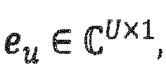
- e u selects the u -th vector for each polarization of the antenna array, and combines them across both polarizations.
- ⁇ 1 is a quantized phase adjustment for the second polarization of the antenna array.
- F 2 ( s ) is given for dual-polarized antenna arrays by [2]
- F 2 s e j ⁇ 1 p 1 ⁇ e j ⁇ 2 U p 2 U ⁇ C U ⁇ 2 ⁇ 1
- F 2 ( s ) contains R vectors, where the entries of each vector are chosen to combine single or multiple beams within each polarization and/or combining them across both polarizations.
- the selection of the matrices F 1 and F 2 ( s ) is performed by the UE based on the knowledge of the current channel conditions.
- the selected matrices are contained in the CSI report in the form of a RI and a PMI and used at the gNB to update the multi-user precoder for the next transmission time interval.
- the CSI reporting rate is related to the channel coherence time which defines the time duration over which the channel is considered to be not varying. This means, in quasi-static channel scenarios, where the UE does not move or moves slowly, the channel coherence time is large and the CSI needs to be less frequently updated. However, if the channel conditions change fast, for example due to a high movement of the UE in a multi-path channel environment, the channel coherence time is short and the transmit signals experience severe fading caused by a Doppler-frequency spread. For such channel conditions, the CSI needs to be updated frequently which causes a high feedback overhead. Especially, for future NR systems (Rel. 16) that are likely to be more multi-user centric, the multiple CSI reports from users in highly-dynamic channel scenarios will drastically reduce the overall efficiency of the communication system.
- explicit CSI refers to reporting of explicit channel coefficients from the UE to the gNB without a codebook for the precoder selection at the UE.
- Those schemes have in common estimating the parameters of the dominant channel taps of the multipath propagation channel as well as their time-evolution at the UE. For example, in [3] each channel tap is modelled as a sum of sub-channel taps where each sub-tap is parameterized with a Doppler-frequency shift and path gain.
- the estimated parameters for each channel tap are fed back to the base station, where they are used with a channel model for time-domain based channel prediction before downlink precoding.
- the availability of explicit CSI comes at an increased overhead for the feedback channel compared to implicit-based channel feedback, especially for slow-varying channels, which is not desired.
- WO 2018/052255 A1 relates to explicit CSI acquisition to represent the channel in wireless communication systems using the principle component analysis (PCA), which is applied on the frequency-domain channel matrix, covariance matrix, or eigenvector of the channel matrix.
- PCA principle component analysis
- a codebook approach for downlink signal precoding at the base station equipped with a two-dimensional array and CSI reporting configuration is proposed.
- an inherent drawback of the proposed CSI reporting scheme is that the CSI report from a user contains only information about the selected CQI, PMI and RI with respect to the current MIMO channel state/realization and does not take into account channel variations over time caused by small-scale channel fading.
- the proposed CSI reporting scheme is restricted to one beam per layer PMI feedback which leads to a limited CSI accuracy and turns out to be insufficient for CSI acquisition in multi-user MIMO.
- CSI-RS resource set(s) which may refer to NZP-CSI-RS, CSI-IM or CSI-SSB resource set(s) [2] is performed using the following higher layer parameters (see reference [4]):
- the CSI-RS design may be used to acquire CSI for a link adaptation (modulation and coding scheme - MCS), and for selecting a precoding matrix from a specific channel realization/snapshot, it cannot track channel evolution in time to estimate Doppler-frequency components of a MIMO channel.
- Embodiments of the present invention may be implemented in a wireless communication system or network as depicted in Fig. 1 or Fig. 2 including transmitters or transceivers, like base stations, and communication devices (receivers) or users, like mobile or stationary terminals or IoT devices, as mentioned above.
- Fig. 3 is a schematic representation of a wireless communication system for communicating information between a transmitter 200, like a base station, and a plurality of communication devices 202 1 to 202 n , like UEs, which are served by the base station 200.
- the base station 200 and the UEs 202 may communicate via a wireless communication link or channel 204, like a radio link.
- the base station 200 includes one or more antennas ANT T or an antenna array having a plurality of antenna elements, and a signal processor 200a.
- the UEs 202 include one or more antennas ANT R or an antenna array having a plurality of antennas, a signal processor 202a 1 , 202a n , and a transceiver 202b 1 , 202b n .
- the base station 200 and the respective UEs 202 may operate in accordance with the inventive teachings described herein.
- the present invention provides a communication device 202 for providing a channel state information, CSI, feedback in a wireless communication system, the communication device 202 comprising:
- the present invention provides a communication device 202 for providing a channel state information, CSI, feedback in a wireless communication system.
- the communication device 202 receives a reference signal resource configuration, e.g., a CSI-RS resource configuration, including a parameter, like a higher layer (e.g., RRC) parameter, e.g., referred to as CSI-RS-BurstDuration, the parameter indicating a time-domain-repetition of the downlink reference signals, e.g., in terms of a number of consecutive slots the downlink reference signals are repeated in.
- the communication device determines the CSI feedback based on the repeated downlink reference signals and reports the determined CSI feedback, e.g., to a transmitter providing the reference signals.
- the Doppler-delay-beam three-stage precoder is based on three separate codebooks, and wherein the three separate codebooks include
- the communication device is configured to report to the transmitter the CSI feedback according to a CSI reporting configuration received from the transmitter, the CSI reporting configuration including, for example, the parameter ReportQuantity, which includes at least one the following values:
- the communication device is configured to receive the following values from the transmitter using Radio Resource Control (RRC) layer or physical layer (L1) parameters:
- RRC Radio Resource Control
- L1 physical layer
- the spatial beam components are configured as follows:
- the delay components are configured as follows:
- the Doppler-frequency components are configured as follows:
- the processor is configured to select a Doppler-delay precoder matrix ( W ) based on a performance metric for e.g., the mutual-information I ( W ; ) , which is a function of the Doppler-delay precoder matrix W and a multi-dimensional channel tensor .
- the processor is configured to select a wideband CQI that optimizes the average block error rate H
- the processor is configured to
- the processor is configured to
- the communication device is configured to receive a CSI reporting configuration comprising a parameter CQI-PredictionTime assigned with the value K which is used by the communication device for CQI prediction.
- the processor is configured to report at least a two-component PMI
- the processor is configured to
- the CSI feedback further includes a rank indicator, RI
- the communication device is configured to receive a CSI-RS resource configuration including a higher layer (e.g., RRC) parameter, e.g., referred to as CSI-RS-BurstDuration, indicating a time-domain-repetition of the downlink reference signals, e.g., in terms of a number of consecutive slots the downlink reference signals are repeated in.
- a higher layer e.g., RRC
- CSI-RS-BurstDuration e.g., referred to as CSI-RS-BurstDuration
- the present invention provides a transmitter 200 in a wireless communication system including a communication device 202, the transmitter comprising:
- the present invention provides a base wireless communication network, comprising at least one of the inventive UEs, and at least one of the inventive base stations.
- the communication device and the transmitter comprises one or more of: a mobile terminal, or stationary terminal, or cellular IoT-UE, or an IoT device, or a ground based vehicle, or an aerial vehicle, or a drone, or a moving base station, or road side unit, or a building, or a macro cell base station, or a small cell base station, or a road side unit, or a UE, or a remote radio head, or an AMF, or an SMF, or a core network entity, or a network slice as in the NR or 5G core context, or any transmission/reception point (TRP) enabling an item or a device to communicate using the wireless communication network, the item or device being provided with network connectivity to communicate using the wireless communication network.
- TRP transmission/reception point
- the present invention provides a method for providing a channel state information, CSI, feedback in a wireless communication system, the method comprising:
- the present invention provides a method for transmitting in a wireless communication system including a communication device and a transmitter, the method comprising:
- the present invention provides a computer program product comprising instructions which, when the program is executed by a computer, causes the computer to carry out one or more methods in accordance with the present invention.
- embodiments of the present invention provides for an extension of the existing CSI-RS to track the channel time-evolution, e.g., for a channel having channel conditions which change fast, for example due to a high movement of the UE in a multi-path channel environment, and having a short channel coherence time.
- the present invention is advantageous as by tracking the channel time-evolution, even for channels with varying channel conditions, the CSI needs not to be updated less frequently, e.g., with a rate similar for channels with a long channel coherence time, thereby reducing or avoiding a feedback overhead.
- the large-scale channel parameters such as path loss and shadow fading may not change quickly over time, even in a channel having a short channel coherence time, so that the channel variations are mainly related to small scale channel fading.
- the MIMO channel parameters of the impulse response such as path components and channel delays do not change over a longer time period, and channel variations caused by movement of the UE lead only to phase fluctuations of the MIMO channel path components.
- the spatial beams, the precoder Doppler-frequency DFT-vectors, the delay DFT-vectors as well as the Doppler-delay coefficients of the Doppler-delay-beam three-stage precoder remain identical or substantially identical for a long time period, and need to be less frequently updated.
- embodiments of the present invention provide a CSI-RS design allowing track time-evolution of CSI or a new implicit CSI reporting scheme that takes into account the channel time-evolution and provides information about current and future RI, PMI and CQI in a compressed form to reduce the feedback rate.
- Fig. 4 is a flow diagram illustrating the configuration of CSI parameters, the CSI measurement, the composite precoder matrix calculation and the CSI reporting in accordance with an embodiment of the present invention.
- the UE may be configured with a CSI-RS resource configuration via a higher layer (such as RRC) containing information about the number of assigned CSI-RS ports used for the transmission to the UE.
- the UE is configured with a CSI reporting configuration via a higher layer and/or a physical layer (via DCI) that also contains information for an evaluation of the CSI feedback parameters, such as CQI, RI and PMI, at the UE.
- the base station or gNB signals via a higher layer or a physical layer at least five integer values for ( N 1 ,N 2 ,P ) , S, and T, where ( N 1 ,N 2 ,P ) are used to configure a first codebook, and S and T are used to configure a second codebook and a third codebook, respectively, for the PMI decomposition/calculation at the UE.
- the CQI, RI and PMI selection is performed at the UE according to the subsequently described embodiments.
- the gNB or base station sends a CSI-RS configuration and CSI report configuration to the UE.
- the CSI-RS configuration may include a CSI-RS resource(s) configuration with respect to sub-clause 7.4.1.5 in TS 38.211 [1] and with sub-clause 6.3.2 in TS.38.331 [4].
- an additional higher layer parameter configuration referred to as CSI-RS-BurstDuration is included.
- the CSI-RS-BurstDuration is included to provide a CSI-RS design allowing to track the time-evolution of the channel.
- a UE is configured with a CSI-RS resource set(s) configuration with the higher layer parameter CSI-RS-BurstDuration, in addition to the configurations from clause 7.4.1.5 in TS 38.211 [2] and clause 6.3.2 in TS.38.331 [4] mentioned above, to track the time-evolution of CSI.
- the time-domain-repetition of the CSI-RS in terms of the number of consecutive slots the CSI-RS is repeated in, is provided by the higher layer parameter CSI-RS-BurstDuration.
- the possible values of CSI-RS-BurstDuration for the NR numerology ⁇ are 2 ⁇ ⁇ X B slots, where X B ⁇ ⁇ 0,1,2, ...,maxNumBurstSlots - 1 ⁇ .
- the NR numerology ⁇ 0,1,2,3,4 ... defines, e.g., a subcarrier spacing of 2 ⁇ ⁇ 15kHz in accordance with the NR standard.
- CSI-RS-BurstDuration 4
- the information element of the new RRC parameter CSI-RS-BurstDuration is as follows: the value next to the text burstSlots indicates the value of X B , which for a given New Radio numerology ⁇ (see [1]) provides the burst duration 2 ⁇ ⁇ X B of the CSI-RS, i.e., the number of consecutive slots of CSI-RS repetition.
- the burst-CSI-RS across multiple consecutive slots enables the extraction of time-evolution information of the CSI and for reporting of the precoder matrix, e.g. as a part of the PMI, in a way as described in more detail below.
- the UE may calculate the CQI, RI and PMI according to the embodiments described below with a repetition of the CSI-RS resource(s) over multiple consecutive slots, and report them accordingly.
- the CSI report configuration provided by the eNB may further include one or more of at least the following parameters:
- the CQI value, predicted CQI value, etc. (if configured) as mentioned in the reporting quantity may be calculated as explained in subsequently described embodiments over multiple time slots.
- the values of the CQI reported are identical as mentioned in TS 38.214 [2].
- the following parameters may be signaled by the eNB to the user equipment via physical layer or higher layer (RRC) parameters:
- the gNB reconstructs the Doppler-delay-beam composite three-stage precoder matrix (PMI report) to facilitate multi-user precoding matrix calculation and precoder matrix prediction for future time instants.
- PMI report the Doppler-delay-beam composite three-stage precoder matrix
- inventions of the inventive approach operating on the basis of repeated downlink reference signals may use other precoders or other techniques to determine the CSI feedback based on the repeated downlink reference signals and to report determine the CSI feedback.
- the UE estimates an un-quantized explicit CSI using measurements on the downlink CSI-RS on PRBs, where the CSI-RS is configured over T consecutive time instants/slots in the frequency domain (see step 252 in Fig. 4 ).
- the first, second and third dimension of the channel tensor represent the space, frequency, and time component of the time-variant frequency-selective MIMO channel, respectively.
- the first and second dimension of represent the receive-side and transmit-side space components of the time-variant frequency-selective MIMO channel, respectively.
- the third and fourth dimension of represent the frequency and time component of the MIMO channel, respectively.
- the UE calculates a CQI using the explicit CSI in the form of the channel tensor and a composite Doppler-delay-beam three-stage precoder constructed using three separate codebooks:
- the above mentioned beam, delay and Doppler-frequency components may be included into a single or common codebook, or two of the above mentioned beam, delay and Doppler-frequency components are included in one codebook, and the remaining component is included in another codebook.
- FIG. 8 A structure of the Doppler-delay-beam composite precoder matrix is shown in Fig. 8 , which illustrates the composite Doppler-delay-beam precoder matrix of size N t ⁇ T ⁇ S .
- the values for the number of beams, delays, and Doppler-frequency components U l D u l F d , u l are configured via a higher layer (e.g., RRC, or MAC) signaling or as a part of the DCI (physical layer signaling) in the downlink grant from the gNB to the UE.
- the UE reports the preferred values of U l D u l F d , u l as a part of the CSI report.
- the values of U l D u l F d , u l are known a-priori by the UE.
- the delay components are configured in different ways, as will now be described.
- the delay components configuration as explained above may be configured via a higher layer (e.g., RRC, or MAC) signaling or may be configured as a part of DCI (physical layer signaling) in the downlink grant from the gNB to the UE.
- the delay configuration may be a-priori known by the UE.
- the Doppler-frequency components are configured in different ways, as will now be described.
- the Doppler-frequency components configuration as explained above may be configured via a higher layer (e.g., RRC, or MAC) signaling or may be configured as a part of DCI (physical layer signaling) in the downlink grant from the gNB to the UE.
- the Doppler-frequency configuration may be a-priori known by the UE.
- the vectors (spatial beams) b u l are selected from an oversampled DFT-codebook matrix ⁇ 1 of size N 1 N 2 ⁇ O 1,1 N 1 O 1,2 N 2 .
- the DFT-codebook matrix is parameterized by the two oversampling factors O 1,1 ⁇ ⁇ 1,2,3,.. ⁇ and O 1,2 ⁇ ⁇ 1,2,3,.. ⁇ .
- Each entry in the codebook matrix is associated with a specific delay.
- Each entry in the codebook matrix is associated with a specific Doppler-frequency.
- the oversampled factors O 1,1 , O 1,2 , O 2 , O 3 of the DFT-codebook matrices may be configured via a higher layer (e.g., RRC, or MAC) signaling or may be configured as a part of the DCI (physical layer signaling) in the downlink grant from the gNB to the UE.
- the oversampled factors O 1,1 , O 1,2 , O 2 , O 3 of the DFT-codebook matrices may be known by the UE.
- the UE selects a preferred Doppler-delay precoder matrix W based on a performance metric (see step 256 in Fig. 4 ).
- the UE selects the precoder matrix W that optimizes the mutual-information I ( W ; ) , which is a function of the Doppler-delay precoder matrix W and the multi-dimensional channel tensor , for each configured SB, PRB, or subcarrier.
- the UE calculates the beam-formed channel tensor of dimension 2 UN r ⁇ S ⁇ T with the U spatial beams b ⁇ 1 1 , ... , b ⁇ U 1 .
- the UE selects three-tuples of Doppler-frequency DFT-vectors, delay DFT-vectors and Doppler-delay-beam combining coefficients, where the Doppler-frequency and delay DFT-vectors are selected from the codebooks ⁇ 3 and ⁇ 2 , respectively, such that the mutual information I H ⁇ ; W
- the UE may select the rank indicator, RI, for reporting (see step 258 in Fig. 4 ).
- RI reporting is configured at the UE
- the UE reports a rank indicator (total number of layers) for the transmission.
- the UE may select the channel quality indicator, CQI, for reporting (see step 258 in Fig. 4 ).
- CQI reporting is configured at the UE, the UE reports a preferred CQI based on a specific performance metric such as signal-to-interference and noise ratio (SINR), average bit error rate, average throughput, etc.
- SINR signal-to-interference and noise ratio
- the UE may select the CQI that optimizes the average block error rate block_error_rate (
- the CQI value represents an "average" CQI supported by the Doppler-delay-beam precoded time-variant frequency-selective MIMO channel.
- the UE may select the precoder matrix indicator, PMI, for reporting (see step 258 in Fig. 4 ).
- PMI reporting is configured at the UE, the UE reports at least a two-component PMI.
- the first PMI component may correspond to the selected vectors b u l , d p , u , d l and f p , u , d , v l , and may be represented in the form of three-tuple' sets, where each three-tuple ( u , d , v ) is associated with a selected spatial beam vector b u l , a selected delay vector d p , u , d l , and a selected Doppler-frequency vector f p , u , d , v l .
- i 1,1 contains ⁇ l U ( l ) indices of selected DFT-vectors for the spatial beams
- i 1,2 contains 2 ⁇ u , l D u l indices of selected delay-vectors
- i 1,3 contains 2 ⁇ u , d , l F d , u l indices of selected Doppler-frequency-vectors.
- Fig. 9 shows an example for i 1 for a layer-1 transmission.
- the subset i 1,1 of i 1 represents the beam indices selected from the codebook ⁇ 1 and are denoted by a u , ⁇ u .
- the subset i 1,2 of i 1 represents the delay indices selected from the codebook ⁇ 2 and are denoted by c d,u , ⁇ d, u.
- the subset i 1,3 of i 1 represents the selected Doppler-frequency indices from the codebook ⁇ 3 and are denoted by e v,d,u , ⁇ v , d,u .
- the UE may quantize the coefficients using a codebook approach.
- the quantized combining coefficients are represented by i 2 , the second PMI.
- the two PMIs are reported to the gNB.
- the large-scale channel parameters such as path loss and shadow fading do not change quickly over time, and the channel variations are mainly related to small scale channel fading.
- the precoder matrix information is used to calculate a multi-user precoding matrix which is applied to the transmission signals to adapt the transmission parameters to the current multiuser channel conditions.
- the above Doppler-delay composite Kronecker-based precoder matrix definition also facilitates the prediction of precoder matrices for future time instances. In this way, the number of CSI reports may be drastically reduced and feedback overhead is saved.
- the Doppler-frequency DFT-vectors f p , u , d , v l may be cyclically extended to length- QT vectors t p , u , d , v l .
- the predicted precoding matrices may be used in predictive multi-user scheduling algorithms that attempt to optimize, for example, the throughput for all users by using the knowledge of current and future precoder matrices of the users.
- the UE may be configured to quantize the complex Doppler-delay coefficients ⁇ p , u , d , v l with a codebook approach.
- the UE may be configured to predict a CQI value for time-instant/slot " n + K " , where n denotes the current time-instant/slot, and K denotes the relative time difference with respect to the current time-instant/slot n .
- the UE uses in a first step a high resolution parameter estimation algorithm, such as RIMAX (see reference [5]), to estimate parameters of a channel model directly from the multi-dimensional channel tensor .
- a high resolution parameter estimation algorithm such as RIMAX (see reference [5])
- the time-variant MIMO channel model impulse response may be defined by a number of channel taps, where each channel tap is parameterized with a channel gain, Doppler-frequency shift and a delay.
- the coefficients of H ( t,w ) may also be calculated directly in a non-parameterized form from the MIMO channel tensor by using a linear block-filtering approach such as least squares or minimum-mean-squared-error (MMSE) filtering (see references [6] and [7]).
- MMSE minimum-mean-squared-error
- the channel predictor is formed by a weighted sum of the MIMO channel tensor .
- the UE uses the parameterized precoded MIMO channel model response to calculate a CQI value for a future time instant n + K, i.e., the CQI( n + K ) is expressed as a function of H prec ( n + K, w ) .
- the K predicted CQI values may be used to calculate differential predicted CQI values by reducing the K predicted CQI values by the "average" CQI value.
- the predicted single CQI value, or predicted K CQI values, or predicted K differential CQI values is/are reported to the gNB.
- a communication device for providing a channel state information, CSI, feedback in a wireless communication system, wherein the communication device receives a CSI-RS resource configuration including a higher layer (e.g., RRC) parameter, e.g., referred to as CSI-RS-BurstDuration, indicating a time-domain-repetition of the downlink reference signals, e.g., in terms of a number of consecutive slots the downlink reference signals are repeated in.
- the communication device determines the CSI feedback based on the repeated downlink reference signals and reports the determined CSI feedback.
- the UE may be configured with a CSI-RS reporting configuration via a higher layer for reporting a CQI, RI and PMI (if configured) for beam-formed CSI-RS.
- the corresponding PDSCH signals [ y ( t ,3000) ( i ) ⁇ y ( t ,3000+ P -1) ( i )] transmitted on antenna ports [3000,3000 + P - 1] have a ratio of, energy per resource element, EPRE, to CSI-RS EPRE equal to the ratio given in Subclause 4.1 of TS 38.214 [2].
- the precoder matrix is kept constant over time until it is updated by a reported PMI.
- the approach in accordance with embodiments takes into account the channel variations by updating the precoder matrix continuously over time without instantaneous PMI reporting.
- the wireless communication system may include a terrestrial network, or a non-terrestrial network, or networks or segments of networks using as a receiver an airborne vehicle or a spaceborne vehicle, or a combination thereof.
- the UE may comprise one or more of a mobile or stationary terminal, an loT device, a ground based vehicle, an aerial vehicle, a drone, a building, or any other item or device provided with network connectivity enabling the item/device to communicate using the wireless communication system, like a sensor or actuator.
- the base station may comprise one or more of a macro cell base station, or a small cell base station, or a spaceborne vehicle, like a satellite or a space, or an airborne vehicle, like a unmanned aircraft system (UAS), e.g., a tethered UAS, a lighter than air UAS (LTA), a heavier than air UAS (HTA) and a high altitude UAS platforms (HAPs), or any transmission/reception point (TRP) enabling an item or a device provided with network connectivity to communicate using the wireless communication system.
- UAS unmanned aircraft system
- LTA lighter than air UAS
- HTA heavier than air UAS
- HAPs high altitude UAS platforms
- TRP transmission/reception point
- the embodiments of the present invention have been described above with reference to a communication system employing a rank 1 or layer 1 communication. However, the present invention is not limited to such embodiments and may also be implemented in a communication system employing a higher rank or layer communication.
- the feedback includes the delays per layer and the complex precoder coefficients per layer.
- the embodiments of the present invention have been described above with reference to a communication system in which the transmitter is a base station serving a user equipment, and the communication device or receiver is the user equipment served by the base station.
- the present invention is not limited to such embodiments and may also be implemented in a communication system in which the transmitter is a user equipment station, and the communication device or receiver is the base station serving the user equipment.
- the communication device and the transmitter may both be UEs communicating via directly, e.g., via a sidelink interface.
- aspects of the described concept have been described in the context of an apparatus, it is clear that these aspects also represent a description of the corresponding method, where a block or a device corresponds to a method step or a feature of a method step. Analogously, aspects described in the context of a method step also represent a description of a corresponding block or item or feature of a corresponding apparatus.
- Various elements and features of the present invention may be implemented in hardware using analog and/or digital circuits, in software, through the execution of instructions by one or more general purpose or special-purpose processors, or as a combination of hardware and software.
- embodiments of the present invention may be implemented in the environment of a computer system or another processing system.
- Fig. 11 illustrates an example of a computer system 350.
- the units or modules as well as the steps of the methods performed by these units may execute on one or more computer systems 350.
- the computer system 350 includes one or more processors 352, like a special purpose or a general purpose digital signal processor.
- the processor 352 is connected to a communication infrastructure 354, like a bus or a network.
- the computer system 350 includes a main memory 356, e.g., a random access memory (RAM), and a secondary memory 358, e.g., a hard disk drive and/or a removable storage drive.
- the secondary memory 358 may allow computer programs or other instructions to be loaded into the computer system 350.
- the computer system 350 may further include a communications interface 360 to allow software and data to be transferred between computer system 350 and external devices.
- the communication may be in the from electronic, electromagnetic, optical, or other signals capable of being handled by a communications interface.
- the communication may use a wire or a cable, fiber optics, a phone line, a cellular phone link, an RF link and other communications channels 362.
- computer program medium and “computer readable medium” are used to generally refer to tangible storage media such as removable storage units or a hard disk installed in a hard disk drive.
- These computer program products are means for providing software to the computer system 350.
- the computer programs also referred to as computer control logic, are stored in main memory 356 and/or secondary memory 358. Computer programs may also be received via the communications interface 360.
- the computer program when executed, enables the computer system 350 to implement the present invention.
- the computer program when executed, enables processor 352 to implement the processes of the present invention, such as any of the methods described herein. Accordingly, such a computer program may represent a controller of the computer system 350.
- the software may be stored in a computer program product and loaded into computer system 350 using a removable storage drive, an interface, like communications interface 360.
- the implementation in hardware or in software may be performed using a digital storage medium, for example cloud storage, a floppy disk, a DVD, a Blue-Ray, a CD, a ROM, a PROM, an EPROM, an EEPROM or a FLASH memory, having electronically readable control signals stored thereon, which cooperate (or are capable of cooperating) with a programmable computer system such that the respective method is performed. Therefore, the digital storage medium may be computer readable.
- a digital storage medium for example cloud storage, a floppy disk, a DVD, a Blue-Ray, a CD, a ROM, a PROM, an EPROM, an EEPROM or a FLASH memory, having electronically readable control signals stored thereon, which cooperate (or are capable of cooperating) with a programmable computer system such that the respective method is performed. Therefore, the digital storage medium may be computer readable.
- Some embodiments according to the invention comprise a data carrier having electronically readable control signals, which are capable of cooperating with a programmable computer system, such that one of the methods described herein is performed.
- embodiments of the present invention may be implemented as a computer program product with a program code, the program code being operative for performing one of the methods when the computer program product runs on a computer.
- the program code may for example be stored on a machine readable carrier.
- inventions comprise the computer program for performing one of the methods described herein, stored on a machine readable carrier.
- an embodiment of the inventive method is, therefore, a computer program having a program code for performing one of the methods described herein, when the computer program runs on a computer.
- a further embodiment of the inventive methods is, therefore, a data carrier (or a digital storage medium, or a computer-readable medium) comprising, recorded thereon, the computer program for performing one of the methods described herein.
- a further embodiment of the inventive method is, therefore, a data stream or a sequence of signals representing the computer program for performing one of the methods described herein. The data stream or the sequence of signals may for example be configured to be transferred via a data communication connection, for example via the Internet.
- a further embodiment comprises a processing means, for example a computer, or a programmable logic device, configured to or adapted to perform one of the methods described herein.
- a further embodiment comprises a computer having installed thereon the computer program for performing one of the methods described herein.
- a programmable logic device for example a field programmable gate array
- a field programmable gate array may cooperate with a microprocessor in order to perform one of the methods described herein.
- the methods are preferably performed by any hardware apparatus.
Landscapes
- Engineering & Computer Science (AREA)
- Signal Processing (AREA)
- Computer Networks & Wireless Communication (AREA)
- Physics & Mathematics (AREA)
- Mathematical Physics (AREA)
- Power Engineering (AREA)
- Quality & Reliability (AREA)
- Electromagnetism (AREA)
- Mobile Radio Communication Systems (AREA)
- Radio Transmission System (AREA)
Abstract
A communication device for providing a channel state information, CSI, feedback in a wireless communication system includes a transceiver to receive, from a transmitter a radio signal via a time-variant, frequency-selective MIMO channel, the radio signal including downlink reference signals according to a reference signal configuration comprising a number of antenna ports, and downlink signals comprising the reference signal configuration; and a processor. The processor estimates an explicit CSI in the frequency domain using measurements on the downlink reference signals on the radio channel, the downlink reference signals provided over a certain observation time, selects, based on a performance metric, a Doppler-delay precoder matrix (W) for a composite Doppler-delay-beam three-stage precoder, the Doppler-delay-beam three-stage precoder being based on one or more codebooks, the one or more codebooks including one or more transmit-side spatial beam components of the composite Doppler-delay-beam three-stage precoder, one or more delay components of the composite Doppler-delay-beam three-stage precoder, and one or more Doppler-frequency components of the composite Doppler-delay-beam three-stage precoder, calculates either one or more of a channel quality indicator, CQI, and/or a precoder matrix indicator, PMI, and/or a rank indicator, RI, using the explicit CSI and the composite Doppler-delay-beam three-stage precoder with the selected Doppler-delay-beam precoder matrix (W), and reports to the transmitter the CSI feedback including either one or more of the CQI, and/or the PMI and/or the RI, wherein the PMI and RI are used to indicate the Doppler-delay-beam three-stage composite precoder matrix for the configured antenna ports.
Description
- The present application concerns the field of wireless communications, more specifically to wireless communication systems employing precoding using Doppler-delay codebook-based precoding and channel state information, CSI, reporting.
-
Fig. 1 is a schematic representation of an example of a terrestrialwireless network 100 including acore network 102 and aradio access network 104. Theradio access network 104 may include a plurality of base stations gNB1 to gNB5, each serving a specific area surrounding the base station schematically represented by respective cells 1061 to 1065. The base stations are provided to serve users within a cell. The term base station, BS, refers to as gNB in 5G networks, eNB in UMTS/LTE/LTE-A/ LTE-A Pro, or just BS in other mobile communication standards. A user may be a stationary device or a mobile device. Further, the wireless communication system may be accessed by mobile or stationary loT devices which connect to a base station or to a user. The mobile devices or the loT devices may include physical devices, ground based vehicles, such as robots or cars, aerial vehicles, such as manned or unmanned aerial vehicles (UAVs), the latter also referred to as drones, buildings and other items or devices having embedded therein electronics, software, sensors, actuators, or the like as well as network connectivity that enable these devices to collect and exchange data across an existing network infrastructure.Fig. 1 shows an exemplary view of only five cells, however, the wireless communication system may include more such cells.Fig. 1 shows two users UE1 and UE2, also referred to as user equipment, UE, that are in cell 1062 and that are served by base station gNB2. Another user UE3 is shown in cell 1064 which is served by base station gNB4. Thearrows Fig. 1 shows twoIoT devices loT device 1101 accesses the wireless communication system via the base station gNB4 to receive and transmit data as schematically represented by arrow 1121. TheloT device 1102 accesses the wireless communication system via the user UE3 as is schematically represented by arrow 1122. The respective base station gNB1 to gNB5 may be connected to thecore network 102, e.g. via the S1 interface, viarespective backhaul links 1141 to 1145, which are schematically represented inFig. 1 by the arrows pointing to "core". Thecore network 102 may be connected to one or more external networks. Further, some or all of the respective base station gNB1 to gNB5 may connected, e.g. via the S1 or X2 interface or XN interface in NR, with each other viarespective backhaul links 1161 to 1165, which are schematically represented inFig. 1 by the arrows pointing to "gNBs". The wireless network or communication system depicted inFig. 1 may by an heterogeneous network having two distinct overlaid networks, a network of macro cells with each macro cell including a macro base station, like base station gNB1 to gNB5, and a network of small cell base stations (not shown inFig. 1 ), like femto or pico base stations. - For data transmission a physical resource grid may be used. The physical resource grid may comprise a set of resource elements to which various physical channels and physical signals are mapped. For example, the physical channels may include the physical downlink and uplink shared channels (PDSCH, PUSCH) carrying user specific data, also referred to as downlink and uplink payload data, the physical broadcast channel (PBCH) carrying for example a master information block (MIB) and a system information block (SIB), the physical downlink and uplink control channels (PDCCH, PUCCH) carrying for example the downlink control information (DCI), etc. For the uplink, the physical channels may further include the physical random access channel (PRACH or RACH) used by UEs for accessing the network once a UE synchronized and obtained the MIB and SIB. The physical signals may comprise reference signals or symbols (RS), synchronization signals and the like. The resource grid may comprise a frame or radio frame having a certain duration, like 10 milliseconds, in the time domain and having a given bandwidth in the frequency domain. The frame may have a certain number of subframes of a predefined length, e.g., 2 subframes with a length of 1 millisecond. Each subframe may include two slots of 6 or 7 OFDM symbols depending on the cyclic prefix (CP) length. A frame may also consist of a smaller number of OFDM symbols, e.g. when utilizing shortened transmission time intervals (sTTI) or a mini-slot/non-slot-based frame structure comprising just a few OFDM symbols.
- The wireless communication system may be any single-tone or multicarrier system using frequency-division multiplexing, like the orthogonal frequency-division multiplexing (OFDM) system, the orthogonal frequency-division multiple access (OFDMA) system, or any other IFFT-based signal with or without CP, e.g. DFT-s-OFDM. Other waveforms, like non-orthogonal waveforms for multiple access, e.g. filter-bank multicarrier (FBMC), generalized frequency division multiplexing (GFDM) or universal filtered multi carrier (UFMC), may be used. The wireless communication system may operate, e.g., in accordance with the LTE-Advanced pro standard or the 5G or NR, New Radio, standard.
- In the wireless communication network as shown in
Fig. 1 theradio access network 104 may be a heterogeneous network including a network of primary cells, each including a primary base station, also referred to as a macro base station. Further, a plurality of secondary base stations, also referred to as small cell base stations, may be provided for each of the macro cells. In addition to the above described terrestrial wireless network also non-terrestrial wireless communication networks exist including spaceborne transceivers, like satellites, and/or airborne transceivers, like unmanned aircraft systems. The non-terrestrial wireless communication network or system may operate in a similar way as the terrestrial system described above with reference toFig. 1 , for example in accordance with the LTE-advanced pro standard or the 5G or NR, new radio, standard. - In a wireless communication system like to one depicted schematically in
Fig. 1 , multi-antenna techniques may be used, e.g., in accordance with LTE or NR, to improve user data rates, link reliability, cell coverage and network capacity. To support multi-stream or multilayer transmissions, linear precoding is used in the physical layer of the communication system. Linear precoding is performed by a precoder matrix which maps layers of data to antenna ports. The precoding may be seen as a generalization of beamforming, which is a technique to spatially direct/focus data transmission towards an intended receiver. The precoder matrix to be used at the gNB to map the data to the transmit antenna ports is decided using channel state information, CSI. - In a communication system as described above, such as LTE or New Radio (5G), downlink signals convey data signals, control signals containing down link, DL, control information (DCI), and a number of reference signals or symbols (RS) used for different purposes. A gNodeB (or gNB or base station) transmits data and control information (DCI) through the so-called physical downlink shared channel (PDSCH) and physical downlink control channel (PDCCH) or enhanced PDCCH (ePDCCH), respectively. Moreover, the downlink signal(s) of the gNB may contain one or multiple types of RSs including a common RS (CRS) in LTE, a channel state information RS (CSI-RS), a demodulation RS (DM-RS), and a phase tracking RS (PT-RS). The CRS is transmitted over a DL system bandwidth part, and used at the user equipment (UE) to obtain a channel estimate to demodulate the data or control information. The CSI-RS is transmitted with a reduced density in the time and frequency domain compared to CRS, and used at the UE for channel estimation/ channel state information (CSI) acquisition. The DM-RS is transmitted only in a bandwidth part of the respective PDSCH and used by the UE for data demodulation. For signal precoding at the gNB, several CSI-RS reporting mechanism were introduced such as non-precoded CSI-RS and beamformed CSI-RS reporting (see reference [1]). For a non-precoded CSI-RS, a one-to-one mapping between a CSI-RS port and a transceiver unit, TXRU, of the antenna array at the gNB is utilized. Therefore, non-precoded CSI-RS provides a cell-wide coverage where the different CSI-RS ports have the same beam-direction and beam-width. For beamformed/precoded UE-specific or non-UE-specific CSI-RS, a beam-forming operation is applied over a single- or multiple antenna ports to have several narrow beams with high gain in different directions and therefore, no cell-wide coverage.
- In a wireless communication system employing time division duplexing, TDD, due to channel reciprocity, the channel state information (CSI) is available at the base station (gNB). However, when employing frequency division duplexing, FDD, due to the absence of channel reciprocity, the channel has to be estimated at the UE and feed back to the gNB.
Fig. 2 shows a block-based model of a MIMO DL transmission using codebook-based-precoding in accordance withLTE release 8.Fig. 2 shows schematically thebase station 200, gNB, the user equipment, UE, 202 and thechannel 204, like a radio channel for a wireless data communication between thebase station 200 and theuser equipment 202. The base station includes an antenna array ANTT having a plurality of antennas or antenna elements, and aprecoder 206 receiving adata vector 208 and a precoder matrix F from acodebook 210. Thechannel 204 may be described by the channel tensor/matrix 212. Theuser equipment 202 receives thedata vector 214 via an antenna or an antenna array ANTR having a plurality of antennas or antenna elements. Afeedback channel 216 between theuser equipment 202 and thebase station 200 is provided for transmitting feedback information. The previous releases of 3GPP up to Rel.15 support the use of several downlink reference symbols (such as CSI-RS) for CSI estimation at the UE. In FDD systems (up to Rel. 15), the estimated channel at the UE is reported to the gNB implicitly where the CSI transmitted by the UE over the feedback channel includes the rank index (RI), the precoding matrix index (PMI) and the channel quality index (CQI) (and the CRI from Rel. 13) allowing, at the gNB, deciding the precoding matrix, and the modulation order and coding scheme (MCS) of the symbols to be transmitted. The PMI and the RI are used to determine the precoding matrix from a predefined set of matrices Ω called 'codebook'. The codebook, e.g., in accordance with LTE, may be a look-up table with matrices in each entry of the table, and the PMI and RI from the UE decide from which row and column of the table the precoder matrix to be used is obtained. The precoders and codebooks are designed up to Rel. 15 for gNBs equipped with one-dimensional Uniform Linear Arrays (ULAs) having N 1 dual-polarized antennas (in total Nt = 2N 1 antennas), or with two-dimensional Uniform Planar Arrays (UPAs) having dual-polarized antennas at N 1 N 2 positions (in total N t = 2N 1 N 2 antennas). The ULA allows controlling the radio wave in the horizontal (azimuth) direction only, so that azimuth-only beamforming at the gNB is possible, whereas the UPA supports transmit beamforming on both vertical (elevation) and horizontal (azimuth) directions, which is also referred to as full-dimension (FD) MIMO. The codebook, e.g., in the case of massive antenna arrays such as FD-MIMO, may be a set of beamforming weights that forms spatially separated electromagnetic transmit/receive beams using the array response vectors of the array. The beamforming weights (also referred to as the 'array steering vectors') of the array are amplitude gains and phase adjustments that are applied to the signal fed to the antennas (or the signal received from the antennas) to transmit (or obtain) a radiation towards (or from) a particular direction. The components of the precoder matrix are obtained from the codebook, and the PMI and the RI are used to 'read' the codebook and obtain the precoder. The array steering vectors may be described by the columns of a 2D Discrete Fourier Transform (DFT) matrix when ULAs or UPAs are used for signal transmission. - The precoder matrices used in the Type-I and Type-II CSI reporting schemes in 3GPP New Radio Rel. 15 are defined in frequency-domain and have a dual-stage structure: F (s) = F 1 F 2(s), s = 0...,S - 1 (see reference [2]), where S denotes the number of subbands. The matrix F 1 is a wide-band matrix, independent on index s, and contains U spatial beamforming vectors (the so-called spatial beams)


- The matrix F 2(s), is a selection/combining/co-phasing matrix that selects/combines/co-phases the beams defined in F1 for the s-th configured sub-band.
- For example, for a rank-1 transmission and Type-I CSI reporting, F 2(s) is given for a dual-polarized antenna array by [2]

- For example, for a rank-1 transmission and Type-II CSI reporting, F 2(s) is given for dual-polarized antenna arrays by [2]

- For rank-R transmission, F 2(s) contains R vectors, where the entries of each vector are chosen to combine single or multiple beams within each polarization and/or combining them across both polarizations.
- The selection of the matrices F 1 and F 2(s) is performed by the UE based on the knowledge of the current channel conditions. The selected matrices are contained in the CSI report in the form of a RI and a PMI and used at the gNB to update the multi-user precoder for the next transmission time interval.
- An inherent drawback of the current CSI reporting formats described in [2] for the implicit feedback scheme is that the RI and PMI only contain information of the current channel conditions. Consequently, the CSI reporting rate is related to the channel coherence time which defines the time duration over which the channel is considered to be not varying. This means, in quasi-static channel scenarios, where the UE does not move or moves slowly, the channel coherence time is large and the CSI needs to be less frequently updated. However, if the channel conditions change fast, for example due to a high movement of the UE in a multi-path channel environment, the channel coherence time is short and the transmit signals experience severe fading caused by a Doppler-frequency spread. For such channel conditions, the CSI needs to be updated frequently which causes a high feedback overhead. Especially, for future NR systems (Rel. 16) that are likely to be more multi-user centric, the multiple CSI reports from users in highly-dynamic channel scenarios will drastically reduce the overall efficiency of the communication system.
- To overcome this problem, several explicit CSI feedback schemes have been proposed that take into account the channel-evolution over time (see reference [3]). Here, explicit CSI refers to reporting of explicit channel coefficients from the UE to the gNB without a codebook for the precoder selection at the UE. Those schemes have in common estimating the parameters of the dominant channel taps of the multipath propagation channel as well as their time-evolution at the UE. For example, in [3] each channel tap is modelled as a sum of sub-channel taps where each sub-tap is parameterized with a Doppler-frequency shift and path gain. The estimated parameters for each channel tap are fed back to the base station, where they are used with a channel model for time-domain based channel prediction before downlink precoding. The availability of explicit CSI comes at an increased overhead for the feedback channel compared to implicit-based channel feedback, especially for slow-varying channels, which is not desired.
- For example,
WO 2018/052255 A1 relates to explicit CSI acquisition to represent the channel in wireless communication systems using the principle component analysis (PCA), which is applied on the frequency-domain channel matrix, covariance matrix, or eigenvector of the channel matrix. Thus, a codebook approach for downlink signal precoding at the base station equipped with a two-dimensional array and CSI reporting configuration is proposed. However, an inherent drawback of the proposed CSI reporting scheme is that the CSI report from a user contains only information about the selected CQI, PMI and RI with respect to the current MIMO channel state/realization and does not take into account channel variations over time caused by small-scale channel fading. Therefore, when users experience fast-fading channel conditions, a frequent CSI update is needed which causes a high feedback overhead over time. Moreover, the proposed CSI reporting scheme is restricted to one beam per layer PMI feedback which leads to a limited CSI accuracy and turns out to be insufficient for CSI acquisition in multi-user MIMO. - Moreover, to track channel-evolution over time, the reference signal need be spread over time. In the current 3GPP NR specification [1], a single shot CSI-RS is configured at a particular time slot. Such slots of CSI-RS are periodically transmitted, or triggered on demand. The configuration of a CSI-RS resource set(s) which may refer to NZP-CSI-RS, CSI-IM or CSI-SSB resource set(s) [2] is performed using the following higher layer parameters (see reference [4]):
- CSI-ResourceConfig - The resource set(s) configuration consists of the IDs of the resources configured in the resource set(s), the type of each CSI-RS resource in terms of its periodicity, and the bandwidth part they are configured in.
- CSI-ResourcePeriodicityAndOffset - Mentions the periodicity of a CSI-RS resource in terms of number of slots and offset of CSI-RS.
- CSI-RS-ResourceMapping - Mentions the resource elements in the time-frequency map the CSI-RS resource is mapped to, number of CSI-RS ports, the CDM type used for the mapped reference symbols, and the density and bandwidth of occupancy of the reference symbols in the frequency domain.
- ∘ frequencyDomainAllocation
- ∘ nrofPorts
- ∘ firstOFDMSymbollnTimeDomain
- ∘ firstOFDMSymbollnTimeDomain2
- ∘ cdm-Type
- ∘ density
- ∘ freqBand
- While the CSI-RS design may be used to acquire CSI for a link adaptation (modulation and coding scheme - MCS), and for selecting a precoding matrix from a specific channel realization/snapshot, it cannot track channel evolution in time to estimate Doppler-frequency components of a MIMO channel.
- It is noted that the information in the above section is only for enhancing the understanding of the background of the invention and therefore it may contain information does not form prior art that is already known to a person of ordinary skill in the art.
- It is an object of the present invention to provide an improved approach for CSI reporting allowing to track the channel time-evolution.
- This object is achieved by the subject matter as defined in the independent claims.
- Embodiments are defined in the dependent claims.
- Embodiments of the present invention are now described in further detail with reference to the accompanying drawings, in which:
- Fig. 1
- shows a schematic representation of an example of a wireless communication system;
- Fig. 2
- shows a block-based model of a MIMO DL transmission using codebook-based-precoding in accordance with
LTE release 8; - Fig. 3
- is a schematic representation of a wireless communication system for communicating information between a transmitter, which may operate in accordance with the inventive teachings described herein, and a plurality of receivers, which may operate in accordance with the inventive teachings described herein;
- Fig. 4
- is a flow diagram illustrating the configuration of CSI parameters, the CSI measurement, the composite precoder matrix calculation and the CSI reporting in accordance with an embodiment of the present invention;
- Fig. 5(a)
- illustrates a CSI-RS with a periodicity of 10 slots and no repetition (CSI-RS-BurstDuration not configured or CSI-RS-BurstDuration = 0);
- Fig. 5(b)
- illustrates a CSI-RS with a periodicity of 10 slots and repetition of 4 slots (CSI-RS-BurstDuration = 4);
- Fig. 6
- illustrates a CSI-RS-BurstDuration information element in accordance with an embodiment;
- Fig. 7
- illustrates a frequency-domain channel tensor (three-dimensional array) of dimension N × S × T;

- Fig. 8
- illustrates a composite Doppler-delay-beam precoder matrix of size Nt ·T × S;
- Fig. 9
- illustrates feedback indices associated with a beam, delay and Doppler-frequency components for a layer-1 transmission assuming equal number of delays per beam and equal number of Doppler- frequency components per delay and beam;
- Fig. 10
- illustrates a codebook based construction of the l-th layer precoder at the gNB and the association of the l-th layer precoder with the antenna ports (AP) for an example configuration N 1 = 4, N 2 = 2, P = 2; and
- Fig. 11
- illustrates an example of a computer system on which units or modules as well as the steps of the methods described in accordance with the inventive approach may execute.
- In the following, preferred embodiments of the present invention are described in further detail with reference to the enclosed drawings in which elements having the same or similar function are referenced by the same reference signs.
- Embodiments of the present invention may be implemented in a wireless communication system or network as depicted in
Fig. 1 orFig. 2 including transmitters or transceivers, like base stations, and communication devices (receivers) or users, like mobile or stationary terminals or IoT devices, as mentioned above.Fig. 3 is a schematic representation of a wireless communication system for communicating information between atransmitter 200, like a base station, and a plurality ofcommunication devices 2021 to 202n, like UEs, which are served by thebase station 200. Thebase station 200 and theUEs 202 may communicate via a wireless communication link orchannel 204, like a radio link. Thebase station 200 includes one or more antennas ANTT or an antenna array having a plurality of antenna elements, and asignal processor 200a. TheUEs 202 include one or more antennas ANTR or an antenna array having a plurality of antennas, asignal processor base station 200 and therespective UEs 202 may operate in accordance with the inventive teachings described herein. - The present invention provides a
communication device 202 for providing a channel state information, CSI, feedback in a wireless communication system, thecommunication device 202 comprising: - a transceiver 202b configured to receive, from a
transmitter 200 a radio signal via a time-variant, frequency-selective MIMO channel 204, the radio signal including downlink reference signals according to a reference signal configuration comprising a number of antenna ports, and downlink signals comprising the reference signal configuration; and - a processor (202a) configured to
- estimate an explicit CSI in the frequency domain using measurements on the downlink reference signals on the
radio channel 204, the downlink reference signals provided over a certain observation time, - select, based on a performance metric, a Doppler-delay precoder matrix ( W ) for a composite Doppler-delay-beam three-stage precoder, the Doppler-delay-beam three-stage precoder being based on one or more codebooks, the one or more codebooks including
- ∘ one or more transmit-side spatial beam components of the composite Doppler-delay-beam three-stage precoder,
- ∘ one or more delay components of the composite Doppler-delay-beam three-stage precoder, and
- ∘ one or more Doppler-frequency components of the composite Doppler-delay-beam three-stage precoder,
- calculate one or more of a channel quality indicator, CQI, a precoder matrix indicator, PMI, and a rank indicator, RI, using the explicit CSI and the composite Doppler-delay-beam three-stage precoder with the selected Doppler-delay-beam precoder matrix ( W ), and
- report to the
transmitter 200 the CSI feedback including either one or more of the CQI, and/or the PMI and/or the RI, wherein the PMI and RI are used to indicate the Doppler-delay-beam three-stage composite precoder matrix for the configured antenna ports.
- estimate an explicit CSI in the frequency domain using measurements on the downlink reference signals on the
- The present invention provides a
communication device 202 for providing a channel state information, CSI, feedback in a wireless communication system. Thecommunication device 202 receives a reference signal resource configuration, e.g., a CSI-RS resource configuration, including a parameter, like a higher layer (e.g., RRC) parameter, e.g., referred to as CSI-RS-BurstDuration, the parameter indicating a time-domain-repetition of the downlink reference signals, e.g., in terms of a number of consecutive slots the downlink reference signals are repeated in. The communication device determines the CSI feedback based on the repeated downlink reference signals and reports the determined CSI feedback, e.g., to a transmitter providing the reference signals. - In accordance with embodiments, the Doppler-delay-beam three-stage precoder is based on three separate codebooks, and wherein the three separate codebooks include
- a first codebook (Ω 1) for the one or more transmit-side spatial beam components of the composite Doppler-delay-beam three-stage precoder,
- a second codebook (Ω 2) for the one or more delay components of the composite Doppler-delay-beam three-stage precoder, and
- a third codebook (Ω 3) for the one or more Doppler-frequency components of the composite Doppler-delay-beam three-stage precoder.
- In accordance with embodiments, the Doppler-delay precoder matrix (W) is represented by

- U (l) is the number of beams per polarization for the l-th layer,
-

-

-

-

-

-

- P (l) is a scalar normalization factor to ensure that the average total transmission power over all precoder layers is 1.
- In accordance with embodiments, the Doppler-delay-beam precoder is represented by a dual-stage precoder:


-

-

-

-

- P(l) is a scalar normalization factor to ensure that the average total transmission power over all precoder layers is 1.
- In accordance with embodiments,
- the first codebook (Ω 1) comprises a first oversampled DFT-codebook matrix of size N1N2 × O 1,1 N 1 O 1,2 N 2 from which the vectors

- wherein the second codebook (Ω 2) comprises a second oversampled DFT-codebook matrix of size S × SO 2 from which the delay vectors

- wherein the third codebook (Ω 2) comprises a third oversampled DFT-codebook matrix of size T × TO3 from which the Doppler-frequency vectors

- In accordance with embodiments, the communication device is configured to report to the transmitter the CSI feedback according to a CSI reporting configuration received from the transmitter, the CSI reporting configuration including, for example, the parameter ReportQuantity, which includes at least one the following values:
- cri-RI-PMIDD-CQI,
- cri-RI-PMIDy-CQI,
- cri-RI-PMIDr-CQI,
- cri-RI-LI-PMIDD-CQI,
- cri-RI-LI-PMIDy-CQI,
- cri-RI-LI-PMIDr-CQI,
- cri-RI-PMIDD,
- cri-RI-PMIDy,
- cri-RI-PMIDr,
- PMIDD - PMI values including the delay and the Doppler-frequency component configurations,
- PMIDy - PMI values including only the delay component configuration, excluding the Doppler-frequency component(s), and
- PMIDr - PMI values including only the Doppler-frequency component configuration, excluding the delay component(s).
- In accordance with embodiments, the communication device is configured to receive the following values from the transmitter using Radio Resource Control (RRC) layer or physical layer (L1) parameters:
- values of S and T for the configuration of the delay and Doppler-frequency component codebooks (Ω 2, Ω 3), and
- parameters N 1, N 2 and oversampling factors O 1,1 and O 1,2 for the configuration of the first codebook (Ω 1).
- In accordance with embodiments, the spatial beam components are configured as follows:
- the number of beams U (l) is non-identical over the layers, or
- the number of beams U (l) is identical for all layers such that U (l) = U, ∀l.
- In accordance with embodiments, the delay components are configured as follows:
- the

- the

- the

- the

- the

- the

- the number of delays

- the number of delays


- the number of delays

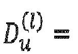
- the number delays


- In accordance with embodiments, the Doppler-frequency components are configured as follows:
- the

- the

- the

- the

- the number of Doppler-frequency components

- the number of Doppler-frequency components

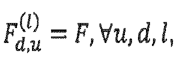
- the number of Doppler frequency-components


- the number of Doppler frequency-vectors


- the number of Doppler frequency-components


- the number of Doppler frequency-components

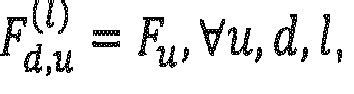
- the number of Doppler-frequency-components


- the number of Doppler frequency-components


- In accordance with embodiments,
- the explicit CSI is represented by a three-dimensional channel tensor

- the explicit CSI is represented by a four-dimensional channel tensor
 representing the receive-side and transmit-side space components of the time-variant frequency-selective MIMO channel, respectively, and the third and fourth dimensions of
 representing the frequency and time component of the channel, respectively.
- In accordance with embodiments, the processor is configured to select a Doppler-delay precoder matrix ( W ) based on a performance metric for e.g., the mutual-information I( W ;), which is a function of the Doppler-delay precoder matrix W and a multi-dimensional channel tensor
 .
.
- In accordance with embodiments, the processor is configured to select a wideband CQI that optimizes the average block error rate
 for the T time instants.
- In accordance with embodiments, the processor is configured to
- use, in a first step, a high resolution parameter estimation algorithm to estimate parameters of a channel model directly from a multi-dimensional channel tensor , or to calculate the coefficients of H (t,w) directly in a non-parameterized form from the MIMO channel tensor
 ,
,
- use, in a second step, the parameterized channel model and the selected Doppler-delay-beam composite precoder W (l) (l = 1,..,L) to calculate a parameterized precoded time-variant MIMO channel model frequency-domain response as

- use, in a third step, the parameterized precoded MIMO channel model response to calculate one or more CQI values for one or more future time instants.
- In accordance with embodiments, the processor is configured to
- predict a CQI value for a time-instant/slot n + K, where n denotes the current time-instant/slot, and K denotes the relative time difference with respect to the current time-instant/slot n, and
- use the K predicted CQI values to calculate differential predicted CQI values by reducing the K predicted CQI values by the average CQI value.
- In accordance with embodiments, the communication device is configured to receive a CSI reporting configuration comprising a parameter CQI-PredictionTime assigned with the value K which is used by the communication device for CQI prediction.
- In accordance with embodiments, in case the CSI feedback uses the PMI, the processor is configured to report at least a two-component PMI,
- where the first PMI corresponds to the selected vectors


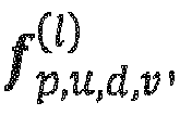
- where the second PMI corresponds to


- In accordance with embodiments, the processor is configured to
- represent the first-component PMI in the form of three-tuple sets, where each three-tuple (u,d,v) is associated with a selected spatial beam vector


- quantize the Doppler-delay-beam combining coefficients using a codebook approach, where the quantized Doppler-delay-beam combining coefficients are represented by i 2, the second PMI component, and
- report the two PMI components to the transmitter.
- In accordance with embodiments, for quantizing the complex Doppler-delay coefficients


-

-

- In accordance with embodiments, the CSI feedback further includes a rank indicator, RI, and wherein the processor is configured to report the RI for the transmission, wherein the RI is selected with respect to the Doppler-delay-beam precoder matrix W (l) (l = 1,..,L) and denotes an average number of layers supported by the Doppler-delay-beam precoded time-variant frequency-selective MIMO channel.
- In accordance with embodiments, the communication device is configured with a CSI-RS reporting configuration via a higher layer for reporting either the CQI and/or RI and/or PMI for a beam-formed CSI-RS, the vectors in the first codebook matrix represented by N 1 N 2-length column vectors, where the m-th vector (m = 1, ..., N 1 N 2) contains a single 1 at the m-th position and zeros elsewhere.
- In accordance with embodiments, the communication device is configured to receive a CSI-RS resource configuration including a higher layer (e.g., RRC) parameter, e.g., referred to as CSI-RS-BurstDuration, indicating a time-domain-repetition of the downlink reference signals, e.g., in terms of a number of consecutive slots the downlink reference signals are repeated in.
- In accordance with embodiments, the communication device assumes that for CQI, and/or RI, and/or PMI calculation, the transmitter applies the Doppler-delay-beam precoder to PDSCH signals on antenna ports {1000,1008 + v - 1} for v = L layers as

- [x(t,0)(i),...,x (t,v-1)(i)] T is a symbol vector of PDSCH symbols, P∈{1,2,4,8,12,16,24,32},
- x (t,u)(i) is the i-th symbol of layer u at time instant t,
- y (t,u)(i) is the precoded symbol transmitted on antenna port u at time instant t, and
- W (t,i) = [ W (1)(t,i), ..., W (L) (t,i)] is the predicted precoder matrix, with W (l)(t,i) being the t-th block and i-th column of W (l).
- The present invention provides a
transmitter 200 in a wireless communication system including acommunication device 202, the transmitter comprising: - an antenna array ANTT having a plurality of antennas for a wireless communication with one or more of the
inventive communication devices transmitter 200; - a
precoder 200b connected to the antenna array ANTT, theprecoder 200c to apply a set of beamforming weights to one or more antennas of the antenna array ANTT to form, by the antenna array ANTT, one or more transmit beams or one or more receive beams; - a
transceiver 200c configured to- transmit, to the
communication device - receive uplink signals comprising a plurality of CSI reports from the
communication device
processor 200a configured to- extract at least the two component precoder matrix identifier and the rank indicator from the plurality of CSI reports; and
- construct a Doppler-delay-beam precoder matrix applied on the antenna ports using a first component and a second component of the PMI, and determine the beamforming weights responsive to the constructed precoder matrix.
- transmit, to the
- In accordance with embodiments, to facilitate precoder matrix prediction for QT future time instants, the processor is configured to cyclically extend the Doppler-frequency DFT-vectors




the predicted precoder matrix for the l-th layer and q-th (q = 1,.., QT) time instant is given by


- The present invention provides a base wireless communication network, comprising at least one of the inventive UEs, and at least one of the inventive base stations.
- In accordance with embodiments, the communication device and the transmitter comprises one or more of: a mobile terminal, or stationary terminal, or cellular IoT-UE, or an IoT device, or a ground based vehicle, or an aerial vehicle, or a drone, or a moving base station, or road side unit, or a building, or a macro cell base station, or a small cell base station, or a road side unit, or a UE, or a remote radio head, or an AMF, or an SMF, or a core network entity, or a network slice as in the NR or 5G core context, or any transmission/reception point (TRP) enabling an item or a device to communicate using the wireless communication network, the item or device being provided with network connectivity to communicate using the wireless communication network.
- The present invention provides a method for providing a channel state information, CSI, feedback in a wireless communication system, the method comprising:
- receiving, from a transmitter, a radio signal via a time-variant, frequency-selective MIMO channel, the radio signal including downlink reference signals according to a reference signal configuration comprising a number of antenna ports, and downlink signals comprising the reference signal configuration;
- estimating, at the communication device, an explicit CSI in the frequency domain using measurements on the downlink reference signals on the radio channel, the downlink reference signals provided over a certain observation time,
- based on a performance metric, selecting, at the communication device, a Doppler-delay precoder matrix ( W ) for a composite Doppler-delay-beam three-stage precoder, the Doppler-delay-beam three-stage precoder being based on one or more codebooks, the one or more codebooks including
- ∘ one or more transmit-side spatial beam components of the composite Doppler-delay-beam three-stage precoder,
- ∘ one or more delay components of the composite Doppler-delay-beam three-stage precoder, and
- ∘ one or more Doppler-frequency components of the composite Doppler-delay-beam three-stage precoder,
- calculating, at the communication device, one or more of a channel quality indicator, CQI, a precoder matrix indicator, PMI, and a rank indicator, RI, using the explicit CSI and the composite Doppler-delay-beam three-stage precoder with the selected Doppler-delay-beam precoder matrix ( W ), and
- reporting from the communication device to the transmitter the CSI feedback including one or more of the CQI, the PMI and the RI, wherein the PMI and RI are used to indicate the Doppler-delay-beam three-stage composite precoder matrix for the configured antenna ports.
- The present invention provides a method for transmitting in a wireless communication system including a communication device and a transmitter, the method comprising:
- transmitting, to a communication device, downlink reference signals (CSI-RS) according to a CSI-RS configuration comprising a number of CSI-RS antenna ports and a parameter, e.g., referred to as CSI-RS BurstDuration, indicating a time-domain-repetition of the downlink reference signals, e.g., in terms of a number of consecutive slots the downlink reference signals are repeated in, and downlink signals comprising the CSI-RS configuration;
- receiving, at the transmitter, uplink signals comprising a plurality of CSI reports from the communication device;
- extracting, at the transmitter, at least the two component precoder matrix identifier and the rank indicator from the plurality of CSI reports;
- constructing, at the transmitter, a Doppler-delay-beam precoder matrix applied on the antenna ports using a first component and a second component of the PMI, and
- determining, responsive to the constructed precoder matrix, beamforming weights for a precoder connected to an the antenna array of the transmitter.
- The present invention provides a computer program product comprising instructions which, when the program is executed by a computer, causes the computer to carry out one or more methods in accordance with the present invention.
- Thus, embodiments of the present invention provides for an extension of the existing CSI-RS to track the channel time-evolution, e.g., for a channel having channel conditions which change fast, for example due to a high movement of the UE in a multi-path channel environment, and having a short channel coherence time. The present invention is advantageous as by tracking the channel time-evolution, even for channels with varying channel conditions, the CSI needs not to be updated less frequently, e.g., with a rate similar for channels with a long channel coherence time, thereby reducing or avoiding a feedback overhead. For example, the large-scale channel parameters such as path loss and shadow fading may not change quickly over time, even in a channel having a short channel coherence time, so that the channel variations are mainly related to small scale channel fading. This means the MIMO channel parameters of the impulse response such as path components and channel delays do not change over a longer time period, and channel variations caused by movement of the UE lead only to phase fluctuations of the MIMO channel path components. This means the spatial beams, the precoder Doppler-frequency DFT-vectors, the delay DFT-vectors as well as the Doppler-delay coefficients of the Doppler-delay-beam three-stage precoder remain identical or substantially identical for a long time period, and need to be less frequently updated.
- To address the above-mentioned issues in conventional approaches, according to which current CSI feedback schemes are not sufficient, embodiments of the present invention provide a CSI-RS design allowing track time-evolution of CSI or a new implicit CSI reporting scheme that takes into account the channel time-evolution and provides information about current and future RI, PMI and CQI in a compressed form to reduce the feedback rate.
-
Fig. 4 is a flow diagram illustrating the configuration of CSI parameters, the CSI measurement, the composite precoder matrix calculation and the CSI reporting in accordance with an embodiment of the present invention. The UE may be configured with a CSI-RS resource configuration via a higher layer (such as RRC) containing information about the number of assigned CSI-RS ports used for the transmission to the UE. The number of CSI-RS ports, M, is equal to PN 1 N 2 (where P =1 for co-polarized array antennas, and P =2 for dual-polarized array antennas at the base station), and where N 1 and N 2 are the number of antenna ports of the first and second spatial dimensions of the gNB array, respectively. The UE is configured with a CSI reporting configuration via a higher layer and/or a physical layer (via DCI) that also contains information for an evaluation of the CSI feedback parameters, such as CQI, RI and PMI, at the UE. The base station or gNB signals via a higher layer or a physical layer at least five integer values for (N 1 ,N 2 ,P), S, and T, where (N 1 ,N 2 ,P) are used to configure a first codebook, and S and T are used to configure a second codebook and a third codebook, respectively, for the PMI decomposition/calculation at the UE. The CQI, RI and PMI selection is performed at the UE according to the subsequently described embodiments. - At a
step 250, the gNB or base station sends a CSI-RS configuration and CSI report configuration to the UE. In accordance with embodiments, the CSI-RS configuration may include a CSI-RS resource(s) configuration with respect to sub-clause 7.4.1.5 in TS 38.211 [1] and with sub-clause 6.3.2 in TS.38.331 [4]. Further, an additional higher layer parameter configuration referred to as CSI-RS-BurstDuration is included. - The CSI-RS-BurstDuration is included to provide a CSI-RS design allowing to track the time-evolution of the channel. In accordance with embodiments, a UE is configured with a CSI-RS resource set(s) configuration with the higher layer parameter CSI-RS-BurstDuration, in addition to the configurations from clause 7.4.1.5 in TS 38.211 [2] and clause 6.3.2 in TS.38.331 [4] mentioned above, to track the time-evolution of CSI. The time-domain-repetition of the CSI-RS, in terms of the number of consecutive slots the CSI-RS is repeated in, is provided by the higher layer parameter CSI-RS-BurstDuration. The possible values of CSI-RS-BurstDuration for the NR numerology µ are 2 µ · XB slots, where XB ∈ {0,1,2, ...,maxNumBurstSlots - 1}. The NR numerology µ = 0,1,2,3,4 ... defines, e.g., a subcarrier spacing of 2 µ · 15kHz in accordance with the NR standard.
- For example, when the value of XB = 0 or the parameter CSI-RS-BurstDuration is not configured, there is no repetition of the CSI-RS over multiple slots. The burst duration scales with the numerology to keep up with the decrease in the slot sizes. Using the same logic used for periodicity of CSI-RS.
Fig. 5(a) illustrates a CSI-RS with a periodicity of 10 slots and no repetition (CSI-RS-BurstDuration not configured or CSI-RS-BurstDuration = 0), andFig. 5(b) illustrates a CSI-RS with a periodicity of 10 slots and repetition of 4 slots (CSI-RS-BurstDuration = 4).Fig. 6 illustrates a CSI-RS-BurstDuration information element in accordance with an embodiment. The information element of the new RRC parameter CSI-RS-BurstDuration is as follows: the value next to the text burstSlots indicates the value of XB, which for a given New Radio numerology µ (see [1]) provides theburst duration 2 µ · XB of the CSI-RS, i.e., the number of consecutive slots of CSI-RS repetition. - The burst-CSI-RS across multiple consecutive slots enables the extraction of time-evolution information of the CSI and for reporting of the precoder matrix, e.g. as a part of the PMI, in a way as described in more detail below. In other words, the UE may calculate the CQI, RI and PMI according to the embodiments described below with a repetition of the CSI-RS resource(s) over multiple consecutive slots, and report them accordingly.
- Returning to the flow diagram of
Fig. 4 , the CSI report configuration provided by the eNB may further include one or more of at least the following parameters: - ∘ a configuration of the CSI report configuration with respect to sub-clause 5.2.1.1 in TS 38.214 [2], and the following higher layer parameters: ReportQuantity listed in TS 38.331 [1] with the following additional parameters:
- ▪ cri-RI-PMIDD-CQI
- ▪ cri-RI-PMIDy-CQI
- ▪ cri-RI-PMIDr-CQI
- ▪ cri-RI-LI-PMIDD-CQI
- ▪ cri-RI-LI-PMIDy-CQI
- ▪ cri-RI-LI-PMIDr-CQI
- ▪ cri-RI-PMIDD
- ▪ cri-RI-PMIDy
- ▪ cri-RI-PMIDr
- ▪ PMIDD - PMI values including the delay and the Doppler-frequency component configurations as described in the embodiments below;
- ▪ PMIDy - PMI values including only the delay component configuration as described in the embodiments below, excluding the Doppler-frequency component(s);
- ▪ PMIDr - PMI values including only the Doppler-frequency component configuration as described in the embodiments below, excluding the delay component(s).
- ∘ a parameter CQI-PredictionTime assigned with the value K for CQI prediction (if configured).
- The CQI value, predicted CQI value, etc. (if configured) as mentioned in the reporting quantity may be calculated as explained in subsequently described embodiments over multiple time slots. The values of the CQI reported are identical as mentioned in TS 38.214 [2].
- In addition, the following parameters may be signaled by the eNB to the user equipment via physical layer or higher layer (RRC) parameters:
- ∘ values of S and T for the configuration of the delay and Doppler-frequency component codebooks Ω2 and Ω3, respectively, are represented by the parameters CodebookConfig-S, CodebookConfig-T. The oversampling factors O 2 and O 3 of the codebooks Ω2 and Ω3 are represented by CodebookConfig-O2 and CodebookConfig-O3, respectively.
- ∘ parameters N 1, N 2 and oversampling factors O 1,1 and O 1,2 for the configuration of the first codebook Ω1, as described below. The parameters N 1 and N 2 are represented by CodebookConfig-N1 and CodebookConfig-N2, respectively. The oversampling factors O 1,1 and O 1,2 are represented by CodebookConfig-O1_1 and CodebookConfig-O1_2, respectively.
- In response to the report configuration, the UE
- performs, at
step 252, measurements on downlink CSI-RS over T consecutive time-instants/slots, - constructs, at
step 254, the time-variant frequency-selective MIMO channel tensor;
- selects, at
step 256, the Doppler-delay-beam composite three-stage precoder matrix for each layer (PMI selection) with respect to a specific performance metric as explained in more detail below; - calculates, at
step 258, a CQI value, a predicted CQI value, or predicted differential CQI values (if configured) for a future time instant or for a set of future time instants using the selected Doppler-delay-beam composite three-stage precoder matrix and at least one of the MIMO channel tensorand a prediction of the MIMO channel tensor for future time instants, and, optionally, selects a RI value (if configured) using the selected Doppler-delay-beam composite three-stage precoder matrix and the MIMO channel tensor , and
, and
- sends, at
step 260, the CSI report to the gNB. - The gNB, at
step 262, reconstructs the Doppler-delay-beam composite three-stage precoder matrix (PMI report) to facilitate multi-user precoding matrix calculation and precoder matrix prediction for future time instants. - Other embodiments of the inventive approach operating on the basis of repeated downlink reference signals may use other precoders or other techniques to determine the CSI feedback based on the repeated downlink reference signals and to report determine the CSI feedback.
- In accordance with embodiments, once the UE is configured with a CSI-RS resource and a CSI reporting configuration (see
step 250 inFig. 4 ), the UE estimates an un-quantized explicit CSI using measurements on the downlink CSI-RS on PRBs, where the CSI-RS is configured over T consecutive time instants/slots in the frequency domain (seestep 252 inFig. 4 ). - In accordance with embodiments, the explicit CSI is represented by a three-dimensional channel tensor (a three-dimensional array)

Fig. 7 ), and N = Nr · N 1 · N 2 · P, where Nr is the number of UE receive antennas. Here, the first, second and third dimension of the channel tensor represent the space, frequency, and time component of the time-variant frequency-selective MIMO channel, respectively. - In accordance with other embodiments, the explicit CSI is represented by a four-dimensional channel tensor
 represent the receive-side and transmit-side space components of the time-variant frequency-selective MIMO channel, respectively. The third and fourth dimension of
 represent the frequency and time component of the MIMO channel, respectively.
- In a next step, the UE calculates a CQI using the explicit CSI in the form of the channel tensorand a composite Doppler-delay-beam three-stage precoder constructed using three separate codebooks:

- a first codebook Ω 1 for the transmit-side space (beams) components of the Doppler-delay-beam precoder;
- a second codebook Ω 2 for the delay components of the Doppler-delay-beam precoder; and
- a third codebook Ω 3 for the Doppler-frequency components of the Doppler-delay-beam precoder.
- In accordance with embodiments, instead of using three separate codebooks, the above mentioned beam, delay and Doppler-frequency components may be included into a single or common codebook, or two of the above mentioned beam, delay and Doppler-frequency components are included in one codebook, and the remaining component is included in another codebook.
- Assuming a rank-L transmission, the composite Doppler-delay-beam three-stage precoder W (l) of dimension Nt · T × S for the l-th layer (l = 1,..,L) is represented by a (column-wise) Kronecker-product (assuming a dual-polarized transmit antenna array at the gNB) as
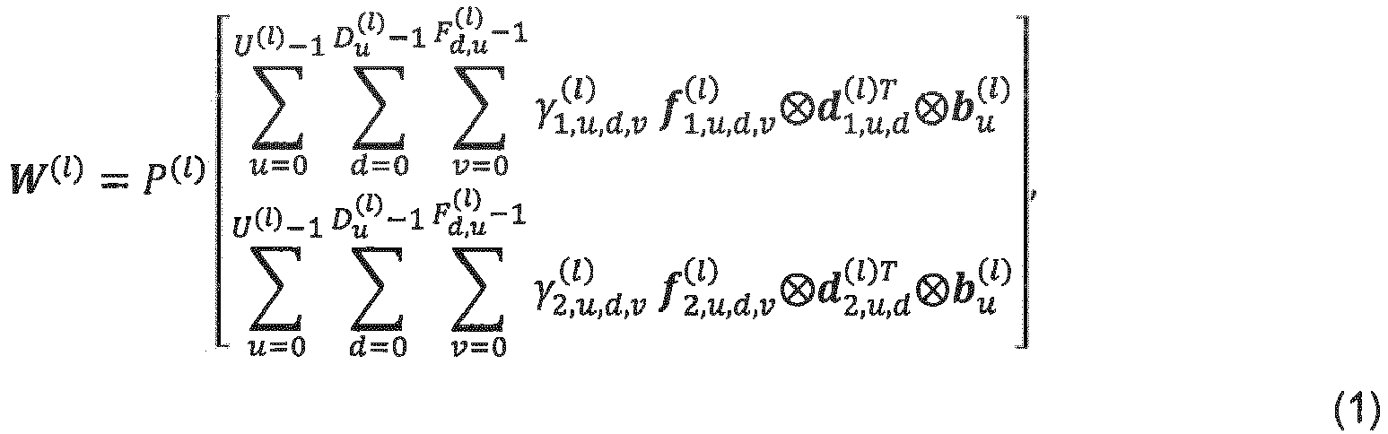
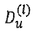

-

-

-

-

- P(l) is a scalar normalization factor to ensure that the average total transmission power over all precoder layers is 1.
- A structure of the Doppler-delay-beam composite precoder matrix is shown in
Fig. 8 , which illustrates the composite Doppler-delay-beam precoder matrix of size Nt · T × S. - In accordance with other embodiments, the Doppler-delay-beam precoder may be expressed as a dual-stage precoder:


- In accordance with embodiments, the values for the number of beams, delays, and Doppler-frequency components


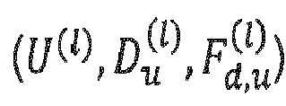
- In accordance with embodiments, the number of beams U (l) may be configured to be non-identical over the layers. In accordance with other embodiments, the number of beams U (l) may be configured to be identical for all layers. In this case, U (l) = U, ∀l. In accordance with other embodiments, the beam configuration may be a-priori known by the UE.
- In accordance with various embodiments, the delay components are configured in different ways, as will now be described.
- In accordance with a first embodiment, the

- In accordance with a second embodiment, the

- In accordance with a third embodiment, the

- In accordance with a fourth embodiment, the

- In accordance with a fifth embodiment, the

- In accordance with a sixth embodiment, the

- In accordance with a seventh embodiment, the number of delays

- In accordance with an eighth embodiment, the number of delays

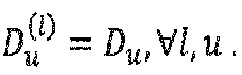
- In accordance with a ninth embodiment, the number of delays


- In accordance with a tenth embodiment, the number delays


- The delay components configuration as explained above may be configured via a higher layer (e.g., RRC, or MAC) signaling or may be configured as a part of DCI (physical layer signaling) in the downlink grant from the gNB to the UE. In accordance with other embodiments, the delay configuration may be a-priori known by the UE.
- In accordance with various embodiments, the Doppler-frequency components are configured in different ways, as will now be described.
- In accordance with a first embodiment, the number of Doppler-frequency components

- In accordance with a second embodiment, the number of Doppler-frequency components


- In accordance with a third embodiment, the number of Doppler frequency-components
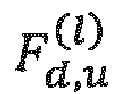

- In accordance with a fourth embodiment, the number of Doppler frequency-vectors


- In accordance with a fifth embodiment, the number of Doppler frequency-components


- In accordance with a sixth embodiment, the number of Doppler frequency-components


- In accordance with a seventh embodiment, the number of Doppler-frequency-components


- In accordance with an eighth embodiment, the number of Doppler frequency-components


- In accordance with a ninth embodiment, the

- In accordance with a tenth embodiment, the

- In accordance with an eleventh embodiment, the

- In accordance with a twelfth embodiment, the

- The Doppler-frequency components configuration as explained above may be configured via a higher layer (e.g., RRC, or MAC) signaling or may be configured as a part of DCI (physical layer signaling) in the downlink grant from the gNB to the UE. In accordance with other embodiments, the Doppler-frequency configuration may be a-priori known by the UE.
- Embodiments for implementing the above mentioned codebooks are now described.
- In accordance with embodiments, the vectors (spatial beams)


- The delay vectors

2 -1] of size S × SO 2. The DFT-codebook matrix Ω 2 contains SO 2 vectors, where each vector is represented by a length-S DFT-vector
- The Doppler-frequency vectors

3 -1] of size T × TO 3 . The DFT-codebook matrix Ω 3 contains TO 3 vectors, where each vector is represented by a length-T DFT-vector a l =
- The oversampled factors O 1,1, O 1,2, O 2, O 3 of the DFT-codebook matrices may be configured via a higher layer (e.g., RRC, or MAC) signaling or may be configured as a part of the DCI (physical layer signaling) in the downlink grant from the gNB to the UE. Alternatively, the oversampled factors O 1,1, O 1,2, O 2, O 3 of the DFT-codebook matrices may be known by the UE.
- The UE selects a preferred Doppler-delay precoder matrix W based on a performance metric (see
step 256 inFig. 4 ). - In accordance with embodiments, the UE selects the precoder matrix W that optimizes the mutual-information I( W ;), which is a function of the Doppler-delay precoder matrix W and the multi-dimensional channel tensor
 , for each configured SB, PRB, or subcarrier.
- In accordance with other embodiments, the U spatial beams, Doppler frequencies and delays are selected step-wise. For example, for a rank-1 transmission, in a first step, the UE selects the U spatial beams that optimize the mutual information:

- In a second step, the UE calculates the beam-formed channel tensorof dimension 2UNr × S × T with the U spatial beams


- In a third step, the UE selects three-tuples of Doppler-frequency DFT-vectors, delay DFT-vectors and Doppler-delay-beam combining coefficients, where the Doppler-frequency and delay DFT-vectors are selected from the codebooks Ω 3 and Ω 2, respectively, such that the mutual information

- In accordance with embodiments, the UE may select the rank indicator, RI, for reporting (see
step 258 inFig. 4 ). When RI reporting is configured at the UE, the UE reports a rank indicator (total number of layers) for the transmission. The rank indicator is selected with respect to the Doppler-delay-beam precoder matrix W (l) (l = 1,..,L) (see equation (1) above), and denotes the average number of layers supported by the Doppler-delay-beam precoded time-variant frequency-selective MIMO channel. - In accordance with embodiments, the UE may select the channel quality indicator, CQI, for reporting (see
step 258 inFig. 4 ). When CQI reporting is configured at the UE, the UE reports a preferred CQI based on a specific performance metric such as signal-to-interference and noise ratio (SINR), average bit error rate, average throughput, etc. - For example, the UE may select the CQI that optimizes the average block error rate block_error_rate(| W (l) (l = 1,..,L)) at the UE for the selected composite Doppler-delay-beam precoder matrix W (l) (l = 1,..,L) (see equation (1) above) and a given multi-dimensional channel tensor
 for the for the T time instants. The CQI value represents an "average" CQI supported by the Doppler-delay-beam precoded time-variant frequency-selective MIMO channel.
- Moreover, in accordance with other embodiment, a CQI (multiple CQI reporting) for each configured SB may be reported using the selected composite Doppler-delay-beam precoder matrix W (l) (l = 1,..,L) (see equation (1) above) and a given multi-dimensional channel tensorfor the T time instances.

- In accordance with embodiments, the UE may select the precoder matrix indicator, PMI, for reporting (see
step 258 inFig. 4 ). When PMI reporting is configured at the UE, the UE reports at least a two-component PMI. - The first PMI component may correspond to the selected vectors

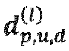


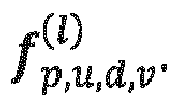


Fig 9 illustrates feedback indices associated with a beam, delay and Doppler-frequency components for a layer-1 transmission assuming equal number of delays per beam
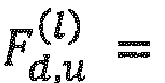
-
Fig 9 illustrates feedback indices associated with a beam, delay and Doppler-frequency components for a layer-1 transmission assuming equal number of delays per beam

Fig. 9 shows an example for i 1 for a layer-1 transmission. The subset i 1,1 of i 1 represents the beam indices selected from the codebook Ω 1 and are denoted by au , ∀u. The subset i 1,2 of i 1 represents the delay indices selected from the codebook Ω 2 and are denoted by cd,u, ∀d, u. The subset i 1,3 of i 1 represents the selected Doppler-frequency indices from the codebook Ω 3 and are denoted by ev,d,u, ∀v,d,u. - In accordance with embodiments, to report the


- The large-scale channel parameters such as path loss and shadow fading do not change quickly over time, and the channel variations are mainly related to small scale channel fading. This means the MIMO channel parameters of the impulse response such as path components and channel delays do not change over a longer time period, and channel variations caused by movement of the UE lead only to phase fluctuations of the MIMO channel path components. This means the spatial beams, the precoder Doppler-frequency DFT-vectors, the delay DFT-vectors as well as the Doppler-delay coefficients of the Doppler-delay-beam three-stage precoder W (l) remain identical for a long time period, and need to be less frequently updated.
- In accordance with embodiments, the gNB may use the two-component PMI feedback from the UE to construct the precoder matrix according to the codebook-based construction shown in
Fig. 10 , which illustrates a codebook based construction of the l-th layer precoder at the gNB and the association of the l-th layer precoder with the antenna ports (AP) for an example configuration N 1 = 4, N 2 = 2, P = 2. The precoder matrix information is used to calculate a multi-user precoding matrix which is applied to the transmission signals to adapt the transmission parameters to the current multiuser channel conditions. The above Doppler-delay composite Kronecker-based precoder matrix definition also facilitates the prediction of precoder matrices for future time instances. In this way, the number of CSI reports may be drastically reduced and feedback overhead is saved. - To facilitate precoder matrix prediction for QT future time instants, the Doppler-frequency DFT-vectors


- The predicted precoding matrices may be used in predictive multi-user scheduling algorithms that attempt to optimize, for example, the throughput for all users by using the knowledge of current and future precoder matrices of the users.
- In accordance with embodiments the UE may be configured to quantize the complex Doppler-delay coefficients


-

-

- In accordance with other embodiments, each coefficient may be represented by its real and imaginary part as

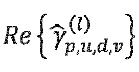

- In accordance with further embodiments the UE may be configured to predict a CQI value for time-instant/slot "n + K", where n denotes the current time-instant/slot, and K denotes the relative time difference with respect to the current time-instant/slot n.
- In one embodiment, the UE uses in a first step a high resolution parameter estimation algorithm, such as RIMAX (see reference [5]), to estimate parameters of a channel model directly from the multi-dimensional channel tensor. For example, the time-variant MIMO channel model impulse response may be defined by a number of channel taps, where each channel tap is parameterized with a channel gain, Doppler-frequency shift and a delay. The time-variant frequency-selective MIMO channel model frequency-domain response between the i-th gNB antenna and the j-th UE antenna may be expressed by


- M is the number of channel delays,
- hi,j (m) is the m-th path gain with associated Doppler-frequency shift f m and channel delay τ m,
- t represent the time instant,
- w denotes the subcarrier index, and
- W denotes the total number of subcarriers.
- In the present example, a non-polarimetric channel model is assumed, where the channel delays are identical for all links (i,j) of the MIMO channel.
- It is noted that the coefficients of H (t,w) may also be calculated directly in a non-parameterized form from the MIMO channel tensorby using a linear block-filtering approach such as least squares or minimum-mean-squared-error (MMSE) filtering (see references [6] and [7]). In this case, the channel predictor is formed by a weighted sum of the MIMO channel tensor
 .
.
- In a second step, the parameterized channel model and the selected Doppler-delay-beam composite precoder W (l) (l = 1,..,L) (see equation (1) above) are used to calculate a parameterized precoded time-variant MIMO channel model frequency-domain response as

Fig. 8 ). - In a third step, the UE uses the parameterized precoded MIMO channel model response to calculate a CQI value for a future time instant n + K, i.e., the CQI(n + K) is expressed as a function of H prec (n + K, w).
- In accordance with further embodiments, the UE may use the above parameterized precoded MIMO channel response also to predict K future CQI values (multiple CQI reporting) for the "n + k" (k = 0,.., K) future time instants. The K predicted CQI values may be used to calculate differential predicted CQI values by reducing the K predicted CQI values by the "average" CQI value. The predicted single CQI value, or predicted K CQI values, or predicted K differential CQI values is/are reported to the gNB.
- As mentioned above, other embodiments operating on the basis of repeated downlink reference signals may use other precoders or other techniques to determine the CSI feedback based on the repeated downlink reference signals and to report determine the CSI feedback. Thus, further embodiments of the present invention provide a communication device for providing a channel state information, CSI, feedback in a wireless communication system, wherein the communication device receives a CSI-RS resource configuration including a higher layer (e.g., RRC) parameter, e.g., referred to as CSI-RS-BurstDuration, indicating a time-domain-repetition of the downlink reference signals, e.g., in terms of a number of consecutive slots the downlink reference signals are repeated in. The communication device determines the CSI feedback based on the repeated downlink reference signals and reports the determined CSI feedback.
- In accordance with embodiments the UE may be configured with a CSI-RS reporting configuration via a higher layer for reporting a CQI, RI and PMI (if configured) for beam-formed CSI-RS. In this case, the vectors in the first codebook matrix are represented by N 1 N 2-length column vectors, where the m-th vector (m = 1,...,N 1 N 2) contains a single 1 at the m-th position and zeros elsewhere.
- In accordance with embodiments the UE may assume that, for CQI, and/or RI, and/or PMI calculation, the gNB applies the Doppler-delay-beam precoder calculated with respect to equation (1) above, to the PDSCH signals on antenna ports {1000,1008 + v - 1} for v = L layers as

- [x(t,0)(i),...,x (t,v-1)(i)] T is a symbol vector of PDSCH symbols from the layer mapping defined in Subclause 7.3.1.4 of TS 38.211 [1], P ∈ {1,2,4,8,12,16,24,32},
- x (t,u)(i) is the i-th symbol of layer u at time instant t,
- y (t,u)(i) is the precoded symbol transmitted on antenna port u at time instant t, and
- W (t,i) = [ W (1)(t,i),...,W (L)(t,i)] is the predicted precoder matrix calculated according to equation (1) with W (l)(t,i) being the t-th block and i-th column of W (l).
- The corresponding PDSCH signals [y (t,3000)(i) ··· y (t,3000+P-1)(i)] transmitted on antenna ports [3000,3000 + P - 1] have a ratio of, energy per resource element, EPRE, to CSI-RS EPRE equal to the ratio given in Subclause 4.1 of TS 38.214 [2].
- It is noted that for the current PDSCH transmission scheme as described in [2] the precoder matrix is kept constant over time until it is updated by a reported PMI. In contrast, the approach in accordance with embodiments takes into account the channel variations by updating the precoder matrix continuously over time without instantaneous PMI reporting.
- In accordance with embodiments, the wireless communication system may include a terrestrial network, or a non-terrestrial network, or networks or segments of networks using as a receiver an airborne vehicle or a spaceborne vehicle, or a combination thereof.
- In accordance with embodiments, the UE may comprise one or more of a mobile or stationary terminal, an loT device, a ground based vehicle, an aerial vehicle, a drone, a building, or any other item or device provided with network connectivity enabling the item/device to communicate using the wireless communication system, like a sensor or actuator.
- In accordance with embodiments, the base station may comprise one or more of a macro cell base station, or a small cell base station, or a spaceborne vehicle, like a satellite or a space, or an airborne vehicle, like a unmanned aircraft system (UAS), e.g., a tethered UAS, a lighter than air UAS (LTA), a heavier than air UAS (HTA) and a high altitude UAS platforms (HAPs), or any transmission/reception point (TRP) enabling an item or a device provided with network connectivity to communicate using the wireless communication system.
- The embodiments of the present invention have been described above with reference to a communication system employing a
rank 1 orlayer 1 communication. However, the present invention is not limited to such embodiments and may also be implemented in a communication system employing a higher rank or layer communication. In such embodiments, the feedback includes the delays per layer and the complex precoder coefficients per layer. - The embodiments of the present invention have been described above with reference to a communication system in which the transmitter is a base station serving a user equipment, and the communication device or receiver is the user equipment served by the base station. However, the present invention is not limited to such embodiments and may also be implemented in a communication system in which the transmitter is a user equipment station, and the communication device or receiver is the base station serving the user equipment. In accordance with other embodiments, the communication device and the transmitter may both be UEs communicating via directly, e.g., via a sidelink interface.
- Although some aspects of the described concept have been described in the context of an apparatus, it is clear that these aspects also represent a description of the corresponding method, where a block or a device corresponds to a method step or a feature of a method step. Analogously, aspects described in the context of a method step also represent a description of a corresponding block or item or feature of a corresponding apparatus.
- Various elements and features of the present invention may be implemented in hardware using analog and/or digital circuits, in software, through the execution of instructions by one or more general purpose or special-purpose processors, or as a combination of hardware and software. For example, embodiments of the present invention may be implemented in the environment of a computer system or another processing system.
Fig. 11 illustrates an example of a computer system 350. The units or modules as well as the steps of the methods performed by these units may execute on one or more computer systems 350. The computer system 350 includes one or more processors 352, like a special purpose or a general purpose digital signal processor. The processor 352 is connected to a communication infrastructure 354, like a bus or a network. The computer system 350 includes a main memory 356, e.g., a random access memory (RAM), and a secondary memory 358, e.g., a hard disk drive and/or a removable storage drive. The secondary memory 358 may allow computer programs or other instructions to be loaded into the computer system 350. The computer system 350 may further include a communications interface 360 to allow software and data to be transferred between computer system 350 and external devices. The communication may be in the from electronic, electromagnetic, optical, or other signals capable of being handled by a communications interface. The communication may use a wire or a cable, fiber optics, a phone line, a cellular phone link, an RF link and other communications channels 362. - The terms "computer program medium" and "computer readable medium" are used to generally refer to tangible storage media such as removable storage units or a hard disk installed in a hard disk drive. These computer program products are means for providing software to the computer system 350. The computer programs, also referred to as computer control logic, are stored in main memory 356 and/or secondary memory 358. Computer programs may also be received via the communications interface 360. The computer program, when executed, enables the computer system 350 to implement the present invention. In particular, the computer program, when executed, enables processor 352 to implement the processes of the present invention, such as any of the methods described herein. Accordingly, such a computer program may represent a controller of the computer system 350. Where the disclosure is implemented using software, the software may be stored in a computer program product and loaded into computer system 350 using a removable storage drive, an interface, like communications interface 360.
- The implementation in hardware or in software may be performed using a digital storage medium, for example cloud storage, a floppy disk, a DVD, a Blue-Ray, a CD, a ROM, a PROM, an EPROM, an EEPROM or a FLASH memory, having electronically readable control signals stored thereon, which cooperate (or are capable of cooperating) with a programmable computer system such that the respective method is performed. Therefore, the digital storage medium may be computer readable.
- Some embodiments according to the invention comprise a data carrier having electronically readable control signals, which are capable of cooperating with a programmable computer system, such that one of the methods described herein is performed.
- Generally, embodiments of the present invention may be implemented as a computer program product with a program code, the program code being operative for performing one of the methods when the computer program product runs on a computer. The program code may for example be stored on a machine readable carrier.
- Other embodiments comprise the computer program for performing one of the methods described herein, stored on a machine readable carrier. In other words, an embodiment of the inventive method is, therefore, a computer program having a program code for performing one of the methods described herein, when the computer program runs on a computer.
- A further embodiment of the inventive methods is, therefore, a data carrier (or a digital storage medium, or a computer-readable medium) comprising, recorded thereon, the computer program for performing one of the methods described herein. A further embodiment of the inventive method is, therefore, a data stream or a sequence of signals representing the computer program for performing one of the methods described herein. The data stream or the sequence of signals may for example be configured to be transferred via a data communication connection, for example via the Internet. A further embodiment comprises a processing means, for example a computer, or a programmable logic device, configured to or adapted to perform one of the methods described herein. A further embodiment comprises a computer having installed thereon the computer program for performing one of the methods described herein.
- In some embodiments, a programmable logic device (for example a field programmable gate array) may be used to perform some or all of the functionalities of the methods described herein. In some embodiments, a field programmable gate array may cooperate with a microprocessor in order to perform one of the methods described herein. Generally, the methods are preferably performed by any hardware apparatus.
- The above described embodiments are merely illustrative for the principles of the present invention. It is understood that modifications and variations of the arrangements and the details described herein are apparent to others skilled in the art. It is the intent, therefore, to be limited only by the scope of the impending patent claims and not by the specific details presented by way of description and explanation of the embodiments herein.
-
- [1] 3GPP TS 38.211 V15.1.0, "3rd Generation Partnership Project; Technical Specification Group Radio Access Network; NR; Physical channels and modulation (Release 15), March 2018.
- [2] 3GPP TS 38.214 V15.1.0, "3rd Generation Partnership Project; Technical Specification Group Radio Access Network; NR; Physical layer procedures for data (Release 15), March 2018.
- [3] K. Manolakis, S. Jaeckel, V. Jugnickel, and V. Braun, "Channel Prediction by Doppler-Delay Analysis and Benefits for Base Station Cooperation," in 77th IEEE Vehicular Technology Conference, Jun 2013.
- [4] 3GPP TS 38.331 V15.1.0, "3rd Generation Partnership Project; Technical Specification Group Radio Access Network; NR; Radio Resource Control (RRC); Protocol specification (Release 15), March 2018.
- [5] R. S. Thomä, M. Landmann, and A. Richter, "RIMAX-A maximum likelihood framework for parameter estimation in multidimensional channel sounding." Proceedings of the International Symposium on Antennas and Propagation (ISAP'04). 2004.
- [6] I. Barhumi, G. Leus, and M. Moonen, "Optimal training design for MIMO OFDM systems in mobile wireless channels," IEEE Trans. Signal Process, vol. 51, no. 6, pp. 1615-1624, Jun. 2003.
- [7] P. Hoeher, S. Kaiser, and P. Robertson, "Two-dimensional pilot-symbol-aided channel estimation by Wiener filtering," in Proc. IEEE ICASSP-97, Munich, Germany, Apr. 1997, pp. 1845-1848.


Claims (31)
- A communication device for providing a channel state information, CSI, feedback in a wireless communication system, the communication device comprising:a transceiver configured to receive, from a transmitter a radio signal via a time-variant, frequency-selective MIMO channel, the radio signal including downlink reference signals according to a reference signal configuration comprising a number of antenna ports, and downlink signals comprising the reference signal configuration; anda processor configured to- estimate an explicit CSI in the frequency domain using measurements on the downlink reference signals on the radio channel, the downlink reference signals provided over a certain observation time,- select, based on a performance metric, a Doppler-delay precoder matrix (W) for a composite Doppler-delay-beam three-stage precoder, the Doppler-delay-beam three-stage precoder being based on one or more codebooks, the one or more codebooks including∘ one or more transmit-side spatial beam components of the composite Doppler-delay-beam three-stage precoder,∘ one or more delay components of the composite Doppler-delay-beam three-stage precoder, and∘ one or more Doppler-frequency components of the composite Doppler-delay-beam three-stage precoder,- calculate either one or more of a channel quality indicator, CQI, and/or a precoder matrix indicator, PMI, and/or a rank indicator, RI, using the explicit CSI and the composite Doppler-delay-beam three-stage precoder with the selected Doppler-delay-beam precoder matrix ( W ), and- report to the transmitter the CSI feedback including either one or more of the CQI, and/or the PMI and/or the RI, wherein the PMI and RI are used to indicate the Doppler-delay-beam three-stage composite precoder matrix for the configured antenna ports.
- The communication device of claim 1, wherein the Doppler-delay-beam three-stage precoder is based on three separate codebooks, and wherein the three separate codebooks include- a first codebook (Ω 1) for the one or more transmit-side spatial beam components of the composite Doppler-delay-beam three-stage precoder,- a second codebook (Ω 2) for the one or more delay components of the composite Doppler-delay-beam three-stage precoder, and- a third codebook (Ω 3) for the one or more Doppler-frequency components of the composite Doppler-delay-beam three-stage precoder.
- The communication device of claim 1 or 2, wherein the Doppler-delay precoder matrix (W) is represented by
 - U (l) is the number of beams per polarization for the l-th layer,-
 -
-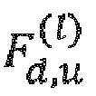 -
- -
- -
- -
- - P (l) is a scalar normalization factor to ensure that the average total transmission power over all precoder layers is 1.
 - The communication device of claim 1 or 2, wherein the Doppler-delay-beam precoder is represented by a dual-stage precoder:

where


 -
- -
- -
- -
- - P (l) is a scalar normalization factor to ensure that the average total transmission power over all precoder layers is 1.
 - The communication device of any one of the preceding claims, wherein- the first codebook (Ω 1) comprises a first oversampled DFT-codebook matrix of size N 1 N 2 × O 1,1 N 1 O 1,2 N 2 from which the vectors
 - wherein the second codebook (Ω 2) comprises a second oversampled DFT-codebook matrix of size S × SO 2 from which the delay vectors
 - wherein the third codebook (Ω 2) comprises a third oversampled DFT-codebook matrix of size T × TO 3 from which the Doppler-frequency vectors
- The communication device of any one of the preceding claims, wherein the communication device is configured to report to the transmitter the CSI feedback according to a CSI reporting configuration received from the transmitter, the CSI reporting configuration including, for example, the parameter ReportQuantity, which includes at least one the following values:- cri-RI-PMIDD-CQI,- cri-RI-PMIDy-CQI,- cri-RI-PMIDr-CQI,- cri-RI-LI-PMIDD-CQI,- cri-RI-LI-PMIDy-CQI,- cri-RI-LI-PMIDr-CQI,- cri-RI-PMIDD,- cri-RI-PMIDy,- cri-RI-PMIDr,wherein the PMI quantities are defined as:- PMIDD - PMI values including the delay and the Doppler-frequency component configurations,- PMIDy - PMI values including only the delay component configuration, excluding the Doppler-frequency component(s), and- PMIDr - PMI values including only the Doppler-frequency component configuration, excluding the delay component(s).
- The communication device of any one of the preceding claims, wherein the communication device is configured to receive the following values from the transmitter using Radio Resource Control (RRC) layer or physical layer (L1) parameters:- values of S and T for the configuration of the delay and Doppler-frequency component codebooks (Ω2, Ω3), and- parameters N 1, N 2 and oversampling factors O 1,1 and O 1,2 for the configuration of the first codebook (Ω1).
- The communication device of any one of the preceding claims, wherein the spatial beam components are configured as follows:- the number of beams U (l) is non-identical over the layers, or- the number of beams U (l) is identical for all layers such that U (l) = U, ∀l.
- The communication device of any one of the preceding claims, wherein the delay components are configured as follows:- the
 - the
- the - the
- the - the
- the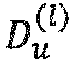 - the
- the - the
- the - the number of delays
 - the number of delays
 - the number of delays
 - the number delays

- The communication device of any one of the preceding claims, wherein the Doppler-frequency components are configured as follows:- the
 - the
- the - the
- the - the
- the - the number of Doppler-frequency components
 - the number of Doppler-frequency components
 - the number of Doppler frequency-components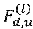
 - the number of Doppler frequency-vectors
 - the number of Doppler frequency-components
 - the number of Doppler frequency-components
 - the number of Doppler-frequency-components
 - the number of Doppler frequency-components

- The communication device of any one of the preceding claims, wherein- the explicit CSI is represented by a three-dimensional channel tensor
 - the explicit CSI is represented by a four-dimensional channel tensor
 representing the receive-side and transmit-side space components of the time-variant frequency-selective MIMO channel, respectively, and the third and fourth dimensions of
 representing the frequency and time component of the channel, respectively.
- The communication device of any one of the preceding claims, wherein the processor is configured to select a Doppler-delay precoder matrix ( W ) based on a performance metric for e.g., the mutual-information I( W ;), which is a function of the Doppler-delay precoder matrix W and a multi-dimensional channel tensor
 .
.
- The communication device of claim 12, wherein the processor is configured to select a wideband CQI that optimizes the average block error rate
 for the T time instants.
- The communication device of any one of claims 1 to 11, wherein the processor is configured to- use, in a first step, a high resolution parameter estimation algorithm to estimate parameters of a channel model directly from a multi-dimensional channel tensor, or to calculate the coefficients of H (t,w) directly in a non-parameterized form from the MIMO channel tensor
 ,
, - use, in a second step, the parameterized channel model and the selected Doppler-delay-beam composite precoder W (l) (l = 1,..,L) to calculate a parameterized precoded time-variant MIMO channel model frequency-domain response as
 - use, in a third step, the parameterized precoded MIMO channel model response to calculate one or more CQI values for one or more future time instants.
 - The communication device of any one of the preceding claims, wherein the processor is configured to- predict a CQI value for a time-instant/slot n + K, where n denotes the current time-instant/slot, and K denotes the relative time difference with respect to the current time-instant/slot n, and- use the K predicted CQI values to calculate differential predicted CQI values by reducing the K predicted CQI values by the average CQI value.
- The communication device of claim 15, wherein the communication device is configured to receive a CSI reporting configuration comprising a parameter CQI-PredictionTime assigned with the value K which is used by the communication device for CQI prediction.
- The communication device of any one of the preceding claims, wherein, in case the CSI feedback uses the PMI, the processor is configured to report at least a two-component PMI,- where the first PMI corresponds to the selected vectors


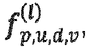 - where the second PMI corresponds to

- The communication device of claim 17, wherein the processor is configured to- represent the first-component PMI in the form of three-tuple sets, where each three-tuple (u,d,v) is associated with a selected spatial beam vector


 - quantize the Doppler-delay-beam combining coefficients using a codebook approach, where the quantized Doppler-delay-beam combining coefficients are represented by i 2, the second PMI component, and- report the two PMI components to the transmitter.
 - The communication device of claim 18, wherein, for quantizing the complex Doppler-delay coefficients

 -
- -wherein each coefficient is represented by its real and imaginary part as


- The communication device of any one of the preceding claims, wherein the CSI feedback further includes a rank indicator, RI, and
wherein the processor is configured to report the RI for the transmission, wherein the RI is selected with respect to the Doppler-delay-beam precoder matrix W (l) (l = 1,..,L) and denotes an average number of layers supported by the Doppler-delay-beam precoded time-variant frequency-selective MIMO channel. - The communication device of any one of the preceding claims, wherein the communication device is configured with a CSI-RS reporting configuration via a higher layer for reporting either the CQI and/or RI and/or PMI for a beam-formed CSI-RS, the vectors in the first codebook matrix represented by N 1 N 2-length column vectors, where the m-th vector (m = 1, ..., N 1 N 2) contains a single 1 at the m-th position and zeros elsewhere.
- The communication device of any one of the preceding claims, wherein the communication device is configured to receive a CSI-RS resource configuration including a higher layer (e.g., RRC) parameter, e.g., referred to as CSI-RS-BurstDuration, indicating a time-domain-repetition of the downlink reference signals, e.g., in terms of a number of consecutive slots the downlink reference signals are repeated in.
- The communication device of any one of the preceding claims, wherein the communication device assumes that for CQI, and/or RI, and/or PMI calculation, the transmitter applies the Doppler-delay-beam precoder to PDSCH signals on antenna ports {1000,1008 + v - 1} for v = L layers as

 x (t,u)(i) is the i-th symbol of layer u at time instant t,y (t,u)(i) is the precoded symbol transmitted on antenna port u at time instant t, andW (t, i) = [ W (1)(t, i), ..., W (L)(t, i)] is the predicted precoder matrix, with W (l)(t, i) being the t-th block and i-th column of W (l).
 - A communication device for providing a channel state information, CSI, feedback in a wireless communication system,
wherein the communication device is configured to receive a reference signal resource configuration, e.g., a CSI-RS resource configuration, including a parameter, like a higher layer (e.g., RRC) parameter, e.g., referred to as CSI-RS-BurstDuration, the parameter indicating a time-domain-repetition of the downlink reference signals, e.g., in terms of a number of consecutive slots the downlink reference signals are repeated in, and
wherein the communication device is configured to determine the CSI feedback based on the repeated downlink reference signals and to report the determined CSI feedback. - A transmitter in a wireless communication system including a communication device, the transmitter comprising:an antenna array having a plurality of antennas for a wireless communication with one or more communication devices of any one of the preceding claims for providing a channel state information, CSI, feedback to the transmitter; anda precoder connected to the antenna array, the precoder to apply a set of beamforming weights to one or more antennas of the antenna array to form, by the antenna array, one or more transmit beams or one or more receive beams,a transceiver configured to- transmit, to the communication device, downlink reference signals (CSI-RS) according to a CSI-RS configuration comprising a number of CSI-RS antenna ports and a parameter, e.g., referred to as CSI-RS BurstDuration, indicating a time-domain-repetition of the downlink reference signals, e.g., in terms of a number of consecutive slots the downlink reference signals are repeated in, and downlink signals comprising the CSI-RS configuration; and- receive uplink signals comprising a plurality of CSI reports from the communication device; anda processor configured to:- extract at least the two component precoder matrix identifier and the rank indicator from the plurality of CSI reports; and- construct a Doppler-delay-beam precoder matrix applied on the antenna ports using a first component and a second component of the PMI, and determine the beamforming weights responsive to the constructed precoder matrix.
- The transmitter of claim 25, wherein, to facilitate precoder matrix prediction for QT future time instants, the processor is configured to cyclically extend the Doppler-frequency DFT-vectors
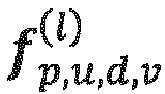
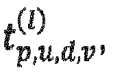


the predicted precoder matrix for the l-th layer and q-th (q = 1,..,QT) time instant is given by


- A wireless communication network, comprising:at least one communication device of any one of claims 1 to 24, andat least one BS of claim 25 or 26.
- The wireless communication network of claim 27, wherein the communication device and the transmitter comprises one or more of:- a mobile terminal, or- stationary terminal, or- cellular loT-UE, or- an loT device, or- a ground based vehicle, or- an aerial vehicle, or- a drone, or- a moving base station, or- road side unit, or- a building, or- a macro cell base station, or- a small cell base station, or- a road side unit, or- a UE, or- a remote radio head, or- an AMF, or- an SMF, or- a core network entity, or- a network slice as in the NR or 5G core context, or- any transmission/reception point (TRP) enabling an item or a device to communicate using the wireless communication network, the item or device being provided with network connectivity to communicate using the wireless communication network.
- A method for providing a channel state information, CSI, feedback in a wireless communication system, the method comprising:receiving, from a transmitter, a radio signal via a time-variant, frequency-selective MIMO channel, the radio signal including downlink reference signals according to a reference signal configuration comprising a number of antenna ports, and downlink signals comprising the reference signal configuration;estimating, at the communication device, an explicit CSI in the frequency domain using measurements on the downlink reference signals on the radio channel, the downlink reference signals provided over a certain observation time,based on a performance metric, selecting, at the communication device, a Doppler-delay precoder matrix ( W ) for a composite Doppler-delay-beam three-stage precoder, the Doppler-delay-beam three-stage precoder being based on one or more codebooks, the one or more codebooks including∘ one or more transmit-side spatial beam components of the composite Doppler-delay-beam three-stage precoder,∘ one or more delay components of the composite Doppler-delay-beam three-stage precoder, and∘ one or more Doppler-frequency components of the composite Doppler-delay-beam three-stage precoder,calculating, at the communication device, one or more of a channel quality indicator, CQI, a precoder matrix indicator, PMI, and a rank indicator, RI, using the explicit CSI and the composite Doppler-delay-beam three-stage precoder with the selected Doppler-delay-beam precoder matrix ( W ), andreporting from the communication device to the transmitter the CSI feedback including one or more of the CQI, the PMI and the RI, wherein the PMI and RI are used to indicate the Doppler-delay-beam three-stage composite precoder matrix for the configured antenna ports.
- A method for transmitting in a wireless communication system including a communication device and a transmitter, the method comprising:transmitting, to a communication device, downlink reference signals (CSI-RS) according to a CSI-RS configuration comprising a number of CSI-RS antenna ports and a parameter, e.g., referred to as CSI-RS BurstDuration, indicating a time-domain-repetition of the downlink reference signals, e.g., in terms of a number of consecutive slots the downlink reference signals are repeated in, and downlink signals comprising the CSI-RS configuration;receiving, at the transmitter, uplink signals comprising a plurality of CSI reports from the communication device;extracting, at the transmitter, at least the two component precoder matrix identifier and the rank indicator from the plurality of CSI reports;constructing, at the transmitter, a Doppler-delay-beam precoder matrix applied on the antenna ports using a first component and a second component of the PMI, anddetermining, responsive to the constructed precoder matrix, beamforming weights for a precoder connected to an the antenna array of the transmitter.
- A non-transitory computer program product comprising a computer readable medium storing instructions which, when executed on a computer, perform the method of claim 29 or 30.
Priority Applications (12)
| Application Number | Priority Date | Filing Date | Title |
|---|---|---|---|
| EP18175247.8A EP3576312A1 (en) | 2018-05-30 | 2018-05-30 | Doppler-delay codebook-based precoding and csi reporting for wireless communications systems |
| KR1020207037939A KR102539873B1 (en) | 2018-05-30 | 2019-05-29 | Doppler-delay codebook-based precoding and CSI reporting for wireless communication systems |
| ES19726446T ES2962518T3 (en) | 2018-05-30 | 2019-05-29 | Doppler delay codebook based precoding and csi reporting for wireless communications systems |
| JP2020567013A JP7246414B2 (en) | 2018-05-30 | 2019-05-29 | Doppler Delay Codebook Based Precoding and CSI Reporting for Wireless Communication Systems |
| PCT/EP2019/064024 WO2019229152A1 (en) | 2018-05-30 | 2019-05-29 | Doppler-delay codebook-based precoding and csi reporting for wireless communications systems |
| EP19726446.8A EP3804157B1 (en) | 2018-05-30 | 2019-05-29 | Doppler-delay codebook-based precoding and csi reporting for wireless communications systems |
| EP23180567.2A EP4250583A3 (en) | 2018-05-30 | 2019-05-29 | Doppler-delay codebook-based precoding and csi reporting for wireless communications systems |
| CN201980050859.4A CN112514276B (en) | 2018-05-30 | 2019-05-29 | Communication equipment and method for providing CSI feedback, transmitter and method and medium for transmitting |
| US17/098,592 US11616551B2 (en) | 2018-05-30 | 2020-11-16 | Doppler-delay codebook-based precoding and CSI reporting wireless communications systems |
| US18/171,777 US12047148B2 (en) | 2018-05-30 | 2023-02-21 | Doppler-delay codebook-based precoding and CSI reporting for wireless communications systems |
| US18/738,590 US12494827B2 (en) | 2018-05-30 | 2024-06-10 | Doppler-delay codebook-based precoding and CSI reporting for wireless communications systems |
| US19/354,015 US20260128769A1 (en) | 2018-05-30 | 2025-10-09 | Doppler-delay codebook-based precoding and csi reporting for wireless communications systems |
Applications Claiming Priority (1)
| Application Number | Priority Date | Filing Date | Title |
|---|---|---|---|
| EP18175247.8A EP3576312A1 (en) | 2018-05-30 | 2018-05-30 | Doppler-delay codebook-based precoding and csi reporting for wireless communications systems |
Publications (1)
| Publication Number | Publication Date |
|---|---|
| EP3576312A1 true EP3576312A1 (en) | 2019-12-04 |
Family
ID=62492538
Family Applications (3)
| Application Number | Title | Priority Date | Filing Date |
|---|---|---|---|
| EP18175247.8A Withdrawn EP3576312A1 (en) | 2018-05-30 | 2018-05-30 | Doppler-delay codebook-based precoding and csi reporting for wireless communications systems |
| EP19726446.8A Active EP3804157B1 (en) | 2018-05-30 | 2019-05-29 | Doppler-delay codebook-based precoding and csi reporting for wireless communications systems |
| EP23180567.2A Pending EP4250583A3 (en) | 2018-05-30 | 2019-05-29 | Doppler-delay codebook-based precoding and csi reporting for wireless communications systems |
Family Applications After (2)
| Application Number | Title | Priority Date | Filing Date |
|---|---|---|---|
| EP19726446.8A Active EP3804157B1 (en) | 2018-05-30 | 2019-05-29 | Doppler-delay codebook-based precoding and csi reporting for wireless communications systems |
| EP23180567.2A Pending EP4250583A3 (en) | 2018-05-30 | 2019-05-29 | Doppler-delay codebook-based precoding and csi reporting for wireless communications systems |
Country Status (7)
| Country | Link |
|---|---|
| US (4) | US11616551B2 (en) |
| EP (3) | EP3576312A1 (en) |
| JP (1) | JP7246414B2 (en) |
| KR (1) | KR102539873B1 (en) |
| CN (1) | CN112514276B (en) |
| ES (1) | ES2962518T3 (en) |
| WO (1) | WO2019229152A1 (en) |
Cited By (18)
| Publication number | Priority date | Publication date | Assignee | Title |
|---|---|---|---|---|
| WO2021128026A1 (en) * | 2019-12-24 | 2021-07-01 | 华为技术有限公司 | Information sending method, information receiving method and apparatus |
| EP3850761A1 (en) * | 2018-09-11 | 2021-07-21 | FRAUNHOFER-GESELLSCHAFT zur Förderung der angewandten Forschung e.V. | Doppler codebook-based precoding and csi reporting for wireless communications systems |
| WO2021160122A1 (en) * | 2020-02-10 | 2021-08-19 | 大唐移动通信设备有限公司 | Channel state information feedback method, device, terminal, and network side, and storage medium |
| CN113949401A (en) * | 2021-11-30 | 2022-01-18 | Oppo广东移动通信有限公司 | Radio frequency system and communication equipment |
| WO2022056503A1 (en) * | 2020-09-11 | 2022-03-17 | Qualcomm Incorporated | Observed environmental vector feedback for wireless communication |
| WO2022077463A1 (en) | 2020-10-16 | 2022-04-21 | Nokia Shanghai Bell Co., Ltd. | Indication of frequency domain components |
| CN114788198A (en) * | 2019-12-31 | 2022-07-22 | 华为技术有限公司 | Channel information feedback method and communication device |
| US20220329303A1 (en) * | 2021-03-25 | 2022-10-13 | Samsung Electronics Co., Ltd. | Method and apparatus for configuring csi reporting granularity |
| CN115413402A (en) * | 2020-03-06 | 2022-11-29 | 诺基亚技术有限公司 | Improved precoding |
| US20220386292A1 (en) * | 2021-06-01 | 2022-12-01 | Nokia Technologies Oy | Apparatus for CSI Prediction Control |
| US11563608B2 (en) | 2020-12-08 | 2023-01-24 | Electronics And Telecommunications Research Institute | Method and apparatus for signal modulation and demodulation in wireless communication system |
| CN115699962A (en) * | 2020-06-10 | 2023-02-03 | 联想(新加坡)私人有限公司 | Model-Based Predictive Disruption Management |
| CN116134747A (en) * | 2020-07-31 | 2023-05-16 | 高通股份有限公司 | Beam Measurement Report |
| EP4211956A4 (en) * | 2020-10-15 | 2023-11-15 | ZTE Corporation | CONFIGURATION OF CHANNEL STATUS INFORMATION REFERENCE SIGNALS FOR WIRELESS COMMUNICATION SYSTEMS |
| CN117643028A (en) * | 2022-06-30 | 2024-03-01 | 北京小米移动软件有限公司 | A channel state information feedback method and device thereof |
| US20240088970A1 (en) * | 2021-05-21 | 2024-03-14 | Vivo Mobile Communication Co., Ltd. | Method and apparatus for feeding back channel information of delay-doppler domain, and electronic device |
| US11991738B2 (en) * | 2017-04-21 | 2024-05-21 | Cohere Technologies, Inc. | Communication techniques using quasi-static properties of wireless channels |
| US12047148B2 (en) | 2018-05-30 | 2024-07-23 | Fraunhofer-Gesellschaft Zur Forderung Der Angewandten Förschung E.V. | Doppler-delay codebook-based precoding and CSI reporting for wireless communications systems |
Families Citing this family (62)
| Publication number | Priority date | Publication date | Assignee | Title |
|---|---|---|---|---|
| US11870524B2 (en) * | 2018-09-05 | 2024-01-09 | Lg Electronics Inc. | Method for reporting channel state information in order for performing antenna array-based beamforming in wireless communication system, and device therefor |
| WO2020172804A1 (en) * | 2019-02-26 | 2020-09-03 | Oppo广东移动通信有限公司 | Codebook feedback method, terminal device and network device |
| US10979151B2 (en) * | 2019-05-22 | 2021-04-13 | At&T Intellectual Property I, L.P. | Multidimensional grid sampling for radio frequency power feedback |
| US11824637B2 (en) | 2019-05-22 | 2023-11-21 | At&T Intellectual Property I, L.P. | Generating wireless reference signals in a different domain for transmission |
| US10886991B2 (en) * | 2019-05-22 | 2021-01-05 | At&T Intellectual Property I, L.P. | Facilitating sparsity adaptive feedback in the delay doppler domain in advanced networks |
| US11050530B2 (en) | 2019-06-27 | 2021-06-29 | At&T Intellectual Property I, L.P. | Generating wireless reference signals in a different domain for transmission with a collapsed time-frequency grid |
| US12088374B2 (en) * | 2019-08-21 | 2024-09-10 | Nippon Telegraph And Telephone Corporation | Wireless communication system, wireless communication method, transmitting station device and receiving station device |
| US11601169B2 (en) * | 2019-09-09 | 2023-03-07 | Samsung Electronics Co., Ltd. | Method and apparatus for port selection in wireless communication systems |
| CN112751592B (en) * | 2019-10-29 | 2021-11-19 | 华为技术有限公司 | Method and communication device for reporting channel state information |
| US11337095B2 (en) * | 2020-01-03 | 2022-05-17 | Qualcomm Incorporated | Forward-looking channel state information prediction and reporting |
| EP4128562A1 (en) * | 2020-04-03 | 2023-02-08 | Telefonaktiebolaget LM Ericsson (publ) | Pim downlink subspace acquisition method |
| US11483112B2 (en) | 2020-05-18 | 2022-10-25 | Qualcomm Incorporated | Uplink doppler metric estimation based on an uplink reference signal |
| US11310021B2 (en) * | 2020-05-18 | 2022-04-19 | Qualcomm Incorporated | Uplink doppler metric estimation based on a downlink reference signal |
| CN113810318B (en) * | 2020-06-17 | 2024-04-12 | 上海朗帛通信技术有限公司 | User equipment, method and device in base station for wireless communication |
| WO2022032424A1 (en) * | 2020-08-10 | 2022-02-17 | Qualcomm Incorporated | Procedures for port-selection codebook with frequency selective precoded reference signals |
| US12088378B2 (en) * | 2020-09-18 | 2024-09-10 | Qualcomm Incorporated | Low overhead and high accuracy channel state feedback using neural networks |
| US11483203B2 (en) | 2020-10-28 | 2022-10-25 | Charter Communications Operating, Llc | Methods and apparatus for enhancing scheduler fairness in small-cell wireless systems |
| US12273909B2 (en) | 2020-10-29 | 2025-04-08 | Charter Communications Operating, Llc | Methods and apparatus for data traffic prioritization in small-cell wireless systems |
| US11569931B2 (en) * | 2020-10-30 | 2023-01-31 | Charter Communications Operating, Llc | Methods and apparatus for enhancing wireless link throughput in small-cell wireless systems |
| US11576188B2 (en) * | 2020-12-17 | 2023-02-07 | T-Mobile Usa, Inc. | External interference radar |
| EP4277149A4 (en) * | 2021-02-03 | 2024-03-13 | Huawei Technologies Co., Ltd. | Precoding method and apparatus |
| CN115133965B (en) * | 2021-03-24 | 2023-09-15 | 维沃移动通信有限公司 | Information transmission methods and devices |
| EP4335040A4 (en) * | 2021-05-07 | 2025-01-22 | Apple Inc. | DOPPLER SHIFT ESTIMATION REPORT WITH PRE-COMPENSATION |
| US12267137B2 (en) * | 2021-05-11 | 2025-04-01 | Nokia Technologies Oy | Reporting channel state information (CSI) precoding matrix indicator (PMI) |
| WO2022246716A1 (en) * | 2021-05-27 | 2022-12-01 | Qualcomm Incorporated | Neural network assisted communication techniques |
| US11916633B2 (en) * | 2021-06-04 | 2024-02-27 | Qualcomm Incorporated | Non-codebook based precoding for sidelink communications |
| CN115442007A (en) * | 2021-06-04 | 2022-12-06 | 维沃移动通信有限公司 | A signal transmission method, device, equipment and system |
| CN115483950A (en) * | 2021-06-16 | 2022-12-16 | 华为技术有限公司 | Feedback method and device of channel state information |
| US12418817B2 (en) | 2021-06-18 | 2025-09-16 | Samsung Electronics Co., Ltd. | Method and apparatus for CSI reporting |
| US11665541B2 (en) * | 2021-06-23 | 2023-05-30 | EMC IP Holding Company LLC | 5G zero client monitor |
| CN115550987B (en) * | 2021-06-29 | 2025-11-07 | 北京紫光展锐通信技术有限公司 | Priority determining method and device for channel state information report and related equipment |
| US20240313919A1 (en) * | 2021-07-01 | 2024-09-19 | Lg Electronics Inc. | Method and device for transmitting and receiving channel state information on basis of codebook in wireless communication system |
| CN116076027B (en) * | 2021-09-03 | 2026-04-28 | 苹果公司 | Codebook design for high Doppler cases |
| US20250132800A1 (en) * | 2021-09-15 | 2025-04-24 | Mediatek Singapore Pte. Ltd. | Method and apparatus for mimo csi feedback |
| CN116095739A (en) * | 2021-10-29 | 2023-05-09 | 维沃移动通信有限公司 | Channel information reporting method, terminal and network side equipment |
| WO2023084421A1 (en) * | 2021-11-09 | 2023-05-19 | Telefonaktiebolaget Lm Ericsson (Publ) | Method and systems for csi reporting enhancement for type ii pmi prediction |
| US20230180153A1 (en) * | 2021-12-03 | 2023-06-08 | Qualcomm Incorporated | Adaptive doppler feedback |
| CN118575451A (en) * | 2021-12-28 | 2024-08-30 | 三星电子株式会社 | Method and apparatus for reporting Doppler information of time-varying channel in wireless communication system |
| JP2025500656A (en) * | 2022-01-11 | 2025-01-09 | 北京小米移動軟件有限公司 | Information reporting method, information receiving method, apparatus, device and storage medium |
| KR20240134867A (en) * | 2022-01-19 | 2024-09-10 | 엘지전자 주식회사 | Method and device for transmitting and receiving channel state information in a wireless communication system |
| CN114448758B (en) * | 2022-01-21 | 2024-07-16 | 华中科技大学 | Channel estimation method based on partial reciprocity in FDD massive MIMO systems |
| CN118648270A (en) * | 2022-02-07 | 2024-09-13 | 瑞典爱立信有限公司 | CSI-RS reception for high mobility |
| JP7856776B2 (en) * | 2022-02-17 | 2026-05-11 | クゥアルコム・インコーポレイテッド | System and method for utilizing Doppler frequency values for wireless communication |
| CN114786240B (en) * | 2022-03-02 | 2024-06-07 | 厦门大学 | 5G downlink signal intermittent tracking method |
| KR102731200B1 (en) * | 2022-03-11 | 2024-11-18 | 전북대학교산학협력단 | Method for time offset non-orthogonal multiple access in wireless communication multiple access area of next generation mobile communication system |
| US12580712B2 (en) * | 2022-03-30 | 2026-03-17 | Samsung Electronics Co., Ltd. | Method and apparatus for configuring semi-persistent CSI-RS resources |
| US20250096969A1 (en) * | 2022-04-01 | 2025-03-20 | Qualcomm Incorporated | Temporal domain precoding configuration for wireless communications |
| CN116961856A (en) * | 2022-04-25 | 2023-10-27 | 展讯通信(上海)有限公司 | A data processing method, chip and electronic device |
| WO2023206171A1 (en) * | 2022-04-27 | 2023-11-02 | 北京小米移动软件有限公司 | Csi reporting method and apparatus, precoding matrix determining method and apparatus, and device |
| US20250260454A1 (en) * | 2022-04-27 | 2025-08-14 | Beijing Xiaomi Mobile Software Co., Ltd. | Csi reporting method and apparatus, precoding matrix determination method and apparatus, and device |
| US20250274172A1 (en) * | 2022-04-28 | 2025-08-28 | Nec Corporation | Methods, devices, and computer readable medium for communication |
| CN119343894A (en) * | 2022-06-08 | 2025-01-21 | 苹果公司 | Methods and processes for AI-based CSI feedback with CSI prediction |
| US20230403060A1 (en) * | 2022-06-10 | 2023-12-14 | Samsung Electronics Co., Ltd. | Method and apparatus for csi reference resource and reporting window |
| CN115913833B (en) * | 2022-08-01 | 2025-08-15 | 华为技术有限公司 | Communication method and device |
| US20260045986A1 (en) * | 2022-08-01 | 2026-02-12 | Nec Corporation | Methods, devices, and medium for communication |
| CN115514436B (en) * | 2022-08-05 | 2023-04-14 | 郑州大学 | A channel prediction method for inter-satellite link for Massive MIMO LEO communication |
| US20240267766A1 (en) * | 2023-02-08 | 2024-08-08 | Qualcomm Incorporated | Techniques for channel quality information reporting |
| US20240323730A1 (en) * | 2023-03-22 | 2024-09-26 | Qualcomm Incorporated | Channel state feedback using sensing reference signals |
| EP4740312A1 (en) * | 2023-08-03 | 2026-05-13 | Google LLC | Beam combining codebook for low peak-to-average power ratio-based waveform |
| WO2025065639A1 (en) * | 2023-09-28 | 2025-04-03 | 富士通株式会社 | Indication method and apparatus for channel state information report configuration |
| WO2025147996A1 (en) * | 2024-01-12 | 2025-07-17 | Google Llc | Multiple channel state information feedback for multi-user multiple-input multiple-output pairing |
| US20250251488A1 (en) * | 2024-02-07 | 2025-08-07 | Samsung Electronics Company, Ltd. | Precoding Design for Integrated Sensing and Communication Systems |
Citations (1)
| Publication number | Priority date | Publication date | Assignee | Title |
|---|---|---|---|---|
| WO2018052255A1 (en) | 2016-09-14 | 2018-03-22 | Samsung Electronics Co., Ltd. | Method and apparatus to enable channel compression in advanced wireless communication systems |
Family Cites Families (42)
| Publication number | Priority date | Publication date | Assignee | Title |
|---|---|---|---|---|
| US7702029B2 (en) | 2006-10-02 | 2010-04-20 | Freescale Semiconductor, Inc. | MIMO precoding enabling spatial multiplexing, power allocation and adaptive modulation and coding |
| US20110250919A1 (en) * | 2010-04-13 | 2011-10-13 | Qualcomm Incorporated | Cqi estimation in a wireless communication network |
| KR102182322B1 (en) | 2012-07-31 | 2020-11-25 | 삼성전자주식회사 | Apparatus and method for communication based on beam-forming in wireless communication system |
| US8976884B2 (en) | 2012-12-20 | 2015-03-10 | Google Technology Holdings LLC | Method and apparatus for antenna array channel feedback |
| US8942302B2 (en) * | 2012-12-20 | 2015-01-27 | Google Technology Holdings LLC | Method and apparatus for antenna array channel feedback |
| WO2014168323A1 (en) | 2013-04-10 | 2014-10-16 | Lg Electronics Inc. | Layer alignment method and apparatus for multilayer three-dimensional beamforming in wireless communication system |
| US9853704B2 (en) | 2013-05-07 | 2017-12-26 | Lg Electronics Inc. | Method for reporting channel state information for three dimensional beamforming in wireless communication system and apparatus for same |
| KR102168637B1 (en) | 2013-12-03 | 2020-10-21 | 주식회사 아이티엘 | Method and apparatus of csi feedback in multiple antenna system |
| US10050756B2 (en) | 2014-04-09 | 2018-08-14 | Lg Electronics Inc. | Method for tranceiving signal in wireless communication system and apparatus therefor |
| EP3143704B1 (en) | 2014-05-15 | 2019-06-19 | LG Electronics Inc. | Method and apparatus for calculating feedback information for 3d mimo in wireless communication system |
| MX367251B (en) | 2014-08-07 | 2019-08-12 | Ericsson Telefon Ab L M | Aligning measurement gaps and discovery signals. |
| JP2016063497A (en) * | 2014-09-19 | 2016-04-25 | 日本電気株式会社 | Radio terminal device, control method thereof, and program |
| US9825742B2 (en) | 2014-10-03 | 2017-11-21 | Samsung Electronics Co., Ltd. | Codebook design and structure for advanced wireless communication systems |
| WO2016068628A1 (en) | 2014-10-31 | 2016-05-06 | Samsung Electronics Co., Ltd. | Codebook design and structure for advanced wireless communication systems |
| US10608761B2 (en) | 2014-12-16 | 2020-03-31 | Telefonaktiebolaget Lm Ericsson (Publ) | Methods and arrangements for CSI prediction |
| WO2016122387A1 (en) | 2015-01-29 | 2016-08-04 | Telefonaktiebolaget Lm Ericsson (Publ) | Channel state feedback for a wireless link having phase relaxed channels |
| CN107925466B (en) | 2015-07-23 | 2021-04-20 | Lg 电子株式会社 | Codebook-based signal transmission/reception method in multi-antenna wireless communication system |
| US10439691B2 (en) | 2015-07-23 | 2019-10-08 | Lg Electronics Inc. | Codebook-based signal transmission/reception method in multi-antenna wireless communication system, and device for same |
| CN108605238A (en) | 2016-02-04 | 2018-09-28 | 株式会社Ntt都科摩 | Base station, user equipment, power ratio application method, and channel state information transmission method |
| CN107181509A (en) | 2016-03-11 | 2017-09-19 | 电信科学技术研究院 | A kind of data transmission method and device |
| EP3422617A4 (en) | 2016-03-16 | 2019-03-06 | Huawei Technologies Co., Ltd. | SIGNAL TRANSMISSION PROCESS AND DEVICE |
| US10056956B2 (en) | 2016-03-24 | 2018-08-21 | Samsung Electronics Co., Ltd. | Precoder codebook for CSI reporting in advanced wireless communication systems |
| CN107438957B (en) | 2016-03-31 | 2021-05-28 | 瑞典爱立信有限公司 | Method and apparatus for indicating precoder parameters in a wireless communication network |
| CN110034797B (en) | 2016-04-01 | 2020-06-26 | 华为技术有限公司 | Precoding matrix indication feedback method and device |
| US10659118B2 (en) | 2016-04-19 | 2020-05-19 | Samsung Electronics Co., Ltd. | Method and apparatus for explicit CSI reporting in advanced wireless communication systems |
| WO2018045028A1 (en) * | 2016-08-31 | 2018-03-08 | Intel Corporation | Csi (channel state information)-rs (reference signal) techniques for channel estimation and beam refinement |
| JP2020500449A (en) * | 2016-09-30 | 2020-01-09 | テレフオンアクチーボラゲット エルエム エリクソン(パブル) | Wireless device, network node, and method performed therein |
| US10440693B2 (en) | 2016-11-04 | 2019-10-08 | At&T Intellectual Property I, L.P. | Asynchronous multi-point transmission schemes |
| US10721038B2 (en) * | 2016-11-22 | 2020-07-21 | Samsung Electronics Co., Ltd. | Method and apparatus for channel estimation and data decoding in wireless communication system |
| KR102364258B1 (en) | 2017-03-23 | 2022-02-17 | 엘지전자 주식회사 | Method for transmitting and receiving channel state information in a wireless communication system and apparatus therefor |
| JP6423475B2 (en) * | 2017-03-30 | 2018-11-14 | 華為技術有限公司Huawei Technologies Co.,Ltd. | Method and apparatus for determining a precoding matrix indicator, user equipment, and base station |
| CN109152054A (en) | 2017-06-16 | 2019-01-04 | 华硕电脑股份有限公司 | Method and apparatus for beam management of unlicensed spectrum in wireless communication system |
| WO2018227614A1 (en) | 2017-06-16 | 2018-12-20 | Qualcomm Incorporated | Channel state information feedback for flexible uplink control signaling |
| JP6694032B2 (en) | 2017-09-20 | 2020-05-13 | 華碩電腦股▲ふん▼有限公司 | Method and apparatus for beam determination in a wireless communication system |
| US10505646B2 (en) | 2017-12-15 | 2019-12-10 | Keysight Technologies, Inc. | Systems and methods for testing a wireless device having a beamforming circuit |
| US11159212B2 (en) | 2017-12-20 | 2021-10-26 | Telefonaktiebolaget L M Ericsson (Publ) | Method and network node for generating and selecting a codebook in a MIMO communication network |
| EP3565172B1 (en) | 2018-05-04 | 2020-11-25 | ASUSTek Computer Inc. | Method and apparatus for downlink control information (dci) content processing considering active downlink (dl) bandwidth part (bwp) change in a wireless communication system |
| US20210168641A1 (en) | 2018-05-17 | 2021-06-03 | Telefonaktiebolaget Lm Ericsson (Publ) | Measurement Reporting for Radio Access Network |
| EP3576312A1 (en) * | 2018-05-30 | 2019-12-04 | FRAUNHOFER-GESELLSCHAFT zur Förderung der angewandten Forschung e.V. | Doppler-delay codebook-based precoding and csi reporting for wireless communications systems |
| EP3644521A4 (en) | 2018-08-22 | 2020-08-26 | LG Electronics Inc. | METHOD FOR UPLINK TRANSMISSION IN A WIRELESS COMMUNICATION SYSTEM AND DEVICE FOR IT |
| KR102607030B1 (en) | 2018-09-11 | 2023-11-29 | 프라운 호퍼 게젤샤프트 쭈르 푀르데룽 데어 안겐반텐 포르슝 에. 베. | Doppler codebook-based precoding and CSI reporting for wireless communication systems |
| WO2020091544A1 (en) | 2018-11-02 | 2020-05-07 | 엘지전자 주식회사 | Method for reporting channel state information in wireless communication system, and device for same |
-
2018
- 2018-05-30 EP EP18175247.8A patent/EP3576312A1/en not_active Withdrawn
-
2019
- 2019-05-29 KR KR1020207037939A patent/KR102539873B1/en active Active
- 2019-05-29 EP EP19726446.8A patent/EP3804157B1/en active Active
- 2019-05-29 WO PCT/EP2019/064024 patent/WO2019229152A1/en not_active Ceased
- 2019-05-29 JP JP2020567013A patent/JP7246414B2/en active Active
- 2019-05-29 ES ES19726446T patent/ES2962518T3/en active Active
- 2019-05-29 CN CN201980050859.4A patent/CN112514276B/en active Active
- 2019-05-29 EP EP23180567.2A patent/EP4250583A3/en active Pending
-
2020
- 2020-11-16 US US17/098,592 patent/US11616551B2/en active Active
-
2023
- 2023-02-21 US US18/171,777 patent/US12047148B2/en active Active
-
2024
- 2024-06-10 US US18/738,590 patent/US12494827B2/en active Active
-
2025
- 2025-10-09 US US19/354,015 patent/US20260128769A1/en active Pending
Patent Citations (1)
| Publication number | Priority date | Publication date | Assignee | Title |
|---|---|---|---|---|
| WO2018052255A1 (en) | 2016-09-14 | 2018-03-22 | Samsung Electronics Co., Ltd. | Method and apparatus to enable channel compression in advanced wireless communication systems |
Non-Patent Citations (9)
| Title |
|---|
| "3rd Generation Partnership Project; Technical Specification Group Radio Access Network; NR; Physical channels and modulation (Release 15", 3GPP TS 38.211, March 2018 (2018-03-01) |
| "3rd Generation Partnership Project; Technical Specification Group Radio Access Network; NR; Physical layer procedures for data (Release 15", 3GPP TS 38.214, March 2018 (2018-03-01) |
| "3rd Generation Partnership Project; Technical Specification Group Radio Access Network; NR; Radio Resource Control (RRC); Protocol specification (Release 15", 3GPP TS 38.331, March 2018 (2018-03-01) |
| I. BARHUMI; G. LEUS; M. MOONEN: "Optimal training design for MIMO OFDM systems in mobile wireless channels", IEEE TRANS. SIGNAL PROCESS, vol. 51, no. 6, June 2003 (2003-06-01), pages 1615 - 1624, XP011096658, DOI: doi:10.1109/TSP.2003.811243 |
| JUNGNICKEL VOLKER ET AL: "Backhaul requirements for inter-site cooperation in heterogeneous LTE-Advanced networks", 2013 IEEE INTERNATIONAL CONFERENCE ON COMMUNICATIONS WORKSHOPS (ICC), IEEE, 9 June 2013 (2013-06-09), pages 905 - 910, XP032518656, DOI: 10.1109/ICCW.2013.6649363 * |
| K. MANOLAKIS; S. JAECKEL; V. JUGNICKEL; V. BRAUN: "Channel Prediction by Doppler-Delay Analysis and Benefits for Base Station Cooperation", 77TH IEEE VEHICULAR TECHNOLOGY CONFERENCE, June 2013 (2013-06-01) |
| MANOLAKIS KONSTANTINOS ET AL: "Channel Prediction by Doppler-Delay Analysis and Benefits for Base Station Cooperation", 2013 IEEE 77TH VEHICULAR TECHNOLOGY CONFERENCE (VTC SPRING), IEEE, 2 June 2013 (2013-06-02), pages 1 - 6, XP032548009, ISSN: 1550-2252, [retrieved on 20131222], DOI: 10.1109/VTCSPRING.2013.6692473 * |
| P. HOEHER; S. KAISER; P. ROBERTSON: "Two-dimensional pilot-symbol-aided channel estimation by Wiener filtering", PROC. IEEE ICASSP-97, April 1997 (1997-04-01), pages 1845 - 1848, XP010226500, DOI: doi:10.1109/ICASSP.1997.598897 |
| R. S. THOMA; M. LANDMANN; A. RICHTER: "RIMAX-A maximum likelihood framework for parameter estimation in multidimensional channel sounding", PROCEEDINGS OF THE INTERNATIONAL SYMPOSIUM ON ANTENNAS AND PROPAGATION (ISAP'04, 2004 |
Cited By (33)
| Publication number | Priority date | Publication date | Assignee | Title |
|---|---|---|---|---|
| US11991738B2 (en) * | 2017-04-21 | 2024-05-21 | Cohere Technologies, Inc. | Communication techniques using quasi-static properties of wireless channels |
| US12494827B2 (en) | 2018-05-30 | 2025-12-09 | Fraunhofer-Gesellschaft zur Förderung der angewandten Forschung e.V. | Doppler-delay codebook-based precoding and CSI reporting for wireless communications systems |
| US12047148B2 (en) | 2018-05-30 | 2024-07-23 | Fraunhofer-Gesellschaft Zur Forderung Der Angewandten Förschung E.V. | Doppler-delay codebook-based precoding and CSI reporting for wireless communications systems |
| EP3850761A1 (en) * | 2018-09-11 | 2021-07-21 | FRAUNHOFER-GESELLSCHAFT zur Förderung der angewandten Forschung e.V. | Doppler codebook-based precoding and csi reporting for wireless communications systems |
| US12355517B2 (en) | 2018-09-11 | 2025-07-08 | Fraunhofer-Gesellschaft zur Förderung der angewandten Forschung e.V. | Doppler codebook-based precoding and CSI reporting for wireless communications systems |
| US11996910B2 (en) | 2018-09-11 | 2024-05-28 | Fraunhofer-Gesellschaft zur Förderung der angewandten Forschung e.V. | Doppler codebook-based precoding and CSI reporting for wireless communications systems |
| WO2021128026A1 (en) * | 2019-12-24 | 2021-07-01 | 华为技术有限公司 | Information sending method, information receiving method and apparatus |
| CN114788198A (en) * | 2019-12-31 | 2022-07-22 | 华为技术有限公司 | Channel information feedback method and communication device |
| CN114788198B (en) * | 2019-12-31 | 2024-03-26 | 华为技术有限公司 | Channel information feedback method and communication device |
| EP4068660A4 (en) * | 2019-12-31 | 2022-11-30 | Huawei Technologies Co., Ltd. | CHANNEL INFORMATION FEEDBACK METHOD AND COMMUNICATION DEVICE |
| US12244381B2 (en) | 2019-12-31 | 2025-03-04 | Huawei Technologies Co., Ltd. | Channel information feedback method and communication apparatus |
| WO2021160122A1 (en) * | 2020-02-10 | 2021-08-19 | 大唐移动通信设备有限公司 | Channel state information feedback method, device, terminal, and network side, and storage medium |
| US12191954B2 (en) | 2020-02-10 | 2025-01-07 | Datang Mobile Communications Equipment Co., Ltd. | Channel state information feedback method, device, terminal, and network side, and storage medium |
| CN115413402A (en) * | 2020-03-06 | 2022-11-29 | 诺基亚技术有限公司 | Improved precoding |
| US12489505B2 (en) | 2020-03-06 | 2025-12-02 | Nokia Technologies Oy | Improving precoding |
| CN115699962A (en) * | 2020-06-10 | 2023-02-03 | 联想(新加坡)私人有限公司 | Model-Based Predictive Disruption Management |
| CN116134747A (en) * | 2020-07-31 | 2023-05-16 | 高通股份有限公司 | Beam Measurement Report |
| US12407379B2 (en) | 2020-09-11 | 2025-09-02 | Qualcomm Incorporated | Observed environmental vector feedback for wireless communication |
| WO2022056503A1 (en) * | 2020-09-11 | 2022-03-17 | Qualcomm Incorporated | Observed environmental vector feedback for wireless communication |
| EP4211956A4 (en) * | 2020-10-15 | 2023-11-15 | ZTE Corporation | CONFIGURATION OF CHANNEL STATUS INFORMATION REFERENCE SIGNALS FOR WIRELESS COMMUNICATION SYSTEMS |
| WO2022077463A1 (en) | 2020-10-16 | 2022-04-21 | Nokia Shanghai Bell Co., Ltd. | Indication of frequency domain components |
| US11563608B2 (en) | 2020-12-08 | 2023-01-24 | Electronics And Telecommunications Research Institute | Method and apparatus for signal modulation and demodulation in wireless communication system |
| US20220329303A1 (en) * | 2021-03-25 | 2022-10-13 | Samsung Electronics Co., Ltd. | Method and apparatus for configuring csi reporting granularity |
| EP4298819A4 (en) * | 2021-03-25 | 2024-08-21 | Samsung Electronics Co., Ltd. | METHOD AND APPARATUS FOR CONFIGURING CSI REPORT GRANULARITY |
| EP4344141A4 (en) * | 2021-05-21 | 2024-10-09 | Vivo Mobile Communication Co., Ltd. | METHOD AND APPARATUS FOR DELAYED DOPPLER DOMAIN CHANNEL INFORMATION FEEDBACK AND ELECTRONIC DEVICE |
| US20240088970A1 (en) * | 2021-05-21 | 2024-03-14 | Vivo Mobile Communication Co., Ltd. | Method and apparatus for feeding back channel information of delay-doppler domain, and electronic device |
| US11832251B2 (en) | 2021-06-01 | 2023-11-28 | Nokia Technologies Oy | Apparatus for CSI prediction control |
| WO2022254086A1 (en) | 2021-06-01 | 2022-12-08 | Nokia Technologies Oy | Apparatus for csi prediction control |
| US20220386292A1 (en) * | 2021-06-01 | 2022-12-01 | Nokia Technologies Oy | Apparatus for CSI Prediction Control |
| CN113949401B (en) * | 2021-11-30 | 2022-12-09 | Oppo广东移动通信有限公司 | RF system and communication equipment |
| CN113949401A (en) * | 2021-11-30 | 2022-01-18 | Oppo广东移动通信有限公司 | Radio frequency system and communication equipment |
| EP4550737A4 (en) * | 2022-06-30 | 2025-08-27 | Beijing Xiaomi Mobile Software Co Ltd | Method and apparatus for channel status information feedback |
| CN117643028A (en) * | 2022-06-30 | 2024-03-01 | 北京小米移动软件有限公司 | A channel state information feedback method and device thereof |
Also Published As
| Publication number | Publication date |
|---|---|
| US20230208494A1 (en) | 2023-06-29 |
| KR102539873B1 (en) | 2023-06-05 |
| US20240340062A1 (en) | 2024-10-10 |
| EP3804157B1 (en) | 2023-09-20 |
| JP7246414B2 (en) | 2023-03-27 |
| KR20210014698A (en) | 2021-02-09 |
| ES2962518T3 (en) | 2024-03-19 |
| US12047148B2 (en) | 2024-07-23 |
| US11616551B2 (en) | 2023-03-28 |
| EP4250583A2 (en) | 2023-09-27 |
| JP2021525988A (en) | 2021-09-27 |
| EP4250583A3 (en) | 2023-12-06 |
| CN112514276B (en) | 2023-09-22 |
| US12494827B2 (en) | 2025-12-09 |
| US20210143885A1 (en) | 2021-05-13 |
| WO2019229152A1 (en) | 2019-12-05 |
| US20260128769A1 (en) | 2026-05-07 |
| EP3804157A1 (en) | 2021-04-14 |
| CN112514276A (en) | 2021-03-16 |
Similar Documents
| Publication | Publication Date | Title |
|---|---|---|
| US12494827B2 (en) | Doppler-delay codebook-based precoding and CSI reporting for wireless communications systems | |
| US12355517B2 (en) | Doppler codebook-based precoding and CSI reporting for wireless communications systems | |
| US11595089B2 (en) | CSI reporting and codebook structure for doppler-delay codebook-based precoding in a wireless communications system | |
| EP3780410A1 (en) | Csi reporting and codebook structure for doppler codebook-based precoding in a wireless communications system | |
| US12316417B2 (en) | Explicit channel information feedback based on high-order PCA decomposition or PCA composition | |
| US20220385344A1 (en) | Csi reporting based on linear combination port-selection codebook | |
| EP3780411A1 (en) | Precoder matrix indication and codebook structure for precoding for frequency selective mimo channels | |
| EP3855635A1 (en) | Csi reporting based on linear combination port-selection codebook | |
| HK40042070A (en) | Communication device and method for providing csi feedback, transmitter and method for transmitting, and medium | |
| HK40042070B (en) | Communication device and method for providing csi feedback, transmitter and method for transmitting, and medium |
Legal Events
| Date | Code | Title | Description |
|---|---|---|---|
| PUAI | Public reference made under article 153(3) epc to a published international application that has entered the european phase |
Free format text: ORIGINAL CODE: 0009012 |
|
| AK | Designated contracting states |
Kind code of ref document: A1 Designated state(s): AL AT BE BG CH CY CZ DE DK EE ES FI FR GB GR HR HU IE IS IT LI LT LU LV MC MK MT NL NO PL PT RO RS SE SI SK SM TR |
|
| AX | Request for extension of the european patent |
Extension state: BA ME |
|
| STAA | Information on the status of an ep patent application or granted ep patent |
Free format text: STATUS: THE APPLICATION IS DEEMED TO BE WITHDRAWN |
|
| 18D | Application deemed to be withdrawn |
Effective date: 20200605 |