EP3576261A1 - Motor and compressor that uses same - Google Patents
Motor and compressor that uses same Download PDFInfo
- Publication number
- EP3576261A1 EP3576261A1 EP17894314.8A EP17894314A EP3576261A1 EP 3576261 A1 EP3576261 A1 EP 3576261A1 EP 17894314 A EP17894314 A EP 17894314A EP 3576261 A1 EP3576261 A1 EP 3576261A1
- Authority
- EP
- European Patent Office
- Prior art keywords
- motor
- motor casing
- stator
- rotor
- rotating shaft
- Prior art date
- Legal status (The legal status is an assumption and is not a legal conclusion. Google has not performed a legal analysis and makes no representation as to the accuracy of the status listed.)
- Granted
Links
Images


Classifications
-
- H—ELECTRICITY
- H02—GENERATION; CONVERSION OR DISTRIBUTION OF ELECTRIC POWER
- H02K—DYNAMO-ELECTRIC MACHINES
- H02K3/00—Details of windings
- H02K3/32—Windings characterised by the shape, form or construction of the insulation
- H02K3/34—Windings characterised by the shape, form or construction of the insulation between conductors or between conductor and core, e.g. slot insulation
- H02K3/345—Windings characterised by the shape, form or construction of the insulation between conductors or between conductor and core, e.g. slot insulation between conductor and core, e.g. slot insulation
-
- F—MECHANICAL ENGINEERING; LIGHTING; HEATING; WEAPONS; BLASTING
- F25—REFRIGERATION OR COOLING; COMBINED HEATING AND REFRIGERATION SYSTEMS; HEAT PUMP SYSTEMS; MANUFACTURE OR STORAGE OF ICE; LIQUEFACTION SOLIDIFICATION OF GASES
- F25B—REFRIGERATION MACHINES, PLANTS OR SYSTEMS; COMBINED HEATING AND REFRIGERATION SYSTEMS; HEAT PUMP SYSTEMS
- F25B31/00—Compressor arrangements
- F25B31/02—Compressor arrangements of motor-compressor units
- F25B31/026—Compressor arrangements of motor-compressor units with compressor of rotary type
-
- H—ELECTRICITY
- H02—GENERATION; CONVERSION OR DISTRIBUTION OF ELECTRIC POWER
- H02K—DYNAMO-ELECTRIC MACHINES
- H02K1/00—Details of the magnetic circuit
- H02K1/02—Details of the magnetic circuit characterised by the magnetic material
-
- H—ELECTRICITY
- H02—GENERATION; CONVERSION OR DISTRIBUTION OF ELECTRIC POWER
- H02K—DYNAMO-ELECTRIC MACHINES
- H02K1/00—Details of the magnetic circuit
- H02K1/06—Details of the magnetic circuit characterised by the shape, form or construction
- H02K1/22—Rotating parts of the magnetic circuit
- H02K1/27—Rotor cores with permanent magnets
- H02K1/2793—Rotors axially facing stators
- H02K1/2795—Rotors axially facing stators the rotor consisting of two or more circumferentially positioned magnets
-
- H—ELECTRICITY
- H02—GENERATION; CONVERSION OR DISTRIBUTION OF ELECTRIC POWER
- H02K—DYNAMO-ELECTRIC MACHINES
- H02K5/00—Casings; Enclosures; Supports
- H02K5/04—Casings or enclosures characterised by the shape, form or construction thereof
- H02K5/18—Casings or enclosures characterised by the shape, form or construction thereof with ribs or fins for improving heat transfer
-
- H—ELECTRICITY
- H02—GENERATION; CONVERSION OR DISTRIBUTION OF ELECTRIC POWER
- H02K—DYNAMO-ELECTRIC MACHINES
- H02K5/00—Casings; Enclosures; Supports
- H02K5/04—Casings or enclosures characterised by the shape, form or construction thereof
- H02K5/20—Casings or enclosures characterised by the shape, form or construction thereof with channels or ducts for flow of cooling medium
- H02K5/207—Casings or enclosures characterised by the shape, form or construction thereof with channels or ducts for flow of cooling medium with openings in the casing specially adapted for ambient air
-
- H—ELECTRICITY
- H02—GENERATION; CONVERSION OR DISTRIBUTION OF ELECTRIC POWER
- H02K—DYNAMO-ELECTRIC MACHINES
- H02K7/00—Arrangements for handling mechanical energy structurally associated with dynamo-electric machines, e.g. structural association with mechanical driving motors or auxiliary dynamo-electric machines
- H02K7/14—Structural association with mechanical loads, e.g. with hand-held machine tools or fans
-
- H—ELECTRICITY
- H02—GENERATION; CONVERSION OR DISTRIBUTION OF ELECTRIC POWER
- H02K—DYNAMO-ELECTRIC MACHINES
- H02K9/00—Arrangements for cooling or ventilating
- H02K9/02—Arrangements for cooling or ventilating by ambient air flowing through the machine
- H02K9/04—Arrangements for cooling or ventilating by ambient air flowing through the machine having means for generating a flow of cooling medium
- H02K9/06—Arrangements for cooling or ventilating by ambient air flowing through the machine having means for generating a flow of cooling medium with fans or impellers driven by the machine shaft
-
- H—ELECTRICITY
- H02—GENERATION; CONVERSION OR DISTRIBUTION OF ELECTRIC POWER
- H02K—DYNAMO-ELECTRIC MACHINES
- H02K16/00—Machines with more than one rotor or stator
- H02K16/02—Machines with one stator and two or more rotors
Definitions
- the present invention relates to a motor and a compressor that uses the motor.
- a motor that drives a compressor has a configuration in which a rotor and a stator that drives the rotor are integrally accommodated in a motor casing.
- Patent Document 1 discloses a compressor in which a rotor and a stator are accommodated in a motor casing and which includes a drive shaft that penetrates the rotor so as to drive a turning scroll.
- Patent Document 1 JP 2015-68248 A
- a high temperature or high pressure may be applied to the motor casing during an operation or manufacture.
- a high temperature or high pressure may be applied to the motor casing at the time of a resin press-fitting, and thus the motor casing may be distorted.
- an object of the invention is to provide a motor for which high strength can be obtained in a motor casing and a compressor that uses the motor.
- a preferred embodiment of a motor according to the invention includes: a rotating shaft provided in a rotatable manner; a rotor that rotates integrally with the rotating shaft; a stator that rotationally drives the rotor; and a motor casing that is a cylindrical body for accommodating the rotor and the stator, and has, on an outer circumferential surface of the motor casing, ribs extending in a circumferential direction.
- the invention is configured also as a compressor that uses the above-described motor.
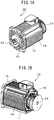
- FIGs. 1A and 1B illustrate external perspective views of a motor according to Example 1.
- 11 represents a motor cover
- 12 represents a rotating shaft
- 13 represents a cooling fan.
- the motor cover 11 has a motor casing 14 that houses a stator and a rotor.
- the motor cover 11 has a configuration in which the motor casing 14 has a cylindrical shape with opening portions formed on both sides, a flange 15 is provided at one opening portion, and an end bracket 16 is provided at another opening portion.
- the cooling fan 13 suctions external air from a suction hole provided at a side of an opposite surface of the end bracket 16 and generates cooling air through rotation of a rotary vane.
- the motor 10 may be an axial gap type in which the rotor and the stator are disposed to be opposite to each other in a direction parallel to the rotating shaft 12, or may be a radial gap type in which the stator is disposed at an outer diameter side of the rotor.
- An internal configuration of the motor casing 14 will be described below in detail.
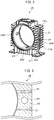
- Fig. 2 is a perspective view illustrating a configuration of the motor casing 14 detached from the motor cover 11.
- a plurality of cooling fins 21 that dissipate heat in the motor casing 14 are provided to project from outer circumferential surfaces of sides 20A and 20B and an underside 20C of the motor casing 14.
- the plurality of cooling fins 21 are each arrayed to extend side by side from one opening side to the other opening side of the motor casing 14. That is, the cooling fins 21 are provided to be aligned along the outer circumferential surfaces of the motor casing 14 in a state in which the fins are parallel to each other.
- an inner circumferential surface of the motor casing 14 has a fixing portion 24 formed for fixing the stator.
- Ribs 22 that extend in a circumferential direction of the motor casing 14 are provided to project from outer circumferential surfaces of the motor casing 14 at both sides 20A and 20B and the underside 20C of the motor casing 14.
- the ribs 22 intersect the cooling fins 21 so as to be formed integrally with the cooling fins at a substantially central position of the cooling fins 14 in a width direction.
- one line rib 22 is provided to intersect the cooling fins from the uppermost cooling fin 21a to the lowermost cooling fin 21b at each of the both sides 20A and 20B of the motor casing 14.
- the rib 22 is provided to intersect the cooling fins 21 from a left end side to a right end side in Fig. 2 at the substantially central position of the cooling fins 21 in the width direction.
- top portions 221 of the ribs 22 are all formed to be flush with top portions 211 of the cooling fins 21.
- the ribs 22 are provided on the outer circumferential surfaces of the motor casing 14, and thereby strength of the motor casing 14 increases in the circumferential direction thereof.
- Fig. 2 illustrates a configuration in which the rib 22 is provided to intersect the cooling fins from the uppermost cooling fin 21a to the lowermost cooling fin 21b at each of the both sides 20A and 20B of the motor casing 14.
- the motor 10 according to Example 1 is not limited thereto.
- the rib 22 may be provided from a position lower than the uppermost cooling fin 21a or may be provided from a position higher than the lowermost cooling fin 21b.
- one line rib 22 is provided at each center of the both sides 20A and 20B and the underside 20C of the motor casing 14.
- the configuration is not limited thereto, and multiple line of ribs may be provided at each of the both sides 20A and 20B and the underside 20C of the motor casing 14. Consequently, the strength of the motor casing 14 further increases.
- a configuration in which the ribs 22 are provided at the both sides 20A and 20B and the underside 20C of the motor casing 14 is illustrated.
- the motor 10 according to Example 1 is not limited thereto.
- the motor may have a configuration in which the rib 22 is provided at only one of the sides 20A and 20B of the motor casing 14 or a configuration in which the rib 22 is not provided at the underside 20C.
- the rib 22 is configured to be provided at the substantially central position of the cooling fins 21 in the width direction.
- the configuration is not limited thereto, and the rib 22 may be provided at a position close to the one opening side of the motor casing 14.
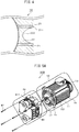
- Figs. 3 and 4 are enlarged views illustrating a part of the outer circumferential surface of the motor casing 14 of the motor according to Example 2.
- a vent hole 23 is provided at a part of the rib 22.
- a part of the rib 22 forms a recessed portion 222. That is, the recessed portion 222 at a part of the rib 22 is provided at a position lower than the top portion 211 of the cooling fin 21.
- the motor according to Example 2 has the same configuration as that of the motor 10 of Example 1 except for the description provided above, and thus the description thereof is omitted.
- Example 3 a manufacturing method suitable for preparing the motor casing 14 (refer to Fig. 2 ) of the motor 10 according to Example 1 is described.
- the position of the rib 22 is the connection surface between the left sand mold and the right sand mold, and thus the burr is mainly formed at the position of the rib 22.
- a front surface of the rib 22 or top portions of the cooling fins 21 around the rib is mainly polished by a grinder or the like, and thereby it is possible to remove most of the burr.
- the front surface of the rib 22 and a front surface of the cooling fin 21 are polished by a grinder or the like, and thereby the top portion 221 of the rib 22 is formed to be flush with the top portions 211 of the cooling fins 21.
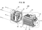
- FIGs. 5A and 5B are perspective views of a state in which a compression unit 40 and the motor 10 of a compressor 100 according to Example 4 are separated from each other.
- the compressor 100 includes the compression unit 40 that compresses a fluid and the motor 10 that drives the compression unit 40.
- the motor 10 the motor 10 (refer to Figs. 1A, 1B , and 2 ) described in Example 1 is used.
- the motor 10 a configuration, in which an axial gap type motor is employed, will be described as an example.
- the flange 15 of the motor cover 11 is fastened with a main-body casing 41 of the compression unit 40, and thereby the motor 10 can be provided integrally with the compression unit 40.
- the rotating shaft 12 is inserted at a predetermined position of the compression unit 40, and a fastening bolt 42 is inserted into a bolt inserting hole 151 provided in the flange 15 of the motor cover 11 and a bolt inserting hole 411 provided in the main-body casing 41, and thereby the flange 15 of the motor 10 and the main-body casing 41 can be fastened with each other.
- An insertion position of the rotating shaft 12 in the compression unit 40 will be described below.
- Fig. 6 illustrates a cross-sectional view of the compressor 100 having a configuration in which the motor 10 and the compression unit 40 illustrated in Figs. 5A and 5B are integrated with each other, when viewed from a side.
- a disk-shaped stator 31 is disposed between a pair of disk-shaped rotors 32.
- the rotating shaft 12 is provided to penetrate a central portion of the stator 31 and the rotors 32 and is rotatably supported by a main bearing 33 provided on a side of the compression unit 40 and an anti-load bearing 34 provided on an opposite side of the main bearing 33 with the stator 31 interposed between the main bearing and the anti-load bearing.
- the main bearing 33 and the anti-load bearing 34 are disposed to be concentric with each other.
- the rotating shaft 12 has an eccentric portion 12a at an end portion on a side of the main bearing 33.
- a gap is formed between the stator 31 and the rotor 32. Consequently, the stator 31 and the rotor 32 are housed in the motor casing 14 in a state of being disposed to be opposite to each other with the gap interposed therebetween in the direction parallel to the rotating shaft 12.
- Fig. 7 is a picture showing an inside of the motor casing 14 before a rotor 32 is installed, when viewed from an opening side of the motor casing 14.
- a surface of the stator 31 is illustrated in an exposed state, the surface being opposite to the rotor 32.
- the stator 31 has a configuration in which a plurality of iron core pieces 311 are disposed at equal intervals in the circumferential direction. A coil is wound around the iron core piece 311 via a nonmagnetic body.
- the iron core pieces 311 disposed in the circumferential direction are molded integrally with each other by being resin-molded with a resin material 312 so as to be fixed to the motor casing 14.
- the iron core piece 311 can be configured of an electromagnetic steel sheet or an amorphous metal.
- the iron core piece 311 is formed by the amorphous metal, a loss is significantly lower compared to another magnetic material, and magnetic permeability is high. Hence, high motor efficiency is obtained.
- the amorphous metal has high hardness, is brittle, and is used in a state of having a relatively thin sheet thickness, and thus the amorphous metal is unsuitable for a process such as punching.
- the stator 31 can be configured to have the iron core piece 311 obtained by stacking fan-shaped (refer to Fig. 7 ) foil strips that can be relatively easily produced.
- the axial gap type motor is suitable for using the amorphous metal since it is possible to produce the stator 31 without performing a punching process of a complex shape.
- the stator 31 When the axial gap type motor is manufactured, as described above, after the iron core pieces 311 are disposed in the circumferential direction in the motor casing 14, a method of forming the stator 31 by resin molding with the resin material 312 is often employed. In this case, during the resin molding, the resin material is injected into the motor casing 14 at a high temperature and high pressure of about 4 MPa (transfer mold). Hence, high pressure is loaded to the motor casing 14 from an inner circumferential side.
- the motor 10 described in Example 1 is used in the compressor 100 according to Example 4, and thus strength in the circumferential direction increases in the motor casing 14. Hence, an occurrence of deformation or a crack in the motor casing 14 due to the pressure applied during the resin molding can be inhibited, and it is possible to obtain an external appearance suitable as the motor 10.
- the compression unit 40 includes a fixed scroll 43 and a turning scroll 44 disposed to be opposite to the fixed scroll 43.
- the fixed scroll 43 and the turning scroll 44 are accommodated in the main-body casing 41.
- the main-body casing 41 is a cylindrical body having opening portions at both ends of the main-body casing, the fixed scroll 43 is attached to one opening portion, and the motor 10 is attached to another opening portion 49 (refer to Fig. 5B ).
- the fixed scroll 43 and the turning scroll 44 have spiral lap portions 43B and 44B formed on front surfaces of mirror plates 43A and 44A, respectively.
- the lap portion 43B of the fixed scroll 43 and the lap portion 44B of the turning scroll 44 intermesh with each other, and thereby a compression chamber 45 is formed.
- the lap portion 43B of the fixed scroll 43 and the lap portion 44B of the turning scroll 44 have tip seals 43C and 44C, respectively, at front ends of the lap portions.
- a back surface of the turning scroll 44 has a turning bearing 47 provided in a boss portion 46.
- the eccentric portion 12a of the rotating shaft 12 is inserted into the turning bearing 47, and thereby the eccentric portion 12a of the rotating shaft 12 is supported by the turning scroll 44.
- the eccentric portion 12a of the rotating shaft 12 performs an eccentric motion as the rotating shaft 12 performs a rotary motion.
- the turning scroll 44 connected to the eccentric portion 12a performs a turning motion.
- the compression chamber 45 demarcated between the lap portion 43B of the fixed scroll 43 and the lap portion 44B of the turning scroll 44 is continuously reduced. Consequently, a fluid introduced into the compression chamber 45 is compressed, and compressed air is discharged to the outside of the compression unit 40.
- one of a plurality of compression chambers 45 becomes an intake port of the fluid, and one of the plurality of compression chambers 45 becomes a discharge port of a compressed fluid.
- the eccentric portion 12a at an end portion of the rotating shaft 12 is directly connected to a back surface portion of the turning scroll 44, and a drive force of the rotating shaft 12 is directly transmitted to the turning scroll 44.
- the turning scroll 44 performs the turning motion. Therefore, in order to realize a smooth turning motion of the turning scroll 44, the eccentric portion 12a of the rotating shaft 12 needs to be supported by the back surface of the turning scroll 44 in an appropriate state. Therefore, installation positions of respective members such as the main bearing 33, the anti-load bearing 34, and the turning bearing 47 are adjusted with high accuracy in a design stage.
- the motor in which the ribs 22 are provided on the outer circumferential surfaces of the motor casing 14 is used as the motor 10. Therefore, the strength of the motor casing 14 in the circumferential direction increases, and thus the occurrence of deformation, a crack, or the like is inhibited. Hence, such a negative effect described above is unlikely to occur, and thus it is possible to realize a smooth compression operation in a so-called single shaft type of scroll compressor 100.
- Example 4 as the motor 10, a configuration, in which the motor 10 according to Example 1 is used, is described as an example.
- the compressor 100 according to Example 4 is not limited thereto, and the compressor can be configured to use the motor described in Example 2.
- Example 4 the configuration of the compressor 100 including the scroll type compression unit 40 is described as an example, the invention is not limited thereto.
Landscapes
- Engineering & Computer Science (AREA)
- Power Engineering (AREA)
- Physics & Mathematics (AREA)
- Thermal Sciences (AREA)
- Mechanical Engineering (AREA)
- General Engineering & Computer Science (AREA)
- Compressor (AREA)
- Connection Of Motors, Electrical Generators, Mechanical Devices, And The Like (AREA)
- Rotary Pumps (AREA)
- Applications Or Details Of Rotary Compressors (AREA)
- Iron Core Of Rotating Electric Machines (AREA)
- Insulation, Fastening Of Motor, Generator Windings (AREA)
- Motor Or Generator Frames (AREA)
Abstract
Description
- The present invention relates to a motor and a compressor that uses the motor.
- A motor that drives a compressor has a configuration in which a rotor and a stator that drives the rotor are integrally accommodated in a motor casing. For example, Patent Document 1 discloses a compressor in which a rotor and a stator are accommodated in a motor casing and which includes a drive shaft that penetrates the rotor so as to drive a turning scroll.
- Patent Document 1:
JP 2015-68248 A - In the above-described motor, a high temperature or high pressure may be applied to the motor casing during an operation or manufacture. For example, when the stator is installed to be molded with a resin press-fitted in the motor casing, a high temperature or high pressure may be applied to the motor casing at the time of a resin press-fitting, and thus the motor casing may be distorted. In this manner, there may be a demand for a motor casing having higher strength depending on specifications of a motor or a condition during an operation.
- Hence, an object of the invention is to provide a motor for which high strength can be obtained in a motor casing and a compressor that uses the motor.
- A preferred embodiment of a motor according to the invention includes: a rotating shaft provided in a rotatable manner; a rotor that rotates integrally with the rotating shaft; a stator that rotationally drives the rotor; and a motor casing that is a cylindrical body for accommodating the rotor and the stator, and has, on an outer circumferential surface of the motor casing, ribs extending in a circumferential direction.
- In addition, the invention is configured also as a compressor that uses the above-described motor.
- According to the invention, it is possible to realize a motor for which high strength can be obtained in a motor casing and a compressor that uses the motor.
-
-
Fig. 1A is an external perspective view of a motor according to Example 1. -
Fig. 1B is an external perspective view of the motor according to Example 1. -
Fig. 2 is a perspective view illustrating a configuration of amotor casing 14 detached from amotor cover 11. -
Fig. 3 is an enlarged view illustrating a part of an outer circumferential surface of amotor casing 14 of a motor according to Example 2. -
Fig. 4 is an enlarged view illustrating a part of an outer circumferential surface of amotor casing 14 of a motor according to Example 3. -
Fig. 5A is a perspective view illustrating a state in which acompression unit 40 and amotor 10 of acompressor 100 according to Example 5 are separated from each other. -
Fig. 5B is a perspective view illustrating a state in which thecompression unit 40 and themotor 10 of thecompressor 100 according to Example 5 are separated from each other. -
Fig. 6 illustrates a cross-sectional view of thecompressor 100 having a configuration in which themotor 10 and thecompression unit 40 illustrated inFigs. 5A and5B are integrated with each other, when viewed from a side. -
Fig. 7 is a picture showing an inside of themotor casing 14 before arotor 32 is installed, when viewed from an opening side of themotor casing 14. - With reference to
Figs. 1A, 1B , and2 , a configuration of amotor 10 according to Example 1 is described.Figs. 1A and 1B illustrate external perspective views of a motor according to Example 1. InFigs. 1A and 1B , 11 represents a motor cover, 12 represents a rotating shaft, and 13 represents a cooling fan. Themotor cover 11 has amotor casing 14 that houses a stator and a rotor. Themotor cover 11 has a configuration in which themotor casing 14 has a cylindrical shape with opening portions formed on both sides, aflange 15 is provided at one opening portion, and anend bracket 16 is provided at another opening portion. Thecooling fan 13 suctions external air from a suction hole provided at a side of an opposite surface of theend bracket 16 and generates cooling air through rotation of a rotary vane. - The
motor 10 may be an axial gap type in which the rotor and the stator are disposed to be opposite to each other in a direction parallel to the rotatingshaft 12, or may be a radial gap type in which the stator is disposed at an outer diameter side of the rotor. An internal configuration of themotor casing 14 will be described below in detail. -
Fig. 2 is a perspective view illustrating a configuration of themotor casing 14 detached from themotor cover 11. As illustrated inFig. 2 , a plurality ofcooling fins 21 that dissipate heat in themotor casing 14 are provided to project from outer circumferential surfaces ofsides motor casing 14. The plurality ofcooling fins 21 are each arrayed to extend side by side from one opening side to the other opening side of themotor casing 14. That is, thecooling fins 21 are provided to be aligned along the outer circumferential surfaces of themotor casing 14 in a state in which the fins are parallel to each other. Incidentally, an inner circumferential surface of themotor casing 14 has afixing portion 24 formed for fixing the stator. -
Ribs 22 that extend in a circumferential direction of themotor casing 14 are provided to project from outer circumferential surfaces of themotor casing 14 at bothsides motor casing 14. Theribs 22 intersect thecooling fins 21 so as to be formed integrally with the cooling fins at a substantially central position of thecooling fins 14 in a width direction. - In an example illustrated in
Fig. 2 , oneline rib 22 is provided to intersect the cooling fins from theuppermost cooling fin 21a to thelowermost cooling fin 21b at each of the bothsides motor casing 14. In addition, although not illustrated in the drawings, similarly, at the underside 20C of themotor casing 14, therib 22 is provided to intersect thecooling fins 21 from a left end side to a right end side inFig. 2 at the substantially central position of thecooling fins 21 in the width direction. - In an example illustrated in
Fig. 2 ,top portions 221 of theribs 22 are all formed to be flush withtop portions 211 of thecooling fins 21. - As described above, the
ribs 22 are provided on the outer circumferential surfaces of themotor casing 14, and thereby strength of themotor casing 14 increases in the circumferential direction thereof. - Incidentally,
Fig. 2 illustrates a configuration in which therib 22 is provided to intersect the cooling fins from theuppermost cooling fin 21a to thelowermost cooling fin 21b at each of the bothsides motor casing 14. Themotor 10 according to Example 1 is not limited thereto. Therib 22 may be provided from a position lower than theuppermost cooling fin 21a or may be provided from a position higher than thelowermost cooling fin 21b. - In addition, in the example illustrated in
Fig. 2 , oneline rib 22 is provided at each center of the bothsides motor casing 14. However, the configuration is not limited thereto, and multiple line of ribs may be provided at each of the bothsides motor casing 14. Consequently, the strength of themotor casing 14 further increases. - In addition, in the example illustrated in
Fig. 2 , a configuration in which theribs 22 are provided at the bothsides motor casing 14 is illustrated. Themotor 10 according to Example 1 is not limited thereto. The motor may have a configuration in which therib 22 is provided at only one of thesides motor casing 14 or a configuration in which therib 22 is not provided at the underside 20C. - In addition, in the configuration illustrated in
Fig. 1 , therib 22 is configured to be provided at the substantially central position of thecooling fins 21 in the width direction. However, the configuration is not limited thereto, and therib 22 may be provided at a position close to the one opening side of themotor casing 14. - Next, a motor according to Example 2 will be described with reference to
Figs. 3 and4 .Figs. 3 and4 are enlarged views illustrating a part of the outer circumferential surface of themotor casing 14 of the motor according to Example 2. In an example illustrated inFig. 3 , avent hole 23 is provided at a part of therib 22. In addition, in an example illustrated inFig. 4 , a part of therib 22 forms a recessedportion 222. That is, the recessedportion 222 at a part of therib 22 is provided at a position lower than thetop portion 211 of the coolingfin 21. - According to configurations illustrated in
Figs. 3 and4 , external air around themotor casing 14 can pass through thehole 23 or the recessedportion 222 of therib 22, and thus a suction efficiency of the external air from the suction hole of the coolingfan 13 improves. Hence, a cooling efficiency by the coolingfan 13 can be improved. Incidentally, the motor according to Example 2 has the same configuration as that of themotor 10 of Example 1 except for the description provided above, and thus the description thereof is omitted. - In Example 3, a manufacturing method suitable for preparing the motor casing 14 (refer to
Fig. 2 ) of themotor 10 according to Example 1 is described. - (Process 1) First, a sand mold is prepared. Preparation of the sand mold is as follows. Dies are prepared to produce shapes of outer circumferential surfaces corresponding to regions halved at the position of the
rib 22 of themotor casing 14 illustrated inFig. 2 , and the dies are each pressed against sand such that a left sand mold and a right sand mold as main molds are prepared. Further, a core for preparing a shape of the inner circumferential surface of themotor casing 14 is prepared by using the same sand as that used to prepare the main molds. - (Process 2) Next, the left sand mold and the right sand mold are connected to surround the core prepared in (Process 1) such that division surfaces thereof are joined together.
- (Process 3) Next, molten metal is poured in the sand molds connected in (Process 2), remains as is for a predetermined time, and is cooled. For example, molten Al can be used as the molten metal.
- (Process 4) After the molten metal in the sand molds is cooled and solidified, the sand molds are removed such that a metal-molded body is taken out. It is possible to break down to remove the sand molds while pulling out both the left sand mold and the right sand mold in a vertical direction with respect to an opening plane of the
motor casing 14. - (Process 5) Subsequently, a burr of the metal-molded body is polished and removed. Incidentally, the burr is generated when a part of the molten metal injected into the sand mold is solidified in a state of flowing out from a connection surface or the like of the sand mold.
- In the metal-molded body prepared as described above, the position of the
rib 22 is the connection surface between the left sand mold and the right sand mold, and thus the burr is mainly formed at the position of therib 22. Hence, a front surface of therib 22 or top portions of the coolingfins 21 around the rib is mainly polished by a grinder or the like, and thereby it is possible to remove most of the burr. Hence, it is possible to significantly reduce time and effort for polishing a back surface of the coolingfin 21. The front surface of therib 22 and a front surface of the coolingfin 21 are polished by a grinder or the like, and thereby thetop portion 221 of therib 22 is formed to be flush with thetop portions 211 of the coolingfins 21. - Next, a configuration of a compressor according to Example 4 will be described with reference to
Figs. 5A ,5B ,6 , and7 .Figs. 5A and5B are perspective views of a state in which acompression unit 40 and themotor 10 of acompressor 100 according to Example 4 are separated from each other. As illustrated inFigs. 5A and5B , thecompressor 100 includes thecompression unit 40 that compresses a fluid and themotor 10 that drives thecompression unit 40. As themotor 10, the motor 10 (refer toFigs. 1A, 1B , and2 ) described in Example 1 is used. In the following description, as themotor 10, a configuration, in which an axial gap type motor is employed, will be described as an example. - As illustrated in
Figs. 5A and5B , theflange 15 of themotor cover 11 is fastened with a main-body casing 41 of thecompression unit 40, and thereby themotor 10 can be provided integrally with thecompression unit 40. Specifically, the rotatingshaft 12 is inserted at a predetermined position of thecompression unit 40, and afastening bolt 42 is inserted into abolt inserting hole 151 provided in theflange 15 of themotor cover 11 and abolt inserting hole 411 provided in the main-body casing 41, and thereby theflange 15 of themotor 10 and the main-body casing 41 can be fastened with each other. An insertion position of therotating shaft 12 in thecompression unit 40 will be described below. -
Fig. 6 illustrates a cross-sectional view of thecompressor 100 having a configuration in which themotor 10 and thecompression unit 40 illustrated inFigs. 5A and5B are integrated with each other, when viewed from a side. In themotor casing 14, a disk-shapedstator 31 is disposed between a pair of disk-shapedrotors 32. The rotatingshaft 12 is provided to penetrate a central portion of thestator 31 and therotors 32 and is rotatably supported by amain bearing 33 provided on a side of thecompression unit 40 and ananti-load bearing 34 provided on an opposite side of themain bearing 33 with thestator 31 interposed between the main bearing and the anti-load bearing. Themain bearing 33 and theanti-load bearing 34 are disposed to be concentric with each other. The rotatingshaft 12 has aneccentric portion 12a at an end portion on a side of themain bearing 33. - A gap is formed between the
stator 31 and therotor 32. Consequently, thestator 31 and therotor 32 are housed in themotor casing 14 in a state of being disposed to be opposite to each other with the gap interposed therebetween in the direction parallel to therotating shaft 12. -
Fig. 7 is a picture showing an inside of themotor casing 14 before arotor 32 is installed, when viewed from an opening side of themotor casing 14. InFig. 7 , a surface of thestator 31 is illustrated in an exposed state, the surface being opposite to therotor 32. - The
stator 31 has a configuration in which a plurality ofiron core pieces 311 are disposed at equal intervals in the circumferential direction. A coil is wound around theiron core piece 311 via a nonmagnetic body. Theiron core pieces 311 disposed in the circumferential direction are molded integrally with each other by being resin-molded with aresin material 312 so as to be fixed to themotor casing 14. For example, theiron core piece 311 can be configured of an electromagnetic steel sheet or an amorphous metal. - When current flows in the coil wound around the
iron core piece 311 of thestator 31, a rotating force is applied to therotor 32 due to a magnetic field generated by thestator 31 and therotor 32. The rotatingshaft 12 rotates as therotor 32 rotates. - When the
iron core piece 311 is formed by the amorphous metal, a loss is significantly lower compared to another magnetic material, and magnetic permeability is high. Hence, high motor efficiency is obtained. On the other hand, the amorphous metal has high hardness, is brittle, and is used in a state of having a relatively thin sheet thickness, and thus the amorphous metal is unsuitable for a process such as punching. - In the axial gap type motor, the
stator 31 can be configured to have theiron core piece 311 obtained by stacking fan-shaped (refer toFig. 7 ) foil strips that can be relatively easily produced. Hence, the axial gap type motor is suitable for using the amorphous metal since it is possible to produce thestator 31 without performing a punching process of a complex shape. - When the axial gap type motor is manufactured, as described above, after the
iron core pieces 311 are disposed in the circumferential direction in themotor casing 14, a method of forming thestator 31 by resin molding with theresin material 312 is often employed. In this case, during the resin molding, the resin material is injected into themotor casing 14 at a high temperature and high pressure of about 4 MPa (transfer mold). Hence, high pressure is loaded to themotor casing 14 from an inner circumferential side. - The
motor 10 described in Example 1 is used in thecompressor 100 according to Example 4, and thus strength in the circumferential direction increases in themotor casing 14. Hence, an occurrence of deformation or a crack in themotor casing 14 due to the pressure applied during the resin molding can be inhibited, and it is possible to obtain an external appearance suitable as themotor 10. - As illustrated in
Fig. 6 , thecompression unit 40 includes a fixedscroll 43 and aturning scroll 44 disposed to be opposite to the fixedscroll 43. The fixedscroll 43 and the turningscroll 44 are accommodated in the main-body casing 41. - The main-
body casing 41 is a cylindrical body having opening portions at both ends of the main-body casing, the fixedscroll 43 is attached to one opening portion, and themotor 10 is attached to another opening portion 49 (refer toFig. 5B ). - The fixed
scroll 43 and the turningscroll 44 havespiral lap portions mirror plates lap portion 43B of the fixedscroll 43 and thelap portion 44B of the turningscroll 44 intermesh with each other, and thereby acompression chamber 45 is formed. Thelap portion 43B of the fixedscroll 43 and thelap portion 44B of the turningscroll 44 havetip seals - A back surface of the turning
scroll 44 has a turning bearing 47 provided in aboss portion 46. Theeccentric portion 12a of therotating shaft 12 is inserted into the turningbearing 47, and thereby theeccentric portion 12a of therotating shaft 12 is supported by the turningscroll 44. - The
eccentric portion 12a of therotating shaft 12 performs an eccentric motion as the rotatingshaft 12 performs a rotary motion. Hence, when the rotatingshaft 12 is rotatably driven by themotor 10, the turningscroll 44 connected to theeccentric portion 12a performs a turning motion. When the turningscroll 44 performs the turning motion, thecompression chamber 45 demarcated between thelap portion 43B of the fixedscroll 43 and thelap portion 44B of the turningscroll 44 is continuously reduced. Consequently, a fluid introduced into thecompression chamber 45 is compressed, and compressed air is discharged to the outside of thecompression unit 40. Incidentally, although omitted in the drawings, one of a plurality ofcompression chambers 45 becomes an intake port of the fluid, and one of the plurality ofcompression chambers 45 becomes a discharge port of a compressed fluid. - In the
compressor 100 described above, theeccentric portion 12a at an end portion of therotating shaft 12 is directly connected to a back surface portion of the turningscroll 44, and a drive force of therotating shaft 12 is directly transmitted to the turningscroll 44. In this manner, the turningscroll 44 performs the turning motion. Therefore, in order to realize a smooth turning motion of the turningscroll 44, theeccentric portion 12a of therotating shaft 12 needs to be supported by the back surface of the turningscroll 44 in an appropriate state. Therefore, installation positions of respective members such as themain bearing 33, theanti-load bearing 34, and the turning bearing 47 are adjusted with high accuracy in a design stage. In this case, when themotor casing 14 is distorted during manufacturing of themotor 10, the installation positions are shifted, and therotating shaft 12 is not supported by thecompression unit 40 in the appropriate state. In this case, the turning motion of the turningscroll 44 is hindered in some cases. - In the
compressor 100 according to Example 4, the motor in which theribs 22 are provided on the outer circumferential surfaces of themotor casing 14 is used as themotor 10. Therefore, the strength of themotor casing 14 in the circumferential direction increases, and thus the occurrence of deformation, a crack, or the like is inhibited. Hence, such a negative effect described above is unlikely to occur, and thus it is possible to realize a smooth compression operation in a so-called single shaft type ofscroll compressor 100. - In Example 4 described above, as the
motor 10, a configuration, in which themotor 10 according to Example 1 is used, is described as an example. Thecompressor 100 according to Example 4 is not limited thereto, and the compressor can be configured to use the motor described in Example 2. - In addition, in Example 4, the configuration of the
compressor 100 including the scrolltype compression unit 40 is described as an example, the invention is not limited thereto. For example, it is possible to employ a configuration obtained by combining a reciprocal compression unit with themotor 10 according to Example 1. -
- 10
- Motor
- 100
- Compressor
- 11
- Motor cover
- 12
- Rotating shaft
- 12a
- Eccentric portion
- 13
- Cooling fan
- 14
- Motor casing
- 15
- Flange
- 151, 411
- Bolt inserting hole
- 16
- End bracket
- 20A, 20B
- Side
- 20C
- Underside
- 21
- Cooling fin
- 21a
- Uppermost cooling fin
- 21b
- Lowermost cooling fin
- 211
- Top portion
- 22
- Rib
- 221
- Top portion
- 23
- Hole
- 31
- Stator
- 311
- Iron core piece
- 312
- Resin material
- 32
- Rotor
- 33
- Main bearing
- 34
- Anti-load bearing
- 40
- Compression unit
- 41
- Main-body casing
- 42
- Fastening bolt
- 43
- Fixed scroll
- 44
- Turning scroll
- 43A, 44A
- Mirror plate
- 43B, 44B
- Spiral lap portion
- 43C, 44C
- Tip seal
- 45
- Compression chamber
- 46
- Boss portion
- 47
- Turning bearing
Claims (14)
- A motor comprising:a rotating shaft provided in a rotatable manner;a rotor that rotates integrally with the rotating shaft;a stator that rotationally drives the rotor; anda motor casing that is a cylindrical body for accommodating the rotor and the stator, and has, on an outer circumferential surface of the motor casing, ribs extending in a circumferential direction.
- The motor according to claim 1,
wherein the motor casing has opening portions on both sides of the motor casing and a plurality of cooling fins that are arrayed on the outer circumferential surface of the motor casing, the cooling fins extending side by side from one opening side to the other opening side of the motor casing, and
wherein the ribs intersect the cooling fins so as to be formed integrally with the cooling fins. - The motor according to claim 2,
wherein top portions of the ribs are provided to be flush with top portions of the cooling fins. - The motor according to claim 1,
wherein the ribs have a hole. - The motor according to claim 1,
wherein the ribs have a recessed shape. - The motor according to claim 1,
wherein the ribs are provided at a side of the motor casing. - The motor according to claim 6,
wherein the ribs are provided on an underside of the motor casing. - The motor according to claim 1,
wherein the stator has a configuration in which a plurality of iron core pieces around which respective coils are wound are disposed in a circumferential direction and the iron core pieces are resin-molded, and
wherein the stator and the rotor are disposed to be opposite to each other with a gap interposed between the stator and the rotor in a direction parallel to the rotating shaft. - The motor according to claim 8,
wherein the iron core pieces are formed of an amorphous metal. - A compressor comprising:a compression unit that compresses a fluid; anda motor that drives the compression unit,wherein the motor includesa rotating shaft provided in a rotatable manner,a rotor that rotates integrally with the rotating shaft,a stator that rotationally drives the rotor, anda motor casing that is a cylindrical body for accommodating the rotor and the stator, and has, on an outer circumferential surface of the motor casing, ribs extending in a circumferential direction.
- The compressor according to claim 10,
wherein the motor casing has opening portions on both sides of the motor casing and a plurality of cooling fins that are arrayed on an outer circumferential surface of the motor casing, the cooling fins extending side by side from one opening side to the other opening side of the motor casing, and
wherein the ribs intersect the cooling fins so as to be formed integrally with the cooling fins. - The compressor according to claim 10,
wherein the compression unit has a turning scroll, which supports an end portion of the rotating shaft and performs a turning motion due to rotation of the rotating shaft, and a fixed scroll disposed to be opposite to the turning scroll,
wherein the turning scroll and the fixed scroll have respective mirror plates and spiral lap portions provided to be upright on the mirror plates, and the lap portions are provided to intermesh with each other. - The compressor according to claim 10,
wherein the stator has a configuration in which a plurality of iron core pieces around which respective coils are wound are disposed in a circumferential direction and the iron core pieces are resin-molded, and
wherein the stator and the rotor are disposed to be opposite to each other with a gap interposed between the stator and the rotor in a direction parallel to the rotating shaft. - The compressor according to claim 13,
wherein the iron core pieces are formed of an amorphous metal.
Applications Claiming Priority (1)
| Application Number | Priority Date | Filing Date | Title |
|---|---|---|---|
| PCT/JP2017/002485 WO2018138795A1 (en) | 2017-01-25 | 2017-01-25 | Motor and compressor that uses same |
Publications (3)
| Publication Number | Publication Date |
|---|---|
| EP3576261A1 true EP3576261A1 (en) | 2019-12-04 |
| EP3576261A4 EP3576261A4 (en) | 2020-08-19 |
| EP3576261B1 EP3576261B1 (en) | 2024-03-27 |
Family
ID=62977957
Family Applications (1)
| Application Number | Title | Priority Date | Filing Date |
|---|---|---|---|
| EP17894314.8A Active EP3576261B1 (en) | 2017-01-25 | 2017-01-25 | Motor and compressor that uses same |
Country Status (5)
| Country | Link |
|---|---|
| US (1) | US11251677B2 (en) |
| EP (1) | EP3576261B1 (en) |
| JP (1) | JP7046011B2 (en) |
| CN (2) | CN110226278A (en) |
| WO (1) | WO2018138795A1 (en) |
Families Citing this family (4)
| Publication number | Priority date | Publication date | Assignee | Title |
|---|---|---|---|---|
| USD918141S1 (en) * | 2018-06-22 | 2021-05-04 | Siemens Aktiengesellschaft | Electric motor |
| USD909301S1 (en) * | 2018-11-19 | 2021-02-02 | Saccardo Elettromeccanica S.R.L. | Electric motor |
| JPWO2021044853A1 (en) * | 2019-09-03 | 2021-03-11 | ||
| CN111509910B (en) * | 2020-05-07 | 2022-11-11 | 北京理工大学 | Motor stator and motor |
Family Cites Families (31)
| Publication number | Priority date | Publication date | Assignee | Title |
|---|---|---|---|---|
| JPS5032402A (en) | 1973-07-27 | 1975-03-29 | ||
| JPS5543386U (en) | 1978-09-12 | 1980-03-21 | ||
| US4867657A (en) | 1988-06-29 | 1989-09-19 | American Standard Inc. | Scroll compressor with axially balanced shaft |
| JPH0247895A (en) | 1988-08-09 | 1990-02-16 | Fujitsu Ltd | Heat dissipation plate |
| JP2782858B2 (en) | 1989-10-31 | 1998-08-06 | 松下電器産業株式会社 | Scroll gas compressor |
| US5334897A (en) | 1993-05-24 | 1994-08-02 | North American Philips Corporation | Electric motor with encased housing |
| JPH07184351A (en) * | 1993-12-24 | 1995-07-21 | Hitachi Ltd | Rotating electric machine |
| JP3184764B2 (en) * | 1995-06-26 | 2001-07-09 | 株式会社東芝 | Rotating electric machine stator |
| JP3651169B2 (en) | 1997-04-02 | 2005-05-25 | 富士電機機器制御株式会社 | Fully enclosed external fan-type rotating electric machine |
| JP4644909B2 (en) * | 2000-05-15 | 2011-03-09 | パナソニック電工株式会社 | Motor fin structure |
| JP4536959B2 (en) | 2001-07-02 | 2010-09-01 | 株式会社日立製作所 | Scroll type fluid machine |
| JP2003021065A (en) | 2001-07-06 | 2003-01-24 | Tokico Ltd | Compressor |
| AT504056B1 (en) * | 2003-10-06 | 2009-08-15 | Traktionssysteme Austria Gmbh | CAPSULATED, ELECTRIC MACHINE |
| JP4700439B2 (en) | 2005-08-25 | 2011-06-15 | 富士重工業株式会社 | Electric motor |
| JP2007189812A (en) | 2006-01-12 | 2007-07-26 | Toyota Motor Corp | Inner rotor type brushless motor |
| JP4856999B2 (en) * | 2006-03-24 | 2012-01-18 | 日立アプライアンス株式会社 | motor |
| US7579724B2 (en) * | 2006-06-02 | 2009-08-25 | General Electric Company | Methods and apparatus for using an electrical machine to transport fluids through a pipeline |
| JP5769332B2 (en) * | 2010-06-02 | 2015-08-26 | アネスト岩田株式会社 | Scroll expander |
| JP2012246819A (en) | 2011-05-27 | 2012-12-13 | Hitachi Appliances Inc | Compressor and refrigerating cycle apparatus |
| JP5798470B2 (en) * | 2011-12-13 | 2015-10-21 | 住友重機械工業株式会社 | Motor frame structure |
| JP5942585B2 (en) * | 2012-05-16 | 2016-06-29 | コベルコ建機株式会社 | Electric motor and manufacturing method thereof |
| JP2015006083A (en) | 2013-06-21 | 2015-01-08 | 株式会社東芝 | Stator, stator manufacturing method |
| JP6073763B2 (en) * | 2013-08-30 | 2017-02-01 | 株式会社日立産機システム | Axial gap type permanent magnet synchronous motor |
| JP6153836B2 (en) | 2013-09-30 | 2017-06-28 | 株式会社日立産機システム | Scroll type fluid machine |
| JP6165576B2 (en) | 2013-09-30 | 2017-07-19 | 株式会社日立産機システム | Scroll type fluid machine |
| WO2015162819A1 (en) | 2014-04-25 | 2015-10-29 | 株式会社日立産機システム | Axial air-gap rotary electric machine |
| JP6368591B2 (en) | 2014-08-29 | 2018-08-01 | 新日本無線株式会社 | Charge amplifier circuit |
| DE102015211048A1 (en) * | 2015-06-16 | 2016-12-22 | Siemens Aktiengesellschaft | Electric machine |
| JP2017017892A (en) | 2015-07-02 | 2017-01-19 | 株式会社プロドローン | Motor housing for multicopter and waterproof motor using the same |
| DE202015105804U1 (en) * | 2015-11-02 | 2015-12-18 | Ebm-Papst Mulfingen Gmbh & Co. Kg | Electric motor with improved cooling |
| WO2017208290A1 (en) * | 2016-05-30 | 2017-12-07 | 三菱電機株式会社 | Stator, electric motor, compressor, refrigeration air-conditioner |
-
2017
- 2017-01-25 EP EP17894314.8A patent/EP3576261B1/en active Active
- 2017-01-25 US US16/476,892 patent/US11251677B2/en active Active
- 2017-01-25 CN CN201780084600.2A patent/CN110226278A/en active Pending
- 2017-01-25 CN CN202211316293.5A patent/CN115514138A/en active Pending
- 2017-01-25 WO PCT/JP2017/002485 patent/WO2018138795A1/en not_active Ceased
- 2017-01-25 JP JP2018563984A patent/JP7046011B2/en active Active
Also Published As
| Publication number | Publication date |
|---|---|
| EP3576261B1 (en) | 2024-03-27 |
| CN115514138A (en) | 2022-12-23 |
| EP3576261A4 (en) | 2020-08-19 |
| JPWO2018138795A1 (en) | 2019-06-27 |
| US11251677B2 (en) | 2022-02-15 |
| WO2018138795A1 (en) | 2018-08-02 |
| US20190334408A1 (en) | 2019-10-31 |
| CN110226278A (en) | 2019-09-10 |
| JP7046011B2 (en) | 2022-04-01 |
Similar Documents
| Publication | Publication Date | Title |
|---|---|---|
| US7541702B2 (en) | Brushless fan motor | |
| US10320260B2 (en) | Canned motor and vacuum pump | |
| US11251677B2 (en) | Motor and compressor that uses same | |
| US20150162791A1 (en) | Rotor and motor including the same | |
| US20230412021A1 (en) | Rotor and electric machine of an electric vehicle | |
| CN109578300B (en) | Centrifugal fan | |
| US9467011B2 (en) | Mold stator, electric motor, and air-conditioner outdoor unit | |
| US9787150B2 (en) | Rotor of brushless motor | |
| CN101453154B (en) | Motor | |
| US11469643B2 (en) | Scroll compressor having axial fan and discharge brush | |
| WO2017202318A1 (en) | Punching plate for motor rotor, motor rotor, motor, and electric vehicle | |
| JP2020115015A (en) | Impeller and supercharger | |
| JP2009240146A (en) | Rotor of brushless dc motor, compressor equipped with rotor, and apparatus with compressor mounted thereon | |
| CN108292872B (en) | Rotor, motor, air conditioner, and method for manufacturing rotor | |
| US10566873B2 (en) | Rotating electrical machine having means to secure plating to cover a flow passage | |
| WO2017202319A1 (en) | Permanent magnet synchronous motor and electric vehicle | |
| KR101628961B1 (en) | Rotor for axial flux permanent magnet motor and the motor including thereof | |
| JP5871469B2 (en) | Electric motor and electric compressor using the same | |
| CN113224879A (en) | Compressor special motor capable of never demagnetizing | |
| CN113644765A (en) | Air-cooled permanent magnet synchronous motor | |
| JP3219917U (en) | Rotor used for compressor | |
| US20230358234A1 (en) | Scroll compressor | |
| US20120014818A1 (en) | Fan structure | |
| IT202300001392U1 (en) | FAN ASSEMBLY INCLUDING OPTIMIZED MOTOR | |
| JP2005065359A (en) | Cooling fan for rotating electrical machine and manufacturing method thereof |
Legal Events
| Date | Code | Title | Description |
|---|---|---|---|
| STAA | Information on the status of an ep patent application or granted ep patent |
Free format text: STATUS: THE INTERNATIONAL PUBLICATION HAS BEEN MADE |
|
| PUAI | Public reference made under article 153(3) epc to a published international application that has entered the european phase |
Free format text: ORIGINAL CODE: 0009012 |
|
| STAA | Information on the status of an ep patent application or granted ep patent |
Free format text: STATUS: REQUEST FOR EXAMINATION WAS MADE |
|
| 17P | Request for examination filed |
Effective date: 20190826 |
|
| AK | Designated contracting states |
Kind code of ref document: A1 Designated state(s): AL AT BE BG CH CY CZ DE DK EE ES FI FR GB GR HR HU IE IS IT LI LT LU LV MC MK MT NL NO PL PT RO RS SE SI SK SM TR |
|
| AX | Request for extension of the european patent |
Extension state: BA ME |
|
| DAV | Request for validation of the european patent (deleted) | ||
| DAX | Request for extension of the european patent (deleted) | ||
| A4 | Supplementary search report drawn up and despatched |
Effective date: 20200721 |
|
| RIC1 | Information provided on ipc code assigned before grant |
Ipc: H02K 1/27 20060101ALI20200715BHEP Ipc: H02K 16/02 20060101ALI20200715BHEP Ipc: H02K 1/02 20060101ALI20200715BHEP Ipc: H02K 5/18 20060101AFI20200715BHEP Ipc: H02K 7/14 20060101ALI20200715BHEP Ipc: H02K 3/34 20060101ALI20200715BHEP Ipc: H02K 9/06 20060101ALI20200715BHEP |
|
| STAA | Information on the status of an ep patent application or granted ep patent |
Free format text: STATUS: EXAMINATION IS IN PROGRESS |
|
| 17Q | First examination report despatched |
Effective date: 20211129 |
|
| REG | Reference to a national code |
Ref country code: DE Ref legal event code: R079 Free format text: PREVIOUS MAIN CLASS: H02K0005180000 Ipc: H02K0001279500 Ref country code: DE Ref legal event code: R079 Ref document number: 602017080491 Country of ref document: DE Free format text: PREVIOUS MAIN CLASS: H02K0005180000 Ipc: H02K0001279500 |
|
| RIC1 | Information provided on ipc code assigned before grant |
Ipc: H02K 16/02 20060101ALI20230731BHEP Ipc: H02K 3/34 20060101ALI20230731BHEP Ipc: H02K 1/02 20060101ALI20230731BHEP Ipc: H02K 9/06 20060101ALI20230731BHEP Ipc: H02K 7/14 20060101ALI20230731BHEP Ipc: H02K 5/18 20060101ALI20230731BHEP Ipc: H02K 1/2795 20220101AFI20230731BHEP |
|
| GRAP | Despatch of communication of intention to grant a patent |
Free format text: ORIGINAL CODE: EPIDOSNIGR1 |
|
| STAA | Information on the status of an ep patent application or granted ep patent |
Free format text: STATUS: GRANT OF PATENT IS INTENDED |
|
| INTG | Intention to grant announced |
Effective date: 20231020 |
|
| GRAS | Grant fee paid |
Free format text: ORIGINAL CODE: EPIDOSNIGR3 |
|
| GRAA | (expected) grant |
Free format text: ORIGINAL CODE: 0009210 |
|
| STAA | Information on the status of an ep patent application or granted ep patent |
Free format text: STATUS: THE PATENT HAS BEEN GRANTED |
|
| AK | Designated contracting states |
Kind code of ref document: B1 Designated state(s): AL AT BE BG CH CY CZ DE DK EE ES FI FR GB GR HR HU IE IS IT LI LT LU LV MC MK MT NL NO PL PT RO RS SE SI SK SM TR |
|
| REG | Reference to a national code |
Ref country code: GB Ref legal event code: FG4D |
|
| REG | Reference to a national code |
Ref country code: CH Ref legal event code: EP |
|
| REG | Reference to a national code |
Ref country code: DE Ref legal event code: R096 Ref document number: 602017080491 Country of ref document: DE |
|
| REG | Reference to a national code |
Ref country code: IE Ref legal event code: FG4D |
|
| PG25 | Lapsed in a contracting state [announced via postgrant information from national office to epo] |
Ref country code: LT Free format text: LAPSE BECAUSE OF FAILURE TO SUBMIT A TRANSLATION OF THE DESCRIPTION OR TO PAY THE FEE WITHIN THE PRESCRIBED TIME-LIMIT Effective date: 20240327 |
|
| REG | Reference to a national code |
Ref country code: LT Ref legal event code: MG9D |
|
| PG25 | Lapsed in a contracting state [announced via postgrant information from national office to epo] |
Ref country code: GR Free format text: LAPSE BECAUSE OF FAILURE TO SUBMIT A TRANSLATION OF THE DESCRIPTION OR TO PAY THE FEE WITHIN THE PRESCRIBED TIME-LIMIT Effective date: 20240628 |
|
| PG25 | Lapsed in a contracting state [announced via postgrant information from national office to epo] |
Ref country code: RS Free format text: LAPSE BECAUSE OF FAILURE TO SUBMIT A TRANSLATION OF THE DESCRIPTION OR TO PAY THE FEE WITHIN THE PRESCRIBED TIME-LIMIT Effective date: 20240627 Ref country code: HR Free format text: LAPSE BECAUSE OF FAILURE TO SUBMIT A TRANSLATION OF THE DESCRIPTION OR TO PAY THE FEE WITHIN THE PRESCRIBED TIME-LIMIT Effective date: 20240327 |
|
| PG25 | Lapsed in a contracting state [announced via postgrant information from national office to epo] |
Ref country code: RS Free format text: LAPSE BECAUSE OF FAILURE TO SUBMIT A TRANSLATION OF THE DESCRIPTION OR TO PAY THE FEE WITHIN THE PRESCRIBED TIME-LIMIT Effective date: 20240627 Ref country code: NO Free format text: LAPSE BECAUSE OF FAILURE TO SUBMIT A TRANSLATION OF THE DESCRIPTION OR TO PAY THE FEE WITHIN THE PRESCRIBED TIME-LIMIT Effective date: 20240627 Ref country code: LT Free format text: LAPSE BECAUSE OF FAILURE TO SUBMIT A TRANSLATION OF THE DESCRIPTION OR TO PAY THE FEE WITHIN THE PRESCRIBED TIME-LIMIT Effective date: 20240327 Ref country code: HR Free format text: LAPSE BECAUSE OF FAILURE TO SUBMIT A TRANSLATION OF THE DESCRIPTION OR TO PAY THE FEE WITHIN THE PRESCRIBED TIME-LIMIT Effective date: 20240327 Ref country code: GR Free format text: LAPSE BECAUSE OF FAILURE TO SUBMIT A TRANSLATION OF THE DESCRIPTION OR TO PAY THE FEE WITHIN THE PRESCRIBED TIME-LIMIT Effective date: 20240628 Ref country code: FI Free format text: LAPSE BECAUSE OF FAILURE TO SUBMIT A TRANSLATION OF THE DESCRIPTION OR TO PAY THE FEE WITHIN THE PRESCRIBED TIME-LIMIT Effective date: 20240327 Ref country code: BG Free format text: LAPSE BECAUSE OF FAILURE TO SUBMIT A TRANSLATION OF THE DESCRIPTION OR TO PAY THE FEE WITHIN THE PRESCRIBED TIME-LIMIT Effective date: 20240327 |
|
| REG | Reference to a national code |
Ref country code: NL Ref legal event code: MP Effective date: 20240327 |
|
| PG25 | Lapsed in a contracting state [announced via postgrant information from national office to epo] |
Ref country code: SE Free format text: LAPSE BECAUSE OF FAILURE TO SUBMIT A TRANSLATION OF THE DESCRIPTION OR TO PAY THE FEE WITHIN THE PRESCRIBED TIME-LIMIT Effective date: 20240327 Ref country code: LV Free format text: LAPSE BECAUSE OF FAILURE TO SUBMIT A TRANSLATION OF THE DESCRIPTION OR TO PAY THE FEE WITHIN THE PRESCRIBED TIME-LIMIT Effective date: 20240327 |
|
| PG25 | Lapsed in a contracting state [announced via postgrant information from national office to epo] |
Ref country code: NL Free format text: LAPSE BECAUSE OF FAILURE TO SUBMIT A TRANSLATION OF THE DESCRIPTION OR TO PAY THE FEE WITHIN THE PRESCRIBED TIME-LIMIT Effective date: 20240327 |
|
| REG | Reference to a national code |
Ref country code: AT Ref legal event code: MK05 Ref document number: 1670864 Country of ref document: AT Kind code of ref document: T Effective date: 20240327 |
|
| PG25 | Lapsed in a contracting state [announced via postgrant information from national office to epo] |
Ref country code: NL Free format text: LAPSE BECAUSE OF FAILURE TO SUBMIT A TRANSLATION OF THE DESCRIPTION OR TO PAY THE FEE WITHIN THE PRESCRIBED TIME-LIMIT Effective date: 20240327 |
|
| PG25 | Lapsed in a contracting state [announced via postgrant information from national office to epo] |
Ref country code: IS Free format text: LAPSE BECAUSE OF FAILURE TO SUBMIT A TRANSLATION OF THE DESCRIPTION OR TO PAY THE FEE WITHIN THE PRESCRIBED TIME-LIMIT Effective date: 20240727 |
|
| PG25 | Lapsed in a contracting state [announced via postgrant information from national office to epo] |
Ref country code: PT Free format text: LAPSE BECAUSE OF FAILURE TO SUBMIT A TRANSLATION OF THE DESCRIPTION OR TO PAY THE FEE WITHIN THE PRESCRIBED TIME-LIMIT Effective date: 20240729 Ref country code: SM Free format text: LAPSE BECAUSE OF FAILURE TO SUBMIT A TRANSLATION OF THE DESCRIPTION OR TO PAY THE FEE WITHIN THE PRESCRIBED TIME-LIMIT Effective date: 20240327 |
|
| PG25 | Lapsed in a contracting state [announced via postgrant information from national office to epo] |
Ref country code: ES Free format text: LAPSE BECAUSE OF FAILURE TO SUBMIT A TRANSLATION OF THE DESCRIPTION OR TO PAY THE FEE WITHIN THE PRESCRIBED TIME-LIMIT Effective date: 20240327 |
|
| PG25 | Lapsed in a contracting state [announced via postgrant information from national office to epo] |
Ref country code: EE Free format text: LAPSE BECAUSE OF FAILURE TO SUBMIT A TRANSLATION OF THE DESCRIPTION OR TO PAY THE FEE WITHIN THE PRESCRIBED TIME-LIMIT Effective date: 20240327 Ref country code: CZ Free format text: LAPSE BECAUSE OF FAILURE TO SUBMIT A TRANSLATION OF THE DESCRIPTION OR TO PAY THE FEE WITHIN THE PRESCRIBED TIME-LIMIT Effective date: 20240327 |
|
| PG25 | Lapsed in a contracting state [announced via postgrant information from national office to epo] |
Ref country code: AT Free format text: LAPSE BECAUSE OF FAILURE TO SUBMIT A TRANSLATION OF THE DESCRIPTION OR TO PAY THE FEE WITHIN THE PRESCRIBED TIME-LIMIT Effective date: 20240327 |
|
| PG25 | Lapsed in a contracting state [announced via postgrant information from national office to epo] |
Ref country code: PL Free format text: LAPSE BECAUSE OF FAILURE TO SUBMIT A TRANSLATION OF THE DESCRIPTION OR TO PAY THE FEE WITHIN THE PRESCRIBED TIME-LIMIT Effective date: 20240327 |
|
| PG25 | Lapsed in a contracting state [announced via postgrant information from national office to epo] |
Ref country code: SK Free format text: LAPSE BECAUSE OF FAILURE TO SUBMIT A TRANSLATION OF THE DESCRIPTION OR TO PAY THE FEE WITHIN THE PRESCRIBED TIME-LIMIT Effective date: 20240327 |
|
| PG25 | Lapsed in a contracting state [announced via postgrant information from national office to epo] |
Ref country code: SM Free format text: LAPSE BECAUSE OF FAILURE TO SUBMIT A TRANSLATION OF THE DESCRIPTION OR TO PAY THE FEE WITHIN THE PRESCRIBED TIME-LIMIT Effective date: 20240327 Ref country code: SK Free format text: LAPSE BECAUSE OF FAILURE TO SUBMIT A TRANSLATION OF THE DESCRIPTION OR TO PAY THE FEE WITHIN THE PRESCRIBED TIME-LIMIT Effective date: 20240327 Ref country code: RO Free format text: LAPSE BECAUSE OF FAILURE TO SUBMIT A TRANSLATION OF THE DESCRIPTION OR TO PAY THE FEE WITHIN THE PRESCRIBED TIME-LIMIT Effective date: 20240327 Ref country code: PT Free format text: LAPSE BECAUSE OF FAILURE TO SUBMIT A TRANSLATION OF THE DESCRIPTION OR TO PAY THE FEE WITHIN THE PRESCRIBED TIME-LIMIT Effective date: 20240729 Ref country code: PL Free format text: LAPSE BECAUSE OF FAILURE TO SUBMIT A TRANSLATION OF THE DESCRIPTION OR TO PAY THE FEE WITHIN THE PRESCRIBED TIME-LIMIT Effective date: 20240327 Ref country code: IS Free format text: LAPSE BECAUSE OF FAILURE TO SUBMIT A TRANSLATION OF THE DESCRIPTION OR TO PAY THE FEE WITHIN THE PRESCRIBED TIME-LIMIT Effective date: 20240727 Ref country code: ES Free format text: LAPSE BECAUSE OF FAILURE TO SUBMIT A TRANSLATION OF THE DESCRIPTION OR TO PAY THE FEE WITHIN THE PRESCRIBED TIME-LIMIT Effective date: 20240327 Ref country code: EE Free format text: LAPSE BECAUSE OF FAILURE TO SUBMIT A TRANSLATION OF THE DESCRIPTION OR TO PAY THE FEE WITHIN THE PRESCRIBED TIME-LIMIT Effective date: 20240327 Ref country code: CZ Free format text: LAPSE BECAUSE OF FAILURE TO SUBMIT A TRANSLATION OF THE DESCRIPTION OR TO PAY THE FEE WITHIN THE PRESCRIBED TIME-LIMIT Effective date: 20240327 Ref country code: AT Free format text: LAPSE BECAUSE OF FAILURE TO SUBMIT A TRANSLATION OF THE DESCRIPTION OR TO PAY THE FEE WITHIN THE PRESCRIBED TIME-LIMIT Effective date: 20240327 |
|
| PG25 | Lapsed in a contracting state [announced via postgrant information from national office to epo] |
Ref country code: IT Free format text: LAPSE BECAUSE OF FAILURE TO SUBMIT A TRANSLATION OF THE DESCRIPTION OR TO PAY THE FEE WITHIN THE PRESCRIBED TIME-LIMIT Effective date: 20240327 |
|
| PG25 | Lapsed in a contracting state [announced via postgrant information from national office to epo] |
Ref country code: IT Free format text: LAPSE BECAUSE OF FAILURE TO SUBMIT A TRANSLATION OF THE DESCRIPTION OR TO PAY THE FEE WITHIN THE PRESCRIBED TIME-LIMIT Effective date: 20240327 |
|
| REG | Reference to a national code |
Ref country code: DE Ref legal event code: R097 Ref document number: 602017080491 Country of ref document: DE |
|
| PG25 | Lapsed in a contracting state [announced via postgrant information from national office to epo] |
Ref country code: DK Free format text: LAPSE BECAUSE OF FAILURE TO SUBMIT A TRANSLATION OF THE DESCRIPTION OR TO PAY THE FEE WITHIN THE PRESCRIBED TIME-LIMIT Effective date: 20240327 |
|
| PG25 | Lapsed in a contracting state [announced via postgrant information from national office to epo] |
Ref country code: DK Free format text: LAPSE BECAUSE OF FAILURE TO SUBMIT A TRANSLATION OF THE DESCRIPTION OR TO PAY THE FEE WITHIN THE PRESCRIBED TIME-LIMIT Effective date: 20240327 |
|
| PLBE | No opposition filed within time limit |
Free format text: ORIGINAL CODE: 0009261 |
|
| STAA | Information on the status of an ep patent application or granted ep patent |
Free format text: STATUS: NO OPPOSITION FILED WITHIN TIME LIMIT |
|
| 26N | No opposition filed |
Effective date: 20250103 |
|
| PG25 | Lapsed in a contracting state [announced via postgrant information from national office to epo] |
Ref country code: SI Free format text: LAPSE BECAUSE OF FAILURE TO SUBMIT A TRANSLATION OF THE DESCRIPTION OR TO PAY THE FEE WITHIN THE PRESCRIBED TIME-LIMIT Effective date: 20240327 |
|
| REG | Reference to a national code |
Ref country code: CH Ref legal event code: PL |
|
| PG25 | Lapsed in a contracting state [announced via postgrant information from national office to epo] |
Ref country code: MC Free format text: LAPSE BECAUSE OF FAILURE TO SUBMIT A TRANSLATION OF THE DESCRIPTION OR TO PAY THE FEE WITHIN THE PRESCRIBED TIME-LIMIT Effective date: 20240327 Ref country code: LU Free format text: LAPSE BECAUSE OF NON-PAYMENT OF DUE FEES Effective date: 20250125 |
|
| PG25 | Lapsed in a contracting state [announced via postgrant information from national office to epo] |
Ref country code: CH Free format text: LAPSE BECAUSE OF NON-PAYMENT OF DUE FEES Effective date: 20250131 |
|
| PG25 | Lapsed in a contracting state [announced via postgrant information from national office to epo] |
Ref country code: IE Free format text: LAPSE BECAUSE OF NON-PAYMENT OF DUE FEES Effective date: 20250125 |
|
| PGFP | Annual fee paid to national office [announced via postgrant information from national office to epo] |
Ref country code: GB Payment date: 20260122 Year of fee payment: 10 |
|
| PGFP | Annual fee paid to national office [announced via postgrant information from national office to epo] |
Ref country code: DE Payment date: 20260131 Year of fee payment: 10 |
|
| PGFP | Annual fee paid to national office [announced via postgrant information from national office to epo] |
Ref country code: BE Payment date: 20260121 Year of fee payment: 10 |
|
| PGFP | Annual fee paid to national office [announced via postgrant information from national office to epo] |
Ref country code: FR Payment date: 20260128 Year of fee payment: 10 |