EP3576106A1 - Continuously transposed cable with an integrated sensing device - Google Patents
Continuously transposed cable with an integrated sensing device Download PDFInfo
- Publication number
- EP3576106A1 EP3576106A1 EP18175054.8A EP18175054A EP3576106A1 EP 3576106 A1 EP3576106 A1 EP 3576106A1 EP 18175054 A EP18175054 A EP 18175054A EP 3576106 A1 EP3576106 A1 EP 3576106A1
- Authority
- EP
- European Patent Office
- Prior art keywords
- optical fibers
- ctc cable
- cable
- ctc
- winding
- Prior art date
- Legal status (The legal status is an assumption and is not a legal conclusion. Google has not performed a legal analysis and makes no representation as to the accuracy of the status listed.)
- Granted
Links
Images

Classifications
-
- H—ELECTRICITY
- H01—ELECTRIC ELEMENTS
- H01B—CABLES; CONDUCTORS; INSULATORS; SELECTION OF MATERIALS FOR THEIR CONDUCTIVE, INSULATING OR DIELECTRIC PROPERTIES
- H01B7/00—Insulated conductors or cables characterised by their form
- H01B7/30—Insulated conductors or cables characterised by their form with arrangements for reducing conductor losses when carrying alternating current, e.g. due to skin effect
- H01B7/306—Transposed conductors
-
- G—PHYSICS
- G01—MEASURING; TESTING
- G01H—MEASUREMENT OF MECHANICAL VIBRATIONS OR ULTRASONIC, SONIC OR INFRASONIC WAVES
- G01H9/00—Measuring mechanical vibrations or ultrasonic, sonic or infrasonic waves by using radiation-sensitive means, e.g. optical means
- G01H9/004—Measuring mechanical vibrations or ultrasonic, sonic or infrasonic waves by using radiation-sensitive means, e.g. optical means using fibre optic sensors
-
- G—PHYSICS
- G01—MEASURING; TESTING
- G01K—MEASURING TEMPERATURE; MEASURING QUANTITY OF HEAT; THERMALLY-SENSITIVE ELEMENTS NOT OTHERWISE PROVIDED FOR
- G01K11/00—Measuring temperature based upon physical or chemical changes not covered by groups G01K3/00, G01K5/00, G01K7/00 or G01K9/00
- G01K11/32—Measuring temperature based upon physical or chemical changes not covered by groups G01K3/00, G01K5/00, G01K7/00 or G01K9/00 using changes in transmittance, scattering or luminescence in optical fibres
- G01K11/3206—Measuring temperature based upon physical or chemical changes not covered by groups G01K3/00, G01K5/00, G01K7/00 or G01K9/00 using changes in transmittance, scattering or luminescence in optical fibres at discrete locations in the fibre, e.g. using Bragg scattering
-
- H—ELECTRICITY
- H01—ELECTRIC ELEMENTS
- H01B—CABLES; CONDUCTORS; INSULATORS; SELECTION OF MATERIALS FOR THEIR CONDUCTIVE, INSULATING OR DIELECTRIC PROPERTIES
- H01B7/00—Insulated conductors or cables characterised by their form
- H01B7/32—Insulated conductors or cables characterised by their form with arrangements for indicating defects, e.g. breaks or leaks
-
- H—ELECTRICITY
- H01—ELECTRIC ELEMENTS
- H01F—MAGNETS; INDUCTANCES; TRANSFORMERS; SELECTION OF MATERIALS FOR THEIR MAGNETIC PROPERTIES
- H01F27/00—Details of transformers or inductances, in general
- H01F27/28—Coils; Windings; Conductive connections
- H01F27/2823—Wires
-
- H—ELECTRICITY
- H01—ELECTRIC ELEMENTS
- H01F—MAGNETS; INDUCTANCES; TRANSFORMERS; SELECTION OF MATERIALS FOR THEIR MAGNETIC PROPERTIES
- H01F27/00—Details of transformers or inductances, in general
- H01F27/40—Structural association with built-in electric component, e.g. fuse
- H01F27/402—Association of measuring or protective means
-
- H—ELECTRICITY
- H02—GENERATION; CONVERSION OR DISTRIBUTION OF ELECTRIC POWER
- H02K—DYNAMO-ELECTRIC MACHINES
- H02K11/00—Structural association of dynamo-electric machines with electric components or with devices for shielding, monitoring or protection
- H02K11/20—Structural association of dynamo-electric machines with electric components or with devices for shielding, monitoring or protection for measuring, monitoring, testing, protecting or switching
- H02K11/21—Devices for sensing speed or position, or actuated thereby
-
- H—ELECTRICITY
- H02—GENERATION; CONVERSION OR DISTRIBUTION OF ELECTRIC POWER
- H02K—DYNAMO-ELECTRIC MACHINES
- H02K11/00—Structural association of dynamo-electric machines with electric components or with devices for shielding, monitoring or protection
- H02K11/20—Structural association of dynamo-electric machines with electric components or with devices for shielding, monitoring or protection for measuring, monitoring, testing, protecting or switching
- H02K11/25—Devices for sensing temperature, or actuated thereby
-
- H—ELECTRICITY
- H01—ELECTRIC ELEMENTS
- H01F—MAGNETS; INDUCTANCES; TRANSFORMERS; SELECTION OF MATERIALS FOR THEIR MAGNETIC PROPERTIES
- H01F27/00—Details of transformers or inductances, in general
- H01F27/28—Coils; Windings; Conductive connections
- H01F27/2823—Wires
- H01F2027/2838—Wires using transposed wires
-
- H—ELECTRICITY
- H01—ELECTRIC ELEMENTS
- H01F—MAGNETS; INDUCTANCES; TRANSFORMERS; SELECTION OF MATERIALS FOR THEIR MAGNETIC PROPERTIES
- H01F27/00—Details of transformers or inductances, in general
- H01F27/40—Structural association with built-in electric component, e.g. fuse
- H01F27/402—Association of measuring or protective means
- H01F2027/406—Temperature sensor or protection
Definitions
- the present invention relates to an electrical cable, particularly to a continuously transposed cable (CTC), with an integrated sensing device, in particular for measuring temperature and/or vibrations.
- the conductor according to the invention is in particular destined to be used for forming a winding of an electromagnetic induction device, such as a transformer.
- Electromagnetic induction devices such as transformers, are used in power systems for voltage level control.
- a transformer is an electromagnetic induction device used to step up and step down voltage in electric power systems in order to generate, transmit and utilize electrical power.
- a transformer comprises a core, made of e.g. laminated iron, and windings.
- the temperature of the windings should be monitored in order to find possible problems, to plan maintenance or to determine if some components are getting old. This can be done for example using indirectly temperature measuring of the cooling fluids where the winding is immersed or incorporated. Another option is to monitor the winding temperature by manually inserting optical fibers in specific and limited numbers of positions of the windings. This operation is extremely long and risky because the fiber optics can be damaged during the winding handling or during the normal assembly and setup of the electromagnetic induction device itself. In addition, it is difficult or substantially impossible to measure the temperature inside the conductors forming the windings or in the internal parts of the windings.
- the object of the present invention is therefore to provide a conductor with an integrated sensing device, particularly but not exclusively for measuring temperature, which when used in conditions similar to those disclosed above, for example when used for forming windings of a transformer, allows a precise measurement of the quantity of interest, while at the same time being easy to be installed.
- CTC continuously transposed cable
- a continuously transposed cable (CTC) is indicated with reference number 1.
- the CTC cable 1 extends according to a longitudinal development direction L and comprises two opposite longitudinal ends 2, 3.
- the CTC cable 1 comprises a plurality of single strands 4, each preferably in the form of a ribbon, i.e. having a transversal section substantially rectangular with a first dimension greater than the second dimension.
- the strands 4 are externally at least in part electrically insulated, for example by one or more layers of electrical insulating enamel.
- the strands 4 are arranged so to form a first 5 and a second 6 adjacent stacks, each extending along the longitudinal development direction L.
- Each stack 5, 6 comprises a plurality of strands 4, which are overlapped in each stack 5, 6 according to an overlapping direction I.
- said strands 4 are preferably arranged such that at least a portion of each of them alternate in the two adjacent stacks 5, 6.
- the strands 4 are arranged such that each of them, successively along the longitudinal development direction L, takes on each possible position within a cross section of the CTC cable 1, i.e. each position along the overlapping direction I in each of the stacks 5, 6.
- the smallest dimension thereof is parallel to the overlapping direction I, and the biggest dimension thereof is parallel to a lateral development direction W of the CTC cable 1, which is perpendicular to a plane formed by the longitudinal development direction L and the overlapping direction I.
- the stacks 5, 6 form a longitudinal interface 16 therebetween.
- the strands 4 are held together by suitable connecting devices, such as, for example, one or more ribbons or wires 14.
- the connecting devices are electrically insulating. Therefore, for example, the ribbons or wires 14 can be made of paper, or plastic, or other suitable electrically insulating material, such as nomex ®.
- the connecting devices 14 do not perform the function of electrical isolation but only a mechanical function to hold the strands 4 together.
- the strands 4 are electrically connected in parallel at the longitudinal ends 2, 3 of the CTC cable 1.
- the CTC cable 1 comprises an insulating separator 7, which can extend in length along the longitudinal development direction L and in width along the overlapping direction I.
- the insulating separator is made of an electrically insulating material, such as for example paper, up-grade paper, pressboard, nomex ® or the like. Alternatively, the insulating separator 7 can be missing.
- the so formed CTC cable 1 comprises, in addition to the already cited longitudinal ends 2, 3, a first side face 8, a second side face 9, an upper face 10 and a lower face 11.
- the first side face 8 is the external face of the first stack 5 opposite to the interface 16 with the second stack 6.
- the second side face 8 is the external face of the second stack 6 opposite to the interface 16 with the first stack 5.
- the upper 10 and lower 11 faces are the remaining faces of the CTC cable 1 and correspond respectively to the upper and lower portions of the couple of first 5 and second 6 adjacent stacks.
- the CTC cable 1 comprises one or more optical fibers 12 positioned at the interface 16 between the first 5 and the second 6 stacks.
- the optical fibers 12 preferably extend parallel to the cable longitudinal development direction L.
- the optical fibers 12 are positioned on or inserted inside the insulating separator 7 (in this case the insulating separator 7 can comprise for example two opposite portions and the optical fibers can be positioned therebetween.
- the insulating separator can comprise one or more tubular elements where the optical fibers can be inserted). This reduces the risk of damaging the optical fibers 12, for example during the forming of a winding by the CTC cable 1 according to the invention.
- the optical fibers 12 comprise a first portion 15 outside the CTC cable 1, for example near the first 2 or the second 3 longitudinal end thereof, and a second portion 17 extending inside the CTC cable 1 in correspondence of the interface 16 between the stacks 5, 6.
- the second portion 15 ends with a tip 13, positioned inside the cable 1 in a specific position along the interface 16, where the measurement by the optical fiber takes place.
- the first portion 15 can be connected to a measuring apparatus (not shown in the Figures) suitable do detect a quantity, in particular the temperature, in correspondence of the tip 13 of the optical fiber.
- a measuring apparatus not shown in the Figures
- the so configured CTC cable can be used for forming a windings of an electromagnetic induction device, such as a transformer.
- the free portion 15 can be positioned near the first longitudinal end 2, which in turn can correspond to the winding top exit.
- the free portion 15 does not exit the CTC cable exactly at the longitudinal end 2 or 3 but before such that optical fibers does not interfere with the connection of the winding with the electromagnetic induction device.
- the tip 13 can be positioned in the most suitable intermediate position between the first longitudinal end 2 and the second longitudinal end 3, which in turn can correspond to the winding bottom exit. With this arrangement, it is possible to check the temperature in a specific position of the winding formed with the CTC cable 1.
- Figures 2-4 show further possible alternative embodiments of a CTC cable 1 usable for forming a transformer winding.
- the CTC cable 1 can comprise a plurality of optical fibers 12 each having the tip 13 in a different position along the longitudinal development direction L and the free portions 15 positioned near the first and/or the second longitudinal ends 2, 3. In this manner, it is possible to take measures in different positions, in particular when the CTC cable 1 is used for forming a winding.
- the CTC cable 1 comprises three optical fibers 12',12",12''', each having a respective free portion 15', 15", 15''' and a tip 13', 13", 13'''.
- the free portions 15', 15", 15''', as mentioned above, are outside the CTC cable 1 and can be connected to a measurement device.
- the free portions 15', 15", 15'" are positioned near the top exit of the winding.
- the tips 13', 13", 13''' can be respectively positioned near the first longitudinal end 2 (which in turn will correspond to the winding top exit), in an intermediate position (which in turn will correspond to a middle position of the winding), and near the second longitudinal end 3 (which in turn will correspond to the winding bottom exit). With this arrangement, it is possible to check the temperature in three different position of the winding, namely at the top exit, in the middle, and at the bottom exit.
- the CTC cable 1 shown therein differs from the one shown in Figure 3 in that it comprises three groups 12I, 12II, 12III of optical fibers arranged similarly to the three single optical fibers 12', 12", 12''' of the embodiment in Figure 2 .
- Each group in turn comprises a plurality (three in the example shown) of optical fibers 12I', 12I", 12I''', ... having respective tips 13I', 13I", 13I''; ... and free portions positioned near the first longitudinal end 2.
- the CTC cable 1 still comprises three groups 12I, 12II, 12III of optical fibers each having respective tips 13I', 13I", 13I''; ...arranged similarly to the three groups 12I, 12II, 12III with respective tips 13I', 13I", 13I''; ...of optical fibers of the embodiment in Figure 4 .
- the free portions of the optical fibers of the first and of the second groups are positioned near the first longitudinal end 2 of the CTC cable, whereas the free portions of the optical fibers of the third group are positioned near the second longitudinal end 3 of the CTC cable.
- the first 2 and the second 3 longitudinal ends of the CTC cable 1 can respectively correspond to the winding top exit and to the winding bottom exit, or vice versa. In this manner, it is not necessary to use too long optical fibers.
- the optical fibers 12 of the CTC cable 1 can be also used for obtaining a continuous temperature map along the cable (therefore, for example along the winding formed with the cable) instead of / in addition to the temperature at the tip 13.
- This type of measurement can be obtained for example by using a particularly treated optical fiber known as Fiber Bragg Grating (FBG), or the like.
- FBG Fiber Bragg Grating
- the FBG is a device that exploits the wavelength of light. It behaves essentially like a strain gauge and allows to realize sensors for localized measures of deformation (bending, traction, compression, torsion) and vibration. Taking advantage of the characteristics of the host material, in particular of elastomers, it is possible to measure weight, pressure and acceleration. Its characteristics also allow temperature measurements.
- the skilled person will appreciate how the CTC cable according to the invention allows the construction of windings of devices, such as transformers, having an incorporated sensing device (particularly for sensing temperature and/or vibrations). Therefore, it is no longer necessary to apply the optical fibers to already formed windings. This results in a much easier and more reliable process for forming the winding.
- the CTC cable allows a flexible measurement, i.e. it is possible to determine multiple points or sketches where the quantity of interest is to be measured.
Landscapes
- Engineering & Computer Science (AREA)
- Power Engineering (AREA)
- Physics & Mathematics (AREA)
- General Physics & Mathematics (AREA)
- Microelectronics & Electronic Packaging (AREA)
- Measuring Temperature Or Quantity Of Heat (AREA)
- Coils Of Transformers For General Uses (AREA)
Abstract
Description
- The present invention relates to an electrical cable, particularly to a continuously transposed cable (CTC), with an integrated sensing device, in particular for measuring temperature and/or vibrations. The conductor according to the invention is in particular destined to be used for forming a winding of an electromagnetic induction device, such as a transformer.
- Electromagnetic induction devices, such as transformers, are used in power systems for voltage level control. In particular, a transformer is an electromagnetic induction device used to step up and step down voltage in electric power systems in order to generate, transmit and utilize electrical power. In general, a transformer comprises a core, made of e.g. laminated iron, and windings.
- In electromagnetic induction devices the temperature of the windings should be monitored in order to find possible problems, to plan maintenance or to determine if some components are getting old. This can be done for example using indirectly temperature measuring of the cooling fluids where the winding is immersed or incorporated. Another option is to monitor the winding temperature by manually inserting optical fibers in specific and limited numbers of positions of the windings. This operation is extremely long and risky because the fiber optics can be damaged during the winding handling or during the normal assembly and setup of the electromagnetic induction device itself. In addition, it is difficult or substantially impossible to measure the temperature inside the conductors forming the windings or in the internal parts of the windings.
- The object of the present invention is therefore to provide a conductor with an integrated sensing device, particularly but not exclusively for measuring temperature, which when used in conditions similar to those disclosed above, for example when used for forming windings of a transformer, allows a precise measurement of the quantity of interest, while at the same time being easy to be installed.
- This and other objects are achieved by a continuously transposed cable (CTC) in accordance with
claim 1. - Dependent claims define possible advantageous embodiments of the invention.
- Further characteristics and advantages of the CTC cable according to the invention will be more apparent from the following description of preferred embodiments given as a way of an example with reference to the enclosed drawings in which:
-
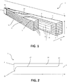
Figure 1 shows a perspective view of a CTC cable according to a possible embodiment; -
Figure 2 shows a schematic sectional view along a longitudinal development direction of the CTC cable according to a possible embodiment; -
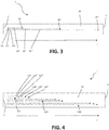
Figure 3 shows a schematic sectional view along a longitudinal development direction of the CTC cable according to a further possible embodiment; -
Figure 4 shows a schematic sectional view along a longitudinal development direction of the CTC cable according to a further possible embodiment; -
Figure 5 shows a schematic sectional view along a longitudinal development direction of the CTC cable according to a further possible embodiment. - The inventive concept will be described hereinafter with reference to the accompanying drawings, in which exemplifying embodiments are shown. The inventive concept may, however, be embodied in many different forms and should not be construed as limited to the embodiments set forth herein; rather, these embodiments are provided by way of example so that this disclosure will be thorough and complete, and will fully convey the scope of the inventive concept to those skilled in the art. Like numbers refer to like elements throughout the description.
- With reference to the annexed Figures, a continuously transposed cable (CTC) is indicated with
reference number 1. TheCTC cable 1 extends according to a longitudinal development direction L and comprises two oppositelongitudinal ends - The
CTC cable 1 comprises a plurality of single strands 4, each preferably in the form of a ribbon, i.e. having a transversal section substantially rectangular with a first dimension greater than the second dimension. Preferably, the strands 4 are externally at least in part electrically insulated, for example by one or more layers of electrical insulating enamel. - The strands 4 are arranged so to form a first 5 and a second 6 adjacent stacks, each extending along the longitudinal development direction L. Each
stack stack adjacent stacks CTC cable 1, i.e. each position along the overlapping direction I in each of thestacks CTC cable 1, which is perpendicular to a plane formed by the longitudinal development direction L and the overlapping direction I. - The stacks 5, 6 form a
longitudinal interface 16 therebetween. - Preferably, the strands 4 are held together by suitable connecting devices, such as, for example, one or more ribbons or
wires 14. According to a possible embodiment, the connecting devices are electrically insulating. Therefore, for example, the ribbons orwires 14 can be made of paper, or plastic, or other suitable electrically insulating material, such as nomex ®. In some applications, alternatively, theconnecting devices 14 do not perform the function of electrical isolation but only a mechanical function to hold the strands 4 together. - Preferably, the strands 4 are electrically connected in parallel at the
longitudinal ends CTC cable 1. - According to an embodiment, at the
interface 16 between the first 5 and the second 6 stacks theCTC cable 1 comprises aninsulating separator 7, which can extend in length along the longitudinal development direction L and in width along the overlapping direction I. The insulating separator is made of an electrically insulating material, such as for example paper, up-grade paper, pressboard, nomex ® or the like. Alternatively, theinsulating separator 7 can be missing. - The so formed
CTC cable 1 comprises, in addition to the already citedlongitudinal ends second side face 9, anupper face 10 and alower face 11. The first side face 8 is the external face of thefirst stack 5 opposite to theinterface 16 with thesecond stack 6. The second side face 8 is the external face of thesecond stack 6 opposite to theinterface 16 with thefirst stack 5. The upper 10 and lower 11 faces are the remaining faces of theCTC cable 1 and correspond respectively to the upper and lower portions of the couple of first 5 and second 6 adjacent stacks. - The
CTC cable 1 comprises one or moreoptical fibers 12 positioned at theinterface 16 between the first 5 and the second 6 stacks. - The
optical fibers 12 preferably extend parallel to the cable longitudinal development direction L. In accordance with an embodiment, theoptical fibers 12 are positioned on or inserted inside the insulating separator 7 (in this case theinsulating separator 7 can comprise for example two opposite portions and the optical fibers can be positioned therebetween. Alternatively, the insulating separator can comprise one or more tubular elements where the optical fibers can be inserted). This reduces the risk of damaging theoptical fibers 12, for example during the forming of a winding by theCTC cable 1 according to the invention. - According to a possible embodiment (as shown for example in
Figure 2 ), theoptical fibers 12 comprise afirst portion 15 outside theCTC cable 1, for example near the first 2 or the second 3 longitudinal end thereof, and asecond portion 17 extending inside theCTC cable 1 in correspondence of theinterface 16 between thestacks second portion 15 ends with atip 13, positioned inside thecable 1 in a specific position along theinterface 16, where the measurement by the optical fiber takes place. For example, thefirst portion 15 can be connected to a measuring apparatus (not shown in the Figures) suitable do detect a quantity, in particular the temperature, in correspondence of thetip 13 of the optical fiber. The principles underlying the measurement of the temperature at the tip of an optical fiber are known and will be not described here in detail. According to another embodiment, it is possible to measure the temperature along thesecond portion 17 up to thetip 13. Again, the principles underlying the measurement of the temperature along an optical fiber are known and will be not described here in detail. - The so configured CTC cable can be used for forming a windings of an electromagnetic induction device, such as a transformer. For example, the
free portion 15 can be positioned near the firstlongitudinal end 2, which in turn can correspond to the winding top exit. Preferably, thefree portion 15 does not exit the CTC cable exactly at thelongitudinal end tip 13 can be positioned in the most suitable intermediate position between the firstlongitudinal end 2 and the secondlongitudinal end 3, which in turn can correspond to the winding bottom exit. With this arrangement, it is possible to check the temperature in a specific position of the winding formed with theCTC cable 1. -
Figures 2-4 show further possible alternative embodiments of aCTC cable 1 usable for forming a transformer winding. In general, theCTC cable 1 can comprise a plurality ofoptical fibers 12 each having thetip 13 in a different position along the longitudinal development direction L and thefree portions 15 positioned near the first and/or the secondlongitudinal ends CTC cable 1 is used for forming a winding. - According to the embodiment shown in
Figure 3 , theCTC cable 1 comprises threeoptical fibers 12',12",12''', each having a respectivefree portion 15', 15", 15''' and atip 13', 13", 13'''. Thefree portions 15', 15", 15''', as mentioned above, are outside theCTC cable 1 and can be connected to a measurement device. Preferably, thefree portions 15', 15", 15'" are positioned near the top exit of the winding. Thetips 13', 13", 13''' can be respectively positioned near the first longitudinal end 2 (which in turn will correspond to the winding top exit), in an intermediate position (which in turn will correspond to a middle position of the winding), and near the second longitudinal end 3 (which in turn will correspond to the winding bottom exit). With this arrangement, it is possible to check the temperature in three different position of the winding, namely at the top exit, in the middle, and at the bottom exit. - With reference to the embodiment shown in
Figure 4 , theCTC cable 1 shown therein differs from the one shown inFigure 3 in that it comprises three groups 12I, 12II, 12III of optical fibers arranged similarly to the three singleoptical fibers 12', 12", 12''' of the embodiment inFigure 2 . Each group in turn comprises a plurality (three in the example shown) of optical fibers 12I', 12I", 12I''', ... having respective tips 13I', 13I", 13I'''; ... and free portions positioned near the firstlongitudinal end 2. - With reference to the embodiment shown in
Figure 5 , theCTC cable 1 still comprises three groups 12I, 12II, 12III of optical fibers each having respective tips 13I', 13I", 13I'''; ...arranged similarly to the three groups 12I, 12II, 12III with respective tips 13I', 13I", 13I'''; ...of optical fibers of the embodiment inFigure 4 . However, in this embodiment, the free portions of the optical fibers of the first and of the second groups are positioned near the firstlongitudinal end 2 of the CTC cable, whereas the free portions of the optical fibers of the third group are positioned near the secondlongitudinal end 3 of the CTC cable. Again, the first 2 and the second 3 longitudinal ends of theCTC cable 1 can respectively correspond to the winding top exit and to the winding bottom exit, or vice versa. In this manner, it is not necessary to use too long optical fibers. - It is to be noted that the
optical fibers 12 of theCTC cable 1 can be also used for obtaining a continuous temperature map along the cable (therefore, for example along the winding formed with the cable) instead of / in addition to the temperature at thetip 13. According to another option, it is possible to measure the distance of the point with maximum temperature from an end of the optical fiber, as well as the temperature in this point with maximum temperature. This allows the identification of the hot-spot in a winding formed with theCTC cable 1 according to the invention. This type of measurement can be obtained for example by using a particularly treated optical fiber known as Fiber Bragg Grating (FBG), or the like. Using optical fibers of this type or of similar types, in addition, allows the measurement of vibrations. - The FBG is a device that exploits the wavelength of light. It behaves essentially like a strain gauge and allows to realize sensors for localized measures of deformation (bending, traction, compression, torsion) and vibration. Taking advantage of the characteristics of the host material, in particular of elastomers, it is possible to measure weight, pressure and acceleration. Its characteristics also allow temperature measurements.
- From the above description, the skilled person will appreciate how the CTC cable according to the invention allows the construction of windings of devices, such as transformers, having an incorporated sensing device (particularly for sensing temperature and/or vibrations). Therefore, it is no longer necessary to apply the optical fibers to already formed windings. This results in a much easier and more reliable process for forming the winding.
- Furthermore, the CTC cable allows a flexible measurement, i.e. it is possible to determine multiple points or sketches where the quantity of interest is to be measured.
- To the above-mentioned embodiments of the CTC cable according to the invention, the skilled person, in order to meet specific current needs, can make several additions, modifications, or substitutions of elements with other operatively equivalent elements, without however departing from the scope of the appended claims.
Claims (15)
- Continuously transposed cable CTC (1) extending according to a longitudinal development direction (L) and having two opposite longitudinal ends (2, 3), said CTC cable (1) comprising a plurality of strands (4) arranged so to form at least a first (5) and a second (6) adjacent stacks, each extending along the longitudinal development direction (L), wherein said at least first (5) and second (6) stacks form a longitudinal interface (16) therebetween, characterized in that it further comprises one or more optical fibers (12) positioned at the interface (16) between the first (5) and the second (6) stacks.
- CTC cable (1) according to claim 1, wherein the one or more optical fibers (12) extend parallel to said longitudinal development direction (L).
- CTC cable (1) according to claim 1 or 2, comprising an insulating separator (7), made of electrically insulating material, at said interface (16) extending along the longitudinal development direction (L).
- CTC cable (1) according to claim 3, wherein the one or more optical fibers (12) are positioned on or inserted inside the insulating separator (7).
- CTC cable (1) according to claim 4, wherein the insulating separator (7) comprises two opposite portions and the one or more optical fibers are positioned therebetween, or wherein the insulating separator (7) comprises one or more tubular portions and the one or more optical fibers are positioned inside said one or more tubular portions.
- CTC cable (1) according to any of the preceding claims, wherein the one or more optical fibers (12) comprise a first portion (15) outside the CTC cable (1) at the first (2) and/or at the second (3) longitudinal end thereof, and a second portion (17) extending inside the CTC cable (1) in correspondence of said interface (16) between the first (5) and the second (6) stacks, wherein the second portion (15) of the one or more optical fibers (12) ends with a tip (13).
- CTC cable (1) according to any of the preceding claims, comprising a plurality of optical fibers (12) having a tip (13), wherein the tips (12) of each optical fiber is positioned in a different position along the longitudinal development direction (L).
- CTC cable (1) according to any of the preceding claims, wherein the CTC cable (1) comprises three optical fibers (12',12",12''') or three groups of optical fibers (12I, 12II, 12III) each comprising a plurality of optical fibers, each optical fiber of the three optical fibers or of the groups of optical fibers having a respective free portion (15', 15", 15''') outside the CTC cable (1) and a tip (13', 13", 13'''), respectively positioned near the first longitudinal end (2), in an intermediate position between the first (2) and the second (3) longitudinal end, and near the second longitudinal end (3).
- CTC cable (1) according to claim 8, wherein the tips of the plurality of optical fibers of each group are longitudinally shifted one relative to another.
- CTC cable (1) according to any of the preceding claims, comprising a measuring apparatus connected to the one or more optical fibers (12), said measuring apparatus being suitable to measure a quantity detected by the one or more optical fibers (12).
- CTC cable (1) according to claim 10, wherein said quantity includes: the temperature in correspondence of the tip (13), the temperature along the second portion (17) up to the tip (13), deformations and/or vibrations in correspondence of the tip (13).
- Winding of an electromagnetic induction device formed by winding a CTC cable (1) according to any of the preceding claims.
- Winding according to claim 12, having a winding top exit and a winding bottom exit, wherein one of the first (2) and the second (3) longitudinal end of the CTC cable (1) corresponds to the winding top exit and the other of the first (2) and the second (3) longitudinal end corresponds to the winding bottom exit.
- Electromagnetic induction device comprising one or more windings according to any of claims 12-13.
- Electromagnetic induction device according to claim 14, wherein the electromagnetic induction device is a transformer.
Priority Applications (6)
| Application Number | Priority Date | Filing Date | Title |
|---|---|---|---|
| EP18175054.8A EP3576106B1 (en) | 2018-05-30 | 2018-05-30 | Continuously transposed cable with an integrated sensing device |
| PCT/EP2019/061013 WO2019228733A1 (en) | 2018-05-30 | 2019-04-30 | Continuously transposed cable with an integrated sensing device |
| CA3111348A CA3111348C (en) | 2018-05-30 | 2019-04-30 | Continuously transposed cable with an integrated sensing device |
| CN201980033179.1A CN112166477B (en) | 2018-05-30 | 2019-04-30 | Continuously transposed cable, electromagnetic induction device and winding of electromagnetic induction device |
| US17/058,214 US12085453B2 (en) | 2018-05-30 | 2019-04-30 | Continuously transposed cable with an integrated sensing device |
| KR1020207034355A KR102682508B1 (en) | 2018-05-30 | 2019-04-30 | Continuous potential cable with integrated sensing device |
Applications Claiming Priority (1)
| Application Number | Priority Date | Filing Date | Title |
|---|---|---|---|
| EP18175054.8A EP3576106B1 (en) | 2018-05-30 | 2018-05-30 | Continuously transposed cable with an integrated sensing device |
Publications (2)
| Publication Number | Publication Date |
|---|---|
| EP3576106A1 true EP3576106A1 (en) | 2019-12-04 |
| EP3576106B1 EP3576106B1 (en) | 2021-03-03 |
Family
ID=62495588
Family Applications (1)
| Application Number | Title | Priority Date | Filing Date |
|---|---|---|---|
| EP18175054.8A Active EP3576106B1 (en) | 2018-05-30 | 2018-05-30 | Continuously transposed cable with an integrated sensing device |
Country Status (6)
| Country | Link |
|---|---|
| US (1) | US12085453B2 (en) |
| EP (1) | EP3576106B1 (en) |
| KR (1) | KR102682508B1 (en) |
| CN (1) | CN112166477B (en) |
| CA (1) | CA3111348C (en) |
| WO (1) | WO2019228733A1 (en) |
Cited By (1)
| Publication number | Priority date | Publication date | Assignee | Title |
|---|---|---|---|---|
| US11594361B1 (en) * | 2018-12-18 | 2023-02-28 | Smart Wires Inc. | Transformer having passive cooling topology |
Citations (7)
| Publication number | Priority date | Publication date | Assignee | Title |
|---|---|---|---|---|
| DE19507941A1 (en) * | 1994-03-10 | 1995-09-14 | Asta Elektrodraht Gmbh | Three core cord for electric machine and apparatus windings |
| JPH0880011A (en) * | 1994-09-06 | 1996-03-22 | Fuji Electric Co Ltd | Rotating electric machine winding temperature detector |
| US20050013342A1 (en) * | 2003-07-17 | 2005-01-20 | Kaminski Christopher Anthony | Measuring temperature in stationary components of electrical machines using fiber optics |
| US20050082084A1 (en) * | 2003-07-11 | 2005-04-21 | Oliver Drubel | Integrated arrangement of optical fibers in a conductor |
| CN201584206U (en) * | 2009-12-15 | 2010-09-15 | 无锡统力电工有限公司 | A Transposition Conductor with Inductive Function |
| US20140092938A1 (en) * | 2011-06-14 | 2014-04-03 | Siemens Aktiengesellschaft | Method for determining a temperature in a winding of subconductors of an electric machine |
| US20150235759A1 (en) * | 2012-10-10 | 2015-08-20 | Maschinenfabrik Reinhausen Gmbh | High voltage transformer having a sensor system, method for monitoring physical characteristic variables of a high voltage transformer and sensor system for monitoring physical characteristic variables |
Family Cites Families (7)
| Publication number | Priority date | Publication date | Assignee | Title |
|---|---|---|---|---|
| JP2000299967A (en) * | 1999-04-13 | 2000-10-24 | Fuji Electric Co Ltd | Rotating electric machine winding equipped with optical fiber sensor and method of attaching optical fiber sensor to rotating electric machine winding |
| DE19962668C1 (en) * | 1999-12-23 | 2000-12-07 | Siemens Ag | Optical measuring device for electrical apparatus such as generator or transformer |
| JP5614881B2 (en) * | 2010-08-19 | 2014-10-29 | 三菱日立パワーシステムズ株式会社 | Electrical equipment |
| CN202159514U (en) * | 2011-08-15 | 2012-03-07 | 沈阳市宏远电磁线有限公司 | Optical fiber transposed conductor |
| AU2014256932B2 (en) * | 2013-04-26 | 2017-01-05 | Wicor Holding Ag | Fiber-grating sensors having longitudinal-strain-inducing jackets and sensor systems and structures including such sensors |
| CN103425149A (en) * | 2013-06-28 | 2013-12-04 | 国网电力科学研究院武汉南瑞有限责任公司 | Transformer load control method based on utilizing fiber grating technology to measure hot spot temperature |
| EP3065150B1 (en) * | 2015-03-05 | 2017-11-29 | Siemens Aktiengesellschaft | Transformer |
-
2018
- 2018-05-30 EP EP18175054.8A patent/EP3576106B1/en active Active
-
2019
- 2019-04-30 KR KR1020207034355A patent/KR102682508B1/en active Active
- 2019-04-30 CN CN201980033179.1A patent/CN112166477B/en active Active
- 2019-04-30 CA CA3111348A patent/CA3111348C/en active Active
- 2019-04-30 WO PCT/EP2019/061013 patent/WO2019228733A1/en not_active Ceased
- 2019-04-30 US US17/058,214 patent/US12085453B2/en active Active
Patent Citations (7)
| Publication number | Priority date | Publication date | Assignee | Title |
|---|---|---|---|---|
| DE19507941A1 (en) * | 1994-03-10 | 1995-09-14 | Asta Elektrodraht Gmbh | Three core cord for electric machine and apparatus windings |
| JPH0880011A (en) * | 1994-09-06 | 1996-03-22 | Fuji Electric Co Ltd | Rotating electric machine winding temperature detector |
| US20050082084A1 (en) * | 2003-07-11 | 2005-04-21 | Oliver Drubel | Integrated arrangement of optical fibers in a conductor |
| US20050013342A1 (en) * | 2003-07-17 | 2005-01-20 | Kaminski Christopher Anthony | Measuring temperature in stationary components of electrical machines using fiber optics |
| CN201584206U (en) * | 2009-12-15 | 2010-09-15 | 无锡统力电工有限公司 | A Transposition Conductor with Inductive Function |
| US20140092938A1 (en) * | 2011-06-14 | 2014-04-03 | Siemens Aktiengesellschaft | Method for determining a temperature in a winding of subconductors of an electric machine |
| US20150235759A1 (en) * | 2012-10-10 | 2015-08-20 | Maschinenfabrik Reinhausen Gmbh | High voltage transformer having a sensor system, method for monitoring physical characteristic variables of a high voltage transformer and sensor system for monitoring physical characteristic variables |
Cited By (1)
| Publication number | Priority date | Publication date | Assignee | Title |
|---|---|---|---|---|
| US11594361B1 (en) * | 2018-12-18 | 2023-02-28 | Smart Wires Inc. | Transformer having passive cooling topology |
Also Published As
| Publication number | Publication date |
|---|---|
| CA3111348A1 (en) | 2019-12-05 |
| KR20210015822A (en) | 2021-02-10 |
| CN112166477A (en) | 2021-01-01 |
| CN112166477B (en) | 2022-08-16 |
| US12085453B2 (en) | 2024-09-10 |
| US20210190604A1 (en) | 2021-06-24 |
| EP3576106B1 (en) | 2021-03-03 |
| WO2019228733A1 (en) | 2019-12-05 |
| CA3111348C (en) | 2023-09-19 |
| KR102682508B1 (en) | 2024-07-05 |
Similar Documents
| Publication | Publication Date | Title |
|---|---|---|
| JP4588957B2 (en) | Optical measuring device for electrical equipment | |
| RU2510904C2 (en) | Electric cable with strain-gage and control system and method for strain detection in at least one electric cable | |
| EP3607333B1 (en) | Multi-phase sensor module and system | |
| JP2014524035A (en) | Fiber optic flux sensor for application to high voltage generator stator bars. | |
| US7469078B2 (en) | System for remote measurements | |
| CN103389176B (en) | A kind of Transformer Winding width is to stress measurement device and measuring method | |
| CN110197764B (en) | A kind of arrangement and protection method of distributed optical fiber inside transformer | |
| CN203337300U (en) | Transformer winding longitudinal stress measuring device | |
| CA3111348C (en) | Continuously transposed cable with an integrated sensing device | |
| US12188967B2 (en) | Photonic voltage transducer | |
| US7174075B2 (en) | Integrated arrangement of optical fibers in a conductor | |
| US10839984B2 (en) | Method and armoured cable for transporting high voltage alternate current | |
| US20140092938A1 (en) | Method for determining a temperature in a winding of subconductors of an electric machine | |
| CN103814321B (en) | Connectorized fiber optic cabling | |
| CN110520947B (en) | Static electric induction device comprising a winding and a sensor system for monitoring the temperature in the winding | |
| EP0917157A2 (en) | Insulator | |
| EP4411324A1 (en) | Multisensing cable for overhead power transmission lines | |
| JP2015203805A (en) | Optical cable connection part of electric power/optical composite cable | |
| US7339447B2 (en) | High-voltage transformer coil with acoustic wave guiding function | |
| BR102023021939A2 (en) | SEMI-DISTRIBUTED APPARATUS AND SYSTEM FOR DETECTING ELECTROMAGNETIC SIGNALS | |
| CN114608656A (en) | Transformer internal multi-physical-quantity state monitoring platform | |
| JPH03248102A (en) | Current detecting method for power line | |
| JPH02307345A (en) | Diagnosis of deterioration in insulation of coil and rotary electric machine |
Legal Events
| Date | Code | Title | Description |
|---|---|---|---|
| PUAI | Public reference made under article 153(3) epc to a published international application that has entered the european phase |
Free format text: ORIGINAL CODE: 0009012 |
|
| STAA | Information on the status of an ep patent application or granted ep patent |
Free format text: STATUS: THE APPLICATION HAS BEEN PUBLISHED |
|
| AK | Designated contracting states |
Kind code of ref document: A1 Designated state(s): AL AT BE BG CH CY CZ DE DK EE ES FI FR GB GR HR HU IE IS IT LI LT LU LV MC MK MT NL NO PL PT RO RS SE SI SK SM TR |
|
| AX | Request for extension of the european patent |
Extension state: BA ME |
|
| STAA | Information on the status of an ep patent application or granted ep patent |
Free format text: STATUS: REQUEST FOR EXAMINATION WAS MADE |
|
| STAA | Information on the status of an ep patent application or granted ep patent |
Free format text: STATUS: EXAMINATION IS IN PROGRESS |
|
| 17P | Request for examination filed |
Effective date: 20200305 |
|
| RBV | Designated contracting states (corrected) |
Designated state(s): AL AT BE BG CH CY CZ DE DK EE ES FI FR GB GR HR HU IE IS IT LI LT LU LV MC MK MT NL NO PL PT RO RS SE SI SK SM TR |
|
| 17Q | First examination report despatched |
Effective date: 20200402 |
|
| RAP1 | Party data changed (applicant data changed or rights of an application transferred) |
Owner name: ABB SCHWEIZ AG |
|
| RAP1 | Party data changed (applicant data changed or rights of an application transferred) |
Owner name: ABB POWER GRIDS SWITZERLAND AG |
|
| GRAP | Despatch of communication of intention to grant a patent |
Free format text: ORIGINAL CODE: EPIDOSNIGR1 |
|
| STAA | Information on the status of an ep patent application or granted ep patent |
Free format text: STATUS: GRANT OF PATENT IS INTENDED |
|
| RIC1 | Information provided on ipc code assigned before grant |
Ipc: G01K 11/32 20060101ALN20200724BHEP Ipc: H01B 7/32 20060101ALI20200724BHEP Ipc: H01B 7/30 20060101AFI20200724BHEP Ipc: H01F 27/28 20060101ALN20200724BHEP Ipc: H02K 3/14 20060101ALI20200724BHEP Ipc: H01F 27/40 20060101ALI20200724BHEP Ipc: H02K 11/25 20160101ALI20200724BHEP Ipc: H02K 11/21 20160101ALI20200724BHEP |
|
| INTG | Intention to grant announced |
Effective date: 20200820 |
|
| GRAS | Grant fee paid |
Free format text: ORIGINAL CODE: EPIDOSNIGR3 |
|
| RIN1 | Information on inventor provided before grant (corrected) |
Inventor name: PAVANELLO, PAOLO Inventor name: BUSTREO, GIANLUCA Inventor name: ZANNOL, ROBERTO |
|
| GRAA | (expected) grant |
Free format text: ORIGINAL CODE: 0009210 |
|
| STAA | Information on the status of an ep patent application or granted ep patent |
Free format text: STATUS: THE PATENT HAS BEEN GRANTED |
|
| AK | Designated contracting states |
Kind code of ref document: B1 Designated state(s): AL AT BE BG CH CY CZ DE DK EE ES FI FR GB GR HR HU IE IS IT LI LT LU LV MC MK MT NL NO PL PT RO RS SE SI SK SM TR |
|
| REG | Reference to a national code |
Ref country code: GB Ref legal event code: FG4D |
|
| REG | Reference to a national code |
Ref country code: AT Ref legal event code: REF Ref document number: 1368102 Country of ref document: AT Kind code of ref document: T Effective date: 20210315 Ref country code: CH Ref legal event code: EP |
|
| REG | Reference to a national code |
Ref country code: DE Ref legal event code: R096 Ref document number: 602018013248 Country of ref document: DE |
|
| REG | Reference to a national code |
Ref country code: IE Ref legal event code: FG4D |
|
| REG | Reference to a national code |
Ref country code: LT Ref legal event code: MG9D |
|
| PG25 | Lapsed in a contracting state [announced via postgrant information from national office to epo] |
Ref country code: BG Free format text: LAPSE BECAUSE OF FAILURE TO SUBMIT A TRANSLATION OF THE DESCRIPTION OR TO PAY THE FEE WITHIN THE PRESCRIBED TIME-LIMIT Effective date: 20210603 Ref country code: GR Free format text: LAPSE BECAUSE OF FAILURE TO SUBMIT A TRANSLATION OF THE DESCRIPTION OR TO PAY THE FEE WITHIN THE PRESCRIBED TIME-LIMIT Effective date: 20210604 Ref country code: HR Free format text: LAPSE BECAUSE OF FAILURE TO SUBMIT A TRANSLATION OF THE DESCRIPTION OR TO PAY THE FEE WITHIN THE PRESCRIBED TIME-LIMIT Effective date: 20210303 Ref country code: FI Free format text: LAPSE BECAUSE OF FAILURE TO SUBMIT A TRANSLATION OF THE DESCRIPTION OR TO PAY THE FEE WITHIN THE PRESCRIBED TIME-LIMIT Effective date: 20210303 Ref country code: LT Free format text: LAPSE BECAUSE OF FAILURE TO SUBMIT A TRANSLATION OF THE DESCRIPTION OR TO PAY THE FEE WITHIN THE PRESCRIBED TIME-LIMIT Effective date: 20210303 Ref country code: NO Free format text: LAPSE BECAUSE OF FAILURE TO SUBMIT A TRANSLATION OF THE DESCRIPTION OR TO PAY THE FEE WITHIN THE PRESCRIBED TIME-LIMIT Effective date: 20210603 |
|
| REG | Reference to a national code |
Ref country code: NL Ref legal event code: MP Effective date: 20210303 |
|
| REG | Reference to a national code |
Ref country code: AT Ref legal event code: MK05 Ref document number: 1368102 Country of ref document: AT Kind code of ref document: T Effective date: 20210303 |
|
| PG25 | Lapsed in a contracting state [announced via postgrant information from national office to epo] |
Ref country code: SE Free format text: LAPSE BECAUSE OF FAILURE TO SUBMIT A TRANSLATION OF THE DESCRIPTION OR TO PAY THE FEE WITHIN THE PRESCRIBED TIME-LIMIT Effective date: 20210303 Ref country code: RS Free format text: LAPSE BECAUSE OF FAILURE TO SUBMIT A TRANSLATION OF THE DESCRIPTION OR TO PAY THE FEE WITHIN THE PRESCRIBED TIME-LIMIT Effective date: 20210303 Ref country code: PL Free format text: LAPSE BECAUSE OF FAILURE TO SUBMIT A TRANSLATION OF THE DESCRIPTION OR TO PAY THE FEE WITHIN THE PRESCRIBED TIME-LIMIT Effective date: 20210303 Ref country code: LV Free format text: LAPSE BECAUSE OF FAILURE TO SUBMIT A TRANSLATION OF THE DESCRIPTION OR TO PAY THE FEE WITHIN THE PRESCRIBED TIME-LIMIT Effective date: 20210303 |
|
| PG25 | Lapsed in a contracting state [announced via postgrant information from national office to epo] |
Ref country code: NL Free format text: LAPSE BECAUSE OF FAILURE TO SUBMIT A TRANSLATION OF THE DESCRIPTION OR TO PAY THE FEE WITHIN THE PRESCRIBED TIME-LIMIT Effective date: 20210303 |
|
| PG25 | Lapsed in a contracting state [announced via postgrant information from national office to epo] |
Ref country code: EE Free format text: LAPSE BECAUSE OF FAILURE TO SUBMIT A TRANSLATION OF THE DESCRIPTION OR TO PAY THE FEE WITHIN THE PRESCRIBED TIME-LIMIT Effective date: 20210303 Ref country code: CZ Free format text: LAPSE BECAUSE OF FAILURE TO SUBMIT A TRANSLATION OF THE DESCRIPTION OR TO PAY THE FEE WITHIN THE PRESCRIBED TIME-LIMIT Effective date: 20210303 Ref country code: SM Free format text: LAPSE BECAUSE OF FAILURE TO SUBMIT A TRANSLATION OF THE DESCRIPTION OR TO PAY THE FEE WITHIN THE PRESCRIBED TIME-LIMIT Effective date: 20210303 Ref country code: AT Free format text: LAPSE BECAUSE OF FAILURE TO SUBMIT A TRANSLATION OF THE DESCRIPTION OR TO PAY THE FEE WITHIN THE PRESCRIBED TIME-LIMIT Effective date: 20210303 |
|
| PG25 | Lapsed in a contracting state [announced via postgrant information from national office to epo] |
Ref country code: IS Free format text: LAPSE BECAUSE OF FAILURE TO SUBMIT A TRANSLATION OF THE DESCRIPTION OR TO PAY THE FEE WITHIN THE PRESCRIBED TIME-LIMIT Effective date: 20210703 Ref country code: RO Free format text: LAPSE BECAUSE OF FAILURE TO SUBMIT A TRANSLATION OF THE DESCRIPTION OR TO PAY THE FEE WITHIN THE PRESCRIBED TIME-LIMIT Effective date: 20210303 Ref country code: SK Free format text: LAPSE BECAUSE OF FAILURE TO SUBMIT A TRANSLATION OF THE DESCRIPTION OR TO PAY THE FEE WITHIN THE PRESCRIBED TIME-LIMIT Effective date: 20210303 Ref country code: PT Free format text: LAPSE BECAUSE OF FAILURE TO SUBMIT A TRANSLATION OF THE DESCRIPTION OR TO PAY THE FEE WITHIN THE PRESCRIBED TIME-LIMIT Effective date: 20210705 |
|
| REG | Reference to a national code |
Ref country code: DE Ref legal event code: R097 Ref document number: 602018013248 Country of ref document: DE |
|
| REG | Reference to a national code |
Ref country code: CH Ref legal event code: PL |
|
| PLBE | No opposition filed within time limit |
Free format text: ORIGINAL CODE: 0009261 |
|
| STAA | Information on the status of an ep patent application or granted ep patent |
Free format text: STATUS: NO OPPOSITION FILED WITHIN TIME LIMIT |
|
| RAP4 | Party data changed (patent owner data changed or rights of a patent transferred) |
Owner name: HITACHI ENERGY SWITZERLAND AG |
|
| PG25 | Lapsed in a contracting state [announced via postgrant information from national office to epo] |
Ref country code: CH Free format text: LAPSE BECAUSE OF NON-PAYMENT OF DUE FEES Effective date: 20210531 Ref country code: DK Free format text: LAPSE BECAUSE OF FAILURE TO SUBMIT A TRANSLATION OF THE DESCRIPTION OR TO PAY THE FEE WITHIN THE PRESCRIBED TIME-LIMIT Effective date: 20210303 Ref country code: AL Free format text: LAPSE BECAUSE OF FAILURE TO SUBMIT A TRANSLATION OF THE DESCRIPTION OR TO PAY THE FEE WITHIN THE PRESCRIBED TIME-LIMIT Effective date: 20210303 Ref country code: LI Free format text: LAPSE BECAUSE OF NON-PAYMENT OF DUE FEES Effective date: 20210531 Ref country code: LU Free format text: LAPSE BECAUSE OF NON-PAYMENT OF DUE FEES Effective date: 20210530 Ref country code: MC Free format text: LAPSE BECAUSE OF FAILURE TO SUBMIT A TRANSLATION OF THE DESCRIPTION OR TO PAY THE FEE WITHIN THE PRESCRIBED TIME-LIMIT Effective date: 20210303 Ref country code: ES Free format text: LAPSE BECAUSE OF FAILURE TO SUBMIT A TRANSLATION OF THE DESCRIPTION OR TO PAY THE FEE WITHIN THE PRESCRIBED TIME-LIMIT Effective date: 20210303 |
|
| 26N | No opposition filed |
Effective date: 20211206 |
|
| REG | Reference to a national code |
Ref country code: BE Ref legal event code: MM Effective date: 20210531 |
|
| PG25 | Lapsed in a contracting state [announced via postgrant information from national office to epo] |
Ref country code: SI Free format text: LAPSE BECAUSE OF FAILURE TO SUBMIT A TRANSLATION OF THE DESCRIPTION OR TO PAY THE FEE WITHIN THE PRESCRIBED TIME-LIMIT Effective date: 20210303 |
|
| PG25 | Lapsed in a contracting state [announced via postgrant information from national office to epo] |
Ref country code: IE Free format text: LAPSE BECAUSE OF NON-PAYMENT OF DUE FEES Effective date: 20210530 |
|
| PG25 | Lapsed in a contracting state [announced via postgrant information from national office to epo] |
Ref country code: IS Free format text: LAPSE BECAUSE OF FAILURE TO SUBMIT A TRANSLATION OF THE DESCRIPTION OR TO PAY THE FEE WITHIN THE PRESCRIBED TIME-LIMIT Effective date: 20210703 |
|
| REG | Reference to a national code |
Ref country code: DE Ref legal event code: R081 Ref document number: 602018013248 Country of ref document: DE Owner name: HITACHI ENERGY SWITZERLAND AG, CH Free format text: FORMER OWNER: ABB POWER GRIDS SWITZERLAND AG, BADEN, CH Ref country code: DE Ref legal event code: R081 Ref document number: 602018013248 Country of ref document: DE Owner name: HITACHI ENERGY LTD, CH Free format text: FORMER OWNER: ABB POWER GRIDS SWITZERLAND AG, BADEN, CH |
|
| PG25 | Lapsed in a contracting state [announced via postgrant information from national office to epo] |
Ref country code: BE Free format text: LAPSE BECAUSE OF NON-PAYMENT OF DUE FEES Effective date: 20210531 |
|
| PG25 | Lapsed in a contracting state [announced via postgrant information from national office to epo] |
Ref country code: CY Free format text: LAPSE BECAUSE OF FAILURE TO SUBMIT A TRANSLATION OF THE DESCRIPTION OR TO PAY THE FEE WITHIN THE PRESCRIBED TIME-LIMIT Effective date: 20210303 |
|
| P01 | Opt-out of the competence of the unified patent court (upc) registered |
Effective date: 20230527 |
|
| PG25 | Lapsed in a contracting state [announced via postgrant information from national office to epo] |
Ref country code: HU Free format text: LAPSE BECAUSE OF FAILURE TO SUBMIT A TRANSLATION OF THE DESCRIPTION OR TO PAY THE FEE WITHIN THE PRESCRIBED TIME-LIMIT; INVALID AB INITIO Effective date: 20180530 |
|
| REG | Reference to a national code |
Ref country code: DE Ref legal event code: R082 Ref document number: 602018013248 Country of ref document: DE Representative=s name: DENNEMEYER & ASSOCIATES RECHTSANWALTSGESELLSCH, DE Ref country code: DE Ref legal event code: R082 Ref document number: 602018013248 Country of ref document: DE Representative=s name: DENNEMEYER & ASSOCIATES S.A., DE Ref country code: DE Ref legal event code: R081 Ref document number: 602018013248 Country of ref document: DE Owner name: HITACHI ENERGY LTD, CH Free format text: FORMER OWNER: HITACHI ENERGY SWITZERLAND AG, BADEN, CH |
|
| PG25 | Lapsed in a contracting state [announced via postgrant information from national office to epo] |
Ref country code: MK Free format text: LAPSE BECAUSE OF FAILURE TO SUBMIT A TRANSLATION OF THE DESCRIPTION OR TO PAY THE FEE WITHIN THE PRESCRIBED TIME-LIMIT Effective date: 20210303 |
|
| PG25 | Lapsed in a contracting state [announced via postgrant information from national office to epo] |
Ref country code: TR Free format text: LAPSE BECAUSE OF FAILURE TO SUBMIT A TRANSLATION OF THE DESCRIPTION OR TO PAY THE FEE WITHIN THE PRESCRIBED TIME-LIMIT Effective date: 20210303 |
|
| REG | Reference to a national code |
Ref country code: GB Ref legal event code: 732E Free format text: REGISTERED BETWEEN 20240718 AND 20240724 |
|
| PG25 | Lapsed in a contracting state [announced via postgrant information from national office to epo] |
Ref country code: MT Free format text: LAPSE BECAUSE OF FAILURE TO SUBMIT A TRANSLATION OF THE DESCRIPTION OR TO PAY THE FEE WITHIN THE PRESCRIBED TIME-LIMIT Effective date: 20210303 |
|
| REG | Reference to a national code |
Ref country code: DE Ref legal event code: R082 Ref document number: 602018013248 Country of ref document: DE Representative=s name: DENNEMEYER & ASSOCIATES RECHTSANWALTSGESELLSCH, DE |
|
| PGFP | Annual fee paid to national office [announced via postgrant information from national office to epo] |
Ref country code: DE Payment date: 20250521 Year of fee payment: 8 |
|
| PGFP | Annual fee paid to national office [announced via postgrant information from national office to epo] |
Ref country code: GB Payment date: 20250527 Year of fee payment: 8 |
|
| PGFP | Annual fee paid to national office [announced via postgrant information from national office to epo] |
Ref country code: IT Payment date: 20250527 Year of fee payment: 8 |
|
| PGFP | Annual fee paid to national office [announced via postgrant information from national office to epo] |
Ref country code: FR Payment date: 20250528 Year of fee payment: 8 |