EP3576105A1 - Electricity-supplying cable, and connector-equipped electricity-supplying cable - Google Patents
Electricity-supplying cable, and connector-equipped electricity-supplying cable Download PDFInfo
- Publication number
- EP3576105A1 EP3576105A1 EP18744254.6A EP18744254A EP3576105A1 EP 3576105 A1 EP3576105 A1 EP 3576105A1 EP 18744254 A EP18744254 A EP 18744254A EP 3576105 A1 EP3576105 A1 EP 3576105A1
- Authority
- EP
- European Patent Office
- Prior art keywords
- power supply
- communication
- communication cord
- supply cable
- power
- Prior art date
- Legal status (The legal status is an assumption and is not a legal conclusion. Google has not performed a legal analysis and makes no representation as to the accuracy of the status listed.)
- Withdrawn
Links
Images
Classifications
-
- B—PERFORMING OPERATIONS; TRANSPORTING
- B60—VEHICLES IN GENERAL
- B60L—PROPULSION OF ELECTRICALLY-PROPELLED VEHICLES; SUPPLYING ELECTRIC POWER FOR AUXILIARY EQUIPMENT OF ELECTRICALLY-PROPELLED VEHICLES; ELECTRODYNAMIC BRAKE SYSTEMS FOR VEHICLES IN GENERAL; MAGNETIC SUSPENSION OR LEVITATION FOR VEHICLES; MONITORING OPERATING VARIABLES OF ELECTRICALLY-PROPELLED VEHICLES; ELECTRIC SAFETY DEVICES FOR ELECTRICALLY-PROPELLED VEHICLES
- B60L53/00—Methods of charging batteries, specially adapted for electric vehicles; Charging stations or on-board charging equipment therefor; Exchange of energy storage elements in electric vehicles
- B60L53/30—Constructional details of charging stations
- B60L53/302—Cooling of charging equipment
-
- H—ELECTRICITY
- H01—ELECTRIC ELEMENTS
- H01B—CABLES; CONDUCTORS; INSULATORS; SELECTION OF MATERIALS FOR THEIR CONDUCTIVE, INSULATING OR DIELECTRIC PROPERTIES
- H01B7/00—Insulated conductors or cables characterised by their form
-
- H—ELECTRICITY
- H01—ELECTRIC ELEMENTS
- H01B—CABLES; CONDUCTORS; INSULATORS; SELECTION OF MATERIALS FOR THEIR CONDUCTIVE, INSULATING OR DIELECTRIC PROPERTIES
- H01B7/00—Insulated conductors or cables characterised by their form
- H01B7/17—Protection against damage caused by external factors, e.g. sheaths or armouring
- H01B7/18—Protection against damage caused by wear, mechanical force or pressure; Sheaths; Armouring
-
- H—ELECTRICITY
- H01—ELECTRIC ELEMENTS
- H01B—CABLES; CONDUCTORS; INSULATORS; SELECTION OF MATERIALS FOR THEIR CONDUCTIVE, INSULATING OR DIELECTRIC PROPERTIES
- H01B7/00—Insulated conductors or cables characterised by their form
- H01B7/42—Insulated conductors or cables characterised by their form with arrangements for heat dissipation or conduction
- H01B7/421—Insulated conductors or cables characterised by their form with arrangements for heat dissipation or conduction for heat dissipation
- H01B7/423—Insulated conductors or cables characterised by their form with arrangements for heat dissipation or conduction for heat dissipation using a cooling fluid
- H01B7/425—Insulated conductors or cables characterised by their form with arrangements for heat dissipation or conduction for heat dissipation using a cooling fluid the construction being bendable
-
- H—ELECTRICITY
- H01—ELECTRIC ELEMENTS
- H01B—CABLES; CONDUCTORS; INSULATORS; SELECTION OF MATERIALS FOR THEIR CONDUCTIVE, INSULATING OR DIELECTRIC PROPERTIES
- H01B9/00—Power cables
- H01B9/003—Power cables including electrical control or communication wires
-
- H—ELECTRICITY
- H01—ELECTRIC ELEMENTS
- H01R—ELECTRICALLY-CONDUCTIVE CONNECTIONS; STRUCTURAL ASSOCIATIONS OF A PLURALITY OF MUTUALLY-INSULATED ELECTRICAL CONNECTING ELEMENTS; COUPLING DEVICES; CURRENT COLLECTORS
- H01R13/00—Details of coupling devices of the kinds covered by groups H01R12/70 or H01R24/00 - H01R33/00
- H01R13/46—Bases; Cases
-
- B—PERFORMING OPERATIONS; TRANSPORTING
- B60—VEHICLES IN GENERAL
- B60L—PROPULSION OF ELECTRICALLY-PROPELLED VEHICLES; SUPPLYING ELECTRIC POWER FOR AUXILIARY EQUIPMENT OF ELECTRICALLY-PROPELLED VEHICLES; ELECTRODYNAMIC BRAKE SYSTEMS FOR VEHICLES IN GENERAL; MAGNETIC SUSPENSION OR LEVITATION FOR VEHICLES; MONITORING OPERATING VARIABLES OF ELECTRICALLY-PROPELLED VEHICLES; ELECTRIC SAFETY DEVICES FOR ELECTRICALLY-PROPELLED VEHICLES
- B60L53/00—Methods of charging batteries, specially adapted for electric vehicles; Charging stations or on-board charging equipment therefor; Exchange of energy storage elements in electric vehicles
- B60L53/10—Methods of charging batteries, specially adapted for electric vehicles; Charging stations or on-board charging equipment therefor; Exchange of energy storage elements in electric vehicles characterised by the energy transfer between the charging station and the vehicle
- B60L53/14—Conductive energy transfer
- B60L53/18—Cables specially adapted for charging electric vehicles
-
- Y—GENERAL TAGGING OF NEW TECHNOLOGICAL DEVELOPMENTS; GENERAL TAGGING OF CROSS-SECTIONAL TECHNOLOGIES SPANNING OVER SEVERAL SECTIONS OF THE IPC; TECHNICAL SUBJECTS COVERED BY FORMER USPC CROSS-REFERENCE ART COLLECTIONS [XRACs] AND DIGESTS
- Y02—TECHNOLOGIES OR APPLICATIONS FOR MITIGATION OR ADAPTATION AGAINST CLIMATE CHANGE
- Y02T—CLIMATE CHANGE MITIGATION TECHNOLOGIES RELATED TO TRANSPORTATION
- Y02T10/00—Road transport of goods or passengers
- Y02T10/60—Other road transportation technologies with climate change mitigation effect
- Y02T10/70—Energy storage systems for electromobility, e.g. batteries
-
- Y—GENERAL TAGGING OF NEW TECHNOLOGICAL DEVELOPMENTS; GENERAL TAGGING OF CROSS-SECTIONAL TECHNOLOGIES SPANNING OVER SEVERAL SECTIONS OF THE IPC; TECHNICAL SUBJECTS COVERED BY FORMER USPC CROSS-REFERENCE ART COLLECTIONS [XRACs] AND DIGESTS
- Y02—TECHNOLOGIES OR APPLICATIONS FOR MITIGATION OR ADAPTATION AGAINST CLIMATE CHANGE
- Y02T—CLIMATE CHANGE MITIGATION TECHNOLOGIES RELATED TO TRANSPORTATION
- Y02T10/00—Road transport of goods or passengers
- Y02T10/60—Other road transportation technologies with climate change mitigation effect
- Y02T10/7072—Electromobility specific charging systems or methods for batteries, ultracapacitors, supercapacitors or double-layer capacitors
-
- Y—GENERAL TAGGING OF NEW TECHNOLOGICAL DEVELOPMENTS; GENERAL TAGGING OF CROSS-SECTIONAL TECHNOLOGIES SPANNING OVER SEVERAL SECTIONS OF THE IPC; TECHNICAL SUBJECTS COVERED BY FORMER USPC CROSS-REFERENCE ART COLLECTIONS [XRACs] AND DIGESTS
- Y02—TECHNOLOGIES OR APPLICATIONS FOR MITIGATION OR ADAPTATION AGAINST CLIMATE CHANGE
- Y02T—CLIMATE CHANGE MITIGATION TECHNOLOGIES RELATED TO TRANSPORTATION
- Y02T90/00—Enabling technologies or technologies with a potential or indirect contribution to GHG emissions mitigation
- Y02T90/10—Technologies relating to charging of electric vehicles
- Y02T90/12—Electric charging stations
-
- Y—GENERAL TAGGING OF NEW TECHNOLOGICAL DEVELOPMENTS; GENERAL TAGGING OF CROSS-SECTIONAL TECHNOLOGIES SPANNING OVER SEVERAL SECTIONS OF THE IPC; TECHNICAL SUBJECTS COVERED BY FORMER USPC CROSS-REFERENCE ART COLLECTIONS [XRACs] AND DIGESTS
- Y02—TECHNOLOGIES OR APPLICATIONS FOR MITIGATION OR ADAPTATION AGAINST CLIMATE CHANGE
- Y02T—CLIMATE CHANGE MITIGATION TECHNOLOGIES RELATED TO TRANSPORTATION
- Y02T90/00—Enabling technologies or technologies with a potential or indirect contribution to GHG emissions mitigation
- Y02T90/10—Technologies relating to charging of electric vehicles
- Y02T90/14—Plug-in electric vehicles
-
- Y—GENERAL TAGGING OF NEW TECHNOLOGICAL DEVELOPMENTS; GENERAL TAGGING OF CROSS-SECTIONAL TECHNOLOGIES SPANNING OVER SEVERAL SECTIONS OF THE IPC; TECHNICAL SUBJECTS COVERED BY FORMER USPC CROSS-REFERENCE ART COLLECTIONS [XRACs] AND DIGESTS
- Y02—TECHNOLOGIES OR APPLICATIONS FOR MITIGATION OR ADAPTATION AGAINST CLIMATE CHANGE
- Y02T—CLIMATE CHANGE MITIGATION TECHNOLOGIES RELATED TO TRANSPORTATION
- Y02T90/00—Enabling technologies or technologies with a potential or indirect contribution to GHG emissions mitigation
- Y02T90/10—Technologies relating to charging of electric vehicles
- Y02T90/16—Information or communication technologies improving the operation of electric vehicles
Definitions
- the present invention relates to a power supply cable and a power supply cable with a connector.
- the power supply cable includes a plurality of power lines, and a sheath covering the power lines.
- Each power line includes a tubular conductor which is a flow path of a refrigerant, and an insulator surrounding the conductor.
- a signal line used for communication with a power supply target or the like may be accommodated in the sheath together with the power lines.
- the positions of the signal line and the power line in the sheath may change during use over a long period of time, and the durability against the bending of the power supply cable may be degraded.
- the present invention has been made in consideration of such circumstances, and an object of the present invention is to provide a power supply cable and a power supply cable with a connector, in which positions of a signal line and a power line in a sheath are hardly changed and durability against bending is maintained.
- a power supply cable includes a first communication cord having a first signal line and a cover accommodating therein the first signal line; a plurality of power lines each having a cooling tube, a conductor surrounding the cooling tube, and an insulator surrounding the conductor; and a sheath accommodating therein the first communication cord and the plurality of power lines, in which In the cross-sectional view, the plurality of power lines are disposed so as to surround the first communication cord.
- each power line since each power line has the cooling tube and the conductor surrounding the cooling tube, the conductor in the power line is cooled by the cooling tube from the inside thereof.
- the inside of the power line as the heat source is evenly cooled, occurrence of uneven temperature in the power supply cable and the sheath surface can be suppressed, and the conductor can be efficiently cooled.
- the plurality of power lines are disposed so as to surround the first communication cord, and the first communication cord has a cover accommodating the first signal lines therein.
- the thickness of the cover of the first communication cord can be appropriately adjusted.
- by changing the outer diameter of the first communication cord it is possible to easily adjust the radial position of each power line surrounding the first communication cord in the sheath.
- each power line is in contact with the first communication cord in the radial direction and is in contact with another power line adjacent in the circumferential direction, so the position of each member in the sheath is hardly changed and durability against bending of the power supply cable can be maintained.
- the first communication cord may include a plurality of the first signal lines, and the plurality of first signal lines may be accommodated in the cover in a state of being wound integrally with the tape.
- the plurality of first signal lines are integrally wound with the tape, for example, when extruding the cover, it is possible to prevent the softened material to be the cover from entering between the first signal lines.
- the thickness of the cover and the outer diameter of the first communication cord thereby the above-described effect could be more reliably achieved.
- a second communication cord having a second signal line and the plurality of power lines may be disposed so as to surround the first communication cord in the cross-sectional view.
- the number of provided communication means in the power supply cable can be increased due to the second communication cords. Further, since the second communication cord and each power line are disposed so as to surround the first communication cord, as described above, the position of each member in the sheath is hardly changed and durability against bending of the power supply cable is maintained.
- the number of second communication cords may be two, and the number of the plurality of power lines may be four, and the first communication cord, the two second communication cords, and the four power lines may have substantially the same outer diameters.
- a total of six second communication cords and power lines are disposed so as to surround the first communication cord having substantially the same outer diameter.
- each member are stabilized in a state where the power line and the second communication cord are wound around the first communication cord. This makes it difficult for the state to collapse, and it is also possible to simplify and stabilize the manufacturing process when these members are accommodated in the sheath.
- the power supply cable of the above aspect may include a second communication cord having a plurality of second signal lines, the first communication cord has a plurality of the first signal lines, and the number of the first signal lines of the first communication cord may be smaller than the number of the second signal lines of the second communication cord.
- the adjustment range of the thickness of the cover accommodating the first signal lines therein can be increased. This makes it possible to more easily stabilize the position of each member in the sheath, with the first communication cord as the desired outer diameter, as described above.
- the plurality of first signal lines may be accommodated in the cover in a twisted state, and may be used for communication with a power supply target.
- the adjustment range of the pitch for twisting the first signal lines can be increased. This makes it possible to easily select an optimum twist pitch such that the influence of noise acting on the first signal line is reduced. Further, by using the first signal line for communication with the power supply target, it is possible to provide a power supply cable ensuring reliability of communication with the power supply target.
- a power supply cable with a connector includes the power supply cable, and a connector configured to be connected to a power supply target.
- the power supply cable with a connector of the above aspect it is possible to stably dispose each member in the sheath while suppressing the occurrence of unevenness in temperature on the surface of the sheath at the time of power supplying.
- a power supply cable 1 includes a plurality of power lines 10, a first communication cord 20, a plurality of second communication cords 30, a filling 2, and a sheath 4.
- the power supply cable 1 includes four power lines 10 and two second communication cords 30. Even number of power lines 10 and second communication cords 30 are provided.
- the power supply cable 1 is used, for example, when electrically connecting the charger and the power supply target object and supplying power to the power supply target.
- the power supply target may be an electric vehicle (vehicle) or the like.
- the power supply cable 1 may be accommodated by being partially wound when not in use. When used, the power supply cable 1 is pulled out from the partially wound accommodated state. That is, winding and pulling out of the power supply cable 1 may be repeated. Therefore, durability against friction, durability against bending, flexibility, and the like are required for the entire power supply cable 1.
- a direction along the central axis O of the power supply cable 1 is referred to as a longitudinal direction.
- a direction orthogonal to the central axis O is referred to as a radial direction, and a direction revolving around the central axis O is referred to as a circumferential direction.
- the first communication cord 20 may be used for communication between, for example, a vehicle as a power supply target and a charger.
- the first communication cord 20 is disposed at the center of the power supply cable 1.
- the first communication cord 20 is surrounded by four power lines 10 and two second communication cords 30.
- the first communication cord 20 includes a plurality (two) of first signal lines 21, a tape 22 that wraps around the first signal lines 21, and a cover 23 covering the tape 22.
- the number of the first signal lines 21 included in the first communication cord 20 is smaller than the number of the second signal lines 31 included in the second communication cord 30.
- the number of first signal lines 21 is two and the number of second signal lines 31 is six.
- the first communication cord 20 has flexibility.
- the first signal line 21 has a configuration in which the conductor 21a is covered with an insulator 21b.
- the plurality of first signal lines 21 are accommodated in the cover 23 in a state of being integrally wound with the tape 22.
- the two first signal lines 21 are accommodated in the cover 23 in a twisted state.
- One first communication cord 20 is a so-called twisted pair cable. Therefore, the adjustment range of the pitch for twisting the two first signal lines 21 can be increased, and an optimum pitch can be selected from the viewpoint of noise during communication.
- the thickness of the cover 23 is larger than the thickness of the tape 22.
- the thickness of the cover 23 is larger than the thickness of the tape 32 to be described later of the second communication cord 30.
- the second communication cord 30 is disposed radially outward of the first communication cord 20.
- two second communication cords 30 are disposed so as to sandwich the first communication cord 20 in the radial direction.
- the outer diameter of the second communication cord 30 is substantially the same as the outer diameters of the first communication cord 20 and the power line 10.
- the outer diameters of the two second communication cords 30 are substantially the same as each other.
- the second communication cord 30 has flexibility.
- the second communication cord 30 includes six second signal lines 31, and a tape 32 that wraps around the second signal lines 31.
- Each second signal line 31 is used for controlling the locking mechanism of the connector 40 to be described later, the power source line of an LED that lights up at the time of power supply, and the signal line of the temperature sensor when the connector 40 is provided with a temperature sensor.
- part of the second signal line 31 may be used as an auxiliary power supply line to the power supply target.
- Each second signal line 31 is wrapped with a tape 32 in a state of being spirally twisted.
- the second signal line 31 has a configuration in which the conductor 31a is covered with an insulator 31b.
- the outer diameter of the second signal line 31 of the second communication cord 30 may be substantially the same as the outer diameter of the first signal line 21 of the first communication cord. Alternatively, the outer diameter of the second signal line 31 may be different from the outer diameter of the first signal line 21.
- Each power line 10 has one cooling tube 11, a conductor 12, and an insulator 13.
- the power line 10 has flexibility.
- the cooling tube 11 is disposed at the center of the power line 10.
- a tube made of nylon 12 can be used as the cooling tube 11, for example. Since the nylon 12 is excellent in heat resistance and insulation properties, it is suitable as a material of the cooling tube 11 which is in contact with the conductor 12 which generates heat by energization. In addition, since the nylon 12 is also excellent in flexibility and mechanical strength, it is suitable as a material of the inside of the power supply cable 1 which is required to have flexibility and durability.
- other materials such as silicone resin, fluororesin, polyurethane, and polyolefin may be appropriately used.
- refrigerant such as liquid refrigerant, air, water, oil, and antifreeze liquid is filled.
- the refrigerant in the cooling tube 11 flows by a circulation device (not shown).
- the cooling tube 11 of the present embodiment has an outer diameter of 4.0 mm and an inner diameter of 2.5 mm.
- a low viscosity refrigerant is suitable for flowing inside the cooling tube 11 having a small inner diameter as described above.
- the power supply cable 1 may be used in cold climates, a refrigerant that is an antifreeze liquid is suitable.
- the dimensions of the cooling tube 11 and the properties of the refrigerant are not limited to those described above, and may be changed as appropriate.
- the conductor 12 surrounds the cooling tube 11. For example, a direct current of 250 A or more flows through the conductor 12 in the present embodiment.
- the conductor 12 is formed by winding a plurality of conductor wires 12b around the cooling tube 11.
- the conductor wire 12b is formed by bundling and twisting 21 strands 12a.
- the conductor 12 is formed by collectively twisting ten conductor wires 12b around the cooling tube 11.
- the conductor 12 is evenly disposed around the cooling tube 11.
- a tin plated soft copper wire can be used as each strand 12a constituting the conductor wire 12b.
- the number of the conductor wires 12b and the strands 12a included in one conductor 12 can be appropriately changed.
- the number of conductor wires 12b and strands 12a shown in FIG. 1 is appropriately changed for simplification of the drawing.
- the insulator 13 covers (surrounds) the conductor 12.
- EP rubber can be used as the material of the insulator 13, for example.
- Each power line 10 is disposed radially outward of the first communication cord 20.
- One power line 10 is sandwiched in the circumferential direction by the second communication cord 30 and another power line 10.
- each power line 10 is disposed at line-symmetrical positions with respect to the symmetry axis C passing through the centers of the two second communication cords 30. Further, since the two second communication cords 30 are disposed at positions sandwiching the first communication cord 20 in the radial direction, the symmetry axis C passes through the center of the first communication cord 20. In this way, each power line 10, the first communication cord 20, and each second communication cord 30 are disposed such that the cross section of the power supply cable 1 is line-symmetrical with respect to the symmetry axis C.
- each power line 10, the first communication cord 20, and each second communication cord 30 are disposed such that the cross section of the power supply cable 1 is point-symmetrical with the center axis O as a center.
- the outer diameter of the power line 10 is substantially the same as the outer diameters of the first communication cord 20 and the second communication cord 30.
- the outer diameters of the four power lines 10 are substantially the same as each other.
- one of the cooling tubes 11 respectively included in the pair of power lines 10 adjacent to each other in the circumferential direction is an outward path of the refrigerant, and the other is a return path of the refrigerant.
- the directions of the currents flowing through the conductors 12 respectively included in the pair of power lines 10 adjacent to each other are the same.
- the sheath 4 covers the power line 10, the first communication cord 20, and each second communication cord 30 integrally with the filling 2. Each power line 10 and each second communication cord 30 are accommodated in the sheath 4 together with the filling 2 in a state of being spirally wrapped around the first communication cord 20.
- the sheath 4 can be formed by extrusion molding or the like using, for example, chloroprene rubber or the like.
- the filling 2 is filled around each power line 10, the first communication cord 20, and each second communication cord 30.
- the position of each member can be stabilized when the member is covered with the sheath 4, by the filling 2.
- the filling 2 functions as a cushioning material for protecting the power line 10 and the communication cords 20, 30 from being damaged, for example, when the power supply cable 1 is stepped on the vehicle body or the like.
- Tetoron threads or the like can be used as the fillings 2, for example, Tetoron threads or the like can be used.
- FIG. 2 is a schematic diagram of the power supply cable with a connector 50 provided with the power supply cable 1.
- the power supply cable with a connector 50 includes a power supply cable 1, and a power supply connector (hereinafter simply referred to as a connector 40) disposed at a first end portion of the power supply cable 1.
- the connector 40 is configured to be connected to the power supply target.
- the connector 40 includes a case 41 and a plurality of connector terminals 42.
- the first end portion of the power supply cable 1 is accommodated in the case 41.
- Each of the conductors 12 in each power line 10 is electrically connected to each connector terminal 42.
- a pair of cooling tubes 11 adjacent to each other in the circumferential direction in the power line 10 are connected to each other by a connecting pipe (not shown) in the case 41.
- One of the pair of cooling tubes 11 is used as an outward path of the refrigerant, and the other is used as a return path of the refrigerant.
- the refrigerant flows in the order of the cooling tube 11 as the outward path, the connecting pipe, and the cooling tube 11 as the return path, and can cool both the power supply cable 1 and the connector 40. Since the power supply cable 1 of the present embodiment includes four (two pairs of) power lines 10 and cooling tubes 11, two connecting pipes are accommodated in the case 41.
- the second end portion of the power supply cable 1 is connected to a charger (not shown) having a refrigerant circulation device.
- the refrigerant in each cooling tube 11 is connected to the circulation device.
- the refrigerant circulates in the power supply cable 1 and the connector 40.
- FIG. 2 the connecting portion between the power supply cable 1 and the above-described charger is not shown.
- each power line 10 has the cooling tube 11 and the conductor 12 surrounding the cooling tube 11, the conductor 12 in the power line 10 is cooled by the cooling tube 11 from the inside thereof.
- the inside of the power line 10 which is the heat source is evenly cooled, temperature unevenness in the power supply cable 1 is suppressed. This makes it possible to restrain the power line 10, the first communication cord 20, the second communication cord 30, and the like accommodated in the power supply cable 1 from locally becoming high temperature, in addition to the surface of the sheath 4.
- the power supply cable 1 as a whole has flexibility.
- the power supply cable 1 can be easily wound and accommodated in non-use or extended out in use, so the power supply cable 1 excellent in handleability can be obtained.
- the plurality of power lines 10 are disposed so as to surround the first communication cord 20, and the first communication cord 20 has a cover 23 accommodating the plurality of first signal lines 21.
- the outer diameter of the first communication cord 20 can be changed.
- each of the power lines 10 is in contact with the first communication cord 20 in the radial direction and is in contact with another power line 10 adjacent in the circumferential direction, which makes it difficult to change the position of each member in the sheath 4.
- the plurality of first signal lines 21 are accommodated in the cover 23 in a state of being integrally wound with the tape 22.
- the cover 23 when extruding the cover 23, it is possible to prevent the softened material forming the cover 23 from entering between the first signal lines 21.
- the power supply cable 1 of the present embodiment includes a plurality of second communication cords 30 having a plurality of second signal lines 31, and a large number of communication means are provided. Further, each second communication cord 30 and each power line 10 are disposed so as to surround the first communication cord 20. Therefore, as described above, the positions of the members 10, 20, 30 in the sheath 4 are hardly changed and durability against bending of the power supply cable 1 can be maintained.
- the power supply cable 1 of the present embodiment includes two second communication cords 30 and four power lines 10, and the total of six second communication cords 30 and power line 10 are disposed so as to surround the first communication cord 20 having substantially the same outer diameter as those of them.
- the second communication cord 30 and the power line 10 adjacent to each other are in contact with each other in the circumferential direction
- each second communication cord 30 and each power line 10 are in contact with the first communication cord 20 in the radial direction.
- the positions of the first communication cord 20, the second communication cord 30, and the power line 10 in the sheath 4 are hardly changed, and these members can be disposed at a high density in the sheath 4.
- each member 10, 20, 30 are stabilized in a state where each power line 10 and each second communication cord 30 are wound around the first communication cord 20. This makes it difficult for the winding state to collapse, and it is also possible to simplify the manufacturing process and stabilize the quality when these members are accommodated in the sheath 4.
- the adjustment range of the thickness of the cover 23 accommodating the first signal lines 21 therein can be increased. This makes it easier to stabilize the position of each member 10, 20., 30 in the sheath 4, with the first communication cord 20 as the desired outer diameter, as described above.
- first signal lines 21 are twisted to each other, it is possible to increase the adjustment range of the pitch for twisting the first signal lines 21. This makes it possible to easily select an optimum twist pitch such that the influence of noise acting on the first signal line 21 is reduced. Further, by using the first signal line 21 for communication with the power supply target, it is possible to obtain a power supply cable 1 which is less susceptible to noise and ensures reliability of communication with the power supply target.
- first signal lines 21 twisted together are disposed at the center of the power supply cable 1, even if the power supply cable 1 is bent, the tension acting on each first signal line 21 can be suppressed to be small.
- the outer diameters of the plurality of power lines 10 are substantially the same as each other, it is possible to reduce the cost by using the respective power lines 10 in common. It is possible to make the temperature of the surface of each power line 10 uniform, thereby more reliably suppressing temperature unevenness inside and outside the power supply cable 1.
- the power supply cable with a connector 50 includes the power supply cable 1, and the connector 40 configured to be connected to the power supply target, it is possible to stably dispose each member in the sheath 4 while suppressing the occurrence of unevenness in temperature on the surface of the sheath 4 at the time of power supplying.
- the configuration including two second communication cords 30 and four power lines 10 has been described.
- the number of second communication cords 30 and the number of power lines 10 accommodated in the sheath 4 may be appropriately changed.
- the second communication cord 30 and the power line 10 are disposed so as to surround the first communication cord 20, so it is possible to obtain the above-described action and effect.
- the two second communication cords 30 and the two power lines 10 may be disposed so as to surround the first communication cord 20.
- the configuration of the second communication cord 30 is different from that of the first communication cord 20, but a second communication cord 30 having the same configuration as that of the first communication cord 20 may be adopted.
- each of the cooling tubes 11 respectively included in the pair of power lines 10 adjacent to each other is described as the outward path of the refrigerant, and the other is the return path of the refrigerant.
- each of the cooling tubes 11 respectively included in the pair of power lines 10 adjacent to each other may be a outward path or a return path of the refrigerant.
- the directions of the currents flowing through the conductors 12 respectively included in the pair of power lines 10 adjacent to each other are the same.
- the present invention is not limited thereto, and the directions of the currents flowing through the conductors 12 respectively included in the pair of power lines 10 adjacent to each other may be different from each other.
- the second communication cord 30 and the power line 10 are disposed so as to surround the first communication cord 20, but the present invention is not limited thereto, and only the power line 10 may be disposed so as to surround the first communication cord 20.
- the power supply cable 1 is provided with six power lines 10, and the six power lines 10 may be disposed so as to surround the second communication cord 30 in cross-sectional view.
- FIG. 1 two power lines 10 and one second communication cord 30 are alternately disposed in the circumferential direction.
- the power line 10 and the second communication cord 30 are disposed in a well-balanced manner, it is possible to suppress occurrence of temperature unevenness in the power supply cable 1 at the time of energization, and to suppress the occurrence of a locally high temperature portion.
- This effect can be obtained by alternately disposing one or a plurality of power lines 10 and one second communication cord 30 in the circumferential direction.
Landscapes
- Engineering & Computer Science (AREA)
- Power Engineering (AREA)
- Transportation (AREA)
- Mechanical Engineering (AREA)
- Insulated Conductors (AREA)
- Connector Housings Or Holding Contact Members (AREA)
Abstract
Description
- The present invention relates to a power supply cable and a power supply cable with a connector.
- Priority is claimed on Japanese Patent Application No.
2017-013004, filed on January 27, 2017 - In the related art, a power supply cable as disclosed in
Patent Document 1 has been known. The power supply cable includes a plurality of power lines, and a sheath covering the power lines. Each power line includes a tubular conductor which is a flow path of a refrigerant, and an insulator surrounding the conductor. In this configuration, since the conductor is cooled from the inside, it is possible to suppress an increase in the temperature of the conductor due to energization. -
- [Patent Document 1] Japanese Unexamined Utility Model Application, First Publication No.
S53-97384 - In this type of power supply cable, a signal line used for communication with a power supply target or the like may be accommodated in the sheath together with the power lines. In such a case, the positions of the signal line and the power line in the sheath may change during use over a long period of time, and the durability against the bending of the power supply cable may be degraded.
- The present invention has been made in consideration of such circumstances, and an object of the present invention is to provide a power supply cable and a power supply cable with a connector, in which positions of a signal line and a power line in a sheath are hardly changed and durability against bending is maintained.
- In order to solve the above problems, a power supply cable according to a first aspect of the present invention includes a first communication cord having a first signal line and a cover accommodating therein the first signal line; a plurality of power lines each having a cooling tube, a conductor surrounding the cooling tube, and an insulator surrounding the conductor; and a sheath accommodating therein the first communication cord and the plurality of power lines, in which In the cross-sectional view, the plurality of power lines are disposed so as to surround the first communication cord.
- According to the power supply cable of the above aspect, since each power line has the cooling tube and the conductor surrounding the cooling tube, the conductor in the power line is cooled by the cooling tube from the inside thereof. Thus, since the inside of the power line as the heat source is evenly cooled, occurrence of uneven temperature in the power supply cable and the sheath surface can be suppressed, and the conductor can be efficiently cooled.
- Further, in the power supply cable, the plurality of power lines are disposed so as to surround the first communication cord, and the first communication cord has a cover accommodating the first signal lines therein. With this configuration, the thickness of the cover of the first communication cord can be appropriately adjusted. Then, by changing the outer diameter of the first communication cord, it is possible to easily adjust the radial position of each power line surrounding the first communication cord in the sheath. Thereby, for example, each power line is in contact with the first communication cord in the radial direction and is in contact with another power line adjacent in the circumferential direction, so the position of each member in the sheath is hardly changed and durability against bending of the power supply cable can be maintained.
- Here, the first communication cord may include a plurality of the first signal lines, and the plurality of first signal lines may be accommodated in the cover in a state of being wound integrally with the tape.
- In this case, since the plurality of first signal lines are integrally wound with the tape, for example, when extruding the cover, it is possible to prevent the softened material to be the cover from entering between the first signal lines. Thus, it is possible to easily stabilize the thickness of the cover and the outer diameter of the first communication cord, thereby the above-described effect could be more reliably achieved.
- Further, in the power supply cable, a second communication cord having a second signal line and the plurality of power lines may be disposed so as to surround the first communication cord in the cross-sectional view.
- In this case, the number of provided communication means in the power supply cable can be increased due to the second communication cords. Further, since the second communication cord and each power line are disposed so as to surround the first communication cord, as described above, the position of each member in the sheath is hardly changed and durability against bending of the power supply cable is maintained.
- In addition, in the power supply cable, the number of second communication cords may be two, and the number of the plurality of power lines may be four, and the first communication cord, the two second communication cords, and the four power lines may have substantially the same outer diameters.
- In this case, a total of six second communication cords and power lines are disposed so as to surround the first communication cord having substantially the same outer diameter. With this configuration, while the second communication cord and the power line adjacent to each other are in contact with each other in the circumferential direction, the second communication cord and the power line are in contact with the first communication cord in the radial direction. Thus, the positions of the first communication cord, the second communication cord, and the power line in the sheath are more stabilized, and these members can be disposed at a high density in the sheath.
- Further, for example, the position and attitude of each member are stabilized in a state where the power line and the second communication cord are wound around the first communication cord. This makes it difficult for the state to collapse, and it is also possible to simplify and stabilize the manufacturing process when these members are accommodated in the sheath.
- In addition, the power supply cable of the above aspect may include a second communication cord having a plurality of second signal lines, the first communication cord has a plurality of the first signal lines, and the number of the first signal lines of the first communication cord may be smaller than the number of the second signal lines of the second communication cord.
- In this case, since the number of the first signal lines included in the first communication cord is small, the adjustment range of the thickness of the cover accommodating the first signal lines therein can be increased. This makes it possible to more easily stabilize the position of each member in the sheath, with the first communication cord as the desired outer diameter, as described above.
- Further, the plurality of first signal lines may be accommodated in the cover in a twisted state, and may be used for communication with a power supply target.
- In this case, since a small number of first signal lines are twisted to each other, the adjustment range of the pitch for twisting the first signal lines can be increased. This makes it possible to easily select an optimum twist pitch such that the influence of noise acting on the first signal line is reduced. Further, by using the first signal line for communication with the power supply target, it is possible to provide a power supply cable ensuring reliability of communication with the power supply target.
- Further, in order to solve the above problems, a power supply cable with a connector according to a second aspect of the present invention includes the power supply cable, and a connector configured to be connected to a power supply target.
- According to the power supply cable with a connector of the above aspect, it is possible to stably dispose each member in the sheath while suppressing the occurrence of unevenness in temperature on the surface of the sheath at the time of power supplying.
- According to the above aspect of the present invention, it is possible to provide a power supply cable and a power supply cable with a connector, in which positions of a signal line and a power line in a sheath are hardly changed and durability against bending is maintained.
-
-
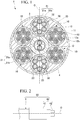
FIG. 1 is a cross-sectional view showing a configuration of a power supply cable of the present embodiment. -
FIG. 2 is a schematic diagram of a power supply cable with a connector provided with the power supply cable ofFIG. 1 . - Hereinafter, the configuration of a power supply cable according to the present embodiment will be described with reference to
FIG. 1 . - As shown in
FIG. 1 , apower supply cable 1 includes a plurality ofpower lines 10, afirst communication cord 20, a plurality ofsecond communication cords 30, afilling 2, and asheath 4. In the present embodiment, thepower supply cable 1 includes fourpower lines 10 and twosecond communication cords 30. Even number ofpower lines 10 andsecond communication cords 30 are provided. - The
power supply cable 1 is used, for example, when electrically connecting the charger and the power supply target object and supplying power to the power supply target. The power supply target may be an electric vehicle (vehicle) or the like. - In the case of quickly charging the battery for an electric vehicle using the
power supply cable 1, for example, a large current of 250 A or more flows through thepower line 10. Even in such a state that a large current is flowing, there is a possibility that the user directly touches thepower supply cable 1, therefore it is necessary to keep the temperature of the surface of thesheath 4 within a predetermined range. - Further, the
power supply cable 1 may be accommodated by being partially wound when not in use. When used, thepower supply cable 1 is pulled out from the partially wound accommodated state. That is, winding and pulling out of thepower supply cable 1 may be repeated. Therefore, durability against friction, durability against bending, flexibility, and the like are required for the entirepower supply cable 1. - Here, in the present embodiment, a direction along the central axis O of the
power supply cable 1 is referred to as a longitudinal direction. Further, in the cross-sectional view orthogonal to the central axis O, a direction orthogonal to the central axis O is referred to as a radial direction, and a direction revolving around the central axis O is referred to as a circumferential direction. - The
first communication cord 20 may be used for communication between, for example, a vehicle as a power supply target and a charger. In the cross-sectional view, thefirst communication cord 20 is disposed at the center of thepower supply cable 1. In the cross-sectional view, thefirst communication cord 20 is surrounded by fourpower lines 10 and twosecond communication cords 30. - The
first communication cord 20 includes a plurality (two) offirst signal lines 21, atape 22 that wraps around thefirst signal lines 21, and acover 23 covering thetape 22. The number of thefirst signal lines 21 included in thefirst communication cord 20 is smaller than the number of thesecond signal lines 31 included in thesecond communication cord 30. For example, the number offirst signal lines 21 is two and the number ofsecond signal lines 31 is six. - The
first communication cord 20 has flexibility. Thefirst signal line 21 has a configuration in which theconductor 21a is covered with aninsulator 21b. The plurality offirst signal lines 21 are accommodated in thecover 23 in a state of being integrally wound with thetape 22. - In the present embodiment, the two
first signal lines 21 are accommodated in thecover 23 in a twisted state. Onefirst communication cord 20 is a so-called twisted pair cable. Therefore, the adjustment range of the pitch for twisting the twofirst signal lines 21 can be increased, and an optimum pitch can be selected from the viewpoint of noise during communication. - The thickness of the
cover 23 is larger than the thickness of thetape 22. The thickness of thecover 23 is larger than the thickness of thetape 32 to be described later of thesecond communication cord 30. By changing the thickness of thecover 23, it is possible to adjust the outer diameter of thefirst communication cord 20 and easily adjust the position of eachsecond communication cord 30 and eachpower line 10 in the radial direction. Thus, eachsecond communication cord 30 and eachpower line 10 are in contact with thecover 23 in the radial direction, and thesecond communication cord 30 and thepower line 10, which are adjacent in the circumferential direction, or thepower lines 10 can be brought into contact with each other in the circumferential direction. In this way, by properly adjusting the thickness of thecover 23, eachsecond communication cord 30 and eachpower line 10 can be positioned around thefirst communication cord 20 in a well-balanced manner. - The
second communication cord 30 is disposed radially outward of thefirst communication cord 20. In the cross-sectional view shown inFIG. 1 , twosecond communication cords 30 are disposed so as to sandwich thefirst communication cord 20 in the radial direction. The outer diameter of thesecond communication cord 30 is substantially the same as the outer diameters of thefirst communication cord 20 and thepower line 10. The outer diameters of the twosecond communication cords 30 are substantially the same as each other. - The
second communication cord 30 has flexibility. Thesecond communication cord 30 includes sixsecond signal lines 31, and atape 32 that wraps around the second signal lines 31. Eachsecond signal line 31 is used for controlling the locking mechanism of theconnector 40 to be described later, the power source line of an LED that lights up at the time of power supply, and the signal line of the temperature sensor when theconnector 40 is provided with a temperature sensor. In addition, part of thesecond signal line 31 may be used as an auxiliary power supply line to the power supply target. - Each
second signal line 31 is wrapped with atape 32 in a state of being spirally twisted. Thesecond signal line 31 has a configuration in which theconductor 31a is covered with aninsulator 31b. The outer diameter of thesecond signal line 31 of thesecond communication cord 30 may be substantially the same as the outer diameter of thefirst signal line 21 of the first communication cord. Alternatively, the outer diameter of thesecond signal line 31 may be different from the outer diameter of thefirst signal line 21. - Each
power line 10 has onecooling tube 11, aconductor 12, and aninsulator 13. Thepower line 10 has flexibility. - The cooling
tube 11 is disposed at the center of thepower line 10. As the coolingtube 11, for example, a tube made ofnylon 12 can be used. Since thenylon 12 is excellent in heat resistance and insulation properties, it is suitable as a material of the coolingtube 11 which is in contact with theconductor 12 which generates heat by energization. In addition, since thenylon 12 is also excellent in flexibility and mechanical strength, it is suitable as a material of the inside of thepower supply cable 1 which is required to have flexibility and durability. In addition tonylon 12, as the material of the coolingtube 11, for example, other materials such as silicone resin, fluororesin, polyurethane, and polyolefin may be appropriately used. - Inside the cooling
tube 11, refrigerant such as liquid refrigerant, air, water, oil, and antifreeze liquid is filled. The refrigerant in the coolingtube 11 flows by a circulation device (not shown). The coolingtube 11 of the present embodiment has an outer diameter of 4.0 mm and an inner diameter of 2.5 mm. A low viscosity refrigerant is suitable for flowing inside the coolingtube 11 having a small inner diameter as described above. Further, since thepower supply cable 1 may be used in cold climates, a refrigerant that is an antifreeze liquid is suitable. The dimensions of the coolingtube 11 and the properties of the refrigerant are not limited to those described above, and may be changed as appropriate. - The
conductor 12 surrounds the coolingtube 11. For example, a direct current of 250 A or more flows through theconductor 12 in the present embodiment. Theconductor 12 is formed by winding a plurality ofconductor wires 12b around the coolingtube 11. In the present embodiment, theconductor wire 12b is formed by bundling and twisting 21strands 12a. Theconductor 12 is formed by collectively twisting tenconductor wires 12b around the coolingtube 11. Thus, theconductor 12 is evenly disposed around the coolingtube 11. For example, a tin plated soft copper wire can be used as eachstrand 12a constituting theconductor wire 12b. - The number of the
conductor wires 12b and thestrands 12a included in oneconductor 12 can be appropriately changed. In addition, the number ofconductor wires 12b andstrands 12a shown inFIG. 1 is appropriately changed for simplification of the drawing. - The
insulator 13 covers (surrounds) theconductor 12. As the material of theinsulator 13, for example, EP rubber can be used. - Each
power line 10 is disposed radially outward of thefirst communication cord 20. Onepower line 10 is sandwiched in the circumferential direction by thesecond communication cord 30 and anotherpower line 10. - In the cross-sectional view shown in
FIG. 1 , fourpower lines 10 are disposed at line-symmetrical positions with respect to the symmetry axis C passing through the centers of the twosecond communication cords 30. Further, since the twosecond communication cords 30 are disposed at positions sandwiching thefirst communication cord 20 in the radial direction, the symmetry axis C passes through the center of thefirst communication cord 20. In this way, eachpower line 10, thefirst communication cord 20, and eachsecond communication cord 30 are disposed such that the cross section of thepower supply cable 1 is line-symmetrical with respect to the symmetry axis C. Further, in the present embodiment, eachpower line 10, thefirst communication cord 20, and eachsecond communication cord 30 are disposed such that the cross section of thepower supply cable 1 is point-symmetrical with the center axis O as a center. Thus, it is possible to suppress occurrence of temperature unevenness in thepower supply cable 1 at the time of energization, to prevent the surface of thesheath 4 from locally becoming high temperature, and to further enhance safety. - The outer diameter of the
power line 10 is substantially the same as the outer diameters of thefirst communication cord 20 and thesecond communication cord 30. The outer diameters of the fourpower lines 10 are substantially the same as each other. - In the cross-sectional view, one of the
cooling tubes 11 respectively included in the pair ofpower lines 10 adjacent to each other in the circumferential direction is an outward path of the refrigerant, and the other is a return path of the refrigerant. In addition, the directions of the currents flowing through theconductors 12 respectively included in the pair ofpower lines 10 adjacent to each other are the same. - The
sheath 4 covers thepower line 10, thefirst communication cord 20, and eachsecond communication cord 30 integrally with the filling 2. Eachpower line 10 and eachsecond communication cord 30 are accommodated in thesheath 4 together with the filling 2 in a state of being spirally wrapped around thefirst communication cord 20. Thesheath 4 can be formed by extrusion molding or the like using, for example, chloroprene rubber or the like. - The filling 2 is filled around each
power line 10, thefirst communication cord 20, and eachsecond communication cord 30. The position of each member can be stabilized when the member is covered with thesheath 4, by the filling 2. Further, the filling 2 functions as a cushioning material for protecting thepower line 10 and thecommunication cords power supply cable 1 is stepped on the vehicle body or the like. As thefillings 2, for example, Tetoron threads or the like can be used. -
FIG. 2 is a schematic diagram of the power supply cable with aconnector 50 provided with thepower supply cable 1. As shown inFIG. 2 , the power supply cable with aconnector 50 includes apower supply cable 1, and a power supply connector (hereinafter simply referred to as a connector 40) disposed at a first end portion of thepower supply cable 1. - The
connector 40 is configured to be connected to the power supply target. Theconnector 40 includes acase 41 and a plurality ofconnector terminals 42. - The first end portion of the
power supply cable 1 is accommodated in thecase 41. Each of theconductors 12 in eachpower line 10 is electrically connected to eachconnector terminal 42. A pair ofcooling tubes 11 adjacent to each other in the circumferential direction in thepower line 10 are connected to each other by a connecting pipe (not shown) in thecase 41. One of the pair ofcooling tubes 11 is used as an outward path of the refrigerant, and the other is used as a return path of the refrigerant. Thus, the refrigerant flows in the order of the coolingtube 11 as the outward path, the connecting pipe, and the coolingtube 11 as the return path, and can cool both thepower supply cable 1 and theconnector 40. Since thepower supply cable 1 of the present embodiment includes four (two pairs of)power lines 10 andcooling tubes 11, two connecting pipes are accommodated in thecase 41. - The second end portion of the
power supply cable 1 is connected to a charger (not shown) having a refrigerant circulation device. The refrigerant in each coolingtube 11 is connected to the circulation device. Thus, the refrigerant circulates in thepower supply cable 1 and theconnector 40. InFIG. 2 , the connecting portion between thepower supply cable 1 and the above-described charger is not shown. - As described above, according to the present embodiment, since each
power line 10 has the coolingtube 11 and theconductor 12 surrounding the coolingtube 11, theconductor 12 in thepower line 10 is cooled by the coolingtube 11 from the inside thereof. Thus, since the inside of thepower line 10 which is the heat source is evenly cooled, temperature unevenness in thepower supply cable 1 is suppressed. This makes it possible to restrain thepower line 10, thefirst communication cord 20, thesecond communication cord 30, and the like accommodated in thepower supply cable 1 from locally becoming high temperature, in addition to the surface of thesheath 4. - Further, since the
power line 10, thefirst communication cord 20, andsecond communication cord 30 respectively have flexibility, thepower supply cable 1 as a whole has flexibility. Thus, for example, thepower supply cable 1 can be easily wound and accommodated in non-use or extended out in use, so thepower supply cable 1 excellent in handleability can be obtained. - Further, in the
power supply cable 1 of the present embodiment, the plurality ofpower lines 10 are disposed so as to surround thefirst communication cord 20, and thefirst communication cord 20 has acover 23 accommodating the plurality of first signal lines 21. With this configuration, by appropriately adjusting the thickness of thecover 23 of thefirst communication cord 20, the outer diameter of thefirst communication cord 20 can be changed. Thus, it is possible to easily adjust the radial position of eachpower line 10 surrounding thefirst communication cord 20 in thesheath 4. Thus, for example, each of thepower lines 10 is in contact with thefirst communication cord 20 in the radial direction and is in contact with anotherpower line 10 adjacent in the circumferential direction, which makes it difficult to change the position of each member in thesheath 4. - In addition, the plurality of
first signal lines 21 are accommodated in thecover 23 in a state of being integrally wound with thetape 22. With this configuration, for example, when extruding thecover 23, it is possible to prevent the softened material forming thecover 23 from entering between the first signal lines 21. Thus, it is possible to easily stabilize the thickness of thecover 23 and the outer diameter of thefirst communication cord 20, thereby the above-described effect could be more reliably achieved. - In addition, the
power supply cable 1 of the present embodiment includes a plurality ofsecond communication cords 30 having a plurality ofsecond signal lines 31, and a large number of communication means are provided. Further, eachsecond communication cord 30 and eachpower line 10 are disposed so as to surround thefirst communication cord 20. Therefore, as described above, the positions of themembers sheath 4 are hardly changed and durability against bending of thepower supply cable 1 can be maintained. - Further, the
power supply cable 1 of the present embodiment includes twosecond communication cords 30 and fourpower lines 10, and the total of sixsecond communication cords 30 andpower line 10 are disposed so as to surround thefirst communication cord 20 having substantially the same outer diameter as those of them. With this configuration, as shown inFIG. 1 , while thesecond communication cord 30 and thepower line 10 adjacent to each other are in contact with each other in the circumferential direction, eachsecond communication cord 30 and eachpower line 10 are in contact with thefirst communication cord 20 in the radial direction. Thus, the positions of thefirst communication cord 20, thesecond communication cord 30, and thepower line 10 in thesheath 4 are hardly changed, and these members can be disposed at a high density in thesheath 4. - Further, the position and attitude of each
member power line 10 and eachsecond communication cord 30 are wound around thefirst communication cord 20. This makes it difficult for the winding state to collapse, and it is also possible to simplify the manufacturing process and stabilize the quality when these members are accommodated in thesheath 4. - Since the number of the
first signal lines 21 included in thefirst communication cord 20 is small, the adjustment range of the thickness of thecover 23 accommodating thefirst signal lines 21 therein can be increased. This makes it easier to stabilize the position of eachmember 10, 20., 30 in thesheath 4, with thefirst communication cord 20 as the desired outer diameter, as described above. - Further, since a small number of
first signal lines 21 are twisted to each other, it is possible to increase the adjustment range of the pitch for twisting the first signal lines 21. This makes it possible to easily select an optimum twist pitch such that the influence of noise acting on thefirst signal line 21 is reduced. Further, by using thefirst signal line 21 for communication with the power supply target, it is possible to obtain apower supply cable 1 which is less susceptible to noise and ensures reliability of communication with the power supply target. - In addition, since a plurality of
first signal lines 21 twisted together are disposed at the center of thepower supply cable 1, even if thepower supply cable 1 is bent, the tension acting on eachfirst signal line 21 can be suppressed to be small. - Further, since the outer diameters of the plurality of
power lines 10 are substantially the same as each other, it is possible to reduce the cost by using therespective power lines 10 in common. It is possible to make the temperature of the surface of eachpower line 10 uniform, thereby more reliably suppressing temperature unevenness inside and outside thepower supply cable 1. - Further, since the power supply cable with a
connector 50 includes thepower supply cable 1, and theconnector 40 configured to be connected to the power supply target, it is possible to stably dispose each member in thesheath 4 while suppressing the occurrence of unevenness in temperature on the surface of thesheath 4 at the time of power supplying. - It should be noted that the technical scope of the present invention is not limited to the above-described embodiments, and various modifications can be made without departing from the spirit of the present invention.
- For example, in the above embodiment, the configuration including two
second communication cords 30 and fourpower lines 10 has been described. However, the number ofsecond communication cords 30 and the number ofpower lines 10 accommodated in thesheath 4 may be appropriately changed. Even in this case, thesecond communication cord 30 and thepower line 10 are disposed so as to surround thefirst communication cord 20, so it is possible to obtain the above-described action and effect. For example, the twosecond communication cords 30 and the twopower lines 10 may be disposed so as to surround thefirst communication cord 20. In this case, by setting the outer diameters of thesecond communication cord 30 and thepower line 10 to be substantially equal, and making the outer diameters smaller than the outer diameter of thefirst communication cord 20, it is possible to bring respective members adjacent to each other in the radial direction or the circumferential direction into contact with each other. - In the above embodiment, the configuration of the
second communication cord 30 is different from that of thefirst communication cord 20, but asecond communication cord 30 having the same configuration as that of thefirst communication cord 20 may be adopted. - Further, in the above-described embodiment, one of the
cooling tubes 11 respectively included in the pair ofpower lines 10 adjacent to each other is described as the outward path of the refrigerant, and the other is the return path of the refrigerant. However, the present invention is not limited thereto, each of thecooling tubes 11 respectively included in the pair ofpower lines 10 adjacent to each other may be a outward path or a return path of the refrigerant. - In the above embodiment, the directions of the currents flowing through the
conductors 12 respectively included in the pair ofpower lines 10 adjacent to each other are the same. However, the present invention is not limited thereto, and the directions of the currents flowing through theconductors 12 respectively included in the pair ofpower lines 10 adjacent to each other may be different from each other. - In the above embodiment, the
second communication cord 30 and thepower line 10 are disposed so as to surround thefirst communication cord 20, but the present invention is not limited thereto, and only thepower line 10 may be disposed so as to surround thefirst communication cord 20. In this case, thepower supply cable 1 is provided with sixpower lines 10, and the sixpower lines 10 may be disposed so as to surround thesecond communication cord 30 in cross-sectional view. - Further, in
FIG. 1 , twopower lines 10 and onesecond communication cord 30 are alternately disposed in the circumferential direction. With this configuration, thepower line 10 and thesecond communication cord 30 are disposed in a well-balanced manner, it is possible to suppress occurrence of temperature unevenness in thepower supply cable 1 at the time of energization, and to suppress the occurrence of a locally high temperature portion. This effect can be obtained by alternately disposing one or a plurality ofpower lines 10 and onesecond communication cord 30 in the circumferential direction. - Besides, without departing from the spirit of the present invention, it is possible to appropriately replace the constituent elements in the above-described embodiment with well-known constituent elements, and the above-described embodiment and modifications may be appropriately combined.
-
- 1
- power supply cable
- 2
- filling
- 4
- sheath
- 10
- power line
- 11
- cooling tube
- 12
- conductor
- 12a
- strand
- 12b
- conductor wire
- 13
- insulator
- 20
- first communication cord
- 21
- first signal line
- 22
- tape
- 23
- cover
- 30
- second communication cord
- 31
- second signal line
- 32
- tape
- 40
- connector
- 50
- power supply cable with a connector
Claims (7)
- A power supply cable comprising:a first communication cord having a first signal line and a cover accommodating therein the first signal line;a plurality of power lines each having a cooling tube, a conductor surrounding the cooling tube, and an insulator surrounding the conductor; anda sheath accommodating therein the first communication cord and the plurality of power lines,wherein in a cross-sectional view, the plurality of power lines are disposed so as to surround the first communication cord.
- The power supply cable according to claim 1,
wherein the first communication cord has a plurality of the first signal lines, and
wherein the plurality of first signal lines are accommodated in the cover in a state of being integrally wound with a tape. - The power supply cable according to claim 1 or 2,
wherein a second communication cord having a second signal line and the plurality of power lines are disposed so as to surround the first communication cord in the cross-sectional view. - The power supply cable according to claim 3,
wherein the number of second communication cords is two, and the number of the plurality of power lines is four, and
wherein the first communication cord, the two second communication cords, and the four power lines have substantially the same outer diameters. - The power supply cable according to any one of claims 1 to 4, further comprising:a second communication cord having a plurality of second signal lines,wherein the first communication cord has a plurality of the first signal lines, andwherein the number of the first signal lines of the first communication cord is smaller than the number of the second signal lines of the second communication cord.
- The power supply cable according to claim 5,
wherein the plurality of first signal lines are accommodated in the cover in a twisted state, and are used for communication with a power supply target. - A power supply cable with a connector, comprising:the power supply cable according to any one of claims 1 to 6; anda connector configured to be connected to a power supply target.
Applications Claiming Priority (2)
| Application Number | Priority Date | Filing Date | Title |
|---|---|---|---|
| JP2017013004A JP6201069B1 (en) | 2017-01-27 | 2017-01-27 | Power supply cable and power supply cable with connector |
| PCT/JP2018/001385 WO2018139335A1 (en) | 2017-01-27 | 2018-01-18 | Electricity-supplying cable, and connector-equipped electricity-supplying cable |
Publications (2)
| Publication Number | Publication Date |
|---|---|
| EP3576105A1 true EP3576105A1 (en) | 2019-12-04 |
| EP3576105A4 EP3576105A4 (en) | 2020-11-04 |
Family
ID=59895740
Family Applications (1)
| Application Number | Title | Priority Date | Filing Date |
|---|---|---|---|
| EP18744254.6A Withdrawn EP3576105A4 (en) | 2017-01-27 | 2018-01-18 | Electricity-supplying cable, and connector-equipped electricity-supplying cable |
Country Status (5)
| Country | Link |
|---|---|
| US (1) | US10629331B2 (en) |
| EP (1) | EP3576105A4 (en) |
| JP (1) | JP6201069B1 (en) |
| CN (1) | CN110073447A (en) |
| WO (1) | WO2018139335A1 (en) |
Cited By (3)
| Publication number | Priority date | Publication date | Assignee | Title |
|---|---|---|---|---|
| EP3582234A4 (en) * | 2017-02-07 | 2020-10-14 | Fujikura Ltd. | Power supply cable, and power supply cable with connector |
| EP3734618A1 (en) * | 2019-05-01 | 2020-11-04 | Prysmian S.p.A. | Charging system for an electric energy storage |
| EP4723142A1 (en) * | 2024-10-01 | 2026-04-08 | LEONI Kabel GmbH | Cooled conduit |
Families Citing this family (6)
| Publication number | Priority date | Publication date | Assignee | Title |
|---|---|---|---|---|
| KR20180096259A (en) * | 2017-02-21 | 2018-08-29 | 엘에스전선 주식회사 | Charging cable for electric vehicle |
| EP3761769B1 (en) * | 2018-04-02 | 2022-09-07 | Rocking Energy Intelligent Technology Co., Ltd. | Charging gun having excellent heat conduction and dissipation performance |
| US10714236B2 (en) * | 2018-06-13 | 2020-07-14 | Te Connectivity Corporation | Charging system with cooling tube |
| US12252024B2 (en) | 2019-09-05 | 2025-03-18 | Ls Cable & System Ltd. | Electric vehicle charging cable |
| EP4040451A4 (en) * | 2019-09-05 | 2023-08-30 | LS Cable & System Ltd. | ELECTRIC VEHICLE CHARGING CABLE |
| EP3910650B1 (en) * | 2020-05-11 | 2023-01-25 | Lapp Engineering AG | System for supplying shore-to-ship electrical power to ships docked in port |
Family Cites Families (22)
| Publication number | Priority date | Publication date | Assignee | Title |
|---|---|---|---|---|
| US306037A (en) * | 1884-09-30 | Thomas g | ||
| US1866611A (en) * | 1929-05-23 | 1932-07-12 | American Telephone & Telegraph | Concentric conducting system |
| JPS5397384U (en) | 1976-12-28 | 1978-08-08 | ||
| IT1163548B (en) * | 1983-06-21 | 1987-04-08 | Pirelli Cavi Spa | MULTI-POLE CABLE WITH FLUID OIL |
| JPH10106362A (en) * | 1996-08-07 | 1998-04-24 | Sumitomo Wiring Syst Ltd | Cooling cable for charging electric vehicle |
| US6350947B1 (en) * | 1999-09-07 | 2002-02-26 | Utilx Corporation | Flow-through cable |
| JP2001160322A (en) * | 1999-12-02 | 2001-06-12 | Toyota Autom Loom Works Ltd | Power supply cable |
| HUP0400422A2 (en) * | 2004-02-16 | 2005-12-28 | András Fazakas | Current conductor with braided wire |
| TWM340532U (en) * | 2008-01-15 | 2008-09-11 | Zheng-Xiong Wu | Energy-saving electric wire and cable |
| JP5673164B2 (en) | 2011-02-04 | 2015-02-18 | 日立金属株式会社 | 3-core cable |
| CN103339691B (en) | 2011-03-04 | 2015-09-02 | 株式会社润工社 | Transmission cable |
| DE102011100389A1 (en) * | 2011-05-04 | 2012-05-24 | Volkswagen Aktiengesellschaft | Charging cable for transmitting electrical energy in energy storage device of e.g. electric vehicle, has current conductor and coolant guiding device that are arranged within cable sheath |
| CN202145390U (en) | 2011-07-12 | 2012-02-15 | 青岛中核能线缆科技有限公司 | Photoelectric composite five-into-one net wire cable |
| US8350526B2 (en) * | 2011-07-25 | 2013-01-08 | Lightening Energy | Station for rapidly charging an electric vehicle battery |
| CN103137246A (en) * | 2011-11-23 | 2013-06-05 | 上海嘉泽实业有限公司 | Integrated electric welding machine cable and manufacture method thereof |
| CN202487259U (en) | 2012-02-02 | 2012-10-10 | 上海浦东电线电缆(集团)有限公司 | Water-cooled cable in intermediate frequency heavy current |
| US9321362B2 (en) * | 2014-02-05 | 2016-04-26 | Tesia Motors, Inc. | Cooling of charging cable |
| WO2016151752A1 (en) * | 2015-03-24 | 2016-09-29 | 日立金属株式会社 | Composite cable, composite harness and vehicle |
| JP2017013004A (en) | 2015-07-01 | 2017-01-19 | 旭化成株式会社 | Separation membrane module using hollow fiber carbon membrane |
| CN105118551A (en) * | 2015-08-28 | 2015-12-02 | 江苏中煤电缆有限公司 | Light-duty symmetric type low induction cable |
| DE102015120048A1 (en) * | 2015-11-19 | 2017-05-24 | Dr. Ing. H.C. F. Porsche Aktiengesellschaft | Electrical line arrangement |
| CA3250062A1 (en) * | 2016-05-20 | 2025-06-17 | Southwire Company, Llc | Liquid cooled charging cable system |
-
2017
- 2017-01-27 JP JP2017013004A patent/JP6201069B1/en not_active Expired - Fee Related
-
2018
- 2018-01-18 WO PCT/JP2018/001385 patent/WO2018139335A1/en not_active Ceased
- 2018-01-18 US US16/463,304 patent/US10629331B2/en not_active Expired - Fee Related
- 2018-01-18 EP EP18744254.6A patent/EP3576105A4/en not_active Withdrawn
- 2018-01-18 CN CN201880005057.7A patent/CN110073447A/en active Pending
Cited By (3)
| Publication number | Priority date | Publication date | Assignee | Title |
|---|---|---|---|---|
| EP3582234A4 (en) * | 2017-02-07 | 2020-10-14 | Fujikura Ltd. | Power supply cable, and power supply cable with connector |
| EP3734618A1 (en) * | 2019-05-01 | 2020-11-04 | Prysmian S.p.A. | Charging system for an electric energy storage |
| EP4723142A1 (en) * | 2024-10-01 | 2026-04-08 | LEONI Kabel GmbH | Cooled conduit |
Also Published As
| Publication number | Publication date |
|---|---|
| WO2018139335A1 (en) | 2018-08-02 |
| EP3576105A4 (en) | 2020-11-04 |
| JP2018120813A (en) | 2018-08-02 |
| US20190295743A1 (en) | 2019-09-26 |
| US10629331B2 (en) | 2020-04-21 |
| CN110073447A (en) | 2019-07-30 |
| JP6201069B1 (en) | 2017-09-20 |
Similar Documents
| Publication | Publication Date | Title |
|---|---|---|
| US10629331B2 (en) | Power supply cable and power supply cable with connector | |
| EP3582234A1 (en) | Power supply cable, and power supply cable with connector | |
| JP6078198B1 (en) | Power supply cable and power supply cable with connector | |
| US9117570B2 (en) | Copper clad aluminum wire, compressed conductor and cable including the same, and method of manufacturing compressed conductor | |
| US12567518B2 (en) | Coolable single line and charging cable | |
| JP6408619B2 (en) | Power supply cable and power supply cable with connector | |
| US20230411040A1 (en) | Reinforced electric wire and methods of making the same | |
| JP2018018809A (en) | Power supply cable and power supply cable with connector | |
| CN209880255U (en) | High-strength low-temperature-resistant communication cable | |
| JP6201070B1 (en) | Manufacturing method of power line with built-in cooling pipe | |
| JP6145556B1 (en) | Power supply cable and power supply cable with connector | |
| CN218214771U (en) | Liquid cooling charging cable | |
| CN218159759U (en) | Coaxial charging cable | |
| CN114005614B (en) | A high-current soft charging pile fast-charging external connection cable and preparation method thereof | |
| JP2018018837A (en) | Feed cable and connector-fitted feed cable | |
| CN115547552A (en) | Flat medium-voltage reel cable and manufacturing method thereof | |
| CN209822306U (en) | High-flexibility anti-torsion robot cable | |
| CN119069174A (en) | A coaxial liquid-cooled charging cable and a preparation method thereof | |
| JP2021077590A (en) | Supply cable and power feeding connector with cable | |
| CN115312253A (en) | Liquid cooling charging cable and production process | |
| CN108305709A (en) | A kind of robot cable |
Legal Events
| Date | Code | Title | Description |
|---|---|---|---|
| STAA | Information on the status of an ep patent application or granted ep patent |
Free format text: STATUS: THE INTERNATIONAL PUBLICATION HAS BEEN MADE |
|
| PUAI | Public reference made under article 153(3) epc to a published international application that has entered the european phase |
Free format text: ORIGINAL CODE: 0009012 |
|
| STAA | Information on the status of an ep patent application or granted ep patent |
Free format text: STATUS: REQUEST FOR EXAMINATION WAS MADE |
|
| 17P | Request for examination filed |
Effective date: 20190509 |
|
| AK | Designated contracting states |
Kind code of ref document: A1 Designated state(s): AL AT BE BG CH CY CZ DE DK EE ES FI FR GB GR HR HU IE IS IT LI LT LU LV MC MK MT NL NO PL PT RO RS SE SI SK SM TR |
|
| AX | Request for extension of the european patent |
Extension state: BA ME |
|
| DAV | Request for validation of the european patent (deleted) | ||
| DAX | Request for extension of the european patent (deleted) | ||
| A4 | Supplementary search report drawn up and despatched |
Effective date: 20201006 |
|
| RIC1 | Information provided on ipc code assigned before grant |
Ipc: H01B 7/00 20060101ALI20200930BHEP Ipc: B60L 53/18 20190101AFI20200930BHEP Ipc: H01B 7/18 20060101ALI20200930BHEP Ipc: H01R 13/46 20060101ALI20200930BHEP Ipc: H01B 7/42 20060101ALI20200930BHEP |
|
| STAA | Information on the status of an ep patent application or granted ep patent |
Free format text: STATUS: THE APPLICATION HAS BEEN WITHDRAWN |
|
| 18W | Application withdrawn |
Effective date: 20210312 |