EP3575887A1 - Watch case and wrist watch device - Google Patents
Watch case and wrist watch device Download PDFInfo
- Publication number
- EP3575887A1 EP3575887A1 EP19184088.3A EP19184088A EP3575887A1 EP 3575887 A1 EP3575887 A1 EP 3575887A1 EP 19184088 A EP19184088 A EP 19184088A EP 3575887 A1 EP3575887 A1 EP 3575887A1
- Authority
- EP
- European Patent Office
- Prior art keywords
- watch
- wrist
- watch case
- case
- strap
- Prior art date
- Legal status (The legal status is an assumption and is not a legal conclusion. Google has not performed a legal analysis and makes no representation as to the accuracy of the status listed.)
- Pending
Links
- 210000000707 wrist Anatomy 0.000 title claims abstract description 107
- 238000007373 indentation Methods 0.000 claims description 25
- 238000007789 sealing Methods 0.000 claims description 10
- 239000004033 plastic Substances 0.000 claims description 6
- 238000000034 method Methods 0.000 claims description 5
- 239000000463 material Substances 0.000 claims description 4
- 238000000465 moulding Methods 0.000 claims description 4
- 230000002035 prolonged effect Effects 0.000 claims description 4
- 239000002184 metal Substances 0.000 claims description 3
- 210000003414 extremity Anatomy 0.000 claims description 2
- 238000005242 forging Methods 0.000 claims description 2
- 238000003754 machining Methods 0.000 claims description 2
- XLYOFNOQVPJJNP-UHFFFAOYSA-N water Substances O XLYOFNOQVPJJNP-UHFFFAOYSA-N 0.000 description 13
- 239000000243 solution Substances 0.000 description 6
- 230000008901 benefit Effects 0.000 description 4
- 238000010276 construction Methods 0.000 description 3
- 230000006870 function Effects 0.000 description 3
- 230000000747 cardiac effect Effects 0.000 description 2
- 230000000694 effects Effects 0.000 description 2
- 239000011521 glass Substances 0.000 description 2
- 239000012535 impurity Substances 0.000 description 2
- 238000004519 manufacturing process Methods 0.000 description 2
- 239000004952 Polyamide Substances 0.000 description 1
- XUIMIQQOPSSXEZ-UHFFFAOYSA-N Silicon Chemical compound [Si] XUIMIQQOPSSXEZ-UHFFFAOYSA-N 0.000 description 1
- 230000006978 adaptation Effects 0.000 description 1
- 238000004026 adhesive bonding Methods 0.000 description 1
- 239000000919 ceramic Substances 0.000 description 1
- 238000004140 cleaning Methods 0.000 description 1
- 239000013078 crystal Substances 0.000 description 1
- 230000007547 defect Effects 0.000 description 1
- 230000001419 dependent effect Effects 0.000 description 1
- 238000001746 injection moulding Methods 0.000 description 1
- 230000010354 integration Effects 0.000 description 1
- 230000008447 perception Effects 0.000 description 1
- 229920002647 polyamide Polymers 0.000 description 1
- 238000007493 shaping process Methods 0.000 description 1
- 229910052710 silicon Inorganic materials 0.000 description 1
- 239000010703 silicon Substances 0.000 description 1
Images


Classifications
-
- G—PHYSICS
- G04—HOROLOGY
- G04G—ELECTRONIC TIME-PIECES
- G04G17/00—Structural details; Housings
- G04G17/08—Housings
-
- G—PHYSICS
- G04—HOROLOGY
- G04B—MECHANICALLY-DRIVEN CLOCKS OR WATCHES; MECHANICAL PARTS OF CLOCKS OR WATCHES IN GENERAL; TIME PIECES USING THE POSITION OF THE SUN, MOON OR STARS
- G04B37/00—Cases
- G04B37/0008—Cases for pocket watches and wrist watches
- G04B37/0058—Cases for pocket watches and wrist watches for shaped watches
-
- G—PHYSICS
- G04—HOROLOGY
- G04B—MECHANICALLY-DRIVEN CLOCKS OR WATCHES; MECHANICAL PARTS OF CLOCKS OR WATCHES IN GENERAL; TIME PIECES USING THE POSITION OF THE SUN, MOON OR STARS
- G04B37/00—Cases
- G04B37/14—Suspending devices, supports or stands for time-pieces insofar as they form part of the case
- G04B37/1486—Arrangements for fixing to a bracelet
-
- G—PHYSICS
- G04—HOROLOGY
- G04G—ELECTRONIC TIME-PIECES
- G04G21/00—Input or output devices integrated in time-pieces
- G04G21/04—Input or output devices integrated in time-pieces using radio waves
-
- G—PHYSICS
- G04—HOROLOGY
- G04R—RADIO-CONTROLLED TIME-PIECES
- G04R60/00—Constructional details
- G04R60/06—Antennas attached to or integrated in clock or watch bodies
- G04R60/10—Antennas attached to or integrated in clock or watch bodies inside cases
Definitions
- the present invention pertains to a watch case adapted to be integrated into a wrist watch device, the watch case comprising an inner volume for housing internal components of said wrist watch device and attachment means for attaching at least one watch strap of said wrist watch device, as well as to a corresponding watch strap respectively a corresponding wrist watch device.
- the present invention is situated in the context of wrist watches, respectively so-called wrist computers, which nowadays may be equipped with numerous functions, including for example location determination, especially by means of the global positioning system (GPS), capture and analysis of the cardiac frequency of the user of the device, altimetric - and barometric applications, and the like.
- GPS global positioning system
- These diverse functions requiring corresponding electronic components inside the watch, such wrist computers usually are quite voluminous and, in particular, often need to be equipped with watch cases of rather large size, some of these devices having in fact a width of 4 cm to 6 cm or even more. This has consequences on several aspects both on the level of the case as of the whole device.
- a first aspect is induced by the fact that conventional wrist watch cases are provided at opposite lateral ends with the watch straps allowing the user to secure the device on his wrist.
- this causes a large distance between the respective ends of the watch straps, i.e. between their axes of attachment to the watch case. Consequently, devices equipped with such large cases are rather uncomfortable, if not impossible, to wear by persons having a small wrist diameter.
- This aspect is even worse for a category of conventional wrist computers which have a case made up of a first part of appreciably circular shape which is prolonged in the direction of one of its watch straps by a second part of appreciably longitudinal shape and of similar width like said watch strap.
- a second aspect caused by the large size of such devices lies in the body of the watch case itself.
- watch cases for such devices may have quite complicated shapes, e. g. in the above-mentioned case of watch cases made up of a first part of appreciably circular shape prolonged by a second, downwards bent part of appreciably longitudinal shape.
- Prior art watch cases of this type are made up of several parts, usually of a bottom part having approximately half of the height of the whole watch case and of at least one cover part which provides for the remaining height and is fitted onto the bottom part, these parts forming together the main body of the watch case.
- Such splitting of the main housing of the wrist computer into two or more parts may have some advantages from the point of view of manufacturing the parts of the watch case and of the simplicity of assembling the whole device.
- Watch cases with a main body made up of several parts suffer drawbacks in this respect, because of evidently being less robust, since any bonding between parts is typically a weakness in construction, as well as being less easy to use by the end user.
- boundary interfaces between the housing parts of such conventional watch cases form edges collecting impurities which will need frequent cleaning by the user.
- boundary interfaces impose limits on the design of the device and are potentially negative for its aesthetic perception, since not allowing to have surfaces with a clean look all over the watch case.
- ensuring water tightness on 3D (not flat) interconnecting surfaces is more challenging, hence costly and subject to defects.
- the object of the present invention to overcome the above-mentioned disadvantages. It is particularly an object to realize a watch case of rather large size allowing both integration of numerous electronic components required by the corresponding watch device and comfortable wear of the same by all persons irrespective of their wrist diameter. It is also an object to have a watch being of robust and relatively simple construction, leaving a maximum of usable space in its inside. It is also an object to have a watch assuring optimal water tightness and aesthetic appearance, as well as keeping its production cost comparatively low. Furthermore, it is the object of the present invention to realize corresponding watch straps to be used in connection with such a watch case as well as a corresponding wrist watch device incorporating such a watch case.
- the present invention proposes a watch case which is characterized by the features enumerated in claim 1, respectively a corresponding watch strap according to claim 16 and a wrist watch device according to claim 18, which all allow to achieve the objectives identified above.
- the watch case according to the present invention distinguishes from prior art by the fact that at least one portion of said inner volume of the watch case extends laterally beyond the points of attachment of said at least one watch strap.
- the points of attachment of said at least one watch strap are situated above the plane of the bottom of the watch case.
- the watch case provides an attachment for the watch straps situated both higher in relation to the watch case and closer to each other, it is possible to provide a solution to the above-mentioned technical problems, in particular to allow comfortable wear of corresponding wrist watch devices also for people having a smaller wrist circumference.
- the watch case comprises an inner volume for housing internal components of said wrist watch device and attachment means for attaching at least one watch strap of said wrist watch device, at least one portion of said inner volume of the watch case extends laterally and the watch case has a body made of one single piece.
- the inner volume of the main body of the watch case for housing internal components of the wrist watch device furthermore comprises just one single opening oriented towards the opposite side of the bottom of the watch case, and the single opening is delimited by a surface lying in a plane, with the delimiting surface of the inner volume having, in an even more preferred embodiment, an appreciably circular circumference.
- the watch case is particularly adapted to be used for wrist watch devices and wrist computers requiring water tightness, since the sealing may be realized in simple, space saving, and very safe manner by a single gasket of annular shape mounted on the circular opening having one single sealing plane. Moreover, the resulting watch case may be designed in an aesthetically attractive manner having a clean surface look and is particularly robust, since being of one piece.
- the invention also relates to corresponding watch straps and wrist watch devices being equipped with a watch case according to the present invention.
- Figure 1a is an exploded perspective top view on a wrist watch device comprising a watch case as well as watch straps according to the present invention
- figure 1b is a perspective bottom view on the wrist watch device according to figure 1a , the watch case being in the assembled state, whereas the corresponding watch straps are shown in disassembled state.
- Figure 2a is a schematic top view of the wrist watch device according to the present invention in its assembled state;
- figure 2b is a side elevation of the wrist watch device illustrated in figure 2a of the face of the device which comprises a portion of the inner volume of the watch case extending laterally beyond the points of attachment of the watch strap mounted on this side of the wrist watch device.
- Figures 3a and 3b show sectional views of the wrist watch device along the lines I-I respectively II-II indicated in figures 2a and 2b .
- Figure 4a shows a side elevation of the wrist watch device according to figure 2a on one of the sides of the device comprising the command means; figure 4b and 4c show sectional views of the wrist watch device along the lines III-III respectively IV-IV indicated in figure 4a .
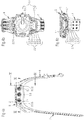
- a watch case 1, 2 such as proposed by the present invention is adapted to form part of a wrist watch device, like the type of wrist computers mentioned in the introduction.
- the watch case 1 according to the present invention comprises a main body 2 for the watch case, an annular securing ring 3 which is situated in the assembled state of the watch case at the upper end of the main body 2 near its opening 2.4 and allows to secure the other components of the device, like e.g.
- the watch crystal 6 may be fixed directly in water tight manner on the annular cover 5 or pressed by the latter against the watch case main body 2 respectively the securing ring 3, since the annular cover 5 is rigidly mounted on the main body 2 of the watch case, for example by screws such as shown in figure 1a or by other equivalent means.
- the gasket 4 has a general annular shape and may include inwardly curved portions 4.1 allowing the screw holes to be maintained out of the sealed volume.
- the gasket 4 is made of plastic, for example of polyamide or of a similar material.
- the sealing function of the gasket could also be performed by other techniques such as gluing, 2-sided tape, and rubber or silicon o-ring.
- the gasket has of course a shape adapted to the shape of the watch case and can have a general circular shape as shown in the figure, or an oval or square shape depending on the shape of the watch case. It is also important to note that the gasket 4 is generally flat and that its median plane lies in a single plane, which facilitates and enables a cheaper sealing solution.
- the gasket groove 2.4.1 can have a wedge shape.
- the diverse other components of a corresponding wrist watch device like the watch movement, energy source, or other parts, are not shown in the figures for reasons of clarity, since these are not essential for the present invention.
- the watch case main body 2 comprises an inner volume 2.1 for housing said internal components of the wrist watch device.
- the inner volume 2.1 may be perceived as having a central part 2.1.1 of appreciably circular shape prolonged laterally on at least one side, towards the direction of the zone where watch straps 7, 8 are mounted on the watch case, by a lateral part 2.1.2 of appreciably longitudinal shape.
- FIG. 1b shows a perspective bottom view on the wrist watch device with the watch case being in the assembled state
- the corresponding watch straps being shown in disassembled state
- such prolongation of the watch case 1, 2 is useful for wrist computers in order to allow the inner volume 2.1 to be of sufficient size for housing all necessary other components of such a device, especially all types of electronic components including the normal watch movement, the energy source, as well as supplementary equipment.
- the latter may for example consist in devices like a GPS receiver and its antenna required for nowadays location determination systems, pressure capture devices required for altimeters and barometers, detectors of the cardiac frequency, or even radio receivers, etc.
- the watch case 1, respectively its main body 2 also comprises attachment means 2.2 for attaching at least one watch strap 7, 8 of said wrist watch device, such as visible in figures 1a and 1b , too.
- both watch straps 7, 8 are attached by the attachment means 2.2 respectively are of the type that will be described in more detail in a later section of this description.
- one of the distinguishing features of the watch case according to the present invention with respect to prior art consists in that at least one portion 2.1.2 of said inner volume 2.1 of the watch case 1, 2, in particular said lateral part 2.1.2 of appreciably longitudinal shape of the inner volume 2.1 which is particularly adapted to house any supplementary electronic component of the wrist watch device like e.g. a GPS receiver and antenna, extends laterally beyond the points of attachment 2.2.6 of said at least one watch strap 7, 8.
- This feature is particularly well perceptible in figures 3a and 3b which show sectional views of the wrist watch device along the lines I-I respectively II-II indicated in figures 2a and 2b .
- FIG. 2a is a schematic top view of the wrist watch device according to the present invention in its assembled state
- FIG. 2b shows a side elevation of the same wrist watch device, viewed from the face of the device which comprises the portion 2.1.2 of the inner volume 2.1 of the watch case extending laterally beyond the points of attachment 2.2.6 of the watch strap 7 which is mounted on this side of the wrist watch device.
- Figure 3a schematically illustrates a preferred, but not necessarily required configuration of the watch case 1, 2 according to the present invention which further distinguishes in that said at least one laterally extending portion 2.1.2 of the inner volume 2.1 of the watch case is situated at least partially underneath the plane 2.3.1 of the bottom 2.3 of the watch case, which allows to further increase the usable volume whilst following the natural shape of the human wrist.
- the at least one portion 2.1.2 of said inner volume 2.1 of the watch case extending laterally beyond the points of attachment 2.2.6 of said at least one watch strap 7, 8 may be situated only on one side of the watch case 1, 2, next to the zone of the watch case comprising the attachment means 2.2 for attaching one of the watch straps 7, 8, or on both sides of the watch case, i.e. next to both zones of the watch case comprising the attachment means 2.2 for attaching the watch straps 7, 8.
- the watch case 1, 2 may comprise, depending on the number of electronic components to be housed or other parameters influencing the design of the watch case, lateral prolongations on one or on both sides, with corresponding adaptation of the watch case and watch straps on each side concerned.
- Figure 3b illustrates the even more preferred embodiment comprising the additional feature, shown by the way in all figures but not necessarily required either, that the points of attachment 2.2.6 of said at least one watch strap 7, 8 are situated above the plane 2.3.1 of the bottom 2.3 of the watch case, such that the virtual axes of rotation for attachment of the watch straps 7, 8 are situated especially high as compared to the height of the watch case 1, 2.
- said points of attachment 2.2.6 of said at least one watch strap 7, 8, respectively the virtual axes of rotation for attachment of the watch straps 7, 8 may be situated at a height of about 30% to 60% of the total height of the main body 2 of the watch case 1.
- the distance D A between the points of attachment 2.2.6 of the first watch strap 7 and the points of attachment 2.2.6 of the second watch strap 8 of the wrist watch device i.e the distance between the two virtual axes of rotation for attachment of the two watch straps 7 and 8 is preferably situated in the range of 50% to 90% of the total width W T of the watch case, in particular in the range of 65% to 85% of the total width W T of the watch case.
- the axes of rotation of the watch straps 7, 8 thus may be arranged such as to be particularly close to each other in view of the size of the watch case 1, 2.
- a watch case 1, 2 Another important feature of a watch case 1, 2 according to the present invention consists in that the attachment means 2.2 for attaching said at least one watch strap 7, 8 of said wrist watch device to the watch case 1, 2 are shaped and positioned such as not to traverse the at least one portion 2.1.2 of said inner volume 2.1 of the watch case extending laterally beyond the points of attachment 2.2.6 of said at least one watch strap 7, 8.
- figures 4b and 4c show sectional views of the wrist watch device along the lines III-III respectively IV-IV indicated in figure 4a , the latter being a side elevation of the wrist watch device viewed from one of the sides of the device comprising the command means for the wrist watch, like for example push buttons, a watch crown, or the like.
- said attachment means 2.2 do not traverse the lateral part 2.1.2 of appreciably longitudinal shape of the inner volume 2.1, which is important in order to optimally provide supplementary space for the internal components of the wrist watch device.
- Figure 4c shows that this is the case even, and in particular, in the embodiment of the watch case 1, 2 where the points of attachment 2.2.6, i.e. the virtual axes of rotation, of said at least one watch strap 7, 8 are situated above the plane 2.3.1 of the bottom 2.3 of the watch case.
- the points of attachment 2.2.6 of the watch straps 7, 8 may be placed, if, of course, under certain limits, nevertheless at a rather freely selectable portion both of the height as well as of the width of the watch case 1, 2, such as to allow a particularly comfortable wear of larger wrist watch devices also for people having a smaller wrist.
- this is achieved by the use of non-traversing attachment means 2.2, or alternatively, like shortly mentioned above, by placing the points of attachment 2.2.6 of the watch straps 7, 8 such that the virtual axes of rotation for attachment of the watch straps 7, 8 are inside the wall of the bottom 2.3 of the watch case.
- the latter solution has, however, the drawback of a lower position of the points of attachment 2.2.6 of the watch straps 7, 8 relative to the watch case.
- it is the combination of the high position of the points of attachment 2.2.6 of the watch straps 7, 8 relative to the watch case and the rimpedement of the axes of rotation of the watch straps 7, 8 as compared to the total width of the watch case which allows to optimally design the wear comfort in view of a watch case of given size and shape.
- the attachment means 2.2 for attaching said at least one watch strap 7, 8 of said wrist watch device to the watch case comprise, as can be seen for example in the perspective view of figure 1b or the sectional views of figures 4b and 4c , lateral recesses or indentations 2.2.1, 2.2.2 formed within the external side of the watch case and extending appreciably upwards from of the bottom 2.3 of the watch case.
- the attachment means 2.2 for attaching said at least one watch strap 7, 8 of said wrist watch device to the watch case 1, 2 comprise mounting means 2.2.4, 2.2.5 adapted to be housed inside said lateral indentations 2.2.1, 2.2.2 formed within the external side of the watch case.
- said mounting means comprise watch strap holding means 2.2.4 and/or securing means 2.2.5.
- said lateral indentations 2.2.1, 2.2.2 formed within the external side of the watch case comprise, for each watch strap 7, 8, a pair of first lateral indentations 2.2.1 of larger size and usually situated at the outer periphery of the bottom 2.3 of the watch case directed to the watch strap 7, 8 to be mounted.
- the pair of first lateral indentations 2.2.1 is adapted to house corresponding ends 7.1, 8.1 of the watch strap 7, 8 to be mounted on the watch case.
- said lateral indentations 2.2.1, 2.2.2 formed within the external side of the watch case comprise a corresponding pair of second lateral indentations 2.2.2 adapted to house said securing means 2.2.5, each of the second lateral indentations being 2.2.2 situated next to the corresponding first lateral indentation 2.2.1 and separated from this first lateral indentation by a wall 2.2.3 comprising a traversing hole adapted to house said watch strap holding means 2.2.4.
- the watch strap holding means 2.2.4 are realized by screws and said securing means 2.2.5 are realized by corresponding nuts.
- Others attachments means can also be used to fix the wrist strap to the watch case.
- Examples of others attachments means includes: over molded strap with relief by lateral extension, screws/thread inserts in plastic; pressed in studs; snap connection; self threading screws; screws and nuts replaced with shafts and locking rings. More generally, any other known attachment methods from watch industry can be used.
- a watch case 1 Another important feature of a watch case 1 according to the present invention consists in that, in the most preferred embodiment, the body 2 of the watch case 1 is made of a single piece. This allows to provide a particularly robust main body 2 of the watch case which, moreover, has the benefit of being aesthetically attractive and having a clean look. Also, the total number of pieces of the watch case 1 may be reduced to a minimum. As visible in figure 1a , the whole of the watch case 1 comprises in this configuration only the main body 2, the securing ring 3, the gasket 4, and the annular cover 5 with the watch glass 6. To this effect, the body 2 of the watch case may be produced in one piece using molding techniques, preferentially by plastic tooling/molding. Usually, the material used for the body 2 is hard plastic.
- the watch case 1 such that the inner volume 2.1 of the main body 2 of the watch case 1 for housing internal components of said wrist watch device comprises only one single opening 2.4 oriented towards the opposite side of the bottom 2.3 of the watch case, such as may be seen for example in figures 1a and 3a .
- the only further openings of the main body 2 of the watch case 1 are situated laterally and provide openings for the watch command means which are typically push buttons of known design, this being visible for example in figures 1b or 4a .
- said single opening 2.4 is preferably delimited by an outline lying in a single plane, this enabling a better and cheaper sealing connection.
- the top surface deliminating said single opening 2.4 lies preferably in the same single plane, and, even more preferably, said delimiting surface of the inner volume 2.1 of the watch case lying in a single plane has a circular circumference, although the circumference may, of course, have any other shape, e.g. oval or rectangular.
- Such circular delimiting surface is particularly well adapted to be used as sealing boundary, since a sealing gasket 4 of simple, appreciably circular shape and requiring little space may be used to obtain a robust and safe water tightness sealing.
- the top surface deliminating the single opening may also have a wedge shape, i.e. do not lies in the same plan as the outline (e.g. being frustroconical).
- the present invention also concerns a watch strap 7, 8 being adapted to be used in connection with a watch case 1, 2 such as described here above.
- a watch strap 7, 8 has at its extremity to be mounted on the watch case 1, 2 an appreciably U-shaped end portion corresponding in shape and tightly fitting to the external shape of the watch case.
- the detailed shape of the U-shaped end portion of the watch strap 7, 8 thus may vary to some extent without departing from the present invention.
- the ends 7.1, 8.1 of the U-shaped end portion are adapted for cooperation with above mentioned the indentations 2.2.1, 2.2.2 formed within the watch case 1, 2 as well as with said mounting means 2.2.4, 2.2.5, such as to assure, in the assembled state, attachment of the watch strap 7, 8 to the watch case as well as covering of said indentations 2.2.1, 2.2.2 by the watch strap.
- the latter allows to improve the aesthetic appearance of the assembled wrist watch device by covering said indentations 2.2.1, 2.2.2 as well as to avoid impurities to enter into these recesses in the watch case.
- the exact shape of the ends 7.1, 8.1 of the watch straps 7, 8 may vary to some extent depending on the shape of the watch case 1, 2 respectively its indentations 2.2.1, 2.2.2, without departing from the present invention.
- the present invention also relates to any wrist watch device comprising a watch case 1, 2 and/or a watch strap 7, 8 such as described here above.
- a wrist watch device comprises an additional component that is housed in the lateral part 2.1.2 of appreciably longitudinal shape of the inner volume 2.1.
- the wrist watch device or wrist computer according to the present invention may especially comprise a global positioning system (GPS) unit, i.e. a GPS receiver and antenna which are at least partially housed in said lateral part 2.1.2.
- GPS global positioning system
- Such devices independently of the functionality of the component to be housed in the lateral part 2.1.2, may readily be realized by a person skilled in the art having taken note of the teaching in the present disclosure.
- a watch case according to the present invention provides an attachment for the watch straps situated both higher in relation to the watch case and closer to each other, it is possible to provide a solution to the above mentioned technical problems with respect to wear comfort of large watch cases, in particular to allow comfortable wear of corresponding wrist watch devices of large size also for people having a smaller wrist circumference.
- a watch case according to the present invention having, moreover and if desired, a body made of one single piece, is particularly adapted for wrist watch devices and wrist computers requiring excellent water tightness, since the sealing of such a watch case may be realized in simple, space saving, and very safe manner by a single gasket mounted on the circular opening.
- This configuration is especially advantageous if the main body of the watch case made of a single piece has an inner volume comprising one single upwards opening which is delimited by a circular surface lying in a plane.
- the resulting watch case is particularly robust, because of being of one piece, and may be designed in an aesthetically attractive manner with a peculiarly clean surface look.
- the case bottom has a battery receiving cavity with a sealed cover allowing easy access for battery replacement.
Abstract
Description
- The present invention pertains to a watch case adapted to be integrated into a wrist watch device, the watch case comprising an inner volume for housing internal components of said wrist watch device and attachment means for attaching at least one watch strap of said wrist watch device, as well as to a corresponding watch strap respectively a corresponding wrist watch device.
- In general, the present invention is situated in the context of wrist watches, respectively so-called wrist computers, which nowadays may be equipped with numerous functions, including for example location determination, especially by means of the global positioning system (GPS), capture and analysis of the cardiac frequency of the user of the device, altimetric - and barometric applications, and the like. These diverse functions requiring corresponding electronic components inside the watch, such wrist computers usually are quite voluminous and, in particular, often need to be equipped with watch cases of rather large size, some of these devices having in fact a width of 4 cm to 6 cm or even more. This has consequences on several aspects both on the level of the case as of the whole device. A first aspect is induced by the fact that conventional wrist watch cases are provided at opposite lateral ends with the watch straps allowing the user to secure the device on his wrist. In the mentioned case of large wrist computers this causes a large distance between the respective ends of the watch straps, i.e. between their axes of attachment to the watch case. Consequently, devices equipped with such large cases are rather uncomfortable, if not impossible, to wear by persons having a small wrist diameter. This aspect is even worse for a category of conventional wrist computers which have a case made up of a first part of appreciably circular shape which is prolonged in the direction of one of its watch straps by a second part of appreciably longitudinal shape and of similar width like said watch strap. In fact, such prolongation is often required to have sufficient space for all electronic components, including the normal watch movement, the energy source, as well as supplementary equipment like a GPS receiver and antenna, etc.. With the corresponding watch strap being in such conventional devices attached to the outer end of said longitudinal watch case prolongation, the distance between the respective ends of the watch straps is thus further increased. This means that the disadvantage in view of the wearing of such devices by persons having a small wrist is even more accentuated for such kind of devices, even though the watch case prolongation is usually inclined downwards in order to better fit the shape of a human wrist.
- A second aspect caused by the large size of such devices lies in the body of the watch case itself. In fact, watch cases for such devices may have quite complicated shapes, e. g. in the above-mentioned case of watch cases made up of a first part of appreciably circular shape prolonged by a second, downwards bent part of appreciably longitudinal shape. Prior art watch cases of this type are made up of several parts, usually of a bottom part having approximately half of the height of the whole watch case and of at least one cover part which provides for the remaining height and is fitted onto the bottom part, these parts forming together the main body of the watch case. Such splitting of the main housing of the wrist computer into two or more parts may have some advantages from the point of view of manufacturing the parts of the watch case and of the simplicity of assembling the whole device. However, there are important disadvantages of such construction, especially due to the fact that the individual parts making up the watch case in most of the cases need to be assembled in water tight manner, given that most wrist computers are designed for applications requiring water tightness. A main housing with a split design, of course, requires a gasket of quite complicated shape, which by definition may cause future problems in view of the water tightness of the device. Also, the total surface to be sealed is increased, which not only diminishes reliability of water tightness but moreover is voluminous, thus further reducing the space available for the electronic components of the device. At the same time, wrist computers usually are exposed to all kind of situations and therefore need to be designed both in robust and easy to use manner. Watch cases with a main body made up of several parts suffer drawbacks in this respect, because of evidently being less robust, since any bonding between parts is typically a weakness in construction, as well as being less easy to use by the end user. For example, boundary interfaces between the housing parts of such conventional watch cases form edges collecting impurities which will need frequent cleaning by the user. At the same time, such boundary interfaces impose limits on the design of the device and are potentially negative for its aesthetic perception, since not allowing to have surfaces with a clean look all over the watch case. Moreover, ensuring water tightness on 3D (not flat) interconnecting surfaces is more challenging, hence costly and subject to defects.
- Prior art watch cases and wrist watch devices of the type described here above thus inherently comprise several problems and disadvantages. Therefore, there is a need for a watch case, for corresponding watch straps, as well as for a wrist watch device lacking these drawbacks and difficulties.
- It is thus the object of the present invention to overcome the above-mentioned disadvantages. It is particularly an object to realize a watch case of rather large size allowing both integration of numerous electronic components required by the corresponding watch device and comfortable wear of the same by all persons irrespective of their wrist diameter. It is also an object to have a watch being of robust and relatively simple construction, leaving a maximum of usable space in its inside. It is also an object to have a watch assuring optimal water tightness and aesthetic appearance, as well as keeping its production cost comparatively low. Furthermore, it is the object of the present invention to realize corresponding watch straps to be used in connection with such a watch case as well as a corresponding wrist watch device incorporating such a watch case.
- To this effect, the present invention proposes a watch case which is characterized by the features enumerated in claim 1, respectively a corresponding watch strap according to claim 16 and a wrist watch device according to claim 18, which all allow to achieve the objectives identified above. In particular, the watch case according to the present invention distinguishes from prior art by the fact that at least one portion of said inner volume of the watch case extends laterally beyond the points of attachment of said at least one watch strap. In a preferred embodiment, the points of attachment of said at least one watch strap are situated above the plane of the bottom of the watch case.
- By these means, due to the fact that the watch case provides an attachment for the watch straps situated both higher in relation to the watch case and closer to each other, it is possible to provide a solution to the above-mentioned technical problems, in particular to allow comfortable wear of corresponding wrist watch devices also for people having a smaller wrist circumference.
- Moreover, in another preferred embodiment, the watch case comprises an inner volume for housing internal components of said wrist watch device and attachment means for attaching at least one watch strap of said wrist watch device, at least one portion of said inner volume of the watch case extends laterally and the watch case has a body made of one single piece. Advantageously, the inner volume of the main body of the watch case for housing internal components of the wrist watch device furthermore comprises just one single opening oriented towards the opposite side of the bottom of the watch case, and the single opening is delimited by a surface lying in a plane, with the delimiting surface of the inner volume having, in an even more preferred embodiment, an appreciably circular circumference.
- Due to these features, the watch case is particularly adapted to be used for wrist watch devices and wrist computers requiring water tightness, since the sealing may be realized in simple, space saving, and very safe manner by a single gasket of annular shape mounted on the circular opening having one single sealing plane. Moreover, the resulting watch case may be designed in an aesthetically attractive manner having a clean surface look and is particularly robust, since being of one piece.
- The invention also relates to corresponding watch straps and wrist watch devices being equipped with a watch case according to the present invention.
- Other features and advantages of the present invention are mentioned in the dependent claims as well as in the description disclosing in the following, with reference to the figures, the invention in more detail.
- The attached figures schematically and by way of example illustrate the principles of the present invention.
-
Figure 1a is an exploded perspective top view on a wrist watch device comprising a watch case as well as watch straps according to the present invention;figure 1b is a perspective bottom view on the wrist watch device according tofigure 1a , the watch case being in the assembled state, whereas the corresponding watch straps are shown in disassembled state. -
Figure 2a is a schematic top view of the wrist watch device according to the present invention in its assembled state;figure 2b is a side elevation of the wrist watch device illustrated infigure 2a of the face of the device which comprises a portion of the inner volume of the watch case extending laterally beyond the points of attachment of the watch strap mounted on this side of the wrist watch device. -
Figures 3a and 3b show sectional views of the wrist watch device along the lines I-I respectively II-II indicated infigures 2a and 2b . -
Figure 4a shows a side elevation of the wrist watch device according tofigure 2a on one of the sides of the device comprising the command means;figure 4b and 4c show sectional views of the wrist watch device along the lines III-III respectively IV-IV indicated infigure 4a . - In the following, the invention shall be described in detail with reference to the above-mentioned figures.
- As can be seen in convenient manner in
figure 1a which shows an exploded perspective top view on a wrist watch device comprising a watch case as well as watch straps according to the present invention, awatch case 1, 2 such as proposed by the present invention is adapted to form part of a wrist watch device, like the type of wrist computers mentioned in the introduction. In particular, the watch case 1 according to the present invention comprises amain body 2 for the watch case, an annular securing ring 3 which is situated in the assembled state of the watch case at the upper end of themain body 2 near its opening 2.4 and allows to secure the other components of the device, like e.g. the watch movement, the energy source, et cetera, inside thewatch case body 2, a gasket 4 also situated in the assembled state of the watch case at the level of the opening 2.4 of themain body 2 in a specific gasket groove 2.4.1 and guaranteeing water tightness of thewatch case 2, and anannular cover 5 with thewatch glass 6. Thewatch crystal 6 may be fixed directly in water tight manner on theannular cover 5 or pressed by the latter against the watch casemain body 2 respectively the securing ring 3, since theannular cover 5 is rigidly mounted on themain body 2 of the watch case, for example by screws such as shown infigure 1a or by other equivalent means. As shown infigure 1a , the gasket 4 has a general annular shape and may include inwardly curved portions 4.1 allowing the screw holes to be maintained out of the sealed volume. The gasket 4 is made of plastic, for example of polyamide or of a similar material. The sealing function of the gasket could also be performed by other techniques such as gluing, 2-sided tape, and rubber or silicon o-ring. The gasket has of course a shape adapted to the shape of the watch case and can have a general circular shape as shown in the figure, or an oval or square shape depending on the shape of the watch case. It is also important to note that the gasket 4 is generally flat and that its median plane lies in a single plane, which facilitates and enables a cheaper sealing solution. The gasket groove 2.4.1 can have a wedge shape. The diverse other components of a corresponding wrist watch device like the watch movement, energy source, or other parts, are not shown in the figures for reasons of clarity, since these are not essential for the present invention. - Such as can also be seen in
figure 1a , the watch casemain body 2 comprises an inner volume 2.1 for housing said internal components of the wrist watch device. Like shown in particularly clear manner infigure 4b , the inner volume 2.1 may be perceived as having a central part 2.1.1 of appreciably circular shape prolonged laterally on at least one side, towards the direction of the zone where watchstraps figure 1b showing a perspective bottom view on the wrist watch device with the watch case being in the assembled state, whereas the corresponding watch straps being shown in disassembled state, such prolongation of thewatch case 1, 2 is useful for wrist computers in order to allow the inner volume 2.1 to be of sufficient size for housing all necessary other components of such a device, especially all types of electronic components including the normal watch movement, the energy source, as well as supplementary equipment. The latter may for example consist in devices like a GPS receiver and its antenna required for nowadays location determination systems, pressure capture devices required for altimeters and barometers, detectors of the cardiac frequency, or even radio receivers, etc.. Of course, the watch case 1, respectively itsmain body 2 also comprises attachment means 2.2 for attaching at least onewatch strap figures 1a and 1b , too. Preferably, bothwatch straps - To continue the description of the structure of the
main body 2 of the watch case, it is to be noted that one of the distinguishing features of the watch case according to the present invention with respect to prior art consists in that at least one portion 2.1.2 of said inner volume 2.1 of thewatch case 1, 2, in particular said lateral part 2.1.2 of appreciably longitudinal shape of the inner volume 2.1 which is particularly adapted to house any supplementary electronic component of the wrist watch device like e.g. a GPS receiver and antenna, extends laterally beyond the points of attachment 2.2.6 of said at least onewatch strap figures 3a and 3b which show sectional views of the wrist watch device along the lines I-I respectively II-II indicated infigures 2a and 2b . The former,figure 2a , is a schematic top view of the wrist watch device according to the present invention in its assembled state, and the latter,figure 2b , shows a side elevation of the same wrist watch device, viewed from the face of the device which comprises the portion 2.1.2 of the inner volume 2.1 of the watch case extending laterally beyond the points of attachment 2.2.6 of thewatch strap 7 which is mounted on this side of the wrist watch device. -
Figure 3a schematically illustrates a preferred, but not necessarily required configuration of thewatch case 1, 2 according to the present invention which further distinguishes in that said at least one laterally extending portion 2.1.2 of the inner volume 2.1 of the watch case is situated at least partially underneath the plane 2.3.1 of the bottom 2.3 of the watch case, which allows to further increase the usable volume whilst following the natural shape of the human wrist. In this context, it should be noted that, in general, the at least one portion 2.1.2 of said inner volume 2.1 of the watch case extending laterally beyond the points of attachment 2.2.6 of said at least onewatch strap watch case 1, 2, next to the zone of the watch case comprising the attachment means 2.2 for attaching one of the watch straps 7, 8, or on both sides of the watch case, i.e. next to both zones of the watch case comprising the attachment means 2.2 for attaching the watch straps 7, 8. In other words, thewatch case 1, 2 according to the present invention may comprise, depending on the number of electronic components to be housed or other parameters influencing the design of the watch case, lateral prolongations on one or on both sides, with corresponding adaptation of the watch case and watch straps on each side concerned. -
Figure 3b illustrates the even more preferred embodiment comprising the additional feature, shown by the way in all figures but not necessarily required either, that the points of attachment 2.2.6 of said at least onewatch strap watch case 1, 2. In particular, said points of attachment 2.2.6 of said at least onewatch strap main body 2 of the watch case 1. Alternatively, it would for example be possible, for reasons that will become clear in the course of the further description, to place the points of attachment 2.2.6 of the watch straps 7, 8, respectively at least onewatch strap - Furthermore, one notes in
figure 3b that the distance DA between the points of attachment 2.2.6 of thefirst watch strap 7 and the points of attachment 2.2.6 of thesecond watch strap 8 of the wrist watch device, i.e the distance between the two virtual axes of rotation for attachment of the twowatch straps watch case 1, 2. - Another important feature of a
watch case 1, 2 according to the present invention consists in that the attachment means 2.2 for attaching said at least onewatch strap watch case 1, 2 are shaped and positioned such as not to traverse the at least one portion 2.1.2 of said inner volume 2.1 of the watch case extending laterally beyond the points of attachment 2.2.6 of said at least onewatch strap figures 4b and 4c which show sectional views of the wrist watch device along the lines III-III respectively IV-IV indicated infigure 4a , the latter being a side elevation of the wrist watch device viewed from one of the sides of the device comprising the command means for the wrist watch, like for example push buttons, a watch crown, or the like. Like shown in these figures, said attachment means 2.2 do not traverse the lateral part 2.1.2 of appreciably longitudinal shape of the inner volume 2.1, which is important in order to optimally provide supplementary space for the internal components of the wrist watch device.Figure 4c shows that this is the case even, and in particular, in the embodiment of thewatch case 1, 2 where the points of attachment 2.2.6, i.e. the virtual axes of rotation, of said at least onewatch strap - Thus, in view of these features, the points of attachment 2.2.6 of the watch straps 7, 8 may be placed, if, of course, under certain limits, nevertheless at a rather freely selectable portion both of the height as well as of the width of the
watch case 1, 2, such as to allow a particularly comfortable wear of larger wrist watch devices also for people having a smaller wrist. In view of the above, it is clear that this is achieved by the use of non-traversing attachment means 2.2, or alternatively, like shortly mentioned above, by placing the points of attachment 2.2.6 of the watch straps 7, 8 such that the virtual axes of rotation for attachment of the watch straps 7, 8 are inside the wall of the bottom 2.3 of the watch case. In comparison to the first solution, the latter solution has, however, the drawback of a lower position of the points of attachment 2.2.6 of the watch straps 7, 8 relative to the watch case. In fact, in the most preferred embodiment, it is the combination of the high position of the points of attachment 2.2.6 of the watch straps 7, 8 relative to the watch case and the rapprochement of the axes of rotation of the watch straps 7, 8 as compared to the total width of the watch case which allows to optimally design the wear comfort in view of a watch case of given size and shape. - In order to now come to a more detailed description of the structure of the attachment means 2.2 placed on the
main body 2 of the watch case 1, it is to be noted that the attachment means 2.2 for attaching said at least onewatch strap figure 1b or the sectional views offigures 4b and 4c , lateral recesses or indentations 2.2.1, 2.2.2 formed within the external side of the watch case and extending appreciably upwards from of the bottom 2.3 of the watch case. If the corresponding ends 7.1, 8.1 of the watch straps 7, 8 therefore are directly attached to thewatch case 1, 2, they at no point do enter into the inner volume 2.1 of themain body 2 of the watch case, which is particularly important for the water tightness of the wrist watch device. Moreover, the attachment means 2.2 for attaching said at least onewatch strap watch case 1, 2 comprise mounting means 2.2.4, 2.2.5 adapted to be housed inside said lateral indentations 2.2.1, 2.2.2 formed within the external side of the watch case. In particular, said mounting means comprise watch strap holding means 2.2.4 and/or securing means 2.2.5. - As visible for example in
figure 1b , in the preferred embodiment of a watch case according to the present invention, said lateral indentations 2.2.1, 2.2.2 formed within the external side of the watch case comprise, for eachwatch strap watch strap watch strap main body 2, e.g. by screwing it into said wall 2.2.3 respectively by similar means. In any case, such configuration is an advantageous solution to provide thewatch case 1, 2 according to the present invention with non-traversing attachment means 2.2 in order to obtain a watch case 1, respectively a correspondingmain body 2 having at least one portion 2.1.2 of its inner volume 2.1 that extends laterally beyond the points of attachment 2.2.6 of said at least onewatch strap - Others attachments means can also be used to fix the wrist strap to the watch case. Examples of others attachments means includes: over molded strap with relief by lateral extension, screws/thread inserts in plastic; pressed in studs; snap connection; self threading screws; screws and nuts replaced with shafts and locking rings. More generally, any other known attachment methods from watch industry can be used.
- Another important feature of a watch case 1 according to the present invention consists in that, in the most preferred embodiment, the
body 2 of the watch case 1 is made of a single piece. This allows to provide a particularly robustmain body 2 of the watch case which, moreover, has the benefit of being aesthetically attractive and having a clean look. Also, the total number of pieces of the watch case 1 may be reduced to a minimum. As visible infigure 1a , the whole of the watch case 1 comprises in this configuration only themain body 2, the securing ring 3, the gasket 4, and theannular cover 5 with thewatch glass 6. To this effect, thebody 2 of the watch case may be produced in one piece using molding techniques, preferentially by plastic tooling/molding. Usually, the material used for thebody 2 is hard plastic. Others materials, such as metal or ceramic are also suitable and other shaping technique such as MIM (metal injection molding), forging or machining could also be used. In this case, it is furthermore possible to conceptually design the watch case 1 such that the inner volume 2.1 of themain body 2 of the watch case 1 for housing internal components of said wrist watch device comprises only one single opening 2.4 oriented towards the opposite side of the bottom 2.3 of the watch case, such as may be seen for example infigures 1a and3a . In fact, the only further openings of themain body 2 of the watch case 1 are situated laterally and provide openings for the watch command means which are typically push buttons of known design, this being visible for example infigures 1b or4a . Moreover, said single opening 2.4 is preferably delimited by an outline lying in a single plane, this enabling a better and cheaper sealing connection. The top surface deliminating said single opening 2.4 lies preferably in the same single plane, and, even more preferably, said delimiting surface of the inner volume 2.1 of the watch case lying in a single plane has a circular circumference, although the circumference may, of course, have any other shape, e.g. oval or rectangular. Such circular delimiting surface is particularly well adapted to be used as sealing boundary, since a sealing gasket 4 of simple, appreciably circular shape and requiring little space may be used to obtain a robust and safe water tightness sealing. The top surface deliminating the single opening may also have a wedge shape, i.e. do not lies in the same plan as the outline (e.g. being frustroconical). - Like mention in the introduction, the present invention also concerns a
watch strap watch case 1, 2 such as described here above. As can be seen for example infigures 1a, 1b ,4a or 4c , such awatch strap watch case 1, 2 an appreciably U-shaped end portion corresponding in shape and tightly fitting to the external shape of the watch case. The detailed shape of the U-shaped end portion of thewatch strap watch case 1, 2 as well as with said mounting means 2.2.4, 2.2.5, such as to assure, in the assembled state, attachment of thewatch strap watch case 1, 2 respectively its indentations 2.2.1, 2.2.2, without departing from the present invention. To be complete, it should be noted that it is not obligatorily necessary to provide a wrist watch device according to the present invention on both sides of the watch case with a watch strap of this type, but it would also possible to have mounted on the side of the watch case lacking a lateral prolongation a watch strap rigidly fixed to the watch case or of conventional type, which is, however, not preferred. - Finally, the present invention also relates to any wrist watch device comprising a
watch case 1, 2 and/or awatch strap - In light of the above description of the present invention and having disclosed above the structure of a watch case, of a corresponding watch strap, as well as of a wrist watch device according to the present invention, its advantages are clear. Due to the fact that a watch case according to the present invention provides an attachment for the watch straps situated both higher in relation to the watch case and closer to each other, it is possible to provide a solution to the above mentioned technical problems with respect to wear comfort of large watch cases, in particular to allow comfortable wear of corresponding wrist watch devices of large size also for people having a smaller wrist circumference. A watch case according to the present invention having, moreover and if desired, a body made of one single piece, is particularly adapted for wrist watch devices and wrist computers requiring excellent water tightness, since the sealing of such a watch case may be realized in simple, space saving, and very safe manner by a single gasket mounted on the circular opening. This configuration is especially advantageous if the main body of the watch case made of a single piece has an inner volume comprising one single upwards opening which is delimited by a circular surface lying in a plane. In fact, next to its excellent properties in terms of water tightness, the resulting watch case is particularly robust, because of being of one piece, and may be designed in an aesthetically attractive manner with a peculiarly clean surface look.
- In another embodiment (not shown), the case bottom has a battery receiving cavity with a sealed cover allowing easy access for battery replacement.
Claims (18)
- Wrist watch device, consisting of a watch case (1, 2) and at least one watch strap (7, 8), said watch case (1, 2) comprising an inner volume (2.1) for housing internal components of said wrist watch device and attachment means (2.2) for attaching at least one watch strap (7, 8) of said wrist watch device, wherein the points of attachment (2.2.6) of said at least one watch strap (7, 8) are situated above the plane of the bottom (2.3) of the watch case characterised by the fact that at least one portion (2.1.2) of said inner volume (2.1) of the watch case extends laterally beyond the points of attachment (2.2.6) of said at least one watch strap (7, 8), and is situated at least partially underneath the plane of the bottom (2.3) of the watch case.
- Wrist watch device according to the preceding claim, characterised by the fact that the watch strap has at its extremity to be mounted on the watch case an appreciably U-shaped end portion corresponding to the external shape of the watch case (1, 2).
- Wrist watch device according to one of the preceding claims, characterised by the fact that the inner volume (2.1) as having a central part (2.1.1) of appreciably circular shape prolonged laterally on at least one side, towards the direction of the zone where watch straps (7, 8) are mounted on the watch case, by a lateral part (2.1.2) of appreciably longitudinal shape.
- Wrist watch device according to one of the preceding claims, characterised by the fact that said at least one portion (2.1.2) of said inner volume (2.1) of the watch case (1, 2) is adapted to house any supplementary electronic component of the wrist watch device.
- Wrist watch device according to one of the preceding claims, characterised by the fact that the at least one portion (2.1.2) of said inner volume (2.1) of the watch case extending laterally beyond the points of attachment (2.2.6) of said at least one watch strap is situated on one side of the watch case, next to the zone of the watch case comprising the attachment means (2.2) for attaching said watch straps (7, 8), or on both sides of the watch case.
- Wrist watch device according to one of the preceding claims, characterised by the fact that the distance (DA) between the points of attachment (2.2.6) of the first watch strap (7) and the points of attachment (2.2.6) of the second watch strap (8) of the wrist watch device is situated in the range of 50% to 90% of the total width (WT) of the watch case, preferably in the range of 65% to 85% of the total width (WT) of the watch case.
- Wrist watch device according to one of the preceding claims, characterised by the fact that the attachment means (2.2) for attaching said at least one watch strap (7, 8) of said wrist watch device to the watch case are shaped and positioned such as not to traverse the at least one portion (2.1.2) of said inner volume (2.1) of the watch case extending laterally beyond the points of attachment (2.2.6) of said at least one watch strap.
- Wrist watch device according to one of the preceding claims, characterised by the fact that the attachment means (2.2) for attaching said at least one watch strap (7, 8) of said wrist watch device to the watch case comprise lateral indentations (2.2.1, 2.2.2) formed within the external side of the watch case and extending appreciably upwards from of the bottom (2.3) of the watch case.
- Wrist watch device according to the preceding claim, characterised by the fact that the attachment means (2.2) for attaching said at least one watch strap of said wrist watch device to the watch case comprise mounting means (2.2.4, 2.2.5) adapted to be housed inside said lateral indentations (2.2.1, 2.2.2) formed within the external side of the watch case.
- Wrist watch device according to the preceding claim, characterised by the fact that said mounting means (2.2.4, 2.2.5) comprise watch strap holding means (2.2.4) and/or securing means (2.2.5).
- Wrist watch device according to the preceding claim, characterised by the fact that said lateral indentations (2.2.1, 2.2.2) formed within the external side of the watch case comprise, for each watch strap (7, 8), a pair of first lateral indentations (2.2.1) adapted to house corresponding ends (7.1, 8.1) of the watch strap (7, 8) to be mounted on the watch case and a corresponding pair of second lateral indentations (2.2.2) adapted to house said securing means (2.2.5), each of the second lateral indentations being (2.2.2) situated next to the corresponding first lateral indentation (2.2.1) and separated from this first lateral indentation by a wall (2.2.3) comprising a traversing hole adapted to house said watch strap holding means (2.2.4).
- Wrist watch device according to one of the preceding claims 8 or 9, characterised by the fact that said watch strap holding means (2.2.4) are realized by screws and said securing means (2.2.5) are realized by nuts.
- Wrist watch device according to one of the preceding claims, characterised by the fact that the body (2) of the watch case is made of a single piece.
- Wrist watch device according to the preceding claim, characterised by the fact that the body (2) of the watch case is produced using molding techniques, forging or machining, preferentially by plastic tooling/molding, the material used for the body consisting preferably of plastic or metal.
- Wrist watch device according to one of the preceding claims, characterised by the fact that the inner volume (2.1) of the watch case for housing internal components of said wrist watch device comprises a single opening (2.4) oriented towards the opposite side of the bottom (2.3) of the watch case, said single opening (2.4) being delimited by a surface lying in a single plane.
- Wrist watch device according to the preceding claim, characterised by the fact that said delimiting surface of the inner volume (2.1) of the watch case lying in a single plane has a circular circumference adapted to be used as sealing boundary.
- Wrist watch device according to the preceding claim and one of the claims 6 to 10, characterised by the fact that each of the ends (7.1, 8.1) of the U-shaped end portion is adapted for cooperation with the indentations (2.2.1, 2.2.2) formed within the watch case (1, 2) as well as with said mounting means (2.2.4, 2.2.5), such as to assure, in the assembled state, attachment of the watch strap (7, 8) to the watch case as well as covering of said indentations (2.2.1, 2.2.2) by the watch strap (7, 8).
- Wrist watch device according to the preceding claim, characterised by the fact that the device comprises a global positioning system (GPS) unit.
Priority Applications (1)
| Application Number | Priority Date | Filing Date | Title |
|---|---|---|---|
| EP19184088.3A EP3575887A1 (en) | 2011-10-05 | 2011-10-05 | Watch case and wrist watch device |
Applications Claiming Priority (2)
| Application Number | Priority Date | Filing Date | Title |
|---|---|---|---|
| EP19184088.3A EP3575887A1 (en) | 2011-10-05 | 2011-10-05 | Watch case and wrist watch device |
| EP11008080.1A EP2579107B1 (en) | 2011-10-05 | 2011-10-05 | Watchcase and wrist watch device |
Related Parent Applications (2)
| Application Number | Title | Priority Date | Filing Date |
|---|---|---|---|
| EP11008080.1A Division EP2579107B1 (en) | 2011-10-05 | 2011-10-05 | Watchcase and wrist watch device |
| EP11008080.1A Division-Into EP2579107B1 (en) | 2011-10-05 | 2011-10-05 | Watchcase and wrist watch device |
Publications (1)
| Publication Number | Publication Date |
|---|---|
| EP3575887A1 true EP3575887A1 (en) | 2019-12-04 |
Family
ID=44763753
Family Applications (2)
| Application Number | Title | Priority Date | Filing Date |
|---|---|---|---|
| EP19184088.3A Pending EP3575887A1 (en) | 2011-10-05 | 2011-10-05 | Watch case and wrist watch device |
| EP11008080.1A Active EP2579107B1 (en) | 2011-10-05 | 2011-10-05 | Watchcase and wrist watch device |
Family Applications After (1)
| Application Number | Title | Priority Date | Filing Date |
|---|---|---|---|
| EP11008080.1A Active EP2579107B1 (en) | 2011-10-05 | 2011-10-05 | Watchcase and wrist watch device |
Country Status (3)
| Country | Link |
|---|---|
| US (1) | US9869976B2 (en) |
| EP (2) | EP3575887A1 (en) |
| CN (1) | CN103092055B (en) |
Families Citing this family (24)
| Publication number | Priority date | Publication date | Assignee | Title |
|---|---|---|---|---|
| USD731455S1 (en) * | 2013-07-26 | 2015-06-09 | Lg Electronics Inc. | Mobile phone |
| USD734328S1 (en) * | 2013-08-30 | 2015-07-14 | Samsung Electronics Co., Ltd. | Electronic device |
| USD740136S1 (en) * | 2013-09-13 | 2015-10-06 | Garmin Switzerland Gmbh | Watch with display |
| USD739268S1 (en) * | 2013-09-13 | 2015-09-22 | Garmin Switzerland Gmbh | Watch with display |
| US9691239B2 (en) | 2013-12-30 | 2017-06-27 | Timmy Lee Fugate | Electronic system for locating remote objects |
| USD748994S1 (en) * | 2014-03-14 | 2016-02-09 | Oakley, Inc. | Watch case and band portions |
| US10394828B1 (en) * | 2014-04-25 | 2019-08-27 | Emory University | Methods, systems and computer readable storage media for generating quantifiable genomic information and results |
| FI126623B (en) * | 2014-05-30 | 2017-03-15 | Pulseon Oy | Biometric monitor strap |
| USD737151S1 (en) * | 2014-06-19 | 2015-08-25 | Grant Phillip Alward | Two-piece watch set |
| USD756240S1 (en) * | 2014-07-14 | 2016-05-17 | Garmin Switzerland Gmbh | Watch with display |
| FI127170B (en) | 2014-10-03 | 2017-12-29 | Pulseon Oy | Portable biometric device and process for its manufacture |
| USD732409S1 (en) | 2014-12-01 | 2015-06-23 | Suunto Oy | Wrist-top instrument |
| CN105877997A (en) * | 2016-03-31 | 2016-08-24 | 宁波优视佳视力保健有限公司 | Headband of eye massager |
| CH712446A1 (en) * | 2016-05-10 | 2017-11-15 | Lvmh Swiss Mft Sa | Watch case with removable horns and method of assembling a bracelet on such a watch case. |
| USD857528S1 (en) * | 2017-02-16 | 2019-08-27 | Garmin Switzerland Gmbh | Watch with display |
| USD858311S1 (en) * | 2017-04-26 | 2019-09-03 | Shenzhen Dozen Technologies Co., Ltd. | Children's smart watch |
| USD912541S1 (en) * | 2018-03-22 | 2021-03-09 | Casio Keisanki Kabushiki Kaisha | Watch case |
| CN108512564B (en) * | 2018-05-31 | 2024-03-19 | 大连锐勃电子科技有限公司 | Wristband device applying variable frequency antenna |
| USD912539S1 (en) * | 2018-06-15 | 2021-03-09 | Garmin Switzerland Gmbh | Watch with display |
| USD912540S1 (en) * | 2018-06-15 | 2021-03-09 | Garmin Switzerland Gmbh | Watch with display |
| US20210026308A1 (en) * | 2019-07-22 | 2021-01-28 | Fossil Group, Inc. | Subtractive manufacturing of an oversized mim blank |
| US20210368895A1 (en) * | 2020-06-02 | 2021-12-02 | Robert Johnson | Utility glove with retention feature |
| USD927991S1 (en) | 2020-06-18 | 2021-08-17 | Garmin Switzerland Gmbh | Watch with display |
| CN217768748U (en) * | 2022-04-19 | 2022-11-08 | 华为技术有限公司 | Electronic equipment and electronic equipment assembly |
Citations (4)
| Publication number | Priority date | Publication date | Assignee | Title |
|---|---|---|---|---|
| DE3116306A1 (en) * | 1981-04-24 | 1982-11-11 | Rodi & Wienenberger Ag, 7530 Pforzheim | Wristwatch |
| US4935910A (en) * | 1988-09-12 | 1990-06-19 | Hattori Seiko Co., Ltd. | Fitting structure for watch case and band |
| DE3920248A1 (en) * | 1989-06-21 | 1991-01-10 | Holger Baruschke | MFG. forming and designing watch - making housing to sit small side of spoke bone of arm with hinged section type strap |
| CH694491A5 (en) * | 1999-05-05 | 2005-02-15 | Artime Spa | clock structure. |
Family Cites Families (47)
| Publication number | Priority date | Publication date | Assignee | Title |
|---|---|---|---|---|
| GB140049A (en) * | 1919-03-08 | 1920-05-06 | Rubattel Weyermann Sa | Bracelet-watch |
| DE1623287U (en) * | 1951-02-19 | 1951-05-17 | Fritz Voegele | CIRCULAR CLOCK CASE. |
| US4444520A (en) * | 1974-02-22 | 1984-04-24 | Canon Kabushiki Kaisha | Information output device |
| US4419770A (en) * | 1981-05-02 | 1983-12-06 | Sony Corporation | Wrist AM radio receiver |
| US5243578A (en) * | 1989-09-26 | 1993-09-07 | Lemrich & Cie S.A. | Electronic timepiece |
| US5068840A (en) * | 1989-10-10 | 1991-11-26 | Buckner John H | Pilot's wrist mount for carrying a timpepiece or the like vertically on the radial aspect of the wrist |
| CH680825B5 (en) * | 1991-06-27 | 1993-05-28 | Rado Montres Sa | |
| US5224076A (en) * | 1992-10-16 | 1993-06-29 | Timex Corporation | Wristwatch radiotelephone |
| US5235561A (en) * | 1992-10-16 | 1993-08-10 | Timex Corporation | Wristwatch radiotelephone |
| GB2280065B (en) * | 1993-07-16 | 1997-05-14 | Nec Corp | Wristwatch-type selective calling receiver |
| US5781511A (en) * | 1995-03-09 | 1998-07-14 | Seiko Epson Corporation | Wrist-worn portable electronic device |
| CH690872A5 (en) * | 1996-11-11 | 2001-02-15 | Orama Sa | Wristwatch for racing drivers and other sportspeople, comprises watchbody moulded to fit upper wrist adjacent to thumb and single strand strap secured by pressure pads and retaining cord |
| DE19719437A1 (en) * | 1997-05-07 | 1998-11-12 | Gerhard Neumann | Wrist watch housing holding dial on radial bone side |
| USD395403S (en) * | 1997-09-12 | 1998-06-23 | Seiko Kabushiki Kaisha | Watch case |
| GB2341233B (en) * | 1998-02-16 | 2003-08-13 | Seiko Epson Corp | Biometric measuring device |
| JP2000028762A (en) * | 1998-07-09 | 2000-01-28 | Seiko Instruments Inc | Electronic clock |
| JP3988102B2 (en) * | 1998-11-06 | 2007-10-10 | 富士フイルム株式会社 | Arm-mounted camera |
| US6200018B1 (en) * | 1999-03-04 | 2001-03-13 | Asulab S.A. | Watch including means allowing the introduction of electric connecting means inside the watch case |
| WO2000062638A1 (en) * | 1999-04-19 | 2000-10-26 | Cartier International B.V. | Device for fixing a bracelet on a watch case |
| JP2001251542A (en) * | 1999-12-28 | 2001-09-14 | Casio Comput Co Ltd | Portable image pickup device |
| SG96198A1 (en) * | 2000-02-24 | 2003-05-23 | Asulab Sa | Portable object such as, in particular, a timepiece, including a piezoelectric transducer for entering data manually |
| JP4042340B2 (en) * | 2000-05-17 | 2008-02-06 | カシオ計算機株式会社 | Information equipment |
| EP1274150A1 (en) * | 2001-07-05 | 2003-01-08 | Eta SA Fabriques d'Ebauches | Wrist-watch with antenna |
| EP1275319A1 (en) * | 2001-07-11 | 2003-01-15 | AJS Production, Josette Saunier | Articulated open ring |
| JP3961320B2 (en) * | 2002-03-15 | 2007-08-22 | セイコーインスツル株式会社 | Arm-mounted portable device with bangle type band |
| US6726070B2 (en) * | 2002-05-20 | 2004-04-27 | Robert Lautner | Ergonomic input-device holder |
| JP2005098975A (en) * | 2003-09-01 | 2005-04-14 | Casio Comput Co Ltd | Watch case |
| AT7595U1 (en) * | 2004-04-22 | 2005-06-27 | Hirsch Armbaender | DEVICE FOR CONNECTING AN END PART OF A TAPE TO A STAND PART |
| EP1665947A1 (en) * | 2004-12-01 | 2006-06-07 | ETA SA Manufacture Horlogère Suisse | Tension indicator on a strap, especially on a bracelet provided with a portable device |
| EP1672443B1 (en) * | 2004-12-17 | 2010-08-18 | ETA SA Manufacture Horlogère Suisse | Timepiece comprising a pressure sensor |
| ATE422841T1 (en) * | 2005-07-12 | 2009-03-15 | Sysmex Corp | NON-INVASIVE DEVICE FOR MEASURING A LIVING BODY |
| US20080112270A1 (en) * | 2006-11-15 | 2008-05-15 | Globalsat Technology Corporation | Water-proof watch case with gps and a method for manufacturing the same |
| CN201004165Y (en) * | 2006-11-16 | 2008-01-09 | 唐政平 | Watch with global positioning function and automatic time authorization |
| US7954680B2 (en) * | 2007-03-01 | 2011-06-07 | Nike, Inc. | Watch band with reinforced construction |
| US7778118B2 (en) * | 2007-08-28 | 2010-08-17 | Garmin Ltd. | Watch device having touch-bezel user interface |
| JP5550077B2 (en) * | 2007-09-07 | 2014-07-16 | ナイキ インターナショナル リミテッド | Wearable device assembly with motor functionality |
| CN201226086Y (en) * | 2008-03-29 | 2009-04-22 | 陈笠 | Smart card watch |
| US8638229B2 (en) * | 2008-05-29 | 2014-01-28 | Garmin Switzerland Gmbh | Swim watch |
| CA2760158C (en) * | 2009-04-26 | 2016-08-02 | Nike International Ltd. | Gps features and functionality in an athletic watch system |
| US8328055B1 (en) * | 2010-01-19 | 2012-12-11 | Zenda Snyder | Wrist holder for a smartphone or personal digital assistant |
| US20110205851A1 (en) * | 2010-02-23 | 2011-08-25 | Jared Harris | E-Watch |
| US9204710B1 (en) * | 2010-05-12 | 2015-12-08 | Hand E Holder Products, Inc. | Rotational supporting device and system |
| CN101943886B (en) * | 2010-09-01 | 2012-09-19 | 鸿富锦精密工业(深圳)有限公司 | Electronic device and watch |
| JP5899817B2 (en) * | 2011-01-11 | 2016-04-06 | カシオ計算機株式会社 | Buffer member, shock absorbing structure of electronic device, and electronic device |
| CN102122128A (en) * | 2011-04-11 | 2011-07-13 | 深圳市格雅表业有限公司 | Watch with global positioning function |
| USD673464S1 (en) * | 2012-03-20 | 2013-01-01 | Suunto Oy | Wristwatch |
| US8994827B2 (en) * | 2012-11-20 | 2015-03-31 | Samsung Electronics Co., Ltd | Wearable electronic device |
-
2011
- 2011-10-05 EP EP19184088.3A patent/EP3575887A1/en active Pending
- 2011-10-05 EP EP11008080.1A patent/EP2579107B1/en active Active
-
2012
- 2012-09-29 CN CN201210374578.4A patent/CN103092055B/en active Active
- 2012-10-04 US US13/644,339 patent/US9869976B2/en active Active
Patent Citations (4)
| Publication number | Priority date | Publication date | Assignee | Title |
|---|---|---|---|---|
| DE3116306A1 (en) * | 1981-04-24 | 1982-11-11 | Rodi & Wienenberger Ag, 7530 Pforzheim | Wristwatch |
| US4935910A (en) * | 1988-09-12 | 1990-06-19 | Hattori Seiko Co., Ltd. | Fitting structure for watch case and band |
| DE3920248A1 (en) * | 1989-06-21 | 1991-01-10 | Holger Baruschke | MFG. forming and designing watch - making housing to sit small side of spoke bone of arm with hinged section type strap |
| CH694491A5 (en) * | 1999-05-05 | 2005-02-15 | Artime Spa | clock structure. |
Also Published As
| Publication number | Publication date |
|---|---|
| CN103092055B (en) | 2017-03-01 |
| US20130088942A1 (en) | 2013-04-11 |
| CN103092055A (en) | 2013-05-08 |
| EP2579107A1 (en) | 2013-04-10 |
| US9869976B2 (en) | 2018-01-16 |
| EP2579107B1 (en) | 2020-09-02 |
Similar Documents
| Publication | Publication Date | Title |
|---|---|---|
| EP2579107B1 (en) | Watchcase and wrist watch device | |
| USD902065S1 (en) | Watch dial | |
| USD879641S1 (en) | Watch dial | |
| USD966114S1 (en) | Watch with case and integrated band | |
| USD947179S1 (en) | Smart watch body | |
| USD976144S1 (en) | Watch dial | |
| USD945899S1 (en) | Watch dial | |
| USD893337S1 (en) | Watch dial | |
| US7394728B2 (en) | Wristwatch | |
| USD971052S1 (en) | Watch dial | |
| USD947055S1 (en) | Case for watch | |
| USD881025S1 (en) | Watch case with dial | |
| USD882444S1 (en) | Watch dial | |
| USD916601S1 (en) | Wristwatch with monitor function for body state | |
| USD874308S1 (en) | Watch dial | |
| USD972954S1 (en) | Watch dial | |
| USD866382S1 (en) | Watch dial | |
| USD866383S1 (en) | Watch dial | |
| USD513390S1 (en) | Watchcase with dial | |
| USD912558S1 (en) | Watch dial | |
| USD868597S1 (en) | Watch case with dial | |
| USD874307S1 (en) | Watch dial | |
| CN112540528A (en) | Sub-assembly of external parts for a timepiece or watch or piece of jewellery | |
| USD881735S1 (en) | Watch dial | |
| CN110074518A (en) | A kind of wrist strap and the wearable device comprising this wrist strap |
Legal Events
| Date | Code | Title | Description |
|---|---|---|---|
| PUAI | Public reference made under article 153(3) epc to a published international application that has entered the european phase |
Free format text: ORIGINAL CODE: 0009012 |
|
| STAA | Information on the status of an ep patent application or granted ep patent |
Free format text: STATUS: THE APPLICATION HAS BEEN PUBLISHED |
|
| AC | Divisional application: reference to earlier application |
Ref document number: 2579107 Country of ref document: EP Kind code of ref document: P |
|
| AK | Designated contracting states |
Kind code of ref document: A1 Designated state(s): AL AT BE BG CH CY CZ DE DK EE ES FI FR GB GR HR HU IE IS IT LI LT LU LV MC MK MT NL NO PL PT RO RS SE SI SK SM TR |
|
| STAA | Information on the status of an ep patent application or granted ep patent |
Free format text: STATUS: REQUEST FOR EXAMINATION WAS MADE |
|
| 17P | Request for examination filed |
Effective date: 20200603 |
|
| STAA | Information on the status of an ep patent application or granted ep patent |
Free format text: STATUS: EXAMINATION IS IN PROGRESS |
|
| 17Q | First examination report despatched |
Effective date: 20211018 |
|
| GRAP | Despatch of communication of intention to grant a patent |
Free format text: ORIGINAL CODE: EPIDOSNIGR1 |
|
| STAA | Information on the status of an ep patent application or granted ep patent |
Free format text: STATUS: GRANT OF PATENT IS INTENDED |
|
| INTG | Intention to grant announced |
Effective date: 20230712 |
|
| STAA | Information on the status of an ep patent application or granted ep patent |
Free format text: STATUS: THE APPLICATION IS DEEMED TO BE WITHDRAWN |