EP3575843A1 - Bendable ribbon for optical fiber ribbon cable - Google Patents
Bendable ribbon for optical fiber ribbon cable Download PDFInfo
- Publication number
- EP3575843A1 EP3575843A1 EP19159830.9A EP19159830A EP3575843A1 EP 3575843 A1 EP3575843 A1 EP 3575843A1 EP 19159830 A EP19159830 A EP 19159830A EP 3575843 A1 EP3575843 A1 EP 3575843A1
- Authority
- EP
- European Patent Office
- Prior art keywords
- ribbon
- bendable
- optic
- optic fiber
- fiber
- Prior art date
- Legal status (The legal status is an assumption and is not a legal conclusion. Google has not performed a legal analysis and makes no representation as to the accuracy of the status listed.)
- Granted
Links
Images





Classifications
-
- G—PHYSICS
- G02—OPTICS
- G02B—OPTICAL ELEMENTS, SYSTEMS OR APPARATUS
- G02B6/00—Light guides; Structural details of arrangements comprising light guides and other optical elements, e.g. couplings
- G02B6/44—Mechanical structures for providing tensile strength and external protection for fibres, e.g. optical transmission cables
- G02B6/4401—Optical cables
- G02B6/4403—Optical cables with ribbon structure
-
- G—PHYSICS
- G02—OPTICS
- G02B—OPTICAL ELEMENTS, SYSTEMS OR APPARATUS
- G02B6/00—Light guides; Structural details of arrangements comprising light guides and other optical elements, e.g. couplings
- G02B6/24—Coupling light guides
- G02B6/36—Mechanical coupling means
- G02B6/38—Mechanical coupling means having fibre to fibre mating means
- G02B6/3807—Dismountable connectors, i.e. comprising plugs
- G02B6/3873—Connectors using guide surfaces for aligning ferrule ends, e.g. tubes, sleeves, V-grooves, rods, pins, balls
- G02B6/3885—Multicore or multichannel optical connectors, i.e. one single ferrule containing more than one fibre, e.g. ribbon type
Definitions
- This invention relates to optic fiber ribbon cables. More specifically, the present invention relates to optic fiber ribbon cables with bendable ribbon.
- Optic fiber cables are broadly used to provide fast, high bandwidth data services for telecommunication networks.
- the optic fibers waveguides or cores are extremely delicate, requiring mechanical protections throughout the length of the cable.
- Optic fiber ribbon cable is a type of optic fiber cable incorporates a plurality of ribbons for communicating the optical information. Ribbons are formed by disposing a plurality of optic fiber cores in the ribbon matrix. The cores of the ribbons are spaced evenly in a flat array of a common plane directed along the longitude axis of the cable.
- the ribbon matrix provides structural support and geometrical guide for precisely placing the optic fiber cores evenly across the matrix according to industrial standards.
- the number of cores within a ribbon may vary, which is usually a number of a power of 2, such as 4, 8, etc.
- a plurality of optic fiber ribbons in the optic fiber ribbon cable are stacked together within loose tubes contained in the cable thereby increasing the total fiber counts the cable may carry.
- the outer dimensions of ribbon matrices are flat with a flat rectangular shape cross-sectionally.
- the ribbons are stacked on top of the flat side of each ribbon's matrix.
- the ribbons stacked together are usually of the same fiber count each, therefore the stacked ribbons usually form a rectangular or square shape cross-sectionally.
- This design is partially due to the fact that the ribbon matrix has a flat rectangular outer dimension thus the ribbons tend to remain flat on the ribbon's common plane.
- the ribbons are resistant to bending sideways. When bent, one side of the ribbon matrix will be under tension forces and the other side will be under compression forces. If the bending force is too strong or prolonged, the ribbon matrix will be strained, stress or damaged.
- the tubes where the stacked ribbons are contained generally are round, with a circular cross-sectional shape.
- the tubes need to be sufficiently big, with the diameters not smaller than the longer side of the rectangular or the side of the square.
- Cross-sectionally the portions of the circle circumscribed by the rectangular or square become wasted space, in the sense that they increase the overall cable dimensions and increase for the same fibre count.
- the problem is even more acerbated, as there are more spaces between the tubes.
- the present disclosure provides a bendable optic fiber ribbon.
- the bendable optic fiber ribbon includes a plurality of optic fibers configured for optical communications.
- the bendable optic fiber ribbon includes a ribbon matrix.
- the ribbon matrix includes a first side and a second side.
- the plurality of optic fibers is disposed in parallel between the first side and the second side along a longitudinal axis of the bendable optic fiber ribbon.
- the first side includes a plurality of curved surfaces with bending gaps between neighboring curved surface. The bending gaps are configured to reduce at least one of a compression force and a tension force received by the bendable optic fiber ribbon when at least one bending force is applied to said bendable optic fiber ribbon.
- Each optic fiber of the plurality of optic fibers has a diameter of about 0.200 millimeter.
- a distance between center of fiber and peak of the top curved side of the ribbon matrix is about 0.125 millimeter.
- a distance between bottom flat side of the ribbon matrix and the center of fiber is about 0.115millimeter.
- the bending gaps between neighboring curved surfaces has an angle of about 6.94 degree.
- a primary object of the present disclosure is to provide a fiber optic cable with a plurality of bendable optic fiber ribbons.
- Another object of this invention is to provide a bendable ribbon conductive to receiving bending forces which can be used in connection with the fiber optic cable with bendable ribbon and increase the fiber count of the cable.
- each of the plurality of optic fibers has a diameter of about 250 ⁇ m or 200 microns.
- a pitch distance in between respective centers of two adjacent optic fibers of the plurality of optic fibers is about 250 ⁇ m.
- the first side of the ribbon matrix includes a top curved side.
- the top curved side has a cross-sectional shape of periodical waveforms.
- the shape of the periodical waveforms is selected from a group.
- the group includes partial circle, triangular, trapezoid and parabolical.
- the bendable optic fiber ribbon supports a bi-directional bending when the first side and the second side of the ribbons matrix are curved in shape.
- each fiber of the plurality of optic fibers has a diameter of about 0.210 millimeter.
- a distance between the center of fiber and peak of the top curved side of the ribbon matrix is about 0.125 millimeter.
- a distance between the bottom flat side of the ribbon matrix and the center of fiber is about 0.115 millimeter.
- the bending gaps between neighboring curved surfaces has an angle of about 6.94 degree.
- FIG. 1 is a perspective view of the bendable ribbon according to a preferred embodiment of the present invention.
- bendable ribbon 100 comprises a ribbon matrix 110, wherein a plurality of optic fibers 130 is disposed in parallel between a first side and a second side along the longitude axis of the bendable ribbon 100.
- the ribbon matrix 110 provides structural support and geometrical guide for precisely placing the plurality of optic fibers evenly across the matrix according to industrial standards.
- the number of the optic fibers within the ribbon matrix 110 may vary, which is usually a number of power of 2, such as 4, 8, etc.
- the ribbon matrix 110 comprises the first side and the second side.
- the first side is a top curved side 115 and the second side is a bottom flat side 120.
- the top curved side 115 has a cross-sectional shape of a periodical waveform 140.
- the specific shape of the waveforms 140 can be configured to a variety of waveforms as will be further described in the present invention below.
- each of the waveforms 140 is formed over a single fiber with the optic fiber located in the center of the waveform.
- each optic fiber of the plurality of optic fibers 130 is still sufficiently protected by the ribbon matrix as in prior art.
- the pitch distance a between the center of neighboring wave forms optic fiber can be configured to any pitch dimension of conventional optic fiber ribbon.
- the bendable ribbons of present invention can be configured to be compatible with any current or future optic fiber ribbon connectors.
- FIG. 2 is close-up cross-sectional view of two neighboring optic fibers of the bendable ribbon 100 according to a preferred embodiment of the present invention.
- each of the neighboring fibers comprises several of layers forming concentric circles, including a fiber core 210, a cladding 220 wrapping around the fiber core 210, and an acrylic coating 230, e.g. soft coating and hard coating, wrapping around the cladding 220.
- an acrylic coating 230 e.g. soft coating and hard coating
- the fiber core 210 has a diameter of substantially 9 ⁇ m
- the cladding 220 has an outer surface to center distance of substantially 125 micrometer ( ⁇ m)
- the coating 230 has an outer surface to center distance of substantially 200-210 micrometer ( ⁇ m).
- a preferred pitch distance (a) between respective centers of two adjacent optic fibers of the plurality of optic fibers (130) is about 250 ⁇ m.
- Each optic fiber of the plurality of optic fibers 130 has a diameter of about 250 ⁇ m or 200 microns. In an embodiment of the present disclosure, each optic fiber of the plurality of optic fibers may have any suitable diameter.
- the distance between the center of the optic fiber 130 and peak of the top curved side 115 of the ribbon matrix 110 is about 0.125 millimeter. Further, the distance between the center of the optic fiber 130 and the flat side 120 of the ribbon matrix 110 is about 0.115 millimeter. Furthermore, the bending gaps between neighboring curved surfaces has an angle of about 6.94 degree.
- points C are the peaks of the waveforms 140 are, whereas point B is the valley of between the neighboring waveforms 140.
- Points A are located on the opposite sides of the surface curves between the peaks C and valley B of each waveform 140.
- the ribbon 100 further includes a cut on the ribbon matrix from point B to B'.
- the bottom flat side 120 provides a planer side for labeling, printing and other marking means as conventional ribbons.
- the present invention supports cable identification of conventional printing means.
- the bottom flat side 120 also provides a basis plane during heat stripping and splicing, providing convenience in operations for technicians.
- the preferred invention supports a bending from the bottom flat side 120 to the curved side 115.
- both the curved side 115 and the bottom side 120 are curved. This embodiment supports a bi-directional bending to both sides.
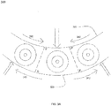
- FIG. 3A is a cross-sectional view of conventional optic fiber ribbon cable in a bending position. Referring to FIG. 3A , when the conventional optic fiber ribbon 300 is bent from the sides of the bottom side 320 towards the top side 315 of the ribbon as illustrated in FIG.
- center pointing compression forces 330 will be exerted on the top side 315
- peripheral-pointing tension forces 340 will be exerted on the bottom side 320A.
- the compression forces 330 and tension forces 340 also interact, converging and concentrating on breaking points D's where the ribbon matrix is most prone to be broken.
- the ribbon matrix may become broken or otherwise damaged if the force is intense or persists.
- the present invention proposes the curved top side to reduce the tension and compression forces when bent as illustrated in FIG. 3 .
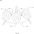
- FIG. 3B is a cross-sectional view of the optic fiber ribbon in a bending position according to a preferred embodiment of the present invention.
- the ribbon 100 is in a bending position.
- the fiber ribbon 100 is bent from the sides of the bottom side 120 towards the top side 115 of the ribbon as illustrated in FIG. 3B , and/or bent from the top side 115 to the bottom side 120 in the center, center pointing compression forces 330 will be exerted on the top side 115, whereas peripheral-pointing tension forces 340 will be exerted on the bottom side 120.
- center pointing compression forces 330 will be exerted on the top side 115
- peripheral-pointing tension forces 340 will be exerted on the bottom side 120.
- bending gaps 240 between the neighboring waveforms 140 starts are pushed together, along the curvature between the valley points Bs and the peak points Cs of the waveforms 140.
- the curvature provides a guided bending pathway for the bendable ribbon 100.
- the neighboring waveforms 140 are "curled” together.
- the points As on the neighboring waveforms 140 will touch each other.
- the bending gaps 240 are devoid of the materials of the ribbon matrix, resulting in the reduction of the tension and compression forces that would be otherwise created should the space is filled with matrix material as illustrated in FIG. 3A .
- FIG. 3C is a cross-sectional view of the optic fiber ribbon in another bending position according to another preferred embodiment of the present invention.
- the bendable ribbon can be bent in a reverse bend, namely bending in a direction pointing from the curved side 115 to the bottom side 120.
- the reverse bend may be opted by users in consideration of factors such as the formfactor of the waveforms 140.
- the valley point Bs are pressed during a bending action in the direction shown in FIG. 3B . When the point As are touching each other, the valley point Bs are subject to compression, causing strain of on the ribbon.
- the particular curve formed of waveform 140 as further described in connection with FIGs.
- the surface along the arcs from points B to A may all subject to more or less compression causing stress and strain of the ribbon.
- a reverse bend as shown in FIG. 3C maybe more advantages depending on the material and/or manufacturing process of the ribbon matrix.
- the cut from B to B' will open up, further extending the bending gap 240 from B to point B'.
- the additional space in the bending gap 240 in FIG. 3C help reduce the reverse bending curve's diameter for similar amount of strain on the structure of the ribbon matrix.
- the curves of the waveform 140 can be configured of a plurality of curves.
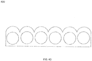
- FIG. 4A-4D illustrates a plurality of cross-sectional view of the curves of the waveform 140 according to embodiments of the present invention.
- FIG. 4A illustrates an optic fiber ribbon with the waveform 140 having a cross-sectional view of a partial circle.
- FIG. 4B illustrates an optic fiber ribbon with the waveform 140 having a cross sectional view of a substantially triangular shape.
- FIG. 4C illustrates an optic fiber ribbon with the waveform 140 having a cross sectional view of a substantially a trapezoid shape.
- FIG. 4D illustrates an optic fiber ribbon with the waveform 140 having a cross sectional view of substantially parabolical curves.
- the above plurality of embodiments are by way of illustration not limitation. Any other cross-sectional shape of the waveforms 140 that having bending gaps between the neighboring domes that allows the optic fiber ribbon to be bent towards the center is within the scope of the present invention.
- FIG. 5A is a conventional multitube single jacket fiber optic cable with ribbons 500A.
- the conventional multitube single jacket fiber optic cable 500A comprises a core 510A, loose tubes 520A and a jacket 530A. Within the loose tubes 520A, a plurality of stacked ribbon 540A is located therein.
- FIG 5A due to the manner the ribbon cables are stacked, there are empty spaces such 550A within the loose tubes and empty spaces between the loose tubes 520A and the cable jacket 530A.
- the empty spaces 550A cannot be used for placing more stacked ribbon cables, because of the dimensional limitation, thereby wasting the space and limiting the total fiber counts that the conventional cable 500A may carry.
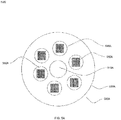
- FIG. 5B illustrates the multitube single jacket fiber optic cable with bendable optic fiber ribbon according to a preferred embodiment of the present invention.
- the fiber optic cable 500B comprises a cable core 510B, a cable jacket 530B and a plurality of bendable optic fiber ribbons 540B.
- the plurality of bendable optic fiber ribbons 540B is arranged in concentric rings layering on top of each other.
- the plurality of bendable optic fiber ribbons 540B are arranged in a spiral manner (not shown), with the plurality of optic fiber ribbon 540B located side-by-side to each other and generally circling the core 510B.
- the plurality of the optic fiber ribbons 540B fills the space between the cable core 510B and the cable jacket 530B in a geometrically tighter manner compared to the conventional cable 500A.
- the wasted spaces such as 550A and 560A as illustrated in FIG. 5A are thus eliminated.
- More ribbon optic cables can be accommodated enhancing the total fiber counts a cable can carry.
Landscapes
- Physics & Mathematics (AREA)
- General Physics & Mathematics (AREA)
- Optics & Photonics (AREA)
- Light Guides In General And Applications Therefor (AREA)
Abstract
Description
- This invention relates to optic fiber ribbon cables. More specifically, the present invention relates to optic fiber ribbon cables with bendable ribbon.
- Optic fiber cables are broadly used to provide fast, high bandwidth data services for telecommunication networks. The optic fibers waveguides or cores are extremely delicate, requiring mechanical protections throughout the length of the cable. Optic fiber ribbon cable is a type of optic fiber cable incorporates a plurality of ribbons for communicating the optical information. Ribbons are formed by disposing a plurality of optic fiber cores in the ribbon matrix. The cores of the ribbons are spaced evenly in a flat array of a common plane directed along the longitude axis of the cable. The ribbon matrix provides structural support and geometrical guide for precisely placing the optic fiber cores evenly across the matrix according to industrial standards. The number of cores within a ribbon may vary, which is usually a number of a power of 2, such as 4, 8, etc.
- Conventionally, a plurality of optic fiber ribbons in the optic fiber ribbon cable are stacked together within loose tubes contained in the cable thereby increasing the total fiber counts the cable may carry. In conventional art, the outer dimensions of ribbon matrices are flat with a flat rectangular shape cross-sectionally. The ribbons are stacked on top of the flat side of each ribbon's matrix. The ribbons stacked together are usually of the same fiber count each, therefore the stacked ribbons usually form a rectangular or square shape cross-sectionally. This design is partially due to the fact that the ribbon matrix has a flat rectangular outer dimension thus the ribbons tend to remain flat on the ribbon's common plane. The ribbons are resistant to bending sideways. When bent, one side of the ribbon matrix will be under tension forces and the other side will be under compression forces. If the bending force is too strong or prolonged, the ribbon matrix will be strained, stress or damaged.
- However, the tubes where the stacked ribbons are contained generally are round, with a circular cross-sectional shape. To accommodate the rectangular or squared stacks of the ribbons, the tubes need to be sufficiently big, with the diameters not smaller than the longer side of the rectangular or the side of the square. Cross-sectionally, the portions of the circle circumscribed by the rectangular or square become wasted space, in the sense that they increase the overall cable dimensions and increase for the same fibre count. For multi-tube ribbon cables, where a plurality of tubes is contained in a cable, the problem is even more acerbated, as there are more spaces between the tubes.
- Therefore, there is a need to provide an optic fiber ribbon cable that increases the total fiber count by utilizing the wasted spaces due to the circumscription of the stack to the tube.
- In an aspect, the present disclosure provides a bendable optic fiber ribbon. The bendable optic fiber ribbon includes a plurality of optic fibers configured for optical communications. In addition, the bendable optic fiber ribbon includes a ribbon matrix. The ribbon matrix includes a first side and a second side. Further, the plurality of optic fibers is disposed in parallel between the first side and the second side along a longitudinal axis of the bendable optic fiber ribbon. The first side includes a plurality of curved surfaces with bending gaps between neighboring curved surface. The bending gaps are configured to reduce at least one of a compression force and a tension force received by the bendable optic fiber ribbon when at least one bending force is applied to said bendable optic fiber ribbon. Each optic fiber of the plurality of optic fibers has a diameter of about 0.200 millimeter. In addition, a distance between center of fiber and peak of the top curved side of the ribbon matrix is about 0.125 millimeter. Further, a distance between bottom flat side of the ribbon matrix and the center of fiber is about 0.115millimeter. Furthermore, the bending gaps between neighboring curved surfaces has an angle of about 6.94 degree.
- A primary object of the present disclosure is to provide a fiber optic cable with a plurality of bendable optic fiber ribbons.
- Another object of this invention is to provide a bendable ribbon conductive to receiving bending forces which can be used in connection with the fiber optic cable with bendable ribbon and increase the fiber count of the cable.
- In an embodiment of the present disclosure, each of the plurality of optic fibers has a diameter of about 250 µm or 200 microns.
- In an embodiment of the present disclosure, a pitch distance in between respective centers of two adjacent optic fibers of the plurality of optic fibers is about 250µm.
- In an embodiment of the present disclosure, the first side of the ribbon matrix includes a top curved side. The top curved side has a cross-sectional shape of periodical waveforms. The shape of the periodical waveforms is selected from a group. The group includes partial circle, triangular, trapezoid and parabolical.
- In an embodiment of the present disclosure, the bendable optic fiber ribbon supports a bi-directional bending when the first side and the second side of the ribbons matrix are curved in shape.
- In an embodiment of the present disclosure, each fiber of the plurality of optic fibers has a diameter of about 0.210 millimeter. In addition, a distance between the center of fiber and peak of the top curved side of the ribbon matrix is about 0.125 millimeter. Further, a distance between the bottom flat side of the ribbon matrix and the center of fiber is about 0.115 millimeter. Furthermore, the bending gaps between neighboring curved surfaces has an angle of about 6.94 degree.
- Having thus described the disclosure in general terms, reference will now be made to the accompanying figures, wherein:
-
FIG. 1 is a perspective view of the bendable ribbon according to a preferred embodiment of the present invention. -
FIG. 2 is close-up cross-sectional view of two neighboring fibers of thebendable ribbon 100 according to a preferred embodiment of the present invention. -
FIG. 3A (prior art) is a cross-sectional view of conventional optic fiber ribbon cable in a bending position. -
FIG. 3B is a cross-sectional view of the optic fiber ribbon in a bending position according to a preferred embodiment of the present invention. -
FIG. 3C is a cross-sectional view of the optic fiber ribbon in another bending position according to another preferred embodiment of the present invention. -
FIG. 4A illustrates an optic fiber ribbon with a waveform according to an embodiment of the present invention. -
FIG. 4B illustrates an optic fiber ribbon with another waveform according to another embodiment of the present invention. -
FIG. 4C illustrates an optic fiber ribbon with still another waveform according to yet another embodiment of the present invention. -
FIG. 4D illustrates an optic fiber ribbon with yet another waveform according to yet another embodiment of the present invention. -
FIG 5A (prior art) is a conventional multitube single jacket fiber optic cable with ribbons. -
FIG. 5B is a multitube single jacket fiber optic cable with bendable optic fiber ribbon according to a preferred embodiment of the present invention. - It should be noted that the accompanying figures are intended to present illustrations of exemplary embodiments of the present disclosure. These figures are not intended to limit the scope of the present disclosure. It should also be noted that accompanying figures are not necessarily drawn to scale.
- For a more complete understanding of the present invention parts, reference is now made to the following descriptions:
- 100. Bendable ribbon.
- 110. Ribbon matrix.
- 115. The curved side.
- 120. The bottom flat side.
- 130. Optic fibers.
- 140. Waveforms.
- 210. Fiber core.
- 220. Cladding.
- 230. Coating.
- 240. Bending gaps.
- 300. The conventional optic fiber ribbon.
- 315. The top side.
- 320. The bottom side.
- 330. The compression forces.
- 340. Tension forces. 500A.
- Conventional cable.
- 510A. Core.
- 520A. loose tubes.
- 530A. Cable jacket.
- 540A. Stacked ribbon.
- 550A. The empty spaces.
- 500B. Fiber optic cable.
- 510B. Cable core.
- 530B. Cable jacket.
- 540B. Bendable optic fiber ribbons.
- The following detailed description is of the best currently contemplated modes of carrying out exemplary embodiments of the invention. The description is not to be taken in a limiting sense, but is made merely for the purpose of illustrating the general principles of the invention.
- Reference will now be made in detail to selected embodiments of the present disclosure in conjunction with accompanying figures. The embodiments described herein are not intended to limit the scope of the disclosure, and the present disclosure should not be construed as limited to the embodiments described. This disclosure may be embodied in different forms without departing from the scope and spirit of the disclosure. It should be understood that the accompanying figures are intended and provided to illustrate embodiments of the disclosure described below and are not necessarily drawn to scale. In the drawings, like numbers refer to like elements throughout, and thicknesses and dimensions of some components may be exaggerated for providing better clarity and ease of understanding.
- It should be noted that the terms "first", "second", and the like, herein do not denote any order, ranking, quantity, or importance, but rather are used to distinguish one element from another. Further, the terms "a" and "an" herein do not denote a limitation of quantity, but rather denote the presence of at least one of the referenced item.
-
FIG. 1 is a perspective view of the bendable ribbon according to a preferred embodiment of the present invention. Referring toFIG. 1 ,bendable ribbon 100 comprises aribbon matrix 110, wherein a plurality ofoptic fibers 130 is disposed in parallel between a first side and a second side along the longitude axis of thebendable ribbon 100. Theribbon matrix 110 provides structural support and geometrical guide for precisely placing the plurality of optic fibers evenly across the matrix according to industrial standards. The number of the optic fibers within theribbon matrix 110 may vary, which is usually a number of power of 2, such as 4, 8, etc. - The
ribbon matrix 110 comprises the first side and the second side. The first side is a topcurved side 115 and the second side is a bottomflat side 120. The topcurved side 115 has a cross-sectional shape of aperiodical waveform 140. The specific shape of thewaveforms 140 can be configured to a variety of waveforms as will be further described in the present invention below. According to the preferred embodiment of the present invention, each of thewaveforms 140 is formed over a single fiber with the optic fiber located in the center of the waveform. As such, each optic fiber of the plurality ofoptic fibers 130 is still sufficiently protected by the ribbon matrix as in prior art. The pitch distance a between the center of neighboring wave forms optic fiber can be configured to any pitch dimension of conventional optic fiber ribbon. As such the bendable ribbons of present invention can be configured to be compatible with any current or future optic fiber ribbon connectors. -
FIG. 2 is close-up cross-sectional view of two neighboring optic fibers of thebendable ribbon 100 according to a preferred embodiment of the present invention. Referring toFIG. 2 , each of the neighboring fibers comprises several of layers forming concentric circles, including afiber core 210, acladding 220 wrapping around thefiber core 210, and anacrylic coating 230, e.g. soft coating and hard coating, wrapping around thecladding 220. There may be other layers and/or components between and/or around thefiber core 210, cladding 220 andcoating 230 not illustrated herein. It is to be understood by people of ordinary skill of the art that ribbons having more or less layers/components than illustrated herein are within scope of the present invention. According to a preferred invention of the present invention, thefiber core 210 has a diameter of substantially 9 µm, thecladding 220 has an outer surface to center distance of substantially 125 micrometer (µm), and thecoating 230 has an outer surface to center distance of substantially 200-210 micrometer (µm). As illustrated in connection withFIG. 1 , a preferred pitch distance (a) between respective centers of two adjacent optic fibers of the plurality of optic fibers (130) is about 250 µm. - Each optic fiber of the plurality of
optic fibers 130 has a diameter of about 250µm or 200 microns. In an embodiment of the present disclosure, each optic fiber of the plurality of optic fibers may have any suitable diameter. - In addition, the distance between the center of the
optic fiber 130 and peak of the topcurved side 115 of theribbon matrix 110 is about 0.125 millimeter. Further, the distance between the center of theoptic fiber 130 and theflat side 120 of theribbon matrix 110 is about 0.115 millimeter. Furthermore, the bending gaps between neighboring curved surfaces has an angle of about 6.94 degree. - Further referring to
FIG. 2 , points C are the peaks of thewaveforms 140 are, whereas point B is the valley of between the neighboringwaveforms 140. Points A are located on the opposite sides of the surface curves between the peaks C and valley B of eachwaveform 140. As will be further illustrated below, when the ribbon is bent, the points A on the neighboring waveforms will be closing in to each other across thebending gap 240 in between them, which results in the reduction of structural forces that work to break the ribbon with matrix that do not have thebending gap 240. Alternatively, theribbon 100 further includes a cut on the ribbon matrix from point B to B'. When the ribbon is not bent or bend from a direction pointing from thebottom side 120 to thecurved side 115, the cut between B and B' remain closed. However, when the ribbon is bent from thecurved side 115 to thebottom side 120, the cut from B to B' will open up, further extending thebending gap 240 to the point B' as illustrated inFIG. 3C below. - Conventional ribbons may have markings to be labeled or printed on the outside of the ribbon matrix. With a
curved side 115, printing or labeling on that side may not be feasible or have a corrugated look hard to read if marked on this side. According to a preferred embodiment of the present invention, the bottomflat side 120 provides a planer side for labeling, printing and other marking means as conventional ribbons. In this regard, the present invention supports cable identification of conventional printing means. Furthermore, the bottomflat side 120 also provides a basis plane during heat stripping and splicing, providing convenience in operations for technicians. As such, the preferred invention supports a bending from the bottomflat side 120 to thecurved side 115. According to another embodiment of the present invention, when marking is not a concern or improved marking oncurved side 115 is sufficient, both thecurved side 115 and thebottom side 120 are curved. This embodiment supports a bi-directional bending to both sides. - The present invention provides advantage over the prior art optic fiber ribbons by having a
curved side 115 that facilitates the bending of the optic fiber ribbons without unduly stress theribbon matrix 110 by reducing the impact of tension and compression forces. This advantage of the present invention will be further illustrated in connection withFIG. 3A (prior art) andFIG. 3B .FIG. 3A (prior art) is a cross-sectional view of conventional optic fiber ribbon cable in a bending position. Referring toFIG. 3A , when the conventionaloptic fiber ribbon 300 is bent from the sides of thebottom side 320 towards thetop side 315 of the ribbon as illustrated inFIG. 3A , and/or bent from thetop side 315 to thebottom side 320 in the center, center pointingcompression forces 330 will be exerted on thetop side 315, whereas peripheral-pointing tension forces 340 will be exerted on the bottom side 320A. The compression forces 330 andtension forces 340 also interact, converging and concentrating on breaking points D's where the ribbon matrix is most prone to be broken. The ribbon matrix may become broken or otherwise damaged if the force is intense or persists. To overcome the disadvantage of the conventional ribbon cable, the present invention proposes the curved top side to reduce the tension and compression forces when bent as illustrated inFIG. 3 . -
FIG. 3B is a cross-sectional view of the optic fiber ribbon in a bending position according to a preferred embodiment of the present invention. Now referring toFIG. 3B , theribbon 100 is in a bending position. Thefiber ribbon 100 is bent from the sides of thebottom side 120 towards thetop side 115 of the ribbon as illustrated inFIG. 3B , and/or bent from thetop side 115 to thebottom side 120 in the center, center pointingcompression forces 330 will be exerted on thetop side 115, whereas peripheral-pointing tension forces 340 will be exerted on thebottom side 120. As illustrated inFIG. 2 andFIG. 3B , in bending position, bendinggaps 240 between the neighboringwaveforms 140 starts are pushed together, along the curvature between the valley points Bs and the peak points Cs of thewaveforms 140. The curvature provides a guided bending pathway for thebendable ribbon 100. During bending, the neighboringwaveforms 140 are "curled" together. The points As on the neighboringwaveforms 140 will touch each other. As illustrated herein, the bendinggaps 240 are devoid of the materials of the ribbon matrix, resulting in the reduction of the tension and compression forces that would be otherwise created should the space is filled with matrix material as illustrated inFIG. 3A . -
FIG. 3C is a cross-sectional view of the optic fiber ribbon in another bending position according to another preferred embodiment of the present invention. Referring toFIG. 3C , the bendable ribbon can be bent in a reverse bend, namely bending in a direction pointing from thecurved side 115 to thebottom side 120. The reverse bend may be opted by users in consideration of factors such as the formfactor of thewaveforms 140. As illustrated inFIG. 3B , the valley point Bs are pressed during a bending action in the direction shown inFIG. 3B . When the point As are touching each other, the valley point Bs are subject to compression, causing strain of on the ribbon. Depending on the particular curve formed ofwaveform 140 as further described in connection withFIGs. 4A-4D , the surface along the arcs from points B to A may all subject to more or less compression causing stress and strain of the ribbon. As such, a reverse bend as shown inFIG. 3C maybe more advantages depending on the material and/or manufacturing process of the ribbon matrix. As shown inFIG. 3C , when the ribbon is bent from thecurved side 115 to thebottom side 120, the cut from B to B' will open up, further extending thebending gap 240 from B to point B'. The additional space in thebending gap 240 inFIG. 3C help reduce the reverse bending curve's diameter for similar amount of strain on the structure of the ribbon matrix. - The curves of the
waveform 140 can be configured of a plurality of curves.FIG. 4A-4D illustrates a plurality of cross-sectional view of the curves of thewaveform 140 according to embodiments of the present invention.FIG. 4A illustrates an optic fiber ribbon with thewaveform 140 having a cross-sectional view of a partial circle.FIG. 4B illustrates an optic fiber ribbon with thewaveform 140 having a cross sectional view of a substantially triangular shape.FIG. 4C illustrates an optic fiber ribbon with thewaveform 140 having a cross sectional view of a substantially a trapezoid shape.FIG. 4D illustrates an optic fiber ribbon with thewaveform 140 having a cross sectional view of substantially parabolical curves. It is to be understood by people of ordinary skill of the art, the above plurality of embodiments are by way of illustration not limitation. Any other cross-sectional shape of thewaveforms 140 that having bending gaps between the neighboring domes that allows the optic fiber ribbon to be bent towards the center is within the scope of the present invention. - The bendable ribbons may be used in connection with ribbon cables to increase the fiber counts of the cable. The optic ribbon cable with bendable ribbon will be illustrated in connection with
FIG. 5A andFIG. 5B .FIG 5A (prior art) is a conventional multitube single jacket fiber optic cable withribbons 500A. The conventional multitube single jacketfiber optic cable 500A comprises acore 510A,loose tubes 520A and ajacket 530A. Within theloose tubes 520A, a plurality ofstacked ribbon 540A is located therein. As is clearly illustrated inFIG 5A , due to the manner the ribbon cables are stacked, there are empty spaces such 550A within the loose tubes and empty spaces between theloose tubes 520A and thecable jacket 530A. Theempty spaces 550A cannot be used for placing more stacked ribbon cables, because of the dimensional limitation, thereby wasting the space and limiting the total fiber counts that theconventional cable 500A may carry. -
FIG. 5B illustrates the multitube single jacket fiber optic cable with bendable optic fiber ribbon according to a preferred embodiment of the present invention. Now referring toFIG. 5B , thefiber optic cable 500B comprises acable core 510B, acable jacket 530B and a plurality of bendableoptic fiber ribbons 540B. The plurality of bendableoptic fiber ribbons 540B is arranged in concentric rings layering on top of each other. Alternatively, the plurality of bendableoptic fiber ribbons 540B are arranged in a spiral manner (not shown), with the plurality ofoptic fiber ribbon 540B located side-by-side to each other and generally circling thecore 510B. As such, the plurality of theoptic fiber ribbons 540B fills the space between thecable core 510B and thecable jacket 530B in a geometrically tighter manner compared to theconventional cable 500A. The wasted spaces such as 550A and 560A as illustrated inFIG. 5A are thus eliminated. More ribbon optic cables can be accommodated enhancing the total fiber counts a cable can carry. - The above descriptions of the embodiments of the present disclosure are provided for demonstration to persons skilled in the art, instead of exhaustively listing all the embodiments or limiting the present disclosure to a single disclosed embodiment. In view of the above, various replacements and variations to the present disclosure are apparent to persons skilled in the art. Therefore, although some alternative embodiments have been discussed in detail, other embodiments are apparent or can be readily derived by a person skilled in the art. The present disclosure is intended to cover all the replacements, modifications and variations to the present disclosure that have been discussed here as well as other embodiments consistent with the spirit and scope of the present disclosure.
- The above specification provides examples of how certain inventive aspects may be put into practice. It will be appreciated that the inventive aspects can be practiced in other ways than those specifically shown and described herein without departing from the spirit and scope of the inventive aspects of the present disclosure.
Claims (7)
- A bendable optic fiber ribbon (100), comprising:a plurality of optic fibers (130) configured for optical communications; anda ribbon matrix (110) comprising a first side and a second side along, wherein the plurality of optic fibers (130) are disposed in parallel between the first side and the second side along a longitudinal axis of the bendable optic fiber ribbon (100),wherein the first side comprises a plurality of curved surfaces with bending gaps between neighboring curved surface, said gaps configured to reduce at least one of a compression force (330) and a tension force (340) received by the bendable optic fiber ribbon (100) when at least one bending force is applied to said bendable optic fiber ribbon (100).
- The bendable optic fiber ribbon (100) as recited in claim 1, wherein each of the plurality of optic fibers (130) has a diameter of about 250 micrometer (µm) or 200 microns.
- The bendable optic fiber ribbon (100) as recited in claim 1 or 2, wherein a pitch distance in between respective centers of two adjacent optic fibers of the plurality of optic fibers (130) is about 250 micrometer (µm).
- The bendable optic fiber ribbon (100) as recited in any preceding claim, wherein the first side of the ribbon matrix (110) comprises a top curved side (115), wherein the top curved side (115) has a cross-sectional shape of periodical waveforms, wherein the shape of the
periodical waveforms is selected from a group, wherein the group comprises partial circle, triangular, trapezoid and parabolical. - The bendable optic fiber ribbon (100) as recited in any preceding claim, wherein the bendable optic fiber ribbon (100) supports a bi-directional bending when the first side and the second side of the ribbon matrix (110) are curved in shape.
- The bendable optic fiber ribbon (100) as recited in any preceding claim, wherein each optic fiber of the plurality of optic fibers (130) has a diameter of about 0.210 millimeter, wherein a distance between center of fiber and peak of top curved side (115) of the ribbon matrix (110) is about 0.125 millimeter, wherein a distance between the center of fiber and bottom flat side (120) of the ribbon matrix (110) is about 0.115 millimeter, wherein the bending gaps between neighboring curved surfaces has an angle of about 6.94 degree.
- A bendable optic fiber ribbon (100), comprising:a plurality of optic fibers (130) configured for optical communications; anda ribbon matrix (110) comprising a first side and a second side along, wherein the plurality of optic fibers (130) is disposed in parallel between the first side and the second side along a longitudinal axis of the bendable optic fiber ribbon (100);wherein the first side comprises a plurality of curved surfaces with bending gaps between neighboring curved surface, said gaps configured to reduce at least one of a compression force (330) and a tension force (340) received by the bendable optic fiber ribbon (100) when at least one bending force is applied to said bendable optic fiber ribbon (100),wherein each optic fiber of the plurality of optic fibers (130) has a diameter of about 0.210 millimeter, wherein a distance between center of fiber and peak of top curved side (115) of the ribbon matrix (110) is about 0.125 millimeter, wherein a distance between the center of fiber and bottom flat side (120) of the ribbon matrix (110) is about 0.115 millimeter, wherein the bending gaps between neighboring curved surfaces has an angle of about 6.94 degree.
Applications Claiming Priority (1)
| Application Number | Priority Date | Filing Date | Title |
|---|---|---|---|
| IN201811020453 | 2018-05-31 |
Publications (2)
| Publication Number | Publication Date |
|---|---|
| EP3575843A1 true EP3575843A1 (en) | 2019-12-04 |
| EP3575843B1 EP3575843B1 (en) | 2025-02-12 |
Family
ID=65635467
Family Applications (1)
| Application Number | Title | Priority Date | Filing Date |
|---|---|---|---|
| EP19159830.9A Active EP3575843B1 (en) | 2018-05-31 | 2019-02-27 | Bendable ribbon for optical fiber ribbon cable |
Country Status (2)
| Country | Link |
|---|---|
| US (1) | US10884206B2 (en) |
| EP (1) | EP3575843B1 (en) |
Citations (5)
| Publication number | Priority date | Publication date | Assignee | Title |
|---|---|---|---|---|
| FR2479481A2 (en) * | 1980-03-25 | 1981-10-02 | Silec Liaisons Elec | Unitary fibre=optic cabling, element - has partially cylindrical cable section with alveoli running longitudinally formed along surface |
| CA1135094A (en) * | 1979-05-11 | 1982-11-09 | Charles Martin | Unitary cabling element for manufacturing optical fiber cable elements |
| US5682454A (en) * | 1994-11-21 | 1997-10-28 | Alcatel Cable | Optical-fiber cable |
| US20040146255A1 (en) * | 2002-11-06 | 2004-07-29 | Hiroki Ishikawa | Optical fiber ribbon and optical fiber cable using the same |
| JP5391131B2 (en) * | 2010-04-12 | 2014-01-15 | 古河電気工業株式会社 | Tape core unit and optical fiber cable |
Family Cites Families (7)
| Publication number | Priority date | Publication date | Assignee | Title |
|---|---|---|---|---|
| US4199225A (en) * | 1978-04-07 | 1980-04-22 | Bicc Limited | Optical guides |
| FR2489002A1 (en) * | 1980-08-22 | 1982-02-26 | Transmissions Optiq Cie Lyonna | Multichannel tape for enclosing optical fibre - to be wound about telecommunication cable, to protect fibres during mfr. of armoured cable for underwater use |
| JPH0256510A (en) * | 1988-08-23 | 1990-02-26 | Sumitomo Electric Ind Ltd | Production of tape type coated optical fibers |
| US5039195A (en) * | 1990-05-29 | 1991-08-13 | At&T Bell Laboratories | Composite cable including portions having controlled flexural rigidities |
| WO2009060678A1 (en) * | 2007-11-08 | 2009-05-14 | Fuji Oil Company, Limited | Soy protein gel and method of producing the same |
| JP2012032683A (en) * | 2010-08-02 | 2012-02-16 | Sumitomo Electric Ind Ltd | Optical fiber cable |
| JP5779940B2 (en) * | 2011-03-30 | 2015-09-16 | 住友電気工業株式会社 | Apparatus and method for manufacturing optical fiber ribbon |
-
2018
- 2018-10-31 US US16/176,294 patent/US10884206B2/en active Active
-
2019
- 2019-02-27 EP EP19159830.9A patent/EP3575843B1/en active Active
Patent Citations (5)
| Publication number | Priority date | Publication date | Assignee | Title |
|---|---|---|---|---|
| CA1135094A (en) * | 1979-05-11 | 1982-11-09 | Charles Martin | Unitary cabling element for manufacturing optical fiber cable elements |
| FR2479481A2 (en) * | 1980-03-25 | 1981-10-02 | Silec Liaisons Elec | Unitary fibre=optic cabling, element - has partially cylindrical cable section with alveoli running longitudinally formed along surface |
| US5682454A (en) * | 1994-11-21 | 1997-10-28 | Alcatel Cable | Optical-fiber cable |
| US20040146255A1 (en) * | 2002-11-06 | 2004-07-29 | Hiroki Ishikawa | Optical fiber ribbon and optical fiber cable using the same |
| JP5391131B2 (en) * | 2010-04-12 | 2014-01-15 | 古河電気工業株式会社 | Tape core unit and optical fiber cable |
Also Published As
| Publication number | Publication date |
|---|---|
| US10884206B2 (en) | 2021-01-05 |
| US20190369342A1 (en) | 2019-12-05 |
| EP3575843B1 (en) | 2025-02-12 |
Similar Documents
| Publication | Publication Date | Title |
|---|---|---|
| EP3330760B1 (en) | Optical fiber cable | |
| US6636673B2 (en) | Fiber optic ribbon interconnects and breakout cables | |
| EP3025174B1 (en) | Fiber optic ribbon | |
| EP3432047A1 (en) | Round and small diameter optical cables with a ribbon-like optical fiber structure | |
| JP5117519B2 (en) | Optical fiber ribbon and optical fiber cable | |
| CN113311535B (en) | Optical fiber ribbon and optical fiber cable | |
| EP3800493A1 (en) | Flexible central tube ribbon optical fiber cable | |
| EP3751322B1 (en) | High density optical fibre ribbon stack | |
| CN117724212A (en) | Optical cable and optical cable with spliced components and optical-electrical hybrid cable | |
| EP3783410A1 (en) | Flexible central tube ribbon optical fiber cable | |
| US11886026B2 (en) | Optical fiber ribbon, optical fiber cable, and connector-equipped optical fiber cord | |
| US20200026016A1 (en) | High density, low bend loss optical fiber ribbon cable | |
| EP3575843B1 (en) | Bendable ribbon for optical fiber ribbon cable | |
| US11125962B2 (en) | Rollable optical fiber ribbon with colour line marking | |
| EP0881513B1 (en) | Optical fiber cable | |
| US11971592B2 (en) | Cable having ribbon stack in a hexagonal arrangement | |
| US20190179094A1 (en) | Hinged optical fiber ribbon moveable between aligned and collapsed positions | |
| JP2001350069A (en) | Fiber optic cable | |
| US20250067948A1 (en) | Optical fiber assembly and optical cable | |
| US11119289B2 (en) | Formfitting loose tube with elastic deformation for optic fiber cables | |
| JP3373909B2 (en) | Fiber optic cable | |
| HK1254082B (en) | Optical fiber cable | |
| MXPA96002131A (en) | Grooved nucleus plug cable compa | |
| HK1124396B (en) | Fiber optic cables and methods for forming the same |
Legal Events
| Date | Code | Title | Description |
|---|---|---|---|
| PUAI | Public reference made under article 153(3) epc to a published international application that has entered the european phase |
Free format text: ORIGINAL CODE: 0009012 |
|
| STAA | Information on the status of an ep patent application or granted ep patent |
Free format text: STATUS: THE APPLICATION HAS BEEN PUBLISHED |
|
| AK | Designated contracting states |
Kind code of ref document: A1 Designated state(s): AL AT BE BG CH CY CZ DE DK EE ES FI FR GB GR HR HU IE IS IT LI LT LU LV MC MK MT NL NO PL PT RO RS SE SI SK SM TR |
|
| AX | Request for extension of the european patent |
Extension state: BA ME |
|
| STAA | Information on the status of an ep patent application or granted ep patent |
Free format text: STATUS: REQUEST FOR EXAMINATION WAS MADE |
|
| 17P | Request for examination filed |
Effective date: 20200604 |
|
| RBV | Designated contracting states (corrected) |
Designated state(s): AL AT BE BG CH CY CZ DE DK EE ES FI FR GB GR HR HU IE IS IT LI LT LU LV MC MK MT NL NO PL PT RO RS SE SI SK SM TR |
|
| STAA | Information on the status of an ep patent application or granted ep patent |
Free format text: STATUS: EXAMINATION IS IN PROGRESS |
|
| 17Q | First examination report despatched |
Effective date: 20201106 |
|
| GRAP | Despatch of communication of intention to grant a patent |
Free format text: ORIGINAL CODE: EPIDOSNIGR1 |
|
| STAA | Information on the status of an ep patent application or granted ep patent |
Free format text: STATUS: GRANT OF PATENT IS INTENDED |
|
| INTG | Intention to grant announced |
Effective date: 20240927 |
|
| GRAS | Grant fee paid |
Free format text: ORIGINAL CODE: EPIDOSNIGR3 |
|
| GRAA | (expected) grant |
Free format text: ORIGINAL CODE: 0009210 |
|
| STAA | Information on the status of an ep patent application or granted ep patent |
Free format text: STATUS: THE PATENT HAS BEEN GRANTED |
|
| AK | Designated contracting states |
Kind code of ref document: B1 Designated state(s): AL AT BE BG CH CY CZ DE DK EE ES FI FR GB GR HR HU IE IS IT LI LT LU LV MC MK MT NL NO PL PT RO RS SE SI SK SM TR |
|
| REG | Reference to a national code |
Ref country code: GB Ref legal event code: FG4D |
|
| REG | Reference to a national code |
Ref country code: CH Ref legal event code: EP |
|
| REG | Reference to a national code |
Ref country code: DE Ref legal event code: R096 Ref document number: 602019065676 Country of ref document: DE |
|
| REG | Reference to a national code |
Ref country code: IE Ref legal event code: FG4D |
|
| REG | Reference to a national code |
Ref country code: NL Ref legal event code: MP Effective date: 20250212 |
|
| PG25 | Lapsed in a contracting state [announced via postgrant information from national office to epo] |
Ref country code: RS Free format text: LAPSE BECAUSE OF FAILURE TO SUBMIT A TRANSLATION OF THE DESCRIPTION OR TO PAY THE FEE WITHIN THE PRESCRIBED TIME-LIMIT Effective date: 20250512 |
|
| PG25 | Lapsed in a contracting state [announced via postgrant information from national office to epo] |
Ref country code: FI Free format text: LAPSE BECAUSE OF FAILURE TO SUBMIT A TRANSLATION OF THE DESCRIPTION OR TO PAY THE FEE WITHIN THE PRESCRIBED TIME-LIMIT Effective date: 20250212 |
|
| PG25 | Lapsed in a contracting state [announced via postgrant information from national office to epo] |
Ref country code: PL Free format text: LAPSE BECAUSE OF FAILURE TO SUBMIT A TRANSLATION OF THE DESCRIPTION OR TO PAY THE FEE WITHIN THE PRESCRIBED TIME-LIMIT Effective date: 20250212 |
|
| PG25 | Lapsed in a contracting state [announced via postgrant information from national office to epo] |
Ref country code: ES Free format text: LAPSE BECAUSE OF FAILURE TO SUBMIT A TRANSLATION OF THE DESCRIPTION OR TO PAY THE FEE WITHIN THE PRESCRIBED TIME-LIMIT Effective date: 20250212 |
|
| REG | Reference to a national code |
Ref country code: LT Ref legal event code: MG9D |
|
| PG25 | Lapsed in a contracting state [announced via postgrant information from national office to epo] |
Ref country code: NO Free format text: LAPSE BECAUSE OF FAILURE TO SUBMIT A TRANSLATION OF THE DESCRIPTION OR TO PAY THE FEE WITHIN THE PRESCRIBED TIME-LIMIT Effective date: 20250512 Ref country code: IS Free format text: LAPSE BECAUSE OF FAILURE TO SUBMIT A TRANSLATION OF THE DESCRIPTION OR TO PAY THE FEE WITHIN THE PRESCRIBED TIME-LIMIT Effective date: 20250612 |
|
| PG25 | Lapsed in a contracting state [announced via postgrant information from national office to epo] |
Ref country code: NL Free format text: LAPSE BECAUSE OF FAILURE TO SUBMIT A TRANSLATION OF THE DESCRIPTION OR TO PAY THE FEE WITHIN THE PRESCRIBED TIME-LIMIT Effective date: 20250212 |
|
| PG25 | Lapsed in a contracting state [announced via postgrant information from national office to epo] |
Ref country code: HR Free format text: LAPSE BECAUSE OF FAILURE TO SUBMIT A TRANSLATION OF THE DESCRIPTION OR TO PAY THE FEE WITHIN THE PRESCRIBED TIME-LIMIT Effective date: 20250212 |
|
| PG25 | Lapsed in a contracting state [announced via postgrant information from national office to epo] |
Ref country code: LV Free format text: LAPSE BECAUSE OF FAILURE TO SUBMIT A TRANSLATION OF THE DESCRIPTION OR TO PAY THE FEE WITHIN THE PRESCRIBED TIME-LIMIT Effective date: 20250212 Ref country code: PT Free format text: LAPSE BECAUSE OF FAILURE TO SUBMIT A TRANSLATION OF THE DESCRIPTION OR TO PAY THE FEE WITHIN THE PRESCRIBED TIME-LIMIT Effective date: 20250612 |
|
| PG25 | Lapsed in a contracting state [announced via postgrant information from national office to epo] |
Ref country code: GR Free format text: LAPSE BECAUSE OF FAILURE TO SUBMIT A TRANSLATION OF THE DESCRIPTION OR TO PAY THE FEE WITHIN THE PRESCRIBED TIME-LIMIT Effective date: 20250513 Ref country code: BG Free format text: LAPSE BECAUSE OF FAILURE TO SUBMIT A TRANSLATION OF THE DESCRIPTION OR TO PAY THE FEE WITHIN THE PRESCRIBED TIME-LIMIT Effective date: 20250212 |
|
| REG | Reference to a national code |
Ref country code: AT Ref legal event code: MK05 Ref document number: 1766570 Country of ref document: AT Kind code of ref document: T Effective date: 20250212 |
|
| REG | Reference to a national code |
Ref country code: DE Ref legal event code: R119 Ref document number: 602019065676 Country of ref document: DE |
|
| PG25 | Lapsed in a contracting state [announced via postgrant information from national office to epo] |
Ref country code: SE Free format text: LAPSE BECAUSE OF FAILURE TO SUBMIT A TRANSLATION OF THE DESCRIPTION OR TO PAY THE FEE WITHIN THE PRESCRIBED TIME-LIMIT Effective date: 20250212 |
|
| REG | Reference to a national code |
Ref country code: CH Ref legal event code: PL |
|
| PG25 | Lapsed in a contracting state [announced via postgrant information from national office to epo] |
Ref country code: SM Free format text: LAPSE BECAUSE OF FAILURE TO SUBMIT A TRANSLATION OF THE DESCRIPTION OR TO PAY THE FEE WITHIN THE PRESCRIBED TIME-LIMIT Effective date: 20250212 |
|
| PG25 | Lapsed in a contracting state [announced via postgrant information from national office to epo] |
Ref country code: DK Free format text: LAPSE BECAUSE OF FAILURE TO SUBMIT A TRANSLATION OF THE DESCRIPTION OR TO PAY THE FEE WITHIN THE PRESCRIBED TIME-LIMIT Effective date: 20250212 |
|
| PG25 | Lapsed in a contracting state [announced via postgrant information from national office to epo] |
Ref country code: IT Free format text: LAPSE BECAUSE OF FAILURE TO SUBMIT A TRANSLATION OF THE DESCRIPTION OR TO PAY THE FEE WITHIN THE PRESCRIBED TIME-LIMIT Effective date: 20250212 Ref country code: LU Free format text: LAPSE BECAUSE OF NON-PAYMENT OF DUE FEES Effective date: 20250227 |
|
| PG25 | Lapsed in a contracting state [announced via postgrant information from national office to epo] |
Ref country code: AT Free format text: LAPSE BECAUSE OF FAILURE TO SUBMIT A TRANSLATION OF THE DESCRIPTION OR TO PAY THE FEE WITHIN THE PRESCRIBED TIME-LIMIT Effective date: 20250212 |
|
| PG25 | Lapsed in a contracting state [announced via postgrant information from national office to epo] |
Ref country code: CH Free format text: LAPSE BECAUSE OF NON-PAYMENT OF DUE FEES Effective date: 20250228 |
|
| PG25 | Lapsed in a contracting state [announced via postgrant information from national office to epo] |
Ref country code: CZ Free format text: LAPSE BECAUSE OF FAILURE TO SUBMIT A TRANSLATION OF THE DESCRIPTION OR TO PAY THE FEE WITHIN THE PRESCRIBED TIME-LIMIT Effective date: 20250212 Ref country code: EE Free format text: LAPSE BECAUSE OF FAILURE TO SUBMIT A TRANSLATION OF THE DESCRIPTION OR TO PAY THE FEE WITHIN THE PRESCRIBED TIME-LIMIT Effective date: 20250212 |
|
| PG25 | Lapsed in a contracting state [announced via postgrant information from national office to epo] |
Ref country code: RO Free format text: LAPSE BECAUSE OF FAILURE TO SUBMIT A TRANSLATION OF THE DESCRIPTION OR TO PAY THE FEE WITHIN THE PRESCRIBED TIME-LIMIT Effective date: 20250212 |
|
| PG25 | Lapsed in a contracting state [announced via postgrant information from national office to epo] |
Ref country code: SK Free format text: LAPSE BECAUSE OF FAILURE TO SUBMIT A TRANSLATION OF THE DESCRIPTION OR TO PAY THE FEE WITHIN THE PRESCRIBED TIME-LIMIT Effective date: 20250212 |
|
| REG | Reference to a national code |
Ref country code: BE Ref legal event code: MM Effective date: 20250228 |
|
| PLBE | No opposition filed within time limit |
Free format text: ORIGINAL CODE: 0009261 |
|
| STAA | Information on the status of an ep patent application or granted ep patent |
Free format text: STATUS: NO OPPOSITION FILED WITHIN TIME LIMIT |
|
| PG25 | Lapsed in a contracting state [announced via postgrant information from national office to epo] |
Ref country code: MC Free format text: LAPSE BECAUSE OF FAILURE TO SUBMIT A TRANSLATION OF THE DESCRIPTION OR TO PAY THE FEE WITHIN THE PRESCRIBED TIME-LIMIT Effective date: 20250212 |
|
| PG25 | Lapsed in a contracting state [announced via postgrant information from national office to epo] |
Ref country code: DE Free format text: LAPSE BECAUSE OF NON-PAYMENT OF DUE FEES Effective date: 20250902 |
|
| PG25 | Lapsed in a contracting state [announced via postgrant information from national office to epo] |
Ref country code: FR Free format text: LAPSE BECAUSE OF NON-PAYMENT OF DUE FEES Effective date: 20250412 |
|
| PG25 | Lapsed in a contracting state [announced via postgrant information from national office to epo] |
Ref country code: BE Free format text: LAPSE BECAUSE OF NON-PAYMENT OF DUE FEES Effective date: 20250228 |
|
| PG25 | Lapsed in a contracting state [announced via postgrant information from national office to epo] |
Ref country code: IE Free format text: LAPSE BECAUSE OF NON-PAYMENT OF DUE FEES Effective date: 20250227 |
|
| 26N | No opposition filed |
Effective date: 20251113 |
|
| PGFP | Annual fee paid to national office [announced via postgrant information from national office to epo] |
Ref country code: GB Payment date: 20260206 Year of fee payment: 8 |
|
| PG25 | Lapsed in a contracting state [announced via postgrant information from national office to epo] |
Ref country code: CY Free format text: LAPSE BECAUSE OF FAILURE TO SUBMIT A TRANSLATION OF THE DESCRIPTION OR TO PAY THE FEE WITHIN THE PRESCRIBED TIME-LIMIT Effective date: 20250212 |
|
| PG25 | Lapsed in a contracting state [announced via postgrant information from national office to epo] |
Ref country code: LT Free format text: LAPSE BECAUSE OF FAILURE TO SUBMIT A TRANSLATION OF THE DESCRIPTION OR TO PAY THE FEE WITHIN THE PRESCRIBED TIME-LIMIT Effective date: 20250212 |
|
| PG25 | Lapsed in a contracting state [announced via postgrant information from national office to epo] |
Ref country code: TR Free format text: LAPSE BECAUSE OF FAILURE TO SUBMIT A TRANSLATION OF THE DESCRIPTION OR TO PAY THE FEE WITHIN THE PRESCRIBED TIME-LIMIT Effective date: 20250212 |