EP3575835A1 - Methods and systems performing joint vvaz and avaz inversion - Google Patents
Methods and systems performing joint vvaz and avaz inversion Download PDFInfo
- Publication number
- EP3575835A1 EP3575835A1 EP19305685.0A EP19305685A EP3575835A1 EP 3575835 A1 EP3575835 A1 EP 3575835A1 EP 19305685 A EP19305685 A EP 19305685A EP 3575835 A1 EP3575835 A1 EP 3575835A1
- Authority
- EP
- European Patent Office
- Prior art keywords
- velocity
- angle
- avaz
- azimuth
- seismic
- Prior art date
- Legal status (The legal status is an assumption and is not a legal conclusion. Google has not performed a legal analysis and makes no representation as to the accuracy of the status listed.)
- Granted
Links
Images





Classifications
-
- G—PHYSICS
- G01—MEASURING; TESTING
- G01V—GEOPHYSICS; GRAVITATIONAL MEASUREMENTS; DETECTING MASSES OR OBJECTS; TAGS
- G01V1/00—Seismology; Seismic or acoustic prospecting or detecting
- G01V1/28—Processing seismic data, e.g. for interpretation or for event detection
- G01V1/30—Analysis
-
- G—PHYSICS
- G01—MEASURING; TESTING
- G01V—GEOPHYSICS; GRAVITATIONAL MEASUREMENTS; DETECTING MASSES OR OBJECTS; TAGS
- G01V1/00—Seismology; Seismic or acoustic prospecting or detecting
- G01V1/28—Processing seismic data, e.g. for interpretation or for event detection
- G01V1/30—Analysis
- G01V1/303—Analysis for determining velocity profiles or travel times
-
- G—PHYSICS
- G01—MEASURING; TESTING
- G01V—GEOPHYSICS; GRAVITATIONAL MEASUREMENTS; DETECTING MASSES OR OBJECTS; TAGS
- G01V1/00—Seismology; Seismic or acoustic prospecting or detecting
- G01V1/28—Processing seismic data, e.g. for interpretation or for event detection
- G01V1/30—Analysis
- G01V1/307—Analysis for determining seismic attributes, e.g. amplitude, instantaneous phase or frequency, reflection strength or polarity
-
- G—PHYSICS
- G01—MEASURING; TESTING
- G01V—GEOPHYSICS; GRAVITATIONAL MEASUREMENTS; DETECTING MASSES OR OBJECTS; TAGS
- G01V1/00—Seismology; Seismic or acoustic prospecting or detecting
- G01V1/28—Processing seismic data, e.g. for interpretation or for event detection
- G01V1/36—Effecting static or dynamic corrections on records, e.g. correcting spread; Correlating seismic signals; Eliminating effects of unwanted energy
- G01V1/362—Effecting static or dynamic corrections; Stacking
-
- G—PHYSICS
- G01—MEASURING; TESTING
- G01V—GEOPHYSICS; GRAVITATIONAL MEASUREMENTS; DETECTING MASSES OR OBJECTS; TAGS
- G01V2210/00—Details of seismic processing or analysis
- G01V2210/50—Corrections or adjustments related to wave propagation
- G01V2210/52—Move-out correction
-
- G—PHYSICS
- G01—MEASURING; TESTING
- G01V—GEOPHYSICS; GRAVITATIONAL MEASUREMENTS; DETECTING MASSES OR OBJECTS; TAGS
- G01V2210/00—Details of seismic processing or analysis
- G01V2210/60—Analysis
- G01V2210/62—Physical property of subsurface
- G01V2210/626—Physical property of subsurface with anisotropy
-
- G—PHYSICS
- G01—MEASURING; TESTING
- G01V—GEOPHYSICS; GRAVITATIONAL MEASUREMENTS; DETECTING MASSES OR OBJECTS; TAGS
- G01V2210/00—Details of seismic processing or analysis
- G01V2210/60—Analysis
- G01V2210/63—Seismic attributes, e.g. amplitude, polarity, instant phase
- G01V2210/632—Amplitude variation versus offset or angle of incidence [AVA, AVO, AVI]
Definitions
- the unflattened azimuthal angle stacks are then inverted using VVAz and AVAz jointly at 420, yielding anisotropy orientation and magnitude consistent with velocities and amplitudes 424.
- phase and group angles are also different.
- the phase angle is the angle of the wave-front normal with reference to the symmetry axis, whereas the group or ray angle is the angle along which energy propagates.
- the article entitled, " Weak elastic anisotropy,” by Thomsen, L. published in Geophysics, Vol. 51, No. 10 (October 1986), pp. 1954-1966 , and the article entitled, " Reflection moveout and parameter estimation for horizontal transverse isotropy,” by Tsvankin, I. published in Geophysics, Vol. 62, No. 2 (March-April 1997), pp. 614-629 provide illustration of the difference between phase and group angles in the case of transverse isotropy media with vertical axis (VTI) and with horizontal axis respectively.
- VTI vertical axis
Landscapes
- Engineering & Computer Science (AREA)
- Remote Sensing (AREA)
- Physics & Mathematics (AREA)
- Life Sciences & Earth Sciences (AREA)
- Acoustics & Sound (AREA)
- Environmental & Geological Engineering (AREA)
- Geology (AREA)
- General Life Sciences & Earth Sciences (AREA)
- General Physics & Mathematics (AREA)
- Geophysics (AREA)
- Geophysics And Detection Of Objects (AREA)
Abstract
Description
- Embodiments of the subject matter disclosed herein generally relate to methods and systems for subsurface exploration, and, in particular, to methods and systems that perform a joint velocity-variation-with-azimuth, VVAz, and amplitude-variation-with-azimuth, AVAz, inversion.
- Probing underground formations in search of hydrocarbon and other resources is an ongoing process driven by continually increasing worldwide demand. Seismic surveys are used for exploration, hydrocarbon reservoir field development, and production monitoring (time lapse). In a simplistic view, seismic excitations emerging from an explored underground (or under seafloor) formation are detected by receivers that generate seismic data (e.g., sampled amplitude of a detected seismic excitation, sampling time and position of the receiver). Generated seismic excitations are usually a combination of compression or P-waves (in which the oscillation is parallel with the propagation direction). If the P-waves are detected after travelling through the explored formation, then seismic data is known as PP seismic data. However, the initial P-waves may be partially converted into S-waves inside the explored formation (in which the oscillation is perpendicular to the propagation direction). If the S-waves are detected after traveling through the explored formation, then seismic data is known as PS seismic data.
- The seismic data undergoes a complex multi-phase processing to yield a structural image based on different properties inside the underground formation. In the seismic data, the sought-after structural information is on one hand mixed with noise, and, on the other hand, the result of various phenomena that occur during the seismic excitations' propagation through various layers.
- One physical characteristic of a layer may be anisotropy, which is propagation with different velocities in different directions, and may be due to fractures or stress. The main technologies used to characterize azimuthal anisotropy, whether it is fracture- or stress-induced, from PP seismic data are Velocity-Variation-with-Azimuth (VVAz) and Amplitude-Variation-with-Azimuth (AVAz).
- For VVAz, the seismic data has to be prepared prior to the analysis.
Figure 1 shows a real data example of a Common Offset Common Azimuth (COCA) cube of data with adjacent slices having increasing offset (or incidence angle) from left to right, and for each offset slice, the azimuth is also increasing from left to right. The azimuthal variation in travel-times appears as a sinusoidal distortion more visible at larger offsets. WAz is an azimuthal NMO (normal moveout) correction that flattens the data by removing the azimuthal variation of travel-times. - WAz usually picks visible seismic events resulting in thick intervals of a few hundred milliseconds. Therefore, VVAz is considered a low-resolution method as discussed, for example, in the article entitled, "The sensitivity of seismic waves to the normal and shear compliance of fractures," by Sayers, C. published in SEG Houston 2009 International Exposition and Annual Meeting, pp. 3441-3445, and the article entitled, "Developments in seismic anisotropy: Treating realistic subsurface models in imaging and fracture detection," by Tsvankin, I. and Grechka, V. published in CSEG Recorder 2006 Special Edition. This flattening step produces anisotropy estimates (anisotropy magnitude and orientation) that can be used for anisotropy characterization.
- Once the data is "flattened," the amplitudes can be analyzed at each time sample, as exemplarily illustrated in
Figure 2 . Since AVAz can be studied at the seismic sample resolution (a few milliseconds), it is assumed to have higher resolution than VVAz. AVAz can be solved in different ways, for example: - near or far offset Rüger equation (as described in the article entitled, "Variation of P-wave reflectivity with offset and azimuth in anisotropic media," by Rüger, A. published in Geophysics, Vol. 63, No. 3 (May-June 1998), pp. 935-947,
- azimuthal Fourier Coefficients (as described in the article entitled, "Azimuthal simultaneous elastic inversion for fracture detection," by Downton, J. and Roure, B. published in SEG Denver 2010 Annual Meeting, pp. 263-267), or
- azimuthal statistical moments (as described in the article entitled, "Statistical moments for azimuthal anisotropy characterization," by Roure, B. published in SEG Denver 2014 Annual Meeting, pp. 290-294).
- AVAz has a higher resolution than VVAz, but it is more unstable and it is limited by its non-uniqueness. AVAz has the drawbacks of an inherent 90° ambiguity and of being highly non-linear. AVAz is very demanding on data quality, requiring large incidence angles, as many azimuths as possible and very little noise. AVAz is sensitive to more anisotropy parameters so there is more information to extract from AVAz, but to do so is more complex.
-
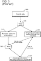
Figure 3 is a flowchart of a conventional method sequentially performing WAz and AVAz. Starting from theseismic data 300, first, WAZ performed at 310 yields flattenedazimuthal angle stacks 312 and anisotropy orientation and magnitude fromvelocities 314. The flattenedazimuthal angle stacks 312 are then used to perform AVAz at 320, yielding anisotropy orientation and magnitude fromamplitudes 324. As suggested by the arrows inFigure 3 , the anisotropy orientation and magnitude fromvelocities 314 may be used as an initial model for AVAz. The anisotropy orientation and magnitude obtained from WAz and AVAz may be difficult to reconcile because they are not consistent in magnitude and orientation. This difference is usually attributed to the different resolutions, but also to the assumption that WAz is more sensitive to stress and AVAz is more sensitive to fractures. - Thus, there is a need to propose methods and systems that overcome the above-described drawbacks and limitations of conventional VVAz and AVAz methods.
- Methods and devices according to various embodiments perform joint WAz and AVAz inversion achieving higher resolution than WAz only, removal of the 90° ambiguity of AVAz only, and reduction of the non-uniqueness of AVAz only (absent additional constraints) by using coupling that VVAz introduces between the inverted properties. The joint VVAz and AVAz inversion uses unflattened data to preserve both the amplitudes and travel-times information, thereby avoiding the stretch and squeeze flattening process, and is less demanding on data quality (i.e., requires fewer azimuth and incidence angles, and reduces AVAz's sensitivity to azimuthal noise).
- According to an embodiment, there is a method for seismic exploration of an underground formation including at least one anisotropic layer. The method includes receiving seismic data acquired by detecting seismic excitations traveling through the underground formation, grouping the seismic data in azimuthal angle stacks, performing a joint VVAz and AVAz inversion using the azimuthal angle stacks to obtain a structural representation of the underground formation, and generating scenarios for exploiting resources in at least one layer of the underground formation based on the structural representation.
- According to another embodiment, there is a system for seismic exploration of an underground formation including at least one anisotropic layer. The system includes seismic data acquisition equipment configured to inject seismic excitations into the underground formation, to detect the seismic excitations that travelled through the underground formation, and to generate the seismic data based on the detected seismic excitations. The system further includes a seismic data processing unit configured to group the seismic data in azimuthal angle stacks, to perform a joint velocity-variation-with-azimuth, VVAz, and amplitude-variation-with-azimuth, AVAz, inversion using the azimuthal angle stacks to obtain a structural representation of the underground formation, and to generate scenarios related to exploiting resources in at least one layer of the underground formation using the structural representation.
- According to yet another embodiment, there is a computer-readable medium storing executable codes which, when executed by a processor, make the processor perform a method of seismic exploration of an underground formation including at least one anisotropic layer. The method includes receiving seismic data acquired by detecting seismic excitations traveling through the underground formation, grouping the seismic data in azimuthal angle stacks, performing a joint VVAz and AVAz inversion using the azimuthal angle stacks to obtain a structural representation of the underground formation, and generating scenarios for exploiting resources in at least one layer of the underground formation based on the structural representation.
- The accompanying drawings, which are incorporated in and constitute a part of the specification, illustrate one or more embodiments and, together with the description, explain these embodiments. In the drawings:
-
Figure 1 illustrates seismic data of a COCA cube; -
Figure 2 is a graph illustrating amplitude variation with azimuth for a given incidence angle and time sample; -
Figure 3 is a flowchart of a conventional method sequentially performing WAz and AVAz; -
Figure 4 is a flowchart of a method performing joint VVAz and AVAz, according to an embodiment; -
Figure 5 illustrates 4D time-shifts in a stratigraphic approach; -
Figure 6 illustrates the use of the stratigraphic grid for multi-component data; -
Figure 7 illustrates the stratigraphic approach for azimuthal anisotropy analysis; -
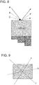
Figure 8 illustrates variation with incidence angle only for the elements inFigure 7 ; -
Figure 9 illustrates azimuth angles for the elements inFigure 7 ; -
Figure 10 is a graph illustrating phase velocity dependence to azimuth angle for different incidence angles measured from the vertical; -
Figure 11 is a graph illustrating group and phase angles variation with azimuth for different incidence angles measured from the vertical; -
Figure 12 is a graph illustrating the difference between phase velocity and group velocity in an HTI medium as a function of incidence angle measured from the vertical for a given azimuth; -
Figure 13 is a flowchart of a method according to an embodiment; and -
Figure 14 is a schematic diagram of a seismic data processing apparatus according to an embodiment. - The following description of the exemplary embodiments refers to the accompanying drawings. The same reference numbers in different drawings identify the same or similar elements. The following detailed description does not limit the invention. Instead, the scope of the invention is defined by the appended claims. The following embodiments are discussed, for simplicity, with regard to the terminology of seismic survey in general, the joint WAz and AVAz inversion being usable for both land and marine seismic data.
- Reference throughout the specification to "one embodiment" or "an embodiment" means that a particular feature, structure or characteristic described in connection with an embodiment is included in at least one embodiment of the subject matter disclosed. Thus, the appearance of the phrases "in one embodiment" or "in an embodiment" in various places throughout the specification is not necessarily referring to the same embodiment. Further, the particular features, structures or characteristics may be combined in any suitable manner in one or more embodiments.
-
Figure 4 is a flowchart of a method performing joint WAz and AVAz inversion, according to an embodiment.Seismic data 400 is grouped in unflattened azimuthal angle stacks at 410. As previously illustrated inFigure 1 , unflatten data has azimuthal variation of travel-times and amplitudes. Azimuthal normal-moveout correction (performed as part of the VVAz analysis) reveals that the travel-times anisotropy increases with the incidence angle. Both corrected and uncorrected traces reveal the amplitude anisotropy increases with incidence angle. The joint VVAz and AVAz inversion works with the unflatten traces and simultaneously translates/inverts the travel-times and amplitude changes in terms of anisotropy properties. - The unflattened azimuthal angle stacks are then inverted using VVAz and AVAz jointly at 420, yielding anisotropy orientation and magnitude consistent with velocities and amplitudes 424.
- The joint VVAz and AVAz inversion uses a stratigraphic grid whose resolution may be as fine as a few ms, thereby greatly enhancing the resolution of the WAz approach. In the stratigraphic grid can coexist multiple vertical axes (time or depth). The use of stratigraphic grid is explained first in the simpler 4D (i.e., surveys acquired in the same area with long time intervals there-between, the earliest survey being known as "base" and the later one(s) as monitor(s)), and PP-PS inversion contexts.
- In 4D, the multiple time axes allow handling production-induced time-shifts by defining a time axis per vintage without aligning the monitor(s) traces to the base traces. Neglecting compaction effects between vintages (i.e., at constant depth), 4D time-shifts (ΔTWT4D) can be related to 4D changes in P-velocity (ΔVp4D) as illustrated in
Figure 5 and mathematically expressed in formula (1) below, where ATWTB is the time-thickness of the layer for the base vintage, ΔTWTM = ATWTB + ΔTWT4D is the time-thickness of the layer for the monitor vintage, VpB is the P-velocity of the base and VpM = VpB + ΔVp4D is the P-velocity of the monitor vintage. The vertical arrows indicate that the PP seismic waves are traveling vertically (i.e., considering post-stack time-shifts only).
- In the case of multi-component (PP-PS) data, the stratigraphic grid handles the difference in travel time between PP and PS waves by defining a time axis for each wave mode without squeezing the PS seismic traces to match PP times. Since the depth is the same in the PP and PS domains, similar to formula (1), formula (2) below links the layer thickness in PS times (ΔTWTPS), in PP times (ΔTWTPP), and the P-to S- velocity ratio Vp/Vs. Here again, post-stack travel times are considered. This correspondence is illustrated in
Figure 6 .
- The same stratigraphic grid approach can be used for azimuthal anisotropy, but the travel-times considered are now pre-stack as non-vertical propagation that varies with incidence angle and azimuth as illustrated in
Figure 7 . The arrows on top of the volume elements A, B and C (the middle element being reference) illustrate the different incidence angles and azimuth angles. The variation with incidence angle only for the elements inFigure 7 is illustrated inFigure 8 , and the azimuth angles thereof are illustrated inFigure 9 . - Unlike the previous cases (i.e., 4D and PP-PS) where the medium was assumed to be isotropic, an anisotropic medium is now considered. As a result, the phase and group velocities become different. AVAz (amplitude) is related to phase velocities, whereas VVAz (travel-time) is related to group velocities. In order to invert jointly velocities/travel-times and amplitudes, the phase velocities extracted from the amplitudes are converted into group velocities.
-
Figure 10 is a graph illustrating the phase velocity as a function of azimuth angle for different incidence angles measured from the vertical. The azimuthal variations increase with incidence angles. The previously cited 1998 Rüger article provides a function linking the phase velocity to incidence angle and azimuth. Another form of the function may also be derived by rotating the stiffness matrix with rotation angles corresponding to the incidence angle and azimuth. - Phase and group angles are also different. The phase angle is the angle of the wave-front normal with reference to the symmetry axis, whereas the group or ray angle is the angle along which energy propagates. The article entitled, "Weak elastic anisotropy," by Thomsen, L. published in Geophysics, Vol. 51, No. 10 (October 1986), pp. 1954-1966, and the article entitled, "Reflection moveout and parameter estimation for horizontal transverse isotropy," by Tsvankin, I. published in Geophysics, Vol. 62, No. 2 (March-April 1997), pp. 614-629, provide illustration of the difference between phase and group angles in the case of transverse isotropy media with vertical axis (VTI) and with horizontal axis respectively.
- The phase angle θ between the phase-velocity vector and the symmetry axis of the medium can be obtained from the group angle ψ (angle between the reflected group-velocity vector and the symmetry axis) using the derivative of the phase velocity Vp with regards to the phase angle θ according to the following formula (3) derived from Tsvankin 1997:

Formula (3) is a non-linear equation easily solved using a few iterations of Newton's method.Figure 11 shows a comparison of group angles ψ (solid lines) converted to phase angles θ (dashed lines) in HTI media as a function of azimuth angle for different incidence angles β (0°, 30°, 60° and 90°) as labeled. - Then, the group velocity Vg may be obtained using the phase velocity Vp, the group and phase angles (ψ and θ respectively) using the following formula (4) derived from Thomsen 1986:

-
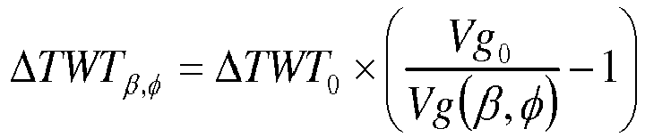
Figure 12 is a graph illustrating the difference between phase velocity and group velocity in an HTI medium. Group velocities are used to model azimuthal travel-times (i.e., pre-stack time-shifts), and phase velocities are used to model the azimuthal amplitudes. The AVAz part of the joint WAz-AVAz inversion can be solved using existing methods in the azimuthal angle stack domain or more efficient AVAz techniques such as Fourier coefficients and statistical moments. - Similar to formula (1) and (2), the difference of travel-time as a function of incidence angle (i.e. group angle in the incidence plane β using 1997 Tsvankin's notation) and azimuth (i.e. the source-receiver azimuth φ) ΔTWTβ,φ is given by formula (5) below, where Vg0 is the reference group velocity, Vg(β,φ) is the direction-dependent group velocity and ΔTWT0 is the reference layer thickness in time (the middle volume element in
Figure 7 ). The stratigraphic grid therefore has a time axis per incidence angle and azimuth as illustrated inFigures 7-9 .
- Joint WAz and AVAz inversion enhances the results of both VVAz and AVAz simultaneously because each method benefits from the other. Several time axes are defined in the stratigraphic grid, their azimuthal and incidence angle variations being controlled by the group velocity derived from the phase velocity. This method is formulated for HTI anisotropy but can easily be extended to orthorhombic anisotropy.
-
Figure 13 is a flowchart ofmethod 1300 according to an embodiment.Method 1300 includes receiving seismic data acquired by detecting seismic excitations traveling through the underground formation at 1310, grouping the seismic data in azimuthal angle stacks at 1320, and performing a joint velocity-variation-with-azimuth, VVAz, and amplitude-variation-with-azimuth, AVAz, inversion using the azimuthal angle stacks to obtain a structural representation of the underground formation at 1330. Various aspects ofsteps - The method further includes generating scenarios for exploiting resources in at least one layer of the underground formation based on the structural representation at 1340. The outcomes of inversions are structural representation of the explored underground formation, which means, in other words, they map properties such as velocity, locating interfaces between different materials, fractures, porosity, etc. These types of information allow evaluation of the presence of hydrocarbons and various minerals and developing exploitation plans (e.g., a path to be followed when drilling to reach the oil or sought-after minerals, to pump liquids when extracting gas by hydraulic fracturing, etc.) called scenarios. The methods presented in this section increase consistency between seismic measurements and, thus, reliability of the structural representations.
- The joint VVAz and AVAz inversion may be performed so as to yield anisotropy's properties consistent with both velocities and amplitudes. The joint VVAz and AVAz inversion may include determining a group velocity and a phase velocity for a layer. The phase velocity may be determined by rotating a stiffness matrix with the incidence angle and the azimuth angle or other methods. Group velocity may be determined using formula (3). Different time axes may be used for different azimuthal angle stacks. A difference in a two-way time-shift may be given by formula (5).
- The above-discussed methods may be implemented in a
computing device 1400 connected to or including seismic data storing equipment as illustrated inFigure 14 . Hardware, firmware, software or a combination thereof may be used to perform the various steps and operations described herein. -
Exemplary computing device 1400 suitable for performing the activities described in the exemplary embodiments may include aserver 1401.Server 1401 may include a central processor (CPU) 1402 coupled to a random-access memory (RAM) 1404 and to a read-only memory (ROM) 1406.ROM 1406 may also be other types of storage media to store programs, such as programmable ROM (PROM), erasable PROM (EPROM), etc.Processor 1402 may communicate with other internal and external components through input/output (I/O)circuitry 1408 and bussing 1410 to provide control signals and the like.Processor 1402 carries out a variety of functions as are known in the art, as dictated by software and/or firmware instructions. -
Server 1401 may also include one or more data storage devices, includinghard drives 1412, CD-ROM drives 1414 and other hardware capable of reading and/or storing information, such as DVD, etc. In one embodiment, software for carrying out the above-discussed steps may be stored and distributed on a CD-ROM orDVD 1416, aUSB storage device 1418 or other form of media capable of portably storing information such as seismic data. These storage media may be inserted into, and read by, devices such as CD-ROM drive 1414,disk drive 1412, etc.Server 1401 may be coupled to adisplay 1420, which may be any type of known display or presentation screen, such as LCD, plasma display, cathode ray tube (CRT), etc. Auser input interface 1422 is provided, including one or more user interface mechanisms such as a mouse, keyboard, microphone, touchpad, touch screen, voice-recognition system, etc. -
Server 1401 may be coupled to other devices, such as sources, detectors, etc. The server may be part of a larger network configuration as in a global area network (GAN) such as theinternet 1428, which allows ultimate connection to various computing devices. - The disclosed exemplary embodiments provide methods for designing or adjusting a survey plan that achieves inline and cross-line seismic data irregularities suitable for compressive sensing reconstruction. It should be understood that this description is not intended to limit the invention. On the contrary, the exemplary embodiments are intended to cover alternatives, modifications and equivalents, which are included in the scope of the invention as defined by the appended claims. Further, in the detailed description of the exemplary embodiments, numerous specific details are set forth in order to provide a comprehensive understanding of the claimed invention. However, one skilled in the art would understand that various embodiments may be practiced without such specific details.
- Although the features and elements of the present exemplary embodiments are described in the embodiments in particular combinations, each feature or element can be used alone without the other features and elements of the embodiments or in various combinations with or without other features and elements disclosed herein.
- This written description uses examples of the subject matter disclosed to enable any person skilled in the art to practice the same, including making and using any devices or systems and performing any incorporated methods. The patentable scope of the subject matter is defined by the claims, and may include other examples that occur to those skilled in the art. Such other examples are intended to be within the scope of the claims.
Claims (14)
- A computer implemented method for seismic exploration of an underground formation including at least one anisotropic layer, the method comprising:receiving (1310) seismic data acquired by detecting seismic excitations traveling through the underground formation;grouping (1320) the seismic data in azimuthal angle stacks;performing (1330) a joint velocity-variation-with-azimuth, VVAz, and amplitude-variation-with-azimuth, AVAz, inversion using the azimuthal angle stacks to obtain a structural representation of the underground formation; andgenerating (1340) scenarios for exploiting resources in at least one layer of the underground formation based on the structural representation.
- The method of claim 1, wherein the joint WAz and AVAz inversion yields anisotropy properties consistent with both velocities and amplitudes.
- The method according to claim 1 or 2, wherein the performing (1330) of the joint WAz and AVAz includes determining a group velocity and a phase velocity for a layer.
- The method of claim 3, wherein the phase velocity is determined by rotating a stiffness matrix with the incidence angle and the azimuth angle.
- The method of claim 3, wherein the group velocity Vg is obtained using the phase velocity according to:

- The method according to any of the preceding claims, wherein the performing of the joint VVAz and AVAz inversion uses different time axes for different azimuthal angle stacks.
- The method of claim 6, wherein a difference in a two-way time-shift ΔTWTβ,φ for an incidence angle, β, and an azimuth angle, Φ, is given by

- A system for seismic exploration of an underground formation including at least one anisotropic layer, the system comprising:seismic data storing equipment configured store seismic data obtained (1310) by injecting seismic excitations into the underground formation, detecting the seismic excitations that travelled through the underground formation, and generating the seismic data based on the detected seismic excitations;a seismic data processing unit configuredto group (1320) the seismic data in azimuthal angle stacks,to perform (1330) a joint velocity-variation-with-azimuth, VVAz, and amplitude-variation-with-azimuth, AVAz, inversion using the azimuthal angle stacks to obtain a structural representation of the underground formation, andto generate (1340) scenarios related to exploiting resources in at least one layer of the underground formation using the structural representation.
- The system of claim 8, wherein the joint WAz and AVAz inversion yields anisotropy's properties consistent with both velocities and amplitudes.
- The system of claim according to claim 8 or 9, wherein the data processing unit includes determining a group velocity and a phase velocity for a layer in the joint VVAz and AVAz inversion.
- The system of claim 10, wherein the data processing unit determines the phase velocity by rotating a stiffness matrix with the incidence angle and the azimuth angle.
- The system of claim 11, wherein the data processing unit uses the phase velocity to obtain the group velocity Vg according to:

- The system according to any of claims 8 to 12, wherein the data processing unit uses different time axes for different azimuthal angle stacks when performing of the joint VVAz and AVAz inversion.
- The system of claim 13, wherein a difference in a two-way time-shift ΔTWTβ,φ for an incidence angle, β, and an azimuth angle, Φ, is given by
Applications Claiming Priority (1)
| Application Number | Priority Date | Filing Date | Title |
|---|---|---|---|
| US15/994,273 US10935681B2 (en) | 2018-05-31 | 2018-05-31 | Methods and systems performing joint VVAz and AVAz inversion |
Publications (2)
| Publication Number | Publication Date |
|---|---|
| EP3575835A1 true EP3575835A1 (en) | 2019-12-04 |
| EP3575835B1 EP3575835B1 (en) | 2021-04-07 |
Family
ID=66998330
Family Applications (1)
| Application Number | Title | Priority Date | Filing Date |
|---|---|---|---|
| EP19305685.0A Active EP3575835B1 (en) | 2018-05-31 | 2019-05-29 | Method and system performing joint vvaz and avaz inversion |
Country Status (4)
| Country | Link |
|---|---|
| US (1) | US10935681B2 (en) |
| EP (1) | EP3575835B1 (en) |
| BR (1) | BR102019010451B1 (en) |
| MX (1) | MX394959B (en) |
Families Citing this family (3)
| Publication number | Priority date | Publication date | Assignee | Title |
|---|---|---|---|---|
| EP3929630B1 (en) * | 2020-06-22 | 2023-04-05 | TotalEnergies OneTech | Computer implemented method for correcting a reservoir model of a reservoir geological formation based on seismic images |
| US11579321B2 (en) | 2020-10-30 | 2023-02-14 | Saudi Arabian Oil Company | Method for characterizing azimuthal anisotropy using cross-dipole sonic data |
| CN113568046B (en) * | 2021-07-28 | 2023-02-03 | 中国海洋石油集团有限公司 | Multi-dimensional information fracture characterization method for fracture azimuth constraint |
Citations (1)
| Publication number | Priority date | Publication date | Assignee | Title |
|---|---|---|---|---|
| US20170322331A1 (en) * | 2014-08-19 | 2017-11-09 | Cgg Services Sas | Joint inversion of compressional and shear seismic data in native time domains |
Family Cites Families (4)
| Publication number | Priority date | Publication date | Assignee | Title |
|---|---|---|---|---|
| US6681184B2 (en) | 2001-05-15 | 2004-01-20 | Input/Output, Inc. | System for estimating azimuthal variations in seismic data |
| SG184002A1 (en) | 2010-03-12 | 2012-10-30 | Cggveritas Services Us Inc | Methods and systems for performing azimuthal simultaneous elastic inversion |
| WO2015092542A2 (en) | 2013-12-16 | 2015-06-25 | Cgg Services Sa | Time-lapse simultaneous inversion of amplitudes and time shifts constrained by pre-computed input maps |
| WO2015145257A2 (en) | 2014-03-28 | 2015-10-01 | Cgg Services Sa | Method and apparatus for characterizing azimuthal anisotropy using statistical moments |
-
2018
- 2018-05-31 US US15/994,273 patent/US10935681B2/en active Active
-
2019
- 2019-05-22 BR BR102019010451-1A patent/BR102019010451B1/en active IP Right Grant
- 2019-05-23 MX MX2019006028A patent/MX394959B/en unknown
- 2019-05-29 EP EP19305685.0A patent/EP3575835B1/en active Active
Patent Citations (1)
| Publication number | Priority date | Publication date | Assignee | Title |
|---|---|---|---|---|
| US20170322331A1 (en) * | 2014-08-19 | 2017-11-09 | Cgg Services Sas | Joint inversion of compressional and shear seismic data in native time domains |
Non-Patent Citations (10)
| Title |
|---|
| DOWNTON, J.ROURE, B.: "Azimuthal simultaneous elastic inversion for fracture detection", SEG DENVER 2010 ANNUAL MEETING, pages 263 - 267 |
| GOODWAY ET AL.: "Combined microseismic and 4D calibrate and confirm surface 3D azimuthal AVO/LMR predictions of completions performance and well production in the Horn River gas shales of NEBC", THE LEADING EDGE, December 2012 (2012-12-01), pages 1502 - 1511 |
| JIE QI* ET AL: "Correcting for VVAz prior to AVAz analysis", SEG TECHNICAL PROGRAM EXPANDED ABSTRACTS 2015, 19 August 2015 (2015-08-19), pages 321 - 325, XP055633833, DOI: 10.1190/segam2015-5877507.1 * |
| ROURE, B.: "Statistical moments for azimuthal anisotropy characterization", SEG DENVER 2014 ANNUAL MEETING, pages 290 - 294 |
| RUGER, A.: "Variation of P-wave reflectivity with offset and azimuth in anisotropic media", GEOPHYSICS, vol. 63, no. 3, May 1998 (1998-05-01), pages 935 - 947, XP002326797, DOI: doi:10.1190/1.1444405 |
| SAYERS, C.: "The sensitivity of seismic waves to the normal and shear compliance of fractures", SEG HOUSTON 2009 INTERNATIONAL EXPOSITION AND ANNUAL MEETING, pages 3441 - 3445 |
| SUBHASHIS MALLICK ET AL: "Azimuthal anisotropy analysis of P-wave seismic data and estimation of the orientation of the in situ stress fields: An example from the Rock-Springs uplift, Wyoming, USA", GEOPHYSICS, vol. 82, no. 2, 1 March 2017 (2017-03-01), US, pages B63 - B77, XP055633830, ISSN: 0016-8033, DOI: 10.1190/geo2015-0268.1 * |
| THOMSEN, L.: "Weak elastic anisotropy", GEOPHYSICS, vol. 51, no. 10, October 1986 (1986-10-01), pages 1954 - 1966, XP002703266, DOI: doi:10.1190/1.1442051 |
| TSVANKIN, I.: "Reflection moveout and parameter estimation for horizontal transverse isotropy", GEOPHYSICS, vol. 62, no. 2, March 1997 (1997-03-01), pages 614 - 629 |
| TSVANKIN, I.GRECHKA, V.: "Developments in seismic anisotropy: Treating realistic subsurface models in imaging and fracture detection", CSEG RECORDER 2006 SPECIAL EDITION |
Also Published As
| Publication number | Publication date |
|---|---|
| EP3575835B1 (en) | 2021-04-07 |
| BR102019010451B1 (en) | 2023-01-31 |
| BR102019010451A2 (en) | 2019-12-10 |
| US20190369279A1 (en) | 2019-12-05 |
| MX394959B (en) | 2025-03-24 |
| MX2019006028A (en) | 2019-12-02 |
| US10935681B2 (en) | 2021-03-02 |
Similar Documents
| Publication | Publication Date | Title |
|---|---|---|
| US10386515B2 (en) | Method and apparatus for analyzing fractures using AVOAz inversion | |
| US8255166B2 (en) | Method of joint inversion of seismic data represented on different time scales | |
| RU2615591C1 (en) | Multiparameter inversion through elastic full-wave inversion (fwi) dependent on shear | |
| EP3358376B1 (en) | Method and apparatus for unambiguously estimating seismic anisotropy parameters | |
| Qiu et al. | Internal structure of the San Jacinto fault zone at Jackass Flat from data recorded by a dense linear array | |
| CN101446645B (en) | A Method of Fluid Determination Using Seismic Fluid Impedance | |
| CA2278441C (en) | Method for fracture detection using multicomponent seismic data | |
| Harrison et al. | Acquisition and analysis of sonic waveforms from a borehole monopole and dipole source for the determination of compressional and shear speeds and their relation to rock mechanical properties and surface seismic data | |
| CA2202168A1 (en) | Reflected shear wave seismic processes | |
| WO2003060560A1 (en) | Layer stripping converted reflected waveforms for dipping fractures | |
| US20140324354A1 (en) | Transmission coefficient method for avo seismic analysis | |
| Shekar et al. | Anisotropic attenuation analysis of crosshole data generated during hydraulic fracturing | |
| EP3575835B1 (en) | Method and system performing joint vvaz and avaz inversion | |
| Li et al. | Practical aspects of AVO modeling | |
| Bush et al. | Paris Basin VSPs: case history establishing combinations of fine-layer (or lithologic) anisotropy and crack anisotropy from modelling shear wavefields near point singularities | |
| Pevzner et al. | Estimation of azimuthal anisotropy from VSP data using multicomponent S-wave velocity analysis | |
| Landrø et al. | Seismic critical-angle reflectometry: A method to characterize azimuthal anisotropy? | |
| Li et al. | Interpreting non‐orthogonal split shear waves for seismic anisotropy in multicomponent VSPS | |
| MacBeth et al. | Examination of a Spectral Method for Measuring the Effects of ANISOTROPY1 | |
| Mahmoudian et al. | A review of angle domain common image gathers | |
| Yang et al. | Inversion of fracture weakness parameters based on 3C vertical seismic profile data—Part I: Horizontal transversely isotropic media composed of a single fracture set in the isotropic background media | |
| Wang et al. | VVAZ vs. AVAZ: practical implementation and comparison of two fracture detection methods | |
| How et al. | Verticalized Sonic Measurements in Deviated Wellbore for Accurate Velocity Modelling and Seismic Well Tie in Offshore Malaysia | |
| Tsvankin et al. | Developments in seismic anisotropy: Treating realistic subsurface models in imaging and fracture detection | |
| Gulati et al. | Overview and introduction to this special section: 3D VSP |
Legal Events
| Date | Code | Title | Description |
|---|---|---|---|
| PUAI | Public reference made under article 153(3) epc to a published international application that has entered the european phase |
Free format text: ORIGINAL CODE: 0009012 |
|
| STAA | Information on the status of an ep patent application or granted ep patent |
Free format text: STATUS: THE APPLICATION HAS BEEN PUBLISHED |
|
| AK | Designated contracting states |
Kind code of ref document: A1 Designated state(s): AL AT BE BG CH CY CZ DE DK EE ES FI FR GB GR HR HU IE IS IT LI LT LU LV MC MK MT NL NO PL PT RO RS SE SI SK SM TR |
|
| AX | Request for extension of the european patent |
Extension state: BA ME |
|
| STAA | Information on the status of an ep patent application or granted ep patent |
Free format text: STATUS: REQUEST FOR EXAMINATION WAS MADE |
|
| 17P | Request for examination filed |
Effective date: 20200526 |
|
| RBV | Designated contracting states (corrected) |
Designated state(s): AL AT BE BG CH CY CZ DE DK EE ES FI FR GB GR HR HU IE IS IT LI LT LU LV MC MK MT NL NO PL PT RO RS SE SI SK SM TR |
|
| GRAP | Despatch of communication of intention to grant a patent |
Free format text: ORIGINAL CODE: EPIDOSNIGR1 |
|
| STAA | Information on the status of an ep patent application or granted ep patent |
Free format text: STATUS: GRANT OF PATENT IS INTENDED |
|
| INTG | Intention to grant announced |
Effective date: 20201218 |
|
| GRAS | Grant fee paid |
Free format text: ORIGINAL CODE: EPIDOSNIGR3 |
|
| GRAA | (expected) grant |
Free format text: ORIGINAL CODE: 0009210 |
|
| STAA | Information on the status of an ep patent application or granted ep patent |
Free format text: STATUS: THE PATENT HAS BEEN GRANTED |
|
| AK | Designated contracting states |
Kind code of ref document: B1 Designated state(s): AL AT BE BG CH CY CZ DE DK EE ES FI FR GB GR HR HU IE IS IT LI LT LU LV MC MK MT NL NO PL PT RO RS SE SI SK SM TR |
|
| REG | Reference to a national code |
Ref country code: GB Ref legal event code: FG4D |
|
| REG | Reference to a national code |
Ref country code: AT Ref legal event code: REF Ref document number: 1380409 Country of ref document: AT Kind code of ref document: T Effective date: 20210415 Ref country code: CH Ref legal event code: EP |
|
| REG | Reference to a national code |
Ref country code: DE Ref legal event code: R096 Ref document number: 602019003784 Country of ref document: DE |
|
| REG | Reference to a national code |
Ref country code: IE Ref legal event code: FG4D |
|
| REG | Reference to a national code |
Ref country code: LT Ref legal event code: MG9D |
|
| REG | Reference to a national code |
Ref country code: NL Ref legal event code: MP Effective date: 20210407 Ref country code: AT Ref legal event code: MK05 Ref document number: 1380409 Country of ref document: AT Kind code of ref document: T Effective date: 20210407 |
|
| REG | Reference to a national code |
Ref country code: NO Ref legal event code: T2 Effective date: 20210407 |
|
| PG25 | Lapsed in a contracting state [announced via postgrant information from national office to epo] |
Ref country code: FI Free format text: LAPSE BECAUSE OF FAILURE TO SUBMIT A TRANSLATION OF THE DESCRIPTION OR TO PAY THE FEE WITHIN THE PRESCRIBED TIME-LIMIT Effective date: 20210407 Ref country code: HR Free format text: LAPSE BECAUSE OF FAILURE TO SUBMIT A TRANSLATION OF THE DESCRIPTION OR TO PAY THE FEE WITHIN THE PRESCRIBED TIME-LIMIT Effective date: 20210407 Ref country code: LT Free format text: LAPSE BECAUSE OF FAILURE TO SUBMIT A TRANSLATION OF THE DESCRIPTION OR TO PAY THE FEE WITHIN THE PRESCRIBED TIME-LIMIT Effective date: 20210407 Ref country code: NL Free format text: LAPSE BECAUSE OF FAILURE TO SUBMIT A TRANSLATION OF THE DESCRIPTION OR TO PAY THE FEE WITHIN THE PRESCRIBED TIME-LIMIT Effective date: 20210407 Ref country code: BG Free format text: LAPSE BECAUSE OF FAILURE TO SUBMIT A TRANSLATION OF THE DESCRIPTION OR TO PAY THE FEE WITHIN THE PRESCRIBED TIME-LIMIT Effective date: 20210707 Ref country code: AT Free format text: LAPSE BECAUSE OF FAILURE TO SUBMIT A TRANSLATION OF THE DESCRIPTION OR TO PAY THE FEE WITHIN THE PRESCRIBED TIME-LIMIT Effective date: 20210407 |
|
| PG25 | Lapsed in a contracting state [announced via postgrant information from national office to epo] |
Ref country code: GR Free format text: LAPSE BECAUSE OF FAILURE TO SUBMIT A TRANSLATION OF THE DESCRIPTION OR TO PAY THE FEE WITHIN THE PRESCRIBED TIME-LIMIT Effective date: 20210708 Ref country code: IS Free format text: LAPSE BECAUSE OF FAILURE TO SUBMIT A TRANSLATION OF THE DESCRIPTION OR TO PAY THE FEE WITHIN THE PRESCRIBED TIME-LIMIT Effective date: 20210807 Ref country code: PL Free format text: LAPSE BECAUSE OF FAILURE TO SUBMIT A TRANSLATION OF THE DESCRIPTION OR TO PAY THE FEE WITHIN THE PRESCRIBED TIME-LIMIT Effective date: 20210407 Ref country code: LV Free format text: LAPSE BECAUSE OF FAILURE TO SUBMIT A TRANSLATION OF THE DESCRIPTION OR TO PAY THE FEE WITHIN THE PRESCRIBED TIME-LIMIT Effective date: 20210407 Ref country code: SE Free format text: LAPSE BECAUSE OF FAILURE TO SUBMIT A TRANSLATION OF THE DESCRIPTION OR TO PAY THE FEE WITHIN THE PRESCRIBED TIME-LIMIT Effective date: 20210407 Ref country code: PT Free format text: LAPSE BECAUSE OF FAILURE TO SUBMIT A TRANSLATION OF THE DESCRIPTION OR TO PAY THE FEE WITHIN THE PRESCRIBED TIME-LIMIT Effective date: 20210809 Ref country code: RS Free format text: LAPSE BECAUSE OF FAILURE TO SUBMIT A TRANSLATION OF THE DESCRIPTION OR TO PAY THE FEE WITHIN THE PRESCRIBED TIME-LIMIT Effective date: 20210407 |
|
| REG | Reference to a national code |
Ref country code: DE Ref legal event code: R119 Ref document number: 602019003784 Country of ref document: DE |
|
| PG25 | Lapsed in a contracting state [announced via postgrant information from national office to epo] |
Ref country code: LU Free format text: LAPSE BECAUSE OF NON-PAYMENT OF DUE FEES Effective date: 20210529 Ref country code: CZ Free format text: LAPSE BECAUSE OF FAILURE TO SUBMIT A TRANSLATION OF THE DESCRIPTION OR TO PAY THE FEE WITHIN THE PRESCRIBED TIME-LIMIT Effective date: 20210407 Ref country code: DK Free format text: LAPSE BECAUSE OF FAILURE TO SUBMIT A TRANSLATION OF THE DESCRIPTION OR TO PAY THE FEE WITHIN THE PRESCRIBED TIME-LIMIT Effective date: 20210407 Ref country code: SM Free format text: LAPSE BECAUSE OF FAILURE TO SUBMIT A TRANSLATION OF THE DESCRIPTION OR TO PAY THE FEE WITHIN THE PRESCRIBED TIME-LIMIT Effective date: 20210407 Ref country code: RO Free format text: LAPSE BECAUSE OF FAILURE TO SUBMIT A TRANSLATION OF THE DESCRIPTION OR TO PAY THE FEE WITHIN THE PRESCRIBED TIME-LIMIT Effective date: 20210407 Ref country code: MC Free format text: LAPSE BECAUSE OF FAILURE TO SUBMIT A TRANSLATION OF THE DESCRIPTION OR TO PAY THE FEE WITHIN THE PRESCRIBED TIME-LIMIT Effective date: 20210407 Ref country code: EE Free format text: LAPSE BECAUSE OF FAILURE TO SUBMIT A TRANSLATION OF THE DESCRIPTION OR TO PAY THE FEE WITHIN THE PRESCRIBED TIME-LIMIT Effective date: 20210407 Ref country code: ES Free format text: LAPSE BECAUSE OF FAILURE TO SUBMIT A TRANSLATION OF THE DESCRIPTION OR TO PAY THE FEE WITHIN THE PRESCRIBED TIME-LIMIT Effective date: 20210407 Ref country code: SK Free format text: LAPSE BECAUSE OF FAILURE TO SUBMIT A TRANSLATION OF THE DESCRIPTION OR TO PAY THE FEE WITHIN THE PRESCRIBED TIME-LIMIT Effective date: 20210407 |
|
| REG | Reference to a national code |
Ref country code: BE Ref legal event code: MM Effective date: 20210531 |
|
| PLBE | No opposition filed within time limit |
Free format text: ORIGINAL CODE: 0009261 |
|
| STAA | Information on the status of an ep patent application or granted ep patent |
Free format text: STATUS: NO OPPOSITION FILED WITHIN TIME LIMIT |
|
| 26N | No opposition filed |
Effective date: 20220110 |
|
| PG25 | Lapsed in a contracting state [announced via postgrant information from national office to epo] |
Ref country code: IE Free format text: LAPSE BECAUSE OF NON-PAYMENT OF DUE FEES Effective date: 20210529 Ref country code: DE Free format text: LAPSE BECAUSE OF NON-PAYMENT OF DUE FEES Effective date: 20211201 |
|
| PG25 | Lapsed in a contracting state [announced via postgrant information from national office to epo] |
Ref country code: IS Free format text: LAPSE BECAUSE OF FAILURE TO SUBMIT A TRANSLATION OF THE DESCRIPTION OR TO PAY THE FEE WITHIN THE PRESCRIBED TIME-LIMIT Effective date: 20210807 Ref country code: FR Free format text: LAPSE BECAUSE OF NON-PAYMENT OF DUE FEES Effective date: 20210607 Ref country code: AL Free format text: LAPSE BECAUSE OF FAILURE TO SUBMIT A TRANSLATION OF THE DESCRIPTION OR TO PAY THE FEE WITHIN THE PRESCRIBED TIME-LIMIT Effective date: 20210407 |
|
| PG25 | Lapsed in a contracting state [announced via postgrant information from national office to epo] |
Ref country code: IT Free format text: LAPSE BECAUSE OF FAILURE TO SUBMIT A TRANSLATION OF THE DESCRIPTION OR TO PAY THE FEE WITHIN THE PRESCRIBED TIME-LIMIT Effective date: 20210407 Ref country code: BE Free format text: LAPSE BECAUSE OF NON-PAYMENT OF DUE FEES Effective date: 20210531 |
|
| REG | Reference to a national code |
Ref country code: CH Ref legal event code: PL |
|
| PG25 | Lapsed in a contracting state [announced via postgrant information from national office to epo] |
Ref country code: LI Free format text: LAPSE BECAUSE OF NON-PAYMENT OF DUE FEES Effective date: 20220531 Ref country code: CH Free format text: LAPSE BECAUSE OF NON-PAYMENT OF DUE FEES Effective date: 20220531 |
|
| PG25 | Lapsed in a contracting state [announced via postgrant information from national office to epo] |
Ref country code: CY Free format text: LAPSE BECAUSE OF FAILURE TO SUBMIT A TRANSLATION OF THE DESCRIPTION OR TO PAY THE FEE WITHIN THE PRESCRIBED TIME-LIMIT Effective date: 20210407 |
|
| P01 | Opt-out of the competence of the unified patent court (upc) registered |
Effective date: 20230530 |
|
| PG25 | Lapsed in a contracting state [announced via postgrant information from national office to epo] |
Ref country code: HU Free format text: LAPSE BECAUSE OF FAILURE TO SUBMIT A TRANSLATION OF THE DESCRIPTION OR TO PAY THE FEE WITHIN THE PRESCRIBED TIME-LIMIT; INVALID AB INITIO Effective date: 20190529 |
|
| PG25 | Lapsed in a contracting state [announced via postgrant information from national office to epo] |
Ref country code: MK Free format text: LAPSE BECAUSE OF FAILURE TO SUBMIT A TRANSLATION OF THE DESCRIPTION OR TO PAY THE FEE WITHIN THE PRESCRIBED TIME-LIMIT Effective date: 20210407 |
|
| PG25 | Lapsed in a contracting state [announced via postgrant information from national office to epo] |
Ref country code: TR Free format text: LAPSE BECAUSE OF FAILURE TO SUBMIT A TRANSLATION OF THE DESCRIPTION OR TO PAY THE FEE WITHIN THE PRESCRIBED TIME-LIMIT Effective date: 20210407 |
|
| PG25 | Lapsed in a contracting state [announced via postgrant information from national office to epo] |
Ref country code: MT Free format text: LAPSE BECAUSE OF FAILURE TO SUBMIT A TRANSLATION OF THE DESCRIPTION OR TO PAY THE FEE WITHIN THE PRESCRIBED TIME-LIMIT Effective date: 20210407 |
|
| PGFP | Annual fee paid to national office [announced via postgrant information from national office to epo] |
Ref country code: GB Payment date: 20250527 Year of fee payment: 7 |
|
| PGFP | Annual fee paid to national office [announced via postgrant information from national office to epo] |
Ref country code: NO Payment date: 20250523 Year of fee payment: 7 |