EP3575772A1 - Hardness tester - Google Patents
Hardness tester Download PDFInfo
- Publication number
- EP3575772A1 EP3575772A1 EP19159237.7A EP19159237A EP3575772A1 EP 3575772 A1 EP3575772 A1 EP 3575772A1 EP 19159237 A EP19159237 A EP 19159237A EP 3575772 A1 EP3575772 A1 EP 3575772A1
- Authority
- EP
- European Patent Office
- Prior art keywords
- body portion
- inclination
- level
- section
- tester
- Prior art date
- Legal status (The legal status is an assumption and is not a legal conclusion. Google has not performed a legal analysis and makes no representation as to the accuracy of the status listed.)
- Withdrawn
Links
- 238000012360 testing method Methods 0.000 claims description 16
- 238000012806 monitoring device Methods 0.000 claims description 9
- 238000004891 communication Methods 0.000 claims description 8
- 230000008859 change Effects 0.000 claims description 3
- 230000006870 function Effects 0.000 abstract description 8
- 238000012545 processing Methods 0.000 abstract description 7
- 230000004044 response Effects 0.000 abstract description 2
- 238000007373 indentation Methods 0.000 description 12
- 238000001514 detection method Methods 0.000 description 6
- 238000012546 transfer Methods 0.000 description 5
- 238000010586 diagram Methods 0.000 description 4
- 230000000694 effects Effects 0.000 description 3
- 230000005484 gravity Effects 0.000 description 3
- 230000007246 mechanism Effects 0.000 description 3
- 238000000034 method Methods 0.000 description 3
- 238000007547 Knoop hardness test Methods 0.000 description 2
- 238000007545 Vickers hardness test Methods 0.000 description 2
- 230000001419 dependent effect Effects 0.000 description 2
- 238000005259 measurement Methods 0.000 description 2
- 230000009467 reduction Effects 0.000 description 2
- 238000007546 Brinell hardness test Methods 0.000 description 1
- 230000008602 contraction Effects 0.000 description 1
- 238000012937 correction Methods 0.000 description 1
- 230000006872 improvement Effects 0.000 description 1
- 238000007689 inspection Methods 0.000 description 1
- 239000004973 liquid crystal related substance Substances 0.000 description 1
- 238000012423 maintenance Methods 0.000 description 1
- 239000000463 material Substances 0.000 description 1
- 239000000203 mixture Substances 0.000 description 1
- 238000012544 monitoring process Methods 0.000 description 1
- 230000008569 process Effects 0.000 description 1
- 230000035945 sensitivity Effects 0.000 description 1
- 238000004154 testing of material Methods 0.000 description 1
- 230000000007 visual effect Effects 0.000 description 1
Images





Classifications
-
- G—PHYSICS
- G01—MEASURING; TESTING
- G01N—INVESTIGATING OR ANALYSING MATERIALS BY DETERMINING THEIR CHEMICAL OR PHYSICAL PROPERTIES
- G01N3/00—Investigating strength properties of solid materials by application of mechanical stress
- G01N3/40—Investigating hardness or rebound hardness
-
- G—PHYSICS
- G01—MEASURING; TESTING
- G01N—INVESTIGATING OR ANALYSING MATERIALS BY DETERMINING THEIR CHEMICAL OR PHYSICAL PROPERTIES
- G01N3/00—Investigating strength properties of solid materials by application of mechanical stress
- G01N3/40—Investigating hardness or rebound hardness
- G01N3/42—Investigating hardness or rebound hardness by performing impressions under a steady load by indentors, e.g. sphere, pyramid
-
- G—PHYSICS
- G01—MEASURING; TESTING
- G01N—INVESTIGATING OR ANALYSING MATERIALS BY DETERMINING THEIR CHEMICAL OR PHYSICAL PROPERTIES
- G01N2203/00—Investigating strength properties of solid materials by application of mechanical stress
- G01N2203/02—Details not specific for a particular testing method
- G01N2203/0202—Control of the test
Definitions
- the present invention relates to hardness testers for measuring hardness of samples based on the size of indentations formed in the samples.
- Typical tests for evaluating hardness of materials include the Vickers hardness test using Vickers indenters (JIS Z 2244) and the Knoop hardness test using Knoop indenters (JIS Z 2251). In these two tests, an indenter is pushed into a sample with a predetermined test force, and the size of an indentation left in the sample is measured from the diagonal length to calculate the hardness of the sample. In such hardness testers, the condition of the sample surface can be visually checked through lenses or can be checked using images captured by a camera and displayed on a monitor (see Patent Literatures 1 and 2).
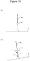
- Figure 10 is a schematic view illustrating the inclination of the body of a tester and forces acting on an indenter 41.
- the indenter 41 In the hardness tester, the indenter needs to be perpendicularly pushed into a surface of a sample from the viewpoint of test accuracy.
- the indenter 41 is attached to the body of the tester via a turret such that an indenter shaft 49 is perpendicular to a surface S of a stage on which the sample is placed.
- the indenter shaft 49 would be inclined with respect to gravity G.
- leg portions In a typical hardness tester, four leg portions, specifically, two each at the front and at the rear, are disposed on the bottom surface of the body of the tester to support the body of the tester.
- the leg portions are extended and contracted with respect to the body of the tester to adjust the level of the body in the front-back and left-right directions. Since it is difficult for users to determine the inclination of the body of the tester based on a visual check, it is recommended that horizontal level adjustment of the body be regularly performed while a precision level using a bubble tube with a sensitivity of 0.05 mm/m or 0.1 mm/m is placed on the stage from which the sample is removed. If the horizontal level is not checked using the precision level, the users would not notice the inclination of the body of the tester, and the tests are likely to be continuously performed while the body of the tester is inclined.
- the accuracy in the level adjustment is affected by differences among individuals.
- the users need to lift up the body of the tester to reach and handle the leg portions, resulting in a complicated work.
- the weight of the body of the tester is heavy (for example, 60 to 80 kg), and thus lifting the body of the tester is a considerable physical burden on the workers.
- the present invention has been devised to solve the above-described problems, and has an object of providing a hardness tester capable of easily adjusting the inclination of the body of the tester.
- a hardness tester for evaluating a characteristic of a sample placed on a stage disposed in a body portion by pushing an indenter into the sample with a predetermined test force, includes a plurality of leg portions disposed on a bottom surface of the body portion, motors each connected to one of the plurality of leg portions to change a length of each of the plurality of leg portions, an inclination detector configured to detect inclination of the body portion, and a control unit including a level adjusting section and a motor control section, the level adjusting section determining a degree of inclination of the body portion based on a value detected by the inclination detector and creating a control signal for the motors to perform level adjustment of the body portion, the motor control section being configured to drive the motors based on the control signal output from the level adjusting section to perform the level adjustment of the body portion.
- control unit displays information about the inclination of the body portion based on the value detected by the inclination detector on a display.
- control unit includes a communication section configured to output the value detected by the inclination detector to an external monitoring device via a network.
- the hardness tester includes the inclination detector, and the degree of inclination of the body portion can be determined based on the value detected by the inclination detector. This enables the inclination of the body portion to be monitored. Consequently, tests in which the body portion is inclined can be prevented from being performed.
- the hardness tester includes the motors configured to change the lengths of the leg portions, and performs the level adjustment of the body portion by creating the control signal for the motors to perform level adjustment of the body portion and by driving the motors based on the control signal.
- commands to drive the motors can be created and output based on the monitored information about the inclination to accurately perform the level adjustment of the body portion.
- the heights of the leg portions can be changed by the motors to allow automatic level adjustment, leading to a reduction in the workload of users.
- the value detected by the inclination detector can be output to the external monitoring device via the network.
- the inclination of the body of the tester can be remotely monitored. This results in an improvement in work efficiency of maintenance and inspection of the tester.
- Figure 1 is a schematic front view of a hardness tester according to the present invention.
- Figure 2 is a perspective view of a body portion 1.
- the hardness tester pushes an indenter into a sample 100 with a predetermined test force and measures the size of indentations left in the sample 100 to perform material testing in which characteristics such as hardness of the sample 100 are evaluated.
- the body portion 1 of the hardness tester includes a base section 52 including a stage 32 on which the sample 100 is placed, a transfer mechanism and an input and display part 39 of the stage 32, and the like, an indentation observation section 51 including an indenter 41, objective lenses 42 and 43, a turret 40, an eyepiece 36, and the like, and a connecting section 53 connecting the base section 52 and the indentation observation section 51.
- the connecting section 53 has an opening 54.
- the base section 52 includes the stage 32 disposed on top of a table 31 and configured to carry the sample 100.
- the stage 32 is configured to transfer the sample 100 in an X direction and in a Y direction orthogonal to the X direction, and is disposed such that the sample carrying surface is parallel to the top surface of the table 31.
- a micrometer knob 33 configured to transfer the sample 100 in the X direction
- a micrometer knob 34 configured to transfer the sample 100 in the Y direction are attached to the stage 32.
- the stage 32 is a manual XY stage moved by operating the knobs 33 and 34.
- the stage 32 may also be an electric XY stage.
- the stage 32 is configured to move up and down in a Z direction orthogonal to the X direction and the Y direction by the effect of a lifting handle 35.
- the input and display part 39 is disposed in the front of the table 31.
- the input and display part 39 is composed of a liquid crystal display panel of a touch panel type, and displays various data such as test conditions and measurement results as well as input keys for inputting the various data.
- the input and display part 39 functions as input means and display means.
- Three leg portions 61 supporting the table 31 and thus supporting the body portion 1 of the hardness tester are disposed on the bottom surface of the table 31.
- One of the three leg portions 61 is disposed adjacent to the front of the table 31 in the vicinity of the middle, and two are disposed adjacent to the rear of the table 31. Note that the two leg portions 61 adjacent to the rear are not illustrated in Figure 1 .
- the body portion 1 is connected with a personal computer 50.
- a main unit 56 of the personal computer 50 is connected with a keyboard 57 and a mouse 58 serving as the input means, a display 55, and a camera 37.
- Control software for displaying images captured by the camera 37 on the display 55 and controlling operations of the body portion 1 of the hardness tester is installed on the main unit 56.
- the eyepiece 36 for visually observing enlarged images of the surface of the sample 100 and a pair of knobs 38 used for moving the gauge during observation of the sample 100 using the eyepiece 36 are disposed in the indentation observation section 51.
- the camera 37 capturing the images of the surface of the sample 100 is installed in the indentation observation section 51.
- the camera 37 sends the captured images of the surface of the sample 100 to the personal computer 50 as digital image data.
- the indentation left in the sample 100 is observed through the image data obtained by the camera 37, and the size is measured.
- the hardness of the surface of the sample 100 is then calculated based on the size of the indentation.
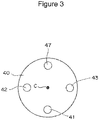
- Figure 3 illustrates the arrangement of the objective lenses and the like supported by the turret 40.
- the indentation observation section 51 includes the indenter 41 and an indenter 47 to be pushed into the sample 100 with fixed test forces, a load mechanism 70 for adding the test forces to the indenters 41 and 47 (see Figure 5 ), the plurality of objective lenses 42 and 43, and the rotatable turret 40 supporting the indenter 41, the objective lenses 42 and 43, and the like (see Figure 1 ).
- the turret 40 rotates about a rotational axis C extending in the vertical direction by operating a knob 46.
- the above-described indenter 41 is, for example, a Vickers indenter used for performing the Vickers hardness test on the sample 100, and the tip of the indenter 41 is a pyramid with a square base.
- the above-described indenter 47 is, for example, a Knoop indenter used for performing the Knoop hardness test on the sample 100, and the tip of the indenter 47 is a pyramid with a rhombus base.
- the shapes of the indenters 41 and 47 may be opposite.
- the indenters 41 and 47 of the hardness tester can be changed to Brinell indenters, which have spherical tips, for the Brinell hardness test.
- Figure 3 illustrates an example of the turret 40 on which the two indenters 41 and 47 and the two objective lenses 42 and 43 having different magnifications are disposed
- the present invention is not limited to this.
- two indenters and four objective lenses having different magnifications may be disposed on the turret.
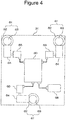
- Figure 4 is a schematic view illustrating the configuration regarding inclination detection and level adjustment of the body portion 1.
- the leg portions 61 supporting the body portion 1 of the hardness tester are attached to the bottom surface of the table 31.
- the body portion 1 is supported by the three leg portions 61 at three points, specifically, one adjacent to the front of the table 31 and one at each end of the table 31 adjacent to the rear.
- the leg portions 61 are composed of so-called adjuster bolts and each include a base 62 brought into contact with the floor and a screw part 63. Rotating the screw parts 63 allows the lengths of the leg portions 61 to be changed and thus the distance between the bottom surface of the table 31 and the mounting surface of the body portion 1 to be adjusted.
- Motors 65 for rotating the screw parts 63 in the leg portions 61 and gearboxes 64 connecting the shafts of the motors 65 and configured to transmit the power of the motors 65 to the screw parts 63 in the leg portions 61 via a plurality of built-in gears are disposed inside the table 31.
- the motors 65 are connected to the respective leg portions 61 via the respective gearboxes 64.
- a level 68 serving as an inclination detector configured to detect the inclination of the body portion 1 is disposed inside the table 31.
- the motors 65 are stepping motors of which rotational angles and rotational speeds can be controlled using pulse signals.
- the level 68 is a so-called digital level capable of measuring numerical values with a resolution of 0.001 mm/m.
- the level 68 is attached to be parallel to the top surface of the table 31 and detects the extent to which the top surface of the table 31 is inclined from the horizontal plane. This corresponds to measurement of the extent of inclination of the sample carrying surface of the stage 32 since the sample carrying surface of the stage 32 is parallel to the top surface of the table 31.
- the top surface of the table 31 serves as the reference plane used for determining whether the body portion 1 is horizontally placed.
- the reference plane is not limited to the above-described example.
- the surface to which the level 68 is attached may be considered as the reference plane, and the reference plane and the sample carrying surface of the stage 32 may be adjusted and secured to be parallel to each other in advance.
- the motors 65 and the level 68 are connected to a tester controller 80.
- the tester controller 80 is a control circuit including memory storing programs, arithmetic and logic units such as an MPU (Micro Processing Unit), and the like arranged on a board.
- the value detected by the level 68 is input to the tester controller 80 and then output to the personal computer 50.
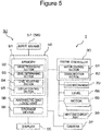
- Figure 5 is a block diagram illustrating a main control system of the hardness tester according to the present invention.
- the hardness tester includes, in the body portion 1, the tester controller 80 configured to control operations of the tester, and the tester controller 80 is connected to the main unit 56 of the personal computer 50 via a communication cable.
- the tester controller 80 and the main unit 56 of the personal computer 50 constitute a control unit of the present invention.
- the tester controller 80 is connected with driving systems of the input and display part 39 and the load mechanism 70.
- a motor control section 81 and a communication section 82 in the tester controller 80 are blocks performing functions and are implemented by circuits mounted on the board.
- the communication section 82 is a device controller compatible with the USB (Universal Serial Bus) data transfer protocol.
- the main unit 56 of the personal computer 50 is connected with the keyboard 57 and the mouse 58 serving as the input means, the display 55, and, furthermore, the camera 37.
- the main unit 56 includes memory 91 such as ROM and RAM, an arithmetic and logic unit 98 such as a CPU (Central Processing Unit), and a storage device 99 connected to one another by buses.
- the memory 91 stores an image processing section 92, a level determining section 93, a level adjusting section 94, and a display control section 95 serving as function modules of programs. Each function is implemented by the arithmetic and logic unit 98 performing the corresponding program.
- the image processing section 92 digitally processes input from the camera 37 and stores image data in the storage device 99.
- the level determining section 93 receives input from the level 68 disposed inside the table 31 of the body portion 1 and determines the degree of inclination (serving as the extent of inclination and expressed by an angle from the horizontal plane) of the body portion 1, that is, the sample carrying surface of the stage 32.
- the level adjusting section 94 creates and outputs signals for controlling the motors 65 connected to the leg portions 61 in response to an operation request from a user via an input unit.
- the display control section 95 controls display conditions such as display of captured images on the display 55 and arrangement of GUI parts on the screen.
- the level adjustment performed by the level adjusting section 94 refers to reduction of the degree of inclination to zero or approximating the degree to zero to the extent possible.
- Figure 6 is a flow chart illustrating the procedure of the level adjustment of the body portion 1.
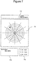
- Figures 7 and 8 are examples of a level adjustment screen displayed on the display 55, operational buttons for inclination adjustment and inclination information being displayed on the screen.
- a user starts the control software on the personal computer 50, selects level adjustment from a menu, and presses a button 72 using the mouse 58 within the level adjustment screen displayed on the display 55. This causes the numerical value from the level 68, that is, information about the current inclination of the body portion 1 to be read into the main unit 56 (step S1).
- the inclination information input from the level 68 is displayed on the display 55 (step S2).
- the user is provided with the inclination information by a black dot plotted on a graphic element 71 mimicking a circular level and numerical values of the heights of the three leg portions 61 displayed in a numerical value display field 74.
- the distance between the black dot plotted in the graphic element 71 and the center of the circle indicates the degree of inclination, and the position of the black dot in the circumferential direction indicates the direction of inclination.
- the inclination information input from the level 68 is used for inclination determination (step S3) performed by the level determining section 93. That is, in a case where it is determined that the numerical value input from the level 68 is greater than a predetermined threshold by executing the program of the level determining section 93, the body portion 1 is determined to be inclined, and a warning message such as "Inclined" is displayed in a result display field 73 as illustrated in Figure 7 (step S4). Since the detection value is output from the level 68 at predetermined intervals, monitoring of the degree of inclination of the body portion 1 according to the inclination determination based on the detection value of the level 68 may be performed at all times.
- step S5 the level adjustment of the body portion 1 is performed.
- the level adjustment of the body portion 1 may be performed without displaying the dialog asking whether to perform the level adjustment when the user presses the button 72 again from among the GUI parts displayed in the display 55 using the mouse 58 while the warning message is displayed in the result display field 73.
- step S5 may be omitted, and the level adjustment may be performed without asking whether to perform the level adjustment.
- correction values of the heights of the respective leg portions 61 are determined, and pulse signals serving as the control signals driving the motors 65 are created based on the inclination information input from the level 68 by the effect of the level adjusting section 94.
- the pulse signals are input to the motor control section 81 of the tester controller 80, each of the motors 65 is driven, and the height of each leg portion 61 is changed.
- the black dot is moved and plotted in the vicinity of the center of the graphic element 71 as illustrated in Figure 8 , the description displayed in the result display field 73 is changed to indicate that the tester is in a normal condition and that a test can be performed.
- the heights of the three leg portions 61 can be changed by the respective motors 65.
- the length of one of the leg portions 61 may be fixed.
- the number of leg portions 61 may be four or more.
- the level determining section 93 and the level adjusting section 94 serving as functional compositions performing the level determination and the level adjustment, respectively, of the body portion 1 are provided for the personal computer 50.
- the level determining section 93 and the level adjusting section 94 may be provided for the tester controller 80, and information about the inclination of the body portion 1 may be displayed in the input and display part 39.
- the tester controller 80 which controls the entire tester, is provided with the function of level adjustment.
- the function of receiving the signal from the level 68 and the control function of driving the motors 65 may be provided for another controller prepared separately from the tester controller 80.
- FIG. 9 is a block diagram illustrating a main control system of a hardness tester according to another embodiment of the present invention.
- the same reference numerals and symbols are used for components similar to those of the embodiment illustrated in Figure 5 , and the detailed descriptions will be omitted.
- a communication section 83 of the tester controller 80 includes a network controller capable of executing protocol processing required for Internet connections in addition to the USB device controller for communicating with the personal computer 50.
- the tester controller 80 in the body portion 1 can be connected with an external monitoring device 101 via the Internet.
- the external monitoring device 101 is composed of, for example, a personal computer provided with a display device and an input device.
- Control software for the hardness tester is installed in the external monitoring device 101, and starting the control software enables the acquisition of the detection value of the level 68 via the Internet and display of the inclination information as illustrated in Figures 7 and 8 on the display device of the external monitoring device 101.
- the external monitoring device 101 is not necessarily a personal computer and may be a combination of a computer (server), connected with a network acquiring the inclination information via the Internet and providing the control software for the hardness tester together with the inclination information, and a communication terminal provided with a display device.
- the inclination information, software package, and the like are supplied to the terminal provided with the display device such as a personal computer or a tablet terminal via the Internet, and the inclination information as illustrated in Figures 7 and 8 is displayed on the display device, allowing the user to monitor the inclination of the body of the tester.
Landscapes
- Physics & Mathematics (AREA)
- Health & Medical Sciences (AREA)
- Life Sciences & Earth Sciences (AREA)
- Chemical & Material Sciences (AREA)
- Analytical Chemistry (AREA)
- Biochemistry (AREA)
- General Health & Medical Sciences (AREA)
- General Physics & Mathematics (AREA)
- Immunology (AREA)
- Pathology (AREA)
- Investigating Strength Of Materials By Application Of Mechanical Stress (AREA)
Abstract
Problem to be Solved
To provide a hardness tester capable of easily adjusting the inclination of the body of the tester.
Solution
An image processing section 92, a level determining section 93, a level adjusting section 94, and a display control section 95 serving as function modules of programs are stored in memory 91 of a main unit 56 of a personal computer 50. The level determining section 93 receives input from a level 68 disposed inside a table of a body portion 1 and determines the degree of inclination of the body portion 1. The level adjusting section 94 creates and outputs signals for driving motors 65 connected to leg portions 61 in response to an operation request from a user via an input unit.
Description
- The present invention relates to hardness testers for measuring hardness of samples based on the size of indentations formed in the samples.
- Typical tests for evaluating hardness of materials include the Vickers hardness test using Vickers indenters (JIS Z 2244) and the Knoop hardness test using Knoop indenters (JIS Z 2251). In these two tests, an indenter is pushed into a sample with a predetermined test force, and the size of an indentation left in the sample is measured from the diagonal length to calculate the hardness of the sample. In such hardness testers, the condition of the sample surface can be visually checked through lenses or can be checked using images captured by a camera and displayed on a monitor (see
Patent Literatures 1 and 2). -
-
Patent Literature 1
Japanese Patent Laid-Open No.2015-158478 -
Patent Literature 2
Japanese Patent Laid-Open No.2005-121416 -
Figure 10 is a schematic view illustrating the inclination of the body of a tester and forces acting on anindenter 41. - In the hardness tester, the indenter needs to be perpendicularly pushed into a surface of a sample from the viewpoint of test accuracy. Thus, as illustrated in
Figure 10 , theindenter 41 is attached to the body of the tester via a turret such that anindenter shaft 49 is perpendicular to a surface S of a stage on which the sample is placed. On the other hand, if the body of the hardness tester is inclined, theindenter shaft 49 would be inclined with respect to gravity G. That is, even when theindenter shaft 49 is perpendicular to the surface S of the stage, the direction along which test force acts does not correspond to the direction of gravity G, and gravity G acting on theindenter 41 is decomposed into a component L in a direction along which the indenter shaft extends and a component V perpendicular to the direction along which the indenter shaft extends (seeFigure 10(b) ). If tests are continuously performed while the body of the tester is inclined, stress in directions other than the direction along which the indenter shaft extends continuously acts on theindenter 41 and theindenter shaft 49, and theindenter shaft 49, which is perpendicular to the surface S of the stage, would be inclined. As a result, the shape of the indentation left when theindenter 41 is pushed into the sample would be affected, leading to poor test accuracy. - In a typical hardness tester, four leg portions, specifically, two each at the front and at the rear, are disposed on the bottom surface of the body of the tester to support the body of the tester. The leg portions are extended and contracted with respect to the body of the tester to adjust the level of the body in the front-back and left-right directions. Since it is difficult for users to determine the inclination of the body of the tester based on a visual check, it is recommended that horizontal level adjustment of the body be regularly performed while a precision level using a bubble tube with a sensitivity of 0.05 mm/m or 0.1 mm/m is placed on the stage from which the sample is removed. If the horizontal level is not checked using the precision level, the users would not notice the inclination of the body of the tester, and the tests are likely to be continuously performed while the body of the tester is inclined.
- Since the users need to manually extend and contract the leg portions to perform level adjustment, the accuracy in the level adjustment is affected by differences among individuals. Moreover, in a case where the extension and contraction of the leg portions are performed manually, the users need to lift up the body of the tester to reach and handle the leg portions, resulting in a complicated work. Furthermore, the weight of the body of the tester is heavy (for example, 60 to 80 kg), and thus lifting the body of the tester is a considerable physical burden on the workers.
- The present invention has been devised to solve the above-described problems, and has an object of providing a hardness tester capable of easily adjusting the inclination of the body of the tester.
- In accordance with the invention according to
claim 1, a hardness tester, for evaluating a characteristic of a sample placed on a stage disposed in a body portion by pushing an indenter into the sample with a predetermined test force, includes a plurality of leg portions disposed on a bottom surface of the body portion, motors each connected to one of the plurality of leg portions to change a length of each of the plurality of leg portions, an inclination detector configured to detect inclination of the body portion, and a control unit including a level adjusting section and a motor control section, the level adjusting section determining a degree of inclination of the body portion based on a value detected by the inclination detector and creating a control signal for the motors to perform level adjustment of the body portion, the motor control section being configured to drive the motors based on the control signal output from the level adjusting section to perform the level adjustment of the body portion. - In accordance with the invention according to
claim 2, which is dependent on the hardness tester according toclaim 1, the control unit displays information about the inclination of the body portion based on the value detected by the inclination detector on a display. - In accordance with the invention according to
claim 3, which is dependent on the hardness tester according toclaim 2, the control unit includes a communication section configured to output the value detected by the inclination detector to an external monitoring device via a network. - In accordance with the invention according to
claims 1 to 3, the hardness tester includes the inclination detector, and the degree of inclination of the body portion can be determined based on the value detected by the inclination detector. This enables the inclination of the body portion to be monitored. Consequently, tests in which the body portion is inclined can be prevented from being performed. Moreover, the hardness tester includes the motors configured to change the lengths of the leg portions, and performs the level adjustment of the body portion by creating the control signal for the motors to perform level adjustment of the body portion and by driving the motors based on the control signal. Thus, commands to drive the motors can be created and output based on the monitored information about the inclination to accurately perform the level adjustment of the body portion. Furthermore, the heights of the leg portions can be changed by the motors to allow automatic level adjustment, leading to a reduction in the workload of users. - In accordance with the invention according to
claim 3, the value detected by the inclination detector can be output to the external monitoring device via the network. Thus, the inclination of the body of the tester can be remotely monitored. This results in an improvement in work efficiency of maintenance and inspection of the tester. -
-
Figure 1 is a schematic front view of a hardness tester according to the present invention; -
Figure 2 is a perspective view of abody portion 1 of the hardness tester according to the present invention; -
Figure 3 illustrates the arrangement of objective lenses and the like supported by aturret 40; -
Figure 4 is a schematic view illustrating the configuration regarding inclination detection and level adjustment of thebody portion 1; -
Figure 5 is a block diagram illustrating a main control system of the hardness tester according to the present invention; -
Figure 6 is a flow chart illustrating the procedure of the level adjustment of thebody portion 1; -
Figure 7 is an example of a level adjustment screen displayed on adisplay 55; -
Figure 8 is an example of a level adjustment screen displayed on thedisplay 55; -
Figure 9 is a block diagram illustrating a main control system of a hardness tester according to another embodiment of the present invention; and -
Figure 10 is a schematic view illustrating the inclination of the body of a tester and forces acting on anindenter 41. - Embodiments of the present invention will now be described with reference to the drawings.
Figure 1 is a schematic front view of a hardness tester according to the present invention.Figure 2 is a perspective view of abody portion 1. - The hardness tester pushes an indenter into a
sample 100 with a predetermined test force and measures the size of indentations left in thesample 100 to perform material testing in which characteristics such as hardness of thesample 100 are evaluated. Thebody portion 1 of the hardness tester includes abase section 52 including astage 32 on which thesample 100 is placed, a transfer mechanism and an input anddisplay part 39 of thestage 32, and the like, anindentation observation section 51 including anindenter 41,objective lenses turret 40, aneyepiece 36, and the like, and a connectingsection 53 connecting thebase section 52 and theindentation observation section 51. The connectingsection 53 has anopening 54. - The
base section 52 includes thestage 32 disposed on top of a table 31 and configured to carry thesample 100. Thestage 32 is configured to transfer thesample 100 in an X direction and in a Y direction orthogonal to the X direction, and is disposed such that the sample carrying surface is parallel to the top surface of the table 31. Amicrometer knob 33 configured to transfer thesample 100 in the X direction and amicrometer knob 34 configured to transfer thesample 100 in the Y direction are attached to thestage 32. Thestage 32 is a manual XY stage moved by operating theknobs stage 32 may also be an electric XY stage. Moreover, thestage 32 is configured to move up and down in a Z direction orthogonal to the X direction and the Y direction by the effect of alifting handle 35. - The input and
display part 39 is disposed in the front of the table 31. The input and displaypart 39 is composed of a liquid crystal display panel of a touch panel type, and displays various data such as test conditions and measurement results as well as input keys for inputting the various data. The input and displaypart 39 functions as input means and display means. Threeleg portions 61 supporting the table 31 and thus supporting thebody portion 1 of the hardness tester are disposed on the bottom surface of the table 31. One of the threeleg portions 61 is disposed adjacent to the front of the table 31 in the vicinity of the middle, and two are disposed adjacent to the rear of the table 31. Note that the twoleg portions 61 adjacent to the rear are not illustrated inFigure 1 . - The
body portion 1 is connected with apersonal computer 50. Amain unit 56 of thepersonal computer 50 is connected with akeyboard 57 and amouse 58 serving as the input means, adisplay 55, and acamera 37. Control software for displaying images captured by thecamera 37 on thedisplay 55 and controlling operations of thebody portion 1 of the hardness tester is installed on themain unit 56. - The
eyepiece 36 for visually observing enlarged images of the surface of thesample 100 and a pair ofknobs 38 used for moving the gauge during observation of thesample 100 using theeyepiece 36 are disposed in theindentation observation section 51. Moreover, thecamera 37 capturing the images of the surface of thesample 100 is installed in theindentation observation section 51. Thecamera 37 sends the captured images of the surface of thesample 100 to thepersonal computer 50 as digital image data. The indentation left in thesample 100 is observed through the image data obtained by thecamera 37, and the size is measured. The hardness of the surface of thesample 100 is then calculated based on the size of the indentation. -
Figure 3 illustrates the arrangement of the objective lenses and the like supported by theturret 40. - The
indentation observation section 51 includes theindenter 41 and anindenter 47 to be pushed into thesample 100 with fixed test forces, aload mechanism 70 for adding the test forces to theindenters 41 and 47 (seeFigure 5 ), the plurality ofobjective lenses rotatable turret 40 supporting theindenter 41, theobjective lenses Figure 1 ). Theturret 40 rotates about a rotational axis C extending in the vertical direction by operating aknob 46. - The above-described
indenter 41 is, for example, a Vickers indenter used for performing the Vickers hardness test on thesample 100, and the tip of theindenter 41 is a pyramid with a square base. On the other hand, the above-describedindenter 47 is, for example, a Knoop indenter used for performing the Knoop hardness test on thesample 100, and the tip of theindenter 47 is a pyramid with a rhombus base. The shapes of theindenters indenters Figure 3 illustrates an example of theturret 40 on which the twoindenters objective lenses -
Figure 4 is a schematic view illustrating the configuration regarding inclination detection and level adjustment of thebody portion 1. - The
leg portions 61 supporting thebody portion 1 of the hardness tester are attached to the bottom surface of the table 31. Thebody portion 1 is supported by the threeleg portions 61 at three points, specifically, one adjacent to the front of the table 31 and one at each end of the table 31 adjacent to the rear. Theleg portions 61 are composed of so-called adjuster bolts and each include a base 62 brought into contact with the floor and ascrew part 63. Rotating thescrew parts 63 allows the lengths of theleg portions 61 to be changed and thus the distance between the bottom surface of the table 31 and the mounting surface of thebody portion 1 to be adjusted.Motors 65 for rotating thescrew parts 63 in theleg portions 61 andgearboxes 64 connecting the shafts of themotors 65 and configured to transmit the power of themotors 65 to thescrew parts 63 in theleg portions 61 via a plurality of built-in gears are disposed inside the table 31. Themotors 65 are connected to therespective leg portions 61 via therespective gearboxes 64. Moreover, alevel 68 serving as an inclination detector configured to detect the inclination of thebody portion 1 is disposed inside the table 31. - The
motors 65 are stepping motors of which rotational angles and rotational speeds can be controlled using pulse signals. Furthermore, thelevel 68 is a so-called digital level capable of measuring numerical values with a resolution of 0.001 mm/m. Thelevel 68 is attached to be parallel to the top surface of the table 31 and detects the extent to which the top surface of the table 31 is inclined from the horizontal plane. This corresponds to measurement of the extent of inclination of the sample carrying surface of thestage 32 since the sample carrying surface of thestage 32 is parallel to the top surface of the table 31. In this example, the top surface of the table 31 serves as the reference plane used for determining whether thebody portion 1 is horizontally placed. The reference plane is not limited to the above-described example. The surface to which thelevel 68 is attached may be considered as the reference plane, and the reference plane and the sample carrying surface of thestage 32 may be adjusted and secured to be parallel to each other in advance. - The
motors 65 and thelevel 68 are connected to atester controller 80. Thetester controller 80 is a control circuit including memory storing programs, arithmetic and logic units such as an MPU (Micro Processing Unit), and the like arranged on a board. The value detected by thelevel 68 is input to thetester controller 80 and then output to thepersonal computer 50. -
Figure 5 is a block diagram illustrating a main control system of the hardness tester according to the present invention. - The hardness tester includes, in the
body portion 1, thetester controller 80 configured to control operations of the tester, and thetester controller 80 is connected to themain unit 56 of thepersonal computer 50 via a communication cable. Thetester controller 80 and themain unit 56 of thepersonal computer 50 constitute a control unit of the present invention. Thetester controller 80 is connected with driving systems of the input and displaypart 39 and theload mechanism 70. Moreover, amotor control section 81 and acommunication section 82 in thetester controller 80 are blocks performing functions and are implemented by circuits mounted on the board. In this embodiment, thecommunication section 82 is a device controller compatible with the USB (Universal Serial Bus) data transfer protocol. - The
main unit 56 of thepersonal computer 50 is connected with thekeyboard 57 and themouse 58 serving as the input means, thedisplay 55, and, furthermore, thecamera 37. Themain unit 56 includesmemory 91 such as ROM and RAM, an arithmetic andlogic unit 98 such as a CPU (Central Processing Unit), and astorage device 99 connected to one another by buses. Thememory 91 stores animage processing section 92, alevel determining section 93, alevel adjusting section 94, and adisplay control section 95 serving as function modules of programs. Each function is implemented by the arithmetic andlogic unit 98 performing the corresponding program. Theimage processing section 92 digitally processes input from thecamera 37 and stores image data in thestorage device 99. Thelevel determining section 93 receives input from thelevel 68 disposed inside the table 31 of thebody portion 1 and determines the degree of inclination (serving as the extent of inclination and expressed by an angle from the horizontal plane) of thebody portion 1, that is, the sample carrying surface of thestage 32. Thelevel adjusting section 94 creates and outputs signals for controlling themotors 65 connected to theleg portions 61 in response to an operation request from a user via an input unit. Moreover, thedisplay control section 95 controls display conditions such as display of captured images on thedisplay 55 and arrangement of GUI parts on the screen. Here, the level adjustment performed by thelevel adjusting section 94 refers to reduction of the degree of inclination to zero or approximating the degree to zero to the extent possible. - Operations of the inclination detection and level adjustment of the
body portion 1 in the hardness tester with the above-described structure will now be described.Figure 6 is a flow chart illustrating the procedure of the level adjustment of thebody portion 1.Figures 7 and8 are examples of a level adjustment screen displayed on thedisplay 55, operational buttons for inclination adjustment and inclination information being displayed on the screen. - First, to check the inclination of the
body portion 1, a user starts the control software on thepersonal computer 50, selects level adjustment from a menu, and presses abutton 72 using themouse 58 within the level adjustment screen displayed on thedisplay 55. This causes the numerical value from thelevel 68, that is, information about the current inclination of thebody portion 1 to be read into the main unit 56 (step S1). - The inclination information input from the
level 68 is displayed on the display 55 (step S2). As illustrated inFigure 7 , the user is provided with the inclination information by a black dot plotted on agraphic element 71 mimicking a circular level and numerical values of the heights of the threeleg portions 61 displayed in a numericalvalue display field 74. The distance between the black dot plotted in thegraphic element 71 and the center of the circle indicates the degree of inclination, and the position of the black dot in the circumferential direction indicates the direction of inclination. - The inclination information input from the
level 68 is used for inclination determination (step S3) performed by thelevel determining section 93. That is, in a case where it is determined that the numerical value input from thelevel 68 is greater than a predetermined threshold by executing the program of thelevel determining section 93, thebody portion 1 is determined to be inclined, and a warning message such as "Inclined" is displayed in aresult display field 73 as illustrated inFigure 7 (step S4). Since the detection value is output from thelevel 68 at predetermined intervals, monitoring of the degree of inclination of thebody portion 1 according to the inclination determination based on the detection value of thelevel 68 may be performed at all times. - While the warning message is displayed in the
result display field 73, a dialog asking whether to perform level adjustment is displayed. In a case where the user selects Yes (step S5), the level adjustment of thebody portion 1 is performed (step S6). The level adjustment of thebody portion 1 may be performed without displaying the dialog asking whether to perform the level adjustment when the user presses thebutton 72 again from among the GUI parts displayed in thedisplay 55 using themouse 58 while the warning message is displayed in theresult display field 73. Moreover, step S5 may be omitted, and the level adjustment may be performed without asking whether to perform the level adjustment. - During the level adjustment, correction values of the heights of the
respective leg portions 61 are determined, and pulse signals serving as the control signals driving themotors 65 are created based on the inclination information input from thelevel 68 by the effect of thelevel adjusting section 94. When the pulse signals are input to themotor control section 81 of thetester controller 80, each of themotors 65 is driven, and the height of eachleg portion 61 is changed. When the black dot is moved and plotted in the vicinity of the center of thegraphic element 71 as illustrated inFigure 8 , the description displayed in theresult display field 73 is changed to indicate that the tester is in a normal condition and that a test can be performed. - In the above-described embodiment, the heights of the three
leg portions 61 can be changed by therespective motors 65. However, for example, the length of one of theleg portions 61 may be fixed. Moreover, the number ofleg portions 61 may be four or more. - Yet moreover, in this embodiment, the
level determining section 93 and thelevel adjusting section 94 serving as functional compositions performing the level determination and the level adjustment, respectively, of thebody portion 1 are provided for thepersonal computer 50. However, thelevel determining section 93 and thelevel adjusting section 94 may be provided for thetester controller 80, and information about the inclination of thebody portion 1 may be displayed in the input and displaypart 39. Furthermore, in this embodiment, thetester controller 80, which controls the entire tester, is provided with the function of level adjustment. However, the function of receiving the signal from thelevel 68 and the control function of driving themotors 65 may be provided for another controller prepared separately from thetester controller 80. -
Figure 9 is a block diagram illustrating a main control system of a hardness tester according to another embodiment of the present invention. The same reference numerals and symbols are used for components similar to those of the embodiment illustrated inFigure 5 , and the detailed descriptions will be omitted. - In this embodiment, a
communication section 83 of thetester controller 80 includes a network controller capable of executing protocol processing required for Internet connections in addition to the USB device controller for communicating with thepersonal computer 50. In this embodiment, thetester controller 80 in thebody portion 1 can be connected with anexternal monitoring device 101 via the Internet. - The
external monitoring device 101 is composed of, for example, a personal computer provided with a display device and an input device. Control software for the hardness tester is installed in theexternal monitoring device 101, and starting the control software enables the acquisition of the detection value of thelevel 68 via the Internet and display of the inclination information as illustrated inFigures 7 and8 on the display device of theexternal monitoring device 101. Theexternal monitoring device 101 is not necessarily a personal computer and may be a combination of a computer (server), connected with a network acquiring the inclination information via the Internet and providing the control software for the hardness tester together with the inclination information, and a communication terminal provided with a display device. In this case, the inclination information, software package, and the like are supplied to the terminal provided with the display device such as a personal computer or a tablet terminal via the Internet, and the inclination information as illustrated inFigures 7 and8 is displayed on the display device, allowing the user to monitor the inclination of the body of the tester. -
- 1
- Body portion
- 31
- Table
- 32
- Stage
- 36
- Eyepiece
- 37
- Camera
- 39
- Input and display part
- 40
- Turret
- 41
- Indenter
- 42
- Objective lens
- 43
- Objective lens
- 47
- Indenter
- 49
- Indenter shaft
- 50
- Personal computer
- 51
- Indentation observation section
- 52
- Base section
- 53
- Connecting section
- 54
- Opening
- 55
- Display
- 61
- Leg portion
- 62
- Base
- 63
- Screw part
- 64
- Gearbox
- 65
- Motor
- 68
- Level
- 71
- Graphic element
- 72
- Button
- 73
- Result display field
- 74
- Numerical value display field
- 80
- Tester controller
- 81
- Motor control section
- 82
- Communication section
- 91
- Memory
- 92
- Image processing section
- 93
- Level determining section
- 94
- Level adjusting section
- 95
- Display control section
- 98
- Arithmetic and logic unit
- 99
- Storage device
- 100
- Sample
- 101
- External monitoring device
Claims (3)
- A hardness tester for evaluating a characteristic of a sample placed on a stage disposed in a body portion by pushing an indenter into the sample with a predetermined test force, the hardness tester comprising:a plurality of leg portions disposed on a bottom surface of the body portion;motors each connected to one of the plurality of leg portions to change a length of each of the plurality of leg portions;an inclination detector configured to detect inclination of the body portion; anda control unit including a level adjusting section and a motor control section, the level adjusting section determining a degree of inclination of the body portion based on a value detected by the inclination detector and creating a control signal for the motors to perform level adjustment of the body portion, the motor control section being configured to drive the motors based on the control signal output from the level adjusting section to perform the level adjustment of the body portion.
- The hardness tester according to claim 1, wherein
the control unit displays information about the inclination of the body portion based on the value detected by the inclination detector on a display. - The hardness tester according to claim 2, wherein
the control unit includes a communication section configured to output the value detected by the inclination detector to an external monitoring device via a network.
Applications Claiming Priority (1)
| Application Number | Priority Date | Filing Date | Title |
|---|---|---|---|
| JP2018101382A JP2019207116A (en) | 2018-05-28 | 2018-05-28 | Hardness testing machine |
Publications (1)
| Publication Number | Publication Date |
|---|---|
| EP3575772A1 true EP3575772A1 (en) | 2019-12-04 |
Family
ID=65598448
Family Applications (1)
| Application Number | Title | Priority Date | Filing Date |
|---|---|---|---|
| EP19159237.7A Withdrawn EP3575772A1 (en) | 2018-05-28 | 2019-02-26 | Hardness tester |
Country Status (2)
| Country | Link |
|---|---|
| EP (1) | EP3575772A1 (en) |
| JP (1) | JP2019207116A (en) |
Cited By (2)
| Publication number | Priority date | Publication date | Assignee | Title |
|---|---|---|---|---|
| CN111650067A (en) * | 2020-05-13 | 2020-09-11 | 雅视特科技(杭州)有限公司 | Brinell hardness indentation automatic measurement system and measurement method thereof |
| CN112362453A (en) * | 2020-11-18 | 2021-02-12 | 天长市鸿运仪表电线电缆有限公司 | Flame retarded cable outer wrapping layer performance detection device |
Families Citing this family (2)
| Publication number | Priority date | Publication date | Assignee | Title |
|---|---|---|---|---|
| JP2022082983A (en) * | 2020-11-24 | 2022-06-03 | 株式会社A&Dホロンホールディングス | Mobile terminal device for assisting leveling work of balance |
| CN113554840A (en) * | 2021-07-14 | 2021-10-26 | 中国水利水电第十四工程局有限公司 | Tunnel fire monitoring alarm device |
Citations (8)
| Publication number | Priority date | Publication date | Assignee | Title |
|---|---|---|---|---|
| US3623359A (en) * | 1970-01-19 | 1971-11-30 | Nasa | Penetrometer |
| FR2334096A1 (en) * | 1975-12-02 | 1977-07-01 | M & O Applic Mec Optique | Portable penetrometer for investigating road surfaces - has separate tripod carrying pile driver and guide for element driven into surface of road |
| JP2005121416A (en) | 2003-10-15 | 2005-05-12 | Shimadzu Corp | Indentation type hardness tester |
| JP2006145474A (en) * | 2004-11-24 | 2006-06-08 | Mitsutoyo Corp | Material property evaluation system |
| US20090145196A1 (en) * | 2007-12-07 | 2009-06-11 | Mitutoyo Corporation | Hardness testing instrument and calibration method thereof |
| US20130047712A1 (en) * | 2011-08-31 | 2013-02-28 | Mitutoyo Corporation | Hardness tester |
| JP2015158478A (en) | 2014-01-27 | 2015-09-03 | 株式会社島津製作所 | Hardness testing machine |
| JP2016045168A (en) * | 2014-08-26 | 2016-04-04 | 国立大学法人広島大学 | Balance type texture measuring device |
-
2018
- 2018-05-28 JP JP2018101382A patent/JP2019207116A/en active Pending
-
2019
- 2019-02-26 EP EP19159237.7A patent/EP3575772A1/en not_active Withdrawn
Patent Citations (8)
| Publication number | Priority date | Publication date | Assignee | Title |
|---|---|---|---|---|
| US3623359A (en) * | 1970-01-19 | 1971-11-30 | Nasa | Penetrometer |
| FR2334096A1 (en) * | 1975-12-02 | 1977-07-01 | M & O Applic Mec Optique | Portable penetrometer for investigating road surfaces - has separate tripod carrying pile driver and guide for element driven into surface of road |
| JP2005121416A (en) | 2003-10-15 | 2005-05-12 | Shimadzu Corp | Indentation type hardness tester |
| JP2006145474A (en) * | 2004-11-24 | 2006-06-08 | Mitsutoyo Corp | Material property evaluation system |
| US20090145196A1 (en) * | 2007-12-07 | 2009-06-11 | Mitutoyo Corporation | Hardness testing instrument and calibration method thereof |
| US20130047712A1 (en) * | 2011-08-31 | 2013-02-28 | Mitutoyo Corporation | Hardness tester |
| JP2015158478A (en) | 2014-01-27 | 2015-09-03 | 株式会社島津製作所 | Hardness testing machine |
| JP2016045168A (en) * | 2014-08-26 | 2016-04-04 | 国立大学法人広島大学 | Balance type texture measuring device |
Cited By (2)
| Publication number | Priority date | Publication date | Assignee | Title |
|---|---|---|---|---|
| CN111650067A (en) * | 2020-05-13 | 2020-09-11 | 雅视特科技(杭州)有限公司 | Brinell hardness indentation automatic measurement system and measurement method thereof |
| CN112362453A (en) * | 2020-11-18 | 2021-02-12 | 天长市鸿运仪表电线电缆有限公司 | Flame retarded cable outer wrapping layer performance detection device |
Also Published As
| Publication number | Publication date |
|---|---|
| JP2019207116A (en) | 2019-12-05 |
Similar Documents
| Publication | Publication Date | Title |
|---|---|---|
| US9664733B2 (en) | Probe device for testing electrical characteristics of semiconductor element | |
| US20130042696A1 (en) | Material testing machine | |
| JP2019207116A (en) | Hardness testing machine | |
| JP5998732B2 (en) | Hardness testing machine | |
| JP2017227475A (en) | Hardness testing machine | |
| JP2007312877A (en) | Body measuring device | |
| US9442156B2 (en) | Alignment support device and alignment support method for probe device | |
| JP6248877B2 (en) | Hardness testing machine | |
| JP2018165643A (en) | Hardness testing machine and program | |
| CN210181111U (en) | Resistance measuring device | |
| JP5416234B2 (en) | Method of moving an object to be imaged and probe apparatus using this method | |
| JP6471684B2 (en) | Hardness testing machine | |
| CN110118796B (en) | Non-contact displacement extraction type shrinkage temperature measuring method and device | |
| CN112656363A (en) | Vision detection system and vision detection method | |
| JP2021156681A (en) | Information board abnormality detection system | |
| JP2742640B2 (en) | Automatic crack growth dimension measurement device | |
| JP2012008075A (en) | Physical strength measurement device of object | |
| JPS61168235A (en) | Testing apparatus of bonding strength | |
| JP2012247388A (en) | Hardness testing machine | |
| JP7357272B2 (en) | Information board anomaly detection system | |
| KR102878819B1 (en) | Thickness measuring system capable of analysing thickness deviation of plate structure | |
| JP3217602U (en) | Objective micrometer and hardness tester | |
| KR102885557B1 (en) | Detection Methods and Management System for Infrastructure Failure in concrete pole | |
| JP5563334B2 (en) | Examining table | |
| CN109835503B (en) | Helicopter inclination angle detection device and leveling method |
Legal Events
| Date | Code | Title | Description |
|---|---|---|---|
| PUAI | Public reference made under article 153(3) epc to a published international application that has entered the european phase |
Free format text: ORIGINAL CODE: 0009012 |
|
| AK | Designated contracting states |
Kind code of ref document: A1 Designated state(s): AL AT BE BG CH CY CZ DE DK EE ES FI FR GB GR HR HU IE IS IT LI LT LU LV MC MK MT NL NO PL PT RO RS SE SI SK SM TR |
|
| AX | Request for extension of the european patent |
Extension state: BA ME |
|
| STAA | Information on the status of an ep patent application or granted ep patent |
Free format text: STATUS: THE APPLICATION IS DEEMED TO BE WITHDRAWN |
|
| 18D | Application deemed to be withdrawn |
Effective date: 20200605 |