EP3575748A1 - Method and system for acquiring rotor position of rotary transformer - Google Patents
Method and system for acquiring rotor position of rotary transformer Download PDFInfo
- Publication number
- EP3575748A1 EP3575748A1 EP19157711.3A EP19157711A EP3575748A1 EP 3575748 A1 EP3575748 A1 EP 3575748A1 EP 19157711 A EP19157711 A EP 19157711A EP 3575748 A1 EP3575748 A1 EP 3575748A1
- Authority
- EP
- European Patent Office
- Prior art keywords
- signal
- rotary transformer
- position information
- digitalized
- acquire
- Prior art date
- Legal status (The legal status is an assumption and is not a legal conclusion. Google has not performed a legal analysis and makes no representation as to the accuracy of the status listed.)
- Granted
Links
Images


Classifications
-
- H—ELECTRICITY
- H02—GENERATION; CONVERSION OR DISTRIBUTION OF ELECTRIC POWER
- H02P—CONTROL OR REGULATION OF ELECTRIC MOTORS, ELECTRIC GENERATORS OR DYNAMO-ELECTRIC CONVERTERS; CONTROLLING TRANSFORMERS, REACTORS OR CHOKE COILS
- H02P23/00—Arrangements or methods for the control of AC motors characterised by a control method other than vector control
- H02P23/14—Estimation or adaptation of motor parameters, e.g. rotor time constant, flux, speed, current or voltage
-
- H—ELECTRICITY
- H02—GENERATION; CONVERSION OR DISTRIBUTION OF ELECTRIC POWER
- H02P—CONTROL OR REGULATION OF ELECTRIC MOTORS, ELECTRIC GENERATORS OR DYNAMO-ELECTRIC CONVERTERS; CONTROLLING TRANSFORMERS, REACTORS OR CHOKE COILS
- H02P6/00—Arrangements for controlling synchronous motors or other dynamo-electric motors using electronic commutation dependent on the rotor position; Electronic commutators therefor
- H02P6/14—Electronic commutators
- H02P6/16—Circuit arrangements for detecting position
- H02P6/18—Circuit arrangements for detecting position without separate position detecting elements
- H02P6/186—Circuit arrangements for detecting position without separate position detecting elements using difference of inductance or reluctance between the phases
-
- H—ELECTRICITY
- H02—GENERATION; CONVERSION OR DISTRIBUTION OF ELECTRIC POWER
- H02P—CONTROL OR REGULATION OF ELECTRIC MOTORS, ELECTRIC GENERATORS OR DYNAMO-ELECTRIC CONVERTERS; CONTROLLING TRANSFORMERS, REACTORS OR CHOKE COILS
- H02P23/00—Arrangements or methods for the control of AC motors characterised by a control method other than vector control
- H02P23/12—Observer control, e.g. using Luenberger observers or Kalman filters
-
- H—ELECTRICITY
- H02—GENERATION; CONVERSION OR DISTRIBUTION OF ELECTRIC POWER
- H02P—CONTROL OR REGULATION OF ELECTRIC MOTORS, ELECTRIC GENERATORS OR DYNAMO-ELECTRIC CONVERTERS; CONTROLLING TRANSFORMERS, REACTORS OR CHOKE COILS
- H02P6/00—Arrangements for controlling synchronous motors or other dynamo-electric motors using electronic commutation dependent on the rotor position; Electronic commutators therefor
- H02P6/14—Electronic commutators
- H02P6/16—Circuit arrangements for detecting position
-
- G—PHYSICS
- G01—MEASURING; TESTING
- G01D—MEASURING NOT SPECIALLY ADAPTED FOR A SPECIFIC VARIABLE; ARRANGEMENTS FOR MEASURING TWO OR MORE VARIABLES NOT COVERED IN A SINGLE OTHER SUBCLASS; TARIFF METERING APPARATUS; MEASURING OR TESTING NOT OTHERWISE PROVIDED FOR
- G01D5/00—Mechanical means for transferring the output of a sensing member; Means for converting the output of a sensing member to another variable where the form or nature of the sensing member does not constrain the means for converting; Transducers not specially adapted for a specific variable
- G01D5/12—Mechanical means for transferring the output of a sensing member; Means for converting the output of a sensing member to another variable where the form or nature of the sensing member does not constrain the means for converting; Transducers not specially adapted for a specific variable using electric or magnetic means
- G01D5/14—Mechanical means for transferring the output of a sensing member; Means for converting the output of a sensing member to another variable where the form or nature of the sensing member does not constrain the means for converting; Transducers not specially adapted for a specific variable using electric or magnetic means influencing the magnitude of a current or voltage
- G01D5/20—Mechanical means for transferring the output of a sensing member; Means for converting the output of a sensing member to another variable where the form or nature of the sensing member does not constrain the means for converting; Transducers not specially adapted for a specific variable using electric or magnetic means influencing the magnitude of a current or voltage by varying inductance, e.g. by a movable armature
- G01D5/204—Mechanical means for transferring the output of a sensing member; Means for converting the output of a sensing member to another variable where the form or nature of the sensing member does not constrain the means for converting; Transducers not specially adapted for a specific variable using electric or magnetic means influencing the magnitude of a current or voltage by varying inductance, e.g. by a movable armature by influencing the mutual induction between two or more coils
-
- H—ELECTRICITY
- H02—GENERATION; CONVERSION OR DISTRIBUTION OF ELECTRIC POWER
- H02P—CONTROL OR REGULATION OF ELECTRIC MOTORS, ELECTRIC GENERATORS OR DYNAMO-ELECTRIC CONVERTERS; CONTROLLING TRANSFORMERS, REACTORS OR CHOKE COILS
- H02P2203/00—Indexing scheme relating to controlling arrangements characterised by the means for detecting the position of the rotor
- H02P2203/01—Motor rotor position determination based on the detected or calculated phase inductance, e.g. for a Switched Reluctance Motor
-
- H—ELECTRICITY
- H02—GENERATION; CONVERSION OR DISTRIBUTION OF ELECTRIC POWER
- H02P—CONTROL OR REGULATION OF ELECTRIC MOTORS, ELECTRIC GENERATORS OR DYNAMO-ELECTRIC CONVERTERS; CONTROLLING TRANSFORMERS, REACTORS OR CHOKE COILS
- H02P2203/00—Indexing scheme relating to controlling arrangements characterised by the means for detecting the position of the rotor
- H02P2203/03—Determination of the rotor position, e.g. initial rotor position, during standstill or low speed operation
Definitions
- the present disclosure relates to the field of technologies for controlling new energy motors, and in particular to a method and a system for acquiring a rotor position of a rotary transformer.
- the output voltage of a rotary transformer varies with the rotor position. Therefore, the output voltage of the rotary transformer is generally used by a motor control system to acquire the rotor position.
- the rotor position is generally acquired in two manners.
- the rotor position is acquired by a rotary transformer decoder, and then a system microprocessor reads the rotor position via a serial or parallel communication link to the decoder device.
- software decoding is applied, that is, the system microprocessor sends a sinusoidal excitation signal to the rotary transformer, receives a sinusoidal feedback signal and a cosine feedback signal from the rotary transformer via an analog sampling port of the system microprocessor, and performs calculation to acquire the rotor position by using a certain algorithm.
- an issue to be solved by those skilled in the art is to provide a system for acquiring a rotor position of a rotary transformer, with which the reliability of the acquired rotor position can be improved.
- a system for acquiring a rotor position of a rotary transformer is provided according to an embodiment of the present disclosure.
- a rotary transformer decoder acquires a rotor position
- a synchronous demodulation module acquires a rotary transformer sinusoid signal and a rotary transformer cosine signal outputted from the rotary transformer decoder
- a calculation module acquires another rotor position according to a preset algorithm.
- a system for acquiring a rotor position of a rotary transformer which includes: a rotary transformer decoder, a low pass filter and a microprocessor.
- the microprocessor includes a synchronous demodulation module and a calculation module.
- the rotary transformer decoder is electrically connected to the rotary transformer through the low pass filter, and is configured to output an excitation signal to drive the rotary transformer and acquire first position information of the motor rotor of the rotary transformer, the first position information including at least a first rotor position and a first rotor speed.
- the synchronous demodulation module is electrically connected to the rotary transformer decoder and the rotary transformer, and is configured to collect at least a rotary transformer cosine signal and a rotary transformer sinusoidal signal outputted from the rotary transformer and output a feedback signal.
- the feedback signal includes at least a target rotary transformer sinusoidal signal and a target rotary transformer cosine signal.
- the calculation module is connected to the synchronous demodulation module, and is configured to perform calculation to acquire second position information of the motor rotor of the rotary transformer based on the feedback signal and according to a preset algorithm.
- the second position information includes at least a second rotor position and a second rotor speed.
- the system further includes a comparison module configured to compare the first position information with the second position information. In a case that a difference between the first position information and the second position information is less than or equal to a first preset threshold, one of the first position information and the second position information is outputted as target output information of the rotary transformer. In a case that the difference between the first position information and the second position information is greater than the first preset threshold, an alarm message is sent.
- the synchronous demodulation module includes a first analog-to-digital conversion module, a first low pass filter, and a first data decimation module.
- the first analog-to-digital conversion module is configured to acquire a first excitation signal with a phase delay of a first preset value obtained based on the excitation signal, the rotary transformer sinusoidal signal and the rotary transformer cosine signal with a phase delay of a second preset value, output a first digitalized excitation signal, a first digitalized rotary transformer sinusoidal signal, and a first digitalized rotary transformer cosine signal. Calculation is performed based on the first digitalized excitation signal, the first digitalized rotating sinusoidal signal, and the first digitalized rotating cosine signal, to acquire a first signal and a second signal.
- the first low pass filter is configured to filter the first signal and the second signal to acquire a first filtered signal and a second filtered signal.
- the first data decimation module is configured perform data decimation on the first filtered signal and the second filtered signal to acquire the target rotary transformer sinusoidal signal and the target rotary transformer cosine signal, respectively.
- an absolute value of a difference between the first preset value and the second preset value is less than or equal to 45 degrees.
- the calculation performed based on the first digitalized excitation signal, the first digitalized rotating sinusoidal signal, and the first digitalized rotating cosine signal, to acquire the first signal and the second signal includes: obtaining a product of the first digitalized excitation signal and the first digitalized rotary transformer sinusoidal signal as the first signal, and obtaining a product of the first digitalized excitation signal and the first digitalized rotary transformer cosine signal as the second signal.
- the synchronous demodulation module includes a pulse capture module, a signal construction module, a second analog-to-digital conversion module, a second low pass filter, and a second data decimation module.
- the excitation signal is converted into a second excitation signal by a preset comparator.
- the pulse capture module is configured to acquire a period of the second excitation signal.
- the signal construction module is connected to the pulse capture module, and is configured to acquire a signal parameter of the excitation signal and construct a constructed excitation signal based on the signal parameter, the signal parameter including at least a frequency and a phase of the excitation signal.
- the second analog-to-digital conversion module is configured to acquire the rotary transformer sinusoidal signal and the rotary transformer cosine signal, and output a second digitalized rotary transformer sinusoidal signal and a second digitalized rotary transformer cosine signal. Calculation is performed based on the constructed excitation signal, the second digitalized rotary transformer sinusoidal signal, and the second digitalized rotary transformer cosine signal, to acquire a third signal and a fourth signal.
- the second low pass filter is configured to filter the third signal and the fourth signal to acquire a third filtered signal and a fourth filtered signal.
- the second data decimation module is configured to perform data decimation on the third filtered signal and the fourth filtered signal to acquire the target rotary transformer sinusoidal signal and the target rotary transformer cosine signal.
- the calculation performed based on the constructed excitation signal, the second digitalized rotary transformer sinusoidal signal, and the second digitalized rotary transformer cosine signal, to acquire the third signal and the fourth signal includes: obtaining a product of the constructed excitation signal and the second digitalized rotary transformer sinusoidal signal as the third signal, and obtaining a product of the constructed excitation signal and the second digitalized rotary transformer cosine signal as the fourth signal.
- the calculation module being configured to perform calculation to acquire the second position information of the motor rotor of the rotary transformer based on the feedback signal and according to the preset algorithm includes: the calculation module being configured to lock phases of the target rotary transformer sinusoidal signal and the target rotary transformer cosine signal and acquire the second rotor position and the second rotor speed of the rotary transformer, based on an observer.
- the calculation module being configured to perform calculation to acquire the second position information of the motor rotor of the rotary transformer based on the feedback signal and according to the preset algorithm includes: the calculation module being configured to lock phases of the target rotary transformer sinusoidal signal and the target rotary transformer cosine signal and acquire the second rotor position and the second rotor speed of the rotary transformer, based on an observer.
- a method for acquiring a rotor position of a rotary transformer is provided.
- the method is applied to the system for acquiring a rotor position of a rotary transformer according to any one of the above embodiment.
- the method includes:
- the method further includes: comparing the first position information with the second position information, outputting one of the first position information and the second position information as a target output information of the rotary transformer in a case that a difference between the first position information and the second position information is less than or equal to a first preset threshold, and sending an alarm message in a case that the difference between the first position information and the second position information is greater than the first preset threshold.
- a system for acquiring a rotor position of a rotary transformer which includes: a rotary transformer decoder, a low pass filter and a microprocessor.
- the microprocessor includes a synchronous demodulation module and a calculation module.
- the rotary transformer decoder is electrically connected to the rotary transformer through the low pass filter, and is configured to output an excitation signal to drive the rotary transformer and acquire first position information of the motor rotor of the rotary transformer, the first position information including at least a first rotor position and a first rotor speed.
- the synchronous demodulation module is electrically connected to the rotary transformer decoder and the rotary transformer, and is configured to collect at least a rotary transformer cosine signal and a rotary transformer sinusoidal signal outputted from the rotary transformer and output a feedback signal.
- the feedback signal includes at least a target rotary transformer sinusoidal signal and a target rotary transformer cosine signal.
- the calculation module is connected to the synchronous demodulation module, and is configured to perform calculation to acquire second position information of the motor rotor of the rotary transformer based on the feedback signal and according to a preset algorithm.
- the second position information includes at least a second rotor position and a second rotor speed.
- the rotary transformer decoder acquires the rotor position
- the synchronous demodulation module acquires the rotary transformer sinusoid signal and the rotary transformer cosine signal outputted from the rotary transformer decoder
- the calculation module acquires another rotor position according to a preset algorithm.
- a system for acquiring a rotor position of a rotary transformer is provided according to an embodiment of the present disclosure.
- a rotary transformer decoder acquires a rotor position
- a synchronous demodulation module acquires a rotary transformer sinusoid signal and a rotary transformer cosine signal outputted from the rotary transformer decoder
- a calculation module acquires another rotor position according to a preset algorithm.
- the reliability of the acquired rotor position can be improved.
- the rotary transformer decoder and software decoding are integrated into the motor control system to acquire two rotor positions, and the two rotor positions are compared. In a case that a preset determining condition is met, one of the rotor positions is used for motor control, and the other is used as redundant data for backup, thereby improving the reliability of the acquired rotor position.
- this solution does not simply combine the rotary transformer decoder with the software decoding. Instead, a rotary transformer decoder output an excitation signal to drive the rotary transformer, and a synchronous demodulation module acquires at least a rotary transformer sinusoidal signal and a rotary transformer cosine signal fed back by the rotary transformer.
- the rotor positions acquired in the two manners are mutually redundant to improve the reliability of the system function.
- the inventors found that the exact phase of the excitation signal cannot be obtained with the existing software decoding program, and therefore it cannot be guaranteed that the feedback rotary transformer sinusoidal signal and the feedback rotary transformer cosine signal are sampled at points near the peak value. Therefore, the result obtained by using the existing software decoding program deviates greatly from the actual value, and cannot be used as redundant data.
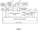
- the system includes a rotary transformer decoder 11, a low pass filter 12 and a microprocessor 13.
- the microprocessor 13 includes a synchronous demodulation module 131 and a calculation module 132.
- the rotary transformer decoder 11 is electrically connected to the rotary transformer through the low pass filter 12, and is configured to output an excitation signal to drive the rotary transformer and acquire first position information of the motor rotor of the rotary transformer.
- the first position information includes at least a first rotor position and a first rotor speed.
- the synchronous demodulation module 131 is electrically connected to the rotary transformer decoder 11 and the rotary transformer, and is configured to collect at least a rotary transformer cosine signal and a rotary transformer sinusoidal signal outputted from the rotary transformer and output a feedback signal.
- the feedback signal includes at least a target rotary transformer sinusoidal signal and a target rotary transformer cosine signal.
- the calculation module 132 is connected to the synchronous demodulation module 131, and is configured to perform calculation to acquire second position information of the motor rotor of the rotary transformer based on the feedback signal and according to a preset algorithm.
- the second position information includes at least a second rotor position and a second rotor speed.
- the rotary transformer decoder acquires the rotor position
- the synchronous demodulation module acquires the rotary transformer sinusoid signal and the rotary transformer cosine signal outputted from the rotary transformer decoder
- the calculation module acquires another rotor position according to a preset algorithm.
- the system for acquiring a rotor position of a rotary transformer may further include a comparison module.
- the comparison module is configured to compare the first position information with the second position information. In a case that a difference between the first position information and the second position information is less than or equal to a first preset threshold, one of the first position information and the second position information is outputted as target output information of the rotary transformer. In a case that the difference between the first position information and the second position information is greater than the first preset threshold, an alarm message is sent.
- the rotary transformer decoder and software decoding are integrated into the motor control system to acquire two rotor positions of the motor rotor, and the two rotor positions are compared.
- one of the rotor positions is used for motor control, and the other is used as redundant data for backup, thereby improving the reliability of the acquired rotor position.
- FIG. 2 is a schematic structural diagram of a synchronous demodulation module in a system for acquiring a rotor position of a rotary transformer according to an embodiment of the present disclosure.
- the synchronous demodulation module includes: a first analog-to-digital conversion module, a first low pass filter, and a first data decimation module.
- the first analog-to-digital conversion module is configured to acquire a first excitation signal with a phase delay of a first preset value obtained based on the excitation signal, the rotary transformer sinusoidal signal and the rotary transformer cosine signal with a phase delay of a second preset value, output a first digitalized excitation signal, a first digitalized rotary transformer sinusoidal signal, and a first digitalized rotary transformer cosine signal. Calculation is performed based on the first digitalized excitation signal, the first digitalized rotating sinusoidal signal, and the first digitalized rotating cosine signal, to acquire a first signal and a second signal.
- the first low pass filter is configured to filter the first signal and the second signal to acquire a first filtered signal and a second filtered signal.
- the first data decimation module is configured perform data decimation on the first filtered signal and the second filtered signal to acquire the target rotary transformer sinusoidal signal and the target rotary transformer cosine signal, respectively.
- an absolute value of the difference between the first preset value and the second preset value is less than or equal to 45 degrees.
- the calculation performed based on the first digitalized excitation signal, the first digitalized rotating sinusoidal signal, and the first digitalized rotating cosine signal, to acquire the first signal and the second signal includes: obtaining a product of the first digitalized excitation signal and the first digitalized rotary transformer sinusoidal signal as the first signal, and obtaining a product of the first digitalized excitation signal and the first digitalized rotary transformer cosine signal as the second signal.
- a first embodiment is described in combination with Figure 2 .
- the rotary transformer decoder sends an excitation signal u 0 (t), which is a sinusoidal signal, to the rotary transformer.
- the excitation signal u 0 (t) is filtered by a low pass filter.
- a phase delay with a first preset value ⁇ is introduced into the excitation signal u 0 (t) by a conditioning circuit of the synchronous demodulation module for collecting the excitation signal, to obtain a first excitation signal.
- the first excitation signal is inputted into the first analog-to-digital conversion module ADC to obtain a first digitalized excitation signal u 0 '(t).
- the first rotary transformer sinusoidal signal and the first rotary transformer cosine signal are filtered by low pass filters and are inputted into the synchronous demodulation module.
- Another phase delay with a second preset value ⁇ is introduced by the conditioning circuit and the rotary transformer to the first rotary transformer sinusoidal signal and the first rotary transformer cosine signal, which is also inputted into the first analog-to-digital conversion module ADC to obtain a first digitalized rotary transformer sinusoidal signal u 1 '(t), and a first digitalized rotary transformer cosine signal u 2 '(t).
- the first signal V S (t) and the second signal V C (t) are obtained based on the first digitalized excitation signal u 0 '(t), the first digitalized rotary transformer sinusoidal signal u 1 '(t), and the first digitalized rotary transformer cosine signal u 2 '(t) according to the following equations:
- the amplitudes of the target rotary transformer sinusoidal signal Vs'(t) and the target rotary transformer cosine signal V C '(t) are maintained close to U 0 2 /2, that is, the difference between the first preset value ⁇ and the second preset value ⁇ , that characterizes the delayed phases, needs to be less than or equal to ⁇ 45 degrees.
- the synchronous demodulation module includes: a pulse capture module, a signal construction module, a second analog-to-digital conversion module, a second low pass filter, and a second data decimation module.
- the excitation signal is converted into a second excitation signal by a preset comparator.
- the pulse capture module is configured to acquire a period of the second excitation signal.
- the signal construction module is connected to the pulse capture module, and is configured to acquire a signal parameter of the excitation signal and construct a constructed excitation signal based on the signal parameter.
- the signal parameter includes at least a frequency and a phase of the excitation signal.
- the second analog-to-digital conversion module is configured to acquire the rotary transformer sinusoidal signal and the rotary transformer cosine signal, and output a second digitalized rotary transformer sinusoidal signal and a second digitalized rotary transformer cosine signal. Calculation is performed based on the constructed excitation signal, the second digitalized rotary transformer sinusoidal signal, and the second digitalized rotary transformer cosine signal, to acquire a third signal and a fourth signal.
- the second low pass filter is configured to filter the third signal and the fourth signal to acquire a third filtered signal and a fourth filtered signal.
- the second data decimation module is configured to perform data decimation on the third filtered signal and the fourth filtered signal to acquire the target rotary transformer sinusoidal signal and the target rotary transformer cosine signal.
- the calculation performed based on the constructed excitation signal, the second digitalized rotary transformer sinusoidal signal, and the second digitalized rotary transformer cosine signal, to acquire the third signal and the fourth signal includes: obtaining a product of the constructed excitation signal and the second digitalized rotary transformer sinusoidal signal as the third signal, and obtaining a product of the constructed excitation signal and the second digitalized rotary transformer cosine signal as the fourth signal.
- the excitation signal is filtered by a low pass filter and is converted into a square wave signal containing the excitation phase and frequency information by a preset comparator.
- the square wave signal is inputted into the pulse capture module (the eCAP of the synchronous demodulation module shown in Figure 3 ) and the signal construction module, by which the frequency and the phase of the excitation signal is acquired, and a constructed excitation signal is constructed based on the frequency and the phase of the excitation signal.
- the preset value ⁇ of the phase delay in the second embodiment is set by software, which is convenient for modification.
- the amplitudes of the target rotatory transformer sinusoidal signal Vs'(t) and the target rotatory transformer cosine signal V C '(t) are maintained close to U 0 2 /2.
- the process in subsequent stages is the same as that in the first embodiment. That is, calculation is performed based on the constructed excitation signal, the second digitalized rotary transformer sinusoidal signal, and the second digitalized rotary transformer cosine signal, to acquire a third signal and a fourth signal. Then, the third signal and the fourth signal are filtered by the second low pass filter to acquire a third filtered signal and a fourth filtered signal.
- the second data decimation module performs data decimation on the third filtered signal and the fourth filtered signal to acquire the target rotary transformer sinusoidal signal Vs'(t) and the target rotary transformer cosine signal Vc'(t).
- phases of the target rotary transformer sinusoidal signal Vs'(t) and the target rotary transformer cosine signal Vc'(t) are locked to acquire the second rotor position and the second rotor speed of the rotary transformer, based on an observer.
- phases of the third signal and the fourth signal are locked to acquire the rotor position and the rotor speed of the rotary transformer, based on an observer.
- the rotary transformer decoder and software decoding are integrated into the motor control system to acquire two rotor positions of the motor rotor, and the two rotor positions are compared.
- one of the rotor positions is used for motor control, and the other is used as redundant data for backup, thereby improving the reliability of the acquired rotor position.
- a method for acquiring a rotor position of a rotary transformer is further provided according to an embodiment of the present disclosure.
- the method is applicable to the system for acquiring a rotor position of a rotary transformer according to any one of the above embodiments.
- the method includes the following steps S41 to S44.
- step S41 an excitation signal is outputted to drive the rotary transformer.
- step S42 first position information of the motor rotor of the rotary transformer is acquired.
- the first position information includes at least a first rotor position and a first rotor speed.
- step S43 at least a rotary transformer cosine signal and a rotary transformer sinusoidal signal outputted from the rotary transformer are acquired, and a feedback signal is outputted.
- the feedback signal includes at least a target rotary transformer sinusoidal signal and a target rotary transformer cosine signal.
- step S44 calculation is performed to acquire second position information of the motor rotor of the rotary transformer, based on the feedback signal and according to a preset algorithm.
- the second position information includes at least a second rotor position and a second rotor speed.
- the method further includes the following step S51.
- step S51 the first position information is compared with the second position information.
- One of the first position information and the second position information is outputted as a target output information of the rotary transformer in a case that a difference between the first position information and the second position information is less than or equal to a first preset threshold.
- An alarm message is sent in a case that the difference between the first position information and the second position information is greater than the first preset threshold.
- the system includes: a rotary transformer decoder, a low pass filter and a microprocessor.
- the microprocessor includes a synchronous demodulation module and a calculation module.
- the rotary transformer decoder is configured to output an excitation signal to drive the rotary transformer and acquire first position information of the motor rotor of the rotary transformer, the first position information including at least a first rotor position and a first rotor speed.
- the synchronous demodulation module is configured to collect at least a rotary transformer cosine signal and a rotary transformer sinusoidal signal outputted from the rotary transformer and output a feedback signal.
- the feedback signal includes at least a target rotary transformer sinusoidal signal and a target rotary transformer cosine signal.
- the calculation module is configured to perform calculation to acquire second position information of the motor rotor of the rotary transformer based on the feedback signal and according to a preset algorithm.
- the second position information includes at least a second rotor position and a second rotor speed.
- the rotary transformer decoder and software decoding are integrated into the motor control system to acquire two rotor positions, and the two rotor positions are compared. In a case that a preset determining condition is met, one of the rotor positions is used for motor control, and the other is used as redundant data for backup, thereby improving the reliability of the acquired rotor position.
- the steps of the methods or algorithms described in conjunction with the embodiments of the present disclosure can be implemented with hardware, software modules executed by a processor, or a combination thereof.
- the software modules may reside in a Random Access Memory (RAM), an internal memory, a Read Only Memory (ROM), an Electrically Programmable ROM, an Electrically-Erasable Programmable ROM, a register, a hard disk, a removable disk drive, CD-ROM, or other types of storage media well known in the technical field.
Landscapes
- Engineering & Computer Science (AREA)
- Power Engineering (AREA)
- Transmission And Conversion Of Sensor Element Output (AREA)
- Control Of Motors That Do Not Use Commutators (AREA)
- Control Of Ac Motors In General (AREA)
Abstract
Description
- The present disclosure relates to the field of technologies for controlling new energy motors, and in particular to a method and a system for acquiring a rotor position of a rotary transformer.
- The output voltage of a rotary transformer varies with the rotor position. Therefore, the output voltage of the rotary transformer is generally used by a motor control system to acquire the rotor position.
- The rotor position is generally acquired in two manners. In one manner, the rotor position is acquired by a rotary transformer decoder, and then a system microprocessor reads the rotor position via a serial or parallel communication link to the decoder device. In another manner, software decoding is applied, that is, the system microprocessor sends a sinusoidal excitation signal to the rotary transformer, receives a sinusoidal feedback signal and a cosine feedback signal from the rotary transformer via an analog sampling port of the system microprocessor, and performs calculation to acquire the rotor position by using a certain algorithm.
- However, there is a risk of failure when the rotor position is acquired in the above two manners, and inaccurate detection results may lead to a critical system fault. Therefore, an issue to be solved by those skilled in the art is to provide a system for acquiring a rotor position of a rotary transformer, with which the reliability of the acquired rotor position can be improved.
- In view of this, a system for acquiring a rotor position of a rotary transformer is provided according to an embodiment of the present disclosure. In the system, a rotary transformer decoder acquires a rotor position, a synchronous demodulation module acquires a rotary transformer sinusoid signal and a rotary transformer cosine signal outputted from the rotary transformer decoder, and a calculation module acquires another rotor position according to a preset algorithm. With this system, the reliability of the acquired rotor position can be improved.
- The following technical solutions are provided according to the present disclosure to achieve the above object.
- A system for acquiring a rotor position of a rotary transformer is provided, which includes: a rotary transformer decoder, a low pass filter and a microprocessor. The microprocessor includes a synchronous demodulation module and a calculation module.
- The rotary transformer decoder is electrically connected to the rotary transformer through the low pass filter, and is configured to output an excitation signal to drive the rotary transformer and acquire first position information of the motor rotor of the rotary transformer, the first position information including at least a first rotor position and a first rotor speed.
- The synchronous demodulation module is electrically connected to the rotary transformer decoder and the rotary transformer, and is configured to collect at least a rotary transformer cosine signal and a rotary transformer sinusoidal signal outputted from the rotary transformer and output a feedback signal. The feedback signal includes at least a target rotary transformer sinusoidal signal and a target rotary transformer cosine signal.
- The calculation module is connected to the synchronous demodulation module, and is configured to perform calculation to acquire second position information of the motor rotor of the rotary transformer based on the feedback signal and according to a preset algorithm. The second position information includes at least a second rotor position and a second rotor speed.
- In an embodiment, the system further includes a comparison module configured to compare the first position information with the second position information. In a case that a difference between the first position information and the second position information is less than or equal to a first preset threshold, one of the first position information and the second position information is outputted as target output information of the rotary transformer. In a case that the difference between the first position information and the second position information is greater than the first preset threshold, an alarm message is sent.
- In an embodiment, the synchronous demodulation module includes a first analog-to-digital conversion module, a first low pass filter, and a first data decimation module.
- The first analog-to-digital conversion module is configured to acquire a first excitation signal with a phase delay of a first preset value obtained based on the excitation signal, the rotary transformer sinusoidal signal and the rotary transformer cosine signal with a phase delay of a second preset value, output a first digitalized excitation signal, a first digitalized rotary transformer sinusoidal signal, and a first digitalized rotary transformer cosine signal. Calculation is performed based on the first digitalized excitation signal, the first digitalized rotating sinusoidal signal, and the first digitalized rotating cosine signal, to acquire a first signal and a second signal.
- The first low pass filter is configured to filter the first signal and the second signal to acquire a first filtered signal and a second filtered signal.
- The first data decimation module is configured perform data decimation on the first filtered signal and the second filtered signal to acquire the target rotary transformer sinusoidal signal and the target rotary transformer cosine signal, respectively.
- In an embodiment, an absolute value of a difference between the first preset value and the second preset value is less than or equal to 45 degrees.
- In an embodiment, the calculation performed based on the first digitalized excitation signal, the first digitalized rotating sinusoidal signal, and the first digitalized rotating cosine signal, to acquire the first signal and the second signal includes: obtaining a product of the first digitalized excitation signal and the first digitalized rotary transformer sinusoidal signal as the first signal, and obtaining a product of the first digitalized excitation signal and the first digitalized rotary transformer cosine signal as the second signal.
- In an embodiment, the synchronous demodulation module includes a pulse capture module, a signal construction module, a second analog-to-digital conversion module, a second low pass filter, and a second data decimation module.
- The excitation signal is converted into a second excitation signal by a preset comparator. The pulse capture module is configured to acquire a period of the second excitation signal. The signal construction module is connected to the pulse capture module, and is configured to acquire a signal parameter of the excitation signal and construct a constructed excitation signal based on the signal parameter, the signal parameter including at least a frequency and a phase of the excitation signal.
- The second analog-to-digital conversion module is configured to acquire the rotary transformer sinusoidal signal and the rotary transformer cosine signal, and output a second digitalized rotary transformer sinusoidal signal and a second digitalized rotary transformer cosine signal. Calculation is performed based on the constructed excitation signal, the second digitalized rotary transformer sinusoidal signal, and the second digitalized rotary transformer cosine signal, to acquire a third signal and a fourth signal.
- The second low pass filter is configured to filter the third signal and the fourth signal to acquire a third filtered signal and a fourth filtered signal.
- The second data decimation module is configured to perform data decimation on the third filtered signal and the fourth filtered signal to acquire the target rotary transformer sinusoidal signal and the target rotary transformer cosine signal.
- In an embodiment, the calculation performed based on the constructed excitation signal, the second digitalized rotary transformer sinusoidal signal, and the second digitalized rotary transformer cosine signal, to acquire the third signal and the fourth signal includes: obtaining a product of the constructed excitation signal and the second digitalized rotary transformer sinusoidal signal as the third signal, and obtaining a product of the constructed excitation signal and the second digitalized rotary transformer cosine signal as the fourth signal.
- In an embodiment, the calculation module being configured to perform calculation to acquire the second position information of the motor rotor of the rotary transformer based on the feedback signal and according to the preset algorithm includes: the calculation module being configured to lock phases of the target rotary transformer sinusoidal signal and the target rotary transformer cosine signal and acquire the second rotor position and the second rotor speed of the rotary transformer, based on an observer.
- In an embodiment, the calculation module being configured to perform calculation to acquire the second position information of the motor rotor of the rotary transformer based on the feedback signal and according to the preset algorithm includes: the calculation module being configured to lock phases of the target rotary transformer sinusoidal signal and the target rotary transformer cosine signal and acquire the second rotor position and the second rotor speed of the rotary transformer, based on an observer.
- A method for acquiring a rotor position of a rotary transformer is provided. The method is applied to the system for acquiring a rotor position of a rotary transformer according to any one of the above embodiment. The method includes:
- outputting an excitation signal to drive the rotary transformer,
- acquiring first position information of the motor rotor of the rotary transformer, the first position information including at least a first rotor position and a first rotor speed,
- obtaining at least a rotary transformer cosine signal and a rotary transformer sinusoidal signal outputted from the rotary transformer and outputting a feedback signal, the feedback signal including at least a target rotary transformer sinusoidal signal and a target rotary transformer cosine signal, and
- performing calculation to acquire second position information of the motor rotor of the rotary transformer, based on the feedback signal and according to a preset algorithm, the second position information including at least a second rotor position and a second rotor speed.
- In an embodiment, the method further includes:
comparing the first position information with the second position information, outputting one of the first position information and the second position information as a target output information of the rotary transformer in a case that a difference between the first position information and the second position information is less than or equal to a first preset threshold, and sending an alarm message in a case that the difference between the first position information and the second position information is greater than the first preset threshold. - On basis of the above technical solution, a system for acquiring a rotor position of a rotary transformer is provided according to the embodiments of the present disclosure, which includes: a rotary transformer decoder, a low pass filter and a microprocessor. The microprocessor includes a synchronous demodulation module and a calculation module. The rotary transformer decoder is electrically connected to the rotary transformer through the low pass filter, and is configured to output an excitation signal to drive the rotary transformer and acquire first position information of the motor rotor of the rotary transformer, the first position information including at least a first rotor position and a first rotor speed. The synchronous demodulation module is electrically connected to the rotary transformer decoder and the rotary transformer, and is configured to collect at least a rotary transformer cosine signal and a rotary transformer sinusoidal signal outputted from the rotary transformer and output a feedback signal. The feedback signal includes at least a target rotary transformer sinusoidal signal and a target rotary transformer cosine signal. The calculation module is connected to the synchronous demodulation module, and is configured to perform calculation to acquire second position information of the motor rotor of the rotary transformer based on the feedback signal and according to a preset algorithm. The second position information includes at least a second rotor position and a second rotor speed. As can be seen, according to the technical solution of the present disclosure, the rotary transformer decoder acquires the rotor position, the synchronous demodulation module acquires the rotary transformer sinusoid signal and the rotary transformer cosine signal outputted from the rotary transformer decoder, and the calculation module acquires another rotor position according to a preset algorithm. With this system, the reliability of the acquired rotor position can be improved.
- The drawings to be used in the description of the embodiments or the conventional technology will be described briefly as follows, so that the technical solutions according to the embodiments of the present disclosure or according to the conventional technology will become clearer. It is apparent that the drawings in the following description only illustrate some embodiments of the present disclosure. For those skilled in the art, other drawings may be obtained according to these drawings without any creative work.
-
Figure 1 is a schematic structural diagram of a system for acquiring a rotor position of a rotary transformer according to an embodiment of the present disclosure; -
Figure 2 is a schematic structural diagram of a synchronous demodulation module in a system for acquiring a rotor position of a rotary transformer according to an embodiment of the present disclosure; -
Figure 3 is schematic structural diagram of a synchronous demodulation module in a system for acquiring a rotor position of a rotary transformer according to another embodiment of the present disclosure; -
Figure 4 is a flow chart of a method for acquiring a rotor position of a rotary transformer according to an embodiment of the present disclosure; and -
Figure 5 is flow chart of a method for acquiring a rotor position of a rotary transformer according to another embodiment of the present disclosure. - As described in the background, a rotary transformer decoder or software decoding is currently used to acquire a rotor position. However, there is a risk of failure when the rotor position is acquired in the above two manners, and inaccurate detection results may lead to a system fault.
- On this basis, a system for acquiring a rotor position of a rotary transformer is provided according to an embodiment of the present disclosure. In the system, a rotary transformer decoder acquires a rotor position, a synchronous demodulation module acquires a rotary transformer sinusoid signal and a rotary transformer cosine signal outputted from the rotary transformer decoder, and a calculation module acquires another rotor position according to a preset algorithm. With this system, the reliability of the acquired rotor position can be improved. In this solution, the rotary transformer decoder and software decoding are integrated into the motor control system to acquire two rotor positions, and the two rotor positions are compared. In a case that a preset determining condition is met, one of the rotor positions is used for motor control, and the other is used as redundant data for backup, thereby improving the reliability of the acquired rotor position.
- It should be noted that, this solution does not simply combine the rotary transformer decoder with the software decoding. Instead, a rotary transformer decoder output an excitation signal to drive the rotary transformer, and a synchronous demodulation module acquires at least a rotary transformer sinusoidal signal and a rotary transformer cosine signal fed back by the rotary transformer. The rotor positions acquired in the two manners are mutually redundant to improve the reliability of the system function.
- Specifically, the inventors found that the exact phase of the excitation signal cannot be obtained with the existing software decoding program, and therefore it cannot be guaranteed that the feedback rotary transformer sinusoidal signal and the feedback rotary transformer cosine signal are sampled at points near the peak value. Therefore, the result obtained by using the existing software decoding program deviates greatly from the actual value, and cannot be used as redundant data.
- Therefore, a system for acquiring a rotor position of a rotary transformer is provided according to an embodiment of the present disclosure, as shown in
Figure 1 . The system includes arotary transformer decoder 11, alow pass filter 12 and amicroprocessor 13. Themicroprocessor 13 includes asynchronous demodulation module 131 and acalculation module 132. - The
rotary transformer decoder 11 is electrically connected to the rotary transformer through thelow pass filter 12, and is configured to output an excitation signal to drive the rotary transformer and acquire first position information of the motor rotor of the rotary transformer. The first position information includes at least a first rotor position and a first rotor speed. - The
synchronous demodulation module 131 is electrically connected to therotary transformer decoder 11 and the rotary transformer, and is configured to collect at least a rotary transformer cosine signal and a rotary transformer sinusoidal signal outputted from the rotary transformer and output a feedback signal. The feedback signal includes at least a target rotary transformer sinusoidal signal and a target rotary transformer cosine signal. - The
calculation module 132 is connected to thesynchronous demodulation module 131, and is configured to perform calculation to acquire second position information of the motor rotor of the rotary transformer based on the feedback signal and according to a preset algorithm. The second position information includes at least a second rotor position and a second rotor speed. - As can be seen, according to the technical solution of the present disclosure, the rotary transformer decoder acquires the rotor position, the synchronous demodulation module acquires the rotary transformer sinusoid signal and the rotary transformer cosine signal outputted from the rotary transformer decoder, and the calculation module acquires another rotor position according to a preset algorithm. With this system, the reliability of the acquired rotor position can be improved.
- On the basis of the above embodiments, the system for acquiring a rotor position of a rotary transformer provided according an embodiment of the present disclosure may further include a comparison module.
- The comparison module is configured to compare the first position information with the second position information. In a case that a difference between the first position information and the second position information is less than or equal to a first preset threshold, one of the first position information and the second position information is outputted as target output information of the rotary transformer. In a case that the difference between the first position information and the second position information is greater than the first preset threshold, an alarm message is sent.
- In this solution, the rotary transformer decoder and software decoding are integrated into the motor control system to acquire two rotor positions of the motor rotor, and the two rotor positions are compared. In a case that a preset determining condition is met, one of the rotor positions is used for motor control, and the other is used as redundant data for backup, thereby improving the reliability of the acquired rotor position.
- Two structures of the synchronous demodulation module are provided according to the embodiments of the present disclosure. Referring to
Figure 2 , which is a schematic structural diagram of a synchronous demodulation module in a system for acquiring a rotor position of a rotary transformer according to an embodiment of the present disclosure. The synchronous demodulation module includes: a first analog-to-digital conversion module, a first low pass filter, and a first data decimation module. - The first analog-to-digital conversion module is configured to acquire a first excitation signal with a phase delay of a first preset value obtained based on the excitation signal, the rotary transformer sinusoidal signal and the rotary transformer cosine signal with a phase delay of a second preset value, output a first digitalized excitation signal, a first digitalized rotary transformer sinusoidal signal, and a first digitalized rotary transformer cosine signal. Calculation is performed based on the first digitalized excitation signal, the first digitalized rotating sinusoidal signal, and the first digitalized rotating cosine signal, to acquire a first signal and a second signal.
- The first low pass filter is configured to filter the first signal and the second signal to acquire a first filtered signal and a second filtered signal.
- The first data decimation module is configured perform data decimation on the first filtered signal and the second filtered signal to acquire the target rotary transformer sinusoidal signal and the target rotary transformer cosine signal, respectively.
- It should be noted that, an absolute value of the difference between the first preset value and the second preset value is less than or equal to 45 degrees.
- The calculation performed based on the first digitalized excitation signal, the first digitalized rotating sinusoidal signal, and the first digitalized rotating cosine signal, to acquire the first signal and the second signal includes: obtaining a product of the first digitalized excitation signal and the first digitalized rotary transformer sinusoidal signal as the first signal, and obtaining a product of the first digitalized excitation signal and the first digitalized rotary transformer cosine signal as the second signal.
- A first embodiment is described in combination with
Figure 2 . The rotary transformer decoder sends an excitation signal u0(t), which is a sinusoidal signal, to the rotary transformer. The excitation signal u0(t) is filtered by a low pass filter. A phase delay with a first preset value γ is introduced into the excitation signal u0(t) by a conditioning circuit of the synchronous demodulation module for collecting the excitation signal, to obtain a first excitation signal. The first excitation signal is inputted into the first analog-to-digital conversion module ADC to obtain a first digitalized excitation signal u0'(t). The first rotary transformer sinusoidal signal and the first rotary transformer cosine signal are filtered by low pass filters and are inputted into the synchronous demodulation module. Another phase delay with a second preset value δ is introduced by the conditioning circuit and the rotary transformer to the first rotary transformer sinusoidal signal and the first rotary transformer cosine signal, which is also inputted into the first analog-to-digital conversion module ADC to obtain a first digitalized rotary transformer sinusoidal signal u1'(t), and a first digitalized rotary transformer cosine signal u2'(t). Given that the turns ratio of the rotary transformer is 1, and θ is the rotor position, the excitation signal u0(t), the first digitalized excitation signal u0'(t), the first digitalized rotary transformer sinusoidal signal u1'(t), and the first digitalized rotary transformer cosine signal u2'(t) are respectively expressed by the following equations:


- The first signal VS(t) and the second signal VC(t) are obtained based on the first digitalized excitation signal u0'(t), the first digitalized rotary transformer sinusoidal signal u1'(t), and the first digitalized rotary transformer cosine signal u2'(t) according to the following equations:


- The first signal VS(t) and the second signal VC(t) are filtered by the first low pass filter FIR LPF. Only components related to the motor rotor are retained to acquire the first filtered signal and the second filtered signal. Then, the first data decimation module (represented by 2K:1 in
Figure 3 ) performs data decimation on the first filtered signal and the second filtered signal to acquire the target rotary transformer sinusoidal signal VS'(t) and the target rotary transformer cosine signal VC'(t), which are respectively expressed by the following equations:

- In order to ensure the accuracy of the subsequent angle calculation and the phase-locked loop, the amplitudes of the target rotary transformer sinusoidal signal Vs'(t) and the target rotary transformer cosine signal VC'(t) are maintained close to U0 2/2, that is, the difference between the first preset value γ and the second preset value δ, that characterizes the delayed phases, needs to be less than or equal to ±45 degrees.
- A second embodiment is described in combination with
Figure 3 . An implementation of the synchronous demodulation module is provided in this embodiment. The synchronous demodulation module includes: a pulse capture module, a signal construction module, a second analog-to-digital conversion module, a second low pass filter, and a second data decimation module. - The excitation signal is converted into a second excitation signal by a preset comparator. The pulse capture module is configured to acquire a period of the second excitation signal. The signal construction module is connected to the pulse capture module, and is configured to acquire a signal parameter of the excitation signal and construct a constructed excitation signal based on the signal parameter. The signal parameter includes at least a frequency and a phase of the excitation signal.
- The second analog-to-digital conversion module is configured to acquire the rotary transformer sinusoidal signal and the rotary transformer cosine signal, and output a second digitalized rotary transformer sinusoidal signal and a second digitalized rotary transformer cosine signal. Calculation is performed based on the constructed excitation signal, the second digitalized rotary transformer sinusoidal signal, and the second digitalized rotary transformer cosine signal, to acquire a third signal and a fourth signal.
- The second low pass filter is configured to filter the third signal and the fourth signal to acquire a third filtered signal and a fourth filtered signal.
- The second data decimation module is configured to perform data decimation on the third filtered signal and the fourth filtered signal to acquire the target rotary transformer sinusoidal signal and the target rotary transformer cosine signal.
- Specifically, the calculation performed based on the constructed excitation signal, the second digitalized rotary transformer sinusoidal signal, and the second digitalized rotary transformer cosine signal, to acquire the third signal and the fourth signal includes: obtaining a product of the constructed excitation signal and the second digitalized rotary transformer sinusoidal signal as the third signal, and obtaining a product of the constructed excitation signal and the second digitalized rotary transformer cosine signal as the fourth signal.
- As shown in
Figure 3 , the excitation signal is filtered by a low pass filter and is converted into a square wave signal containing the excitation phase and frequency information by a preset comparator. The square wave signal is inputted into the pulse capture module (the eCAP of the synchronous demodulation module shown inFigure 3 ) and the signal construction module, by which the frequency and the phase of the excitation signal is acquired, and a constructed excitation signal is constructed based on the frequency and the phase of the excitation signal. The constructed excitation signal is expressed by the following equation:
- Unlike the first embodiment in which the delay phase is adjusted by adjusting the parameters of the hardware circuit, the preset value γ of the phase delay in the second embodiment is set by software, which is convenient for modification. Similarly, the amplitudes of the target rotatory transformer sinusoidal signal Vs'(t) and the target rotatory transformer cosine signal VC'(t) are maintained close to U0 2/2.
- After the frequency and the phase of the excitation signal are acquired, the process in subsequent stages is the same as that in the first embodiment. That is, calculation is performed based on the constructed excitation signal, the second digitalized rotary transformer sinusoidal signal, and the second digitalized rotary transformer cosine signal, to acquire a third signal and a fourth signal. Then, the third signal and the fourth signal are filtered by the second low pass filter to acquire a third filtered signal and a fourth filtered signal. The second data decimation module performs data decimation on the third filtered signal and the fourth filtered signal to acquire the target rotary transformer sinusoidal signal Vs'(t) and the target rotary transformer cosine signal Vc'(t).
- In addition, after the target rotary transformer sinusoidal signal and the target rotary transformer cosine signal are acquired, phases of the target rotary transformer sinusoidal signal Vs'(t) and the target rotary transformer cosine signal Vc'(t) are locked to acquire the second rotor position and the second rotor speed of the rotary transformer, based on an observer. Alternatively, phases of the third signal and the fourth signal are locked to acquire the rotor position and the rotor speed of the rotary transformer, based on an observer.
- As can be seen, in this solution, the rotary transformer decoder and software decoding are integrated into the motor control system to acquire two rotor positions of the motor rotor, and the two rotor positions are compared. In a case that a preset determining condition is met, one of the rotor positions is used for motor control, and the other is used as redundant data for backup, thereby improving the reliability of the acquired rotor position.
- On basis of the above embodiment, as shown in
Figure 4 , a method for acquiring a rotor position of a rotary transformer is further provided according to an embodiment of the present disclosure. The method is applicable to the system for acquiring a rotor position of a rotary transformer according to any one of the above embodiments. The method includes the following steps S41 to S44. - In step S41, an excitation signal is outputted to drive the rotary transformer.
- In step S42, first position information of the motor rotor of the rotary transformer is acquired. The first position information includes at least a first rotor position and a first rotor speed.
- In step S43, at least a rotary transformer cosine signal and a rotary transformer sinusoidal signal outputted from the rotary transformer are acquired, and a feedback signal is outputted. The feedback signal includes at least a target rotary transformer sinusoidal signal and a target rotary transformer cosine signal.
- In step S44, calculation is performed to acquire second position information of the motor rotor of the rotary transformer, based on the feedback signal and according to a preset algorithm. The second position information includes at least a second rotor position and a second rotor speed.
- In an embodiment, as shown in
Figure 5 , the method further includes the following step S51. - In step S51, the first position information is compared with the second position information. One of the first position information and the second position information is outputted as a target output information of the rotary transformer in a case that a difference between the first position information and the second position information is less than or equal to a first preset threshold. An alarm message is sent in a case that the difference between the first position information and the second position information is greater than the first preset threshold.
- The operating principle of the method embodiment can be referred to the system embodiment above.
- In view of the above, a method and a system for acquiring a rotor position of a rotary transformer is provided according to the embodiments of the present disclosure. The system includes: a rotary transformer decoder, a low pass filter and a microprocessor. The microprocessor includes a synchronous demodulation module and a calculation module. The rotary transformer decoder is configured to output an excitation signal to drive the rotary transformer and acquire first position information of the motor rotor of the rotary transformer, the first position information including at least a first rotor position and a first rotor speed. The synchronous demodulation module is configured to collect at least a rotary transformer cosine signal and a rotary transformer sinusoidal signal outputted from the rotary transformer and output a feedback signal. The feedback signal includes at least a target rotary transformer sinusoidal signal and a target rotary transformer cosine signal. The calculation module is configured to perform calculation to acquire second position information of the motor rotor of the rotary transformer based on the feedback signal and according to a preset algorithm. The second position information includes at least a second rotor position and a second rotor speed. In this solution, the rotary transformer decoder and software decoding are integrated into the motor control system to acquire two rotor positions, and the two rotor positions are compared. In a case that a preset determining condition is met, one of the rotor positions is used for motor control, and the other is used as redundant data for backup, thereby improving the reliability of the acquired rotor position.
- The above embodiments are described in a progressive manner. Embodiments in this specification are described in a progressive manner, each of the embodiments emphasizes differences between the embodiment and other embodiments, and the same or similar parts among the embodiments can be referred to each other. Since device embodiments are similar to method embodiments, the description thereof is relatively simple, and reference may be made to the description of the method embodiments for relevant parts.
- It may be known by those skilled in the art that, units and steps in each method described in conjunction with the embodiments disclosed herein can be realized by electronic hardware, computer software or a combination thereof. In order to clearly illustrate interchangeability of the hardware and the software, steps and composition of each embodiment have been described generally in view of functions in the above specification. Whether the function is executed in a hardware way or in a software way depends on application of the technical solution and design constraint condition. Those skilled in the art can use different method for each application to realize the described function, and this is not considered to be beyond the scope of the application.
- The steps of the methods or algorithms described in conjunction with the embodiments of the present disclosure can be implemented with hardware, software modules executed by a processor, or a combination thereof. The software modules may reside in a Random Access Memory (RAM), an internal memory, a Read Only Memory (ROM), an Electrically Programmable ROM, an Electrically-Erasable Programmable ROM, a register, a hard disk, a removable disk drive, CD-ROM, or other types of storage media well known in the technical field.
- With the above descriptions of the disclosed embodiments, the skilled in the art may practice or use the present disclosure. Various modifications to the embodiments are apparent for the skilled in the art. The general principle suggested herein can be implemented in other embodiments without departing from the spirit or scope of the disclosure. Therefore, the present disclosure should not be limited to the embodiments disclosed herein, but has the widest scope that is conformity with the principle and the novel features disclosed herein.
Claims (10)
- A system for acquiring a rotor position of a rotary transformer, comprising: a rotary transformer decoder, a low pass filter and a microprocessor, wherein
the microprocessor comprises a synchronous demodulation module and a calculation module,
the rotary transformer decoder is electrically connected to the rotary transformer through the low pass filter, and is configured to output an excitation signal to drive the rotary transformer and acquire first position information of the motor rotor, the first position information comprising at least a first rotor position and a first rotor speed,
the synchronous demodulation module is electrically connected to the rotary transformer decoder and the rotary transformer, and is configured to collect at least a rotary transformer cosine signal and a rotary transformer sinusoidal signal outputted from the rotary transformer and output a feedback signal, the feedback signal comprising at least a target rotary transformer sinusoidal signal and a target rotary transformer cosine signal,
the calculation module is connected to the synchronous demodulation module, and is configured to perform calculation to acquire second position information of the motor rotor based on the feedback signal and according to a preset algorithm, the second position information comprising at least a second rotor position and a second rotor speed. - The system according to claim 1, further comprising:a comparison module, configured to compare the first position information with the second position information, whereinin a case that a difference between the first position information and the second position information is less than or equal to a first preset threshold, one of the first position information and the second position information is outputted as target output information of the rotary transformer, andin a case that the difference between the first position information and the second position information is greater than the first preset threshold, an alarm message is sent.
- The system according to claim 1, wherein the synchronous demodulation module comprises: a first analog-to-digital conversion module, a first low pass filter, and a first data decimation module,
the first analog-to-digital conversion module is configured to acquire a first excitation signal with a phase delay of a first preset value obtained based on the excitation signal, the rotary transformer sinusoidal signal and the rotary transformer cosine signal with a phase delay of a second preset value, output a first digitalized excitation signal, a first digitalized rotary transformer sinusoidal signal, and a first digitalized rotary transformer cosine signal, wherein calculation is performed based on the first digitalized excitation signal, the first digitalized rotating sinusoidal signal, and the first digitalized rotating cosine signal, to acquire a first signal and a second signal,
the first low pass filter is configured to filter the first signal and the second signal to acquire a first filtered signal and a second filtered signal, and
the first data decimation module is configured perform data decimation on the first filtered signal and the second filtered signal to acquire the target rotary transformer sinusoidal signal and the target rotary transformer cosine signal, respectively. - The system according to claim 3, wherein,
an absolute value of a difference between the first preset value and the second preset value is less than or equal to 45 degrees. - The system according to claim 3, wherein the calculation performed based on the first digitalized excitation signal, the first digitalized rotating sinusoidal signal, and the first digitalized rotating cosine signal, to acquire the first signal and the second signal comprises:obtaining a product of the first digitalized excitation signal and the first digitalized rotary transformer sinusoidal signal as the first signal, andobtaining a product of the first digitalized excitation signal and the first digitalized rotary transformer cosine signal as the second signal.
- The system according to claim 1, wherein the synchronous demodulation module comprises: a pulse capture module, a signal construction module, a second analog-to-digital conversion module, a second low pass filter, and a second data decimation module,
the excitation signal is converted into a second excitation signal by a preset comparator, the pulse capture module is configured to acquire a period of the second excitation signal,
the signal construction module is connected to the pulse capture module, and is configured to acquire a signal parameter of the excitation signal and construct a constructed excitation signal based on the signal parameter, the signal parameter comprising at least a frequency and a phase of the excitation signal,
the second analog-to-digital conversion module is configured to acquire the rotary transformer sinusoidal signal and the rotary transformer cosine signal, and output a second digitalized rotary transformer sinusoidal signal and a second digitalized rotary transformer cosine signal, wherein calculation is performed based on the constructed excitation signal, the second digitalized rotary transformer sinusoidal signal, and the second digitalized rotary transformer cosine signal, to acquire a third signal and a fourth signal,
the second low pass filter is configured to filter the third signal and the fourth signal to acquire a third filtered signal and a fourth filtered signal, and
the second data decimation module is configured to perform data decimation on the third filtered signal and the fourth filtered signal to acquire the target rotary transformer sinusoidal signal and the target rotary transformer cosine signal. - The system according to claim 6, wherein the calculation performed based on the constructed excitation signal, the second digitalized rotary transformer sinusoidal signal, and the second digitalized rotary transformer cosine signal, to acquire the third signal and the fourth signal comprises:obtaining a product of the constructed excitation signal and the second digitalized rotary transformer sinusoidal signal as the third signal, andobtaining a product of the constructed excitation signal and the second digitalized rotary transformer cosine signal as the fourth signal.
- The system according to claim 5 or 7, wherein the calculation module being configured to perform calculation to acquire the second position information of the motor rotor based on the feedback signal and according to the preset algorithm comprises:
the calculation module being configured to
lock phases of the target rotary transformer sinusoidal signal and the target rotary transformer cosine signal and acquire the second rotor position and the second rotor speed of the rotary transformer, based on an observer. - A method for acquiring a rotor position of a rotary transformer, applied to the system for acquiring a rotor position of a rotary transformer according to any one of claims 1 to 8, comprising:outputting an excitation signal to drive the rotary transformer,acquiring first position information of the motor rotor, the first position information comprising at least a first rotor position and a first rotor speed,acquiring at least a rotary transformer cosine signal and a rotary transformer sinusoidal signal outputted from the rotary transformer and outputting a feedback signal, the feedback signal comprising at least a target rotary transformer sinusoidal signal and a target rotary transformer cosine signal, andperforming calculation to acquire second position information of the motor rotor, based on the feedback signal and according to a preset algorithm, the second position information comprising at least a second rotor position and a second rotor speed.
- The method according to claim 9, further comprising:comparing the first position information with the second position information,outputting one of the first position information and the second position information as a target output information of the rotary transformer, in a case that a difference between the first position information and the second position information is less than or equal to a first preset threshold, andsending an alarm message, in a case that the difference between the first position information and the second position information is greater than the first preset threshold.
Applications Claiming Priority (1)
| Application Number | Priority Date | Filing Date | Title |
|---|---|---|---|
| CN201810538186.4A CN108599664B (en) | 2018-05-30 | 2018-05-30 | Method and system for acquiring position of motor rotor of rotary transformer |
Publications (2)
| Publication Number | Publication Date |
|---|---|
| EP3575748A1 true EP3575748A1 (en) | 2019-12-04 |
| EP3575748B1 EP3575748B1 (en) | 2021-12-08 |
Family
ID=63629751
Family Applications (1)
| Application Number | Title | Priority Date | Filing Date |
|---|---|---|---|
| EP19157711.3A Active EP3575748B1 (en) | 2018-05-30 | 2019-02-18 | Method and system for acquiring rotor position of rotary transformer |
Country Status (3)
| Country | Link |
|---|---|
| US (1) | US10644626B2 (en) |
| EP (1) | EP3575748B1 (en) |
| CN (1) | CN108599664B (en) |
Cited By (2)
| Publication number | Priority date | Publication date | Assignee | Title |
|---|---|---|---|---|
| CN117792192A (en) * | 2024-02-23 | 2024-03-29 | 潍柴动力股份有限公司 | A rotary soft decoding method, device, equipment and medium |
| CN121364423A (en) * | 2025-12-22 | 2026-01-20 | 苏州弘远电气股份有限公司 | Adaptive decoding method and device for rotary transformer |
Families Citing this family (21)
| Publication number | Priority date | Publication date | Assignee | Title |
|---|---|---|---|---|
| CN109495051A (en) * | 2018-11-20 | 2019-03-19 | 陕西航空电气有限责任公司 | A kind of aviation starting motor position detection redundancy control method |
| DE102018130972A1 (en) * | 2018-12-05 | 2020-06-10 | HELLA GmbH & Co. KGaA | Device, arrangement and method for determining an angle between a rotor and a stator |
| CN111071256A (en) * | 2019-10-31 | 2020-04-28 | 的卢技术有限公司 | Vehicle travel calculation method and system based on motor rotation angle |
| CN110726934B (en) * | 2019-11-07 | 2021-12-28 | 陕西航空电气有限责任公司 | Method for detecting fault of rotary circuit of aviation starting motor by adopting AD2S1210 rotary transformer decoding chip |
| CN111245443B (en) * | 2020-03-06 | 2023-04-25 | 创驱(上海)新能源科技有限公司 | A kind of resolver soft decoding processing method and device based on DSADC |
| WO2021237591A1 (en) * | 2020-05-28 | 2021-12-02 | 华为数字能源技术有限公司 | Motor angle detection and diagnosis device, motor controller, electric vehicle and method |
| CN111726047B (en) * | 2020-06-29 | 2022-05-06 | 德尔福科技(苏州)有限公司 | A Resolver Software Decoding Method Suitable for Motor Control |
| CN112511174B (en) * | 2020-09-25 | 2022-10-14 | 上海擎度汽车科技有限公司 | Rotary soft decoding method meeting functional safety requirements |
| CN112491306A (en) * | 2020-11-27 | 2021-03-12 | 苏州绿控传动科技股份有限公司 | Method and system for verifying rotation soft decoding precision |
| CN112542966A (en) * | 2020-11-27 | 2021-03-23 | 苏州绿控传动科技股份有限公司 | Rotary transformer decoding system |
| CN113985860B (en) * | 2021-12-27 | 2022-05-17 | 苏州英特模汽车科技有限公司 | A resolver simulation equipment and test system with multiple working modes |
| CN114465544B (en) * | 2022-03-30 | 2023-08-08 | 深蓝汽车科技有限公司 | Rotary-variable decoding device and automobile |
| CN114865981B (en) * | 2022-06-13 | 2026-01-13 | 中国第一汽车股份有限公司 | Motor rotation speed estimation system and method |
| CN115411978B (en) * | 2022-08-12 | 2025-05-13 | 浙江吉利控股集团有限公司 | Motor position signal fault judgment method, device, system and vehicle |
| CN115296566A (en) * | 2022-09-05 | 2022-11-04 | 珠海格力电器股份有限公司 | Rotary transformer decoding method, device and system |
| CN115514282B (en) * | 2022-09-20 | 2025-07-08 | 哈尔滨工业大学 | High-precision rotor position acquisition method of rotary transformer full-digital shaft angle conversion system |
| CN115563467A (en) * | 2022-09-23 | 2023-01-03 | 杭州电子科技大学 | A Position Calculation Method of Resolver |
| CN115913039A (en) * | 2022-11-07 | 2023-04-04 | 苏州汇川联合动力系统有限公司 | Resolver signal decoding method, device, equipment and medium |
| CN116101063B (en) * | 2023-02-20 | 2025-09-09 | 丽水方德智驱应用技术研究院有限公司 | Control method for preventing power loss of electric drive system |
| CN117040321B (en) * | 2023-08-11 | 2025-10-03 | 通用技术集团机床工程研究院有限公司上海分公司 | Drive control system and speed control method |
| CN119845311A (en) * | 2024-12-24 | 2025-04-18 | 紫光同芯微电子有限公司 | Signal loop adjusting method and device, electronic equipment and storage medium |
Citations (3)
| Publication number | Priority date | Publication date | Assignee | Title |
|---|---|---|---|---|
| CN102937787A (en) * | 2011-09-06 | 2013-02-20 | 北京理工大学 | Double-rotary-transformer signal processing system |
| CN106092150A (en) * | 2016-06-01 | 2016-11-09 | 同济大学 | The location information acquisition method of rotary transformer, system and electronic equipment |
| US20170227567A1 (en) * | 2016-02-04 | 2017-08-10 | GM Global Technology Operations LLC | Method and apparatus to monitor a resolver |
Family Cites Families (10)
| Publication number | Priority date | Publication date | Assignee | Title |
|---|---|---|---|---|
| JP3136937B2 (en) * | 1995-02-06 | 2001-02-19 | トヨタ自動車株式会社 | Method and apparatus for detecting disconnection of resolver |
| JP2000206127A (en) * | 1999-01-19 | 2000-07-28 | Tamagawa Seiki Co Ltd | Speed detection method |
| CN102721362B (en) * | 2012-06-27 | 2015-05-20 | 同济大学 | Rotating transformer position measuring system and method |
| SG196731A1 (en) * | 2012-07-16 | 2014-02-13 | Agency Science Tech & Res | Method and system for controlling a motor |
| US9413276B2 (en) * | 2014-09-24 | 2016-08-09 | Process Control Corporation | DC motor control over wide dynamic range |
| CN204269070U (en) * | 2014-12-01 | 2015-04-15 | 杭州湘滨电子科技有限公司 | A kind of change of revolving of measuring permanent-magnet synchronous motor rotor position angle encourages and decoder module |
| CN105763128B (en) * | 2016-04-01 | 2018-09-11 | 北京新能源汽车股份有限公司 | Fault information processing method and system for rotary transformer decoding chip |
| CN105915127A (en) * | 2016-06-01 | 2016-08-31 | 同济大学 | Motor rotor position redundant measuring method and system and electronic device |
| CN106953557A (en) * | 2017-03-17 | 2017-07-14 | 深圳市大地和电气股份有限公司 | Rotary transformer converter, signals of rotating transformer acquisition system and acquisition method |
| CN107863913B (en) * | 2017-11-24 | 2019-07-16 | 成都雅骏新能源汽车科技股份有限公司 | A kind of coding/decoding method and system of rotary transformer |
-
2018
- 2018-05-30 CN CN201810538186.4A patent/CN108599664B/en active Active
-
2019
- 2019-02-18 EP EP19157711.3A patent/EP3575748B1/en active Active
- 2019-02-22 US US16/283,402 patent/US10644626B2/en active Active
Patent Citations (3)
| Publication number | Priority date | Publication date | Assignee | Title |
|---|---|---|---|---|
| CN102937787A (en) * | 2011-09-06 | 2013-02-20 | 北京理工大学 | Double-rotary-transformer signal processing system |
| US20170227567A1 (en) * | 2016-02-04 | 2017-08-10 | GM Global Technology Operations LLC | Method and apparatus to monitor a resolver |
| CN106092150A (en) * | 2016-06-01 | 2016-11-09 | 同济大学 | The location information acquisition method of rotary transformer, system and electronic equipment |
Cited By (2)
| Publication number | Priority date | Publication date | Assignee | Title |
|---|---|---|---|---|
| CN117792192A (en) * | 2024-02-23 | 2024-03-29 | 潍柴动力股份有限公司 | A rotary soft decoding method, device, equipment and medium |
| CN121364423A (en) * | 2025-12-22 | 2026-01-20 | 苏州弘远电气股份有限公司 | Adaptive decoding method and device for rotary transformer |
Also Published As
| Publication number | Publication date |
|---|---|
| CN108599664A (en) | 2018-09-28 |
| EP3575748B1 (en) | 2021-12-08 |
| US20190372491A1 (en) | 2019-12-05 |
| CN108599664B (en) | 2021-01-08 |
| US10644626B2 (en) | 2020-05-05 |
Similar Documents
| Publication | Publication Date | Title |
|---|---|---|
| US10644626B2 (en) | Method and system for acquiring rotor position of rotary transformer | |
| US9806656B1 (en) | Fault tolerant phase current measurement for motor control systems | |
| EP2270974B1 (en) | Method for determining rotor position of an electrical generator in a wind turbine | |
| CN113866480A (en) | Detection of offset errors in phase current measurements for motor control systems | |
| CN110596583A (en) | Variable frequency motor stator fault detection system based on zero sequence voltage analysis and detection method thereof | |
| JP7161439B2 (en) | Semiconductor device and motor control system | |
| CN101964655B (en) | Balance error elimination type high-precision digital phase locking method | |
| CN104852662A (en) | Method and system for measuring static inductance parameters of permanent magnet synchronous motor | |
| CN108631656B (en) | A kind of rotary transformer coding/decoding method and system | |
| JP5773932B2 (en) | Electric motor rotation information detection method, electric motor rotation information detection device, electric motor control device | |
| CN111896869A (en) | Five-phase permanent magnet synchronous motor open-circuit fault diagnosis method | |
| CN103546149A (en) | Phase locking method for three-phase power system | |
| CN104579085B (en) | The detection method and detection means of motor rotor position | |
| CN115528739B (en) | Parallel operation synchronization method and system for single-phase inverter, single-phase inverter and storage medium | |
| CN111162717A (en) | Method and device for detecting initial position angle of permanent magnet synchronous motor rotor and storage medium | |
| CN115733408A (en) | A method and device for calculating the rotational speed of an aviation permanent magnet motor without a position sensor | |
| US9608650B1 (en) | Method and device for controlling single-phase phase-locked loop | |
| US11169211B2 (en) | Systems, methods and apparatuses for frequency tracking | |
| CN112583402A (en) | Phase locking method, phase-locked loop, three-phase grid-connected system and computer storage medium | |
| CN117614020A (en) | A software phase-locked loop method, device and medium | |
| CN116683821A (en) | Method and device for inhibiting rotational speed surge of driving wheel of electric vehicle during emptying | |
| CN111566938B (en) | Single-phase adaptive phase locking device and method | |
| CN112003609A (en) | Construction method of self-adaptive frequency-locked loop based on quadrature phasor | |
| CN119001215A (en) | Blade state detection method and device, unmanned equipment and storage medium | |
| CN115508605B (en) | A method for extracting signal characteristics in dynamic process of power system |
Legal Events
| Date | Code | Title | Description |
|---|---|---|---|
| PUAI | Public reference made under article 153(3) epc to a published international application that has entered the european phase |
Free format text: ORIGINAL CODE: 0009012 |
|
| STAA | Information on the status of an ep patent application or granted ep patent |
Free format text: STATUS: THE APPLICATION HAS BEEN PUBLISHED |
|
| AK | Designated contracting states |
Kind code of ref document: A1 Designated state(s): AL AT BE BG CH CY CZ DE DK EE ES FI FR GB GR HR HU IE IS IT LI LT LU LV MC MK MT NL NO PL PT RO RS SE SI SK SM TR |
|
| AX | Request for extension of the european patent |
Extension state: BA ME |
|
| STAA | Information on the status of an ep patent application or granted ep patent |
Free format text: STATUS: REQUEST FOR EXAMINATION WAS MADE |
|
| 17P | Request for examination filed |
Effective date: 20200604 |
|
| RBV | Designated contracting states (corrected) |
Designated state(s): AL AT BE BG CH CY CZ DE DK EE ES FI FR GB GR HR HU IE IS IT LI LT LU LV MC MK MT NL NO PL PT RO RS SE SI SK SM TR |
|
| REG | Reference to a national code |
Ref country code: DE Ref legal event code: R079 Ref document number: 602019009801 Country of ref document: DE Free format text: PREVIOUS MAIN CLASS: G01D0005120000 Ipc: H02P0006160000 |
|
| GRAP | Despatch of communication of intention to grant a patent |
Free format text: ORIGINAL CODE: EPIDOSNIGR1 |
|
| STAA | Information on the status of an ep patent application or granted ep patent |
Free format text: STATUS: GRANT OF PATENT IS INTENDED |
|
| RIC1 | Information provided on ipc code assigned before grant |
Ipc: H02P 6/16 20160101AFI20210618BHEP Ipc: H02P 23/14 20060101ALI20210618BHEP Ipc: G01D 5/12 20060101ALI20210618BHEP Ipc: G01D 5/20 20060101ALN20210618BHEP |
|
| INTG | Intention to grant announced |
Effective date: 20210709 |
|
| RIC1 | Information provided on ipc code assigned before grant |
Ipc: H02P 6/16 20160101AFI20210627BHEP Ipc: H02P 23/14 20060101ALI20210627BHEP Ipc: G01D 5/12 20060101ALI20210627BHEP Ipc: G01D 5/20 20060101ALN20210627BHEP |
|
| GRAS | Grant fee paid |
Free format text: ORIGINAL CODE: EPIDOSNIGR3 |
|
| GRAA | (expected) grant |
Free format text: ORIGINAL CODE: 0009210 |
|
| STAA | Information on the status of an ep patent application or granted ep patent |
Free format text: STATUS: THE PATENT HAS BEEN GRANTED |
|
| AK | Designated contracting states |
Kind code of ref document: B1 Designated state(s): AL AT BE BG CH CY CZ DE DK EE ES FI FR GB GR HR HU IE IS IT LI LT LU LV MC MK MT NL NO PL PT RO RS SE SI SK SM TR |
|
| REG | Reference to a national code |
Ref country code: GB Ref legal event code: FG4D |
|
| REG | Reference to a national code |
Ref country code: AT Ref legal event code: REF Ref document number: 1454504 Country of ref document: AT Kind code of ref document: T Effective date: 20211215 Ref country code: CH Ref legal event code: EP |
|
| REG | Reference to a national code |
Ref country code: DE Ref legal event code: R096 Ref document number: 602019009801 Country of ref document: DE |
|
| REG | Reference to a national code |
Ref country code: IE Ref legal event code: FG4D |
|
| REG | Reference to a national code |
Ref country code: LT Ref legal event code: MG9D |
|
| REG | Reference to a national code |
Ref country code: NL Ref legal event code: MP Effective date: 20211208 |
|
| PG25 | Lapsed in a contracting state [announced via postgrant information from national office to epo] |
Ref country code: RS Free format text: LAPSE BECAUSE OF FAILURE TO SUBMIT A TRANSLATION OF THE DESCRIPTION OR TO PAY THE FEE WITHIN THE PRESCRIBED TIME-LIMIT Effective date: 20211208 Ref country code: LT Free format text: LAPSE BECAUSE OF FAILURE TO SUBMIT A TRANSLATION OF THE DESCRIPTION OR TO PAY THE FEE WITHIN THE PRESCRIBED TIME-LIMIT Effective date: 20211208 Ref country code: FI Free format text: LAPSE BECAUSE OF FAILURE TO SUBMIT A TRANSLATION OF THE DESCRIPTION OR TO PAY THE FEE WITHIN THE PRESCRIBED TIME-LIMIT Effective date: 20211208 Ref country code: BG Free format text: LAPSE BECAUSE OF FAILURE TO SUBMIT A TRANSLATION OF THE DESCRIPTION OR TO PAY THE FEE WITHIN THE PRESCRIBED TIME-LIMIT Effective date: 20220308 |
|
| REG | Reference to a national code |
Ref country code: AT Ref legal event code: MK05 Ref document number: 1454504 Country of ref document: AT Kind code of ref document: T Effective date: 20211208 |
|
| PG25 | Lapsed in a contracting state [announced via postgrant information from national office to epo] |
Ref country code: SE Free format text: LAPSE BECAUSE OF FAILURE TO SUBMIT A TRANSLATION OF THE DESCRIPTION OR TO PAY THE FEE WITHIN THE PRESCRIBED TIME-LIMIT Effective date: 20211208 Ref country code: NO Free format text: LAPSE BECAUSE OF FAILURE TO SUBMIT A TRANSLATION OF THE DESCRIPTION OR TO PAY THE FEE WITHIN THE PRESCRIBED TIME-LIMIT Effective date: 20220308 Ref country code: LV Free format text: LAPSE BECAUSE OF FAILURE TO SUBMIT A TRANSLATION OF THE DESCRIPTION OR TO PAY THE FEE WITHIN THE PRESCRIBED TIME-LIMIT Effective date: 20211208 Ref country code: HR Free format text: LAPSE BECAUSE OF FAILURE TO SUBMIT A TRANSLATION OF THE DESCRIPTION OR TO PAY THE FEE WITHIN THE PRESCRIBED TIME-LIMIT Effective date: 20211208 Ref country code: GR Free format text: LAPSE BECAUSE OF FAILURE TO SUBMIT A TRANSLATION OF THE DESCRIPTION OR TO PAY THE FEE WITHIN THE PRESCRIBED TIME-LIMIT Effective date: 20220309 Ref country code: ES Free format text: LAPSE BECAUSE OF FAILURE TO SUBMIT A TRANSLATION OF THE DESCRIPTION OR TO PAY THE FEE WITHIN THE PRESCRIBED TIME-LIMIT Effective date: 20211208 |
|
| PG25 | Lapsed in a contracting state [announced via postgrant information from national office to epo] |
Ref country code: NL Free format text: LAPSE BECAUSE OF FAILURE TO SUBMIT A TRANSLATION OF THE DESCRIPTION OR TO PAY THE FEE WITHIN THE PRESCRIBED TIME-LIMIT Effective date: 20211208 |
|
| PG25 | Lapsed in a contracting state [announced via postgrant information from national office to epo] |
Ref country code: SM Free format text: LAPSE BECAUSE OF FAILURE TO SUBMIT A TRANSLATION OF THE DESCRIPTION OR TO PAY THE FEE WITHIN THE PRESCRIBED TIME-LIMIT Effective date: 20211208 Ref country code: SK Free format text: LAPSE BECAUSE OF FAILURE TO SUBMIT A TRANSLATION OF THE DESCRIPTION OR TO PAY THE FEE WITHIN THE PRESCRIBED TIME-LIMIT Effective date: 20211208 Ref country code: RO Free format text: LAPSE BECAUSE OF FAILURE TO SUBMIT A TRANSLATION OF THE DESCRIPTION OR TO PAY THE FEE WITHIN THE PRESCRIBED TIME-LIMIT Effective date: 20211208 Ref country code: PT Free format text: LAPSE BECAUSE OF FAILURE TO SUBMIT A TRANSLATION OF THE DESCRIPTION OR TO PAY THE FEE WITHIN THE PRESCRIBED TIME-LIMIT Effective date: 20220408 Ref country code: EE Free format text: LAPSE BECAUSE OF FAILURE TO SUBMIT A TRANSLATION OF THE DESCRIPTION OR TO PAY THE FEE WITHIN THE PRESCRIBED TIME-LIMIT Effective date: 20211208 Ref country code: CZ Free format text: LAPSE BECAUSE OF FAILURE TO SUBMIT A TRANSLATION OF THE DESCRIPTION OR TO PAY THE FEE WITHIN THE PRESCRIBED TIME-LIMIT Effective date: 20211208 |
|
| PG25 | Lapsed in a contracting state [announced via postgrant information from national office to epo] |
Ref country code: PL Free format text: LAPSE BECAUSE OF FAILURE TO SUBMIT A TRANSLATION OF THE DESCRIPTION OR TO PAY THE FEE WITHIN THE PRESCRIBED TIME-LIMIT Effective date: 20211208 Ref country code: AT Free format text: LAPSE BECAUSE OF FAILURE TO SUBMIT A TRANSLATION OF THE DESCRIPTION OR TO PAY THE FEE WITHIN THE PRESCRIBED TIME-LIMIT Effective date: 20211208 |
|
| REG | Reference to a national code |
Ref country code: DE Ref legal event code: R097 Ref document number: 602019009801 Country of ref document: DE |
|
| PG25 | Lapsed in a contracting state [announced via postgrant information from national office to epo] |
Ref country code: MC Free format text: LAPSE BECAUSE OF FAILURE TO SUBMIT A TRANSLATION OF THE DESCRIPTION OR TO PAY THE FEE WITHIN THE PRESCRIBED TIME-LIMIT Effective date: 20211208 Ref country code: IS Free format text: LAPSE BECAUSE OF FAILURE TO SUBMIT A TRANSLATION OF THE DESCRIPTION OR TO PAY THE FEE WITHIN THE PRESCRIBED TIME-LIMIT Effective date: 20220408 |
|
| PLBE | No opposition filed within time limit |
Free format text: ORIGINAL CODE: 0009261 |
|
| REG | Reference to a national code |
Ref country code: CH Ref legal event code: PL |
|
| STAA | Information on the status of an ep patent application or granted ep patent |
Free format text: STATUS: NO OPPOSITION FILED WITHIN TIME LIMIT |
|
| REG | Reference to a national code |
Ref country code: BE Ref legal event code: MM Effective date: 20220228 |
|
| PG25 | Lapsed in a contracting state [announced via postgrant information from national office to epo] |
Ref country code: LU Free format text: LAPSE BECAUSE OF NON-PAYMENT OF DUE FEES Effective date: 20220218 Ref country code: DK Free format text: LAPSE BECAUSE OF FAILURE TO SUBMIT A TRANSLATION OF THE DESCRIPTION OR TO PAY THE FEE WITHIN THE PRESCRIBED TIME-LIMIT Effective date: 20211208 Ref country code: AL Free format text: LAPSE BECAUSE OF FAILURE TO SUBMIT A TRANSLATION OF THE DESCRIPTION OR TO PAY THE FEE WITHIN THE PRESCRIBED TIME-LIMIT Effective date: 20211208 |
|
| 26N | No opposition filed |
Effective date: 20220909 |
|
| PG25 | Lapsed in a contracting state [announced via postgrant information from national office to epo] |
Ref country code: SI Free format text: LAPSE BECAUSE OF FAILURE TO SUBMIT A TRANSLATION OF THE DESCRIPTION OR TO PAY THE FEE WITHIN THE PRESCRIBED TIME-LIMIT Effective date: 20211208 |
|
| PG25 | Lapsed in a contracting state [announced via postgrant information from national office to epo] |
Ref country code: LI Free format text: LAPSE BECAUSE OF NON-PAYMENT OF DUE FEES Effective date: 20220228 Ref country code: IE Free format text: LAPSE BECAUSE OF NON-PAYMENT OF DUE FEES Effective date: 20220218 Ref country code: CH Free format text: LAPSE BECAUSE OF NON-PAYMENT OF DUE FEES Effective date: 20220228 |
|
| PG25 | Lapsed in a contracting state [announced via postgrant information from national office to epo] |
Ref country code: BE Free format text: LAPSE BECAUSE OF NON-PAYMENT OF DUE FEES Effective date: 20220228 |
|
| PG25 | Lapsed in a contracting state [announced via postgrant information from national office to epo] |
Ref country code: IT Free format text: LAPSE BECAUSE OF FAILURE TO SUBMIT A TRANSLATION OF THE DESCRIPTION OR TO PAY THE FEE WITHIN THE PRESCRIBED TIME-LIMIT Effective date: 20211208 |
|
| P01 | Opt-out of the competence of the unified patent court (upc) registered |
Effective date: 20230426 |
|
| GBPC | Gb: european patent ceased through non-payment of renewal fee |
Effective date: 20230218 |
|
| PG25 | Lapsed in a contracting state [announced via postgrant information from national office to epo] |
Ref country code: GB Free format text: LAPSE BECAUSE OF NON-PAYMENT OF DUE FEES Effective date: 20230218 |
|
| PG25 | Lapsed in a contracting state [announced via postgrant information from national office to epo] |
Ref country code: GB Free format text: LAPSE BECAUSE OF NON-PAYMENT OF DUE FEES Effective date: 20230218 |
|
| PG25 | Lapsed in a contracting state [announced via postgrant information from national office to epo] |
Ref country code: MK Free format text: LAPSE BECAUSE OF FAILURE TO SUBMIT A TRANSLATION OF THE DESCRIPTION OR TO PAY THE FEE WITHIN THE PRESCRIBED TIME-LIMIT Effective date: 20211208 Ref country code: CY Free format text: LAPSE BECAUSE OF FAILURE TO SUBMIT A TRANSLATION OF THE DESCRIPTION OR TO PAY THE FEE WITHIN THE PRESCRIBED TIME-LIMIT Effective date: 20211208 |
|
| PG25 | Lapsed in a contracting state [announced via postgrant information from national office to epo] |
Ref country code: HU Free format text: LAPSE BECAUSE OF FAILURE TO SUBMIT A TRANSLATION OF THE DESCRIPTION OR TO PAY THE FEE WITHIN THE PRESCRIBED TIME-LIMIT; INVALID AB INITIO Effective date: 20190218 |
|
| PG25 | Lapsed in a contracting state [announced via postgrant information from national office to epo] |
Ref country code: MT Free format text: LAPSE BECAUSE OF FAILURE TO SUBMIT A TRANSLATION OF THE DESCRIPTION OR TO PAY THE FEE WITHIN THE PRESCRIBED TIME-LIMIT Effective date: 20211208 |
|
| PG25 | Lapsed in a contracting state [announced via postgrant information from national office to epo] |
Ref country code: TR Free format text: LAPSE BECAUSE OF FAILURE TO SUBMIT A TRANSLATION OF THE DESCRIPTION OR TO PAY THE FEE WITHIN THE PRESCRIBED TIME-LIMIT Effective date: 20211208 |
|
| PGFP | Annual fee paid to national office [announced via postgrant information from national office to epo] |
Ref country code: DE Payment date: 20260206 Year of fee payment: 8 |
|
| PGFP | Annual fee paid to national office [announced via postgrant information from national office to epo] |
Ref country code: FR Payment date: 20260227 Year of fee payment: 8 |