EP3575677A1 - Signalling system for the exterior of a vehicle - Google Patents
Signalling system for the exterior of a vehicle Download PDFInfo
- Publication number
- EP3575677A1 EP3575677A1 EP19177545.1A EP19177545A EP3575677A1 EP 3575677 A1 EP3575677 A1 EP 3575677A1 EP 19177545 A EP19177545 A EP 19177545A EP 3575677 A1 EP3575677 A1 EP 3575677A1
- Authority
- EP
- European Patent Office
- Prior art keywords
- signalling system
- support element
- led
- electroluminescent film
- vehicle
- Prior art date
- Legal status (The legal status is an assumption and is not a legal conclusion. Google has not performed a legal analysis and makes no representation as to the accuracy of the status listed.)
- Granted
Links
Images

Classifications
-
- F—MECHANICAL ENGINEERING; LIGHTING; HEATING; WEAPONS; BLASTING
- F21—LIGHTING
- F21S—NON-PORTABLE LIGHTING DEVICES; SYSTEMS THEREOF; VEHICLE LIGHTING DEVICES SPECIALLY ADAPTED FOR VEHICLE EXTERIORS
- F21S43/00—Signalling devices specially adapted for vehicle exteriors, e.g. brake lamps, direction indicator lights or reversing lights
- F21S43/10—Signalling devices specially adapted for vehicle exteriors, e.g. brake lamps, direction indicator lights or reversing lights characterised by the light source
- F21S43/13—Signalling devices specially adapted for vehicle exteriors, e.g. brake lamps, direction indicator lights or reversing lights characterised by the light source characterised by the type of light source
- F21S43/14—Light emitting diodes [LED]
-
- B—PERFORMING OPERATIONS; TRANSPORTING
- B60—VEHICLES IN GENERAL
- B60Q—ARRANGEMENT OF SIGNALLING OR LIGHTING DEVICES, THE MOUNTING OR SUPPORTING THEREOF OR CIRCUITS THEREFOR, FOR VEHICLES IN GENERAL
- B60Q1/00—Arrangement of optical signalling or lighting devices, the mounting or supporting thereof or circuits therefor
- B60Q1/0029—Spatial arrangement
- B60Q1/0041—Spatial arrangement of several lamps in relation to each other
- B60Q1/0058—Stacked, i.e. one lamp located behind the other in the optical axis direction
-
- B—PERFORMING OPERATIONS; TRANSPORTING
- B60—VEHICLES IN GENERAL
- B60Q—ARRANGEMENT OF SIGNALLING OR LIGHTING DEVICES, THE MOUNTING OR SUPPORTING THEREOF OR CIRCUITS THEREFOR, FOR VEHICLES IN GENERAL
- B60Q1/00—Arrangement of optical signalling or lighting devices, the mounting or supporting thereof or circuits therefor
- B60Q1/26—Arrangement of optical signalling or lighting devices, the mounting or supporting thereof or circuits therefor the devices being primarily intended to indicate the vehicle, or parts thereof, or to give signals, to other traffic
- B60Q1/2615—Arrangement of optical signalling or lighting devices, the mounting or supporting thereof or circuits therefor the devices being primarily intended to indicate the vehicle, or parts thereof, or to give signals, to other traffic mounted on the vehicle body, e.g. with magnets
-
- B—PERFORMING OPERATIONS; TRANSPORTING
- B60—VEHICLES IN GENERAL
- B60Q—ARRANGEMENT OF SIGNALLING OR LIGHTING DEVICES, THE MOUNTING OR SUPPORTING THEREOF OR CIRCUITS THEREFOR, FOR VEHICLES IN GENERAL
- B60Q1/00—Arrangement of optical signalling or lighting devices, the mounting or supporting thereof or circuits therefor
- B60Q1/26—Arrangement of optical signalling or lighting devices, the mounting or supporting thereof or circuits therefor the devices being primarily intended to indicate the vehicle, or parts thereof, or to give signals, to other traffic
- B60Q1/2696—Mounting of devices using LEDs
-
- B—PERFORMING OPERATIONS; TRANSPORTING
- B60—VEHICLES IN GENERAL
- B60Q—ARRANGEMENT OF SIGNALLING OR LIGHTING DEVICES, THE MOUNTING OR SUPPORTING THEREOF OR CIRCUITS THEREFOR, FOR VEHICLES IN GENERAL
- B60Q1/00—Arrangement of optical signalling or lighting devices, the mounting or supporting thereof or circuits therefor
- B60Q1/26—Arrangement of optical signalling or lighting devices, the mounting or supporting thereof or circuits therefor the devices being primarily intended to indicate the vehicle, or parts thereof, or to give signals, to other traffic
- B60Q1/50—Arrangement of optical signalling or lighting devices, the mounting or supporting thereof or circuits therefor the devices being primarily intended to indicate the vehicle, or parts thereof, or to give signals, to other traffic for indicating other intentions or conditions, e.g. request for waiting or overtaking
- B60Q1/503—Arrangement of optical signalling or lighting devices, the mounting or supporting thereof or circuits therefor the devices being primarily intended to indicate the vehicle, or parts thereof, or to give signals, to other traffic for indicating other intentions or conditions, e.g. request for waiting or overtaking using luminous text or symbol displays in or on the vehicle, e.g. static text
-
- F—MECHANICAL ENGINEERING; LIGHTING; HEATING; WEAPONS; BLASTING
- F21—LIGHTING
- F21S—NON-PORTABLE LIGHTING DEVICES; SYSTEMS THEREOF; VEHICLE LIGHTING DEVICES SPECIALLY ADAPTED FOR VEHICLE EXTERIORS
- F21S43/00—Signalling devices specially adapted for vehicle exteriors, e.g. brake lamps, direction indicator lights or reversing lights
- F21S43/10—Signalling devices specially adapted for vehicle exteriors, e.g. brake lamps, direction indicator lights or reversing lights characterised by the light source
- F21S43/13—Signalling devices specially adapted for vehicle exteriors, e.g. brake lamps, direction indicator lights or reversing lights characterised by the light source characterised by the type of light source
- F21S43/14—Light emitting diodes [LED]
- F21S43/145—Surface emitters, e.g. organic light emitting diodes [OLED]
-
- F—MECHANICAL ENGINEERING; LIGHTING; HEATING; WEAPONS; BLASTING
- F21—LIGHTING
- F21S—NON-PORTABLE LIGHTING DEVICES; SYSTEMS THEREOF; VEHICLE LIGHTING DEVICES SPECIALLY ADAPTED FOR VEHICLE EXTERIORS
- F21S43/00—Signalling devices specially adapted for vehicle exteriors, e.g. brake lamps, direction indicator lights or reversing lights
- F21S43/20—Signalling devices specially adapted for vehicle exteriors, e.g. brake lamps, direction indicator lights or reversing lights characterised by refractors, transparent cover plates, light guides or filters
- F21S43/26—Refractors, transparent cover plates, light guides or filters not provided in groups F21S43/235 - F21S43/255
-
- F—MECHANICAL ENGINEERING; LIGHTING; HEATING; WEAPONS; BLASTING
- F21—LIGHTING
- F21S—NON-PORTABLE LIGHTING DEVICES; SYSTEMS THEREOF; VEHICLE LIGHTING DEVICES SPECIALLY ADAPTED FOR VEHICLE EXTERIORS
- F21S43/00—Signalling devices specially adapted for vehicle exteriors, e.g. brake lamps, direction indicator lights or reversing lights
- F21S43/50—Signalling devices specially adapted for vehicle exteriors, e.g. brake lamps, direction indicator lights or reversing lights characterised by aesthetic components not otherwise provided for, e.g. decorative trim, partition walls or covers
-
- G—PHYSICS
- G09—EDUCATION; CRYPTOGRAPHY; DISPLAY; ADVERTISING; SEALS
- G09F—DISPLAYING; ADVERTISING; SIGNS; LABELS OR NAME-PLATES; SEALS
- G09F13/00—Illuminated signs; Luminous advertising
- G09F13/04—Signs, boards or panels, illuminated from behind the insignia
- G09F13/0409—Arrangements for homogeneous illumination of the display surface, e.g. using a layer having a non-uniform transparency
-
- G—PHYSICS
- G09—EDUCATION; CRYPTOGRAPHY; DISPLAY; ADVERTISING; SEALS
- G09F—DISPLAYING; ADVERTISING; SIGNS; LABELS OR NAME-PLATES; SEALS
- G09F13/00—Illuminated signs; Luminous advertising
- G09F13/04—Signs, boards or panels, illuminated from behind the insignia
- G09F13/0418—Constructional details
- G09F13/044—Signs, boards or panels mounted on vehicles
-
- G—PHYSICS
- G09—EDUCATION; CRYPTOGRAPHY; DISPLAY; ADVERTISING; SEALS
- G09F—DISPLAYING; ADVERTISING; SIGNS; LABELS OR NAME-PLATES; SEALS
- G09F21/00—Mobile visual advertising
- G09F21/04—Mobile visual advertising by land vehicles
-
- B—PERFORMING OPERATIONS; TRANSPORTING
- B60—VEHICLES IN GENERAL
- B60Q—ARRANGEMENT OF SIGNALLING OR LIGHTING DEVICES, THE MOUNTING OR SUPPORTING THEREOF OR CIRCUITS THEREFOR, FOR VEHICLES IN GENERAL
- B60Q2400/00—Special features or arrangements of exterior signal lamps for vehicles
- B60Q2400/10—Electro- or photo- luminescent surfaces, e.g. signalling by way of electroluminescent strips or panels
-
- B—PERFORMING OPERATIONS; TRANSPORTING
- B60—VEHICLES IN GENERAL
- B60Q—ARRANGEMENT OF SIGNALLING OR LIGHTING DEVICES, THE MOUNTING OR SUPPORTING THEREOF OR CIRCUITS THEREFOR, FOR VEHICLES IN GENERAL
- B60Q2800/00—Features related to particular types of vehicles not otherwise provided for
- B60Q2800/30—Mass transport vehicles
-
- F—MECHANICAL ENGINEERING; LIGHTING; HEATING; WEAPONS; BLASTING
- F21—LIGHTING
- F21Y—INDEXING SCHEME ASSOCIATED WITH SUBCLASSES F21K, F21L, F21S and F21V, RELATING TO THE FORM OR THE KIND OF THE LIGHT SOURCES OR OF THE COLOUR OF THE LIGHT EMITTED
- F21Y2115/00—Light-generating elements of semiconductor light sources
- F21Y2115/10—Light-emitting diodes [LED]
-
- F—MECHANICAL ENGINEERING; LIGHTING; HEATING; WEAPONS; BLASTING
- F21—LIGHTING
- F21Y—INDEXING SCHEME ASSOCIATED WITH SUBCLASSES F21K, F21L, F21S and F21V, RELATING TO THE FORM OR THE KIND OF THE LIGHT SOURCES OR OF THE COLOUR OF THE LIGHT EMITTED
- F21Y2115/00—Light-generating elements of semiconductor light sources
- F21Y2115/20—Electroluminescent [EL] light sources
Definitions
- the present invention concerns a signalling system for a vehicle, in particular a signalling system for the exterior of a public passenger transport vehicle.
- Some public passenger transport vehicles for example buses for transporting children to school, comprise pictograms which alert other road vehicles to their presence and to potential danger; a school bus must stop frequently, and this stop must be signalled to other vehicles since children may emerge from the front of the vehicle.
- the invention aims to resolve the above-mentioned problems in an optimised and cost-effective way.
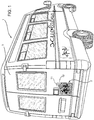
- Figure 1 shows a vehicle 1, in the case described above a school bus, with a signalling system 2 which can be attached to a wall 3 of the vehicle.
- the signalling system 2 is attached to a rear wall 3 of the vehicle.
- the signalling system 2 may be attached to the wall 3 by attachment means, for example threaded or glued means, or attached by means of a shaped mechanical coupling, not shown.
- the signalling system 2 comprises a frame 5 defining a closed shape, in the example above a square shape, and defining an inner volume 6 in which the following elements are housed.
- the signalling system 2 comprises a support element 7, preferably an element made of transparent material; for example, the support element 7 is made of plexiglass.
- the support element 7 comprises at least one LED 8, preferably two LED strips 8 housed in seats 9 cut out in the support element 7. Even more preferably, the two LED strips 8 are placed parallel to each other and extend along the height of the frame 5.
- At least one LED 8 is electrically connected to a control unit 11 by electrical connection elements 12, for example a wired connection.
- the control unit 11 is configured to control the lighting of the LED 8, preferably flashing it by powering it on at a predefined frequency.
- the control unit 11 may be the ECU of the vehicle 1.
- the signalling system 2 further comprises a film 10 made of electroluminescent material placed opposite the at least one LED 8.
- An electroluminescent material is a material which emits light without glare when an electric current or an electric field passes through it.
- the electroluminescent film 10 is electrically connected to the control unit 11 by electrical connection elements 13, for example a wired connection.
- the control unit 11 is configured to control the lighting of the electroluminescent film 10, preferably flashing it by powering it on, preferably at 12-24V, at a predefined frequency. Even more preferably, this frequency is the same lighting frequency as that of the at least one LED 8.
- the signalling system 2 also comprises a sticker 14, which can be attached to a surface of the electroluminescent film 10 opposite to that in front of the LED 8 and defining a silhouette 15 of a predefined shape.
- the sticker 14 is made of opaque material and the silhouette 15 is obtained via a corresponding shape cut in said opaque sticker 14.
- the signalling system 2 may further comprise an opaque layer 17, preferably a black film, configured to prevent light transmission from the strips 8 to the rear of the signalling system 2.
- the opaque layer 17 is preferably attached to a rear surface 7a of the support element 7 opposite to the surface in which the seats 9 are made.
- the signalling system 2 may also comprise a diffuser 18, preferably made of plexiglass or polarised glass to concentrate the light and interposed between the support element 7, opposite the at least one LED 8, and the electroluminescent film 10.
- the diffuser 18 is configured to diffuse and concentrate light from the LED 8 towards the electroluminescent film 10.
- the thickness of the frame 5, containing all the above-mentioned elements, is less than 2 mm, preferably between 1 and 2 mm.
- the signalling system 2 can be activated automatically, for example on the basis of a bus manoeuvre or on the basis of the activation of the bus turn signals, or manually according to the driver's wishes.
- the signalling system 2 When activated, the signalling system 2 makes it possible to signal to other drivers the silhouette 15 of the sticker 14 thanks to the light which passes through the shape cut in the sticker.
- the sticker can be changed by substituting it with another sticker 14 with a different silhouette 15.
- the silhouette of the sticker 14 is visible in all weather conditions and, furthermore, there is no longer the risk of dazzling drivers of other vehicles in the vicinity of the bus 1.
- the signalling system 2 can be attached anywhere on the exterior of one of the walls of the vehicle 1 since the light from the LED 8 and the film 10 is absorbed by the opaque layer 17.
- the signalling system 2 could also be attached to a side window of the vehicle 1.
- the frame 5 is also not thick; the frame 5 thus cannot interfere with the gauge of the vehicle 1.
- the frame 5 can be attached to and detached from one vehicle 1 and to/from another and, similarly, different stickers 14 could be applied in substitution for each other on the same signalling system 2.
- the signalling system 2 according to the present invention can also be assembled quickly and economically.
- the shape of the frame 5, the LED 8 and the sticker 14 could vary.
- the materials of the support element 7 or the diffuser 18 could be different.
Landscapes
- Engineering & Computer Science (AREA)
- Physics & Mathematics (AREA)
- General Engineering & Computer Science (AREA)
- Mechanical Engineering (AREA)
- Microelectronics & Electronic Packaging (AREA)
- Optics & Photonics (AREA)
- General Physics & Mathematics (AREA)
- Theoretical Computer Science (AREA)
- Business, Economics & Management (AREA)
- Accounting & Taxation (AREA)
- Marketing (AREA)
- Iron Core Of Rotating Electric Machines (AREA)
- Lighting Device Outwards From Vehicle And Optical Signal (AREA)
- Diaphragms For Electromechanical Transducers (AREA)
- Measuring Pulse, Heart Rate, Blood Pressure Or Blood Flow (AREA)
- Vehicle Interior And Exterior Ornaments, Soundproofing, And Insulation (AREA)
- Non-Portable Lighting Devices Or Systems Thereof (AREA)
Abstract
• a support element (7) configured to house at least one LED (8) connectable to a control unit (11) configured to power the at least one LED (8);
• an electroluminescent film (10) connectable to a control unit (11) configured to power the electroluminescent film (10);
• an opaque sticker (14) that shows a silhouette (15);
• a frame (5) configured to carry the support element (7) and the electroluminescent film (10),
according to the invention the electroluminescent film is arranged in front of the support element (7) and the opaque sticker (14) is attachable onto a surface of the electroluminescent film (10) opposite to the one arranged in front of the support element (7).

Description
- This Patent application claims priority from Italian Patent Application No.
10201800005869 filed on May 30, 2018 - The present invention concerns a signalling system for a vehicle, in particular a signalling system for the exterior of a public passenger transport vehicle.
- Some public passenger transport vehicles, for example buses for transporting children to school, comprise pictograms which alert other road vehicles to their presence and to potential danger; a school bus must stop frequently, and this stop must be signalled to other vehicles since children may emerge from the front of the vehicle.
- These pictograms were formerly reflective stickers glued to a wall, for example the rear wall, of the vehicle. However, when there is fog or rain this sticker may not be visible.
- This problem has been resolved by a regulatory evolution recommending the use of LEDs or OLEDs which can however dazzle drivers of other vehicles and furthermore do not succeed in clearly showing the shape of the pictogram in all possible atmospheric conditions.
- In order to reduce the risk of accidents, it is therefore necessary to improve vehicle signalling systems by making the silhouette of a desired pictogram visible in all possible visibility situations, without however dazzling the drivers of other vehicles.
- The invention aims to resolve the above-mentioned problems in an optimised and cost-effective way.
- The above-mentioned objects are achieved by a signalling system according to the attached Claims.
- Other characteristics and benefits of the invention will become apparent from the following non-limiting description, provided for illustrative purposes, with reference to the attached drawings wherein:
-
Figure 1 shows a vehicle comprising a signalling system according to the invention; -
Figure 2 is a perspective view of the signalling system according to the invention; and -
Figure 3 is an exploded perspective view of the system ofFigure 2 . -
Figure 1 shows avehicle 1, in the case described above a school bus, with asignalling system 2 which can be attached to awall 3 of the vehicle. In the case described above, thesignalling system 2 is attached to arear wall 3 of the vehicle. Thesignalling system 2 may be attached to thewall 3 by attachment means, for example threaded or glued means, or attached by means of a shaped mechanical coupling, not shown. - As better illustrated in
Figures 2 and 3 , thesignalling system 2 comprises aframe 5 defining a closed shape, in the example above a square shape, and defining aninner volume 6 in which the following elements are housed. - The
signalling system 2 comprises asupport element 7, preferably an element made of transparent material; for example, thesupport element 7 is made of plexiglass. - Beneficially, the
support element 7 comprises at least oneLED 8, preferably twoLED strips 8 housed inseats 9 cut out in thesupport element 7. Even more preferably, the twoLED strips 8 are placed parallel to each other and extend along the height of theframe 5. - At least one
LED 8 is electrically connected to acontrol unit 11 byelectrical connection elements 12, for example a wired connection. Thecontrol unit 11 is configured to control the lighting of theLED 8, preferably flashing it by powering it on at a predefined frequency. Thecontrol unit 11 may be the ECU of thevehicle 1. - According to the invention, the
signalling system 2 further comprises afilm 10 made of electroluminescent material placed opposite the at least oneLED 8. An electroluminescent material is a material which emits light without glare when an electric current or an electric field passes through it. - The
electroluminescent film 10 is electrically connected to thecontrol unit 11 byelectrical connection elements 13, for example a wired connection. Thecontrol unit 11 is configured to control the lighting of theelectroluminescent film 10, preferably flashing it by powering it on, preferably at 12-24V, at a predefined frequency. Even more preferably, this frequency is the same lighting frequency as that of the at least oneLED 8. - The
signalling system 2 also comprises asticker 14, which can be attached to a surface of theelectroluminescent film 10 opposite to that in front of theLED 8 and defining asilhouette 15 of a predefined shape. Beneficially, thesticker 14 is made of opaque material and thesilhouette 15 is obtained via a corresponding shape cut in saidopaque sticker 14. - The
signalling system 2 may further comprise anopaque layer 17, preferably a black film, configured to prevent light transmission from thestrips 8 to the rear of thesignalling system 2. Theopaque layer 17 is preferably attached to arear surface 7a of thesupport element 7 opposite to the surface in which theseats 9 are made. - The
signalling system 2 may also comprise adiffuser 18, preferably made of plexiglass or polarised glass to concentrate the light and interposed between thesupport element 7, opposite the at least oneLED 8, and theelectroluminescent film 10. Thediffuser 18 is configured to diffuse and concentrate light from theLED 8 towards theelectroluminescent film 10. - All the elements (
diffuser 18,opaque layer 17,electroluminescent film 10, support element 7) described above are housed inside thevolume 6 and have a shape complementary to that of theframe 5. It is further clear that they can be attached in a known way to the latter and to each other in a detachable way (to allow their replacement in case of malfunction). - The thickness of the
frame 5, containing all the above-mentioned elements, is less than 2 mm, preferably between 1 and 2 mm. - Operation of the
signalling system 2 according to the invention is as follows. - The
signalling system 2 can be activated automatically, for example on the basis of a bus manoeuvre or on the basis of the activation of the bus turn signals, or manually according to the driver's wishes. - When activated, the
signalling system 2 makes it possible to signal to other drivers thesilhouette 15 of thesticker 14 thanks to the light which passes through the shape cut in the sticker. - If necessary, the sticker can be changed by substituting it with another
sticker 14 with adifferent silhouette 15. - From the above, the benefits of a
signalling system 2 according to the present invention are very clear. - Thanks to the
signalling system 2, the silhouette of thesticker 14 is visible in all weather conditions and, furthermore, there is no longer the risk of dazzling drivers of other vehicles in the vicinity of thebus 1. - The risk of glare is also reduced thanks to use of the
diffuser 18. - The
signalling system 2 can be attached anywhere on the exterior of one of the walls of thevehicle 1 since the light from theLED 8 and thefilm 10 is absorbed by theopaque layer 17. For example, thesignalling system 2 could also be attached to a side window of thevehicle 1. - The
frame 5 is also not thick; theframe 5 thus cannot interfere with the gauge of thevehicle 1. - Furthermore, the
frame 5 can be attached to and detached from onevehicle 1 and to/from another and, similarly,different stickers 14 could be applied in substitution for each other on thesame signalling system 2. - The
signalling system 2 according to the present invention can also be assembled quickly and economically. - Finally, it is clear that the
signalling system 2 according to the present invention may be subject to modifications and variations without thereby departing from the protective scope defined by the Claims. - For example, the shape of the
frame 5, theLED 8 and thesticker 14 could vary. Furthermore, the materials of thesupport element 7 or thediffuser 18 could be different.
Claims (10)
- A signalling system (2) for the exterior of a vehicle (1), said system comprising:• a support element (7) configured to house at least one LED (8) connectable to a control unit (11) configured to power said LED (8);• an electroluminescent film (10) connectable to said control unit (11) configured to power said electroluminescent film (10);• an opaque sticker (14) that shows a silhouette (15);• a frame (5) configured to house said support element (7) and said electroluminescent film (10),said electroluminescent film (10) being arranged in front of said at least one LED (8) of said support element (7) and said opaque sticker (14) being attachable onto the surface of said electroluminescent film (10) opposite to the one placed in front of said at least one LED (8) of said support element (7).
- The signalling system according to Claim 1, characterised in that it comprises a diffuser element (18) interposed between the support element (7) and the electroluminescent film (10).
- The signalling system according to Claim 2, characterised in that said diffuser element (18) is made of plexiglass or polarised glass.
- The signalling system according to any one of Claims 1 to 3, characterised in that it comprises an opaque layer (17) coupled to a surface of said support element (7) opposite to the one placed in front of said electroluminescent film (10).
- The signalling system according to Claim 4, characterised in that said opaque layer (17) is a black film.
- The signalling system according to any one of the Claims 1 to 5, characterised in that said support element (7) is made of plexiglass.
- The signalling system according to any one of the Claims 1 to 6, characterised in that said silhouette (15) shown on said sticker (14) is obtained by cutting out a shape on an opaque sticker (14).
- The signalling system according to any one of the Claims 1 to 7, characterised in that it comprises two LED strips (8) parallel to one another.
- The signalling system according to any one of the Claims 1 to 8, characterised in that said frame (5) has a thickness ranging between 1 mm and 2 mm.
- A vehicle comprising a signalling system according to one of the preceding Claims.
Applications Claiming Priority (1)
| Application Number | Priority Date | Filing Date | Title |
|---|---|---|---|
| IT102018000005869A IT201800005869A1 (en) | 2018-05-30 | 2018-05-30 | SIGNALING SYSTEM FOR THE OUTSIDE OF A VEHICLE |
Publications (2)
| Publication Number | Publication Date |
|---|---|
| EP3575677A1 true EP3575677A1 (en) | 2019-12-04 |
| EP3575677B1 EP3575677B1 (en) | 2022-11-30 |
Family
ID=63312338
Family Applications (1)
| Application Number | Title | Priority Date | Filing Date |
|---|---|---|---|
| EP19177545.1A Active EP3575677B1 (en) | 2018-05-30 | 2019-05-30 | Signalling system for the exterior of a vehicle |
Country Status (3)
| Country | Link |
|---|---|
| EP (1) | EP3575677B1 (en) |
| ES (1) | ES2939135T3 (en) |
| IT (1) | IT201800005869A1 (en) |
Citations (7)
| Publication number | Priority date | Publication date | Assignee | Title |
|---|---|---|---|---|
| US5604480A (en) * | 1995-09-29 | 1997-02-18 | Transpec Inc. | Flashing caution/stop bus light assembly |
| JP2000255317A (en) * | 1999-03-10 | 2000-09-19 | Takaaki Makino | Bus vehicle device for indicating that passengers are getting on and off |
| US20070103922A1 (en) * | 2005-11-10 | 2007-05-10 | Rissmiller H B | Illuminated vehicle identification sign |
| US20090262545A1 (en) * | 2008-04-21 | 2009-10-22 | Joerg Amelung | Illumination Apparatus and Method of Producing a Planar Light Output |
| JP2012088624A (en) * | 2010-10-21 | 2012-05-10 | Denso Corp | Light-emitting display device |
| US20130027960A1 (en) * | 2010-03-05 | 2013-01-31 | Valeo Vision | Lighting and/or signaling device for a motor vehicle including a surface light source |
| JP2017220309A (en) * | 2016-06-03 | 2017-12-14 | 株式会社小糸製作所 | Light emitting device |
-
2018
- 2018-05-30 IT IT102018000005869A patent/IT201800005869A1/en unknown
-
2019
- 2019-05-30 EP EP19177545.1A patent/EP3575677B1/en active Active
- 2019-05-30 ES ES19177545T patent/ES2939135T3/en active Active
Patent Citations (7)
| Publication number | Priority date | Publication date | Assignee | Title |
|---|---|---|---|---|
| US5604480A (en) * | 1995-09-29 | 1997-02-18 | Transpec Inc. | Flashing caution/stop bus light assembly |
| JP2000255317A (en) * | 1999-03-10 | 2000-09-19 | Takaaki Makino | Bus vehicle device for indicating that passengers are getting on and off |
| US20070103922A1 (en) * | 2005-11-10 | 2007-05-10 | Rissmiller H B | Illuminated vehicle identification sign |
| US20090262545A1 (en) * | 2008-04-21 | 2009-10-22 | Joerg Amelung | Illumination Apparatus and Method of Producing a Planar Light Output |
| US20130027960A1 (en) * | 2010-03-05 | 2013-01-31 | Valeo Vision | Lighting and/or signaling device for a motor vehicle including a surface light source |
| JP2012088624A (en) * | 2010-10-21 | 2012-05-10 | Denso Corp | Light-emitting display device |
| JP2017220309A (en) * | 2016-06-03 | 2017-12-14 | 株式会社小糸製作所 | Light emitting device |
Also Published As
| Publication number | Publication date |
|---|---|
| IT201800005869A1 (en) | 2019-11-30 |
| ES2939135T3 (en) | 2023-04-19 |
| EP3575677B1 (en) | 2022-11-30 |
Similar Documents
| Publication | Publication Date | Title |
|---|---|---|
| US9087417B2 (en) | Window device with lighting for a motor vehicle | |
| US2010138A (en) | Lighting, signaling, and indicating accessory for motor vehicles | |
| US4758931A (en) | Vehicle light system | |
| US8950914B2 (en) | Lighting unit | |
| US20140321136A1 (en) | Lighting device with 3d-effect | |
| EP2789504A2 (en) | Warning device and method for vehicles | |
| BRPI1103797A2 (en) | roof rack assembly for a vehicle having a roof and an electric power supply | |
| KR20130044341A (en) | Signalling lamps for motor vehicle | |
| US20180202622A1 (en) | Flexible light bar assembly | |
| US20170259732A1 (en) | Mountable Vehicle Safety Light System | |
| US20160229336A1 (en) | U-Turn Safety Wireless Signal System | |
| KR20170022225A (en) | LED emergency lighting apparatus for vehicle | |
| EP2511135A1 (en) | Window arrangement | |
| EP3575677B1 (en) | Signalling system for the exterior of a vehicle | |
| US20050018444A1 (en) | Illuminated hazard warning light | |
| US1513769A (en) | Attachment for motor vehicles | |
| KR101305782B1 (en) | emergency signal apparatus for vehicles | |
| US20170057407A1 (en) | Courtesy Light | |
| US20170106795A1 (en) | Light Assembly | |
| EP3174760B1 (en) | Customizable modular lamp | |
| US6039448A (en) | Side rearview mirror device | |
| GB2274533A (en) | Signalling device in or for a motor vehicle. | |
| US3657821A (en) | Vehicle orienting device and method | |
| CN210502466U (en) | Device for driving lamp at night | |
| RU78973U1 (en) | DEVICE FOR COMMUNICATION OF DRIVERS OF VEHICLES DURING TRAFFIC |
Legal Events
| Date | Code | Title | Description |
|---|---|---|---|
| PUAI | Public reference made under article 153(3) epc to a published international application that has entered the european phase |
Free format text: ORIGINAL CODE: 0009012 |
|
| STAA | Information on the status of an ep patent application or granted ep patent |
Free format text: STATUS: THE APPLICATION HAS BEEN PUBLISHED |
|
| AK | Designated contracting states |
Kind code of ref document: A1 Designated state(s): AL AT BE BG CH CY CZ DE DK EE ES FI FR GB GR HR HU IE IS IT LI LT LU LV MC MK MT NL NO PL PT RO RS SE SI SK SM TR |
|
| AX | Request for extension of the european patent |
Extension state: BA ME |
|
| STAA | Information on the status of an ep patent application or granted ep patent |
Free format text: STATUS: REQUEST FOR EXAMINATION WAS MADE |
|
| 17P | Request for examination filed |
Effective date: 20200525 |
|
| RBV | Designated contracting states (corrected) |
Designated state(s): AL AT BE BG CH CY CZ DE DK EE ES FI FR GB GR HR HU IE IS IT LI LT LU LV MC MK MT NL NO PL PT RO RS SE SI SK SM TR |
|
| GRAP | Despatch of communication of intention to grant a patent |
Free format text: ORIGINAL CODE: EPIDOSNIGR1 |
|
| STAA | Information on the status of an ep patent application or granted ep patent |
Free format text: STATUS: GRANT OF PATENT IS INTENDED |
|
| INTG | Intention to grant announced |
Effective date: 20220623 |
|
| GRAS | Grant fee paid |
Free format text: ORIGINAL CODE: EPIDOSNIGR3 |
|
| GRAA | (expected) grant |
Free format text: ORIGINAL CODE: 0009210 |
|
| STAA | Information on the status of an ep patent application or granted ep patent |
Free format text: STATUS: THE PATENT HAS BEEN GRANTED |
|
| AK | Designated contracting states |
Kind code of ref document: B1 Designated state(s): AL AT BE BG CH CY CZ DE DK EE ES FI FR GB GR HR HU IE IS IT LI LT LU LV MC MK MT NL NO PL PT RO RS SE SI SK SM TR |
|
| REG | Reference to a national code |
Ref country code: CH Ref legal event code: EP Ref country code: GB Ref legal event code: FG4D |
|
| REG | Reference to a national code |
Ref country code: AT Ref legal event code: REF Ref document number: 1534935 Country of ref document: AT Kind code of ref document: T Effective date: 20221215 |
|
| REG | Reference to a national code |
Ref country code: IE Ref legal event code: FG4D |
|
| REG | Reference to a national code |
Ref country code: DE Ref legal event code: R096 Ref document number: 602019022435 Country of ref document: DE |
|
| REG | Reference to a national code |
Ref country code: LT Ref legal event code: MG9D |
|
| REG | Reference to a national code |
Ref country code: NL Ref legal event code: MP Effective date: 20221130 |
|
| REG | Reference to a national code |
Ref country code: ES Ref legal event code: FG2A Ref document number: 2939135 Country of ref document: ES Kind code of ref document: T3 Effective date: 20230419 |
|
| PG25 | Lapsed in a contracting state [announced via postgrant information from national office to epo] |
Ref country code: SE Free format text: LAPSE BECAUSE OF FAILURE TO SUBMIT A TRANSLATION OF THE DESCRIPTION OR TO PAY THE FEE WITHIN THE PRESCRIBED TIME-LIMIT Effective date: 20221130 Ref country code: PT Free format text: LAPSE BECAUSE OF FAILURE TO SUBMIT A TRANSLATION OF THE DESCRIPTION OR TO PAY THE FEE WITHIN THE PRESCRIBED TIME-LIMIT Effective date: 20230331 Ref country code: NO Free format text: LAPSE BECAUSE OF FAILURE TO SUBMIT A TRANSLATION OF THE DESCRIPTION OR TO PAY THE FEE WITHIN THE PRESCRIBED TIME-LIMIT Effective date: 20230228 Ref country code: LT Free format text: LAPSE BECAUSE OF FAILURE TO SUBMIT A TRANSLATION OF THE DESCRIPTION OR TO PAY THE FEE WITHIN THE PRESCRIBED TIME-LIMIT Effective date: 20221130 Ref country code: FI Free format text: LAPSE BECAUSE OF FAILURE TO SUBMIT A TRANSLATION OF THE DESCRIPTION OR TO PAY THE FEE WITHIN THE PRESCRIBED TIME-LIMIT Effective date: 20221130 |
|
| REG | Reference to a national code |
Ref country code: AT Ref legal event code: MK05 Ref document number: 1534935 Country of ref document: AT Kind code of ref document: T Effective date: 20221130 |
|
| PG25 | Lapsed in a contracting state [announced via postgrant information from national office to epo] |
Ref country code: RS Free format text: LAPSE BECAUSE OF FAILURE TO SUBMIT A TRANSLATION OF THE DESCRIPTION OR TO PAY THE FEE WITHIN THE PRESCRIBED TIME-LIMIT Effective date: 20221130 Ref country code: PL Free format text: LAPSE BECAUSE OF FAILURE TO SUBMIT A TRANSLATION OF THE DESCRIPTION OR TO PAY THE FEE WITHIN THE PRESCRIBED TIME-LIMIT Effective date: 20221130 Ref country code: LV Free format text: LAPSE BECAUSE OF FAILURE TO SUBMIT A TRANSLATION OF THE DESCRIPTION OR TO PAY THE FEE WITHIN THE PRESCRIBED TIME-LIMIT Effective date: 20221130 Ref country code: IS Free format text: LAPSE BECAUSE OF FAILURE TO SUBMIT A TRANSLATION OF THE DESCRIPTION OR TO PAY THE FEE WITHIN THE PRESCRIBED TIME-LIMIT Effective date: 20230330 Ref country code: HR Free format text: LAPSE BECAUSE OF FAILURE TO SUBMIT A TRANSLATION OF THE DESCRIPTION OR TO PAY THE FEE WITHIN THE PRESCRIBED TIME-LIMIT Effective date: 20221130 Ref country code: GR Free format text: LAPSE BECAUSE OF FAILURE TO SUBMIT A TRANSLATION OF THE DESCRIPTION OR TO PAY THE FEE WITHIN THE PRESCRIBED TIME-LIMIT Effective date: 20230301 |
|
| P01 | Opt-out of the competence of the unified patent court (upc) registered |
Effective date: 20230522 |
|
| PG25 | Lapsed in a contracting state [announced via postgrant information from national office to epo] |
Ref country code: NL Free format text: LAPSE BECAUSE OF FAILURE TO SUBMIT A TRANSLATION OF THE DESCRIPTION OR TO PAY THE FEE WITHIN THE PRESCRIBED TIME-LIMIT Effective date: 20221130 |
|
| PG25 | Lapsed in a contracting state [announced via postgrant information from national office to epo] |
Ref country code: SM Free format text: LAPSE BECAUSE OF FAILURE TO SUBMIT A TRANSLATION OF THE DESCRIPTION OR TO PAY THE FEE WITHIN THE PRESCRIBED TIME-LIMIT Effective date: 20221130 Ref country code: RO Free format text: LAPSE BECAUSE OF FAILURE TO SUBMIT A TRANSLATION OF THE DESCRIPTION OR TO PAY THE FEE WITHIN THE PRESCRIBED TIME-LIMIT Effective date: 20221130 Ref country code: EE Free format text: LAPSE BECAUSE OF FAILURE TO SUBMIT A TRANSLATION OF THE DESCRIPTION OR TO PAY THE FEE WITHIN THE PRESCRIBED TIME-LIMIT Effective date: 20221130 Ref country code: DK Free format text: LAPSE BECAUSE OF FAILURE TO SUBMIT A TRANSLATION OF THE DESCRIPTION OR TO PAY THE FEE WITHIN THE PRESCRIBED TIME-LIMIT Effective date: 20221130 Ref country code: CZ Free format text: LAPSE BECAUSE OF FAILURE TO SUBMIT A TRANSLATION OF THE DESCRIPTION OR TO PAY THE FEE WITHIN THE PRESCRIBED TIME-LIMIT Effective date: 20221130 Ref country code: AT Free format text: LAPSE BECAUSE OF FAILURE TO SUBMIT A TRANSLATION OF THE DESCRIPTION OR TO PAY THE FEE WITHIN THE PRESCRIBED TIME-LIMIT Effective date: 20221130 |
|
| PG25 | Lapsed in a contracting state [announced via postgrant information from national office to epo] |
Ref country code: SK Free format text: LAPSE BECAUSE OF FAILURE TO SUBMIT A TRANSLATION OF THE DESCRIPTION OR TO PAY THE FEE WITHIN THE PRESCRIBED TIME-LIMIT Effective date: 20221130 Ref country code: AL Free format text: LAPSE BECAUSE OF FAILURE TO SUBMIT A TRANSLATION OF THE DESCRIPTION OR TO PAY THE FEE WITHIN THE PRESCRIBED TIME-LIMIT Effective date: 20221130 |
|
| REG | Reference to a national code |
Ref country code: DE Ref legal event code: R097 Ref document number: 602019022435 Country of ref document: DE |
|
| PLBE | No opposition filed within time limit |
Free format text: ORIGINAL CODE: 0009261 |
|
| STAA | Information on the status of an ep patent application or granted ep patent |
Free format text: STATUS: NO OPPOSITION FILED WITHIN TIME LIMIT |
|
| 26N | No opposition filed |
Effective date: 20230831 |
|
| PG25 | Lapsed in a contracting state [announced via postgrant information from national office to epo] |
Ref country code: SI Free format text: LAPSE BECAUSE OF FAILURE TO SUBMIT A TRANSLATION OF THE DESCRIPTION OR TO PAY THE FEE WITHIN THE PRESCRIBED TIME-LIMIT Effective date: 20221130 |
|
| REG | Reference to a national code |
Ref country code: CH Ref legal event code: PL |
|
| PG25 | Lapsed in a contracting state [announced via postgrant information from national office to epo] |
Ref country code: MC Free format text: LAPSE BECAUSE OF FAILURE TO SUBMIT A TRANSLATION OF THE DESCRIPTION OR TO PAY THE FEE WITHIN THE PRESCRIBED TIME-LIMIT Effective date: 20221130 |
|
| GBPC | Gb: european patent ceased through non-payment of renewal fee |
Effective date: 20230530 |
|
| REG | Reference to a national code |
Ref country code: BE Ref legal event code: MM Effective date: 20230531 |
|
| PG25 | Lapsed in a contracting state [announced via postgrant information from national office to epo] |
Ref country code: MC Free format text: LAPSE BECAUSE OF FAILURE TO SUBMIT A TRANSLATION OF THE DESCRIPTION OR TO PAY THE FEE WITHIN THE PRESCRIBED TIME-LIMIT Effective date: 20221130 Ref country code: LU Free format text: LAPSE BECAUSE OF NON-PAYMENT OF DUE FEES Effective date: 20230530 Ref country code: LI Free format text: LAPSE BECAUSE OF NON-PAYMENT OF DUE FEES Effective date: 20230531 Ref country code: CH Free format text: LAPSE BECAUSE OF NON-PAYMENT OF DUE FEES Effective date: 20230531 |
|
| REG | Reference to a national code |
Ref country code: IE Ref legal event code: MM4A |
|
| PG25 | Lapsed in a contracting state [announced via postgrant information from national office to epo] |
Ref country code: IE Free format text: LAPSE BECAUSE OF NON-PAYMENT OF DUE FEES Effective date: 20230530 |
|
| PG25 | Lapsed in a contracting state [announced via postgrant information from national office to epo] |
Ref country code: IE Free format text: LAPSE BECAUSE OF NON-PAYMENT OF DUE FEES Effective date: 20230530 Ref country code: GB Free format text: LAPSE BECAUSE OF NON-PAYMENT OF DUE FEES Effective date: 20230530 |
|
| PG25 | Lapsed in a contracting state [announced via postgrant information from national office to epo] |
Ref country code: BE Free format text: LAPSE BECAUSE OF NON-PAYMENT OF DUE FEES Effective date: 20230531 |
|
| PG25 | Lapsed in a contracting state [announced via postgrant information from national office to epo] |
Ref country code: BG Free format text: LAPSE BECAUSE OF FAILURE TO SUBMIT A TRANSLATION OF THE DESCRIPTION OR TO PAY THE FEE WITHIN THE PRESCRIBED TIME-LIMIT Effective date: 20221130 |
|
| PG25 | Lapsed in a contracting state [announced via postgrant information from national office to epo] |
Ref country code: BG Free format text: LAPSE BECAUSE OF FAILURE TO SUBMIT A TRANSLATION OF THE DESCRIPTION OR TO PAY THE FEE WITHIN THE PRESCRIBED TIME-LIMIT Effective date: 20221130 |
|
| PGFP | Annual fee paid to national office [announced via postgrant information from national office to epo] |
Ref country code: DE Payment date: 20250528 Year of fee payment: 7 |
|
| PGFP | Annual fee paid to national office [announced via postgrant information from national office to epo] |
Ref country code: ES Payment date: 20250612 Year of fee payment: 7 |
|
| PGFP | Annual fee paid to national office [announced via postgrant information from national office to epo] |
Ref country code: IT Payment date: 20250512 Year of fee payment: 7 |
|
| PGFP | Annual fee paid to national office [announced via postgrant information from national office to epo] |
Ref country code: FR Payment date: 20250526 Year of fee payment: 7 |
|
| PG25 | Lapsed in a contracting state [announced via postgrant information from national office to epo] |
Ref country code: CY Free format text: LAPSE BECAUSE OF FAILURE TO SUBMIT A TRANSLATION OF THE DESCRIPTION OR TO PAY THE FEE WITHIN THE PRESCRIBED TIME-LIMIT; INVALID AB INITIO Effective date: 20190530 |
|
| PG25 | Lapsed in a contracting state [announced via postgrant information from national office to epo] |
Ref country code: HU Free format text: LAPSE BECAUSE OF FAILURE TO SUBMIT A TRANSLATION OF THE DESCRIPTION OR TO PAY THE FEE WITHIN THE PRESCRIBED TIME-LIMIT; INVALID AB INITIO Effective date: 20190530 |
|
| PG25 | Lapsed in a contracting state [announced via postgrant information from national office to epo] |
Ref country code: TR Free format text: LAPSE BECAUSE OF FAILURE TO SUBMIT A TRANSLATION OF THE DESCRIPTION OR TO PAY THE FEE WITHIN THE PRESCRIBED TIME-LIMIT Effective date: 20221130 |