EP3575647A1 - Capacity control valve - Google Patents
Capacity control valve Download PDFInfo
- Publication number
- EP3575647A1 EP3575647A1 EP18744644.8A EP18744644A EP3575647A1 EP 3575647 A1 EP3575647 A1 EP 3575647A1 EP 18744644 A EP18744644 A EP 18744644A EP 3575647 A1 EP3575647 A1 EP 3575647A1
- Authority
- EP
- European Patent Office
- Prior art keywords
- valve
- chamber
- pressure
- communication passage
- chamber pressure
- Prior art date
- Legal status (The legal status is an assumption and is not a legal conclusion. Google has not performed a legal analysis and makes no representation as to the accuracy of the status listed.)
- Granted
Links
Images


Classifications
-
- F—MECHANICAL ENGINEERING; LIGHTING; HEATING; WEAPONS; BLASTING
- F16—ENGINEERING ELEMENTS AND UNITS; GENERAL MEASURES FOR PRODUCING AND MAINTAINING EFFECTIVE FUNCTIONING OF MACHINES OR INSTALLATIONS; THERMAL INSULATION IN GENERAL
- F16K—VALVES; TAPS; COCKS; ACTUATING-FLOATS; DEVICES FOR VENTING OR AERATING
- F16K31/00—Actuating devices; Operating means; Releasing devices
- F16K31/02—Actuating devices; Operating means; Releasing devices electric; magnetic
- F16K31/06—Actuating devices; Operating means; Releasing devices electric; magnetic using a magnet, e.g. diaphragm valves, cutting off by means of a liquid
- F16K31/0603—Multiple-way valves
- F16K31/0624—Lift valves
-
- F—MECHANICAL ENGINEERING; LIGHTING; HEATING; WEAPONS; BLASTING
- F04—POSITIVE - DISPLACEMENT MACHINES FOR LIQUIDS; PUMPS FOR LIQUIDS OR ELASTIC FLUIDS
- F04B—POSITIVE-DISPLACEMENT MACHINES FOR LIQUIDS; PUMPS
- F04B27/00—Multi-cylinder pumps specially adapted for elastic fluids and characterised by number or arrangement of cylinders
- F04B27/08—Multi-cylinder pumps specially adapted for elastic fluids and characterised by number or arrangement of cylinders having cylinders coaxial with, or parallel or inclined to, main shaft axis
- F04B27/14—Control
- F04B27/16—Control of pumps with stationary cylinders
- F04B27/18—Control of pumps with stationary cylinders by varying the relative positions of a swash plate and a cylinder block
- F04B27/1804—Controlled by crankcase pressure
-
- F—MECHANICAL ENGINEERING; LIGHTING; HEATING; WEAPONS; BLASTING
- F04—POSITIVE - DISPLACEMENT MACHINES FOR LIQUIDS; PUMPS FOR LIQUIDS OR ELASTIC FLUIDS
- F04B—POSITIVE-DISPLACEMENT MACHINES FOR LIQUIDS; PUMPS
- F04B27/00—Multi-cylinder pumps specially adapted for elastic fluids and characterised by number or arrangement of cylinders
- F04B27/08—Multi-cylinder pumps specially adapted for elastic fluids and characterised by number or arrangement of cylinders having cylinders coaxial with, or parallel or inclined to, main shaft axis
- F04B27/14—Control
- F04B27/20—Control of pumps with rotary cylinder block
- F04B27/22—Control of pumps with rotary cylinder block by varying the relative positions of a swash plate and a cylinder block
-
- F—MECHANICAL ENGINEERING; LIGHTING; HEATING; WEAPONS; BLASTING
- F16—ENGINEERING ELEMENTS AND UNITS; GENERAL MEASURES FOR PRODUCING AND MAINTAINING EFFECTIVE FUNCTIONING OF MACHINES OR INSTALLATIONS; THERMAL INSULATION IN GENERAL
- F16K—VALVES; TAPS; COCKS; ACTUATING-FLOATS; DEVICES FOR VENTING OR AERATING
- F16K11/00—Multiple-way valves, e.g. mixing valves; Pipe fittings incorporating such valves
- F16K11/02—Multiple-way valves, e.g. mixing valves; Pipe fittings incorporating such valves with all movable sealing faces moving as one unit
-
- F—MECHANICAL ENGINEERING; LIGHTING; HEATING; WEAPONS; BLASTING
- F16—ENGINEERING ELEMENTS AND UNITS; GENERAL MEASURES FOR PRODUCING AND MAINTAINING EFFECTIVE FUNCTIONING OF MACHINES OR INSTALLATIONS; THERMAL INSULATION IN GENERAL
- F16K—VALVES; TAPS; COCKS; ACTUATING-FLOATS; DEVICES FOR VENTING OR AERATING
- F16K11/00—Multiple-way valves, e.g. mixing valves; Pipe fittings incorporating such valves
- F16K11/02—Multiple-way valves, e.g. mixing valves; Pipe fittings incorporating such valves with all movable sealing faces moving as one unit
- F16K11/04—Multiple-way valves, e.g. mixing valves; Pipe fittings incorporating such valves with all movable sealing faces moving as one unit comprising only lift valves
-
- F—MECHANICAL ENGINEERING; LIGHTING; HEATING; WEAPONS; BLASTING
- F04—POSITIVE - DISPLACEMENT MACHINES FOR LIQUIDS; PUMPS FOR LIQUIDS OR ELASTIC FLUIDS
- F04B—POSITIVE-DISPLACEMENT MACHINES FOR LIQUIDS; PUMPS
- F04B27/00—Multi-cylinder pumps specially adapted for elastic fluids and characterised by number or arrangement of cylinders
- F04B27/08—Multi-cylinder pumps specially adapted for elastic fluids and characterised by number or arrangement of cylinders having cylinders coaxial with, or parallel or inclined to, main shaft axis
- F04B27/14—Control
- F04B27/16—Control of pumps with stationary cylinders
- F04B27/18—Control of pumps with stationary cylinders by varying the relative positions of a swash plate and a cylinder block
- F04B27/1804—Controlled by crankcase pressure
- F04B2027/1822—Valve-controlled fluid connection
- F04B2027/1827—Valve-controlled fluid connection between crankcase and discharge chamber
-
- F—MECHANICAL ENGINEERING; LIGHTING; HEATING; WEAPONS; BLASTING
- F04—POSITIVE - DISPLACEMENT MACHINES FOR LIQUIDS; PUMPS FOR LIQUIDS OR ELASTIC FLUIDS
- F04B—POSITIVE-DISPLACEMENT MACHINES FOR LIQUIDS; PUMPS
- F04B27/00—Multi-cylinder pumps specially adapted for elastic fluids and characterised by number or arrangement of cylinders
- F04B27/08—Multi-cylinder pumps specially adapted for elastic fluids and characterised by number or arrangement of cylinders having cylinders coaxial with, or parallel or inclined to, main shaft axis
- F04B27/14—Control
- F04B27/16—Control of pumps with stationary cylinders
- F04B27/18—Control of pumps with stationary cylinders by varying the relative positions of a swash plate and a cylinder block
- F04B27/1804—Controlled by crankcase pressure
- F04B2027/1822—Valve-controlled fluid connection
- F04B2027/1831—Valve-controlled fluid connection between crankcase and suction chamber
-
- F—MECHANICAL ENGINEERING; LIGHTING; HEATING; WEAPONS; BLASTING
- F04—POSITIVE - DISPLACEMENT MACHINES FOR LIQUIDS; PUMPS FOR LIQUIDS OR ELASTIC FLUIDS
- F04B—POSITIVE-DISPLACEMENT MACHINES FOR LIQUIDS; PUMPS
- F04B27/00—Multi-cylinder pumps specially adapted for elastic fluids and characterised by number or arrangement of cylinders
- F04B27/08—Multi-cylinder pumps specially adapted for elastic fluids and characterised by number or arrangement of cylinders having cylinders coaxial with, or parallel or inclined to, main shaft axis
- F04B27/14—Control
- F04B27/16—Control of pumps with stationary cylinders
- F04B27/18—Control of pumps with stationary cylinders by varying the relative positions of a swash plate and a cylinder block
- F04B27/1804—Controlled by crankcase pressure
- F04B2027/184—Valve controlling parameter
- F04B2027/1845—Crankcase pressure
-
- F—MECHANICAL ENGINEERING; LIGHTING; HEATING; WEAPONS; BLASTING
- F04—POSITIVE - DISPLACEMENT MACHINES FOR LIQUIDS; PUMPS FOR LIQUIDS OR ELASTIC FLUIDS
- F04B—POSITIVE-DISPLACEMENT MACHINES FOR LIQUIDS; PUMPS
- F04B27/00—Multi-cylinder pumps specially adapted for elastic fluids and characterised by number or arrangement of cylinders
- F04B27/08—Multi-cylinder pumps specially adapted for elastic fluids and characterised by number or arrangement of cylinders having cylinders coaxial with, or parallel or inclined to, main shaft axis
- F04B27/14—Control
- F04B27/16—Control of pumps with stationary cylinders
- F04B27/18—Control of pumps with stationary cylinders by varying the relative positions of a swash plate and a cylinder block
- F04B27/1804—Controlled by crankcase pressure
- F04B2027/184—Valve controlling parameter
- F04B2027/185—Discharge pressure
-
- F—MECHANICAL ENGINEERING; LIGHTING; HEATING; WEAPONS; BLASTING
- F04—POSITIVE - DISPLACEMENT MACHINES FOR LIQUIDS; PUMPS FOR LIQUIDS OR ELASTIC FLUIDS
- F04B—POSITIVE-DISPLACEMENT MACHINES FOR LIQUIDS; PUMPS
- F04B27/00—Multi-cylinder pumps specially adapted for elastic fluids and characterised by number or arrangement of cylinders
- F04B27/08—Multi-cylinder pumps specially adapted for elastic fluids and characterised by number or arrangement of cylinders having cylinders coaxial with, or parallel or inclined to, main shaft axis
- F04B27/14—Control
- F04B27/16—Control of pumps with stationary cylinders
- F04B27/18—Control of pumps with stationary cylinders by varying the relative positions of a swash plate and a cylinder block
- F04B27/1804—Controlled by crankcase pressure
- F04B2027/184—Valve controlling parameter
- F04B2027/1859—Suction pressure
-
- F—MECHANICAL ENGINEERING; LIGHTING; HEATING; WEAPONS; BLASTING
- F16—ENGINEERING ELEMENTS AND UNITS; GENERAL MEASURES FOR PRODUCING AND MAINTAINING EFFECTIVE FUNCTIONING OF MACHINES OR INSTALLATIONS; THERMAL INSULATION IN GENERAL
- F16K—VALVES; TAPS; COCKS; ACTUATING-FLOATS; DEVICES FOR VENTING OR AERATING
- F16K31/00—Actuating devices; Operating means; Releasing devices
- F16K31/02—Actuating devices; Operating means; Releasing devices electric; magnetic
- F16K31/06—Actuating devices; Operating means; Releasing devices electric; magnetic using a magnet, e.g. diaphragm valves, cutting off by means of a liquid
Definitions
- the present invention relates to a capacity control valve for variably controlling the capacity or pressure of a working fluid, and particularly relates to a capacity control valve for controlling, in accordance with a pressure load, the discharge rate of a variable capacity compressor or the like suitable for an air conditioning system of an automobile or the like.
- a swash plate type variable capacity compressor suitable for an air-conditioning system of an automobile or the like includes a rotating shaft rotationally driven by a rotational force of an engine, a swash plate coupled to the rotating shaft such that the plate's angle of inclination can be varied, a piston for compression coupled to the swash plate, and the like.
- the compressor controls the discharge rate of a refrigerant gas.
- the angle of inclination of the swash plate can be continuously varied by appropriately controlling the pressure inside the control chamber using a capacity control valve that is opened and closed by electromagnetic force, and thereby regulating the balance of pressures acting on opposite faces of the piston, while utilizing a suction pressure of a suction chamber for drawing in the refrigerant, a discharge pressure of a discharge chamber for discharging the refrigerant pressurized by the piston, and a control chamber pressure of a control chamber (a crank chamber) in which the swash plate is housed.
- a valve is known that includes a second communication passage 173 and a valve hole 177 providing communication between a discharge chamber and a control chamber; a second valve chamber 182 formed in the middle of a discharge-side passage; a third communication passage 171 and a flow channel 172 providing communication between a suction chamber and the control chamber; a third valve chamber 183 formed in the middle of a suction-side passage; a valve element 181 formed such that a second valve portion 176, disposed in the second valve chamber 182 and opening and closing the second communication passage 173 and the valve hole 177, and a third valve portion 175, disposed in the third valve chamber 183 and opening and closing the third communication passage 171 and the flow channel 172, move in reciprocating motion as a single unit, with one of the second valve portion 176 and the third valve portion 175 performing its opening operation at the same time that the other performs its closing operation; a first valve chamber 184 formed near the control chamber; a first valve chamber 184 formed near the control chamber; a first valve chamber 184
- a capacity control valve 170 is able to adjust the pressure inside the control chamber (the control chamber pressure) by making the discharge chamber and the control chamber communicate with one another.
- the capacity control valve 170 is also configured such that, in a case where the control chamber pressure Pc has increased while the variable capacity compressor is in a stopped state, the first valve portion (the valve opening coupling portion) 179 disengages from the valve seat body (the engaging portion) 180, thereby opening the suction-side passage and making the suction chamber and the control chamber communicate with one another.
- liquefied refrigerant (refrigerant gas that has been liquefied by cooling while the compressor is inoperative) accumulates in the control chamber (the crank chamber).
- the refrigerant gas cannot be compressed when the compressor is restarted, and the pre-set discharge rate cannot be ensured.
- the desired capacity control it is necessary for the liquefied refrigerant to be discharged from the control chamber (the crank chamber) as quickly as possible.
- the conventional art described above is configured such that an auxiliary communication passage 179 is provided in the valve seat body (the engaging portion) 180, thereby making communication possible from the first valve chamber 184, through the auxiliary communication passage 185, an intermediate communication passage 186, and the flow channel 172, to the third communication passage 171, which is in a state of being at the suction chamber pressure.
- the variable capacity compressor is started for cooling
- the liquefied refrigerant is discharged from the control chamber (the crank chamber) to the suction chamber, as shown by the arrow in FIG. 8 , thereby vaporizing the refrigerant liquid in the control chamber.
- This enables the compressor to be brought into a cooling operation in from one-fifteenth to one-tenth the time required by a capacity control valve in which the auxiliary communication passage 185 is not provided.
- FIG. 8 shows a state in which electric current is supplied to the solenoid S, release spring means 187 has contracted, and the third valve portion 175 has opened.
- the release spring means 187 extends, such that the third valve portion 175 closes, the second valve portion 176 is brought into an open state, and the first valve portion 179 opens under the suction chamber pressure Ps and the control chamber pressure Pc.
- the refrigerant liquid in the control chamber vaporizes, and fluid under the control chamber pressure Pc flows from a first communication passage 174 to the first valve chamber 184.
- the suction chamber pressure Ps and the control chamber pressure Pc are high, such that the pressure-sensitive element (the bellows) 178 contracts and a gap opens between the first valve portion 179 and the valve seat body 180.
- the size of the opening between the first valve portion 179 and the valve seat body 180 is functionally restricted, so the vaporization of the refrigerant liquid in the first valve chamber 184 is accelerated only slightly by the opening of the valve. Accordingly, the refrigerant liquid in the control chamber can be made to vaporize much faster by providing the auxiliary communication passage 185, which communicates with the intermediate communication passage 186.
- the refrigerant gas which is determined by the area S1 of the auxiliary communication passage 185, flows from the control chamber to the suction chamber in the entire control region, and the flow of the refrigerant gas is not restricted until the valve element 181 passes the position of the stroke Lm in the control region and approaches the maximum stroke L. Therefore, a decrease in the operating efficiency of the variable capacity compressor is unavoidable while the control is being performed.
- Patent Document 1 JP 5167121 B
- the present invention provides a capacity control valve having an auxiliary communication passage to be improved in the function for discharging a liquefied refrigerant from a control chamber when a variable capacity compressor is started, the capacity control valve also shortening the start-up time for the variable capacity compressor and improving both the operating efficiency and the control responsiveness when control is being performed.
- a capacity control valve of the present invention is a capacity control valve controlling, in accordance with a degree of opening of a valve portion, a flow rate or a pressure inside an operation control chamber.
- the capacity control valve includes a valve body, a pressure-sensitive element, a valve element, a solenoid portion, and a throttle valve portion.
- the valve body has a first valve chamber, a second valve chamber, and a third valve chamber, the first valve chamber communicating with a first communication passage, through which a fluid under a control chamber pressure passes, and having a first valve seat face and a second valve seat face, the second valve chamber having a first valve hole, which communicates with the first communication passage, and communicating with a second communication passage, through which a fluid under a discharge chamber pressure passes, and the third valve chamber communicate with a third communication passage, through which a fluid under a suction chamber pressure passes.
- the pressure-sensitive element is disposed in the third valve chamber, extending and contracting in reaction to the suction chamber pressure and having a third valve seat face disposed on an extending and contracting free end.
- the valve element has an intermediate communication passage, a second valve portion, a first valve portion, and a third valve portion, the intermediate communication passage allowing the first valve chamber and the third valve chamber to communicate with one another through an auxiliary communication passage, the second valve portion opening and closing the first valve hole by separating from and coming into contact with the second valve seat face, the first valve hole allowing the first valve chamber and the second valve chamber to communicate with one another, the first valve portion opening and closing the auxiliary communication passage by moving in conjunction with and in the opposite direction from the second valve portion, and the third valve portion opening and closing the intermediate communication passage and the third valve chamber by separating from and coming into contact with the third valve seat face.
- the solenoid portion is attached to the valve body and has an electromagnetic coil portion, a plunger, a stator core, and a rod connecting the plunger to the valve element, the solenoid portion operating to open and close the individual valve portions of the valve element in accordance with an electric current flowing through the electromagnetic coil portion.
- the throttle valve portion has a communication hole, disposed between the second valve portion and the third valve portion and allowing the intermediate communication passage and the third valve chamber to communicate with one another, and a second valve hole, disposed between the second valve chamber and the third valve chamber.
- An amount of narrowing of the throttle valve portion in relation to a stroke of the valve element is large during an initial valve opening, when the second valve portion separates from the second valve seat face, and becomes smaller after the initial valve opening.
- the variable capacity compressor when the variable capacity compressor operates to discharge the liquefied refrigerant, the liquefied refrigerant is discharged to the suction chamber through the third valve portion and the communication hole, both of which communicate with the intermediate communication passage, making it possible for the liquefied refrigerant to be discharged in a short period of time.
- the control chamber pressure and the suction chamber pressure decrease, the third valve portion closes, and the second valve portion starts to open, shifting the variable capacity compressor to control operation.
- the throttle valve portion significantly narrows the communication hole, so the flow of a refrigerant gas through the communication hole from the control chamber to the suction chamber is greatly throttled, making it possible to prevent a deterioration in the operating efficiency of the variable capacity compressor.
- the valve body is provided with an induction hole making the third valve chamber and the solenoid portion communicate with one another to regulate the sensitivity of the control chamber pressure to changes in the suction chamber pressure.
- the suction chamber pressure of the variable capacity compressor can be made to revert quickly to the set pressure.
- a gap portion between the rod and the stator core of the solenoid portion is provided with a clearance seal portion regulating the sensitivity of the control chamber pressure to changes in the suction chamber pressure.
- the sensitivity of the control chamber pressure to changes in the suction chamber pressure can be adjusted by regulating the clearance seal portion, making it possible to match the capacity control valve to the properties of the variable capacity compressor.
- a gap portion between the valve element and the stator core of the solenoid portion is provided with a clearance seal portion regulating the sensitivity of the control chamber pressure to changes in the suction chamber pressure.
- the sensitivity of the control chamber pressure to changes in the suction chamber pressure can be adjusted by regulating the clearance seal portion, making it possible to match the capacity control valve to the properties of the variable capacity compressor.
- a capacity control valve of the present invention is a capacity control valve controlling, in accordance with a degree of opening of a valve portion, one of a flow rate and a pressure inside an operation control chamber.
- the capacity control valve includes a valve body, a pressure-sensitive element, a valve element, a solenoid portion, and a throttle valve portion.
- the valve body has a first valve chamber, a second valve chamber, and a third valve chamber, the first valve chamber communicating with a first communication passage, through which a fluid under a discharge chamber pressure passes, and having a second valve seat face, the second valve chamber having a first valve hole, which communicates with the first communication passage, and communicating with a second communication passage, through which a fluid under a control chamber pressure passes, and the third valve chamber communicating with a third communication passage, through which a fluid under a suction chamber pressure passes.
- the pressure-sensitive element is disposed in the third valve chamber, extending and contracting in reaction to the suction chamber pressure and having a third valve seat face disposed on an extending and contracting free end.
- the valve element has a second valve portion, an intermediate communication passage, and a third valve portion, the second valve portion opening and closing the first valve hole by separating from and coming into contact with the second valve seat face, the first valve hole allowing the first valve chamber and the second valve chamber to communicate with one another, the intermediate communication passage allowing the second valve chamber and the third valve chamber to communicate with one another through an auxiliary communication passage, and the third valve portion opening and closing the third valve seat face, which allows the intermediate communication passage and the third valve chamber to communicate with one another.
- the solenoid portion is attached to the valve body and has an electromagnetic coil portion, a plunger, a stator core, and a rod connecting the plunger to the valve element, the solenoid portion operating to open and close the individual valve portions of the valve element in accordance with an electric current flowing through the electromagnetic coil portion.
- the throttle valve portion has a communication hole, disposed between the second valve portion and the third valve portion and allowing the intermediate communication passage and the third valve chamber to communicate with one another, and a second valve hole, disposed between the second valve chamber and the third valve chamber.
- An amount of narrowing of the throttle valve portion in relation to a stroke of the valve element is large during an initial valve opening, when the second valve portion separates from the second valve seat face, and becomes smaller after the initial valve opening.
- the variable capacity compressor when the variable capacity compressor operates to discharge the liquefied refrigerant, the liquefied refrigerant is discharged to the suction chamber through the third valve portion and the communication hole, both of which communicate with the intermediate communication passage, making it possible for the liquefied refrigerant to be discharged in a short period of time.
- the control chamber pressure and the suction chamber pressure decrease, the third valve portion closes, and the second valve portion starts to open, shifting the variable capacity compressor to control operation.
- the throttle valve portion significantly narrows the communication hole, so a refrigerant gas through the communication hole from the control chamber to the suction chamber is greatly throttled, making it possible to prevent a deterioration in the operating efficiency of the variable capacity compressor.
- the valve body is provided with an induction hole making the third valve chamber and the solenoid portion communicate with one another to regulate the sensitivity of the control chamber pressure to changes in the suction chamber pressure.
- the suction chamber pressure of the variable capacity compressor can be made to revert quickly to a set suction chamber pressure.
- a gap portion between the rod and the stator core of the solenoid portion is provided with a clearance seal portion regulating the sensitivity of the control chamber pressure to changes in the suction chamber pressure.
- the sensitivity of the control chamber pressure to changes in the suction chamber pressure can be adjusted by regulating the clearance seal portion, making it possible to match the capacity control valve to the properties of the variable capacity compressor.
- a gap portion between the valve element and the stator core of the solenoid portion is provided with a clearance seal portion regulating the sensitivity of the control chamber pressure to changes in the suction chamber pressure.
- the sensitivity of the control chamber pressure to changes in the suction chamber pressure can be adjusted by regulating the clearance seal portion, making it possible to match the capacity control valve to the properties of the variable capacity compressor.
- FIG. 1 the reference numeral 1 refers to the capacity control valve.
- the capacity control valve 1 mainly includes a valve body 2, a valve element 21, a pressure-sensitive element 22, and a solenoid portion 30.
- the components of the capacity control valve 1 will be explained individually.
- the valve body 2 includes a first valve body 2A and a second valve body 2B, the first valve body 2A having a functioning through-hole in its interior and the second valve body 2B integrally fitted to one end of the first valve body 2A.
- the first valve body 2A may be composed of a metal such as brass, iron, aluminum, stainless steel, or the like, or from a synthetic resin or the like.
- the second valve body 2B because it functions as a magnetic path for the solenoid portion 30, is composed of a magnetic material with low magnetic reluctance, such as iron or the like. Because it differs from the first valve body 2A in both its material and function, the second valve body 2B is provided as a separate component from the first valve body 2A. As long as this point is taken into consideration, the shape of the second valve body 2B shown in FIG. 1 may be modified as desired.
- the first valve body 2A is a hollow cylindrical member having a through-hole extending through it in the axial direction, with a third valve chamber 4, a second valve chamber 6, and a first valve chamber 7 being continuously provided in sections of the through-hole.
- the third valve chamber 4 is formed in a section at one end of the through-hole
- the second valve chamber 6 is continuously provided adjacent to the third valve chamber 4 on the side of the solenoid portion 30 of the third valve chamber 4
- the first valve chamber 7 is continuously provided adjacent to the second valve chamber 6 on the side of the solenoid portion 30 of the second valve chamber 6.
- a second valve hole 12A is continuously provided between the third valve chamber 4 and the second valve chamber 6, its diameter being smaller than the diameters of the second and third valve chambers.
- a first valve hole 5 is continuously provided between the second valve chamber 6 and the first valve chamber 7, its diameter being smaller than the diameters of the second and first valve chambers, and a second valve seat face 6A is provided around the first valve hole 5 on the side of the first valve chamber 7.
- Third communication passages 9 are connected to the third valve chamber 4.
- the third communication passages 9 communicate with a suction chamber of a variable capacity compressor (not shown) and are configured such that the capacity control valve 1 can cause a fluid under a suction chamber pressure Ps to flow into and out of the third valve chamber 4.
- Second communication passages 8 are connected to the second valve chamber 6.
- the second communication passages 8 communicate with a discharge chamber of the variable capacity compressor and are configured such that the capacity control valve 1 can allow a volume of a fluid under a discharge chamber pressure Pd to flow into a control chamber.
- First communication passages 10 are formed in the first valve chamber 7.
- the first communication passages 10 communicate with the control chamber (the crank chamber) of the variable capacity compressor and allow the fluid that has flowed in from the second valve chamber 6 under the discharge chamber pressure Pd to flow out to the control chamber (the crank chamber) of the variable capacity compressor, as will be described later.
- first communication passages 10, the second communication passages 8, and the third communication passages 9 each extend through the periphery of the valve body 2 at from two to six equally distributed points.
- the outer periphery of the valve body 2 is formed into four stepped sections, and mounting grooves for O-rings are provided in the outer periphery at three locations that are set apart from one another in the axial direction.
- An O-ring 46 is provided in each one of the mounting grooves to seal the gap between the valve body 2 and mounting holes of a casing (not shown) that is fitted onto the valve body 2, thereby providing a configuration in which the flow paths of the first communication passages 10, the second communication passages 8, and the third communication passages 9 are mutually independent.
- the pressure-sensitive element 22 is provided inside the third valve chamber 4.
- One end of a metal bellows 22A of the pressure-sensitive element 22 is tightly joined to a partition adjustment portion 3.
- the bellows 22A may be made of phosphor bronze or the like, and it is designed to have a spring constant of s specified value.
- the space inside the pressure-sensitive element 22 may be one of a vacuum and a space filled with air.
- the pressure-sensitive element 22 is configured such that it contracts when a pressure inside the third valve chamber 4 (for example, a pressure Pc) and the suction chamber pressure Ps act on an effective pressure-receiving area S BL of the bellows 22A of the pressure-sensitive element 22.
- a valve seat portion 22B is provided on the free end of the pressure-sensitive element 22, the valve seat portion 22B being dish-shaped and having a third valve seat face 22C around the inner periphery of its end portion.
- the partition adjustment portion 3 of the pressure-sensitive element 22 is fitted such that it seals off the third valve chamber 4 of the first valve body 2A.
- the spring force of the bellows 22A or of a compression spring that is disposed inside and parallel to the bellows 22A can be adjusted in the axial direction by tightening a set screw (not shown).
- the valve element 21 is a hollow cylindrical member having an intermediate communication passage 26 extending through it in the axial direction, with a third valve portion 21A, a second valve portion 21B, and a first valve portion 21C being continuously provided, and having auxiliary communication passages 21E and communication holes 23 communicating with the intermediate communication passage 26.
- the valve element 21 is provided such that it moves freely in the axial direction within the through-hole of the first valve body 2A.
- a third valve portion face 21A1 is provided on one end of the valve element 21.
- the third valve portion face 21A1 opens and closes the intermediate communication passage 26 and the third valve chamber 4.
- the third valve portion 21A opens, and when the third valve portion face 21A1 and the third valve seat face 22C change from a state of separation to a state of contact, the third valve portion 21A closes.
- the second valve portion 21B of the valve element 21 is provided on the opposite side of the third valve portion 21A from the third valve portion face 21A1.
- the second valve portion 21B at an intermediate portion of the valve element 21 is disposed in the second valve chamber 6.
- a second valve portion face 21B1 that comes into contact with the second valve seat face 6A is provided in the second valve portion 21B, and the outside diameter of the second valve portion 21B is formed to be smaller than the diameter of the first valve hole 5.
- the second valve portion 21B closes, such that the second valve chamber 6 and the first valve chamber 7 are cut off from one another and the flow of the fluid under the discharge chamber pressure Pd is closed off.
- the flow path from the second communication passages 8, the second valve chamber 6, and the first valve hole 5, which communicate with the discharge chamber, through the second valve portion 21B, to the first valve chamber 7 and the first communication passages 10, which communicate with the control chamber will be called the Pd-Pc flow path. That is, the Pd-Pc flow path from the second communication passages 8 to the first communication passages 10 is opened and closed off by the opening and closing of the second valve portion 21B.
- a linking portion 25A of the valve element 21 provided on the lower end of a solenoid rod 25 is fitted into a fitting portion 21D of the valve element 21.
- the first valve portion 21C is provided between the fitting portion 21D and the second valve portion 21B and is disposed inside the first valve chamber 7.
- the auxiliary communication passages 21E are provided at four equally distributed positions, for example, inside the first valve chamber 7, directly below the fitting portion 21D.
- the first valve chamber 7 communicates with the intermediate communication passage 26 through the auxiliary communication passages 21E.
- the first valve chamber 7 is configured such that it has a face with a substantially larger diameter than the outside diameter of the first valve portion 21C, enabling fluid under a control chamber pressure Pc to flow readily into the first valve chamber 7 from the first communication passages 10.
- a first valve seat face 31A is formed on the lower end face of a stator core 31 of the solenoid portion 30.
- the first valve portion 21C and the first valve seat face 31A change from a state of contact to a state of separation, the first valve portion 21C opens, such that the fluid under the control chamber pressure Pc flows out from the first communication passages 10 and the first valve chamber 7, through the auxiliary communication passages 21E, the intermediate communication passage 26, and a throttle valve portion 12, to the third valve chamber 4 and the third communication passages 9.
- the first valve portion 21C and the first valve seat face 31A change from a state of separation to a state of contact
- the first valve portion 21C closes, such that the flow of the fluid under the control chamber pressure Pc from the first communication passages 10 and the first valve chamber 7, through the auxiliary communication passages 21E, the intermediate communication passage 26, and the throttle valve portion 12, to the third valve chamber 4 and the third communication passages 9 is closed off.
- the flow path from the first communication passages 10 and the first valve chamber 7, which communicate with the control chamber, through the first valve portion 21C, the auxiliary communication passages 21E, the intermediate communication passage 26, and the throttle valve portion 12, to the third valve chamber 4, which communicates with the suction chamber will be called the Pc-Ps flow path. That is, the Pc-Ps flow path from the first communication passages 10 to the third communication passages 9 is opened and closed off by the opening and closing of the first valve portion 21C.
- At least one of the communication holes 23, which communicates with the intermediate communication passage 26, is provided between the third valve portion 21A and the second valve portion 21B, and the communication holes 23 function as the throttle valve portion 12 by sliding in relation to the second valve hole 12A.
- the solenoid portion 30 is configured such that the solenoid rod 25, a plunger case 34, an electromagnetic coil 35, the stator core 31, a plunger 32, and spring means 28 are contained in a solenoid case 33.
- the stator core 31, to which the second valve body 2B is fixed, is provided between the valve element 21 and the plunger 32.
- the solenoid rod 25 is fitted into a through-hole 31D of the stator core 31 such that it can move freely, with the linking portion 25A of the solenoid rod 25 being fitted into the fitting portion 21D of the valve element 21, and the opposite end of the solenoid rod 25 being fitted into a fitting hole 32A of the plunger 32.
- the plunger case 34 is a hollow cylindrical member that is open at one end and closed at the other end. It is fitted into the inside diameter portion of the electromagnetic coil 35, its open end being fitted into a fitting hole of the second valve body 2B such that it is tightly sealed, and its closed end being fixed in a fitting hole in an end portion of the solenoid case 33.
- the electromagnetic coil 35 is thus tightly sealed by the plunger case 34, the second valve body 2B, and the solenoid case 33, and any decrease in its insulation resistance can be prevented, because it does not come into contact with the refrigerant.
- the stator core 31 and the plunger 32 are provided inside the plunger case 34, and the plunger 32 is fitted into the plunger case 34 such that it moves freely.
- a spring seat chamber 31C is formed close to the end of the stator core 31 that faces the plunger 32.
- the spring means (hereinafter, also called the elastic means) 28 which changes the first valve portion 21C and the second valve portion 21B from a closed state to an open state, is disposed in the spring seat chamber 31C. Specifically, the spring means 28 acts so as to keep the plunger 32 apart from the stator core 31.
- An adsorption face 31B to stator core 31 and a joining face 32B of the plunger 32 are tapered faces that are opposite one another, and they are disposed such that a gap is provided between the opposing faces.
- the separation and contact of the adsorption face 31B of the stator core 31 and the joining face 32B of the plunger 32 is performed in accordance with the strength of the electric current flowing through the electromagnetic coil 35. Specifically, in a state in which current is not flowing through the electromagnetic coil 35, the repelling force of the spring means 28 forms the maximum gap between the adsorption face 31B of the stator core 31 and the joining face 32B of the plunger 32, such that the first valve portion 21C and the throttle valve portion 12 close, and the second valve portion 21B opens.
- the magnetic attractive force attracts the joining face 32B of the plunger 32 to the adsorption face 31B of the stator core 31, such that the first valve portion 21C and the throttle valve portion 12 open, and the second valve portion 21B closes.
- the magnitude of the electric current that is supplied to the electromagnetic coil 35 is controlled by a control portion (not shown), in accordance with the open and closed states of the valve portions of the valve element 21.
- the capacity control valve 1 of the present invention discharges the liquefied refrigerant from the control chamber (the crank chamber) as quickly as possible, such that the refrigerant is vaporized.
- the operating states of the first valve portion 21C, the second valve portion 21B, the third valve portion 21A, and the throttle valve portion 12 will be explained with reference to FIGS. 1 and 2 .
- the solid line arrow from the first communication passages 10 to the third communication passages 9 indicates the Pc-Ps flow path.
- the fluid under the control chamber pressure Pc (the fluid under the control chamber pressure PC being the refrigerant liquid that has vaporized during the liquefied refrigerant discharge) flows into the third valve chamber 4 through the auxiliary communication passages 21E, the intermediate communication passage 26, and the communication holes 23 of the throttle valve portion 12, then flows out of the third valve chamber 4 to the third communication passages 9.
- the communication holes 23 of the throttle valve portion 12 produce a maximum opening area S2max in relation to the second valve hole 12A.
- the positions and shapes of the communication holes 23 are set such that the maximum opening area S2max is not greater than the minimum opening area among areas of the first valve portion 21C, the intermediate communication passage 26, and the auxiliary communication passages 21E (the total opening area where a plurality of the auxiliary communication passages are provided). That is, the throttle valve portion 12 is a bottleneck in the Pc-Ps flow path.
- the control chamber pressure and the suction chamber pressure decrease, such that the pressure-sensitive element 22 extends and the third valve portion 21A closes.
- the solenoid portion 30 is controlled such that the second valve portion 21B starts moving from a fully closed state to a fully open state, and the throttle valve portion 12 starts moving from a fully open state toward a closed state. This narrows down the throttle valve portion 12, which is a bottleneck, so the Pc-Ps flow path is narrowed at the same time that the second valve portion face 21B1 of the second valve portion 21B separates from the second valve seat face 6A.
- the amount of the narrowing of the throttle valve portion 12 in relation to the stroke of the valve element 21 is set such that it is large when the second valve portion face 21B1 of the second valve portion 21B first separates from the second valve seat face 6A and the second valve portion 21B initially opens, and then becomes less after the initial opening of the valve.
- valve element 21 moves such that the second valve portion 21B enters a fully open state, the first valve portion 21C enters a fully closed state, the throttle valve portion 12 enters a fully closed state, and the Pc-Ps flow path is closed off.
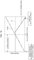
- the horizontal axis in FIG. 3 indicates the stroke of the valve element 21, and the vertical axis indicates the opening area.
- the stroke Ls in FIG. 3 corresponds to the discharging of the liquefied refrigerant shown in FIG. 2(a) , a state when the second valve portion 21B is fully closed (and the first valve portion 21C is fully open).
- the stroke Le indicates the state in FIG. 2(c) , when the second valve portion 21B is fully open (and the first valve portion 21C is fully closed).
- 3 is the stroke range that indicates the control region. Note also that the horizontal broken line located approximately at the midpoint of the vertical axis indicates a smallest opening area S1 among areas of the first valve portion 21C, the auxiliary communication passages 21E, and the intermediate communication passage 26 in the Pc-Ps flow path.
- an opening area S2 of the throttle valve portion 12 is set to be less than the area S1 in the control region, creating a bottleneck in the Pc-Ps flow path.
- the minimum opening area of the Pc-Ps flow path in the control region is set by the throttle valve portion 12, a simple component made up of the communication holes 23, which are provided between the second valve portion 21B and the third valve portion 21A, and the second valve hole 12A, which is provided between the second communication passages 8 and the third communication passages 9.
- the opening area S2 of the throttle valve portion 12 in the control region is indicated by a solid line.
- the throttle valve portion 12 is in a state where it produces the maximum opening area S2max, and the maximum opening area S2max is set to be the same or nearly the same as the area S1 of the auxiliary communication passages 21E (refer to FIG. 2(a) ).
- the control chamber pressure and the suction chamber pressure decrease, such that the pressure-sensitive element 22 extends and the third valve portion 21A closes.
- the solenoid portion 30 is controlled such that the second valve portion 21B starts moving from a fully closed state to a fully open state, and the throttle valve portion 12 starts moving from a fully open state toward a closed state. This narrows down the throttle valve portion 12, which is a bottleneck, so the Pc-Ps flow path is narrowed at the same time that the second valve portion face 21B1 of the second valve portion 21B separates from the second valve seat face 6A.
- the amount of the narrowing of the throttle valve portion 12 in relation to the stroke of the valve element 21 is set such that it is large when the second valve portion face 21B1 of the second valve portion 21B first separates from the second valve seat face 6A and the second valve portion 21B initially opens (between Ls and Lu in FIG. 3 ), and then becomes less after the initial opening of the valve (between Lu and Le in FIG. 3 ). It is therefore possible to narrow the Pc-Ps flow path rapidly. Because the amount of the refrigerant that flows through the Pc-Ps flow path during control of the variable capacity compressor can thus be decreased rapidly, it is possible to prevent a decrease in the efficiency of the variable capacity compressor.
- the amount of the narrowing of the throttle valve portion 12 in relation to the stroke of the valve element 21 is the narrowing rate of the throttle valve portion 12, and it is indicated by the slope of the opening area S2 line in FIG. 3 .
- the narrowing rate of the throttle valve portion 12 is set such that it is large when the second valve portion face 21B1 of the second valve portion 21B first separates from the second valve seat face 6A and the second valve portion 21B initially opens (between Ls and Lu in FIG. 3 ), and then becomes less after the initial opening of the valve (between Lu and Le in FIG. 3 ).
- the opening of the second valve portion 21B changes from 0% to 30%, and the opening of the throttle valve portion 12 is rapidly narrowed from 100% to around 10% to 30%.
- the opening of the second valve portion 21B changes from 30% to 100%, and the opening of the throttle valve portion 12 is gradually narrowed from around 10% to 30% down to a fully closed state of 0%.
- the opening area S2 of the throttle valve portion 12 in relation to the stroke of the valve element 21 varies according to the relative positions of the communication holes 23 and the second valve hole 12A, and can be varied in a non-linear manner according to the shape of the communication holes 23, as shown in FIG. 3 .
- the shape of the communication holes 23 in a front view is substantially circular, while the cross-sectional shape is a stepped shape (refer to FIG. 2(c) ) composed of a large diameter portion 23a on the side facing the second valve hole 12A and a small diameter portion 23b on the side facing the intermediate communication passage 26.
- the large diameter portion 23a is closed at one end and has a specified depth.
- the small diameter portion 23b is formed with a smaller diameter than the large diameter portion 23a and extends through the valve element 21.
- the large diameter portion 23a overlaps almost entirely with the second valve hole 12A, and the gap between the two decreases rapidly. Thereafter, a gap remains between the communication hole 23 and the second valve hole 12A in the radial direction, so the opening area changes as indicated by the solid line in FIG. 3 .
- the shape of the communication hole 23 in a front view is not limited to being substantially circular.
- the communication hole 23 may have a horizontal opening portion provided on the side of the second valve portion 21B, extending in a direction orthogonal to the valve axis, and an axial direction opening portion provided on the side of the third valve portion 21A, extending in the axial direction, with the horizontal opening portion being located above the axial direction opening portion to form a substantially T-shaped opening portion.
- the horizontal opening portion of the communication hole 23 overlaps with the second valve hole 12A, and the horizontal opening portion is narrowed rapidly.
- the axial direction opening portion of the communication hole 23 overlaps with the second valve hole 12A, and the axial direction opening portion is narrowed gradually, thereby making it possible to change the opening area as indicated by the solid line in FIG. 3 .
- the shape of the communication hole 23 may also be an inverted triangular shape, with the apex disposed on the side of the third valve portion 21A and the base disposed on the side of the second valve portion 21B in a front view.
- the communication holes 23 of the throttle valve portion 12 are closed off by the second valve hole 12A, starting from the base side of the triangle, thereby making it possible to change the opening area as indicated by the solid line in FIG. 3 .
- the shape of the communication hole 23 may thus be a circle, an ellipse, an inverted triangle, a trapezoid, a pentagon, or the like.
- the essential point is that the shape be such that the greater part of the opening area is closed off in the region where the valve element 21 initially moves after the liquefied refrigerant has been discharged, and that the lesser part of the opening area is thereafter closed off gradually. That makes it possible to change the opening area of the throttle valve portion 12 in relation to the stroke of the valve element 21 in a non-linear manner.
- the variable capacity compressor When the variable capacity compressor operates to discharge the liquefied refrigerant, the liquefied refrigerant is discharged to the suction chamber from the third valve portion 21A and the communication holes 23, both of which communicate with the intermediate communication passage 26, making it possible for the liquefied refrigerant to be discharged in a short period of time.
- the third valve portion 21A closes, and the second valve portion 21B starts to open, shifting the variable capacity compressor to control operation.
- the throttle valve portion 12 is significantly narrowed, so the flow of refrigerant gas from the control chamber to the suction chamber can be decreased rapidly, making it possible to improve the operating efficiency of the variable capacity compressor throughout the entire control region.
- the opening area S2 of the throttle valve portion 12 is set to be smaller than the area S1 of the auxiliary communication passages 21E.
- a capacity control valve according to a second embodiment of the present invention will be explained with reference to FIG. 4 .
- the capacity control valve 50 according to the second embodiment mainly differs from the capacity control valve 1 of the first embodiment in that a first valve body 52A is provided with an induction hole 53, but the basic configuration is otherwise the same as that in the first embodiment.
- the same reference numerals will be used for the same members, and redundant explanations will be omitted.
- a valve body 52 is composed of the first valve body 52A and the second valve body 2B, which is integrally fitted to one end of the first valve body 52A.
- the configuration of the second valve body 2B is the same as in the first embodiment.
- the first valve body 52A is newly provided with the induction hole 53, extending from the third valve chamber 4 to a solenoid portion 200 in parallel to the through-hole that defines the third valve chamber 4, the second valve chamber 6, and the first valve chamber 7.
- An induction channel 201A is also formed in a stator core 201 of the solenoid portion 200, in a position that faces the induction hole 53.
- a gap portion 36 is formed between the stator core 201 and the solenoid rod 25, and a clearance seal portion 207 having a narrower gap than the gap portion 36 is formed in the gap portion 36 between the stator core 201 and the solenoid rod 25.
- Equation 1 (- (Pc - Ps) ⁇ (S A - S B )) and the third term on the left side of Equation 2 (- (Pc - Ps) ⁇ S A ) describe the force acting in the direction in which the second valve portion 21B is closed.
- the pressure-receiving area S A in Equation 2 is greater than the area (S A - S B ) in Equation 1. That is, in the capacity control valve 50 in FIG. 4 , in which the pressure-receiving area (S A - S B ) is smaller, the force acting in the direction of closing the second valve portion 21B is smaller in relation to the same differential pressure (Pc - Ps) than it is in the capacity control valve 1 in FIG. 1 , in which the pressure-receiving area S A is larger, so the second valve portion 21B is more difficult to close. Accordingly, because the second valve portion 21B in the capacity control valve 50 in FIG.
- the increase in the variability of the control chamber pressure Pc in relation to the same differential pressure (Pc - Ps) occurs as herein described.
- the differential pressure (Pc - Ps) changes.
- the control chamber pressure Pc then changes immediately in accordance with the change in the differential pressure (Pc - Ps), such that the suction chamber pressure Ps quickly reverts to the set suction chamber pressure Pset.
- the capacity control valve 50 according to the second embodiment of the present invention achieves the significant effects hereinafter described.
- the fluid under the suction chamber pressure Ps can be introduced into the rear side of the plunger case 34 from the third valve chamber 4, making it possible not only to improve the responsiveness of the control chamber pressure Pc in relation to the suction chamber pressure Ps, but also to improve the responsiveness of the variable capacity compressor to the thermal load.
- the dimensions of pressure-sensitive elements, valve elements, and the like which have conventionally been designed individually in accordance with the properties of a specific variable capacity compressor, can now be matched to individual variable capacity compressors without making major design changes.
- a capacity control valve 60 according to a third embodiment of the present invention will be explained with reference to FIG. 5 .
- the capacity control valve 60 according to the third embodiment mainly differs from the capacity control valve 50 of the second embodiment in that the fluid under the suction chamber pressure Ps that is introduced into the rear side of the plunger case 34 from the third valve chamber 4 is sealed by a clearance seal portion 208 between a stator core 202 and the valve element 21, but the basic configuration is otherwise the same as that in the second embodiment.
- the same reference numerals will be used for the same members, and redundant explanations will be omitted.
- the first valve body 52A is the same as in the second embodiment in that the induction hole 53 is provided extending from the third valve chamber 4 to the solenoid portion 210 in parallel to the through-hole that defines the third valve chamber 4, the second valve chamber 6, and the first valve chamber 7, and that an induction channel 202A is formed in the stator core 202 of a solenoid portion 210, in a position that faces the induction hole 53. Furthermore, the clearance seal portion 208 is formed between the stator core 202 and the valve element 21, and the gap of the clearance seal portion 208 is narrower than the gap portion 36 between the stator core 202 and the solenoid rod 25.
- the fluid under the suction chamber pressure Ps in the third valve chamber 4 flows through the induction hole 53 and the induction channel 201A into the gap between the stator core 202 and the plunger case 34, then flows into the gap portion 36 between the stator core 202 and the solenoid rod 25 and is sealed at the clearance seal portion 208.
- the induction hole 53 is also provided in the first valve body 52A in the capacity control valve 60 of the third embodiment, the fluid under the suction chamber pressure Ps is introduced into the rear side of the plunger case 34 from the third valve chamber 4, but an pressure-receiving area S C of the clearance seal portion 208 is larger than the pressure-receiving area S B of the clearance seal portion 207 ( FIG. 4 ) of the capacity control valve 50 ( FIG. 4 ) of the second embodiment.
- Equation 3 (- (Pc - Ps) ⁇ (S A - S C )) according to the capacity control valve 60 of the third embodiment ( FIG. 5 ) describes the force acting in the direction in which the second valve portion 21B is closed.
- the pressure-receiving area Sc of the clearance seal portion 208 ( FIG. 5 ) is set to be greater than the pressure-receiving area S B of the clearance seal portion 207 ( FIG. 4 ), so the force (- (Pc - Ps) ⁇ (S A - S C )) acting in the direction in which the second valve portion 21B is closed becomes smaller in the capacity control valve 60 of the present embodiment ( FIG. 5 ).
- the second valve portion 21B in the capacity control valve 60 is more difficult to close in relation to the same differential pressure (Pc - Ps)
- the amount of the fluid supplied under the discharge chamber pressure Pd from the second valve chamber 6 through the first valve chamber 7 to the control chamber of the variable capacity compressor increases, and the control chamber pressure Pc is more variable.
- making the pressure-receiving area Sc of the clearance seal portion 208, which is subject to the suction chamber pressure Ps, larger than the pressure-receiving area S B of the clearance seal portion 207 of the capacity control valve 50 makes it possible to improve even further the responsiveness of the control chamber pressure Pc to changes in the suction chamber pressure Ps.
- FIG. 6 is a figure showing changes in the control chamber pressure Pc in relation to the suction chamber pressure Ps in the capacity control valve 1 of the first embodiment (configuration in FIG. 1 ), the capacity control valve 50 of the second embodiment (configuration in FIG. 4 ), and the capacity control valve 60 of the third embodiment (configuration in FIG. 5 ).
- the amount of change in the control chamber pressure Pc (the control output value) in relation to that in the suction chamber pressure Ps (the control input value) is smallest in the capacity control valve 1 of the configuration in FIG. 1 , then becomes successively greater in the capacity control valve 50 of the configuration in FIG. 4 and the capacity control valve 60 of the configuration in FIG. 5 .
- Adjusting the slope of the graph of the control chamber pressure Pc in relation to the suction chamber pressure Ps makes it possible to adjust the change in the control chamber pressure Pc in relation to the change in the suction chamber pressure Ps, so the capacity control valve can be easily matched to the properties of individual variable capacity compressors.
- the fluid under the suction chamber pressure Ps can be introduced into the rear side of the plunger case 34 from the third valve chamber 4, making it possible to adjust the responsiveness of the control chamber pressure Pc in relation to the change in the suction chamber pressure Ps by adjusting the pressure-receiving area of the clearance seal portion on which the suction chamber pressure Ps acts.
- the dimensions of bellows, valve elements, and the like, which have conventionally been designed individually in accordance with the properties of individual variable capacity compressors, can now be matched to the properties of individual variable capacity compressors without making major design changes.
- the responsiveness of the control chamber pressure Pc in relation to the change in the suction chamber pressure Ps can be improved, so even if the suction chamber pressure Ps of the variable capacity compressor deviates from the set suction chamber pressure Pset, the control chamber pressure Pc changes immediately in accordance with the change in the differential pressure (Pc - Ps), such that the suction chamber pressure Ps quickly reverts to the set suction chamber pressure Pset.
- a capacity control valve 70 according to a fourth embodiment of the present invention will be explained with reference to FIG. 7 .
- the capacity control valve 70 according to the fourth embodiment mainly differs from the capacity control valve 60 of the third embodiment in that the fluid under the discharge chamber pressure Pd is introduced into the first valve chamber 7 of the first valve body 52A, and the fluid under the control chamber pressure Pc is introduced into the second valve chamber 6.
- the same reference numerals will be used for members that are the same as in the capacity control valve 60, and redundant explanations will be omitted.
- the first valve body 52A includes the first valve chamber 7, the second valve chamber 6, and the third valve chamber 4, the first valve chamber 7 communicating with the first communication passages 10, through which the fluid under the discharge chamber pressure Pd passes, and having the second valve seat face 6A, the second valve chamber 6 having the first valve hole 5, which communicates with the first valve chamber 7, and communicating with the second communication passages 8, through which the fluid under the control chamber pressure Pc passes, and the third valve chamber 4 communicating with the third communication passages 9, through which the fluid under the suction chamber pressure Ps passes.
- a valve element 71 includes a second valve portion 71B, an intermediate communication passage 76, and a third valve portion 71A, the second valve portion 71B separating from and coming into contact with the second valve seat face 6A in order to open and close the first valve hole 5, through which the first valve chamber 7 and the second valve chamber 6 communicate with one another, the intermediate communication passage 76 allowing the second valve chamber 6 and the third valve chamber 4 to communicate with one another through auxiliary communication passages 71E and communication holes 73, and the third valve portion 71A opening and closing the third valve chamber 4 and the intermediate communication passage 76 by separating from and coming into contact with the third valve seat face 22C of the pressure-sensitive element 22.
- the valve element 71 does not include a first valve portion disposed in the first valve chamber 7 and performing opening and closing operations in the opposite direction from the second valve portion 71B.
- a throttle valve portion 72 is provided that includes the communication holes 73 and a second valve hole 72A, the communication holes 73 allowing the third valve chamber 4 and the intermediate communication passage 76 to communicate with one another between the third valve portion 71A and the second valve portion, and the second valve hole 72A being provided between the second valve chamber 6 and the third valve chamber 4.
- the amount of the narrowing of the throttle valve portion 72 is large when a second valve portion face 71B1 of the second valve portion 71B starts to separate from the second valve seat face 6A and the valve initially opens, and then becomes less after the initial opening of the valve.
- the capacity control valve 70 according to the fourth embodiment of the present invention achieves the significant effects hereinafter described.
- the variable capacity compressor When the variable capacity compressor operates to discharge the liquefied refrigerant, the liquefied refrigerant is discharged to the suction chamber from the third valve portion 71A and the communication holes 73, both of which communicate with the intermediate communication passage 76, making it possible for the liquefied refrigerant to be discharged in a short period of time.
- the third valve portion 71A closes, and the second valve portion 71B starts to open, shifting the variable capacity compressor to control operation.
- the throttle valve portion 72 is significantly narrowed, so the flow of refrigerant gas from the control chamber to the suction chamber can be decreased rapidly, making it possible to improve the operating efficiency of the variable capacity compressor throughout the entire control region.
- the fluid under the suction chamber pressure Ps can be introduced into the rear side of the plunger case 34 from the third valve chamber 4, making it possible to adjust the responsiveness of the control chamber pressure Pc in relation to the change in the suction chamber pressure Ps by adjusting the pressure-receiving area of the clearance seal portion on which the suction chamber pressure Ps acts.
- the dimensions of bellows, valve elements, and the like, which have conventionally been designed individually in accordance with the properties of individual variable capacity compressors, can now be matched to the properties of individual variable capacity compressors without making major design changes.
Landscapes
- Engineering & Computer Science (AREA)
- General Engineering & Computer Science (AREA)
- Mechanical Engineering (AREA)
- Magnetically Actuated Valves (AREA)
- Compressors, Vaccum Pumps And Other Relevant Systems (AREA)
- Multiple-Way Valves (AREA)
Abstract
Description
- The present invention relates to a capacity control valve for variably controlling the capacity or pressure of a working fluid, and particularly relates to a capacity control valve for controlling, in accordance with a pressure load, the discharge rate of a variable capacity compressor or the like suitable for an air conditioning system of an automobile or the like.
- A swash plate type variable capacity compressor suitable for an air-conditioning system of an automobile or the like includes a rotating shaft rotationally driven by a rotational force of an engine, a swash plate coupled to the rotating shaft such that the plate's angle of inclination can be varied, a piston for compression coupled to the swash plate, and the like. By varying the angle of inclination of the swash plate to vary the stroke of the piston, the compressor controls the discharge rate of a refrigerant gas.
- The angle of inclination of the swash plate can be continuously varied by appropriately controlling the pressure inside the control chamber using a capacity control valve that is opened and closed by electromagnetic force, and thereby regulating the balance of pressures acting on opposite faces of the piston, while utilizing a suction pressure of a suction chamber for drawing in the refrigerant, a discharge pressure of a discharge chamber for discharging the refrigerant pressurized by the piston, and a control chamber pressure of a control chamber (a crank chamber) in which the swash plate is housed.
- As an example of this type of capacity control valve, as shown in
FIG. 8 , a valve is known that includes asecond communication passage 173 and avalve hole 177 providing communication between a discharge chamber and a control chamber; asecond valve chamber 182 formed in the middle of a discharge-side passage; athird communication passage 171 and aflow channel 172 providing communication between a suction chamber and the control chamber; athird valve chamber 183 formed in the middle of a suction-side passage; avalve element 181 formed such that asecond valve portion 176, disposed in thesecond valve chamber 182 and opening and closing thesecond communication passage 173 and thevalve hole 177, and athird valve portion 175, disposed in thethird valve chamber 183 and opening and closing thethird communication passage 171 and theflow channel 172, move in reciprocating motion as a single unit, with one of thesecond valve portion 176 and thethird valve portion 175 performing its opening operation at the same time that the other performs its closing operation; afirst valve chamber 184 formed near the control chamber; a pressure-sensitive element (a bellows) 178 disposed in the first valve chamber, exerting a biasing force in a direction of extension (expansion) and contracting in accordance with an increase in pressure in its environment; a valve seat body (an engaging portion) 180 provided on a free end of the pressure-sensitive element in the extension and contraction direction and having an annular seat face; a first valve portion (a valve opening coupling portion) 179 moving in thefirst valve chamber 184 as a single unit with thevalve element 181 and capable of opening and closing the suction-side passage by engaging with and disengaging from thevalve seat body 180; a solenoid S exerting an electromagnetic driving force on thevalve element 181; and the like. (Hereinafter referred to as "conventional art". For example, seePatent Citation 1.) - Further, even though a clutch mechanism is not provided in the variable capacity compressor, in a case where it becomes necessary to vary the control chamber pressure Pc while capacity control is in progress, a
capacity control valve 170 is able to adjust the pressure inside the control chamber (the control chamber pressure) by making the discharge chamber and the control chamber communicate with one another. Thecapacity control valve 170 is also configured such that, in a case where the control chamber pressure Pc has increased while the variable capacity compressor is in a stopped state, the first valve portion (the valve opening coupling portion) 179 disengages from the valve seat body (the engaging portion) 180, thereby opening the suction-side passage and making the suction chamber and the control chamber communicate with one another. - Note that in a case where the swash plate type variable capacity compressor is stopped and left inoperative for a long period of time, liquefied refrigerant (refrigerant gas that has been liquefied by cooling while the compressor is inoperative) accumulates in the control chamber (the crank chamber). As long as the liquefied refrigerant is not discharged, the refrigerant gas cannot be compressed when the compressor is restarted, and the pre-set discharge rate cannot be ensured. In order for the desired capacity control to be performed immediately after the compressor is restarted, it is necessary for the liquefied refrigerant to be discharged from the control chamber (the crank chamber) as quickly as possible.
- Therefore, the conventional art described above is configured such that an
auxiliary communication passage 179 is provided in the valve seat body (the engaging portion) 180, thereby making communication possible from thefirst valve chamber 184, through theauxiliary communication passage 185, anintermediate communication passage 186, and theflow channel 172, to thethird communication passage 171, which is in a state of being at the suction chamber pressure. Thus, when the variable capacity compressor is started for cooling, the liquefied refrigerant is discharged from the control chamber (the crank chamber) to the suction chamber, as shown by the arrow inFIG. 8 , thereby vaporizing the refrigerant liquid in the control chamber. This enables the compressor to be brought into a cooling operation in from one-fifteenth to one-tenth the time required by a capacity control valve in which theauxiliary communication passage 185 is not provided. -
FIG. 8 shows a state in which electric current is supplied to the solenoid S, release spring means 187 has contracted, and thethird valve portion 175 has opened. In contrast, when electric current is not supplied to the solenoid S, the release spring means 187 extends, such that thethird valve portion 175 closes, thesecond valve portion 176 is brought into an open state, and thefirst valve portion 179 opens under the suction chamber pressure Ps and the control chamber pressure Pc. - Further, when the compressor starts, the refrigerant liquid in the control chamber vaporizes, and fluid under the control chamber pressure Pc flows from a
first communication passage 174 to thefirst valve chamber 184. In this state, the suction chamber pressure Ps and the control chamber pressure Pc are high, such that the pressure-sensitive element (the bellows) 178 contracts and a gap opens between thefirst valve portion 179 and thevalve seat body 180. However, the size of the opening between thefirst valve portion 179 and thevalve seat body 180 is functionally restricted, so the vaporization of the refrigerant liquid in thefirst valve chamber 184 is accelerated only slightly by the opening of the valve. Accordingly, the refrigerant liquid in the control chamber can be made to vaporize much faster by providing theauxiliary communication passage 185, which communicates with theintermediate communication passage 186. - However, a problem exists with the conventional art described above. For example, when the liquefied refrigerant has been completely discharged from the control chamber (the crank chamber) and the variable capacity compressor has shifted to controlling operation, even if the gap between the
first valve portion 179 and the valve seat face of the valve seat body 18 is in a closed state, and theauxiliary communication passage 185 communicating with theintermediate communication passage 186, remains open, so the refrigerant gas flows from the control chamber to the suction chamber through theauxiliary communication passage 185 and theintermediate communication passage 186. This leads to a decrease in the operating efficiency of the variable capacity compressor. - This point will be explained in detail with reference to
FIGS. 8 to 10 . InFIGS. 8 to 10 , where S1 is the (constant) area of theauxiliary communication passage 185, S2 is the maximum opening area of thethird valve portion 175, L is the maximum stroke of the valve element 181 (the stroke from completely closed to completely open), and Lm is the stroke of thevalve element 181 in a control region, the values are set in the conventional art are as follows: S2 ≥ S1 - Accordingly, as shown by the solid line in
FIG. 10 , the refrigerant gas, which is determined by the area S1 of theauxiliary communication passage 185, flows from the control chamber to the suction chamber in the entire control region, and the flow of the refrigerant gas is not restricted until thevalve element 181 passes the position of the stroke Lm in the control region and approaches the maximum stroke L. Therefore, a decrease in the operating efficiency of the variable capacity compressor is unavoidable while the control is being performed. - Patent Document 1:
JP 5167121 B - In order to address the problem with the conventional art described above, the present invention provides a capacity control valve having an auxiliary communication passage to be improved in the function for discharging a liquefied refrigerant from a control chamber when a variable capacity compressor is started, the capacity control valve also shortening the start-up time for the variable capacity compressor and improving both the operating efficiency and the control responsiveness when control is being performed.
- In order to address the problem described above, a capacity control valve of the present invention is a capacity control valve controlling, in accordance with a degree of opening of a valve portion, a flow rate or a pressure inside an operation control chamber.
- The capacity control valve includes a valve body, a pressure-sensitive element, a valve element, a solenoid portion, and a throttle valve portion.
- The valve body has a first valve chamber, a second valve chamber, and a third valve chamber, the first valve chamber communicating with a first communication passage, through which a fluid under a control chamber pressure passes, and having a first valve seat face and a second valve seat face, the second valve chamber having a first valve hole, which communicates with the first communication passage, and communicating with a second communication passage, through which a fluid under a discharge chamber pressure passes, and the third valve chamber communicate with a third communication passage, through which a fluid under a suction chamber pressure passes.
- The pressure-sensitive element is disposed in the third valve chamber, extending and contracting in reaction to the suction chamber pressure and having a third valve seat face disposed on an extending and contracting free end.
- The valve element has an intermediate communication passage, a second valve portion, a first valve portion, and a third valve portion, the intermediate communication passage allowing the first valve chamber and the third valve chamber to communicate with one another through an auxiliary communication passage, the second valve portion opening and closing the first valve hole by separating from and coming into contact with the second valve seat face, the first valve hole allowing the first valve chamber and the second valve chamber to communicate with one another, the first valve portion opening and closing the auxiliary communication passage by moving in conjunction with and in the opposite direction from the second valve portion, and the third valve portion opening and closing the intermediate communication passage and the third valve chamber by separating from and coming into contact with the third valve seat face.
- The solenoid portion is attached to the valve body and has an electromagnetic coil portion, a plunger, a stator core, and a rod connecting the plunger to the valve element, the solenoid portion operating to open and close the individual valve portions of the valve element in accordance with an electric current flowing through the electromagnetic coil portion.
- The throttle valve portion has a communication hole, disposed between the second valve portion and the third valve portion and allowing the intermediate communication passage and the third valve chamber to communicate with one another, and a second valve hole, disposed between the second valve chamber and the third valve chamber.
- An amount of narrowing of the throttle valve portion in relation to a stroke of the valve element is large during an initial valve opening, when the second valve portion separates from the second valve seat face, and becomes smaller after the initial valve opening.
- According to this aspect, when the variable capacity compressor operates to discharge the liquefied refrigerant, the liquefied refrigerant is discharged to the suction chamber through the third valve portion and the communication hole, both of which communicate with the intermediate communication passage, making it possible for the liquefied refrigerant to be discharged in a short period of time. When the discharging of the liquefied refrigerant has been completed, the control chamber pressure and the suction chamber pressure decrease, the third valve portion closes, and the second valve portion starts to open, shifting the variable capacity compressor to control operation. At this time, the throttle valve portion significantly narrows the communication hole, so the flow of a refrigerant gas through the communication hole from the control chamber to the suction chamber is greatly throttled, making it possible to prevent a deterioration in the operating efficiency of the variable capacity compressor.
- In the capacity control valve of the present invention, the valve body is provided with an induction hole making the third valve chamber and the solenoid portion communicate with one another to regulate the sensitivity of the control chamber pressure to changes in the suction chamber pressure.
- According to this aspect, even if the suction chamber pressure of the variable capacity compressor deviates from a set pressure, the suction chamber pressure can be made to revert quickly to the set pressure.
- In the capacity control valve of the present invention, a gap portion between the rod and the stator core of the solenoid portion is provided with a clearance seal portion regulating the sensitivity of the control chamber pressure to changes in the suction chamber pressure.
- According to this aspect, the sensitivity of the control chamber pressure to changes in the suction chamber pressure can be adjusted by regulating the clearance seal portion, making it possible to match the capacity control valve to the properties of the variable capacity compressor.
- In the capacity control valve of the present invention, a gap portion between the valve element and the stator core of the solenoid portion is provided with a clearance seal portion regulating the sensitivity of the control chamber pressure to changes in the suction chamber pressure.
- According to this aspect, the sensitivity of the control chamber pressure to changes in the suction chamber pressure can be adjusted by regulating the clearance seal portion, making it possible to match the capacity control valve to the properties of the variable capacity compressor.
- A capacity control valve of the present invention is a capacity control valve controlling, in accordance with a degree of opening of a valve portion, one of a flow rate and a pressure inside an operation control chamber.
- The capacity control valve includes a valve body, a pressure-sensitive element, a valve element, a solenoid portion, and a throttle valve portion.
- The valve body has a first valve chamber, a second valve chamber, and a third valve chamber, the first valve chamber communicating with a first communication passage, through which a fluid under a discharge chamber pressure passes, and having a second valve seat face, the second valve chamber having a first valve hole, which communicates with the first communication passage, and communicating with a second communication passage, through which a fluid under a control chamber pressure passes, and the third valve chamber communicating with a third communication passage, through which a fluid under a suction chamber pressure passes.
- The pressure-sensitive element is disposed in the third valve chamber, extending and contracting in reaction to the suction chamber pressure and having a third valve seat face disposed on an extending and contracting free end.
- The valve element has a second valve portion, an intermediate communication passage, and a third valve portion, the second valve portion opening and closing the first valve hole by separating from and coming into contact with the second valve seat face, the first valve hole allowing the first valve chamber and the second valve chamber to communicate with one another, the intermediate communication passage allowing the second valve chamber and the third valve chamber to communicate with one another through an auxiliary communication passage, and the third valve portion opening and closing the third valve seat face, which allows the intermediate communication passage and the third valve chamber to communicate with one another.
- The solenoid portion is attached to the valve body and has an electromagnetic coil portion, a plunger, a stator core, and a rod connecting the plunger to the valve element, the solenoid portion operating to open and close the individual valve portions of the valve element in accordance with an electric current flowing through the electromagnetic coil portion.
- The throttle valve portion has a communication hole, disposed between the second valve portion and the third valve portion and allowing the intermediate communication passage and the third valve chamber to communicate with one another, and a second valve hole, disposed between the second valve chamber and the third valve chamber.
- An amount of narrowing of the throttle valve portion in relation to a stroke of the valve element is large during an initial valve opening, when the second valve portion separates from the second valve seat face, and becomes smaller after the initial valve opening.
- According to this aspect, when the variable capacity compressor operates to discharge the liquefied refrigerant, the liquefied refrigerant is discharged to the suction chamber through the third valve portion and the communication hole, both of which communicate with the intermediate communication passage, making it possible for the liquefied refrigerant to be discharged in a short period of time. When the discharging of the liquefied refrigerant has been completed, the control chamber pressure and the suction chamber pressure decrease, the third valve portion closes, and the second valve portion starts to open, shifting the variable capacity compressor to control operation. At this time, the throttle valve portion significantly narrows the communication hole, so a refrigerant gas through the communication hole from the control chamber to the suction chamber is greatly throttled, making it possible to prevent a deterioration in the operating efficiency of the variable capacity compressor.
- In the capacity control valve of the present invention, the valve body is provided with an induction hole making the third valve chamber and the solenoid portion communicate with one another to regulate the sensitivity of the control chamber pressure to changes in the suction chamber pressure.
- According to this aspect, the suction chamber pressure of the variable capacity compressor can be made to revert quickly to a set suction chamber pressure.
- In the capacity control valve of the present invention, a gap portion between the rod and the stator core of the solenoid portion is provided with a clearance seal portion regulating the sensitivity of the control chamber pressure to changes in the suction chamber pressure.
- According to this aspect, the sensitivity of the control chamber pressure to changes in the suction chamber pressure can be adjusted by regulating the clearance seal portion, making it possible to match the capacity control valve to the properties of the variable capacity compressor.
- In the capacity control valve of the present invention, a gap portion between the valve element and the stator core of the solenoid portion is provided with a clearance seal portion regulating the sensitivity of the control chamber pressure to changes in the suction chamber pressure.
- According to this aspect, the sensitivity of the control chamber pressure to changes in the suction chamber pressure can be adjusted by regulating the clearance seal portion, making it possible to match the capacity control valve to the properties of the variable capacity compressor.
-
-
FIG. 1 is a front section view showing a capacity control valve according to a first embodiment of the present invention. -
FIG. 2 is an enlarged view of a Pc-Ps flow path inFIG. 1 , showing open and closed states of valve portions of a valve element in various circumstances. -
FIG. 3 is a figure showing relationships between a stroke of the valve element and opening areas of the Pc-Ps flow path and a Pd-Pc flow path of the capacity control valve according to the first embodiment. -
FIG. 4 is a front section view showing a capacity control valve according to a second embodiment of the present invention. -
FIG. 5 is a front section view showing a capacity control valve according to a third embodiment of the present invention. -
FIG. 6 is a figure showing changes in a control chamber pressure Pc in relation to a suction chamber pressure Ps in thecapacity control valve 1 of the first embodiment, thecapacity control valve 50 of the second embodiment, and thecapacity control valve 60 of the third embodiment. -
FIG. 7 is a front section view showing a capacity control valve according to a fourth embodiment of the present invention. -
FIG. 8 is a front section view showing a capacity control valve of a conventional art. -
FIG. 9 is an enlarged view of a Pc-Ps flow path in the capacity control valve according to the conventional art, showing open and closed states of a valve portion of a valve element in various circumstances. -
FIG. 10 is a figure showing relationships between a stroke of the valve element and opening areas of the Pc-Ps flow path and a Pd-Pc flow path of the capacity control valve according to the conventional art. - Hereinafter, forms of the present invention will be explained with reference to the drawings, as exemplified by embodiments. However, the dimensions, materials, shapes, relative positions, and the like of the components described in the embodiments are not intended to serve as limits on the present invention unless otherwise explicitly described.
- A capacity control valve according to a first embodiment of the present invention will be explained with reference to
FIGS. 1 to 3 . InFIG. 1 , thereference numeral 1 refers to the capacity control valve. Thecapacity control valve 1 mainly includes avalve body 2, avalve element 21, a pressure-sensitive element 22, and asolenoid portion 30. Hereinafter, the components of thecapacity control valve 1 will be explained individually. - The
valve body 2 includes afirst valve body 2A and asecond valve body 2B, thefirst valve body 2A having a functioning through-hole in its interior and thesecond valve body 2B integrally fitted to one end of thefirst valve body 2A. Thefirst valve body 2A may be composed of a metal such as brass, iron, aluminum, stainless steel, or the like, or from a synthetic resin or the like. Meanwhile, thesecond valve body 2B, because it functions as a magnetic path for thesolenoid portion 30, is composed of a magnetic material with low magnetic reluctance, such as iron or the like. Because it differs from thefirst valve body 2A in both its material and function, thesecond valve body 2B is provided as a separate component from thefirst valve body 2A. As long as this point is taken into consideration, the shape of thesecond valve body 2B shown inFIG. 1 may be modified as desired. - The
first valve body 2A is a hollow cylindrical member having a through-hole extending through it in the axial direction, with athird valve chamber 4, asecond valve chamber 6, and afirst valve chamber 7 being continuously provided in sections of the through-hole. Specifically, thethird valve chamber 4 is formed in a section at one end of the through-hole, thesecond valve chamber 6 is continuously provided adjacent to thethird valve chamber 4 on the side of thesolenoid portion 30 of thethird valve chamber 4, and thefirst valve chamber 7 is continuously provided adjacent to thesecond valve chamber 6 on the side of thesolenoid portion 30 of thesecond valve chamber 6. In addition, asecond valve hole 12A is continuously provided between thethird valve chamber 4 and thesecond valve chamber 6, its diameter being smaller than the diameters of the second and third valve chambers. Furthermore, afirst valve hole 5 is continuously provided between thesecond valve chamber 6 and thefirst valve chamber 7, its diameter being smaller than the diameters of the second and first valve chambers, and a secondvalve seat face 6A is provided around thefirst valve hole 5 on the side of thefirst valve chamber 7. -
Third communication passages 9 are connected to thethird valve chamber 4. Thethird communication passages 9 communicate with a suction chamber of a variable capacity compressor (not shown) and are configured such that thecapacity control valve 1 can cause a fluid under a suction chamber pressure Ps to flow into and out of thethird valve chamber 4. -
Second communication passages 8 are connected to thesecond valve chamber 6. Thesecond communication passages 8 communicate with a discharge chamber of the variable capacity compressor and are configured such that thecapacity control valve 1 can allow a volume of a fluid under a discharge chamber pressure Pd to flow into a control chamber. -
First communication passages 10 are formed in thefirst valve chamber 7. Thefirst communication passages 10 communicate with the control chamber (the crank chamber) of the variable capacity compressor and allow the fluid that has flowed in from thesecond valve chamber 6 under the discharge chamber pressure Pd to flow out to the control chamber (the crank chamber) of the variable capacity compressor, as will be described later. - Note that the
first communication passages 10, thesecond communication passages 8, and thethird communication passages 9 each extend through the periphery of thevalve body 2 at from two to six equally distributed points. Further, the outer periphery of thevalve body 2 is formed into four stepped sections, and mounting grooves for O-rings are provided in the outer periphery at three locations that are set apart from one another in the axial direction. An O-ring 46 is provided in each one of the mounting grooves to seal the gap between thevalve body 2 and mounting holes of a casing (not shown) that is fitted onto thevalve body 2, thereby providing a configuration in which the flow paths of thefirst communication passages 10, thesecond communication passages 8, and thethird communication passages 9 are mutually independent. - The pressure-
sensitive element 22 is provided inside thethird valve chamber 4. One end of a metal bellows 22A of the pressure-sensitive element 22 is tightly joined to apartition adjustment portion 3. Thebellows 22A may be made of phosphor bronze or the like, and it is designed to have a spring constant of s specified value. The space inside the pressure-sensitive element 22 may be one of a vacuum and a space filled with air. The pressure-sensitive element 22 is configured such that it contracts when a pressure inside the third valve chamber 4 (for example, a pressure Pc) and the suction chamber pressure Ps act on an effective pressure-receiving area SBL of thebellows 22A of the pressure-sensitive element 22. Avalve seat portion 22B is provided on the free end of the pressure-sensitive element 22, thevalve seat portion 22B being dish-shaped and having a third valve seat face 22C around the inner periphery of its end portion. - The
partition adjustment portion 3 of the pressure-sensitive element 22 is fitted such that it seals off thethird valve chamber 4 of thefirst valve body 2A. Note that the spring force of thebellows 22A or of a compression spring that is disposed inside and parallel to thebellows 22A can be adjusted in the axial direction by tightening a set screw (not shown). - Next, the
valve element 21 will be explained. Thevalve element 21 is a hollow cylindrical member having anintermediate communication passage 26 extending through it in the axial direction, with athird valve portion 21A, asecond valve portion 21B, and afirst valve portion 21C being continuously provided, and havingauxiliary communication passages 21E and communication holes 23 communicating with theintermediate communication passage 26. Thevalve element 21 is provided such that it moves freely in the axial direction within the through-hole of thefirst valve body 2A. - A third valve portion face 21A1 is provided on one end of the
valve element 21. By separating from and coming into contact with the thirdvalve seat face 22C of the pressure-sensitive element 22, the third valve portion face 21A1 opens and closes theintermediate communication passage 26 and thethird valve chamber 4. When the third valve portion face 21A1 and the thirdvalve seat face 22C change from a state of contact to a state of separation, thethird valve portion 21A opens, and when the third valve portion face 21A1 and the thirdvalve seat face 22C change from a state of separation to a state of contact, thethird valve portion 21A closes. - The
second valve portion 21B of thevalve element 21 is provided on the opposite side of thethird valve portion 21A from the third valve portion face 21A1. Thesecond valve portion 21B at an intermediate portion of thevalve element 21 is disposed in thesecond valve chamber 6. A second valve portion face 21B1 that comes into contact with the secondvalve seat face 6A is provided in thesecond valve portion 21B, and the outside diameter of thesecond valve portion 21B is formed to be smaller than the diameter of thefirst valve hole 5. When the second valve portion face 21B1 and the secondvalve seat face 6A change from a state of contact to a state of separation, thesecond valve portion 21B opens, such that thesecond valve chamber 6 communicates with thefirst valve chamber 7, enabling a fluid under the discharge chamber pressure Pd to flow. Conversely, when the second valve portion face 21B1 and the secondvalve seat face 6A change from a state of separation to a state of contact, thesecond valve portion 21B closes, such that thesecond valve chamber 6 and thefirst valve chamber 7 are cut off from one another and the flow of the fluid under the discharge chamber pressure Pd is closed off. Hereinafter, the flow path from thesecond communication passages 8, thesecond valve chamber 6, and thefirst valve hole 5, which communicate with the discharge chamber, through thesecond valve portion 21B, to thefirst valve chamber 7 and thefirst communication passages 10, which communicate with the control chamber, will be called the Pd-Pc flow path. That is, the Pd-Pc flow path from thesecond communication passages 8 to thefirst communication passages 10 is opened and closed off by the opening and closing of thesecond valve portion 21B. - A linking
portion 25A of thevalve element 21 provided on the lower end of asolenoid rod 25 is fitted into afitting portion 21D of thevalve element 21. Thefirst valve portion 21C is provided between thefitting portion 21D and thesecond valve portion 21B and is disposed inside thefirst valve chamber 7. Theauxiliary communication passages 21E are provided at four equally distributed positions, for example, inside thefirst valve chamber 7, directly below thefitting portion 21D. Thefirst valve chamber 7 communicates with theintermediate communication passage 26 through theauxiliary communication passages 21E. Note that thefirst valve chamber 7 is configured such that it has a face with a substantially larger diameter than the outside diameter of thefirst valve portion 21C, enabling fluid under a control chamber pressure Pc to flow readily into thefirst valve chamber 7 from thefirst communication passages 10. - A first
valve seat face 31A is formed on the lower end face of astator core 31 of thesolenoid portion 30. When thefirst valve portion 21C and the firstvalve seat face 31A change from a state of contact to a state of separation, thefirst valve portion 21C opens, such that the fluid under the control chamber pressure Pc flows out from thefirst communication passages 10 and thefirst valve chamber 7, through theauxiliary communication passages 21E, theintermediate communication passage 26, and athrottle valve portion 12, to thethird valve chamber 4 and thethird communication passages 9. Conversely, when thefirst valve portion 21C and the firstvalve seat face 31A change from a state of separation to a state of contact, thefirst valve portion 21C closes, such that the flow of the fluid under the control chamber pressure Pc from thefirst communication passages 10 and thefirst valve chamber 7, through theauxiliary communication passages 21E, theintermediate communication passage 26, and thethrottle valve portion 12, to thethird valve chamber 4 and thethird communication passages 9 is closed off. Hereinafter, the flow path from thefirst communication passages 10 and thefirst valve chamber 7, which communicate with the control chamber, through thefirst valve portion 21C, theauxiliary communication passages 21E, theintermediate communication passage 26, and thethrottle valve portion 12, to thethird valve chamber 4, which communicates with the suction chamber, will be called the Pc-Ps flow path. That is, the Pc-Ps flow path from thefirst communication passages 10 to thethird communication passages 9 is opened and closed off by the opening and closing of thefirst valve portion 21C. - At least one of the communication holes 23, which communicates with the
intermediate communication passage 26, is provided between thethird valve portion 21A and thesecond valve portion 21B, and the communication holes 23 function as thethrottle valve portion 12 by sliding in relation to thesecond valve hole 12A. The communication holes 23 of thethrottle valve portion 12, by moving in the axial direction in relation to thesecond valve hole 12A, move forward and backward within thethird valve chamber 4, such that the opening area of the communication holes 23 changes from a fully open state to a fully closed state in relation to thethird valve chamber 4. - Next, the
solenoid portion 30 will be explained. Thesolenoid portion 30 is configured such that thesolenoid rod 25, aplunger case 34, anelectromagnetic coil 35, thestator core 31, aplunger 32, and spring means 28 are contained in asolenoid case 33. Thestator core 31, to which thesecond valve body 2B is fixed, is provided between thevalve element 21 and theplunger 32. Thesolenoid rod 25 is fitted into a through-hole 31D of thestator core 31 such that it can move freely, with the linkingportion 25A of thesolenoid rod 25 being fitted into thefitting portion 21D of thevalve element 21, and the opposite end of thesolenoid rod 25 being fitted into afitting hole 32A of theplunger 32. - The
plunger case 34 is a hollow cylindrical member that is open at one end and closed at the other end. It is fitted into the inside diameter portion of theelectromagnetic coil 35, its open end being fitted into a fitting hole of thesecond valve body 2B such that it is tightly sealed, and its closed end being fixed in a fitting hole in an end portion of thesolenoid case 33.
Theelectromagnetic coil 35 is thus tightly sealed by theplunger case 34, thesecond valve body 2B, and thesolenoid case 33, and any decrease in its insulation resistance can be prevented, because it does not come into contact with the refrigerant. - The
stator core 31 and theplunger 32 are provided inside theplunger case 34, and theplunger 32 is fitted into theplunger case 34 such that it moves freely. Aspring seat chamber 31C is formed close to the end of thestator core 31 that faces theplunger 32. The spring means (hereinafter, also called the elastic means) 28, which changes thefirst valve portion 21C and thesecond valve portion 21B from a closed state to an open state, is disposed in thespring seat chamber 31C. Specifically, the spring means 28 acts so as to keep theplunger 32 apart from thestator core 31. Anadsorption face 31B tostator core 31 and a joiningface 32B of theplunger 32 are tapered faces that are opposite one another, and they are disposed such that a gap is provided between the opposing faces. - The separation and contact of the
adsorption face 31B of thestator core 31 and the joiningface 32B of theplunger 32 is performed in accordance with the strength of the electric current flowing through theelectromagnetic coil 35. Specifically, in a state in which current is not flowing through theelectromagnetic coil 35, the repelling force of the spring means 28 forms the maximum gap between theadsorption face 31B of thestator core 31 and the joiningface 32B of theplunger 32, such that thefirst valve portion 21C and thethrottle valve portion 12 close, and thesecond valve portion 21B opens. In contrast, in a state in which current is flowing through theelectromagnetic coil 35, the magnetic attractive force attracts the joiningface 32B of theplunger 32 to theadsorption face 31B of thestator core 31, such that thefirst valve portion 21C and thethrottle valve portion 12 open, and thesecond valve portion 21B closes. The magnitude of the electric current that is supplied to theelectromagnetic coil 35 is controlled by a control portion (not shown), in accordance with the open and closed states of the valve portions of thevalve element 21. - The operation of the
capacity control valve 1 having the configuration explained above will be explained. In a case where the variable capacity compressor is stopped and then restarted after being left inoperative for a long period of time, a state is created in which liquefied refrigerant (refrigerant gas that has been liquefied by cooling while the compressor is inoperative) has accumulated in the control chamber (the crank chamber). Therefore, the pressure in the control chamber cannot be freely controlled by thecapacity control valve 1, so the refrigerant gas cannot be reliably compressed, and the pre-set discharge rate cannot be ensured. Accordingly, in order to perform the desired capacity control immediately after the compressor is restarted, thecapacity control valve 1 of the present invention discharges the liquefied refrigerant from the control chamber (the crank chamber) as quickly as possible, such that the refrigerant is vaporized. - The operating states of the
first valve portion 21C, thesecond valve portion 21B, thethird valve portion 21A, and thethrottle valve portion 12 will be explained with reference toFIGS. 1 and2 . Note that inFIGS. 1 and2(a) , the solid line arrow from thefirst communication passages 10 to thethird communication passages 9 indicates the Pc-Ps flow path. - During the liquefied refrigerant discharge shown in
FIG. 2(a) (during maximum capacity control), that is, with thesecond valve portion 21B in a fully closed state, thefirst valve portion 21C in a fully open state, and thethrottle valve portion 12 in a fully open state, the fluid under the control chamber pressure Pc (the fluid under the control chamber pressure PC being the refrigerant liquid that has vaporized during the liquefied refrigerant discharge) flows into thethird valve chamber 4 through theauxiliary communication passages 21E, theintermediate communication passage 26, and the communication holes 23 of thethrottle valve portion 12, then flows out of thethird valve chamber 4 to thethird communication passages 9. - In the state in
FIG. 2(a) , the communication holes 23 of thethrottle valve portion 12 produce a maximum opening area S2max in relation to thesecond valve hole 12A. Here, the positions and shapes of the communication holes 23 are set such that the maximum opening area S2max is not greater than the minimum opening area among areas of thefirst valve portion 21C, theintermediate communication passage 26, and theauxiliary communication passages 21E (the total opening area where a plurality of the auxiliary communication passages are provided). That is, thethrottle valve portion 12 is a bottleneck in the Pc-Ps flow path. - Next, when the discharge of the liquefied refrigerant has been completed and operation shifts into a control region, as shown in
FIG. 2(b) , the control chamber pressure and the suction chamber pressure decrease, such that the pressure-sensitive element 22 extends and thethird valve portion 21A closes. Thesolenoid portion 30 is controlled such that thesecond valve portion 21B starts moving from a fully closed state to a fully open state, and thethrottle valve portion 12 starts moving from a fully open state toward a closed state. This narrows down thethrottle valve portion 12, which is a bottleneck, so the Pc-Ps flow path is narrowed at the same time that the second valve portion face 21B1 of thesecond valve portion 21B separates from the secondvalve seat face 6A. Furthermore, the amount of the narrowing of thethrottle valve portion 12 in relation to the stroke of thevalve element 21 is set such that it is large when the second valve portion face 21B1 of thesecond valve portion 21B first separates from the secondvalve seat face 6A and thesecond valve portion 21B initially opens, and then becomes less after the initial opening of the valve. - Next, when the
solenoid portion 30 is turned off, as shown inFIG. 2(c) , thevalve element 21 moves such that thesecond valve portion 21B enters a fully open state, thefirst valve portion 21C enters a fully closed state, thethrottle valve portion 12 enters a fully closed state, and the Pc-Ps flow path is closed off. - Here, the relationship between the amount of the narrowing of the
throttle valve portion 12 and the stroke of thevalve element 21, as shown inFIG. 3 , will be explained. The horizontal axis inFIG. 3 indicates the stroke of thevalve element 21, and the vertical axis indicates the opening area. The stroke Ls inFIG. 3 corresponds to the discharging of the liquefied refrigerant shown inFIG. 2(a) , a state when thesecond valve portion 21B is fully closed (and thefirst valve portion 21C is fully open). In the same manner, the stroke Le indicates the state inFIG. 2(c) , when thesecond valve portion 21B is fully open (and thefirst valve portion 21C is fully closed). The interval (Ls-Lm) on the horizontal axis inFIG. 3 is the stroke range that indicates the control region. Note also that the horizontal broken line located approximately at the midpoint of the vertical axis indicates a smallest opening area S1 among areas of thefirst valve portion 21C, theauxiliary communication passages 21E, and theintermediate communication passage 26 in the Pc-Ps flow path. - In the present invention, an opening area S2 of the
throttle valve portion 12 is set to be less than the area S1 in the control region, creating a bottleneck in the Pc-Ps flow path. Thus, in the capacity control valve that is provided with theauxiliary communication passages 21E in thefirst valve portion 21C in thefirst valve chamber 7, on which the fluid under the control chamber pressure acts, and is provided with the pressure-sensitive element 22 and thethird valve portion 21A, which discharges the liquefied refrigerant, in thethird valve chamber 4, on which the fluid under the suction chamber pressure acts, the minimum opening area of the Pc-Ps flow path in the control region is set by thethrottle valve portion 12, a simple component made up of the communication holes 23, which are provided between thesecond valve portion 21B and thethird valve portion 21A, and thesecond valve hole 12A, which is provided between thesecond communication passages 8 and thethird communication passages 9. - In
FIG. 3 , the opening area S2 of thethrottle valve portion 12 in the control region is indicated by a solid line. At the left end of the line, during the discharging of the liquefied refrigerant, that is, in the state when thesecond valve portion 21B is fully closed (and thefirst valve portion 21C is fully open), thethrottle valve portion 12 is in a state where it produces the maximum opening area S2max, and the maximum opening area S2max is set to be the same or nearly the same as the area S1 of theauxiliary communication passages 21E (refer toFIG. 2(a) ). - Next, when the discharge of the liquefied refrigerant has been completed and operation shifts into the control region, the control chamber pressure and the suction chamber pressure decrease, such that the pressure-
sensitive element 22 extends and thethird valve portion 21A closes. Thesolenoid portion 30 is controlled such that thesecond valve portion 21B starts moving from a fully closed state to a fully open state, and thethrottle valve portion 12 starts moving from a fully open state toward a closed state. This narrows down thethrottle valve portion 12, which is a bottleneck, so the Pc-Ps flow path is narrowed at the same time that the second valve portion face 21B1 of thesecond valve portion 21B separates from the secondvalve seat face 6A. Furthermore, the amount of the narrowing of thethrottle valve portion 12 in relation to the stroke of thevalve element 21 is set such that it is large when the second valve portion face 21B1 of thesecond valve portion 21B first separates from the secondvalve seat face 6A and thesecond valve portion 21B initially opens (between Ls and Lu inFIG. 3 ), and then becomes less after the initial opening of the valve (between Lu and Le inFIG. 3 ). It is therefore possible to narrow the Pc-Ps flow path rapidly. Because the amount of the refrigerant that flows through the Pc-Ps flow path during control of the variable capacity compressor can thus be decreased rapidly, it is possible to prevent a decrease in the efficiency of the variable capacity compressor. - The amount of the narrowing of the
throttle valve portion 12 in relation to the stroke of thevalve element 21 is the narrowing rate of thethrottle valve portion 12, and it is indicated by the slope of the opening area S2 line inFIG. 3 . The narrowing rate of thethrottle valve portion 12 is set such that it is large when the second valve portion face 21B1 of thesecond valve portion 21B first separates from the secondvalve seat face 6A and thesecond valve portion 21B initially opens (between Ls and Lu inFIG. 3 ), and then becomes less after the initial opening of the valve (between Lu and Le inFIG. 3 ). Specifically, during the initial valve opening, when thesecond valve portion 21B separates from the secondvalve seat face 6A (between Ls and Lu), the opening of thesecond valve portion 21B changes from 0% to 30%, and the opening of thethrottle valve portion 12 is rapidly narrowed from 100% to around 10% to 30%. After the initial valve opening (between Lu and Le), the opening of thesecond valve portion 21B changes from 30% to 100%, and the opening of thethrottle valve portion 12 is gradually narrowed from around 10% to 30% down to a fully closed state of 0%. - Note that the opening area S2 of the
throttle valve portion 12 in relation to the stroke of thevalve element 21 varies according to the relative positions of the communication holes 23 and thesecond valve hole 12A, and can be varied in a non-linear manner according to the shape of the communication holes 23, as shown inFIG. 3 . In the example inFIGS. 1 and2 , the shape of the communication holes 23 in a front view is substantially circular, while the cross-sectional shape is a stepped shape (refer toFIG. 2(c) ) composed of alarge diameter portion 23a on the side facing thesecond valve hole 12A and asmall diameter portion 23b on the side facing theintermediate communication passage 26. Thelarge diameter portion 23a is closed at one end and has a specified depth. Thesmall diameter portion 23b is formed with a smaller diameter than thelarge diameter portion 23a and extends through thevalve element 21. Thus, during the initial movement of thevalve element 21, thelarge diameter portion 23a overlaps almost entirely with thesecond valve hole 12A, and the gap between the two decreases rapidly. Thereafter, a gap remains between thecommunication hole 23 and thesecond valve hole 12A in the radial direction, so the opening area changes as indicated by the solid line inFIG. 3 . - The shape of the
communication hole 23 in a front view is not limited to being substantially circular. For example, thecommunication hole 23 may have a horizontal opening portion provided on the side of thesecond valve portion 21B, extending in a direction orthogonal to the valve axis, and an axial direction opening portion provided on the side of thethird valve portion 21A, extending in the axial direction, with the horizontal opening portion being located above the axial direction opening portion to form a substantially T-shaped opening portion. Thus, during the initial opening of thevalve element 21, when the second valve portion face 21B1 of thesecond valve portion 21B separates from the secondvalve seat face 6A, the horizontal opening portion of thecommunication hole 23 overlaps with thesecond valve hole 12A, and the horizontal opening portion is narrowed rapidly. Thereafter, the axial direction opening portion of thecommunication hole 23 overlaps with thesecond valve hole 12A, and the axial direction opening portion is narrowed gradually, thereby making it possible to change the opening area as indicated by the solid line inFIG. 3 . - Furthermore, the shape of the
communication hole 23 may also be an inverted triangular shape, with the apex disposed on the side of thethird valve portion 21A and the base disposed on the side of thesecond valve portion 21B in a front view. Thus, when thevalve element 21 starts to move, the communication holes 23 of thethrottle valve portion 12 are closed off by thesecond valve hole 12A, starting from the base side of the triangle, thereby making it possible to change the opening area as indicated by the solid line inFIG. 3 . The shape of thecommunication hole 23 may thus be a circle, an ellipse, an inverted triangle, a trapezoid, a pentagon, or the like. The essential point is that the shape be such that the greater part of the opening area is closed off in the region where thevalve element 21 initially moves after the liquefied refrigerant has been discharged, and that the lesser part of the opening area is thereafter closed off gradually. That makes it possible to change the opening area of thethrottle valve portion 12 in relation to the stroke of thevalve element 21 in a non-linear manner. - The capacity control valve according to the first embodiment of the present invention, described above, achieves the significant effects hereinafter described.
- When the variable capacity compressor operates to discharge the liquefied refrigerant, the liquefied refrigerant is discharged to the suction chamber from the
third valve portion 21A and the communication holes 23, both of which communicate with theintermediate communication passage 26, making it possible for the liquefied refrigerant to be discharged in a short period of time. After the discharging of the liquefied refrigerant is completed, thethird valve portion 21A closes, and thesecond valve portion 21B starts to open, shifting the variable capacity compressor to control operation. At this time, thethrottle valve portion 12 is significantly narrowed, so the flow of refrigerant gas from the control chamber to the suction chamber can be decreased rapidly, making it possible to improve the operating efficiency of the variable capacity compressor throughout the entire control region. - The opening area S2 of the
throttle valve portion 12 is set to be smaller than the area S1 of theauxiliary communication passages 21E. Thus, in the capacity control valve in which the function of discharging the liquefied refrigerant from the control chamber when the variable capacity compressor is started is improved by the providing of the auxiliary communication passages, the minimum area of the Pc-Ps flow path can be made smaller in the control region. In turn, that makes it possible to shorten the starting time of the variable capacity compressor, while also improving its efficiency during control operation. - A capacity control valve according to a second embodiment of the present invention will be explained with reference to
FIG. 4 . Thecapacity control valve 50 according to the second embodiment mainly differs from thecapacity control valve 1 of the first embodiment in that afirst valve body 52A is provided with aninduction hole 53, but the basic configuration is otherwise the same as that in the first embodiment. The same reference numerals will be used for the same members, and redundant explanations will be omitted. - A
valve body 52 is composed of thefirst valve body 52A and thesecond valve body 2B, which is integrally fitted to one end of thefirst valve body 52A. The configuration of thesecond valve body 2B is the same as in the first embodiment. In contrast, thefirst valve body 52A is newly provided with theinduction hole 53, extending from thethird valve chamber 4 to asolenoid portion 200 in parallel to the through-hole that defines thethird valve chamber 4, thesecond valve chamber 6, and thefirst valve chamber 7. Aninduction channel 201A is also formed in astator core 201 of thesolenoid portion 200, in a position that faces theinduction hole 53. Furthermore, agap portion 36 is formed between thestator core 201 and thesolenoid rod 25, and aclearance seal portion 207 having a narrower gap than thegap portion 36 is formed in thegap portion 36 between thestator core 201 and thesolenoid rod 25. Thus, the fluid under the suction chamber pressure Ps in thethird valve chamber 4 flows through theinduction hole 53 and theinduction channel 201A into the gap between thestator core 201 and theplunger case 34, then flows into thegap portion 36 between thestator core 201 and thesolenoid rod 25 and is sealed at theclearance seal portion 207. - The balance of the external forces acting on the
valve element 21 of thecapacity control valve 50 inFIG. 4 , which is provided with theinduction hole 53, can be expressed by the following equation:
- Ps: Suction chamber pressure of the variable capacity compressor
- Pd: Discharge chamber pressure of the variable capacity compressor
- Pc: Control chamber pressure of the variable capacity compressor
- BLsp: Spring force of the pressure-
sensitive element 22 - SBL: Pressure-receiving area of the pressure-
sensitive element 22 - SA: Pressure-receiving area of the
second valve portion 21B,third valve portion 21A - SB: Pressure-receiving area of the
clearance seal portion 207 - Fsol: Driving force of the
solenoid portion 200 - In contrast, the balance of the external forces acting on the
valve element 21 of thecapacity control valve 1 inFIG. 1 , which is not provided with theinduction hole 53, can be expressed by the following equation:
- The third term on the left side of Equation 1 (- (Pc - Ps) × (SA - SB)) and the third term on the left side of Equation 2 (- (Pc - Ps) × SA) describe the force acting in the direction in which the
second valve portion 21B is closed. - Here, comparing
Equation 1 andEquation 2, the pressure-receiving area SA inEquation 2 is greater than the area (SA - SB) inEquation 1. That is, in thecapacity control valve 50 inFIG. 4 , in which the pressure-receiving area (SA - SB) is smaller, the force acting in the direction of closing thesecond valve portion 21B is smaller in relation to the same differential pressure (Pc - Ps) than it is in thecapacity control valve 1 inFIG. 1 , in which the pressure-receiving area SA is larger, so thesecond valve portion 21B is more difficult to close. Accordingly, because thesecond valve portion 21B in thecapacity control valve 50 inFIG. 4 is more difficult to close in relation to the same differential pressure (Pc - Ps), the amount of the fluid supplied from thesecond valve chamber 6 to thefirst valve chamber 7 under the discharge chamber pressure Pd increases, and the control chamber pressure Pc becomes more variable. Conversely, because thesecond valve portion 21B in thecapacity control valve 1 inFIG. 1 is easier to close in relation to the same differential pressure (Pc - Ps), the amount of the fluid supplied from thesecond valve chamber 6 to thefirst valve chamber 7 under the discharge chamber pressure Pd decreases, so the control chamber pressure Pc becomes less variable. - Specifically, the increase in the variability of the control chamber pressure Pc in relation to the same differential pressure (Pc - Ps) occurs as herein described. When the suction chamber pressure Ps of the variable capacity compressor deviates from a set suction chamber pressure Pset, the differential pressure (Pc - Ps) changes. The control chamber pressure Pc then changes immediately in accordance with the change in the differential pressure (Pc - Ps), such that the suction chamber pressure Ps quickly reverts to the set suction chamber pressure Pset.
- The
capacity control valve 50 according to the second embodiment of the present invention, described above, achieves the significant effects hereinafter described. - Because the
induction hole 53 is provided in thefirst valve body 52A, the fluid under the suction chamber pressure Ps can be introduced into the rear side of theplunger case 34 from thethird valve chamber 4, making it possible not only to improve the responsiveness of the control chamber pressure Pc in relation to the suction chamber pressure Ps, but also to improve the responsiveness of the variable capacity compressor to the thermal load. Thus, the dimensions of pressure-sensitive elements, valve elements, and the like, which have conventionally been designed individually in accordance with the properties of a specific variable capacity compressor, can now be matched to individual variable capacity compressors without making major design changes. - A
capacity control valve 60 according to a third embodiment of the present invention will be explained with reference toFIG. 5 . Thecapacity control valve 60 according to the third embodiment mainly differs from thecapacity control valve 50 of the second embodiment in that the fluid under the suction chamber pressure Ps that is introduced into the rear side of theplunger case 34 from thethird valve chamber 4 is sealed by aclearance seal portion 208 between astator core 202 and thevalve element 21, but the basic configuration is otherwise the same as that in the second embodiment. The same reference numerals will be used for the same members, and redundant explanations will be omitted. - The
first valve body 52A is the same as in the second embodiment in that theinduction hole 53 is provided extending from thethird valve chamber 4 to thesolenoid portion 210 in parallel to the through-hole that defines thethird valve chamber 4, thesecond valve chamber 6, and thefirst valve chamber 7, and that aninduction channel 202A is formed in thestator core 202 of asolenoid portion 210, in a position that faces theinduction hole 53. Furthermore, theclearance seal portion 208 is formed between thestator core 202 and thevalve element 21, and the gap of theclearance seal portion 208 is narrower than thegap portion 36 between thestator core 202 and thesolenoid rod 25. Thus, the fluid under the suction chamber pressure Ps in thethird valve chamber 4 flows through theinduction hole 53 and theinduction channel 201A into the gap between thestator core 202 and theplunger case 34, then flows into thegap portion 36 between thestator core 202 and thesolenoid rod 25 and is sealed at theclearance seal portion 208. As shown inFIG. 5 , because theinduction hole 53 is also provided in thefirst valve body 52A in thecapacity control valve 60 of the third embodiment, the fluid under the suction chamber pressure Ps is introduced into the rear side of theplunger case 34 from thethird valve chamber 4, but an pressure-receiving area SC of theclearance seal portion 208 is larger than the pressure-receiving area SB of the clearance seal portion 207 (FIG. 4 ) of the capacity control valve 50 (FIG. 4 ) of the second embodiment. - The balance of the external forces acting on the
valve element 21 of thecapacity control valve 60 inFIG. 5 can be expressed by the following equation:
- Ps: Suction chamber pressure of the variable capacity compressor
- Pd: Discharge chamber pressure of the variable capacity compressor
- Pc: Control chamber pressure of the variable capacity compressor
- BLsp: Spring force of the pressure-
sensitive element 22 - SBL: Pressure-receiving area of the pressure-
sensitive element 22 - SA: Pressure-receiving area of the
second valve portion 21B,third valve portion 21A - SC: Pressure-receiving area of the
clearance seal portion 208 - Fsol: Driving force of the
solenoid portion 210 - The third term on the left side of Equation 3 (- (Pc - Ps) × (SA - SC)) according to the
capacity control valve 60 of the third embodiment (FIG. 5 ) describes the force acting in the direction in which thesecond valve portion 21B is closed. - Here, the pressure-receiving area Sc of the clearance seal portion 208 (
FIG. 5 ) is set to be greater than the pressure-receiving area SB of the clearance seal portion 207 (FIG. 4 ), so the force (- (Pc - Ps) × (SA - SC)) acting in the direction in which thesecond valve portion 21B is closed becomes smaller in thecapacity control valve 60 of the present embodiment (FIG. 5 ). Accordingly, because thesecond valve portion 21B in thecapacity control valve 60 is more difficult to close in relation to the same differential pressure (Pc - Ps), the amount of the fluid supplied under the discharge chamber pressure Pd from thesecond valve chamber 6 through thefirst valve chamber 7 to the control chamber of the variable capacity compressor increases, and the control chamber pressure Pc is more variable. In thecapacity control valve 60 of the present embodiment, making the pressure-receiving area Sc of theclearance seal portion 208, which is subject to the suction chamber pressure Ps, larger than the pressure-receiving area SB of theclearance seal portion 207 of thecapacity control valve 50 makes it possible to improve even further the responsiveness of the control chamber pressure Pc to changes in the suction chamber pressure Ps. -
FIG. 6 is a figure showing changes in the control chamber pressure Pc in relation to the suction chamber pressure Ps in thecapacity control valve 1 of the first embodiment (configuration inFIG. 1 ), thecapacity control valve 50 of the second embodiment (configuration inFIG. 4 ), and thecapacity control valve 60 of the third embodiment (configuration inFIG. 5 ). InFIG. 6 , the amount of change in the control chamber pressure Pc (the control output value) in relation to that in the suction chamber pressure Ps (the control input value) is smallest in thecapacity control valve 1 of the configuration inFIG. 1 , then becomes successively greater in thecapacity control valve 50 of the configuration inFIG. 4 and thecapacity control valve 60 of the configuration inFIG. 5 . Adjusting the slope of the graph of the control chamber pressure Pc in relation to the suction chamber pressure Ps, as from the configuration inFIG. 1 to the configuration inFIG. 5 shown inFIG. 6 , makes it possible to adjust the change in the control chamber pressure Pc in relation to the change in the suction chamber pressure Ps, so the capacity control valve can be easily matched to the properties of individual variable capacity compressors. - The capacity control valve according to the third embodiment of the present invention, described above, achieves the significant effects hereinafter described.
- Because the
induction hole 53 is provided in thefirst valve body 52A, the fluid under the suction chamber pressure Ps can be introduced into the rear side of theplunger case 34 from thethird valve chamber 4, making it possible to adjust the responsiveness of the control chamber pressure Pc in relation to the change in the suction chamber pressure Ps by adjusting the pressure-receiving area of the clearance seal portion on which the suction chamber pressure Ps acts. The dimensions of bellows, valve elements, and the like, which have conventionally been designed individually in accordance with the properties of individual variable capacity compressors, can now be matched to the properties of individual variable capacity compressors without making major design changes. - The responsiveness of the control chamber pressure Pc in relation to the change in the suction chamber pressure Ps can be improved, so even if the suction chamber pressure Ps of the variable capacity compressor deviates from the set suction chamber pressure Pset, the control chamber pressure Pc changes immediately in accordance with the change in the differential pressure (Pc - Ps), such that the suction chamber pressure Ps quickly reverts to the set suction chamber pressure Pset.
- A
capacity control valve 70 according to a fourth embodiment of the present invention will be explained with reference toFIG. 7 . Thecapacity control valve 70 according to the fourth embodiment mainly differs from thecapacity control valve 60 of the third embodiment in that the fluid under the discharge chamber pressure Pd is introduced into thefirst valve chamber 7 of thefirst valve body 52A, and the fluid under the control chamber pressure Pc is introduced into thesecond valve chamber 6. The same reference numerals will be used for members that are the same as in thecapacity control valve 60, and redundant explanations will be omitted. - The
first valve body 52A includes thefirst valve chamber 7, thesecond valve chamber 6, and thethird valve chamber 4, thefirst valve chamber 7 communicating with thefirst communication passages 10, through which the fluid under the discharge chamber pressure Pd passes, and having the secondvalve seat face 6A, thesecond valve chamber 6 having thefirst valve hole 5, which communicates with thefirst valve chamber 7, and communicating with thesecond communication passages 8, through which the fluid under the control chamber pressure Pc passes, and thethird valve chamber 4 communicating with thethird communication passages 9, through which the fluid under the suction chamber pressure Ps passes. - A
valve element 71 includes asecond valve portion 71B, anintermediate communication passage 76, and athird valve portion 71A, thesecond valve portion 71B separating from and coming into contact with the secondvalve seat face 6A in order to open and close thefirst valve hole 5, through which thefirst valve chamber 7 and thesecond valve chamber 6 communicate with one another, theintermediate communication passage 76 allowing thesecond valve chamber 6 and thethird valve chamber 4 to communicate with one another throughauxiliary communication passages 71E and communication holes 73, and thethird valve portion 71A opening and closing thethird valve chamber 4 and theintermediate communication passage 76 by separating from and coming into contact with the thirdvalve seat face 22C of the pressure-sensitive element 22. Unlike in the first to the third embodiments, thevalve element 71 does not include a first valve portion disposed in thefirst valve chamber 7 and performing opening and closing operations in the opposite direction from thesecond valve portion 71B. - A
throttle valve portion 72 is provided that includes the communication holes 73 and asecond valve hole 72A, the communication holes 73 allowing thethird valve chamber 4 and theintermediate communication passage 76 to communicate with one another between thethird valve portion 71A and the second valve portion, and thesecond valve hole 72A being provided between thesecond valve chamber 6 and thethird valve chamber 4. The amount of the narrowing of thethrottle valve portion 72 is large when a second valve portion face 71B1 of thesecond valve portion 71B starts to separate from the secondvalve seat face 6A and the valve initially opens, and then becomes less after the initial opening of the valve. - The
capacity control valve 70 according to the fourth embodiment of the present invention, described above, achieves the significant effects hereinafter described. - When the variable capacity compressor operates to discharge the liquefied refrigerant, the liquefied refrigerant is discharged to the suction chamber from the
third valve portion 71A and the communication holes 73, both of which communicate with theintermediate communication passage 76, making it possible for the liquefied refrigerant to be discharged in a short period of time. After the discharging of the liquefied refrigerant is completed, thethird valve portion 71A closes, and thesecond valve portion 71B starts to open, shifting the variable capacity compressor to control operation. At this time, thethrottle valve portion 72 is significantly narrowed, so the flow of refrigerant gas from the control chamber to the suction chamber can be decreased rapidly, making it possible to improve the operating efficiency of the variable capacity compressor throughout the entire control region. - Because the
induction hole 53 is provided in thefirst valve body 52A, the fluid under the suction chamber pressure Ps can be introduced into the rear side of theplunger case 34 from thethird valve chamber 4, making it possible to adjust the responsiveness of the control chamber pressure Pc in relation to the change in the suction chamber pressure Ps by adjusting the pressure-receiving area of the clearance seal portion on which the suction chamber pressure Ps acts. The dimensions of bellows, valve elements, and the like, which have conventionally been designed individually in accordance with the properties of individual variable capacity compressors, can now be matched to the properties of individual variable capacity compressors without making major design changes. -
- 1
- capacity control valve
- 2
- valve body
- 3
- partition adjustment portion
- 4
- third valve chamber
- 5
- first valve hole
- 6
- second valve chamber
- 6A
- second valve seat face
- 7
- first valve chamber
- 8
- second communication passage
- 9
- third communication passage
- 10
- first communication passage
- 12
- throttle valve portion
- 12A
- second valve hole
- 21
- valve element
- 21A
- third valve portion
- 21B
- second valve portion
- 21C
- first valve portion
- 21E
- auxiliary communication passage
- 22
- pressure-sensitive element
- 22A
- bellows
- 22B
- valve seat portion
- 22C
- third valve seat face
- 23
- communication hole
- 25
- solenoid rod
- 26
- intermediate communication passage
- 28
- spring means
- 30
- solenoid portion
- 31
- stator core
- 31A
- first valve seat face
- 32
- plunger
- 33
- solenoid case
- 34
- plunger case
- 35
- electromagnetic coil
- 36
- gap portion
- Pd
- discharge chamber pressure
- Ps
- suction chamber pressure
- Pc
- control chamber pressure
- S1
- auxiliary communication passage area
- S2
- throttle valve portion opening area
Claims (8)
- A capacity control valve controlling, in accordance with a degree of opening of a valve portion, a flow rate or a pressure inside an operation control chamber, the capacity control valve, comprising:a valve body having a first valve chamber, a second valve chamber, and a third valve chamber, the first valve chamber communicating with a first communication passage, through which a fluid under a control chamber pressure passes, and having a first valve seat face and a second valve seat face, the second valve chamber having a first valve hole, which communicates with the first communication passage, and communicating with a second communication passage, through which a fluid under a discharge chamber pressure passes, and the third valve chamber communicating with a third communication passage, through which a fluid under a suction chamber pressure passes;a pressure-sensitive element disposed in the third valve chamber, extending and contracting in reaction to the suction chamber pressure and having a third valve seat face disposed on an extending and contracting free end;a valve element having an intermediate communication passage, a second valve portion, a first valve portion, and a third valve portion, the intermediate communication passage allowing the first valve chamber and the third valve chamber to communicate with one another through an auxiliary communication passage, the second valve portion opening and closing the first valve hole by separating from and coming into contact with the second valve seat face, the first valve hole allowing the first valve chamber and the second valve chamber to communicate with one another, the first valve portion opening and closing the auxiliary communication passage by moving in conjunction with and in the opposite direction from the second valve portion, and the third valve portion opening and closing the intermediate communication passage and the third valve chamber by separating from and coming into contact with the third valve seat face;a solenoid portion attached to the valve body and having an electromagnetic coil portion, a plunger, a stator core, and a rod connecting the plunger to the valve element, the solenoid portion operating to open and close the individual valve portions of the valve element in accordance with an electric current flowing through the electromagnetic coil portion; anda throttle valve portion having a communication hole, disposed between the second valve portion and the third valve portion and allowing the intermediate communication passage and the third valve chamber to communicate with one another, and a second valve hole, disposed between the second valve chamber and the third valve chamber,whereinan amount of narrowing of the throttle valve portion in relation to a stroke of the valve element is large during an initial valve opening, when the second valve portion separates from the second valve seat face, and becomes smaller after the initial valve opening.
- The capacity control valve according to claim 1, wherein
the valve body is provided with an induction hole making the third valve chamber and the solenoid portion communicate with one another to regulate the sensitivity of the control chamber pressure to changes in the suction chamber pressure. - The capacity control valve according to claim 2, wherein
a gap portion between the rod and the stator core of the solenoid portion is provided with a clearance seal portion regulating the sensitivity of the control chamber pressure to changes in the suction chamber pressure. - The capacity control valve according to claim 2, wherein
a gap portion between the valve element and the stator core of the solenoid portion is provided with a clearance seal portion regulating the sensitivity of the control chamber pressure to changes in the suction chamber pressure. - A capacity control valve controlling, in accordance with a degree of opening of a valve portion, a flow rate or a pressure inside an operation control chamber, the capacity control valve, comprising:a valve body having a first valve chamber, a second valve chamber, and a third valve chamber, the first valve chamber communicating with a first communication passage, through which a fluid under a discharge chamber pressure passes, and having a second valve seat face, the second valve chamber having a first valve hole, which communicates with the first communication passage, and communicating with a second communication passage, through which a fluid under a control chamber pressure passes, and the third valve chamber communicating with a third communication passage, through which a fluid under a suction chamber pressure passes;a pressure-sensitive element disposed in the third valve chamber, extending and contracting in reaction to the suction chamber pressure and having a third valve seat face disposed on an extending and contracting free end;a valve element having a second valve portion, an intermediate communication passage, and a third valve portion, the second valve portion opening and closing the first valve hole by separating from and coming into contact with the second valve seat face, the first valve hole allowing the first valve chamber and the second valve chamber to communicate with one another, the intermediate communication passage allowing the second valve chamber and the third valve chamber to communicate with one another through an auxiliary communication passage, and the third valve portion opening and closing the third valve seat face, which allows the intermediate communication passage and the third valve chamber to communicate with one another;a solenoid portion attached to the valve body and having an electromagnetic coil portion, a plunger, a stator core, and a rod connecting the plunger to the valve element, the solenoid portion operating to open and close the individual valve portions of the valve element in accordance with an electric current flowing through the electromagnetic coil portion; anda throttle valve portion having a communication hole, disposed between the second valve portion and the third valve portion and allowing the intermediate communication passage and the third valve chamber to communicate with one another, and a second valve hole, disposed between the second valve chamber and the third valve chamber,whereinan amount of narrowing of the throttle valve portion in relation to a stroke of the valve element is large during an initial valve opening, when the second valve portion separates from the second valve seat face, and becomes smaller after the initial valve opening.
- The capacity control valve according to claim 5, wherein
the valve body is provided with an induction hole making the third valve chamber and the solenoid portion communicate with one another to regulate the sensitivity of the control chamber pressure to changes in the suction chamber pressure. - The capacity control valve according to claim 6, wherein
a gap portion between the rod and the stator core of the solenoid portion is provided with a clearance seal portion regulating the sensitivity of the control chamber pressure to changes in the suction chamber pressure. - The capacity control valve according to claim 6, wherein
a gap portion between the valve element and the stator core of the solenoid portion is provided with a clearance seal portion regulating the sensitivity of the control chamber pressure to changes in the suction chamber pressure.
Applications Claiming Priority (2)
| Application Number | Priority Date | Filing Date | Title |
|---|---|---|---|
| JP2017012588 | 2017-01-26 | ||
| PCT/JP2018/002084 WO2018139476A1 (en) | 2017-01-26 | 2018-01-24 | Capacity control valve |
Publications (3)
| Publication Number | Publication Date |
|---|---|
| EP3575647A1 true EP3575647A1 (en) | 2019-12-04 |
| EP3575647A4 EP3575647A4 (en) | 2021-01-27 |
| EP3575647B1 EP3575647B1 (en) | 2022-11-30 |
Family
ID=62979464
Family Applications (1)
| Application Number | Title | Priority Date | Filing Date |
|---|---|---|---|
| EP18744644.8A Active EP3575647B1 (en) | 2017-01-26 | 2018-01-24 | Capacity control valve |
Country Status (5)
| Country | Link |
|---|---|
| US (1) | US11603832B2 (en) |
| EP (1) | EP3575647B1 (en) |
| JP (1) | JP6932146B2 (en) |
| CN (1) | CN110192052B (en) |
| WO (1) | WO2018139476A1 (en) |
Families Citing this family (27)
| Publication number | Priority date | Publication date | Assignee | Title |
|---|---|---|---|---|
| US10781804B2 (en) * | 2016-08-29 | 2020-09-22 | Eagle Industry Co., Ltd. | Displacement control valve |
| US11603832B2 (en) | 2017-01-26 | 2023-03-14 | Eagle Industry Co., Ltd. | Capacity control valve having a throttle valve portion with a communication hole |
| JP7051238B2 (en) * | 2017-02-18 | 2022-04-11 | イーグル工業株式会社 | Capacity control valve |
| KR102051661B1 (en) | 2017-05-30 | 2019-12-04 | 한온시스템 주식회사 | Control valve and variable capacity type compressure |
| US11542931B2 (en) | 2017-11-15 | 2023-01-03 | Eagle Industry Co., Ltd. | Capacity control valve and capacity control valve control method |
| US11512786B2 (en) | 2017-11-30 | 2022-11-29 | Eagle Industry Co., Ltd. | Capacity control valve and control method for capacity control valve |
| JP7086490B2 (en) | 2017-12-08 | 2022-06-20 | イーグル工業株式会社 | Capacity control valve and capacity control valve control method |
| WO2019117225A1 (en) | 2017-12-14 | 2019-06-20 | イーグル工業株式会社 | Capacity control valve and method for controlling capacity control valve |
| EP3744976B1 (en) | 2018-01-22 | 2023-06-14 | Eagle Industry Co., Ltd. | Capacity control valve |
| CN113015853B (en) | 2018-11-26 | 2022-12-23 | 伊格尔工业股份有限公司 | Capacity control valve |
| CN113646531A (en) | 2019-04-03 | 2021-11-12 | 伊格尔工业股份有限公司 | volume control valve |
| KR102862886B1 (en) | 2020-04-22 | 2025-09-23 | 이구루코교 가부시기가이샤 | Capacity control valve |
| CN115667718B (en) * | 2020-05-25 | 2026-05-08 | 伊格尔工业股份有限公司 | Capacity control valve |
| JPWO2022030309A1 (en) | 2020-08-03 | 2022-02-10 | ||
| JP7673070B2 (en) | 2020-08-04 | 2025-05-08 | イーグル工業株式会社 | valve |
| KR102891391B1 (en) | 2020-08-04 | 2025-11-27 | 이구루코교 가부시기가이샤 | valve |
| JP7631350B2 (en) | 2020-08-04 | 2025-02-18 | イーグル工業株式会社 | Expansion valve |
| EP4202265B1 (en) | 2020-08-24 | 2025-12-03 | Eagle Industry Co., Ltd. | Valve |
| KR102879499B1 (en) | 2020-09-28 | 2025-10-31 | 이구루코교 가부시기가이샤 | valve |
| EP4224032B1 (en) | 2020-10-01 | 2025-12-10 | Eagle Industry Co., Ltd. | Valve |
| US12276346B2 (en) | 2020-10-01 | 2025-04-15 | Eagle Industry Co., Ltd. | Fluid control valve |
| EP4265949B1 (en) * | 2020-12-17 | 2025-11-19 | Eagle Industry Co., Ltd. | Valve |
| US12510168B2 (en) | 2021-03-29 | 2025-12-30 | Eagle Industry Co., Ltd. | Valve |
| US12435794B2 (en) | 2021-05-31 | 2025-10-07 | Eagle Industry Co., Ltd. | Fluid control valve |
| JPWO2023033143A1 (en) | 2021-09-02 | 2023-03-09 | ||
| JP2024041394A (en) * | 2022-09-14 | 2024-03-27 | ピー・エス・シー株式会社 | proportional control valve |
| CN117028621B (en) * | 2023-08-25 | 2026-05-08 | 安闻科技集团股份有限公司 | Pressure regulating valve, high and low pressure integrated pneumatic controller, control system and control method |
Family Cites Families (99)
| Publication number | Priority date | Publication date | Assignee | Title |
|---|---|---|---|---|
| US1614002A (en) | 1923-12-05 | 1927-01-11 | Horton Spencer | Valve for automatic sprinkler apparatus for fire extinguishing |
| US2267515A (en) | 1940-01-19 | 1941-12-23 | California Cedar Prod | Fluid control valve |
| US3360304A (en) | 1964-11-09 | 1967-12-26 | Abex Corp | Retarder systems |
| US3483888A (en) | 1967-12-15 | 1969-12-16 | Waldes Kohinoor Inc | Self-locking retaining rings and assemblies employing same |
| US4364615A (en) | 1980-09-08 | 1982-12-21 | The Bendix Corporation | Retaining ring |
| JPS57139701A (en) | 1981-02-25 | 1982-08-28 | Fuji Photo Optical Co Ltd | Reflection preventing film of plastic optical member |
| GB8315079D0 (en) | 1983-06-01 | 1983-07-06 | Sperry Ltd | Pilot valves for two-stage hydraulic devices |
| DE8322570U1 (en) | 1983-08-05 | 1985-01-17 | Robert Bosch Gmbh, 7000 Stuttgart | PRESSURE REGULATOR |
| US4895192A (en) | 1987-12-24 | 1990-01-23 | Sundstrand Corporation | Process and apparatus for filling a constant speed drive |
| DE3814156A1 (en) | 1988-04-27 | 1989-11-09 | Mesenich Gerhard | PULSE-MODULATED HYDRAULIC VALVE |
| US4917150A (en) | 1988-07-29 | 1990-04-17 | Colt Industries Inc. | Solenoid operated pressure control valve |
| US4998559A (en) | 1988-09-13 | 1991-03-12 | Coltec Industries Inc. | Solenoid operated pressure control valve |
| US5060695A (en) | 1990-04-02 | 1991-10-29 | Coltec Industries Inc | Bypass flow pressure regulator |
| US5217047A (en) | 1991-05-30 | 1993-06-08 | Coltec Industries Inc. | Solenoid operated pressure regulating valve |
| US5263694A (en) | 1992-02-24 | 1993-11-23 | General Motors Corporation | Upper mount assembly for a suspension damper |
| JP3131036B2 (en) | 1992-07-07 | 2001-01-31 | 株式会社鷺宮製作所 | Solenoid proportional control valve |
| US5702235A (en) | 1995-10-31 | 1997-12-30 | Tgk Company, Ltd. | Capacity control device for valiable-capacity compressor |
| US6010312A (en) | 1996-07-31 | 2000-01-04 | Kabushiki Kaisha Toyoda Jidoshokki Seiksakusho | Control valve unit with independently operable valve mechanisms for variable displacement compressor |
| US5778932A (en) | 1997-06-04 | 1998-07-14 | Vickers, Incorporated | Electrohydraulic proportional pressure reducing-relieving valve |
| US6161585A (en) | 1999-03-26 | 2000-12-19 | Sterling Hydraulics, Inc. | High flow proportional pressure reducing valve |
| JP3583951B2 (en) | 1999-06-07 | 2004-11-04 | 株式会社豊田自動織機 | Capacity control valve |
| JP2001165055A (en) | 1999-12-09 | 2001-06-19 | Toyota Autom Loom Works Ltd | Control valve and displacement variable compressor |
| JP2002286151A (en) | 2001-03-26 | 2002-10-03 | Denso Corp | solenoid valve |
| JP4246975B2 (en) | 2002-02-04 | 2009-04-02 | イーグル工業株式会社 | Capacity control valve |
| JP4162419B2 (en) * | 2002-04-09 | 2008-10-08 | サンデン株式会社 | Variable capacity compressor |
| JP4118587B2 (en) * | 2002-04-09 | 2008-07-16 | サンデン株式会社 | Variable capacity compressor |
| JP4195633B2 (en) * | 2002-04-25 | 2008-12-10 | サンデン株式会社 | Variable displacement compressor with displacement control valve |
| DE10318626A1 (en) | 2002-04-25 | 2003-11-13 | Sanden Corp | Variable capacity compressor |
| JP2004190495A (en) | 2002-12-06 | 2004-07-08 | Toyota Industries Corp | Variable displacement structure of variable displacement compressor |
| JP2004098757A (en) | 2002-09-05 | 2004-04-02 | Toyota Industries Corp | Air conditioner |
| US7159615B2 (en) | 2003-02-12 | 2007-01-09 | Isuzu Motors Limited | Flow control valve |
| JP4316955B2 (en) | 2003-08-11 | 2009-08-19 | イーグル工業株式会社 | Capacity control valve |
| US20050151310A1 (en) | 2004-01-14 | 2005-07-14 | Barnes Group, Inc., A Corp. Of Delaware | Spring washer |
| JP2005307817A (en) | 2004-04-20 | 2005-11-04 | Toyota Industries Corp | Capacity controller for variable displacement compressor |
| JP2006194175A (en) | 2005-01-14 | 2006-07-27 | Tgk Co Ltd | Control valve for variable displacement compressor |
| CN100516516C (en) | 2005-02-24 | 2009-07-22 | 株式会社丰田自动织机 | Capacity control valve |
| US7958908B2 (en) * | 2005-04-08 | 2011-06-14 | Eagle Industry Co., Ltd. | Flow control valve |
| JP4928448B2 (en) | 2005-06-03 | 2012-05-09 | イーグル工業株式会社 | Capacity control valve |
| US10900539B2 (en) | 2005-12-30 | 2021-01-26 | Fox Factory, Inc. | Fluid damper having a damping profile favorable for absorbing the full range of compression forces, including low- and high-speed compression forces |
| CN101410620B (en) | 2006-03-15 | 2011-03-23 | 伊格尔工业股份有限公司 | Capacity control valve |
| JP2007247512A (en) * | 2006-03-15 | 2007-09-27 | Toyota Industries Corp | Capacity control valve in variable capacity type compressor |
| JP4695032B2 (en) * | 2006-07-19 | 2011-06-08 | サンデン株式会社 | Volume control valve for variable capacity compressor |
| JP2008157031A (en) | 2006-12-20 | 2008-07-10 | Toyota Industries Corp | Electromagnetic displacement control valve in clutchless variable displacement type compressor |
| US8434518B2 (en) | 2007-08-23 | 2013-05-07 | Eagle Industry Co. Ltd. | Control valve |
| WO2009025366A1 (en) | 2007-08-23 | 2009-02-26 | Eagle Industry Co., Ltd. | Control valve |
| JP4861956B2 (en) | 2007-10-24 | 2012-01-25 | 株式会社豊田自動織機 | Capacity control valve in variable capacity compressor |
| US8006719B2 (en) | 2008-04-15 | 2011-08-30 | Husco Automotive Holdings Llc | Electrohydraulic valve having a solenoid actuator plunger with an armature and a bearing |
| EP3296600B1 (en) | 2008-04-28 | 2019-07-10 | BorgWarner Inc. | Overmolded or pressed-in sleeve for hydraulic routing of solenoid |
| JP2009275550A (en) | 2008-05-13 | 2009-11-26 | Toyota Industries Corp | Capacity control valve of variable displacement compressor |
| US20110227292A1 (en) * | 2009-08-28 | 2011-09-22 | Yoshihisa Takano | Contaminant sealing device |
| JP5687267B2 (en) | 2010-03-03 | 2015-03-18 | イーグル工業株式会社 | Solenoid valve |
| KR101319565B1 (en) | 2010-03-16 | 2013-10-23 | 이구루코교 가부시기가이샤 | Volume control valve |
| US8757988B2 (en) | 2010-04-29 | 2014-06-24 | Eagle Industry Co., Ltd. | Capacity control valve |
| JP5878703B2 (en) * | 2010-09-06 | 2016-03-08 | 株式会社不二工機 | Control valve for variable displacement compressor |
| JP5871281B2 (en) | 2010-12-09 | 2016-03-01 | イーグル工業株式会社 | Capacity control valve |
| JP5699259B2 (en) | 2011-01-07 | 2015-04-08 | 株式会社テージーケー | Control valve for variable capacity compressor |
| DE102011010474A1 (en) | 2011-02-05 | 2012-08-09 | Hydac Fluidtechnik Gmbh | Proportional pressure control valve |
| US8225818B1 (en) | 2011-03-22 | 2012-07-24 | Incova Technologies, Inc. | Hydraulic valve arrangement with an annular check valve element |
| JP5907432B2 (en) | 2011-06-15 | 2016-04-26 | イーグル工業株式会社 | Capacity control valve |
| ITFI20110143A1 (en) | 2011-07-19 | 2013-01-20 | Nuovo Pignone Spa | A DIFFERENTIAL PRESSURE VALVE WITH REDUCED SPRING-SURGE AND METHOD FOR REDUCING SPRING SURGE |
| ITFI20110145A1 (en) | 2011-07-19 | 2013-01-20 | Nuovo Pignone Spa | A DIFFERENTIAL PRESSURE VALVE WITH PARALLEL BIASING SPRINGS AND METHOD FOR REDUCING SPRING SURGE |
| JP5665722B2 (en) | 2011-11-17 | 2015-02-04 | 株式会社豊田自動織機 | Capacity control valve |
| JP6108673B2 (en) * | 2011-12-21 | 2017-04-05 | 株式会社不二工機 | Control valve for variable displacement compressor |
| US9400027B2 (en) | 2012-03-23 | 2016-07-26 | Nhk Spring Co., Ltd. | Coned disc spring |
| US20150068628A1 (en) | 2012-05-24 | 2015-03-12 | Eagle Industry Co., Ltd. | Capacity control valve |
| KR102113102B1 (en) | 2012-07-11 | 2020-05-21 | 플렉스트로닉스 에이피, 엘엘씨 | Direct acting solenoid actuator |
| JP6064132B2 (en) | 2012-10-09 | 2017-01-25 | 株式会社テージーケー | Compound valve |
| JP6064131B2 (en) | 2012-10-17 | 2017-01-25 | 株式会社テージーケー | Control valve for variable capacity compressor |
| JP6064123B2 (en) | 2012-11-01 | 2017-01-25 | 株式会社テージーケー | Control valve |
| DE102012222399A1 (en) | 2012-12-06 | 2014-06-12 | Robert Bosch Gmbh | Constantly adjustable hydraulic cartridge valve |
| EP2952741B1 (en) | 2013-01-31 | 2019-03-13 | Eagle Industry Co., Ltd. | Variable capacity compressor |
| WO2014148367A1 (en) | 2013-03-22 | 2014-09-25 | サンデン株式会社 | Control valve and variable capacity compressor provided with said control valve |
| JP6136461B2 (en) | 2013-03-29 | 2017-05-31 | 株式会社豊田自動織機 | Variable capacity compressor |
| JP5983539B2 (en) | 2013-06-13 | 2016-08-31 | 株式会社豊田自動織機 | Double-head piston type swash plate compressor |
| JP5870971B2 (en) | 2013-07-24 | 2016-03-01 | 株式会社デンソー | solenoid valve |
| JP6115393B2 (en) | 2013-08-08 | 2017-04-19 | 株式会社豊田自動織機 | Variable capacity swash plate compressor |
| JP2015075054A (en) | 2013-10-10 | 2015-04-20 | 株式会社豊田自動織機 | Variable displacement swash plate compressor |
| JP6135521B2 (en) | 2014-01-20 | 2017-05-31 | 株式会社豊田自動織機 | Variable capacity swash plate compressor |
| JP6206274B2 (en) | 2014-03-19 | 2017-10-04 | 株式会社豊田自動織機 | Capacity control valve |
| JP2015183614A (en) * | 2014-03-25 | 2015-10-22 | 株式会社豊田自動織機 | Variable displacement swash plate compressor |
| US10337636B2 (en) | 2014-11-25 | 2019-07-02 | Eagle Industry Co., Ltd. | Displacement control valve |
| JP6495634B2 (en) | 2014-12-02 | 2019-04-03 | サンデンホールディングス株式会社 | Variable capacity compressor |
| EP3239570B1 (en) | 2014-12-25 | 2020-05-13 | Eagle Industry Co., Ltd. | Volume control valve |
| JP6500183B2 (en) | 2015-04-02 | 2019-04-17 | 株式会社テージーケー | Control valve for variable displacement compressor |
| US10830364B2 (en) | 2015-05-05 | 2020-11-10 | Eaton Intelligent Power Limited | Oil controlled valve |
| US10784804B2 (en) | 2015-07-31 | 2020-09-22 | Nissan Motor Co., Ltd. | Magnetization state control method and magnetization state control device |
| JP2017089832A (en) | 2015-11-13 | 2017-05-25 | 株式会社テージーケー | solenoid valve |
| JP6500186B2 (en) | 2016-02-25 | 2019-04-17 | 株式会社テージーケー | Control valve for variable displacement compressor |
| WO2017159553A1 (en) | 2016-03-17 | 2017-09-21 | イーグル工業株式会社 | Capacity control valve |
| US10781804B2 (en) | 2016-08-29 | 2020-09-22 | Eagle Industry Co., Ltd. | Displacement control valve |
| US11603832B2 (en) | 2017-01-26 | 2023-03-14 | Eagle Industry Co., Ltd. | Capacity control valve having a throttle valve portion with a communication hole |
| JP6924476B2 (en) | 2017-04-07 | 2021-08-25 | 株式会社テージーケー | Control valve for variable displacement compressor |
| US11542931B2 (en) | 2017-11-15 | 2023-01-03 | Eagle Industry Co., Ltd. | Capacity control valve and capacity control valve control method |
| US11512786B2 (en) | 2017-11-30 | 2022-11-29 | Eagle Industry Co., Ltd. | Capacity control valve and control method for capacity control valve |
| WO2019117225A1 (en) | 2017-12-14 | 2019-06-20 | イーグル工業株式会社 | Capacity control valve and method for controlling capacity control valve |
| EP3734067B1 (en) | 2017-12-27 | 2022-10-26 | Eagle Industry Co., Ltd. | Capacity control valve |
| US11486376B2 (en) | 2017-12-27 | 2022-11-01 | Eagle Industry Co., Ltd. | Capacity control valve and method for controlling same |
| EP3816439B1 (en) | 2018-05-23 | 2024-02-14 | Eagle Industry Co., Ltd. | Capacity control valve |
| JP7150645B2 (en) | 2019-03-20 | 2022-10-11 | 株式会社三共 | game machine |
-
2018
- 2018-01-24 US US16/480,281 patent/US11603832B2/en active Active
- 2018-01-24 CN CN201880007249.1A patent/CN110192052B/en active Active
- 2018-01-24 WO PCT/JP2018/002084 patent/WO2018139476A1/en not_active Ceased
- 2018-01-24 JP JP2018564597A patent/JP6932146B2/en active Active
- 2018-01-24 EP EP18744644.8A patent/EP3575647B1/en active Active
Also Published As
| Publication number | Publication date |
|---|---|
| CN110192052B (en) | 2020-09-22 |
| US20200032781A1 (en) | 2020-01-30 |
| JPWO2018139476A1 (en) | 2019-11-14 |
| EP3575647A4 (en) | 2021-01-27 |
| CN110192052A (en) | 2019-08-30 |
| US11603832B2 (en) | 2023-03-14 |
| EP3575647B1 (en) | 2022-11-30 |
| JP6932146B2 (en) | 2021-09-08 |
| WO2018139476A1 (en) | 2018-08-02 |
Similar Documents
| Publication | Publication Date | Title |
|---|---|---|
| EP3575647B1 (en) | Capacity control valve | |
| EP3505758B1 (en) | Capacity control valve | |
| EP3431760B1 (en) | Capacity control valve | |
| JP7171616B2 (en) | CAPACITY CONTROL VALVE AND CONTROL METHOD FOR CAPACITY CONTROL VALVE | |
| JP6998953B2 (en) | Capacity control valve | |
| WO2019131694A1 (en) | Capacity control valve and method for controlling same | |
| WO2019117225A1 (en) | Capacity control valve and method for controlling capacity control valve | |
| US7381031B2 (en) | Control valve for variable displacement compressor | |
| JP6804443B2 (en) | Variable capacitance compressor | |
| US11454227B2 (en) | Capacity control valve | |
| US20050265853A1 (en) | Control valve for variable displacement compressor | |
| JP6998954B2 (en) | Capacity control valve | |
| JP7051238B2 (en) | Capacity control valve | |
| US20060039799A1 (en) | Control valve for variable displacement compressor | |
| JP2019094780A (en) | Capacity control valve for clutch slant plate type variable displacement compressor with clutch | |
| US20070157648A1 (en) | Control valve for variable displacement compressor | |
| WO2019142930A1 (en) | Capacity control valve and control method of capacity control valve |
Legal Events
| Date | Code | Title | Description |
|---|---|---|---|
| STAA | Information on the status of an ep patent application or granted ep patent |
Free format text: STATUS: THE INTERNATIONAL PUBLICATION HAS BEEN MADE |
|
| PUAI | Public reference made under article 153(3) epc to a published international application that has entered the european phase |
Free format text: ORIGINAL CODE: 0009012 |
|
| STAA | Information on the status of an ep patent application or granted ep patent |
Free format text: STATUS: REQUEST FOR EXAMINATION WAS MADE |
|
| 17P | Request for examination filed |
Effective date: 20190716 |
|
| AK | Designated contracting states |
Kind code of ref document: A1 Designated state(s): AL AT BE BG CH CY CZ DE DK EE ES FI FR GB GR HR HU IE IS IT LI LT LU LV MC MK MT NL NO PL PT RO RS SE SI SK SM TR |
|
| AX | Request for extension of the european patent |
Extension state: BA ME |
|
| DAV | Request for validation of the european patent (deleted) | ||
| DAX | Request for extension of the european patent (deleted) | ||
| A4 | Supplementary search report drawn up and despatched |
Effective date: 20210111 |
|
| RIC1 | Information provided on ipc code assigned before grant |
Ipc: F16K 11/00 20060101ALI20201218BHEP Ipc: F04B 27/18 20060101ALI20201218BHEP Ipc: F16K 11/02 20060101AFI20201218BHEP Ipc: F16K 11/04 20060101ALI20201218BHEP Ipc: F16K 31/06 20060101ALI20201218BHEP |
|
| GRAP | Despatch of communication of intention to grant a patent |
Free format text: ORIGINAL CODE: EPIDOSNIGR1 |
|
| STAA | Information on the status of an ep patent application or granted ep patent |
Free format text: STATUS: GRANT OF PATENT IS INTENDED |
|
| RIC1 | Information provided on ipc code assigned before grant |
Ipc: F04B 27/22 20060101ALI20220518BHEP Ipc: F16K 11/04 20060101ALI20220518BHEP Ipc: F16K 31/06 20060101ALI20220518BHEP Ipc: F16K 11/00 20060101ALI20220518BHEP Ipc: F04B 27/18 20060101ALI20220518BHEP Ipc: F16K 11/02 20060101AFI20220518BHEP |
|
| INTG | Intention to grant announced |
Effective date: 20220610 |
|
| GRAS | Grant fee paid |
Free format text: ORIGINAL CODE: EPIDOSNIGR3 |
|
| GRAA | (expected) grant |
Free format text: ORIGINAL CODE: 0009210 |
|
| STAA | Information on the status of an ep patent application or granted ep patent |
Free format text: STATUS: THE PATENT HAS BEEN GRANTED |
|
| AK | Designated contracting states |
Kind code of ref document: B1 Designated state(s): AL AT BE BG CH CY CZ DE DK EE ES FI FR GB GR HR HU IE IS IT LI LT LU LV MC MK MT NL NO PL PT RO RS SE SI SK SM TR |
|
| REG | Reference to a national code |
Ref country code: CH Ref legal event code: EP Ref country code: GB Ref legal event code: FG4D |
|
| REG | Reference to a national code |
Ref country code: AT Ref legal event code: REF Ref document number: 1534924 Country of ref document: AT Kind code of ref document: T Effective date: 20221215 |
|
| REG | Reference to a national code |
Ref country code: IE Ref legal event code: FG4D |
|
| REG | Reference to a national code |
Ref country code: DE Ref legal event code: R096 Ref document number: 602018043654 Country of ref document: DE |
|
| REG | Reference to a national code |
Ref country code: LT Ref legal event code: MG9D |
|
| REG | Reference to a national code |
Ref country code: NL Ref legal event code: MP Effective date: 20221130 |
|
| PG25 | Lapsed in a contracting state [announced via postgrant information from national office to epo] |
Ref country code: SE Free format text: LAPSE BECAUSE OF FAILURE TO SUBMIT A TRANSLATION OF THE DESCRIPTION OR TO PAY THE FEE WITHIN THE PRESCRIBED TIME-LIMIT Effective date: 20221130 Ref country code: PT Free format text: LAPSE BECAUSE OF FAILURE TO SUBMIT A TRANSLATION OF THE DESCRIPTION OR TO PAY THE FEE WITHIN THE PRESCRIBED TIME-LIMIT Effective date: 20230331 Ref country code: NO Free format text: LAPSE BECAUSE OF FAILURE TO SUBMIT A TRANSLATION OF THE DESCRIPTION OR TO PAY THE FEE WITHIN THE PRESCRIBED TIME-LIMIT Effective date: 20230228 Ref country code: LT Free format text: LAPSE BECAUSE OF FAILURE TO SUBMIT A TRANSLATION OF THE DESCRIPTION OR TO PAY THE FEE WITHIN THE PRESCRIBED TIME-LIMIT Effective date: 20221130 Ref country code: FI Free format text: LAPSE BECAUSE OF FAILURE TO SUBMIT A TRANSLATION OF THE DESCRIPTION OR TO PAY THE FEE WITHIN THE PRESCRIBED TIME-LIMIT Effective date: 20221130 Ref country code: ES Free format text: LAPSE BECAUSE OF FAILURE TO SUBMIT A TRANSLATION OF THE DESCRIPTION OR TO PAY THE FEE WITHIN THE PRESCRIBED TIME-LIMIT Effective date: 20221130 |
|
| REG | Reference to a national code |
Ref country code: AT Ref legal event code: MK05 Ref document number: 1534924 Country of ref document: AT Kind code of ref document: T Effective date: 20221130 |
|
| PG25 | Lapsed in a contracting state [announced via postgrant information from national office to epo] |
Ref country code: RS Free format text: LAPSE BECAUSE OF FAILURE TO SUBMIT A TRANSLATION OF THE DESCRIPTION OR TO PAY THE FEE WITHIN THE PRESCRIBED TIME-LIMIT Effective date: 20221130 Ref country code: PL Free format text: LAPSE BECAUSE OF FAILURE TO SUBMIT A TRANSLATION OF THE DESCRIPTION OR TO PAY THE FEE WITHIN THE PRESCRIBED TIME-LIMIT Effective date: 20221130 Ref country code: LV Free format text: LAPSE BECAUSE OF FAILURE TO SUBMIT A TRANSLATION OF THE DESCRIPTION OR TO PAY THE FEE WITHIN THE PRESCRIBED TIME-LIMIT Effective date: 20221130 Ref country code: IS Free format text: LAPSE BECAUSE OF FAILURE TO SUBMIT A TRANSLATION OF THE DESCRIPTION OR TO PAY THE FEE WITHIN THE PRESCRIBED TIME-LIMIT Effective date: 20230330 Ref country code: HR Free format text: LAPSE BECAUSE OF FAILURE TO SUBMIT A TRANSLATION OF THE DESCRIPTION OR TO PAY THE FEE WITHIN THE PRESCRIBED TIME-LIMIT Effective date: 20221130 Ref country code: GR Free format text: LAPSE BECAUSE OF FAILURE TO SUBMIT A TRANSLATION OF THE DESCRIPTION OR TO PAY THE FEE WITHIN THE PRESCRIBED TIME-LIMIT Effective date: 20230301 |
|
| PG25 | Lapsed in a contracting state [announced via postgrant information from national office to epo] |
Ref country code: NL Free format text: LAPSE BECAUSE OF FAILURE TO SUBMIT A TRANSLATION OF THE DESCRIPTION OR TO PAY THE FEE WITHIN THE PRESCRIBED TIME-LIMIT Effective date: 20221130 |
|
| PG25 | Lapsed in a contracting state [announced via postgrant information from national office to epo] |
Ref country code: SM Free format text: LAPSE BECAUSE OF FAILURE TO SUBMIT A TRANSLATION OF THE DESCRIPTION OR TO PAY THE FEE WITHIN THE PRESCRIBED TIME-LIMIT Effective date: 20221130 Ref country code: RO Free format text: LAPSE BECAUSE OF FAILURE TO SUBMIT A TRANSLATION OF THE DESCRIPTION OR TO PAY THE FEE WITHIN THE PRESCRIBED TIME-LIMIT Effective date: 20221130 Ref country code: EE Free format text: LAPSE BECAUSE OF FAILURE TO SUBMIT A TRANSLATION OF THE DESCRIPTION OR TO PAY THE FEE WITHIN THE PRESCRIBED TIME-LIMIT Effective date: 20221130 Ref country code: DK Free format text: LAPSE BECAUSE OF FAILURE TO SUBMIT A TRANSLATION OF THE DESCRIPTION OR TO PAY THE FEE WITHIN THE PRESCRIBED TIME-LIMIT Effective date: 20221130 Ref country code: CZ Free format text: LAPSE BECAUSE OF FAILURE TO SUBMIT A TRANSLATION OF THE DESCRIPTION OR TO PAY THE FEE WITHIN THE PRESCRIBED TIME-LIMIT Effective date: 20221130 Ref country code: AT Free format text: LAPSE BECAUSE OF FAILURE TO SUBMIT A TRANSLATION OF THE DESCRIPTION OR TO PAY THE FEE WITHIN THE PRESCRIBED TIME-LIMIT Effective date: 20221130 |
|
| PG25 | Lapsed in a contracting state [announced via postgrant information from national office to epo] |
Ref country code: SK Free format text: LAPSE BECAUSE OF FAILURE TO SUBMIT A TRANSLATION OF THE DESCRIPTION OR TO PAY THE FEE WITHIN THE PRESCRIBED TIME-LIMIT Effective date: 20221130 Ref country code: AL Free format text: LAPSE BECAUSE OF FAILURE TO SUBMIT A TRANSLATION OF THE DESCRIPTION OR TO PAY THE FEE WITHIN THE PRESCRIBED TIME-LIMIT Effective date: 20221130 |
|
| REG | Reference to a national code |
Ref country code: DE Ref legal event code: R097 Ref document number: 602018043654 Country of ref document: DE Ref country code: CH Ref legal event code: PL |
|
| PG25 | Lapsed in a contracting state [announced via postgrant information from national office to epo] |
Ref country code: LU Free format text: LAPSE BECAUSE OF NON-PAYMENT OF DUE FEES Effective date: 20230124 |
|
| REG | Reference to a national code |
Ref country code: BE Ref legal event code: MM Effective date: 20230131 |
|
| PLBE | No opposition filed within time limit |
Free format text: ORIGINAL CODE: 0009261 |
|
| STAA | Information on the status of an ep patent application or granted ep patent |
Free format text: STATUS: NO OPPOSITION FILED WITHIN TIME LIMIT |
|
| GBPC | Gb: european patent ceased through non-payment of renewal fee |
Effective date: 20230228 |
|
| PG25 | Lapsed in a contracting state [announced via postgrant information from national office to epo] |
Ref country code: LI Free format text: LAPSE BECAUSE OF NON-PAYMENT OF DUE FEES Effective date: 20230131 Ref country code: CH Free format text: LAPSE BECAUSE OF NON-PAYMENT OF DUE FEES Effective date: 20230131 |
|
| 26N | No opposition filed |
Effective date: 20230831 |
|
| PG25 | Lapsed in a contracting state [announced via postgrant information from national office to epo] |
Ref country code: SI Free format text: LAPSE BECAUSE OF FAILURE TO SUBMIT A TRANSLATION OF THE DESCRIPTION OR TO PAY THE FEE WITHIN THE PRESCRIBED TIME-LIMIT Effective date: 20221130 Ref country code: FR Free format text: LAPSE BECAUSE OF NON-PAYMENT OF DUE FEES Effective date: 20230130 Ref country code: BE Free format text: LAPSE BECAUSE OF NON-PAYMENT OF DUE FEES Effective date: 20230131 |
|
| PG25 | Lapsed in a contracting state [announced via postgrant information from national office to epo] |
Ref country code: GB Free format text: LAPSE BECAUSE OF NON-PAYMENT OF DUE FEES Effective date: 20230228 |
|
| PG25 | Lapsed in a contracting state [announced via postgrant information from national office to epo] |
Ref country code: IE Free format text: LAPSE BECAUSE OF NON-PAYMENT OF DUE FEES Effective date: 20230124 Ref country code: GB Free format text: LAPSE BECAUSE OF NON-PAYMENT OF DUE FEES Effective date: 20230228 |
|
| PG25 | Lapsed in a contracting state [announced via postgrant information from national office to epo] |
Ref country code: IT Free format text: LAPSE BECAUSE OF FAILURE TO SUBMIT A TRANSLATION OF THE DESCRIPTION OR TO PAY THE FEE WITHIN THE PRESCRIBED TIME-LIMIT Effective date: 20221130 |
|
| PG25 | Lapsed in a contracting state [announced via postgrant information from national office to epo] |
Ref country code: MC Free format text: LAPSE BECAUSE OF FAILURE TO SUBMIT A TRANSLATION OF THE DESCRIPTION OR TO PAY THE FEE WITHIN THE PRESCRIBED TIME-LIMIT Effective date: 20221130 |
|
| PG25 | Lapsed in a contracting state [announced via postgrant information from national office to epo] |
Ref country code: MC Free format text: LAPSE BECAUSE OF FAILURE TO SUBMIT A TRANSLATION OF THE DESCRIPTION OR TO PAY THE FEE WITHIN THE PRESCRIBED TIME-LIMIT Effective date: 20221130 |
|
| PG25 | Lapsed in a contracting state [announced via postgrant information from national office to epo] |
Ref country code: BG Free format text: LAPSE BECAUSE OF FAILURE TO SUBMIT A TRANSLATION OF THE DESCRIPTION OR TO PAY THE FEE WITHIN THE PRESCRIBED TIME-LIMIT Effective date: 20221130 |
|
| PG25 | Lapsed in a contracting state [announced via postgrant information from national office to epo] |
Ref country code: BG Free format text: LAPSE BECAUSE OF FAILURE TO SUBMIT A TRANSLATION OF THE DESCRIPTION OR TO PAY THE FEE WITHIN THE PRESCRIBED TIME-LIMIT Effective date: 20221130 |
|
| PG25 | Lapsed in a contracting state [announced via postgrant information from national office to epo] |
Ref country code: CY Free format text: LAPSE BECAUSE OF FAILURE TO SUBMIT A TRANSLATION OF THE DESCRIPTION OR TO PAY THE FEE WITHIN THE PRESCRIBED TIME-LIMIT; INVALID AB INITIO Effective date: 20180124 |
|
| PG25 | Lapsed in a contracting state [announced via postgrant information from national office to epo] |
Ref country code: HU Free format text: LAPSE BECAUSE OF FAILURE TO SUBMIT A TRANSLATION OF THE DESCRIPTION OR TO PAY THE FEE WITHIN THE PRESCRIBED TIME-LIMIT; INVALID AB INITIO Effective date: 20180124 |
|
| PG25 | Lapsed in a contracting state [announced via postgrant information from national office to epo] |
Ref country code: TR Free format text: LAPSE BECAUSE OF FAILURE TO SUBMIT A TRANSLATION OF THE DESCRIPTION OR TO PAY THE FEE WITHIN THE PRESCRIBED TIME-LIMIT Effective date: 20221130 |
|
| PGFP | Annual fee paid to national office [announced via postgrant information from national office to epo] |
Ref country code: DE Payment date: 20251203 Year of fee payment: 9 |