EP3575644A1 - Sliding seal - Google Patents
Sliding seal Download PDFInfo
- Publication number
- EP3575644A1 EP3575644A1 EP19186490.9A EP19186490A EP3575644A1 EP 3575644 A1 EP3575644 A1 EP 3575644A1 EP 19186490 A EP19186490 A EP 19186490A EP 3575644 A1 EP3575644 A1 EP 3575644A1
- Authority
- EP
- European Patent Office
- Prior art keywords
- seal
- base
- disposed
- cavity
- component
- Prior art date
- Legal status (The legal status is an assumption and is not a legal conclusion. Google has not performed a legal analysis and makes no representation as to the accuracy of the status listed.)
- Granted
Links
Images










Classifications
-
- F—MECHANICAL ENGINEERING; LIGHTING; HEATING; WEAPONS; BLASTING
- F01—MACHINES OR ENGINES IN GENERAL; ENGINE PLANTS IN GENERAL; STEAM ENGINES
- F01D—NON-POSITIVE DISPLACEMENT MACHINES OR ENGINES, e.g. STEAM TURBINES
- F01D11/00—Preventing or minimising internal leakage of working-fluid, e.g. between stages
- F01D11/005—Sealing means between non relatively rotating elements
-
- F—MECHANICAL ENGINEERING; LIGHTING; HEATING; WEAPONS; BLASTING
- F16—ENGINEERING ELEMENTS AND UNITS; GENERAL MEASURES FOR PRODUCING AND MAINTAINING EFFECTIVE FUNCTIONING OF MACHINES OR INSTALLATIONS; THERMAL INSULATION IN GENERAL
- F16J—PISTONS; CYLINDERS; SEALINGS
- F16J15/00—Sealings
- F16J15/02—Sealings between relatively-stationary surfaces
- F16J15/06—Sealings between relatively-stationary surfaces with solid packing compressed between sealing surfaces
- F16J15/061—Sealings between relatively-stationary surfaces with solid packing compressed between sealing surfaces with positioning means
-
- F—MECHANICAL ENGINEERING; LIGHTING; HEATING; WEAPONS; BLASTING
- F16—ENGINEERING ELEMENTS AND UNITS; GENERAL MEASURES FOR PRODUCING AND MAINTAINING EFFECTIVE FUNCTIONING OF MACHINES OR INSTALLATIONS; THERMAL INSULATION IN GENERAL
- F16J—PISTONS; CYLINDERS; SEALINGS
- F16J15/00—Sealings
- F16J15/02—Sealings between relatively-stationary surfaces
- F16J15/06—Sealings between relatively-stationary surfaces with solid packing compressed between sealing surfaces
- F16J15/08—Sealings between relatively-stationary surfaces with solid packing compressed between sealing surfaces with exclusively metal packing
-
- F—MECHANICAL ENGINEERING; LIGHTING; HEATING; WEAPONS; BLASTING
- F16—ENGINEERING ELEMENTS AND UNITS; GENERAL MEASURES FOR PRODUCING AND MAINTAINING EFFECTIVE FUNCTIONING OF MACHINES OR INSTALLATIONS; THERMAL INSULATION IN GENERAL
- F16J—PISTONS; CYLINDERS; SEALINGS
- F16J15/00—Sealings
- F16J15/02—Sealings between relatively-stationary surfaces
- F16J15/06—Sealings between relatively-stationary surfaces with solid packing compressed between sealing surfaces
- F16J15/10—Sealings between relatively-stationary surfaces with solid packing compressed between sealing surfaces with non-metallic packing
- F16J15/104—Sealings between relatively-stationary surfaces with solid packing compressed between sealing surfaces with non-metallic packing characterised by structure
-
- F—MECHANICAL ENGINEERING; LIGHTING; HEATING; WEAPONS; BLASTING
- F16—ENGINEERING ELEMENTS AND UNITS; GENERAL MEASURES FOR PRODUCING AND MAINTAINING EFFECTIVE FUNCTIONING OF MACHINES OR INSTALLATIONS; THERMAL INSULATION IN GENERAL
- F16J—PISTONS; CYLINDERS; SEALINGS
- F16J15/00—Sealings
- F16J15/16—Sealings between relatively-moving surfaces
- F16J15/34—Sealings between relatively-moving surfaces with slip-ring pressed against a more or less radial face on one member
- F16J15/3464—Mounting of the seal
- F16J15/348—Pre-assembled seals, e.g. cartridge seals
-
- F—MECHANICAL ENGINEERING; LIGHTING; HEATING; WEAPONS; BLASTING
- F05—INDEXING SCHEMES RELATING TO ENGINES OR PUMPS IN VARIOUS SUBCLASSES OF CLASSES F01-F04
- F05D—INDEXING SCHEME FOR ASPECTS RELATING TO NON-POSITIVE-DISPLACEMENT MACHINES OR ENGINES, GAS-TURBINES OR JET-PROPULSION PLANTS
- F05D2220/00—Application
- F05D2220/30—Application in turbines
- F05D2220/32—Application in turbines in gas turbines
-
- F—MECHANICAL ENGINEERING; LIGHTING; HEATING; WEAPONS; BLASTING
- F05—INDEXING SCHEMES RELATING TO ENGINES OR PUMPS IN VARIOUS SUBCLASSES OF CLASSES F01-F04
- F05D—INDEXING SCHEME FOR ASPECTS RELATING TO NON-POSITIVE-DISPLACEMENT MACHINES OR ENGINES, GAS-TURBINES OR JET-PROPULSION PLANTS
- F05D2240/00—Components
- F05D2240/55—Seals
Definitions
- a seal for sealing a space defined by first and second adjacent components disposed about an axial centerline comprising: a substantially L-shaped first seal section including a first base and a first leg extending from the first base; a plurality of tabs extending from the first base, wherein the first base, the first leg, and the plurality of tabs defining a cavity; and a compliant seal partially disposed within the cavity.
- the exemplary engine 20 generally includes a low speed spool 30 and a high speed spool 32 mounted for rotation about an engine central longitudinal axis A relative to an engine static structure 36 via several bearing systems 38. It should be understood that various bearing systems 38 at various locations may alternatively or additionally be provided, and the location of bearing systems 38 may be varied as appropriate to the application.
Landscapes
- Engineering & Computer Science (AREA)
- General Engineering & Computer Science (AREA)
- Mechanical Engineering (AREA)
- Gasket Seals (AREA)
Abstract
Description
- The present disclosure is generally related to seals and, more specifically, to a sliding seal.
- Seals are used in many applications to prevent or limit the flow of a gas or liquid from one side of the seal to another side of the seal. For example, seals are used in many areas within a gas turbine engine to seal the gas path of the engine. The performance of gas path seals affects engine component efficiency. For example, the loss of secondary flow into the gas path of a turbine engine has a negative effect on engine fuel burn, performance/efficiency, and component life. A metal w-seal or a non-metallic rope seal are typical seals used to seal or limit secondary flow between segmented or full-hoop turbine components. However, exposure to significant relative deflections between adjacent components and/or elevated temperatures can preclude the use of these types of seals or cause them to fail prematurely. If subjected to significant deflections, a w-seal will deform and become ineffective. Using a higher strength material improves deflection capability somewhat, but generally at the expense of limiting temperature capability. Wear resistance can be a problem as well in an environment of significant relative motion. A rope seal typically has high temperature capability but has even less flexibility.
- Improvements in seal design are therefore needed in the art.
- In one embodiment, a seal for sealing a space defined by first and second adjacent components disposed about an axial centerline is disclosed, the seal comprising: a first substantially C-shaped seal section including a first base and first and second legs extending from the first base and defining a first cavity; a second substantially C-shaped seal section including a second base and third and fourth legs extending from the second base and defining a second cavity, the second seal section at least partially disposed within the first cavity; a wave spring disposed within the first cavity between the first and second seal sections and operative to bias the first seal section away from the second seal section; and a compliant seal partially disposed within the second cavity; wherein the first and second seal sections are configured to move relative to one another.
- In another embodiment, a seal for sealing a space defined by first and second adjacent components disposed about an axial centerline is disclosed, the seal comprising: a substantially L-shaped first seal section including a first base and a first leg extending from the first base; a substantially C-shaped second seal section including a second base and second and third legs extending from the second base and defining a cavity; a wave spring disposed between the first and second seal sections and operative to bias the first seal section away from the second seal section; and a compliant seal partially disposed within the cavity; wherein the first and second seal sections are configured to move relative to one another.
- In another embodiment, a seal for sealing a space defined by first and second adjacent components disposed about an axial centerline is disclosed, the seal comprising: a first seal section including a first base and first and second legs extending from the first base, the first base including a first cavity formed therein; a substantially C-shaped second seal section including a second base and third and fourth legs extending from the second base and defining a second cavity; a wave spring disposed between the first and second seal sections and operative to bias the first seal section away from the second seal section; a first compliant seal partially disposed within the first cavity; and a second compliant seal partially disposed within the second cavity; wherein the first and second seal sections are configured to move relative to one another.
- In another embodiment, a seal for sealing a space defined by first and second adjacent components disposed about an axial centerline is disclosed, the seal comprising: a seal section including a first base and first and second legs extending from the first base, the first base including a cavity formed therein; a wave spring disposed between the first seal section and the first component and operative to bias the first seal section toward the second component; and a compliant seal partially disposed within the cavity.
- In another embodiment, a seal for sealing a space defined by first and second adjacent components disposed about an axial centerline is disclosed, the seal comprising: a seal section including a first base and first and second legs extending from the first base, the first base including a first cavity formed therein and the second leg including a second cavity formed therein; a wave spring disposed between the first seal sections and the first component and operative to bias the first seal section toward the second component; a first compliant seal partially disposed within the first cavity; and a second compliant seal partially disposed within the second cavity.
- In another embodiment, a seal for sealing a space defined by first and second adjacent components disposed about an axial centerline is disclosed, the seal comprising: a substantially L-shaped first seal section including a first base and a first leg extending from the first base; a plurality of tabs extending from the first base, wherein the first base, the first leg, and the plurality of tabs defining a cavity; and a compliant seal partially disposed within the cavity.
- In another embodiment, a seal for sealing a space defined by first and second adjacent components disposed about an axial centerline is disclosed, the seal comprising: a substantially C-shaped first seal section including a first base and first and second legs extending from the first base and defining a cavity; a compliant seal partially disposed within the cavity; a wave spring disposed within the cavity; a flat ring disposed between the compliant seal and the wave spring; wherein the wave spring is operative to bias the compliant seal away from the first seal section.
- In another embodiment, a seal for sealing a space defined by first and second adjacent components disposed about an axial centerline is disclosed, the seal comprising: a seal section including a first base and a first leg extending from the first base, the first leg including a plurality of slots formed therein; and a wave spring disposed between the first seal section and the first component and operative to bias the first seal section toward the second component.
- In another embodiment, a seal for sealing a space defined by first and second adjacent components disposed about an axial centerline is disclosed, the seal comprising: a seal section including a first base and a first leg extending from the first base; a wave spring disposed between the first seal section and the first component and operative to bias the first seal section toward the second component; a flat ring spacer disposed between the wave spring and the first component; and a plurality of tabs extending from the first base and over a radially outer portion of the wave spring.
- In another embodiment, a seal for sealing a space defined by first and second adjacent components disposed about an axial centerline is disclosed, the seal comprising: a seal section including a first base and a first leg extending from the first base; a wave spring disposed between the first seal section and the first component and operative to bias the first seal section toward the second component; a flat ring spacer disposed between the wave spring and the first component; a plurality of first tabs extending from the first base and over a radially outer portion of the wave spring; and a plurality of second tabs extending from the flat ring spacer and over the radially outer portion of the wave spring.
- In another embodiment, a seal for sealing a space defined by first and second adjacent components disposed about an axial centerline is disclosed, the seal comprising: a split hoop seal section including a first base and a first leg extending from the first base, wherein a gap is defined by the first base and the first leg; a wave spring disposed between the first seal section and the first component and operative to bias the first seal section toward the second component; a flat ring spacer disposed between the wave spring and the first component; a plurality of tabs extending from the first base and over a radially outer portion of the wave spring; and a bridging seal disposed over said gap.
- In another embodiment, a seal for sealing a space defined by first and second adjacent components disposed about an axial centerline is disclosed, the seal comprising: a seal section including a first base and a first leg extending from the first base; a first wave spring disposed between the first seal section and the first component and operative to bias the first seal section toward the second component; a flat ring spacer disposed between the wave spring and the first component; and a second wave spring disposed between the first wave spring and the first component such that the first wave spring is biased radially inboard.
- In another embodiment, a seal for sealing a space defined by first and second adjacent components disposed about an axial centerline is disclosed, the seal comprising: a seal section including a first base and first and second legs extending from the first base; a wave spring disposed between the first seal section and the first component and operative to axially bias the first seal section toward the second component and to bias the first seal section radially inboard; and a frustoconical spacer disposed between the wave spring and the first component.
- In another embodiment, a system is disclosed, comprising: a first component including a first surface; a second component including a second surface, the second component disposed adjacent the first component and defining a seal cavity therebetween; wherein the first and second components are disposed about an axial centerline; and a seal disposed in the seal cavity, the seal including: a first substantially C-shaped seal section including a first base and first and second legs extending from the first base and defining a first cavity; a second substantially C-shaped seal section including a second base and third and fourth legs extending from the second base and defining a second cavity, the second seal section at least partially disposed within the first cavity; a wave spring disposed within the first cavity between the first and second seal sections and operative to bias the first seal section away from the second seal section; and a compliant seal partially disposed within the second cavity; wherein the first and second seal sections are configured to move relative to one another.
- Other embodiments are also disclosed.
- The embodiments and other features, advantages and disclosures contained herein, and the manner of attaining them, will become apparent and the present disclosure will be better understood by reference to the following description of various exemplary embodiments of the present disclosure taken in conjunction with the accompanying drawings, wherein:
-
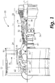
FIG. 1 is a schematic cross-sectional view of a gas turbine engine. -
FIG. 2 is a schematic cross-sectional view of a seal and seal cavity in an embodiment. -
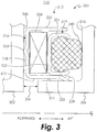
FIG. 3 is a schematic cross-sectional view of a seal and seal cavity in an embodiment. -
FIG. 4 is a schematic plan view of a wave spring in an embodiment. -
FIG. 5 is a schematic cross-sectional view of a seal and seal cavity in an embodiment. -
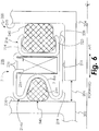
FIG. 6 is a schematic cross-sectional view of a seal and seal cavity in an embodiment. -
FIG. 7 is a schematic cross-sectional view of a portion of the seal ofFIG. 6 . -
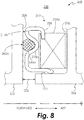
FIG. 8 is a schematic cross-sectional view of a seal and seal cavity in an embodiment. -
FIG. 9 is a schematic cross-sectional view of a seal and seal cavity in an embodiment. -
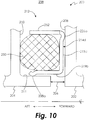
FIG. 10 is a schematic cross-sectional view of a seal and seal cavity in an embodiment. -
FIG. 11 is a schematic cross-sectional view of a seal and seal cavity in an embodiment. -
FIG. 12 is a schematic cross-sectional view of a seal and seal cavity in an embodiment. -
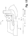
FIG. 13 is a schematic cross-sectional view of a seal and seal cavity in an embodiment. -
FIG. 14 is a schematic plan view of a portion of the seal ofFIG. 13 . -
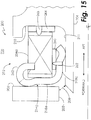
FIG. 15 is a schematic cross-sectional view of a seal and seal cavity in an embodiment. -
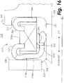
FIG. 16 is a schematic cross-sectional view of a seal and seal cavity in an embodiment. -
FIG. 17 is a schematic cross-sectional view of a seal and seal cavity in an embodiment. -
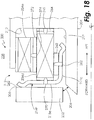
FIG. 18 is a schematic cross-sectional view of a seal and seal cavity in an embodiment. -
FIG. 19 is a schematic cross-sectional view of a seal and seal cavity in an embodiment. - For the purposes of promoting an understanding of the principles of the invention, reference will now be made to certain embodiments and specific language will be used to describe the same. It will nevertheless be understood that no limitation of the scope of the invention is thereby intended, and alterations and modifications in the illustrated device, and further applications of the principles of the invention as illustrated therein are herein contemplated as would normally occur to one skilled in the art to which the invention relates.
-
FIG. 1 schematically illustrates agas turbine engine 20. Thegas turbine engine 20 is disclosed herein as a two-spool turbofan that generally incorporates afan section 22, acompressor section 24, acombustor section 26 and aturbine section 28. Alternative engines might include an augmentor section (not shown) among other systems or features. Thefan section 22 drives air along a bypass flow path B in a bypass duct, while thecompressor section 24 drives air along a core flow path C for compression and communication into thecombustor section 26 then expansion through theturbine section 28. Although depicted as a two-spool turbofan gas turbine engine in the disclosed non-limiting embodiment, it should be understood that the concepts described herein are not limited to use with two-spool turbofans as the teachings may be applied to other types of turbine engines including three-spool architectures. - The
exemplary engine 20 generally includes alow speed spool 30 and ahigh speed spool 32 mounted for rotation about an engine central longitudinal axis A relative to an enginestatic structure 36 viaseveral bearing systems 38. It should be understood thatvarious bearing systems 38 at various locations may alternatively or additionally be provided, and the location ofbearing systems 38 may be varied as appropriate to the application. - The
low speed spool 30 generally includes aninner shaft 40 that interconnects afan 42, alow pressure compressor 44 and alow pressure turbine 46. Theinner shaft 40 is connected to thefan 42 through a speed change mechanism, which in exemplarygas turbine engine 20 is illustrated as a gearedarchitecture 48 to drive thefan 42 at a lower speed than thelow speed spool 30. Thehigh speed spool 32 includes anouter shaft 50 that interconnects ahigh pressure compressor 52 andhigh pressure turbine 54. Acombustor 56 is arranged inexemplary gas turbine 20 between thehigh pressure compressor 52 and thehigh pressure turbine 54. An enginestatic structure 36 is arranged generally between thehigh pressure turbine 54 and thelow pressure turbine 46. The enginestatic structure 36 furthersupports bearing systems 38 in theturbine section 28. Theinner shaft 40 and theouter shaft 50 are concentric and rotate via bearingsystems 38 about the engine central longitudinal axis A which is collinear with their longitudinal axes. - The core airflow is compressed by the
low pressure compressor 44 then thehigh pressure compressor 52, mixed and burned with fuel in thecombustor 56, then expanded over thehigh pressure turbine 54 andlow pressure turbine 46. Theturbines low speed spool 30 andhigh speed spool 32 in response to the expansion. It will be appreciated that each of the positions of thefan section 22,compressor section 24,combustor section 26,turbine section 28, and fandrive gear system 48 may be varied. For example,gear system 48 may be located aft ofcombustor section 26 or even aft ofturbine section 28, andfan section 22 may be positioned forward or aft of the location ofgear system 48. - The
engine 20 in one example is a high-bypass geared aircraft engine. In a further example, theengine 20 bypass ratio is greater than about six (6:1), with an example embodiment being greater than about ten (10:1), the gearedarchitecture 48 is an epicyclic gear train, such as a planetary gear system or other gear system, with a gear reduction ratio of greater than about 2.3 and thelow pressure turbine 46 has a pressure ratio that is greater than about five (5:1). In one disclosed embodiment, theengine 20 bypass ratio is greater than about ten (10:1), the fan diameter is significantly larger than that of thelow pressure compressor 44, and thelow pressure turbine 46 has a pressure ratio that is greater than about five (5:1).Low pressure turbine 46 pressure ratio is pressure measured prior to inlet oflow pressure turbine 46 as related to the pressure at the outlet of thelow pressure turbine 46 prior to an exhaust nozzle. The gearedarchitecture 48 may be an epicycle gear train, such as a planetary gear system or other gear system, with a gear reduction ratio of greater than about 2.3:1. It should be understood, however, that the above parameters are only exemplary of one embodiment of a geared architecture engine and that the present invention is applicable to other gas turbine engines including direct drive turbofans. - A significant amount of thrust is provided by the bypass flow B due to the high bypass ratio. The
fan section 22 of theengine 20 is designed for a particular flight condition -- typically cruise at about 0.8 Mach and about 35,000 feet (10,668 meters). The flight condition of 0.8 Mach and 35,000 ft (10,668 meters), with the engine at its best fuel consumption - also known as "bucket cruise Thrust Specific Fuel Consumption ('TSFC')" - is the industry standard parameter of lbm of fuel being burned divided by lbf of thrust the engine produces at that minimum point. "Low fan pressure ratio" is the pressure ratio across the fan blade alone, without a Fan Exit Guide Vane ("FEGV") system. The low fan pressure ratio as disclosed herein according to one non-limiting embodiment is less than about 1.45. "Low corrected fan tip speed" is the actual fan tip speed in ft/sec divided by an industry standard temperature correction of [(Tram °R) / (518.7 °R)]0.5. The "Low corrected fan tip speed" as disclosed herein according to one non-limiting embodiment is less than about 1150 ft / second (350.5 m/sec). -
FIG. 2 schematically illustrates a cross-sectional view of aseal cavity 100 formed by two axially-adjacent segmented or full-hoop turbine components nominal design clearance 106 exists between thecomponents seal cavity 100 lies a w-seal 108 formed from a material appropriate to the anticipated operating conditions (e.g., deflection, temperature change, pressure, etc.) of the w-seal 108, such a nickel-base alloy to name just one non-limiting example. - The design and material used in the construction of the w-
seal 108 causes it to be deflected both forward and aft within thecavity 100, thereby causing it to seat against thecomponents components clearance 106 to change. However, if subjected to significant deflections and/or temperature, a w-seal 108 may deform, causing it to become ineffective and potentially liberate. -
FIG. 3 schematically illustrates a cross-sectional view of aseal cavity 200 formed by two axially-adjacent segmented or fullhoop turbine components nominal design clearance 206 exists between thecomponents Component 202 includes asurface 208 facing theseal cavity 200 andcomponent 204 includessurfaces seal cavity 200. Within theseal cavity 200 lies aseal 212 formed from a material appropriate to the anticipated operating conditions of theseal 212, such as a high-temperature metal alloy, a high temperature ceramic material, a high temperature ceramic composite, or a combination of two or more of these, to name just a few non-limiting examples. Theseal 212 is formed from afirst seal section 214 and asecond seal section 216. Thefirst seal section 214 is generally C-shaped and includes abase 218, a majorinboard leg 219 and a majoroutboard leg 220. Thesecond seal section 216 is also generally C-shaped and includes abase 222, a minorinboard leg 223 and a minoroutboard leg 224. As used herein, the term "major outboard leg" is intended to mean only that the leg is further outboard than the "minor outboard leg". Similarly, the term "major inboard leg" is intended to mean only that the leg is further inboard than the "minor inboard leg". Thebases legs inboard leg 223 is supported by the majorinboard leg 219. Theseal 212 may include a coating and/or a sheath to provide increased wear resistance. - The
base 218 includes a forward substantially roundedportion 226 in contact with thesurface 208 such that theseal section 214 contacts thesurface 208 along a single circumferential line of contact (in the case of full hoop components) or a single semi-circumferential line of contact (in the case of split hoop components). As used herein, the phrases "circumferential line of contact" and "semi-circumferential line of contact" include lines with a nominal radial or axial thickness. Theseal section 214 also includes an aft substantiallyrounded end 228 in contact with thesurface 211 such that theseal section 214 contacts thesurface 211 along a single circumferential line of contact (in the case of full hoop components) or a single semi-circumferential line of contact (in the case of split hoop components). - A split
hoop wave spring 234 is disposed within the cavity defined by thebase 218, majorinboard leg 219 and majoroutboard leg 220 of theseal section 214, as well as thebase 222 of theseal section 216 in the embodiment ofFIG. 3 . A plan view of a portion of thewave spring 234 is illustrated inFIG. 4 . In the embodiment ofFIG. 5 , theseal section 214 does not include the majoroutboard leg 220, and theseal sections tabs 236 spaced around their radially outer circumference. Thetabs 236 wrap over the radially outer edge of thewave spring 234, thereby securing thewave spring 234 within the cavity defined by thebase 218 and majorinboard leg 219 of theseal section 214 and thebase 222 of theseal section 216. When both theseal section 214 and theseal section 216 includetabs 236, theseal 212 comprises a discrete assembly that may be handled and installed as a single piece. - The
seal 212 may include a full hoop high-temperature andcompliant seal 240, such as a woven or braided ceramic rope seal or flat fabric (for example, NEXTEL ceramic textile available from The 3M Company of Maplewood, Minnesota USA, to name just one non-limiting example) to partially seal stair-stepped gaps typical of segmented part interfaces of thecomponent 204. Thelegs seal section 216 mechanically trap thecompliant seal 240 while exposing enough of thecompliant seal 240 to allow it to conform to thesurface 210 of thecomponent 204. - Pressure in a
secondary flow cavity 238 is transmitted to theseal cavity 200 through an opening defined by thecomponents seal sections surface 208 of thecomponent 202, thecompliant seal 240 to seat against thesurface 210 of thecomponent 204, the minorinboard leg 223 to seat against the majorinboard leg 219, and the majorinboard leg 219 to seat against thesurface 211 of thecomponent 204. The load applied by minorinboard leg 223 to the majorinboard leg 219 helps the majorinboard leg 219 to seat against thesurface 211, thereby providing a secondary seal against flow that may leak past thecompliant seal 240/surface 210 interface andlegs secondary flow cavity 238 gases from reaching thedesign clearance 206 area and flow path. As the twocomponents seal sections seal sections seal 212 so that it remains in contact with bothcomponents components seal 212 move relative to one another. Because theseal sections components seal 212 is not substantially deflected by the relative movement between thecomponents - Furthermore, the circumferentially-oriented
wave spring 234 pushes theseal section 214 to remain in contact with theforward wall 208, and also pushes theseal section 216/compliant seal 240 to remain in contact with theaft wall 210 when thecavity 200 is not pressurized. This prevents theseal 212 from being damaged during transportation and installation, and also ensures that theseal 212 is instantly and positively pressurized/pressure-energized at engine start-up.Seal section 216 is split at one circumferential location to enable pressure to load theseal section 216 radially inward against theseal section 214.Seal section 214 may also optionally be split to create an additional sealing surface at the bottom of theseal cavity 200, as well as allowing theseal 212 to be packaged within a smaller radial design space. Leakage can be reduced significantly at the split location of eachseal section outer seal section 214. - In the embodiment of
FIG. 6 , theseal 212 may include a second full hoop high-temperature andcompliant seal 242, such as a woven or braided ceramic rope seal or flat fabric (for example, NEXTEL ceramic textile available from The 3M Company of Maplewood, Minnesota USA, to name just one non-limiting example) to partially seal stair-stepped gaps typical of segmented part interfaces of thecomponent 202 in some embodiments. Thecompliant seal 242 may be disposed between thebase 218a and thesurface 208 of thecomponent 202 by providing acavity 244 in thebase 218a in which thecompliant seal 242 may be retained in an embodiment. Thecompliant seal 242 may be mechanically attached to theseal section 214 by means offeatures 246 punched out of the base 218 as shown inFIG. 7 . The compliant seals 240, 242 add compliance to theseal 212 in the axial direction. - In the embodiment of
FIG. 8 , theseal 212 may include a full hoop or split hoop high-temperature andcompliant seal 242a, such as a woven or braided ceramic rope seal or flat fabric (for example, NEXTEL ceramic textile available from The 3M Company of Maplewood, Minnesota USA, to name just one non-limiting example), carried by a splithoop seal section 214b to partially seal stair-stepped gaps typical of segmented part interfaces of thecomponent 202 in some embodiments. Thecompliant seal 242a may be disposed between the base 218b and thesurface 208 of thecomponent 202 by providing acavity 244a in thebase 218b in which thecompliant seal 242a may be retained in an embodiment. Thecompliant seal 242a may be mechanically attached to theseal section 214b by means similar tofeatures 246 punched out of the base 218 as shown inFIG. 7 . Awave spring 234a is disposed between theseal section 214b and thecomponent 204 and biases theseal section 214b toward thesurface 208 of thecomponent 202. Thecompliant seal 242a adds compliance to theseal 212 in the axial direction. - In the embodiment of
FIG. 9 , theseal 212 may include a full hoop or split hoop high-temperature andcompliant seal 242b, such as a woven or braided ceramic rope seal or flat fabric (for example, NEXTEL ceramic textile available from The 3M Company of Maplewood, Minnesota USA, to name just one non-limiting example), carried by a splithoop seal section 214c to partially seal stair-stepped gaps typical of segmented part interfaces of thecomponent 202 in some embodiments. Thecompliant seal 242b may be disposed between the base 218c and thesurface 208 of thecomponent 202 by providing acavity 244b in thebase 218c in which thecompliant seal 242b may be retained in an embodiment. Theseal 212 may further include a full hoop or split hoop high-temperature andcompliant seal 242c, such as a woven or braided ceramic rope seal or flat fabric (for example, NEXTEL ceramic textile available from The 3M Company of Maplewood, Minnesota USA, to name just one non-limiting example), carried by the splithoop seal section 214c to partially seal against thecomponent 204 in some embodiments. Thecompliant seal 242c may be disposed between the majorinboard leg 219a and thesurface 211 of thecomponent 204 by providing acavity 244c in the majorinboard leg 219a in which thecompliant seal 242c may be retained in an embodiment. The compliant seals 242b and 242c may be mechanically attached to theseal section 214c by means offeatures 246 punched out of thebase 218c and majorinboard leg 219a. Awave spring 234b is disposed between theseal section 214c and thecomponent 204 and biases theseal section 214c toward thesurface 208 of thecomponent 202. Thecompliant seal 242b adds compliance to theseal 212 in the axial direction, while thecompliant seal 242c adds compliance to theseal 212 in the radial direction. - In the embodiment of
FIG. 10 , theseal 212 is formed from aseal section 214d that is generally L-shaped and includes abase 218d and a majorinboard leg 219b. Thebase 218d is oriented substantially radially, while the majorinboard leg 219b is oriented substantially axially. Thebase 218d includes a forward substantially roundedportion 226a in contact with thesurface 208 such that theseal section 214d contacts thesurface 208 along a single circumferential line of contact (in the case of full hoop components) or a single semi-circumferential line of contact (in the case of split hoop components). Theseal section 214d also includes an aft substantiallyrounded end 228a in contact with thesurface 211 such that theseal section 214d contacts thesurface 211 along a single circumferential line of contact (in the case of full hoop components) or a single semi-circumferential line of contact (in the case of split hoop components). - The
seal 212 may include a split hoop high-temperature andcompliant seal 250, such as a woven or braided ceramic rope seal or flat fabric (for example, NEXTEL ceramic textile available from The 3M Company of Maplewood, Minnesota USA, to name just one non-limiting example) to partially seal stair-stepped gaps typical of segmented part interfaces of thecomponent 204. Theseal section 214d includes a plurality oftabs 252 spaced around the radially outer circumference ofseal section 214d. Thetabs 252 wrap over the radially outer edge of thecompliant seal 250, thereby securing thecompliant seal 250 within the cavity defined by thebase 218d, majorinboard leg 219a, and thetabs 252, while allowing limited outward expansion of thecompliant seal 250 for increased resilience thereof. The splits in theseal section 214d and thecompliant seal 250 may be offset to minimize leakage, and/or a bridge seal may be disposed over the gaps. - The embodiment of
FIG. 11 is similar to the embodiment ofFIG. 10 . Theseal section 214e includes a continuous (except at the split location) majoroutboard leg 220a or a series oftabs 252. Awave spring 234c and optionally aflat ring 254 are disposed between thecompliant seal 250 and theseal section 214e. Sealing between the majoroutboard leg 220a and thecompliant seal 250 reduces leakage through the split in theseal section 214e, and resilience is not required from thecompliant seal 250 because it is provided by thewave spring 234c. In the embodiment ofFIG. 12 , an axially-extending protrusion is disposed onsurface 210 ofcomponent 204 to allow thelegs component 204 to allow additional sliding length for thecompliant seal 250. - The embodiment of
FIGs. 13 and14 illustrates aseal section 214f in contact withcomponents component 204 is segmented, there may be radial offsets between adjacent segments of thecomponent 204. In order to ensure better sealing between theseal section 214f and thesegmented component 204, theseal section 214f may include a plurality ofslots 258 formed therein to allow theseal section 214f to better conform to the stair-stepped surface of thecomponent 204. Provision of a plurality ofslots 258 may be made in any of the embodiments disclosed herein. - In the embodiment of
FIG. 15 , aseal section 214g is in contact withcomponents seal section 214g includes abase 218e and a majorinboard leg 219c. Anoptional spacer 260 may be disposed on the majorinboard leg 219c and optionally bonded to the majorinboard leg 219c at a plurality ofcircumferential locations 262 by any desired means, such as by laser welds or resistance welds to name just two non-limiting examples. Awave spring 234d is disposed on thespacer 260, thus thespacer 260 radially lifts thewave spring 234d. Thewave spring 234d may be retained by a plurality oftabs 262 disposed around the circumference of theseal section 214g. Ashield 264 contacts thewave spring 234d axially opposite theseal section 214g. Theshield 264 may be bonded to thewave spring 234d by any desired means, such as by a laser weld orresistance weld 265, to name just two non-limiting examples, placed approximately 180 degrees from a split location of thewave spring 234d to allow thewave spring 234d and shield 264 to grow freely relative to one another in the circumferential direction. Theshield 264 may be made from a low-strength, high-temperature and lubricious material to provide wear protection to thewave spring 234d against rubbing and point contact against stair-stepped edges of the segments of thecomponent 204. Theshield 264 may also provide thermal shielding and potentially improved sealing. In the embodiment ofFIG. 16 , theshield 264 is maintained in contact with thewave spring 234d by means of anextension 266 that loops over thewave spring 234d. As shown inFIG. 17 , a bridgingseal 268 may be positioned over the split inseal section 214g and mechanically attached to one side of the gap, with the other end of the bridgingseal 268 free to slide in response to differential thermal movement between theseal section 214g and the bridgingseal 268. - In the embodiment of
FIG. 18 , thetabs 262 may optionally be omitted and theseal section 214h may optionally be bonded to thewave spring 234d at alocation 270 by any desired means, such as by laser welds or resistance welds to name just two non-limiting examples. The seal may be loaded in the radial direction by asecond wave spring 234e. Thewave spring 234e may be bonded to aspacer 272 by any desired means, such as by laser welds or resistance welds to name just two non-limiting examples. Thewave spring 234e is disposed radially outboard from thewave spring 234d and biases thewave spring 234d andseal section 214h radially inward by bearing against thecomponent 204. In the embodiment ofFIG. 19 , a singleangled wave spring 234f is disposed between theseal section 214i and thecomponent 204 in order to apply both axial and radial loading to theseal section 214i. Afrustoconical spacer 274 may be disposed between thewave spring 234f and thecomponent 204 in some embodiments. - Compared to the
seal 108, thewave spring 234 exhibits improved resilience within the same design space since thewave spring 234 can be configured to have a much lower spring rate. Theseal sections components seal sections wave spring 234 is shielded from high conductive heat load, as well as convective and radiative heat loads from the gas path, by theseal sections seal 212 offers potentially improved sealing where a compliant material is used against segmented parts. Additionally, theseal 212 is less susceptible to distortion or breakage, which can cause leakage of gas past theseal 212 and/or liberation of the seal. Furthermore, theseal 212 exhibits improved vibration tolerance due to friction damping. - While the invention has been illustrated and described in detail in the drawings and foregoing description, the same is to be considered as illustrative and not restrictive in character, it being understood that only certain embodiments have been shown and described and that all changes and modifications that come within the scope of the claims are desired to be protected.
Claims (14)
- A seal for sealing a space defined by first and second adjacent components disposed about an axial centerline, the seal comprising:a substantially L-shaped first seal section including a first base and a first leg extending from the first base;a substantially C-shaped second seal section including a second base and second and third legs extending from the second base and defining a cavity;a wave spring disposed between the first and second seal sections and operative to bias the first seal section away from the second seal section; anda compliant seal partially disposed within the cavity;wherein the first and second seal sections are configured to move relative to one another.
- A seal for sealing a space defined by first and second adjacent components disposed about an axial centerline, the seal comprising:a first seal section including a first base and first and second legs extending from the first base, the first base including a first cavity formed therein;a substantially C-shaped second seal section including a second base and third and fourth legs extending from the second base and defining a second cavity;a wave spring disposed between the first and second seal sections and operative to bias the first seal section away from the second seal section;a first compliant seal partially disposed within the first cavity; anda second compliant seal partially disposed within the second cavity;wherein the first and second seal sections are configured to move relative to one another.
- A seal for sealing a space defined by first and second adjacent components disposed about an axial centerline, the seal comprising:a seal section including a first base and first and second legs extending from the first base, the first base including a cavity formed therein;a wave spring disposed between the first seal section and the first component and operative to bias the first seal section toward the second component; anda compliant seal partially disposed within the cavity.
- A seal for sealing a space defined by first and second adjacent components disposed about an axial centerline, the seal comprising:a seal section including a first base and first and second legs extending from the first base, the first base including a first cavity formed therein and the second leg including a second cavity formed therein;a wave spring disposed between the first seal sections and the first component and operative to bias the first seal section toward the second component;a first compliant seal partially disposed within the first cavity; anda second compliant seal partially disposed within the second cavity.
- A seal for sealing a space defined by first and second adjacent components disposed about an axial centerline, the seal comprising:a substantially L-shaped first seal section including a first base and a first leg extending from the first base;a plurality of tabs extending from the first base, wherein the first base, the first leg, and the plurality of tabs defining a cavity; anda compliant seal partially disposed within the cavity.
- A seal for sealing a space defined by first and second adjacent components disposed about an axial centerline, the seal comprising:a substantially C-shaped first seal section including a first base and first and second legs extending from the first base and defining a cavity;a compliant seal partially disposed within the cavity;a wave spring disposed within the cavity;a flat ring disposed between the compliant seal and the wave spring;wherein the wave spring is operative to bias the compliant seal away from the first seal section.
- A seal for sealing a space defined by first and second adjacent components disposed about an axial centerline, the seal comprising:a seal section including a first base and a first leg extending from the first base, the first leg including a plurality of slots formed therein; anda wave spring disposed between the first seal section and the first component and operative to bias the first seal section toward the second component.
- A seal for sealing a space defined by first and second adjacent components disposed about an axial centerline, the seal comprising:a seal section including a first base and a first leg extending from the first base;a wave spring disposed between the first seal section and the first component and operative to bias the first seal section toward the second component;a flat ring spacer disposed between the wave spring and the first component; anda plurality of tabs extending from the first base and over a radially outer portion of the wave spring.
- A seal as recited in claim 8, for sealing a space defined by first and second adjacent components disposed about an axial centerline, the seal further comprising:
a plurality of second tabs extending from the flat ring spacer and over the radially outer portion of the wave spring. - A seal for sealing a space defined by first and second adjacent components disposed about an axial centerline, the seal comprising:a split hoop seal section including a first base and a first leg extending from the first base, wherein a gap is defined by the first base and the first leg;a wave spring disposed between the first seal section and the first component and operative to bias the first seal section toward the second component;a flat ring spacer disposed between the wave spring and the first component;a plurality of tabs extending from the first base and over a radially outer portion of the wave spring; anda bridging seal disposed over said gap.
- A seal for sealing a space defined by first and second adjacent components disposed about an axial centerline, the seal comprising:a seal section including a first base and a first leg extending from the first base;a first wave spring disposed between the first seal section and the first component and operative to bias the first seal section toward the second component;a flat ring spacer disposed between the wave spring and the first component; anda second wave spring disposed between the first wave spring and the first component such that the first wave spring is biased radially inboard.
- A seal for sealing a space defined by first and second adjacent components disposed about an axial centerline, the seal comprising:a seal section including a first base and first and second legs extending from the first base;a wave spring disposed between the first seal section and the first component and operative to axially bias the first seal section toward the second component and to bias the first seal section radially inboard; anda frustoconical spacer disposed between the wave spring and the first component.
- A system, comprising:a first component including a first surface;a second component including a second surface, the second component disposed adjacent the first component and defining a seal cavity therebetween;wherein the first and second components are disposed about an axial centerline; anda seal disposed in the seal cavity, the seal including:wherein the first and second seal sections are configured to move relative to one another.a first substantially C-shaped seal section including a first base and first and second legs extending from the first base and defining a first cavity;a second substantially C-shaped seal section including a second base and third and fourth legs extending from the second base and defining a second cavity, the second seal section at least partially disposed within the first cavity;a wave spring disposed within the first cavity between the first and second seal sections and operative to bias the first seal section away from the second seal section; anda compliant seal partially disposed within the second cavity;
- A seal for sealing a space defined by first and second adjacent components disposed about an axial centerline, the seal comprising:a first substantially C-shaped seal section including a first base and first and second legs extending from the first base and defining a first cavity;a second substantially C-shaped seal section including a second base and third and fourth legs extending from the second base and defining a second cavity, the second seal section at least partially disposed within the first cavity;a wave spring disposed within the first cavity between the first and second seal sections and operative to bias the first seal section away from the second seal section; anda compliant seal partially disposed within the second cavity;wherein the first and second seal sections are configured to move relative to one another.
Applications Claiming Priority (2)
| Application Number | Priority Date | Filing Date | Title |
|---|---|---|---|
| US201462068519P | 2014-10-24 | 2014-10-24 | |
| EP15190612.0A EP3012497B1 (en) | 2014-10-24 | 2015-10-20 | Sliding seal |
Related Parent Applications (2)
| Application Number | Title | Priority Date | Filing Date |
|---|---|---|---|
| EP15190612.0A Division EP3012497B1 (en) | 2014-10-24 | 2015-10-20 | Sliding seal |
| EP15190612.0A Division-Into EP3012497B1 (en) | 2014-10-24 | 2015-10-20 | Sliding seal |
Publications (2)
| Publication Number | Publication Date |
|---|---|
| EP3575644A1 true EP3575644A1 (en) | 2019-12-04 |
| EP3575644B1 EP3575644B1 (en) | 2022-03-30 |
Family
ID=54541936
Family Applications (2)
| Application Number | Title | Priority Date | Filing Date |
|---|---|---|---|
| EP15190612.0A Active EP3012497B1 (en) | 2014-10-24 | 2015-10-20 | Sliding seal |
| EP19186490.9A Active EP3575644B1 (en) | 2014-10-24 | 2015-10-20 | Sliding seal |
Family Applications Before (1)
| Application Number | Title | Priority Date | Filing Date |
|---|---|---|---|
| EP15190612.0A Active EP3012497B1 (en) | 2014-10-24 | 2015-10-20 | Sliding seal |
Country Status (2)
| Country | Link |
|---|---|
| US (2) | US10370993B2 (en) |
| EP (2) | EP3012497B1 (en) |
Families Citing this family (8)
| Publication number | Priority date | Publication date | Assignee | Title |
|---|---|---|---|---|
| US10400896B2 (en) | 2014-08-28 | 2019-09-03 | United Technologies Corporation | Dual-ended brush seal assembly and method of manufacture |
| US9988919B2 (en) * | 2014-10-24 | 2018-06-05 | United Technologies Corporation | Dual compliant seal |
| US10260364B2 (en) * | 2015-03-09 | 2019-04-16 | United Technologies Corporation | Sliding seal |
| US10487687B1 (en) * | 2016-09-15 | 2019-11-26 | United Technologies Corporation | Gas turbine engine having a seal damper assembly |
| US11486497B2 (en) | 2017-07-19 | 2022-11-01 | Raytheon Technologies Corporation | Compact brush seal |
| KR102003249B1 (en) * | 2018-01-17 | 2019-07-24 | 주식회사 신양메카텍 | A robot hand changer with improved operational reliability |
| US11781440B2 (en) * | 2021-03-09 | 2023-10-10 | Rtx Corporation | Scalloped mateface seal arrangement for CMC platforms |
| US11905837B2 (en) * | 2022-03-23 | 2024-02-20 | General Electric Company | Sealing system including a seal assembly between components |
Citations (3)
| Publication number | Priority date | Publication date | Assignee | Title |
|---|---|---|---|---|
| US3706459A (en) * | 1970-04-29 | 1972-12-19 | Goetzewerke | Oil seal for rotary piston machines |
| GB2385643A (en) * | 2002-02-20 | 2003-08-27 | Cross Mfg Company | A jet pipe assembly including at least one joint and a fluid seal assembly therefor |
| US20130234407A1 (en) * | 2012-03-09 | 2013-09-12 | Russell P. Parrish | Seal assembly |
Family Cites Families (15)
| Publication number | Priority date | Publication date | Assignee | Title |
|---|---|---|---|---|
| US3068016A (en) * | 1958-03-31 | 1962-12-11 | Gen Motors Corp | High temperature seal |
| US3279803A (en) | 1962-11-30 | 1966-10-18 | Chicago Rawhide Mfg Co | Face lined seals |
| JPS60118030U (en) * | 1984-01-19 | 1985-08-09 | 株式会社 大金製作所 | Diaphragm spring retention structure of clutch cover assembly |
| US4602795A (en) * | 1985-12-06 | 1986-07-29 | United Technologies Corporation | Thermally expansive slip joint for formed sheet metal seals |
| US4783085A (en) | 1987-03-27 | 1988-11-08 | United Technologies Corporation | Segmented rigid sliding seal |
| US5251914A (en) * | 1987-05-28 | 1993-10-12 | Tatum David M | Sealing assembly for relatively movable members |
| US5014917A (en) | 1989-11-27 | 1991-05-14 | The United States Of America As Represented By The Administrator Of The National Aeronautics And Space Administration | High-temperature, flexible, thermal barrier seal |
| US5078412A (en) * | 1991-01-07 | 1992-01-07 | United Technologies Corporation | Separately loaded strip seal |
| US5893564A (en) * | 1997-05-23 | 1999-04-13 | Meritor Heavy Vehicle Systems, Llc | Mechanical face seal assembly |
| RU2302534C2 (en) | 2001-12-11 | 2007-07-10 | Альстом (Свитзерлэнд) Лтд. | Gas-turbine device |
| GB2417528B (en) | 2004-08-23 | 2008-08-06 | Alstom Technology Ltd | Improved rope seal for gas turbine engines |
| US8016297B2 (en) | 2008-03-27 | 2011-09-13 | United Technologies Corporation | Gas turbine engine seals and engines incorporating such seals |
| US8491259B2 (en) * | 2009-08-26 | 2013-07-23 | Siemens Energy, Inc. | Seal system between transition duct exit section and turbine inlet in a gas turbine engine |
| US8651497B2 (en) * | 2011-06-17 | 2014-02-18 | United Technologies Corporation | Winged W-seal |
| US20130113168A1 (en) | 2011-11-04 | 2013-05-09 | Paul M. Lutjen | Metal gasket for a gas turbine engine |
-
2015
- 2015-08-20 US US14/830,910 patent/US10370993B2/en active Active
- 2015-10-20 EP EP15190612.0A patent/EP3012497B1/en active Active
- 2015-10-20 EP EP19186490.9A patent/EP3575644B1/en active Active
-
2019
- 2019-08-05 US US16/531,571 patent/US11098606B2/en active Active
Patent Citations (3)
| Publication number | Priority date | Publication date | Assignee | Title |
|---|---|---|---|---|
| US3706459A (en) * | 1970-04-29 | 1972-12-19 | Goetzewerke | Oil seal for rotary piston machines |
| GB2385643A (en) * | 2002-02-20 | 2003-08-27 | Cross Mfg Company | A jet pipe assembly including at least one joint and a fluid seal assembly therefor |
| US20130234407A1 (en) * | 2012-03-09 | 2013-09-12 | Russell P. Parrish | Seal assembly |
Also Published As
| Publication number | Publication date |
|---|---|
| US10370993B2 (en) | 2019-08-06 |
| US11098606B2 (en) | 2021-08-24 |
| EP3575644B1 (en) | 2022-03-30 |
| US20190353044A1 (en) | 2019-11-21 |
| EP3012497B1 (en) | 2019-08-28 |
| US20160115814A1 (en) | 2016-04-28 |
| EP3012497A1 (en) | 2016-04-27 |
Similar Documents
| Publication | Publication Date | Title |
|---|---|---|
| US11098606B2 (en) | Sliding seal | |
| US11021983B2 (en) | Multi-piece seal | |
| US9988919B2 (en) | Dual compliant seal | |
| US10641119B2 (en) | Sliding seal | |
| US11085314B2 (en) | Sliding seal | |
| EP3023599B1 (en) | Bifurcated sliding seal | |
| US11365641B2 (en) | Bifurcated sliding seal | |
| EP3012494B1 (en) | Sliding seal | |
| EP3012492B1 (en) | Sliding seal | |
| US20160258308A1 (en) | Sliding compliant seal | |
| US10208613B2 (en) | Segmented seal | |
| US11359504B2 (en) | Sliding seal | |
| US10167730B2 (en) | Sliding seal | |
| US9587503B2 (en) | Hinged seal |
Legal Events
| Date | Code | Title | Description |
|---|---|---|---|
| PUAI | Public reference made under article 153(3) epc to a published international application that has entered the european phase |
Free format text: ORIGINAL CODE: 0009012 |
|
| STAA | Information on the status of an ep patent application or granted ep patent |
Free format text: STATUS: THE APPLICATION HAS BEEN PUBLISHED |
|
| AC | Divisional application: reference to earlier application |
Ref document number: 3012497 Country of ref document: EP Kind code of ref document: P |
|
| AK | Designated contracting states |
Kind code of ref document: A1 Designated state(s): AL AT BE BG CH CY CZ DE DK EE ES FI FR GB GR HR HU IE IS IT LI LT LU LV MC MK MT NL NO PL PT RO RS SE SI SK SM TR |
|
| STAA | Information on the status of an ep patent application or granted ep patent |
Free format text: STATUS: REQUEST FOR EXAMINATION WAS MADE |
|
| 17P | Request for examination filed |
Effective date: 20200604 |
|
| RBV | Designated contracting states (corrected) |
Designated state(s): AL AT BE BG CH CY CZ DE DK EE ES FI FR GB GR HR HU IE IS IT LI LT LU LV MC MK MT NL NO PL PT RO RS SE SI SK SM TR |
|
| STAA | Information on the status of an ep patent application or granted ep patent |
Free format text: STATUS: EXAMINATION IS IN PROGRESS |
|
| 17Q | First examination report despatched |
Effective date: 20210114 |
|
| RAP1 | Party data changed (applicant data changed or rights of an application transferred) |
Owner name: RAYTHEON TECHNOLOGIES CORPORATION |
|
| GRAP | Despatch of communication of intention to grant a patent |
Free format text: ORIGINAL CODE: EPIDOSNIGR1 |
|
| STAA | Information on the status of an ep patent application or granted ep patent |
Free format text: STATUS: GRANT OF PATENT IS INTENDED |
|
| INTG | Intention to grant announced |
Effective date: 20211109 |
|
| GRAS | Grant fee paid |
Free format text: ORIGINAL CODE: EPIDOSNIGR3 |
|
| GRAA | (expected) grant |
Free format text: ORIGINAL CODE: 0009210 |
|
| STAA | Information on the status of an ep patent application or granted ep patent |
Free format text: STATUS: THE PATENT HAS BEEN GRANTED |
|
| AC | Divisional application: reference to earlier application |
Ref document number: 3012497 Country of ref document: EP Kind code of ref document: P |
|
| AK | Designated contracting states |
Kind code of ref document: B1 Designated state(s): AL AT BE BG CH CY CZ DE DK EE ES FI FR GB GR HR HU IE IS IT LI LT LU LV MC MK MT NL NO PL PT RO RS SE SI SK SM TR |
|
| REG | Reference to a national code |
Ref country code: GB Ref legal event code: FG4D |
|
| REG | Reference to a national code |
Ref country code: CH Ref legal event code: EP |
|
| REG | Reference to a national code |
Ref country code: AT Ref legal event code: REF Ref document number: 1479487 Country of ref document: AT Kind code of ref document: T Effective date: 20220415 |
|
| REG | Reference to a national code |
Ref country code: DE Ref legal event code: R096 Ref document number: 602015077966 Country of ref document: DE |
|
| REG | Reference to a national code |
Ref country code: IE Ref legal event code: FG4D |
|
| REG | Reference to a national code |
Ref country code: LT Ref legal event code: MG9D |
|
| PG25 | Lapsed in a contracting state [announced via postgrant information from national office to epo] |
Ref country code: SE Free format text: LAPSE BECAUSE OF FAILURE TO SUBMIT A TRANSLATION OF THE DESCRIPTION OR TO PAY THE FEE WITHIN THE PRESCRIBED TIME-LIMIT Effective date: 20220330 Ref country code: RS Free format text: LAPSE BECAUSE OF FAILURE TO SUBMIT A TRANSLATION OF THE DESCRIPTION OR TO PAY THE FEE WITHIN THE PRESCRIBED TIME-LIMIT Effective date: 20220330 Ref country code: NO Free format text: LAPSE BECAUSE OF FAILURE TO SUBMIT A TRANSLATION OF THE DESCRIPTION OR TO PAY THE FEE WITHIN THE PRESCRIBED TIME-LIMIT Effective date: 20220630 Ref country code: LT Free format text: LAPSE BECAUSE OF FAILURE TO SUBMIT A TRANSLATION OF THE DESCRIPTION OR TO PAY THE FEE WITHIN THE PRESCRIBED TIME-LIMIT Effective date: 20220330 Ref country code: HR Free format text: LAPSE BECAUSE OF FAILURE TO SUBMIT A TRANSLATION OF THE DESCRIPTION OR TO PAY THE FEE WITHIN THE PRESCRIBED TIME-LIMIT Effective date: 20220330 Ref country code: BG Free format text: LAPSE BECAUSE OF FAILURE TO SUBMIT A TRANSLATION OF THE DESCRIPTION OR TO PAY THE FEE WITHIN THE PRESCRIBED TIME-LIMIT Effective date: 20220630 |
|
| REG | Reference to a national code |
Ref country code: NL Ref legal event code: MP Effective date: 20220330 |
|
| REG | Reference to a national code |
Ref country code: AT Ref legal event code: MK05 Ref document number: 1479487 Country of ref document: AT Kind code of ref document: T Effective date: 20220330 |
|
| PG25 | Lapsed in a contracting state [announced via postgrant information from national office to epo] |
Ref country code: LV Free format text: LAPSE BECAUSE OF FAILURE TO SUBMIT A TRANSLATION OF THE DESCRIPTION OR TO PAY THE FEE WITHIN THE PRESCRIBED TIME-LIMIT Effective date: 20220330 Ref country code: GR Free format text: LAPSE BECAUSE OF FAILURE TO SUBMIT A TRANSLATION OF THE DESCRIPTION OR TO PAY THE FEE WITHIN THE PRESCRIBED TIME-LIMIT Effective date: 20220701 Ref country code: FI Free format text: LAPSE BECAUSE OF FAILURE TO SUBMIT A TRANSLATION OF THE DESCRIPTION OR TO PAY THE FEE WITHIN THE PRESCRIBED TIME-LIMIT Effective date: 20220330 |
|
| PG25 | Lapsed in a contracting state [announced via postgrant information from national office to epo] |
Ref country code: NL Free format text: LAPSE BECAUSE OF FAILURE TO SUBMIT A TRANSLATION OF THE DESCRIPTION OR TO PAY THE FEE WITHIN THE PRESCRIBED TIME-LIMIT Effective date: 20220330 |
|
| PG25 | Lapsed in a contracting state [announced via postgrant information from national office to epo] |
Ref country code: SM Free format text: LAPSE BECAUSE OF FAILURE TO SUBMIT A TRANSLATION OF THE DESCRIPTION OR TO PAY THE FEE WITHIN THE PRESCRIBED TIME-LIMIT Effective date: 20220330 Ref country code: SK Free format text: LAPSE BECAUSE OF FAILURE TO SUBMIT A TRANSLATION OF THE DESCRIPTION OR TO PAY THE FEE WITHIN THE PRESCRIBED TIME-LIMIT Effective date: 20220330 Ref country code: RO Free format text: LAPSE BECAUSE OF FAILURE TO SUBMIT A TRANSLATION OF THE DESCRIPTION OR TO PAY THE FEE WITHIN THE PRESCRIBED TIME-LIMIT Effective date: 20220330 Ref country code: PT Free format text: LAPSE BECAUSE OF FAILURE TO SUBMIT A TRANSLATION OF THE DESCRIPTION OR TO PAY THE FEE WITHIN THE PRESCRIBED TIME-LIMIT Effective date: 20220801 Ref country code: ES Free format text: LAPSE BECAUSE OF FAILURE TO SUBMIT A TRANSLATION OF THE DESCRIPTION OR TO PAY THE FEE WITHIN THE PRESCRIBED TIME-LIMIT Effective date: 20220330 Ref country code: EE Free format text: LAPSE BECAUSE OF FAILURE TO SUBMIT A TRANSLATION OF THE DESCRIPTION OR TO PAY THE FEE WITHIN THE PRESCRIBED TIME-LIMIT Effective date: 20220330 Ref country code: CZ Free format text: LAPSE BECAUSE OF FAILURE TO SUBMIT A TRANSLATION OF THE DESCRIPTION OR TO PAY THE FEE WITHIN THE PRESCRIBED TIME-LIMIT Effective date: 20220330 Ref country code: AT Free format text: LAPSE BECAUSE OF FAILURE TO SUBMIT A TRANSLATION OF THE DESCRIPTION OR TO PAY THE FEE WITHIN THE PRESCRIBED TIME-LIMIT Effective date: 20220330 |
|
| PG25 | Lapsed in a contracting state [announced via postgrant information from national office to epo] |
Ref country code: PL Free format text: LAPSE BECAUSE OF FAILURE TO SUBMIT A TRANSLATION OF THE DESCRIPTION OR TO PAY THE FEE WITHIN THE PRESCRIBED TIME-LIMIT Effective date: 20220330 Ref country code: IS Free format text: LAPSE BECAUSE OF FAILURE TO SUBMIT A TRANSLATION OF THE DESCRIPTION OR TO PAY THE FEE WITHIN THE PRESCRIBED TIME-LIMIT Effective date: 20220730 Ref country code: AL Free format text: LAPSE BECAUSE OF FAILURE TO SUBMIT A TRANSLATION OF THE DESCRIPTION OR TO PAY THE FEE WITHIN THE PRESCRIBED TIME-LIMIT Effective date: 20220330 |
|
| REG | Reference to a national code |
Ref country code: DE Ref legal event code: R097 Ref document number: 602015077966 Country of ref document: DE |
|
| PG25 | Lapsed in a contracting state [announced via postgrant information from national office to epo] |
Ref country code: DK Free format text: LAPSE BECAUSE OF FAILURE TO SUBMIT A TRANSLATION OF THE DESCRIPTION OR TO PAY THE FEE WITHIN THE PRESCRIBED TIME-LIMIT Effective date: 20220330 |
|
| PLBE | No opposition filed within time limit |
Free format text: ORIGINAL CODE: 0009261 |
|
| STAA | Information on the status of an ep patent application or granted ep patent |
Free format text: STATUS: NO OPPOSITION FILED WITHIN TIME LIMIT |
|
| 26N | No opposition filed |
Effective date: 20230103 |
|
| PG25 | Lapsed in a contracting state [announced via postgrant information from national office to epo] |
Ref country code: SI Free format text: LAPSE BECAUSE OF FAILURE TO SUBMIT A TRANSLATION OF THE DESCRIPTION OR TO PAY THE FEE WITHIN THE PRESCRIBED TIME-LIMIT Effective date: 20220330 Ref country code: MC Free format text: LAPSE BECAUSE OF FAILURE TO SUBMIT A TRANSLATION OF THE DESCRIPTION OR TO PAY THE FEE WITHIN THE PRESCRIBED TIME-LIMIT Effective date: 20220330 |
|
| REG | Reference to a national code |
Ref country code: CH Ref legal event code: PL |
|
| REG | Reference to a national code |
Ref country code: BE Ref legal event code: MM Effective date: 20221031 |
|
| P01 | Opt-out of the competence of the unified patent court (upc) registered |
Effective date: 20230521 |
|
| PG25 | Lapsed in a contracting state [announced via postgrant information from national office to epo] |
Ref country code: LU Free format text: LAPSE BECAUSE OF NON-PAYMENT OF DUE FEES Effective date: 20221020 |
|
| PG25 | Lapsed in a contracting state [announced via postgrant information from national office to epo] |
Ref country code: LI Free format text: LAPSE BECAUSE OF NON-PAYMENT OF DUE FEES Effective date: 20221031 Ref country code: IT Free format text: LAPSE BECAUSE OF FAILURE TO SUBMIT A TRANSLATION OF THE DESCRIPTION OR TO PAY THE FEE WITHIN THE PRESCRIBED TIME-LIMIT Effective date: 20220330 Ref country code: CH Free format text: LAPSE BECAUSE OF NON-PAYMENT OF DUE FEES Effective date: 20221031 |
|
| PG25 | Lapsed in a contracting state [announced via postgrant information from national office to epo] |
Ref country code: BE Free format text: LAPSE BECAUSE OF NON-PAYMENT OF DUE FEES Effective date: 20221031 |
|
| PG25 | Lapsed in a contracting state [announced via postgrant information from national office to epo] |
Ref country code: IE Free format text: LAPSE BECAUSE OF NON-PAYMENT OF DUE FEES Effective date: 20221020 |
|
| PG25 | Lapsed in a contracting state [announced via postgrant information from national office to epo] |
Ref country code: HU Free format text: LAPSE BECAUSE OF FAILURE TO SUBMIT A TRANSLATION OF THE DESCRIPTION OR TO PAY THE FEE WITHIN THE PRESCRIBED TIME-LIMIT; INVALID AB INITIO Effective date: 20151020 |
|
| PG25 | Lapsed in a contracting state [announced via postgrant information from national office to epo] |
Ref country code: CY Free format text: LAPSE BECAUSE OF FAILURE TO SUBMIT A TRANSLATION OF THE DESCRIPTION OR TO PAY THE FEE WITHIN THE PRESCRIBED TIME-LIMIT Effective date: 20220330 |
|
| PG25 | Lapsed in a contracting state [announced via postgrant information from national office to epo] |
Ref country code: MK Free format text: LAPSE BECAUSE OF FAILURE TO SUBMIT A TRANSLATION OF THE DESCRIPTION OR TO PAY THE FEE WITHIN THE PRESCRIBED TIME-LIMIT Effective date: 20220330 |
|
| PG25 | Lapsed in a contracting state [announced via postgrant information from national office to epo] |
Ref country code: MT Free format text: LAPSE BECAUSE OF FAILURE TO SUBMIT A TRANSLATION OF THE DESCRIPTION OR TO PAY THE FEE WITHIN THE PRESCRIBED TIME-LIMIT Effective date: 20220330 |
|
| REG | Reference to a national code |
Ref country code: DE Ref legal event code: R081 Ref document number: 602015077966 Country of ref document: DE Owner name: RTX CORPORATION (N.D.GES.D. STAATES DELAWARE),, US Free format text: FORMER OWNER: RAYTHEON TECHNOLOGIES CORPORATION, FARMINGTON, CT, US |
|
| PGFP | Annual fee paid to national office [announced via postgrant information from national office to epo] |
Ref country code: GB Payment date: 20250923 Year of fee payment: 11 |
|
| PGFP | Annual fee paid to national office [announced via postgrant information from national office to epo] |
Ref country code: FR Payment date: 20250924 Year of fee payment: 11 |
|
| PG25 | Lapsed in a contracting state [announced via postgrant information from national office to epo] |
Ref country code: TR Free format text: LAPSE BECAUSE OF FAILURE TO SUBMIT A TRANSLATION OF THE DESCRIPTION OR TO PAY THE FEE WITHIN THE PRESCRIBED TIME-LIMIT Effective date: 20220330 |
|
| PGFP | Annual fee paid to national office [announced via postgrant information from national office to epo] |
Ref country code: DE Payment date: 20250923 Year of fee payment: 11 |