EP3575586B1 - Evaporative fuel treatment apparatus and control method for evaporative fuel treatment apparatus - Google Patents
Evaporative fuel treatment apparatus and control method for evaporative fuel treatment apparatus Download PDFInfo
- Publication number
- EP3575586B1 EP3575586B1 EP19176268.1A EP19176268A EP3575586B1 EP 3575586 B1 EP3575586 B1 EP 3575586B1 EP 19176268 A EP19176268 A EP 19176268A EP 3575586 B1 EP3575586 B1 EP 3575586B1
- Authority
- EP
- European Patent Office
- Prior art keywords
- valve
- pressure
- tank
- control unit
- canister
- Prior art date
- Legal status (The legal status is an assumption and is not a legal conclusion. Google has not performed a legal analysis and makes no representation as to the accuracy of the status listed.)
- Not-in-force
Links
Images


Classifications
-
- F—MECHANICAL ENGINEERING; LIGHTING; HEATING; WEAPONS; BLASTING
- F02—COMBUSTION ENGINES; HOT-GAS OR COMBUSTION-PRODUCT ENGINE PLANTS
- F02D—CONTROLLING COMBUSTION ENGINES
- F02D41/00—Electrical control of supply of combustible mixture or its constituents
- F02D41/0025—Controlling engines characterised by use of non-liquid fuels, pluralities of fuels, or non-fuel substances added to the combustible mixtures
- F02D41/003—Adding fuel vapours, e.g. drawn from engine fuel reservoir
-
- F—MECHANICAL ENGINEERING; LIGHTING; HEATING; WEAPONS; BLASTING
- F02—COMBUSTION ENGINES; HOT-GAS OR COMBUSTION-PRODUCT ENGINE PLANTS
- F02M—SUPPLYING COMBUSTION ENGINES IN GENERAL WITH COMBUSTIBLE MIXTURES OR CONSTITUENTS THEREOF
- F02M25/00—Engine-pertinent apparatus for adding non-fuel substances or small quantities of secondary fuel to combustion-air, main fuel or fuel-air mixture
- F02M25/08—Engine-pertinent apparatus for adding non-fuel substances or small quantities of secondary fuel to combustion-air, main fuel or fuel-air mixture adding fuel vapours drawn from engine fuel reservoir
- F02M25/0809—Judging failure of purge control system
-
- B—PERFORMING OPERATIONS; TRANSPORTING
- B60—VEHICLES IN GENERAL
- B60K—ARRANGEMENT OR MOUNTING OF PROPULSION UNITS OR OF TRANSMISSIONS IN VEHICLES; ARRANGEMENT OR MOUNTING OF PLURAL DIVERSE PRIME-MOVERS IN VEHICLES; AUXILIARY DRIVES FOR VEHICLES; INSTRUMENTATION OR DASHBOARDS FOR VEHICLES; ARRANGEMENTS IN CONNECTION WITH COOLING, AIR INTAKE, GAS EXHAUST OR FUEL SUPPLY OF PROPULSION UNITS IN VEHICLES
- B60K15/00—Arrangement in connection with fuel supply of combustion engines or other fuel consuming energy converters, e.g. fuel cells; Mounting or construction of fuel tanks
- B60K15/03—Fuel tanks
- B60K15/035—Fuel tanks characterised by venting means
- B60K15/03504—Fuel tanks characterised by venting means adapted to avoid loss of fuel or fuel vapour, e.g. with vapour recovery systems
-
- F—MECHANICAL ENGINEERING; LIGHTING; HEATING; WEAPONS; BLASTING
- F02—COMBUSTION ENGINES; HOT-GAS OR COMBUSTION-PRODUCT ENGINE PLANTS
- F02D—CONTROLLING COMBUSTION ENGINES
- F02D41/00—Electrical control of supply of combustible mixture or its constituents
- F02D41/0025—Controlling engines characterised by use of non-liquid fuels, pluralities of fuels, or non-fuel substances added to the combustible mixtures
- F02D41/003—Adding fuel vapours, e.g. drawn from engine fuel reservoir
- F02D41/0032—Controlling the purging of the canister as a function of the engine operating conditions
- F02D41/004—Control of the valve or purge actuator, e.g. duty cycle, closed loop control of position
-
- F—MECHANICAL ENGINEERING; LIGHTING; HEATING; WEAPONS; BLASTING
- F02—COMBUSTION ENGINES; HOT-GAS OR COMBUSTION-PRODUCT ENGINE PLANTS
- F02D—CONTROLLING COMBUSTION ENGINES
- F02D41/00—Electrical control of supply of combustible mixture or its constituents
- F02D41/02—Circuit arrangements for generating control signals
- F02D41/14—Introducing closed-loop corrections
- F02D41/1401—Introducing closed-loop corrections characterised by the control or regulation method
-
- F—MECHANICAL ENGINEERING; LIGHTING; HEATING; WEAPONS; BLASTING
- F02—COMBUSTION ENGINES; HOT-GAS OR COMBUSTION-PRODUCT ENGINE PLANTS
- F02D—CONTROLLING COMBUSTION ENGINES
- F02D41/00—Electrical control of supply of combustible mixture or its constituents
- F02D41/24—Electrical control of supply of combustible mixture or its constituents characterised by the use of digital means
- F02D41/2406—Electrical control of supply of combustible mixture or its constituents characterised by the use of digital means using essentially read only memories
- F02D41/2425—Particular ways of programming the data
- F02D41/2429—Methods of calibrating or learning
- F02D41/2451—Methods of calibrating or learning characterised by what is learned or calibrated
- F02D41/2464—Characteristics of actuators
-
- F—MECHANICAL ENGINEERING; LIGHTING; HEATING; WEAPONS; BLASTING
- F02—COMBUSTION ENGINES; HOT-GAS OR COMBUSTION-PRODUCT ENGINE PLANTS
- F02M—SUPPLYING COMBUSTION ENGINES IN GENERAL WITH COMBUSTIBLE MIXTURES OR CONSTITUENTS THEREOF
- F02M25/00—Engine-pertinent apparatus for adding non-fuel substances or small quantities of secondary fuel to combustion-air, main fuel or fuel-air mixture
- F02M25/08—Engine-pertinent apparatus for adding non-fuel substances or small quantities of secondary fuel to combustion-air, main fuel or fuel-air mixture adding fuel vapours drawn from engine fuel reservoir
- F02M25/0836—Arrangement of valves controlling the admission of fuel vapour to an engine, e.g. valve being disposed between fuel tank or absorption canister and intake manifold
-
- F—MECHANICAL ENGINEERING; LIGHTING; HEATING; WEAPONS; BLASTING
- F02—COMBUSTION ENGINES; HOT-GAS OR COMBUSTION-PRODUCT ENGINE PLANTS
- F02M—SUPPLYING COMBUSTION ENGINES IN GENERAL WITH COMBUSTIBLE MIXTURES OR CONSTITUENTS THEREOF
- F02M25/00—Engine-pertinent apparatus for adding non-fuel substances or small quantities of secondary fuel to combustion-air, main fuel or fuel-air mixture
- F02M25/08—Engine-pertinent apparatus for adding non-fuel substances or small quantities of secondary fuel to combustion-air, main fuel or fuel-air mixture adding fuel vapours drawn from engine fuel reservoir
- F02M25/089—Layout of the fuel vapour installation
-
- F—MECHANICAL ENGINEERING; LIGHTING; HEATING; WEAPONS; BLASTING
- F02—COMBUSTION ENGINES; HOT-GAS OR COMBUSTION-PRODUCT ENGINE PLANTS
- F02M—SUPPLYING COMBUSTION ENGINES IN GENERAL WITH COMBUSTIBLE MIXTURES OR CONSTITUENTS THEREOF
- F02M35/00—Combustion-air cleaners, air intakes, intake silencers, or induction systems specially adapted for, or arranged on, internal-combustion engines
- F02M35/02—Air cleaners
- F02M35/0218—Air cleaners acting by absorption or adsorption; trapping or removing vapours or liquids, e.g. originating from fuel
-
- F—MECHANICAL ENGINEERING; LIGHTING; HEATING; WEAPONS; BLASTING
- F02—COMBUSTION ENGINES; HOT-GAS OR COMBUSTION-PRODUCT ENGINE PLANTS
- F02M—SUPPLYING COMBUSTION ENGINES IN GENERAL WITH COMBUSTIBLE MIXTURES OR CONSTITUENTS THEREOF
- F02M35/00—Combustion-air cleaners, air intakes, intake silencers, or induction systems specially adapted for, or arranged on, internal-combustion engines
- F02M35/10—Air intakes; Induction systems
- F02M35/10209—Fluid connections to the air intake system; their arrangement of pipes, valves or the like
- F02M35/10222—Exhaust gas recirculation [EGR]; Positive crankcase ventilation [PCV]; Additional air admission, lubricant or fuel vapour admission
-
- F—MECHANICAL ENGINEERING; LIGHTING; HEATING; WEAPONS; BLASTING
- F02—COMBUSTION ENGINES; HOT-GAS OR COMBUSTION-PRODUCT ENGINE PLANTS
- F02D—CONTROLLING COMBUSTION ENGINES
- F02D41/00—Electrical control of supply of combustible mixture or its constituents
- F02D41/22—Safety or indicating devices for abnormal conditions
- F02D41/222—Safety or indicating devices for abnormal conditions relating to the failure of sensors or parameter detection devices
Definitions
- the invention relates to an evaporative fuel treatment apparatus and a control method for an evaporative fuel treatment apparatus.
- JP 2016-079851 A An evaporative fuel treatment apparatus of Japanese Patent Application Publication No. 2016-079851 ( JP 2016-079851 A ) is equipped with a canister that adsorbs evaporative fuel produced in a fuel tank.
- the canister is connected to the fuel tank via a vapor passage.
- An outside air introduction passage that introduces outside air into the canister is connected to the canister.
- the canister is connected to an intake passage via a purge passage.
- a sealing valve that opens/closes a flow channel of the vapor passage is attached to the vapor passage.
- a tank internal pressure sensor that detects a pressure inside the fuel tank is attached to the fuel tank.
- JP 2016-079851 A it is determined whether or not there is an abnormality in the tank internal pressure sensor, in changing over the sealing valve from its open state to its closed state or from its closed state to its open state.
- JP 2016-079851 A when the detection value of the tank internal pressure sensor is held close to an upper limit or a lower limit in changing over the sealing valve, it is determined that there is an abnormality in the tank internal pressure sensor with the detection value thereof being held equal to a constant value.
- the evaporative fuel treatment apparatus In the tank internal pressure sensor of the evaporative fuel treatment apparatus, there may occur an abnormality with the detection value of the tank internal pressure sensor being held equal to an intermediate value between the upper limit and the lower limit (e.g., a detection value close to the atmospheric pressure), as well as the abnormality with the detection value of the tank internal pressure sensor being held equal to the constant value close to the upper limit or the lower limit.
- the evaporative fuel treatment apparatus of Japanese Patent Application Publication No. 2016-079851 JP 2016-079851 A
- JP 2016-079851 A does not deal with the possibility of the abnormality with the detection value of the tank internal pressure sensor being held equal to the intermediate value regardless of an actual pressure in the fuel tank.
- the evaporative fuel treatment apparatus of Japanese Patent Application Publication No. 2016-079851 JP 2016-079851 A ) may not be able to detect the abnormality appropriately.
- a first aspect of the invention provides an evaporative fuel treatment apparatus as set out in claim 1.
- a second aspect of the invention provides a control method for an evaporative fuel treatment apparatus as set out in claim 5.
- the internal combustion engine 100 is equipped with an intake passage 11 for introducing intake air from outside the internal combustion engine 100.
- a throttle valve 21 is arranged in an upstream intake passage 11a as part of the intake passage 11. The throttle valve 21 controls the amount of intake air flowing through a flow channel of the upstream intake passage 11a by opening/closing the flow channel of the upstream intake passage 11a.
- a downstream side of the upstream intake passage 11a is connected to a surge tank 11b for suppressing the pulsation of intake air and the like.
- a downstream side of the surge tank 11b in the intake passage 11 is connected to a downstream intake passage 11c in the intake passage 11.
- a downstream side of the downstream intake passage 11c in the intake passage 11 is connected to a cylinder 12 in which fuel is mixed with intake air and burned. Fuel is injected into the cylinder 12 by a fuel injection valve 22. Besides, a piston 23 that moves in a reciprocating manner inside the cylinder 12 is arranged inside the cylinder 12. An exhaust passage 13 for discharging exhaust gas from the cylinder 12 is connected to the cylinder 12.
- the internal combustion engine 100 is equipped with a fuel tank 31 that stores fuel to be supplied to the aforementioned fuel injection valve 22.
- a feed pump is accommodated in the fuel tank 31, and the fuel force-fed by the feed pump is supplied to the fuel injection valve 22 via a fuel pipeline.
- An evaporative fuel treatment apparatus 50 that restrains evaporative fuel produced in the fuel tank 31 from being discharged to the atmosphere is connected to the fuel tank 31.
- the evaporative fuel treatment apparatus 50 is equipped with a canister 52 that adsorbs evaporative fuel produced in the fuel tank 31.
- One end of a vapor passage 51 that introduces evaporative fuel into the canister 52 is connected to the canister 52.
- the other end of the vapor passage 51 reaches the inside of the fuel tank 31.
- a sealing valve 70 that changes over a flow channel of the vapor passage 51 to one of its open state and its closed state is attached to a non-end portion of the vapor passage 51.
- An outside air introduction passage 53 that introduces outside air into the canister 52 is connected to the canister 52.
- a purge passage 55 that links the canister 52 and the surge tank 11b with each other is connected to the canister 52.
- a purge valve 65 that changes over a flow channel of the purge passage 55 to one of its open state and its closed state is attached to a non-end portion of the purge passage 55.
- a tank internal pressure sensor 91 that detects a tank pressure Pt as a pressure inside the fuel tank 31 is attached to the fuel tank 31.
- a pressure sensor 92 that detects a vapor pressure Pv as a pressure in the flow channel of the vapor passage 51 is attached to a region of the vapor passage 51 located on the canister 52 side with respect to the sealing valve 70.
- this tank internal pressure sensor 91 and this pressure sensor 92 constitute part of the evaporative fuel treatment apparatus 50.
- the sealing valve 70 is equipped with a valve body 71 in which a valve element 75 is accommodated.
- the valve body 71 assumes the appearance of a circular cylinder as a whole, and an internal space 71a capable of accommodating the valve element 75 is defined inside the valve body 71.
- the internal space 71a of the valve body 71 substantially assumes the shape of a circular cylinder extending in an axial direction of the valve body 71 (a vertical direction in FIG. 2 ).
- a first connection portion 72 that substantially assumes the shape of a circular cylinder protrudes from one end surface (on a lower side in FIG. 2 ) of the valve body 71, in the axial direction of the valve body 71.
- a central axis of the first connection portion 72 is substantially coaxial with a central axis of the valve body 71.
- An internal space 72a of the first connection portion 72 communicates with the internal space 71a of the valve body 71.
- the first connection portion 72 has an inner diameter that is smaller than an inner diameter of the valve body 71.
- a pipeline that defines the vapor passage 51 located on the fuel tank 31 side with respect to the sealing valve 70 is connected to the first connection portion 72.
- a second connection portion 73 that substantially assumes the shape of a circular cylinder protrudes from an outer peripheral surface of the valve body 71.
- the second connection portion 73 is located at one end portion (on the lower side in FIG. 2 ) of the valve body 71.
- An internal space 73a of the second connection portion 73 communicates with the internal space 71a of the valve body 71.
- the second connection portion 73 has an inner diameter that is approximately equal to an inner diameter of the first connection portion 72.
- a pipeline that defines the vapor passage 51 located on the canister 52 side with respect to the sealing valve 70 is connected to the second connection portion 73.
- the internal space 72a of the first connection portion 72, the internal space 71a of the valve body 71, and the internal space 73a of the second connection portion 73 in the sealing valve 70 constitute part of the vapor passage 51.
- a step motor 77 for driving the valve element 75 is fixed to the other end surface (on an upper side in FIG. 2 ) in the axial direction of the valve body 71.
- an output shaft of the step motor 77 rotates by an angle corresponding to one step for each pulse.
- FIG. 2 the configuration of the step motor 77 is depicted in a simplified manner.
- a valve shaft 75b of the valve element 75 that opens/closes a flow channel of the valve body 71 is coupled to the output shaft of the step motor 77.
- the valve shaft 75b substantially assumes the shape of a rod.
- a valve portion 75a that substantially assumes the shape of a circular cylinder is fixed to a distal end (an end on the opposite side of the step motor 77) of the valve shaft 75b.
- the valve portion 75a is located in the internal space 71a of the valve body 71.
- the valve portion 75a has an outer diameter that is slightly smaller than the inner diameter of the valve body 71 and that is larger than the inner diameter of the first connection portion 72.
- a central axis of the valve portion 75a is substantially coaxial with the central axis of the valve body 71.
- a sealing member 76 that substantially assumes the shape of a circular plate is fixed to one end surface (on the lower side in FIG. 2 ) of the valve portion 75a of the valve element 75.
- the sealing member 76 has an outer diameter that is slightly smaller than the outer diameter of the valve portion 75a and that is larger than the inner diameter of the first connection portion 72.
- the sealing member 76 is made of an elastically deformable material, which is fluoro rubber (FKM) in the present embodiment.
- the sealing valve 70 In the case where the sealing valve 70 is in its closed state, the output shaft of the step motor 77 rotates, and the valve element 75 consequently moves toward one side (on the lower side in FIG. 2 ) in the axial direction of the valve body 71. Then, the sealing member 76 elastically deforms while being sandwiched between an end surface of the valve element 75 and an inner surface of the valve body 71. Thus, an opening on the first connection portion 72 side in the internal space 71 a of the valve body 71 is closed up, and the flow channel of the valve body 71 is rendered in its closed state.
- the sealing valve 70 is in its open state
- the output shaft of the step motor 77 rotates, and the valve element 75 consequently moves toward the other side (on the upper side in FIG. 2 ) in the axial direction of the valve body 71.
- the sealing member 76 separates from the inner surface of the valve body 71.
- the opening on the first connection portion 72 side in the internal space 71a of the valve body 71 is opened, and the flow channel of the valve body 71 is rendered in its open state.
- the above-mentioned purge valve 65 and the above-mentioned sealing valve 70 are controlled to be opened/closed by an electronic control unit 80.
- an electronic control unit 80 is equipped with the valve control unit 81 for performing control to open or close the purge valve 65 and the sealing valve 70.
- the valve control unit 81 outputs, to the purge valve 65, a control signal for performing control to open/close the purge valve 65.
- the valve control unit 81 controls the purge valve 65 to its open state. Besides, the valve control unit 81 outputs, to the sealing valve 70, a control signal for performing control to open or close the sealing valve 70. In concrete terms, the valve control unit 81 outputs a pulse-wave control signal for driving the output shaft of the step motor 77 in the sealing valve 70 in a circumferential direction of the output shaft at a predetermined step number.
- step motor 77 in the sealing valve 70 is controlled, and the output shaft of the step motor 77 rotates toward one or the other side in the circumferential direction of the output shaft, at a step number corresponding to the number of pulses of the control signal. Then, the valve element 75 in the sealing valve 70 is moved, and the flow channel of the valve body 71 assumes its open state or its closed state.
- the valve control unit 81 controls the sealing valve 70 to its closed state. Besides, in the case where the purge valve 65 is in its open state, the valve control unit 81 controls the sealing valve 70 to its open state when the tank pressure Pt is significantly higher than the atmospheric pressure Pa or when the tank pressure Pt is significantly lower than the atmospheric pressure Pa.
- the electronic control unit 80 is configured as an electronic control unit (an ECU) that is configured to control the internal combustion engine 100 as a whole, that is, to control the opening degree of the throttle valve 21, the fuel injection amount of the fuel injection valve 22, and the like, in addition to controlling the above-mentioned sealing valve 70 and the above-mentioned purge valve 65.
- an ECU electronice control unit
- the electronic control unit 80 is equipped with the pressure detection unit 82 that detects pressures of the respective portions, and the determination unit 83 that determines whether or not there is an abnormality in the tank internal pressure sensor 91.
- the pressure detection unit 82 detects the tank pressure Pt based on a signal input from the tank internal pressure sensor 91.
- the pressure detection unit 82 detects the vapor pressure Pv based on a signal input from the pressure sensor 92.
- the pressure detection unit 82 detects the atmospheric pressure Pa based on a signal input from an atmospheric pressure sensor 93 that detects a pressure of the atmosphere.
- the atmospheric pressure sensor 93 is installed at a position exposed to no wind pressure resulting from the running of the vehicle, for example, in an engine room or the like of the vehicle.
- the determination unit 83 determines, based on the tank pressure Pt and the vapor pressure Pv that have been detected by the pressure detection unit 82, whether or not there is an abnormality in the tank internal pressure sensor 91.
- a warning lamp 96 for notifying a driver or the like of an abnormality in the tank internal pressure sensor 91 is electrically connected to the electronic control unit 80.
- the warning lamp 96 lights up when a signal is output from the electronic control unit 80.
- the warning lamp 96 is attached to, for example, an instrument panel inside the vehicle.
- the electronic control unit 80 performs the abnormality determination process every time a system activation switch (which may also be referred to as an ignition switch or a main switch) for the vehicle is operated to be turned on, namely, every time the electronic control unit 80 starts operating.
- a system activation switch which may also be referred to as an ignition switch or a main switch
- step S11 the electronic control unit 80 determines whether or not a condition for carrying out purge is fulfilled.
- the condition for carrying out purge it is possible to mention that the engine rotational speed of the internal combustion engine 100 is equal to or higher than a rotational speed at which the operation thereof can be continued in an autonomous manner (an idling rotational speed), that a fuel cut process for temporarily stopping the injection of fuel from the fuel injection valve 22 is not being performed at the time of deceleration or the like of the vehicle, and the like.
- step S11 When it is determined in step S11 that the condition for carrying out purge is not fulfilled (NO in S11), the electronic control unit 80 repeatedly performs the processing of step S11. On the other hand, when it is determined in step S11 that the condition for carrying out purge is fulfilled (YES in S11), the electronic control unit 80 advances the process to step S12.
- step S12 the electronic control unit 80 determines whether or not the sealing valve 70 is in its closed state. When it is determined in step S12 that the sealing valve 70 is not in its closed state (NO in S12), the electronic control unit 80 returns the process to step S11. On the other hand, when it is determined in step S12 that the sealing valve 70 is in its closed state (YES in S12), the electronic control unit 80 advances the process to step S13.
- step S13 the pressure detection unit 82 in the electronic control unit 80 detects and stores the tank pressure Pt, the vapor pressure Pv, and the atmospheric pressure Pa. After that, the electronic control unit 80 advances the process to step S21.
- step S21 the electronic control unit 80 determines whether or not the tank pressure Pt stored in step S13 is higher than the atmospheric pressure Pa. If it is determined in step S21 that the tank pressure Pt is higher than the atmospheric pressure Pa (YES in S21), the electronic control unit 80 advances the process to step S22.
- step S22 the valve control unit 81 in the electronic control unit 80 performs control in such a manner as to change over the sealing valve 70 from its closed state to its open state.
- the valve control unit 81 outputs, to the step motor 77, a control signal whose number of pulses corresponds to a step number for changing over the sealing valve 70 from its closed state to its open state, and rotates the output shaft of the step motor 77 in such a manner as to move the valve element 75 toward its open side.
- the step motor 77 is changed over between its energized state and its non-energized state through pulse width modulation (PWM) control.
- PWM pulse width modulation
- the energization duty ratio as a ratio of a time of the energized state to a time of one cycle (one pulse cycle) on which the step motor 77 is changed over between its energized state and its non-energized state is set equal to about 50%.
- the electronic control unit 80 advances the process to step S24.
- step S21 when it is determined in step S21 that the tank pressure Pt is equal to or lower than the atmospheric pressure Pa (NO in S21), the electronic control unit 80 advances the process to step S23.
- step S23 the valve control unit 81 in the electronic control unit 80 performs control in such a manner as to change over the sealing valve 70 from its closed state to its open state.
- the valve control unit 81 outputs, to the step motor 77, a control signal whose number of pulses corresponds to the step number for changing over the sealing valve 70 from its closed state to its open state, and rotates the output shaft of the step motor 77 in such a manner as to move the valve element 75 toward its open side.
- the energization duty ratio is set equal to 100%, unlike the case of the above-mentioned step S22. That is, in the processing of step S23, the speed at which the valve element 75 of the sealing valve 70 is opened in changing over the sealing valve 70 from its closed state to its open state is set higher in the processing of step S23 than in the processing of step S22. After that, the electronic control unit 80 advances the process to step S24.
- step S24 the pressure detection unit 82 in the electronic control unit 80 detects and stores the tank pressure Pt, the vapor pressure Pv, and the atmospheric pressure Pa again. After that, the electronic control unit 80 advances the process to step S31.
- step S31 the determination unit 83 in the electronic control unit 80 determines whether or not an amount of change ⁇ Pt in the tank pressure Pt in changing over the sealing valve 70 from its closed state to its open state is lower than a first predetermined value A set in advance.
- the determination unit 83 defines the amount of change ⁇ Pt as an absolute value of a difference between the tank pressure Pt detected in step S13 with the sealing valve 70 in its closed state and the tank pressure Pt detected in step S24 with the sealing valve 70 in its open state, and determines whether or not this value is lower than the first predetermined value A.
- the detection value of the tank internal pressure sensor 91 may slightly fluctuate due to local fluctuations in pressure resulting from the swinging of the fuel in the fuel tank 31, and the detection value of the tank internal pressure sensor 91 may slightly fluctuate due to external noise.
- a value larger than an amount of slight fluctuations as mentioned above is set in advance as the first predetermined value A.
- step S32 the determination unit 83 in the electronic control unit 80 determines whether or not an amount of change ⁇ Pv in the vapor pressure Pv in changing over the sealing valve 70 from its closed state to its open state is equal to or higher than a second predetermined value B set in advance.
- the determination unit 83 defines the amount of change ⁇ Pv as an absolute value of a difference between the vapor pressure Pv detected in step S13 with the sealing valve 70 in its closed state and the vapor pressure Pv detected in step S24 with the sealing valve 70 in its open state, and determines whether or not this value is equal to or higher than the second predetermined value B.
- step S32 the electronic control unit 80 advances the process to step S41.
- step S41 the determination unit 83 in the electronic control unit 80 determines that the tank internal pressure sensor 91 is abnormal.
- the valve control unit 81 in the electronic control unit 80 performs control in such a manner as to change over the sealing valve 70 from its open state to its closed state.
- the electronic control unit 80 advances the process to step S42.
- step S42 the determination unit 83 in the electronic control unit 80 outputs a signal to the warning lamp 96 to light up the warning lamp 96.
- the warning lamp 96 remains lit up during the operation of the electronic control unit 80, until it is determined in later-described step S51 that the tank internal pressure sensor 91 is normal.
- the electronic control unit 80 ends the abnormality determination process.
- step S31 when it is determined in step S31 that the amount of change ⁇ Pt in the tank pressure Pt in changing over the sealing valve 70 from its closed state to its open state is not lower than the first predetermined value A set in advance (NO in S31), the electronic control unit 80 advances the process to step S51.
- step S32 when it is determined in step S32 that the amount of change ⁇ Pv in the vapor pressure Pv in changing over the sealing valve 70 from its closed state to its open state is not equal to or higher than the second predetermined value B set in advance (NO in S32), the electronic control unit 80 advances the process to step S51.
- step S51 the determination unit 83 in the electronic control unit 80 determines that the tank internal pressure sensor 91 is normal. Besides, the valve control unit 81 in the electronic control unit 80 performs control in such a manner as to change over the sealing valve 70 from its open state to its closed state. Incidentally, when the warning lamp 96 is lit up at the time point of step S51, the warning lamp 96 is turned off. After that, the electronic control unit 80 ends the abnormality determination process.
- valve-opening position learning process that is performed by the electronic control unit 80 to learn a valve-opening position of the sealing valve 70 will be described.
- the electronic control unit 80 performs the valve-opening position learning process when it is determined in the abnormality determination process that the tank internal pressure sensor 91 is normal.
- step S61 the electronic control unit 80 determines whether or not the condition for carrying out purge is fulfilled.
- the condition for carrying out purge in step S61 is the same as the condition for carrying out purge in step S11 in the above-mentioned abnormality determination process.
- the electronic control unit 80 repeatedly performs the processing of step S61.
- step S62 the electronic control unit 80 advances the process to step S62.
- step S62 the electronic control unit 80 determines whether or not the sealing valve 70 is in its closed state. When it is determined in step S62 that the sealing valve 70 is not in its closed state (NO in S62), the electronic control unit 80 returns the process to step S61. On the other hand, when it is determined in step S62 that the sealing valve 70 is in its closed state (YES in S62), the electronic control unit 80 advances the process to step S63.
- step S63 the pressure detection unit 82 in the electronic control unit 80 detects and stores the tank pressure Pt, the vapor pressure Pv, and the atmospheric pressure Pa. After that, the electronic control unit 80 advances the process to step S64.
- step S64 the electronic control unit 80 determines whether or not the tank pressure Pt stored in step S63 is higher than the atmospheric pressure Pa by a reference value X or more.
- the reference value X is determined as a value at which the pressure in the vapor passage 51 downstream of the sealing valve 70 can fluctuate as a result of the flow of evaporative fuel through the vapor passage 51 even in the case where the sealing valve 70 has slightly opened, and that the reference value X is determined as about several % of the atmospheric pressure Pa.
- the electronic control unit 80 returns the process to step S61.
- the electronic control unit 80 advances the process to step S71.
- step S71 the valve control unit 81 in the electronic control unit 80 performs a valve opening/closing process for driving the step motor 77 in such a manner as to move the valve element 75 in the sealing valve 70 toward its open side.
- the valve control unit 81 outputs, to the step motor 77, a control signal whose number of pulses corresponds to a predetermined step number set in advance, and rotates the output shaft of the step motor 77 at the predetermined step number in such a manner as to move the valve element 75 toward its open side.
- the predetermined step number in the valve opening/closing process is set equal to one step.
- the electronic control unit 80 advances the process to step S72.
- step S72 the pressure detection unit 82 in the electronic control unit 80 detects and stores the tank pressure Pt, the vapor pressure Pv, and the atmospheric pressure Pa again. After that, the electronic control unit 80 advances the process to step S73.
- step S73 the determination unit 83 in the electronic control unit 80 determines whether or not the amount of change ⁇ Pv in the vapor pressure Pv in changing over the sealing valve 70 from its closed state to its open state is equal to or higher than a third predetermined value C set in advance.
- the determination unit 83 defines the amount of change ⁇ Pv as an absolute value of a difference between the vapor pressure Pv detected in step S63 with the sealing valve 70 in its closed state and the vapor pressure Pv detected in step S72 immediately preceding step S73 with the sealing valve 70 in its open state, and determines whether or not this value is equal to or higher than the third predetermined value C.
- step S73 an amount of change by which the pressure in the vapor passage 51 downstream of the sealing valve 70 can fluctuate as soon as the sealing valve 70 changes over from its closed state to its open state is obtained through an experiment or the like in the case where the tank pressure Pt is higher than the atmospheric pressure Pa by the reference value X or more, and that a value lower than the amount of change in pressure is set in advance as the third predetermined value C.
- the electronic control unit 80 returns the process to step S71.
- step S73 when it is determined in step S73 that the amount of change ⁇ Pv in the vapor pressure Pv in changing over the sealing valve 70 from its closed state to its open state is equal to or higher than the third predetermined value C set in advance (YES in S73), the electronic control unit 80 advances the process to step S74.
- step S74 the determination unit 83 in the electronic control unit 80 learns the position of the valve element 75 at the time when it is determined in the valve opening/closing process that the amount of change ⁇ P in the vapor pressure Pv is equal to or higher than the third predetermined value C set in advance, as the valve-opening position of the sealing valve 70.
- the valve control unit 81 in the electronic control unit 80 performs control in such a manner as to change over the sealing valve 70 from its open state to its closed state. After that, the electronic control unit 80 ends the valve-opening position learning process.
- the purge valve 65 is controlled to its closed state. Then, when the sealing valve 70 is controlled to its open state, gas flows through the vapor passage 51. It should be noted herein that when the tank pressure Pt is higher than the atmospheric pressure Pa, the evaporative fuel produced in the fuel tank 31 flows into the canister 52 via the vapor passage 51. Then, the evaporative fuel that has flowed into the canister 52 is adsorbed into the canister 52. In this case, the tank pressure Pt changes in such a manner as to gradually fall and approach the atmospheric pressure Pa.
- the tank pressure Pt when the tank pressure Pt is lower than the atmospheric pressure Pa, outside air flows into the fuel tank 31 via the outside air introduction passage 53, the canister 52, and the vapor passage 51. In this case, the tank pressure Pt changes in such a manner as to gradually rise and approach the atmospheric pressure Pa.
- the purge valve 65 is controlled to its open state. Then, outside air flows into the canister 52 via the outside air introduction passage 53, due to a negative pressure in a region of the intake passage 11 located downstream of the throttle valve 21. Then, the evaporative fuel adsorbed in the canister 52 and outside air flow into the region of the intake passage 11 located downstream of the throttle valve 21, via the purge passage 55.
- the tank pressure Pt in the case where the tank pressure Pt is lower than the atmospheric pressure Pa, outside air flows into the fuel tank 31 via the outside air introduction passage 53, the canister 52, and the vapor passage 51. In this case, the tank pressure Pt changes in such a manner as to gradually rise and approach the atmospheric pressure Pa.
- the sealing valve 70 when the condition for carrying out purge is fulfilled at a timing t1, the sealing valve 70 is changed over from its closed state to its open state. Then, as indicated by the solid line in FIG. 5B , the actual tank pressure Pt changes in such a manner as to gradually fall, from the timing t1 to a timing t2. However, as indicated by the alternate long and two short dashes line in FIG. 5B , there is an abnormality in the tank internal pressure sensor 91, so the detection value of the tank internal pressure sensor 91 does not change from the timing t1 to the timing t2 either.
- the determination unit 83 determines that the amount of change ⁇ Pt in the tank pressure Pt in changing over the sealing valve 70 from its closed state to its open state is lower than the first predetermined value A.
- the detection value of the pressure sensor 92 changes as the sealing valve 70 is changed over from its closed state to its open state at the timing t1. Therefore, the determination unit 83 determines that the amount of change ⁇ Pv in the vapor pressure Pv in changing over the sealing valve 70 from its closed state to its open state is equal to or higher than the second predetermined value B. Then, the determination unit 83 determines that the tank internal pressure sensor 91 is abnormal. Then, the determination unit 83 outputs a signal to the warning lamp 96 to light up the warning lamp 96. After that, as shown in FIG. 5A , the sealing valve 70 is changed over from its open state to its closed state at the timing t2.
- the sealing valve 70 when the sealing valve 70 is changed over from its closed state to its open state, gas flows through the vapor passage 51, the canister 52, and the outside air introduction passage 53, and the tank pressure Pt changes in such a manner as to approach the atmospheric pressure Pa. Therefore, in the case where the tank internal pressure sensor 91 is normal, the tank pressure Pt detected by the tank internal pressure sensor 91 changes. On the other hand, in the case where there is an abnormality in the tank internal pressure sensor 91 with the detection value of the tank internal pressure sensor 91 being held equal to the constant value, the tank pressure Pt detected by the tank internal pressure sensor 91 does not change.
- the tank internal pressure sensor 91 it is determined whether or not there is an abnormality in the tank internal pressure sensor 91, based on the change in the vapor pressure Pv detected by the pressure sensor 92 as well as the amount of change ⁇ Pt in the tank pressure Pt detected by the tank internal pressure sensor 91.
- the sealing valve 70 is changed over from its closed state to its open state, the tank pressure Pt changes in such a manner as to approach the atmospheric pressure Pa, and as a result, the vapor pressure Pv also changes. This change in the vapor pressure Pv is caused even if there is an abnormality in the tank internal pressure sensor 91.
- the abnormality in the tank internal pressure sensor 91 can be determined based on the change in the vapor pressure Pv detected by the pressure sensor 92.
- the present embodiment it can be restrained from being erroneously determined that there is an abnormality in the tank internal pressure sensor 91 on the ground that the amount of change ⁇ Pv in the vapor pressure Pv detected by the pressure sensor 92 has changed by a slight amount that does not reflect whether the tank internal pressure sensor 91 is normal or abnormal.
- the sealing valve 70 when the sealing valve 70 is changed over from its closed state to its open state in the case where the tank pressure Pt is higher than the atmospheric pressure Pa, an excessively large amount of evaporative fuel may flow into the canister 52 within a short period of time.
- an excessively large amount of evaporative fuel flows into the canister 52 within a short period of time, a large amount of evaporative fuel is adsorbed by the canister 52, and the canister 52 may become unable to adsorb evaporative fuel afterward in case of necessity.
- the speed at which the sealing valve 70 is changed over from its closed state to its open state is set lower when the tank pressure Pt is higher than the atmospheric pressure Pa than when the tank pressure Pt is lower than the atmospheric pressure Pa in the case where the sealing valve 70 is in its closed state. Therefore, in the present embodiment, the flow rate of gas flowing through the vapor passage 51 becomes relatively low during a transient period in which the sealing valve 70 is being changed over from its closed state to its open state. Accordingly, an excessively large amount of evaporative fuel can be restrained from flowing into the canister 52 from the fuel tank 31 via the vapor passage 51 within a short period of time.
- the position of the valve element 75 at the moment when the sealing valve 70 changes over from its closed state to its open state needs to be accurately grasped as the valve-opening position of the sealing valve 70.
- a configuration for learning the position of the valve element 75 when the sealing valve 70 changes over from its closed state to its open state based on the amount of change ⁇ Pt in the tank pressure Pt in the valve opening/closing process is conceivable, instead of the processing of step S73 in the valve-opening position learning process, as the configuration for learning the valve-opening position of the sealing valve 70.
- the fuel tank 31 generally has a relatively large capacity, so the amount of change ⁇ Pt in the tank pressure Pt tends to be low even when gas flows through the vapor passage 51 after the sealing valve 70 changes over from its closed state to its open state. Therefore, if the valve-opening position learning process is based on the amount of change ⁇ Pt in the tank pressure Pt, it may be impossible to appropriately detect the position of the valve element 75 when the sealing valve 70 changes over from its closed state to its open state.
- the position of the valve element 75 at the time when the amount of change ⁇ Pv in the vapor pressure Pv in performing the valve opening/closing process becomes equal to or higher than the third predetermined value C set in advance is learned as the valve-opening position of the sealing valve 70.
- the capacity in the vapor passage 51 is significantly smaller than the capacity of the fuel tank 31, so the change in the vapor pressure Pv in performing the valve opening/closing process is remarkable. Therefore, in the present embodiment, the valve-opening position of the sealing valve 70 can be more accurately learned than in the configuration for learning the valve-opening position of the sealing valve 70 based on the amount of change ⁇ Pt in the tank pressure Pt.
- the present embodiment can be carried out after being modified as follows.
- the present embodiment and the following modification examples can be combined with one another and carried out within such a range that there is no technical contradiction.
- the configuration for connecting the purge passage 55 to the intake passage 11 can be appropriately changed.
- the purge passage 55 may be connected to regions of the intake passage 11 located upstream and downstream of the compressor.
- step S32 the processing of step S32 can be changed. For example, in step S32, it may be determined that the vapor pressure Pv has changed as a result of the changeover of the sealing valve 70, when the speed at which the vapor pressure Pv in changing over the sealing valve 70 from its closed state to its open state changes exceeds a certain speed.
- the valve-opening speed of the valve element 75 of the sealing valve 70 in steps S22 and S23 can be changed.
- the valve-opening speed (the energization duty ratio) of the sealing valve 70 may remain unchanged regardless of whether the tank pressure Pt is higher than the atmospheric pressure Pa or equal to or lower than the atmospheric pressure Pa.
- the valve-opening speed (the energization duty ratio) of the sealing valve 70 may remain unchanged regardless of whether the tank pressure Pt is higher than the atmospheric pressure Pa or equal to or lower than the atmospheric pressure Pa.
- the predetermined step number in step S71 in the valve opening/closing process can be appropriately changed.
- the predetermined step number in the valve opening/closing process may be set equal to or larger than 2 steps. It should be noted, however, that the predetermined step number in the valve opening/closing process is preferably set small from the standpoint of enhancing the learning accuracy of the valve-opening position learning process.
- step S73 the processing of step S73 can be changed. For example, in the case where the fuel tank 31 has a relatively small capacity, it may be determined in step S73 whether or not the amount of change ⁇ Pt in the tank pressure Pt in changing over the sealing valve 70 from its closed state to its open state is equal to or higher than the third predetermined value C set in advance.
- the timing for performing the abnormality determination process can be changed.
- the abnormality determination process may be repeatedly performed on a predetermined cycle (e.g., at intervals of several to several tens of minutes).
- the abnormality determination process can also be performed, for example, when the vehicle is parked etc.
- the timing for performing the valve-opening position learning process can be changed.
- the valve-opening position learning process may be repeatedly performed on a predetermined cycle (e.g., at intervals of several to several tens of minutes).
- valve-opening position learning process may be performed, for example, in step S22 in the abnormality determination process.
- processing of steps S71 to S74 may be incorporated into the processing of step S22, and the position of the valve element 75 at the time when it is determined that the amount of change ⁇ Pv in the vapor pressure Pv is equal to or higher than the third predetermined value C set in advance may be learned as the valve-opening position of the sealing valve 70 in step S22.
- a sealing member 76 may be fixed to the inner surface of the valve body 71 instead of or in addition to the sealing member 76 fixed to the valve element 75.
- an annular sealing member 76 may be fixed along an opening edge of the valve body 71 on the first connection portion 72 side. In this case, the sealing member 76 fixed to the valve body 71 elastically deforms while being sandwiched between the end surface of the valve element 75 and the inner surface of the valve body 71 when the sealing valve 70 is in its closed state.
- the material of the sealing member 76 can be appropriately changed as long as it is an elastically deformable material.
- the material of the sealing member 76 may be replaced by a rubber material other than fluoro rubber (FKM) or a resin material.
- the attachment position of the pressure sensor 92 can be changed.
- a pressure sensor may be attached to the canister 52 instead of or in addition to the pressure sensor 92 attached to the vapor passage 51.
- a pump module used to diagnose leakage in the canister 52 is attached to the canister 52 in some cases.
- a pressure sensor for detecting the pressure inside the canister 52, an air pump for reducing the pressure inside the canister 52, and the like are built in this type of pump module.
- the pressure in the canister 52 may be detected by the pressure sensor in the pump module, and the detected pressure may be regarded as a pressure in the flow channel of the vapor passage 51.
- the valve-opening position learning process may be omitted.
- the valve-opening position of the sealing valve 70 can be detected even when the above-mentioned valve-opening position learning process is omitted.
- the valve-opening position learning process and the configuration for detecting the valve-opening position can be omitted.
- JP 2016-079851 A JP 2016-079851 A
- JP 2016-079851 A JP 2016-079851 A
- the performance of the abnormality determination process is not indispensable, so the valve-opening position learning process may be performed with the abnormality determination process in the aforementioned embodiment omitted.
- An evaporative fuel treatment apparatus is equipped with a canister that adsorbs evaporative fuel, a vapor passage that is connected to the canister and that introduces evaporative fuel produced in a fuel tank into the canister, an outside air introduction passage that is connected to the canister and that introduces outside air into the canister, a purge passage that connects the canister and an intake passage to each other, a sealing valve that is provided in the vapor passage and that opens/closes a flow channel of the vapor passage, and a tank internal pressure sensor that detects a tank pressure as a pressure inside the fuel tank.
- the evaporative fuel treatment apparatus is characterized as follows.
- the sealing valve is equipped with a valve body that defines part of the vapor passage, a valve element that is provided inside the valve body and that opens/closes a flow channel of the valve body, a sealing member that is fixed to at least one of the valve body and the valve element and that elastically deforms while being sandwiched between the valve body and the valve element when the flow channel of the valve body is rendered in its closed state, and a step motor that moves the valve element.
- the evaporative fuel treatment apparatus is further equipped with a pressure sensor that is provided in at least one of the canister and a region of the vapor passage located on a canister side with respect to the sealing valve and that detects a vapor pressure as a pressure in the flow channel of the vapor passage, a pressure detection unit that detects the tank pressure based on a signal input from the tank internal pressure sensor and that detects the vapor pressure based on a signal input from the pressure sensor, a determination unit that learns a valve-opening position of the sealing valve, and a valve control unit that performs control to open or close the sealing valve.
- a pressure sensor that is provided in at least one of the canister and a region of the vapor passage located on a canister side with respect to the sealing valve and that detects a vapor pressure as a pressure in the flow channel of the vapor passage
- a pressure detection unit that detects the tank pressure based on a signal input from the tank internal pressure sensor and that detects the vapor pressure based on a signal
- the valve control unit performs a valve opening/closing process for driving the step motor each time by a predetermined step number in changing over the sealing valve from its closed state to its open state.
- the determination unit learns, as the valve-opening position of the sealing valve, a position of the valve element at a time when an amount of change in the vapor pressure in performing the valve opening/closing process becomes equal to or higher than a third predetermined value set in advance.
Landscapes
- Engineering & Computer Science (AREA)
- Chemical & Material Sciences (AREA)
- Combustion & Propulsion (AREA)
- Mechanical Engineering (AREA)
- General Engineering & Computer Science (AREA)
- Life Sciences & Earth Sciences (AREA)
- Sustainable Development (AREA)
- Sustainable Energy (AREA)
- Transportation (AREA)
- Supplying Secondary Fuel Or The Like To Fuel, Air Or Fuel-Air Mixtures (AREA)
Description
- The invention relates to an evaporative fuel treatment apparatus and a control method for an evaporative fuel treatment apparatus.
- An evaporative fuel treatment apparatus of Japanese Patent Application Publication No.
2016-079851 JP 2016-079851 A - In the evaporative fuel treatment apparatus of Japanese Patent Application Publication No.
2016-079851 JP 2016-079851 A 2016-079851 JP 2016-079851 A -
US 2014/116401 A1 discloses background information. - In the tank internal pressure sensor of the evaporative fuel treatment apparatus, there may occur an abnormality with the detection value of the tank internal pressure sensor being held equal to an intermediate value between the upper limit and the lower limit (e.g., a detection value close to the atmospheric pressure), as well as the abnormality with the detection value of the tank internal pressure sensor being held equal to the constant value close to the upper limit or the lower limit. However, the evaporative fuel treatment apparatus of Japanese Patent Application Publication No.
2016-079851 JP 2016-079851 A 2016-079851 JP 2016-079851 A - A first aspect of the invention provides an evaporative fuel treatment apparatus as set out in
claim 1. - A second aspect of the invention provides a control method for an evaporative fuel treatment apparatus as set out in
claim 5. - Features, advantages, and technical and industrial significance of an exemplary embodiment of the invention will be described below with reference to the accompanying drawings, in which like numerals denote like elements, and wherein:
-
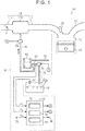
FIG. 1 is a schematic view of an internal combustion engine; -
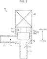
FIG. 2 is a schematic cross-sectional view of a sealing valve; -
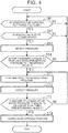
FIG. 3 is a flowchart showing an abnormality determination process; -
FIG. 4 is a flowchart showing a valve-opening position learning process; -
FIG. 5A is a time chart showing a state of the sealing valve in the abnormality determination process; -
FIG. 5B is a time chart showing changes in tank pressure in the abnormality determination process; and -
FIG. 5C is a time chart showing changes in vapor pressure in the abnormality determination process. - The embodiment of the invention will be described hereinafter with reference to
FIGS. 1 to 5C . First of all, the schematic configuration of aninternal combustion engine 100 to which the invention is applied will be described. Incidentally, in the following description, the simple mention of "upstream" and "downstream" means "upstream" and "downstream" in a direction in which intake air, exhaust gas, evaporative fuel, and outside air flow. - As shown in
FIG. 1 , theinternal combustion engine 100 is equipped with anintake passage 11 for introducing intake air from outside theinternal combustion engine 100. Athrottle valve 21 is arranged in anupstream intake passage 11a as part of theintake passage 11. Thethrottle valve 21 controls the amount of intake air flowing through a flow channel of theupstream intake passage 11a by opening/closing the flow channel of theupstream intake passage 11a. - A downstream side of the
upstream intake passage 11a is connected to asurge tank 11b for suppressing the pulsation of intake air and the like. A downstream side of thesurge tank 11b in theintake passage 11 is connected to adownstream intake passage 11c in theintake passage 11. - A downstream side of the
downstream intake passage 11c in theintake passage 11 is connected to acylinder 12 in which fuel is mixed with intake air and burned. Fuel is injected into thecylinder 12 by afuel injection valve 22. Besides, apiston 23 that moves in a reciprocating manner inside thecylinder 12 is arranged inside thecylinder 12. Anexhaust passage 13 for discharging exhaust gas from thecylinder 12 is connected to thecylinder 12. - The
internal combustion engine 100 is equipped with afuel tank 31 that stores fuel to be supplied to the aforementionedfuel injection valve 22. Although not shown in the drawing, a feed pump is accommodated in thefuel tank 31, and the fuel force-fed by the feed pump is supplied to thefuel injection valve 22 via a fuel pipeline. - An evaporative
fuel treatment apparatus 50 that restrains evaporative fuel produced in thefuel tank 31 from being discharged to the atmosphere is connected to thefuel tank 31. The evaporativefuel treatment apparatus 50 is equipped with acanister 52 that adsorbs evaporative fuel produced in thefuel tank 31. One end of avapor passage 51 that introduces evaporative fuel into thecanister 52 is connected to thecanister 52. The other end of thevapor passage 51 reaches the inside of thefuel tank 31. Asealing valve 70 that changes over a flow channel of thevapor passage 51 to one of its open state and its closed state is attached to a non-end portion of thevapor passage 51. - An outside
air introduction passage 53 that introduces outside air into thecanister 52 is connected to thecanister 52. Besides, apurge passage 55 that links thecanister 52 and thesurge tank 11b with each other is connected to thecanister 52. Apurge valve 65 that changes over a flow channel of thepurge passage 55 to one of its open state and its closed state is attached to a non-end portion of thepurge passage 55. - A tank
internal pressure sensor 91 that detects a tank pressure Pt as a pressure inside thefuel tank 31 is attached to thefuel tank 31. Besides, apressure sensor 92 that detects a vapor pressure Pv as a pressure in the flow channel of thevapor passage 51 is attached to a region of thevapor passage 51 located on thecanister 52 side with respect to thesealing valve 70. Incidentally, this tankinternal pressure sensor 91 and thispressure sensor 92 constitute part of the evaporativefuel treatment apparatus 50. - Next, the configuration of the
sealing valve 70 will be concretely described. As shown inFIG. 2 , thesealing valve 70 is equipped with avalve body 71 in which a valve element 75 is accommodated. Thevalve body 71 assumes the appearance of a circular cylinder as a whole, and aninternal space 71a capable of accommodating the valve element 75 is defined inside thevalve body 71. In the present embodiment, theinternal space 71a of thevalve body 71 substantially assumes the shape of a circular cylinder extending in an axial direction of the valve body 71 (a vertical direction inFIG. 2 ). - A
first connection portion 72 that substantially assumes the shape of a circular cylinder protrudes from one end surface (on a lower side inFIG. 2 ) of thevalve body 71, in the axial direction of thevalve body 71. A central axis of thefirst connection portion 72 is substantially coaxial with a central axis of thevalve body 71. Aninternal space 72a of thefirst connection portion 72 communicates with theinternal space 71a of thevalve body 71. Thefirst connection portion 72 has an inner diameter that is smaller than an inner diameter of thevalve body 71. A pipeline that defines thevapor passage 51 located on thefuel tank 31 side with respect to the sealingvalve 70 is connected to thefirst connection portion 72. - A
second connection portion 73 that substantially assumes the shape of a circular cylinder protrudes from an outer peripheral surface of thevalve body 71. Thesecond connection portion 73 is located at one end portion (on the lower side inFIG. 2 ) of thevalve body 71. Aninternal space 73a of thesecond connection portion 73 communicates with theinternal space 71a of thevalve body 71. Thesecond connection portion 73 has an inner diameter that is approximately equal to an inner diameter of thefirst connection portion 72. A pipeline that defines thevapor passage 51 located on thecanister 52 side with respect to the sealingvalve 70 is connected to thesecond connection portion 73. In the present embodiment, theinternal space 72a of thefirst connection portion 72, theinternal space 71a of thevalve body 71, and theinternal space 73a of thesecond connection portion 73 in the sealingvalve 70 constitute part of thevapor passage 51. - A
step motor 77 for driving the valve element 75 is fixed to the other end surface (on an upper side inFIG. 2 ) in the axial direction of thevalve body 71. By performing energization control of thestep motor 77 in accordance with a pulse-wave control signal, an output shaft of thestep motor 77 rotates by an angle corresponding to one step for each pulse. InFIG. 2 , the configuration of thestep motor 77 is depicted in a simplified manner. - A valve shaft 75b of the valve element 75 that opens/closes a flow channel of the
valve body 71 is coupled to the output shaft of thestep motor 77. The valve shaft 75b substantially assumes the shape of a rod. A valve portion 75a that substantially assumes the shape of a circular cylinder is fixed to a distal end (an end on the opposite side of the step motor 77) of the valve shaft 75b. The valve portion 75a is located in theinternal space 71a of thevalve body 71. The valve portion 75a has an outer diameter that is slightly smaller than the inner diameter of thevalve body 71 and that is larger than the inner diameter of thefirst connection portion 72. A central axis of the valve portion 75a is substantially coaxial with the central axis of thevalve body 71. A sealingmember 76 that substantially assumes the shape of a circular plate is fixed to one end surface (on the lower side inFIG. 2 ) of the valve portion 75a of the valve element 75. The sealingmember 76 has an outer diameter that is slightly smaller than the outer diameter of the valve portion 75a and that is larger than the inner diameter of thefirst connection portion 72. The sealingmember 76 is made of an elastically deformable material, which is fluoro rubber (FKM) in the present embodiment. - In the case where the sealing
valve 70 is in its closed state, the output shaft of thestep motor 77 rotates, and the valve element 75 consequently moves toward one side (on the lower side inFIG. 2 ) in the axial direction of thevalve body 71. Then, the sealingmember 76 elastically deforms while being sandwiched between an end surface of the valve element 75 and an inner surface of thevalve body 71. Thus, an opening on thefirst connection portion 72 side in theinternal space 71 a of thevalve body 71 is closed up, and the flow channel of thevalve body 71 is rendered in its closed state. - On the other hand, in the case where the sealing
valve 70 is in its open state, the output shaft of thestep motor 77 rotates, and the valve element 75 consequently moves toward the other side (on the upper side inFIG. 2 ) in the axial direction of thevalve body 71. Then, the sealingmember 76 separates from the inner surface of thevalve body 71. Thus, the opening on thefirst connection portion 72 side in theinternal space 71a of thevalve body 71 is opened, and the flow channel of thevalve body 71 is rendered in its open state. - As shown in
FIG. 1 , the above-mentionedpurge valve 65 and the above-mentionedsealing valve 70 are controlled to be opened/closed by anelectronic control unit 80. In this case, with a view to explaining the kinds of control performed by theelectronic control unit 80 for descriptive purposes, the respective kinds of control will be described, from a functional point of view, as being performed by avalve control unit 81, apressure detection unit 82, and adetermination unit 83. Theelectronic control unit 80 is equipped with thevalve control unit 81 for performing control to open or close thepurge valve 65 and the sealingvalve 70. Thevalve control unit 81 outputs, to thepurge valve 65, a control signal for performing control to open/close thepurge valve 65. When a request for a purge treatment for causing the evaporative fuel adsorbed inside thecanister 52 to flow through theintake passage 11 via thepurge passage 55 is made, thevalve control unit 81 controls thepurge valve 65 to its open state. Besides, thevalve control unit 81 outputs, to the sealingvalve 70, a control signal for performing control to open or close the sealingvalve 70. In concrete terms, thevalve control unit 81 outputs a pulse-wave control signal for driving the output shaft of thestep motor 77 in the sealingvalve 70 in a circumferential direction of the output shaft at a predetermined step number. Then, thestep motor 77 in the sealingvalve 70 is controlled, and the output shaft of thestep motor 77 rotates toward one or the other side in the circumferential direction of the output shaft, at a step number corresponding to the number of pulses of the control signal. Then, the valve element 75 in the sealingvalve 70 is moved, and the flow channel of thevalve body 71 assumes its open state or its closed state. - In the case where the absolute value of a difference between the tank pressure Pt and an atmospheric pressure Pa is low etc., the
valve control unit 81 controls the sealingvalve 70 to its closed state. Besides, in the case where thepurge valve 65 is in its open state, thevalve control unit 81 controls the sealingvalve 70 to its open state when the tank pressure Pt is significantly higher than the atmospheric pressure Pa or when the tank pressure Pt is significantly lower than the atmospheric pressure Pa. In the present embodiment, theelectronic control unit 80 is configured as an electronic control unit (an ECU) that is configured to control theinternal combustion engine 100 as a whole, that is, to control the opening degree of thethrottle valve 21, the fuel injection amount of thefuel injection valve 22, and the like, in addition to controlling the above-mentionedsealing valve 70 and the above-mentionedpurge valve 65. - The
electronic control unit 80 is equipped with thepressure detection unit 82 that detects pressures of the respective portions, and thedetermination unit 83 that determines whether or not there is an abnormality in the tankinternal pressure sensor 91. Thepressure detection unit 82 detects the tank pressure Pt based on a signal input from the tankinternal pressure sensor 91. Thepressure detection unit 82 detects the vapor pressure Pv based on a signal input from thepressure sensor 92. Thepressure detection unit 82 detects the atmospheric pressure Pa based on a signal input from anatmospheric pressure sensor 93 that detects a pressure of the atmosphere. Theatmospheric pressure sensor 93 is installed at a position exposed to no wind pressure resulting from the running of the vehicle, for example, in an engine room or the like of the vehicle. - The
determination unit 83 determines, based on the tank pressure Pt and the vapor pressure Pv that have been detected by thepressure detection unit 82, whether or not there is an abnormality in the tankinternal pressure sensor 91. Besides, a warninglamp 96 for notifying a driver or the like of an abnormality in the tankinternal pressure sensor 91 is electrically connected to theelectronic control unit 80. The warninglamp 96 lights up when a signal is output from theelectronic control unit 80. The warninglamp 96 is attached to, for example, an instrument panel inside the vehicle. - Next, an abnormality determination process that is performed by the
electronic control unit 80 to determine whether or not there is an abnormality in the tankinternal pressure sensor 91 will be described. Theelectronic control unit 80 performs the abnormality determination process every time a system activation switch (which may also be referred to as an ignition switch or a main switch) for the vehicle is operated to be turned on, namely, every time theelectronic control unit 80 starts operating. - As shown in
FIG. 3 , when the abnormality determination process is started, theelectronic control unit 80 performs the processing of step S11. In step S11, theelectronic control unit 80 determines whether or not a condition for carrying out purge is fulfilled. As the condition for carrying out purge, it is possible to mention that the engine rotational speed of theinternal combustion engine 100 is equal to or higher than a rotational speed at which the operation thereof can be continued in an autonomous manner (an idling rotational speed), that a fuel cut process for temporarily stopping the injection of fuel from thefuel injection valve 22 is not being performed at the time of deceleration or the like of the vehicle, and the like. When it is determined in step S11 that the condition for carrying out purge is not fulfilled (NO in S11), theelectronic control unit 80 repeatedly performs the processing of step S11. On the other hand, when it is determined in step S11 that the condition for carrying out purge is fulfilled (YES in S11), theelectronic control unit 80 advances the process to step S12. - In step S12, the
electronic control unit 80 determines whether or not the sealingvalve 70 is in its closed state. When it is determined in step S12 that the sealingvalve 70 is not in its closed state (NO in S12), theelectronic control unit 80 returns the process to step S11. On the other hand, when it is determined in step S12 that the sealingvalve 70 is in its closed state (YES in S12), theelectronic control unit 80 advances the process to step S13. - In step S13, the
pressure detection unit 82 in theelectronic control unit 80 detects and stores the tank pressure Pt, the vapor pressure Pv, and the atmospheric pressure Pa. After that, theelectronic control unit 80 advances the process to step S21. - In step S21, the
electronic control unit 80 determines whether or not the tank pressure Pt stored in step S13 is higher than the atmospheric pressure Pa. If it is determined in step S21 that the tank pressure Pt is higher than the atmospheric pressure Pa (YES in S21), theelectronic control unit 80 advances the process to step S22. - In step S22, the
valve control unit 81 in theelectronic control unit 80 performs control in such a manner as to change over the sealingvalve 70 from its closed state to its open state. In concrete terms, thevalve control unit 81 outputs, to thestep motor 77, a control signal whose number of pulses corresponds to a step number for changing over the sealingvalve 70 from its closed state to its open state, and rotates the output shaft of thestep motor 77 in such a manner as to move the valve element 75 toward its open side. Thestep motor 77 is changed over between its energized state and its non-energized state through pulse width modulation (PWM) control. In the present embodiment, the energization duty ratio as a ratio of a time of the energized state to a time of one cycle (one pulse cycle) on which thestep motor 77 is changed over between its energized state and its non-energized state is set equal to about 50%. After that, theelectronic control unit 80 advances the process to step S24. - On the other hand, when it is determined in step S21 that the tank pressure Pt is equal to or lower than the atmospheric pressure Pa (NO in S21), the
electronic control unit 80 advances the process to step S23. In step S23, thevalve control unit 81 in theelectronic control unit 80 performs control in such a manner as to change over the sealingvalve 70 from its closed state to its open state. In concrete terms, thevalve control unit 81 outputs, to thestep motor 77, a control signal whose number of pulses corresponds to the step number for changing over the sealingvalve 70 from its closed state to its open state, and rotates the output shaft of thestep motor 77 in such a manner as to move the valve element 75 toward its open side. In the present embodiment, when the sealingvalve 70 is changed over from its closed state to its open state in step S23, the energization duty ratio is set equal to 100%, unlike the case of the above-mentioned step S22. That is, in the processing of step S23, the speed at which the valve element 75 of the sealingvalve 70 is opened in changing over the sealingvalve 70 from its closed state to its open state is set higher in the processing of step S23 than in the processing of step S22. After that, theelectronic control unit 80 advances the process to step S24. - In step S24, the
pressure detection unit 82 in theelectronic control unit 80 detects and stores the tank pressure Pt, the vapor pressure Pv, and the atmospheric pressure Pa again. After that, theelectronic control unit 80 advances the process to step S31. - In step S31, the
determination unit 83 in theelectronic control unit 80 determines whether or not an amount of change ΔPt in the tank pressure Pt in changing over the sealingvalve 70 from its closed state to its open state is lower than a first predetermined value A set in advance. In concrete terms, thedetermination unit 83 defines the amount of change ΔPt as an absolute value of a difference between the tank pressure Pt detected in step S13 with the sealingvalve 70 in its closed state and the tank pressure Pt detected in step S24 with the sealingvalve 70 in its open state, and determines whether or not this value is lower than the first predetermined value A. It should be noted herein that even when the pressure inside thefuel tank 31 is constant as a whole, the detection value of the tankinternal pressure sensor 91 may slightly fluctuate due to local fluctuations in pressure resulting from the swinging of the fuel in thefuel tank 31, and the detection value of the tankinternal pressure sensor 91 may slightly fluctuate due to external noise. In view of this, a value larger than an amount of slight fluctuations as mentioned above is set in advance as the first predetermined value A. When it is determined in step S31 that the amount of change ΔPt in the tank pressure Pt in changing over the sealingvalve 70 from its closed state to its open state is lower than the first predetermined value A (YES in S31), theelectronic control unit 80 advances the process to step S32. - In step S32, the
determination unit 83 in theelectronic control unit 80 determines whether or not an amount of change ΔPv in the vapor pressure Pv in changing over the sealingvalve 70 from its closed state to its open state is equal to or higher than a second predetermined value B set in advance. In concrete terms, thedetermination unit 83 defines the amount of change ΔPv as an absolute value of a difference between the vapor pressure Pv detected in step S13 with the sealingvalve 70 in its closed state and the vapor pressure Pv detected in step S24 with the sealingvalve 70 in its open state, and determines whether or not this value is equal to or higher than the second predetermined value B. It should be noted herein that even when the pressure in thevapor passage 51 located on thecanister 52 side with respect to the sealingvalve 70 is constant as a whole, the detection value of thepressure sensor 92 may slightly fluctuate, as is the case with the above-mentioned tankinternal pressure sensor 91. A value larger than an amount of such slight fluctuations is set in advance as the second predetermined value B. When it is determined in step S32 that the amount of change ΔPv in the vapor pressure Pv in changing over the sealingvalve 70 from its closed state to its open state is equal to or higher than the second predetermined value B set in advance (YES in S32), theelectronic control unit 80 advances the process to step S41. - In step S41, the
determination unit 83 in theelectronic control unit 80 determines that the tankinternal pressure sensor 91 is abnormal. Thevalve control unit 81 in theelectronic control unit 80 performs control in such a manner as to change over the sealingvalve 70 from its open state to its closed state. After that, theelectronic control unit 80 advances the process to step S42. In step S42, thedetermination unit 83 in theelectronic control unit 80 outputs a signal to the warninglamp 96 to light up the warninglamp 96. Incidentally, after it is determined in step S41 that the tankinternal pressure sensor 91 is abnormal, the warninglamp 96 remains lit up during the operation of theelectronic control unit 80, until it is determined in later-described step S51 that the tankinternal pressure sensor 91 is normal. After that, theelectronic control unit 80 ends the abnormality determination process. - On the other hand, when it is determined in step S31 that the amount of change ΔPt in the tank pressure Pt in changing over the sealing
valve 70 from its closed state to its open state is not lower than the first predetermined value A set in advance (NO in S31), theelectronic control unit 80 advances the process to step S51. Besides, when it is determined in step S32 that the amount of change ΔPv in the vapor pressure Pv in changing over the sealingvalve 70 from its closed state to its open state is not equal to or higher than the second predetermined value B set in advance (NO in S32), theelectronic control unit 80 advances the process to step S51. - In step S51, the
determination unit 83 in theelectronic control unit 80 determines that the tankinternal pressure sensor 91 is normal. Besides, thevalve control unit 81 in theelectronic control unit 80 performs control in such a manner as to change over the sealingvalve 70 from its open state to its closed state. Incidentally, when the warninglamp 96 is lit up at the time point of step S51, the warninglamp 96 is turned off. After that, theelectronic control unit 80 ends the abnormality determination process. - Next, a valve-opening position learning process that is performed by the
electronic control unit 80 to learn a valve-opening position of the sealingvalve 70 will be described. Theelectronic control unit 80 performs the valve-opening position learning process when it is determined in the abnormality determination process that the tankinternal pressure sensor 91 is normal. - As shown in
FIG. 4 , when the valve-opening position learning process is started, theelectronic control unit 80 performs the processing of step S61. In step S61, theelectronic control unit 80 determines whether or not the condition for carrying out purge is fulfilled. In this embodiment, the condition for carrying out purge in step S61 is the same as the condition for carrying out purge in step S11 in the above-mentioned abnormality determination process. When it is determined in step S61 that the condition for carrying out purge is not fulfilled (NO in S61), theelectronic control unit 80 repeatedly performs the processing of step S61. On the other hand, when it is determined in step S61 that the condition for carrying out purge is fulfilled (YES in S61), theelectronic control unit 80 advances the process to step S62. - In step S62, the
electronic control unit 80 determines whether or not the sealingvalve 70 is in its closed state. When it is determined in step S62 that the sealingvalve 70 is not in its closed state (NO in S62), theelectronic control unit 80 returns the process to step S61. On the other hand, when it is determined in step S62 that the sealingvalve 70 is in its closed state (YES in S62), theelectronic control unit 80 advances the process to step S63. - In step S63, the
pressure detection unit 82 in theelectronic control unit 80 detects and stores the tank pressure Pt, the vapor pressure Pv, and the atmospheric pressure Pa. After that, theelectronic control unit 80 advances the process to step S64. - In step S64, the
electronic control unit 80 determines whether or not the tank pressure Pt stored in step S63 is higher than the atmospheric pressure Pa by a reference value X or more. It should be noted herein that the reference value X is determined as a value at which the pressure in thevapor passage 51 downstream of the sealingvalve 70 can fluctuate as a result of the flow of evaporative fuel through thevapor passage 51 even in the case where the sealingvalve 70 has slightly opened, and that the reference value X is determined as about several % of the atmospheric pressure Pa. When it is determined in step S64 that the tank pressure Pt is not higher than the atmospheric pressure Pa by the reference value X or more (NO in S64), theelectronic control unit 80 returns the process to step S61. On the other hand, when it is determined in step S64 that the tank pressure Pt is higher than the atmospheric pressure Pa by the reference value X or more (YES in S64), theelectronic control unit 80 advances the process to step S71. - In step S71, the
valve control unit 81 in theelectronic control unit 80 performs a valve opening/closing process for driving thestep motor 77 in such a manner as to move the valve element 75 in the sealingvalve 70 toward its open side. In concrete terms, thevalve control unit 81 outputs, to thestep motor 77, a control signal whose number of pulses corresponds to a predetermined step number set in advance, and rotates the output shaft of thestep motor 77 at the predetermined step number in such a manner as to move the valve element 75 toward its open side. In the present embodiment, the predetermined step number in the valve opening/closing process is set equal to one step. After that, theelectronic control unit 80 advances the process to step S72. - In step S72, the
pressure detection unit 82 in theelectronic control unit 80 detects and stores the tank pressure Pt, the vapor pressure Pv, and the atmospheric pressure Pa again. After that, theelectronic control unit 80 advances the process to step S73. - In step S73, the
determination unit 83 in theelectronic control unit 80 determines whether or not the amount of change ΔPv in the vapor pressure Pv in changing over the sealingvalve 70 from its closed state to its open state is equal to or higher than a third predetermined value C set in advance. In concrete terms, thedetermination unit 83 defines the amount of change ΔPv as an absolute value of a difference between the vapor pressure Pv detected in step S63 with the sealingvalve 70 in its closed state and the vapor pressure Pv detected in step S72 immediately preceding step S73 with the sealingvalve 70 in its open state, and determines whether or not this value is equal to or higher than the third predetermined value C. It should be noted herein that an amount of change by which the pressure in thevapor passage 51 downstream of the sealingvalve 70 can fluctuate as soon as the sealingvalve 70 changes over from its closed state to its open state is obtained through an experiment or the like in the case where the tank pressure Pt is higher than the atmospheric pressure Pa by the reference value X or more, and that a value lower than the amount of change in pressure is set in advance as the third predetermined value C. When it is determined in step S73 that the amount of change ΔPv in the vapor pressure Pv in changing over the sealingvalve 70 from its closed state to its open state is not equal to or higher than the third predetermined value C set in advance (NO in S73), theelectronic control unit 80 returns the process to step S71. - On the other hand, when it is determined in step S73 that the amount of change ΔPv in the vapor pressure Pv in changing over the sealing
valve 70 from its closed state to its open state is equal to or higher than the third predetermined value C set in advance (YES in S73), theelectronic control unit 80 advances the process to step S74. - In step S74, the
determination unit 83 in theelectronic control unit 80 learns the position of the valve element 75 at the time when it is determined in the valve opening/closing process that the amount of change ΔP in the vapor pressure Pv is equal to or higher than the third predetermined value C set in advance, as the valve-opening position of the sealingvalve 70. Besides, thevalve control unit 81 in theelectronic control unit 80 performs control in such a manner as to change over the sealingvalve 70 from its open state to its closed state. After that, theelectronic control unit 80 ends the valve-opening position learning process. - The operation of the present embodiment will be described. In the
internal combustion engine 100, in the case where the purge treatment for causing evaporative fuel to flow from thecanister 52 side to theintake passage 11 side is not carried out, thepurge valve 65 is controlled to its closed state. Then, when the sealingvalve 70 is controlled to its open state, gas flows through thevapor passage 51. It should be noted herein that when the tank pressure Pt is higher than the atmospheric pressure Pa, the evaporative fuel produced in thefuel tank 31 flows into thecanister 52 via thevapor passage 51. Then, the evaporative fuel that has flowed into thecanister 52 is adsorbed into thecanister 52. In this case, the tank pressure Pt changes in such a manner as to gradually fall and approach the atmospheric pressure Pa. On the other hand, when the tank pressure Pt is lower than the atmospheric pressure Pa, outside air flows into thefuel tank 31 via the outsideair introduction passage 53, thecanister 52, and thevapor passage 51. In this case, the tank pressure Pt changes in such a manner as to gradually rise and approach the atmospheric pressure Pa. - In the
internal combustion engine 100, in the case where the purge treatment for causing evaporative fuel to flow from thecanister 52 side to theintake passage 11 side is carried out, thepurge valve 65 is controlled to its open state. Then, outside air flows into thecanister 52 via the outsideair introduction passage 53, due to a negative pressure in a region of theintake passage 11 located downstream of thethrottle valve 21. Then, the evaporative fuel adsorbed in thecanister 52 and outside air flow into the region of theintake passage 11 located downstream of thethrottle valve 21, via thepurge passage 55. - When the sealing
valve 70 is controlled to its open state in the case where the purge treatment is thus carried out, gas flows through thevapor passage 51. It should be noted herein that when the tank pressure Pt is higher than the atmospheric pressure Pa, the evaporative fuel produced in thefuel tank 31 flows into thecanister 52 via thevapor passage 51. Then, the evaporative fuel that has flowed into thecanister 52 and outside air flow into the region of theintake passage 11 located downstream of thethrottle valve 21, via thepurge passage 55. In this case, the tank pressure Pt changes in such a manner as to gradually fall and approach the atmospheric pressure Pa. On the other hand, in the case where the tank pressure Pt is lower than the atmospheric pressure Pa, outside air flows into thefuel tank 31 via the outsideair introduction passage 53, thecanister 52, and thevapor passage 51. In this case, the tank pressure Pt changes in such a manner as to gradually rise and approach the atmospheric pressure Pa. - It is assumed herein that there is an abnormality in the tank
internal pressure sensor 91 with the detection value of the tankinternal pressure sensor 91 being held equal to a constant value that is approximately equal to the atmospheric pressure Pa at and after a timing t0, as indicated by an alternate long and two short dashes line inFIG. 5B . Besides, as indicated by a solid line inFIG. 5B , the actual tank pressure Pt is assumed to be higher than the atmospheric pressure Pa at the timing t0. Furthermore, it is assumed that the abnormality determination process is performed by performing operation to turn on the system activation switch for the vehicle, at the timing t0. - As shown in
FIG. 5A , when the condition for carrying out purge is fulfilled at a timing t1, the sealingvalve 70 is changed over from its closed state to its open state. Then, as indicated by the solid line inFIG. 5B , the actual tank pressure Pt changes in such a manner as to gradually fall, from the timing t1 to a timing t2. However, as indicated by the alternate long and two short dashes line inFIG. 5B , there is an abnormality in the tankinternal pressure sensor 91, so the detection value of the tankinternal pressure sensor 91 does not change from the timing t1 to the timing t2 either. Therefore, thedetermination unit 83 determines that the amount of change ΔPt in the tank pressure Pt in changing over the sealingvalve 70 from its closed state to its open state is lower than the first predetermined value A. On the other hand, as shown inFIG. 5C , the detection value of thepressure sensor 92 changes as the sealingvalve 70 is changed over from its closed state to its open state at the timing t1. Therefore, thedetermination unit 83 determines that the amount of change ΔPv in the vapor pressure Pv in changing over the sealingvalve 70 from its closed state to its open state is equal to or higher than the second predetermined value B. Then, thedetermination unit 83 determines that the tankinternal pressure sensor 91 is abnormal. Then, thedetermination unit 83 outputs a signal to the warninglamp 96 to light up the warninglamp 96. After that, as shown inFIG. 5A , the sealingvalve 70 is changed over from its open state to its closed state at the timing t2. - The effect of the present embodiment will be described. In the present embodiment, when the sealing
valve 70 is changed over from its closed state to its open state, gas flows through thevapor passage 51, thecanister 52, and the outsideair introduction passage 53, and the tank pressure Pt changes in such a manner as to approach the atmospheric pressure Pa. Therefore, in the case where the tankinternal pressure sensor 91 is normal, the tank pressure Pt detected by the tankinternal pressure sensor 91 changes. On the other hand, in the case where there is an abnormality in the tankinternal pressure sensor 91 with the detection value of the tankinternal pressure sensor 91 being held equal to the constant value, the tank pressure Pt detected by the tankinternal pressure sensor 91 does not change. - It should be noted herein that it is conceivable to determine that there is an abnormality in the tank
internal pressure sensor 91, for example, when the tank pressure Pt detected by the tankinternal pressure sensor 91 is held within a certain range from an upper limit of the tankinternal pressure sensor 91 or within a certain range from a lower limit of the tankinternal pressure sensor 91. Then, this configuration can also cope with an abnormality with the tankinternal pressure sensor 91 keeping detecting an intermediate value located apart from the upper limit or the lower limit to a certain extent instead of a value close to the upper limit or the lower limit, by setting the aforementioned certain range large. However, when the aforementioned certain range is set excessively large, it is likely to be erroneously determined that there is an abnormality in the tankinternal pressure sensor 91 even in the case where the tankinternal pressure sensor 91 is normal. - In the present embodiment, it is determined whether or not there is an abnormality in the tank
internal pressure sensor 91, based on the change in the vapor pressure Pv detected by thepressure sensor 92 as well as the amount of change ΔPt in the tank pressure Pt detected by the tankinternal pressure sensor 91. As described above, when the sealingvalve 70 is changed over from its closed state to its open state, the tank pressure Pt changes in such a manner as to approach the atmospheric pressure Pa, and as a result, the vapor pressure Pv also changes. This change in the vapor pressure Pv is caused even if there is an abnormality in the tankinternal pressure sensor 91. Accordingly, in the present embodiment, even when there is an abnormality in the tankinternal pressure sensor 91 with the tank pressure Pt detected by the tankinternal pressure sensor 91 being held equal to the constant value, the abnormality in the tankinternal pressure sensor 91 can be determined based on the change in the vapor pressure Pv detected by thepressure sensor 92. - It is assumed herein that it is determined that there is an abnormality in the tank
internal pressure sensor 91 on the ground that the detection value of thepressure sensor 92 has very slightly changed. In this case, it may be erroneously determined that the tankinternal pressure sensor 91 is abnormal, although the tankinternal pressure sensor 91 is normal. In the present embodiment, it is determined that there is an abnormality in the tankinternal pressure sensor 91, when the amount of change ΔPv in the vapor pressure Pv detected by thepressure sensor 92 is equal to or higher than the second predetermined value B. Therefore, in the present embodiment, it can be restrained from being erroneously determined that there is an abnormality in the tankinternal pressure sensor 91 on the ground that the amount of change ΔPv in the vapor pressure Pv detected by thepressure sensor 92 has changed by a slight amount that does not reflect whether the tankinternal pressure sensor 91 is normal or abnormal. - By the way, in the present embodiment, when the sealing
valve 70 is changed over from its closed state to its open state in the case where the tank pressure Pt is higher than the atmospheric pressure Pa, an excessively large amount of evaporative fuel may flow into thecanister 52 within a short period of time. When an excessively large amount of evaporative fuel flows into thecanister 52 within a short period of time, a large amount of evaporative fuel is adsorbed by thecanister 52, and thecanister 52 may become unable to adsorb evaporative fuel afterward in case of necessity. In the present embodiment, the speed at which the sealingvalve 70 is changed over from its closed state to its open state is set lower when the tank pressure Pt is higher than the atmospheric pressure Pa than when the tank pressure Pt is lower than the atmospheric pressure Pa in the case where the sealingvalve 70 is in its closed state. Therefore, in the present embodiment, the flow rate of gas flowing through thevapor passage 51 becomes relatively low during a transient period in which the sealingvalve 70 is being changed over from its closed state to its open state. Accordingly, an excessively large amount of evaporative fuel can be restrained from flowing into thecanister 52 from thefuel tank 31 via thevapor passage 51 within a short period of time. - In the aforementioned embodiment, with a view to appropriately adjusting the amount of evaporative fuel flowing through the
vapor passage 51, the position of the valve element 75 at the moment when the sealingvalve 70 changes over from its closed state to its open state needs to be accurately grasped as the valve-opening position of the sealingvalve 70. It should be noted herein that, for example, a configuration for learning the position of the valve element 75 when the sealingvalve 70 changes over from its closed state to its open state based on the amount of change ΔPt in the tank pressure Pt in the valve opening/closing process is conceivable, instead of the processing of step S73 in the valve-opening position learning process, as the configuration for learning the valve-opening position of the sealingvalve 70. However, thefuel tank 31 generally has a relatively large capacity, so the amount of change ΔPt in the tank pressure Pt tends to be low even when gas flows through thevapor passage 51 after the sealingvalve 70 changes over from its closed state to its open state. Therefore, if the valve-opening position learning process is based on the amount of change ΔPt in the tank pressure Pt, it may be impossible to appropriately detect the position of the valve element 75 when the sealingvalve 70 changes over from its closed state to its open state. - In the present embodiment, the position of the valve element 75 at the time when the amount of change ΔPv in the vapor pressure Pv in performing the valve opening/closing process becomes equal to or higher than the third predetermined value C set in advance is learned as the valve-opening position of the sealing
valve 70. The capacity in thevapor passage 51 is significantly smaller than the capacity of thefuel tank 31, so the change in the vapor pressure Pv in performing the valve opening/closing process is remarkable. Therefore, in the present embodiment, the valve-opening position of the sealingvalve 70 can be more accurately learned than in the configuration for learning the valve-opening position of the sealingvalve 70 based on the amount of change ΔPt in the tank pressure Pt. - The present embodiment can be carried out after being modified as follows. The present embodiment and the following modification examples can be combined with one another and carried out within such a range that there is no technical contradiction. In the aforementioned embodiment, the configuration for connecting the
purge passage 55 to theintake passage 11 can be appropriately changed. For example, in the case where a compressor of a turbocharger is attached to theintake passage 11, thepurge passage 55 may be connected to regions of theintake passage 11 located upstream and downstream of the compressor. - In the aforementioned embodiment, the processing of step S32 can be changed. For example, in step S32, it may be determined that the vapor pressure Pv has changed as a result of the changeover of the sealing
valve 70, when the speed at which the vapor pressure Pv in changing over the sealingvalve 70 from its closed state to its open state changes exceeds a certain speed. - In the aforementioned embodiment, the valve-opening speed of the valve element 75 of the sealing
valve 70 in steps S22 and S23 can be changed. For example, the valve-opening speed (the energization duty ratio) of the sealingvalve 70 may remain unchanged regardless of whether the tank pressure Pt is higher than the atmospheric pressure Pa or equal to or lower than the atmospheric pressure Pa. For example, in the case where a large amount of evaporative fuel can be adsorbed by thecanister 52 for the capacity of thefuel tank 31, there is no problem in particular even when a large amount of evaporative fuel flows into thecanister 52 as a result of the changeover of the sealingvalve 70 to its open state. - In the aforementioned embodiment, the predetermined step number in step S71 in the valve opening/closing process can be appropriately changed. For example, the predetermined step number in the valve opening/closing process may be set equal to or larger than 2 steps. It should be noted, however, that the predetermined step number in the valve opening/closing process is preferably set small from the standpoint of enhancing the learning accuracy of the valve-opening position learning process.
- In the aforementioned embodiment, the processing of step S73 can be changed. For example, in the case where the
fuel tank 31 has a relatively small capacity, it may be determined in step S73 whether or not the amount of change ΔPt in the tank pressure Pt in changing over the sealingvalve 70 from its closed state to its open state is equal to or higher than the third predetermined value C set in advance. - In the aforementioned embodiment, the timing for performing the abnormality determination process can be changed. For example, while the
electronic control unit 80 is in operation, the abnormality determination process may be repeatedly performed on a predetermined cycle (e.g., at intervals of several to several tens of minutes). Besides, the abnormality determination process can also be performed, for example, when the vehicle is parked etc. - In the aforementioned embodiment, the timing for performing the valve-opening position learning process can be changed. For example, while the
electronic control unit 80 is in operation after it is determined in the abnormality determination process that the tankinternal pressure sensor 91 is normal, the valve-opening position learning process may be repeatedly performed on a predetermined cycle (e.g., at intervals of several to several tens of minutes). - Besides, the valve-opening position learning process may be performed, for example, in step S22 in the abnormality determination process. In concrete terms, the processing of steps S71 to S74 may be incorporated into the processing of step S22, and the position of the valve element 75 at the time when it is determined that the amount of change ΔPv in the vapor pressure Pv is equal to or higher than the third predetermined value C set in advance may be learned as the valve-opening position of the sealing
valve 70 in step S22. - In the aforementioned embodiment, the configuration of the sealing
valve 70 can be changed. For example, a sealingmember 76 may be fixed to the inner surface of thevalve body 71 instead of or in addition to the sealingmember 76 fixed to the valve element 75. In concrete terms, anannular sealing member 76 may be fixed along an opening edge of thevalve body 71 on thefirst connection portion 72 side. In this case, the sealingmember 76 fixed to thevalve body 71 elastically deforms while being sandwiched between the end surface of the valve element 75 and the inner surface of thevalve body 71 when the sealingvalve 70 is in its closed state. - Besides, the material of the sealing
member 76 can be appropriately changed as long as it is an elastically deformable material. For example, the material of the sealingmember 76 may be replaced by a rubber material other than fluoro rubber (FKM) or a resin material. - In the aforementioned embodiment, the attachment position of the
pressure sensor 92 can be changed. For example, a pressure sensor may be attached to thecanister 52 instead of or in addition to thepressure sensor 92 attached to thevapor passage 51. In concrete terms, a pump module used to diagnose leakage in thecanister 52 is attached to thecanister 52 in some cases. Furthermore, as a rule, a pressure sensor for detecting the pressure inside thecanister 52, an air pump for reducing the pressure inside thecanister 52, and the like are built in this type of pump module. In the case where such a pump module is adopted, the pressure in thecanister 52 may be detected by the pressure sensor in the pump module, and the detected pressure may be regarded as a pressure in the flow channel of thevapor passage 51. - In the aforementioned embodiment, the valve-opening position learning process may be omitted. For example, in the case where a position sensor that detects the position of the valve element 75 is provided inside the sealing
valve 70, the valve-opening position of the sealingvalve 70 can be detected even when the above-mentioned valve-opening position learning process is omitted. Besides, when accurate control is not required in opening/closing the sealingvalve 70, the valve-opening position learning process and the configuration for detecting the valve-opening position can be omitted. - In the evaporative fuel treatment apparatus of Japanese Patent Application Publication No.
2016-079851 JP 2016-079851 A - A technical concept that can be grasped from the aforementioned embodiment and the modification examples will be described. An evaporative fuel treatment apparatus is equipped with a canister that adsorbs evaporative fuel, a vapor passage that is connected to the canister and that introduces evaporative fuel produced in a fuel tank into the canister, an outside air introduction passage that is connected to the canister and that introduces outside air into the canister, a purge passage that connects the canister and an intake passage to each other, a sealing valve that is provided in the vapor passage and that opens/closes a flow channel of the vapor passage, and a tank internal pressure sensor that detects a tank pressure as a pressure inside the fuel tank. The evaporative fuel treatment apparatus is characterized as follows. The sealing valve is equipped with a valve body that defines part of the vapor passage, a valve element that is provided inside the valve body and that opens/closes a flow channel of the valve body, a sealing member that is fixed to at least one of the valve body and the valve element and that elastically deforms while being sandwiched between the valve body and the valve element when the flow channel of the valve body is rendered in its closed state, and a step motor that moves the valve element. The evaporative fuel treatment apparatus is further equipped with a pressure sensor that is provided in at least one of the canister and a region of the vapor passage located on a canister side with respect to the sealing valve and that detects a vapor pressure as a pressure in the flow channel of the vapor passage, a pressure detection unit that detects the tank pressure based on a signal input from the tank internal pressure sensor and that detects the vapor pressure based on a signal input from the pressure sensor, a determination unit that learns a valve-opening position of the sealing valve, and a valve control unit that performs control to open or close the sealing valve. The valve control unit performs a valve opening/closing process for driving the step motor each time by a predetermined step number in changing over the sealing valve from its closed state to its open state. The determination unit learns, as the valve-opening position of the sealing valve, a position of the valve element at a time when an amount of change in the vapor pressure in performing the valve opening/closing process becomes equal to or higher than a third predetermined value set in advance.
Claims (5)
- An evaporative fuel treatment apparatus (50) comprising:a canister (52) that adsorbs evaporative fuel;a vapor passage (51) that is connected to the canister (52) and that introduces evaporative fuel produced in a fuel tank (31) into the canister (52);an outside air introduction passage (53) that is connected to the canister (52) and that introduces outside air into the canister (52);a purge passage (55) that connects the canister (52) and an intake passage (11) to each other;a sealing valve (70) that is provided in the vapor passage (51) and that is configured to open or close a flow channel of the vapor passage (51);a tank internal pressure sensor (91) configured to detect a tank pressure as a pressure inside the fuel tank (31);a pressure sensor (92) that is provided in at least one of the canister (52) and a region of the vapor passage (51) located on a canister side with respect to the sealing valve (70), the pressure sensor (92) being configured to detect a vapor pressure as a pressure in the flow channel of the vapor passage (51); andan electronic control unit (80) configured todetect the tank pressure based on a signal input from the tank internal pressure sensor (91),detect the vapor pressure based on a signal input from the pressure sensor (92), andperform control to open or close the sealing valve (70),characterized by the electronic control unit (80) being further configured to determine whether or not there is an abnormality in the tank internal pressure sensor (91), based on a change in the vapor pressure in changing over the sealing valve (70) from a closed state to an open state, when the electronic control unit (80) determines that an amount of change in the tank pressure in changing over the sealing valve (70) from the closed state to the open state is lower than a first predetermined value set in advance.
- The evaporative fuel treatment apparatus (50) according to claim 1, characterized in that the electronic control unit (80) is configured to determine that the tank internal pressure sensor (91) is abnormal when the amount of change in the vapor pressure in changing over the sealing valve (70) from the closed state to the open state is equal to or higher than a second predetermined value set in advance.
- The evaporative fuel treatment apparatus (50) according to claim 1 or 2, characterized in that the electronic control unit (80) is configured to make a valve-opening speed in changing over the sealing valve (70) from the closed state to the open state lower when the tank pressure with the sealing valve (70) in the closed state is higher than an atmospheric pressure than when the tank pressure with the sealing valve (70) in the closed state is lower than the atmospheric pressure.
- The evaporative fuel treatment apparatus (50) according to any one of claims 1 to 3, characterized in that
the sealing valve (70) includes a valve body (71), a valve element (75), a sealing member (76), and a step motor (77),
the valve body (71) defines part of the vapor passage (51),
the valve element (75) is provided inside the valve body (71), and is configured to open or close a flow channel of the valve body (71),
the sealing member (76) is fixed to at least one of the valve body (71) and the valve element (75), and elastically deforms while being sandwiched between the valve body (71) and the valve element (75) when the flow channel of the valve body (71) is in a closed state,
the step motor (77) is configured to move the valve element (75),
the electronic control unit (80) is configured to perform a valve opening or closing process for driving the step motor (77) each time by a predetermined step number, in changing over the sealing valve (70) from the closed state to the open state, and
the electronic control unit (80) is configured to learn a position of the valve element (75) at a time when an amount of change in the vapor pressure in performing the valve opening/closing process becomes equal to or higher than a third predetermined value set in advance, as a valve-opening position of the sealing valve (70). - A control method for an evaporative fuel treatment apparatus (50), the evaporative fuel treatment apparatus (50) including a canister (52) that adsorbs evaporative fuel, a vapor passage (51) that is connected to the canister (52), an outside air introduction passage (53) that is connected to the canister (52), a purge passage (55), a sealing valve (70) that is provided in the vapor passage (51), a tank internal pressure sensor (91), a pressure sensor (92), and an electronic control unit (80), the vapor passage (51) that introduces evaporative fuel produced in a fuel tank (31) into the canister (52), the outside air introduction passage (53) that introduces outside air into the canister (52), the purge passage (55) that connects the canister (52) and an intake passage (11) to each other, the sealing valve (70) being configured to open or close a flow channel of the vapor passage (51), the tank internal pressure sensor (91) being configured to detect a tank pressure as a pressure inside the fuel tank (31), the pressure sensor (92) being provided in at least one of the canister (52) and a region of the vapor passage (51) located on a canister side with respect to the sealing valve (70), and the pressure sensor (92) being configured to detect a vapor pressure as a pressure in the flow channel of the vapor passage (51),
the control method comprising:detecting, by the electronic control unit (80), the tank pressure based on a signal input from the tank internal pressure sensor (91);detecting, by the electronic control unit (80), the vapor pressure based on a signal input from the pressure sensor (92); andperforming, by the electronic control unit (80), control to open or close the sealing valve (70);characterized in that the control method further comprises determining, by the electronic control unit (80), whether or not there is an abnormality in the tank internal pressure sensor (91), based on a change in the vapor pressure in changing over the sealing valve (70) from a closed state to an open state, when the electronic control unit (80) determines that an amount of change in the tank pressure in changing over the sealing valve (70) from the closed state to the open state is lower than a first predetermined value set in advance.
Applications Claiming Priority (1)
| Application Number | Priority Date | Filing Date | Title |
|---|---|---|---|
| JP2018103803A JP2019206959A (en) | 2018-05-30 | 2018-05-30 | Fuel evaporation processing apparatus |
Publications (2)
| Publication Number | Publication Date |
|---|---|
| EP3575586A1 EP3575586A1 (en) | 2019-12-04 |
| EP3575586B1 true EP3575586B1 (en) | 2020-11-25 |
Family
ID=66647159
Family Applications (1)
| Application Number | Title | Priority Date | Filing Date |
|---|---|---|---|
| EP19176268.1A Not-in-force EP3575586B1 (en) | 2018-05-30 | 2019-05-23 | Evaporative fuel treatment apparatus and control method for evaporative fuel treatment apparatus |
Country Status (4)
| Country | Link |
|---|---|
| US (1) | US10718281B2 (en) |
| EP (1) | EP3575586B1 (en) |
| JP (1) | JP2019206959A (en) |
| CN (1) | CN110552818B (en) |
Families Citing this family (2)
| Publication number | Priority date | Publication date | Assignee | Title |
|---|---|---|---|---|
| JP7467387B2 (en) * | 2021-06-02 | 2024-04-15 | 愛三工業株式会社 | Leak diagnosis device for fuel vapor processing system |
| JP7763733B2 (en) | 2022-09-08 | 2025-11-04 | 愛三工業株式会社 | Valve System |
Family Cites Families (15)
| Publication number | Priority date | Publication date | Assignee | Title |
|---|---|---|---|---|
| US5726354A (en) * | 1995-07-31 | 1998-03-10 | Toyota Jidosha Kabushiki Kaisha | Testing method for fuel vapor treating apparatus |
| JP3729683B2 (en) * | 1998-12-04 | 2005-12-21 | トヨタ自動車株式会社 | Evaporative purge system failure diagnosis device |
| JP2002371924A (en) * | 2001-06-15 | 2002-12-26 | Mitsubishi Electric Corp | Failure diagnosis device for evaporation purge system |
| JP5761515B2 (en) * | 2011-10-27 | 2015-08-12 | 三菱自動車工業株式会社 | Fuel evaporative emission control device |
| JP5936985B2 (en) * | 2012-10-12 | 2016-06-22 | 愛三工業株式会社 | Evaporative fuel processing equipment |
| JP5950279B2 (en) * | 2012-10-30 | 2016-07-13 | 本田技研工業株式会社 | Evaporative fuel processing equipment |
| US9879638B2 (en) * | 2012-10-30 | 2018-01-30 | Honda Motor Co., Ltd. | Evaporated fuel treatment device |
| JP5883777B2 (en) * | 2012-12-27 | 2016-03-15 | 本田技研工業株式会社 | Evaporative fuel processing apparatus and diagnostic method for evaporative fuel processing apparatus |
| JP5783392B2 (en) * | 2013-08-28 | 2015-09-24 | 三菱自動車工業株式会社 | Fuel tank system |
| JP2015212533A (en) * | 2014-05-07 | 2015-11-26 | 愛三工業株式会社 | Evaporative fuel processing equipment |
| JP2015214949A (en) * | 2014-05-13 | 2015-12-03 | 愛三工業株式会社 | Evaporative fuel treatment device |
| CN106795834B (en) * | 2014-09-01 | 2019-03-15 | 爱三工业株式会社 | Evaporated fuel processing device |
| JP6348043B2 (en) * | 2014-10-15 | 2018-06-27 | 愛三工業株式会社 | Evaporative fuel processing equipment |
| CN107709745B (en) * | 2015-06-23 | 2018-12-28 | 日产自动车株式会社 | Diagnostics for Evaporative Fuel Processing Units |
| JP6588357B2 (en) * | 2016-02-10 | 2019-10-09 | トヨタ自動車株式会社 | Evaporative fuel processing equipment |
-
2018
- 2018-05-30 JP JP2018103803A patent/JP2019206959A/en active Pending
-
2019
- 2019-05-23 EP EP19176268.1A patent/EP3575586B1/en not_active Not-in-force
- 2019-05-28 US US16/423,837 patent/US10718281B2/en not_active Expired - Fee Related
- 2019-05-29 CN CN201910455434.3A patent/CN110552818B/en not_active Expired - Fee Related
Non-Patent Citations (1)
| Title |
|---|
| None * |
Also Published As
| Publication number | Publication date |
|---|---|
| US10718281B2 (en) | 2020-07-21 |
| JP2019206959A (en) | 2019-12-05 |
| US20190368432A1 (en) | 2019-12-05 |
| CN110552818A (en) | 2019-12-10 |
| EP3575586A1 (en) | 2019-12-04 |
| CN110552818B (en) | 2021-07-16 |
Similar Documents
| Publication | Publication Date | Title |
|---|---|---|
| US7383826B2 (en) | Fuel vapor treatment apparatus, system having the same, method for operating the same | |
| US6761154B2 (en) | Evaporative fuel processing apparatus and control method of same | |
| US9759169B2 (en) | Vaporized fuel processing apparatus | |
| US6688104B2 (en) | Method and device for operating an electrical supercharger | |
| US7219535B2 (en) | Leakage diagnosis apparatus for fuel vapor purge system and method thereof | |
| US5297527A (en) | Diagnosing apparatus of evaporation fuel control system of vehicle | |
| JP4304513B2 (en) | Abnormality diagnosis device for evaporative gas purge system | |
| US9752539B2 (en) | Method for diagnosing leaks downstream of the purge flow control orifice | |
| KR102777552B1 (en) | Apparatus for diagnozing egr valve and method using the same | |
| US20030079725A1 (en) | Engine control device | |
| US7121137B2 (en) | Diagnosis apparatus for air transfer apparatus and method thereof | |
| JPH0828364A (en) | Failure detection device for exhaust gas recirculation control device | |
| US20050236213A1 (en) | Fuel supply control apparatus for vehicle engine and method thereof | |
| US20040019424A1 (en) | Method and arrangement for monitoring an air-mass measuring device | |
| US7131322B2 (en) | Vehicle evaporative system diagnostic | |
| US10718281B2 (en) | Evaporative fuel treatment apparatus and control method for evaporative fuel treatment apparatus | |
| US10975779B2 (en) | Engine system for determining abnormalities in an exhaust gas recirculation valve | |
| US12092057B2 (en) | Method and device for diagnosing a ventilation line of an internal combustion engine fuel tank | |
| US10837409B2 (en) | Purge system malfunction diagnosis device | |
| US7124749B2 (en) | Air transfer apparatus and control method of air transfer apparatus | |
| US11193437B2 (en) | Evaporative fuel processing device | |
| US10914271B1 (en) | Leak diagnosis system using purge pump of active purge system and leak diagnosis method using purge pump of active purge system | |
| US20210239066A1 (en) | Evaporative fuel processing device | |
| JP3830859B2 (en) | Failure detector for pressure detector | |
| KR20180028076A (en) | System of leak diagnosis of fuel supply system for vehicle and method of leak diagnosis thereof |
Legal Events
| Date | Code | Title | Description |
|---|---|---|---|
| PUAI | Public reference made under article 153(3) epc to a published international application that has entered the european phase |
Free format text: ORIGINAL CODE: 0009012 |
|
| STAA | Information on the status of an ep patent application or granted ep patent |
Free format text: STATUS: REQUEST FOR EXAMINATION WAS MADE |
|
| 17P | Request for examination filed |
Effective date: 20190523 |
|
| AK | Designated contracting states |
Kind code of ref document: A1 Designated state(s): AL AT BE BG CH CY CZ DE DK EE ES FI FR GB GR HR HU IE IS IT LI LT LU LV MC MK MT NL NO PL PT RO RS SE SI SK SM TR |
|
| AX | Request for extension of the european patent |
Extension state: BA ME |
|
| GRAP | Despatch of communication of intention to grant a patent |
Free format text: ORIGINAL CODE: EPIDOSNIGR1 |
|
| STAA | Information on the status of an ep patent application or granted ep patent |
Free format text: STATUS: GRANT OF PATENT IS INTENDED |
|
| INTG | Intention to grant announced |
Effective date: 20200806 |
|
| GRAS | Grant fee paid |
Free format text: ORIGINAL CODE: EPIDOSNIGR3 |
|
| GRAA | (expected) grant |
Free format text: ORIGINAL CODE: 0009210 |
|
| STAA | Information on the status of an ep patent application or granted ep patent |
Free format text: STATUS: THE PATENT HAS BEEN GRANTED |
|
| AK | Designated contracting states |
Kind code of ref document: B1 Designated state(s): AL AT BE BG CH CY CZ DE DK EE ES FI FR GB GR HR HU IE IS IT LI LT LU LV MC MK MT NL NO PL PT RO RS SE SI SK SM TR |
|
| REG | Reference to a national code |
Ref country code: GB Ref legal event code: FG4D |
|
| REG | Reference to a national code |
Ref country code: CH Ref legal event code: EP |
|
| REG | Reference to a national code |
Ref country code: AT Ref legal event code: REF Ref document number: 1338606 Country of ref document: AT Kind code of ref document: T Effective date: 20201215 |
|
| REG | Reference to a national code |
Ref country code: DE Ref legal event code: R096 Ref document number: 602019001461 Country of ref document: DE |
|
| REG | Reference to a national code |
Ref country code: IE Ref legal event code: FG4D |
|
| REG | Reference to a national code |
Ref country code: AT Ref legal event code: MK05 Ref document number: 1338606 Country of ref document: AT Kind code of ref document: T Effective date: 20201125 |
|
| REG | Reference to a national code |
Ref country code: NL Ref legal event code: MP Effective date: 20201125 |
|
| PG25 | Lapsed in a contracting state [announced via postgrant information from national office to epo] |
Ref country code: NO Free format text: LAPSE BECAUSE OF FAILURE TO SUBMIT A TRANSLATION OF THE DESCRIPTION OR TO PAY THE FEE WITHIN THE PRESCRIBED TIME-LIMIT Effective date: 20210225 Ref country code: GR Free format text: LAPSE BECAUSE OF FAILURE TO SUBMIT A TRANSLATION OF THE DESCRIPTION OR TO PAY THE FEE WITHIN THE PRESCRIBED TIME-LIMIT Effective date: 20210226 Ref country code: FI Free format text: LAPSE BECAUSE OF FAILURE TO SUBMIT A TRANSLATION OF THE DESCRIPTION OR TO PAY THE FEE WITHIN THE PRESCRIBED TIME-LIMIT Effective date: 20201125 Ref country code: PT Free format text: LAPSE BECAUSE OF FAILURE TO SUBMIT A TRANSLATION OF THE DESCRIPTION OR TO PAY THE FEE WITHIN THE PRESCRIBED TIME-LIMIT Effective date: 20210325 Ref country code: RS Free format text: LAPSE BECAUSE OF FAILURE TO SUBMIT A TRANSLATION OF THE DESCRIPTION OR TO PAY THE FEE WITHIN THE PRESCRIBED TIME-LIMIT Effective date: 20201125 |
|
| PG25 | Lapsed in a contracting state [announced via postgrant information from national office to epo] |
Ref country code: AT Free format text: LAPSE BECAUSE OF FAILURE TO SUBMIT A TRANSLATION OF THE DESCRIPTION OR TO PAY THE FEE WITHIN THE PRESCRIBED TIME-LIMIT Effective date: 20201125 Ref country code: PL Free format text: LAPSE BECAUSE OF FAILURE TO SUBMIT A TRANSLATION OF THE DESCRIPTION OR TO PAY THE FEE WITHIN THE PRESCRIBED TIME-LIMIT Effective date: 20201125 Ref country code: IS Free format text: LAPSE BECAUSE OF FAILURE TO SUBMIT A TRANSLATION OF THE DESCRIPTION OR TO PAY THE FEE WITHIN THE PRESCRIBED TIME-LIMIT Effective date: 20210325 Ref country code: LV Free format text: LAPSE BECAUSE OF FAILURE TO SUBMIT A TRANSLATION OF THE DESCRIPTION OR TO PAY THE FEE WITHIN THE PRESCRIBED TIME-LIMIT Effective date: 20201125 Ref country code: SE Free format text: LAPSE BECAUSE OF FAILURE TO SUBMIT A TRANSLATION OF THE DESCRIPTION OR TO PAY THE FEE WITHIN THE PRESCRIBED TIME-LIMIT Effective date: 20201125 Ref country code: BG Free format text: LAPSE BECAUSE OF FAILURE TO SUBMIT A TRANSLATION OF THE DESCRIPTION OR TO PAY THE FEE WITHIN THE PRESCRIBED TIME-LIMIT Effective date: 20210225 |
|
| REG | Reference to a national code |
Ref country code: LT Ref legal event code: MG9D |
|
| PG25 | Lapsed in a contracting state [announced via postgrant information from national office to epo] |
Ref country code: HR Free format text: LAPSE BECAUSE OF FAILURE TO SUBMIT A TRANSLATION OF THE DESCRIPTION OR TO PAY THE FEE WITHIN THE PRESCRIBED TIME-LIMIT Effective date: 20201125 |
|
| PG25 | Lapsed in a contracting state [announced via postgrant information from national office to epo] |
Ref country code: RO Free format text: LAPSE BECAUSE OF FAILURE TO SUBMIT A TRANSLATION OF THE DESCRIPTION OR TO PAY THE FEE WITHIN THE PRESCRIBED TIME-LIMIT Effective date: 20201125 Ref country code: LT Free format text: LAPSE BECAUSE OF FAILURE TO SUBMIT A TRANSLATION OF THE DESCRIPTION OR TO PAY THE FEE WITHIN THE PRESCRIBED TIME-LIMIT Effective date: 20201125 Ref country code: CZ Free format text: LAPSE BECAUSE OF FAILURE TO SUBMIT A TRANSLATION OF THE DESCRIPTION OR TO PAY THE FEE WITHIN THE PRESCRIBED TIME-LIMIT Effective date: 20201125 Ref country code: EE Free format text: LAPSE BECAUSE OF FAILURE TO SUBMIT A TRANSLATION OF THE DESCRIPTION OR TO PAY THE FEE WITHIN THE PRESCRIBED TIME-LIMIT Effective date: 20201125 Ref country code: SK Free format text: LAPSE BECAUSE OF FAILURE TO SUBMIT A TRANSLATION OF THE DESCRIPTION OR TO PAY THE FEE WITHIN THE PRESCRIBED TIME-LIMIT Effective date: 20201125 Ref country code: SM Free format text: LAPSE BECAUSE OF FAILURE TO SUBMIT A TRANSLATION OF THE DESCRIPTION OR TO PAY THE FEE WITHIN THE PRESCRIBED TIME-LIMIT Effective date: 20201125 |
|
| REG | Reference to a national code |
Ref country code: DE Ref legal event code: R097 Ref document number: 602019001461 Country of ref document: DE |
|
| PG25 | Lapsed in a contracting state [announced via postgrant information from national office to epo] |
Ref country code: DK Free format text: LAPSE BECAUSE OF FAILURE TO SUBMIT A TRANSLATION OF THE DESCRIPTION OR TO PAY THE FEE WITHIN THE PRESCRIBED TIME-LIMIT Effective date: 20201125 |
|
| PLBE | No opposition filed within time limit |
Free format text: ORIGINAL CODE: 0009261 |
|
| STAA | Information on the status of an ep patent application or granted ep patent |
Free format text: STATUS: NO OPPOSITION FILED WITHIN TIME LIMIT |
|
| PG25 | Lapsed in a contracting state [announced via postgrant information from national office to epo] |
Ref country code: IT Free format text: LAPSE BECAUSE OF FAILURE TO SUBMIT A TRANSLATION OF THE DESCRIPTION OR TO PAY THE FEE WITHIN THE PRESCRIBED TIME-LIMIT Effective date: 20201125 Ref country code: NL Free format text: LAPSE BECAUSE OF FAILURE TO SUBMIT A TRANSLATION OF THE DESCRIPTION OR TO PAY THE FEE WITHIN THE PRESCRIBED TIME-LIMIT Effective date: 20201125 Ref country code: AL Free format text: LAPSE BECAUSE OF FAILURE TO SUBMIT A TRANSLATION OF THE DESCRIPTION OR TO PAY THE FEE WITHIN THE PRESCRIBED TIME-LIMIT Effective date: 20201125 |
|
| 26N | No opposition filed |
Effective date: 20210826 |
|
| PG25 | Lapsed in a contracting state [announced via postgrant information from national office to epo] |
Ref country code: SI Free format text: LAPSE BECAUSE OF FAILURE TO SUBMIT A TRANSLATION OF THE DESCRIPTION OR TO PAY THE FEE WITHIN THE PRESCRIBED TIME-LIMIT Effective date: 20201125 |
|
| PG25 | Lapsed in a contracting state [announced via postgrant information from national office to epo] |
Ref country code: ES Free format text: LAPSE BECAUSE OF FAILURE TO SUBMIT A TRANSLATION OF THE DESCRIPTION OR TO PAY THE FEE WITHIN THE PRESCRIBED TIME-LIMIT Effective date: 20201125 Ref country code: MC Free format text: LAPSE BECAUSE OF FAILURE TO SUBMIT A TRANSLATION OF THE DESCRIPTION OR TO PAY THE FEE WITHIN THE PRESCRIBED TIME-LIMIT Effective date: 20201125 Ref country code: LU Free format text: LAPSE BECAUSE OF NON-PAYMENT OF DUE FEES Effective date: 20210523 |
|
| REG | Reference to a national code |
Ref country code: BE Ref legal event code: MM Effective date: 20210531 |
|
| PG25 | Lapsed in a contracting state [announced via postgrant information from national office to epo] |
Ref country code: IE Free format text: LAPSE BECAUSE OF NON-PAYMENT OF DUE FEES Effective date: 20210523 |
|
| PG25 | Lapsed in a contracting state [announced via postgrant information from national office to epo] |
Ref country code: IS Free format text: LAPSE BECAUSE OF FAILURE TO SUBMIT A TRANSLATION OF THE DESCRIPTION OR TO PAY THE FEE WITHIN THE PRESCRIBED TIME-LIMIT Effective date: 20210325 |
|
| PG25 | Lapsed in a contracting state [announced via postgrant information from national office to epo] |
Ref country code: BE Free format text: LAPSE BECAUSE OF NON-PAYMENT OF DUE FEES Effective date: 20210531 |
|
| PGFP | Annual fee paid to national office [announced via postgrant information from national office to epo] |
Ref country code: FR Payment date: 20220408 Year of fee payment: 4 Ref country code: DE Payment date: 20220329 Year of fee payment: 4 |
|
| REG | Reference to a national code |
Ref country code: CH Ref legal event code: PL |
|
| PG25 | Lapsed in a contracting state [announced via postgrant information from national office to epo] |
Ref country code: LI Free format text: LAPSE BECAUSE OF NON-PAYMENT OF DUE FEES Effective date: 20220531 Ref country code: CH Free format text: LAPSE BECAUSE OF NON-PAYMENT OF DUE FEES Effective date: 20220531 |
|
| P01 | Opt-out of the competence of the unified patent court (upc) registered |
Effective date: 20230427 |
|
| PG25 | Lapsed in a contracting state [announced via postgrant information from national office to epo] |
Ref country code: CY Free format text: LAPSE BECAUSE OF FAILURE TO SUBMIT A TRANSLATION OF THE DESCRIPTION OR TO PAY THE FEE WITHIN THE PRESCRIBED TIME-LIMIT Effective date: 20201125 |
|
| PG25 | Lapsed in a contracting state [announced via postgrant information from national office to epo] |
Ref country code: HU Free format text: LAPSE BECAUSE OF FAILURE TO SUBMIT A TRANSLATION OF THE DESCRIPTION OR TO PAY THE FEE WITHIN THE PRESCRIBED TIME-LIMIT; INVALID AB INITIO Effective date: 20190523 |
|
| REG | Reference to a national code |
Ref country code: DE Ref legal event code: R119 Ref document number: 602019001461 Country of ref document: DE |
|
| GBPC | Gb: european patent ceased through non-payment of renewal fee |
Effective date: 20230523 |
|
| PG25 | Lapsed in a contracting state [announced via postgrant information from national office to epo] |
Ref country code: MK Free format text: LAPSE BECAUSE OF FAILURE TO SUBMIT A TRANSLATION OF THE DESCRIPTION OR TO PAY THE FEE WITHIN THE PRESCRIBED TIME-LIMIT Effective date: 20201125 Ref country code: DE Free format text: LAPSE BECAUSE OF NON-PAYMENT OF DUE FEES Effective date: 20231201 Ref country code: GB Free format text: LAPSE BECAUSE OF NON-PAYMENT OF DUE FEES Effective date: 20230523 |
|
| PG25 | Lapsed in a contracting state [announced via postgrant information from national office to epo] |
Ref country code: FR Free format text: LAPSE BECAUSE OF NON-PAYMENT OF DUE FEES Effective date: 20230531 |
|
| PG25 | Lapsed in a contracting state [announced via postgrant information from national office to epo] |
Ref country code: MT Free format text: LAPSE BECAUSE OF FAILURE TO SUBMIT A TRANSLATION OF THE DESCRIPTION OR TO PAY THE FEE WITHIN THE PRESCRIBED TIME-LIMIT Effective date: 20201125 |
|
| PG25 | Lapsed in a contracting state [announced via postgrant information from national office to epo] |
Ref country code: TR Free format text: LAPSE BECAUSE OF FAILURE TO SUBMIT A TRANSLATION OF THE DESCRIPTION OR TO PAY THE FEE WITHIN THE PRESCRIBED TIME-LIMIT Effective date: 20201125 |