EP3575582A1 - Method for controlling vehicle and device for controlling vehicle - Google Patents
Method for controlling vehicle and device for controlling vehicle Download PDFInfo
- Publication number
- EP3575582A1 EP3575582A1 EP17894426.0A EP17894426A EP3575582A1 EP 3575582 A1 EP3575582 A1 EP 3575582A1 EP 17894426 A EP17894426 A EP 17894426A EP 3575582 A1 EP3575582 A1 EP 3575582A1
- Authority
- EP
- European Patent Office
- Prior art keywords
- engine
- idling speed
- clutch
- range
- speed
- Prior art date
- Legal status (The legal status is an assumption and is not a legal conclusion. Google has not performed a legal analysis and makes no representation as to the accuracy of the status listed.)
- Granted
Links
Images

Classifications
-
- B—PERFORMING OPERATIONS; TRANSPORTING
- B60—VEHICLES IN GENERAL
- B60W—CONJOINT CONTROL OF VEHICLE SUB-UNITS OF DIFFERENT TYPE OR DIFFERENT FUNCTION; CONTROL SYSTEMS SPECIALLY ADAPTED FOR HYBRID VEHICLES; ROAD VEHICLE DRIVE CONTROL SYSTEMS FOR PURPOSES NOT RELATED TO THE CONTROL OF A PARTICULAR SUB-UNIT
- B60W10/00—Conjoint control of vehicle sub-units of different type or different function
- B60W10/02—Conjoint control of vehicle sub-units of different type or different function including control of driveline clutches
-
- B—PERFORMING OPERATIONS; TRANSPORTING
- B60—VEHICLES IN GENERAL
- B60W—CONJOINT CONTROL OF VEHICLE SUB-UNITS OF DIFFERENT TYPE OR DIFFERENT FUNCTION; CONTROL SYSTEMS SPECIALLY ADAPTED FOR HYBRID VEHICLES; ROAD VEHICLE DRIVE CONTROL SYSTEMS FOR PURPOSES NOT RELATED TO THE CONTROL OF A PARTICULAR SUB-UNIT
- B60W10/00—Conjoint control of vehicle sub-units of different type or different function
- B60W10/04—Conjoint control of vehicle sub-units of different type or different function including control of propulsion units
- B60W10/06—Conjoint control of vehicle sub-units of different type or different function including control of propulsion units including control of combustion engines
-
- B—PERFORMING OPERATIONS; TRANSPORTING
- B60—VEHICLES IN GENERAL
- B60W—CONJOINT CONTROL OF VEHICLE SUB-UNITS OF DIFFERENT TYPE OR DIFFERENT FUNCTION; CONTROL SYSTEMS SPECIALLY ADAPTED FOR HYBRID VEHICLES; ROAD VEHICLE DRIVE CONTROL SYSTEMS FOR PURPOSES NOT RELATED TO THE CONTROL OF A PARTICULAR SUB-UNIT
- B60W30/00—Purposes of road vehicle drive control systems not related to the control of a particular sub-unit, e.g. of systems using conjoint control of vehicle sub-units
- B60W30/18—Propelling the vehicle
- B60W30/20—Reducing vibrations in the driveline
-
- F—MECHANICAL ENGINEERING; LIGHTING; HEATING; WEAPONS; BLASTING
- F02—COMBUSTION ENGINES; HOT-GAS OR COMBUSTION-PRODUCT ENGINE PLANTS
- F02D—CONTROLLING COMBUSTION ENGINES
- F02D29/00—Controlling engines, such controlling being peculiar to the devices driven thereby, the devices being other than parts or accessories essential to engine operation, e.g. controlling of engines by signals external thereto
-
- F—MECHANICAL ENGINEERING; LIGHTING; HEATING; WEAPONS; BLASTING
- F02—COMBUSTION ENGINES; HOT-GAS OR COMBUSTION-PRODUCT ENGINE PLANTS
- F02D—CONTROLLING COMBUSTION ENGINES
- F02D29/00—Controlling engines, such controlling being peculiar to the devices driven thereby, the devices being other than parts or accessories essential to engine operation, e.g. controlling of engines by signals external thereto
- F02D29/02—Controlling engines, such controlling being peculiar to the devices driven thereby, the devices being other than parts or accessories essential to engine operation, e.g. controlling of engines by signals external thereto peculiar to engines driving vehicles; peculiar to engines driving variable pitch propellers
-
- F—MECHANICAL ENGINEERING; LIGHTING; HEATING; WEAPONS; BLASTING
- F02—COMBUSTION ENGINES; HOT-GAS OR COMBUSTION-PRODUCT ENGINE PLANTS
- F02D—CONTROLLING COMBUSTION ENGINES
- F02D41/00—Electrical control of supply of combustible mixture or its constituents
- F02D41/02—Circuit arrangements for generating control signals
- F02D41/021—Introducing corrections for particular conditions exterior to the engine
- F02D41/0215—Introducing corrections for particular conditions exterior to the engine in relation with elements of the transmission
- F02D41/022—Introducing corrections for particular conditions exterior to the engine in relation with elements of the transmission in relation with the clutch status
-
- F—MECHANICAL ENGINEERING; LIGHTING; HEATING; WEAPONS; BLASTING
- F02—COMBUSTION ENGINES; HOT-GAS OR COMBUSTION-PRODUCT ENGINE PLANTS
- F02D—CONTROLLING COMBUSTION ENGINES
- F02D41/00—Electrical control of supply of combustible mixture or its constituents
- F02D41/02—Circuit arrangements for generating control signals
- F02D41/04—Introducing corrections for particular operating conditions
- F02D41/08—Introducing corrections for particular operating conditions for idling
- F02D41/083—Introducing corrections for particular operating conditions for idling taking into account engine load variation, e.g. air-conditionning
-
- F—MECHANICAL ENGINEERING; LIGHTING; HEATING; WEAPONS; BLASTING
- F02—COMBUSTION ENGINES; HOT-GAS OR COMBUSTION-PRODUCT ENGINE PLANTS
- F02D—CONTROLLING COMBUSTION ENGINES
- F02D41/00—Electrical control of supply of combustible mixture or its constituents
- F02D41/02—Circuit arrangements for generating control signals
- F02D41/14—Introducing closed-loop corrections
- F02D41/16—Introducing closed-loop corrections for idling
-
- F—MECHANICAL ENGINEERING; LIGHTING; HEATING; WEAPONS; BLASTING
- F02—COMBUSTION ENGINES; HOT-GAS OR COMBUSTION-PRODUCT ENGINE PLANTS
- F02P—IGNITION, OTHER THAN COMPRESSION IGNITION, FOR INTERNAL-COMBUSTION ENGINES; TESTING OF IGNITION TIMING IN COMPRESSION-IGNITION ENGINES
- F02P5/00—Advancing or retarding ignition; Control therefor
- F02P5/04—Advancing or retarding ignition; Control therefor automatically, as a function of the working conditions of the engine or vehicle or of the atmospheric conditions
- F02P5/145—Advancing or retarding ignition; Control therefor automatically, as a function of the working conditions of the engine or vehicle or of the atmospheric conditions using electrical means
- F02P5/15—Digital data processing
-
- F—MECHANICAL ENGINEERING; LIGHTING; HEATING; WEAPONS; BLASTING
- F02—COMBUSTION ENGINES; HOT-GAS OR COMBUSTION-PRODUCT ENGINE PLANTS
- F02P—IGNITION, OTHER THAN COMPRESSION IGNITION, FOR INTERNAL-COMBUSTION ENGINES; TESTING OF IGNITION TIMING IN COMPRESSION-IGNITION ENGINES
- F02P5/00—Advancing or retarding ignition; Control therefor
- F02P5/04—Advancing or retarding ignition; Control therefor automatically, as a function of the working conditions of the engine or vehicle or of the atmospheric conditions
- F02P5/145—Advancing or retarding ignition; Control therefor automatically, as a function of the working conditions of the engine or vehicle or of the atmospheric conditions using electrical means
- F02P5/15—Digital data processing
- F02P5/1502—Digital data processing using one central computing unit
- F02P5/1504—Digital data processing using one central computing unit with particular means during a transient phase, e.g. acceleration, deceleration, gear change
-
- F—MECHANICAL ENGINEERING; LIGHTING; HEATING; WEAPONS; BLASTING
- F16—ENGINEERING ELEMENTS AND UNITS; GENERAL MEASURES FOR PRODUCING AND MAINTAINING EFFECTIVE FUNCTIONING OF MACHINES OR INSTALLATIONS; THERMAL INSULATION IN GENERAL
- F16H—GEARING
- F16H59/00—Control inputs to control units of change-speed- or reversing-gearings for conveying rotary motion
- F16H59/36—Inputs being a function of speed
- F16H59/38—Inputs being a function of speed of gearing elements
- F16H59/40—Output shaft speed
-
- B—PERFORMING OPERATIONS; TRANSPORTING
- B60—VEHICLES IN GENERAL
- B60W—CONJOINT CONTROL OF VEHICLE SUB-UNITS OF DIFFERENT TYPE OR DIFFERENT FUNCTION; CONTROL SYSTEMS SPECIALLY ADAPTED FOR HYBRID VEHICLES; ROAD VEHICLE DRIVE CONTROL SYSTEMS FOR PURPOSES NOT RELATED TO THE CONTROL OF A PARTICULAR SUB-UNIT
- B60W30/00—Purposes of road vehicle drive control systems not related to the control of a particular sub-unit, e.g. of systems using conjoint control of vehicle sub-units
- B60W30/18—Propelling the vehicle
- B60W30/20—Reducing vibrations in the driveline
- B60W2030/206—Reducing vibrations in the driveline related or induced by the engine
-
- B—PERFORMING OPERATIONS; TRANSPORTING
- B60—VEHICLES IN GENERAL
- B60W—CONJOINT CONTROL OF VEHICLE SUB-UNITS OF DIFFERENT TYPE OR DIFFERENT FUNCTION; CONTROL SYSTEMS SPECIALLY ADAPTED FOR HYBRID VEHICLES; ROAD VEHICLE DRIVE CONTROL SYSTEMS FOR PURPOSES NOT RELATED TO THE CONTROL OF A PARTICULAR SUB-UNIT
- B60W2540/00—Input parameters relating to occupants
- B60W2540/16—Ratio selector position
-
- B—PERFORMING OPERATIONS; TRANSPORTING
- B60—VEHICLES IN GENERAL
- B60W—CONJOINT CONTROL OF VEHICLE SUB-UNITS OF DIFFERENT TYPE OR DIFFERENT FUNCTION; CONTROL SYSTEMS SPECIALLY ADAPTED FOR HYBRID VEHICLES; ROAD VEHICLE DRIVE CONTROL SYSTEMS FOR PURPOSES NOT RELATED TO THE CONTROL OF A PARTICULAR SUB-UNIT
- B60W2710/00—Output or target parameters relating to a particular sub-units
- B60W2710/02—Clutches
- B60W2710/027—Clutch torque
-
- B—PERFORMING OPERATIONS; TRANSPORTING
- B60—VEHICLES IN GENERAL
- B60W—CONJOINT CONTROL OF VEHICLE SUB-UNITS OF DIFFERENT TYPE OR DIFFERENT FUNCTION; CONTROL SYSTEMS SPECIALLY ADAPTED FOR HYBRID VEHICLES; ROAD VEHICLE DRIVE CONTROL SYSTEMS FOR PURPOSES NOT RELATED TO THE CONTROL OF A PARTICULAR SUB-UNIT
- B60W2710/00—Output or target parameters relating to a particular sub-units
- B60W2710/06—Combustion engines, Gas turbines
- B60W2710/0644—Engine speed
-
- B—PERFORMING OPERATIONS; TRANSPORTING
- B60—VEHICLES IN GENERAL
- B60W—CONJOINT CONTROL OF VEHICLE SUB-UNITS OF DIFFERENT TYPE OR DIFFERENT FUNCTION; CONTROL SYSTEMS SPECIALLY ADAPTED FOR HYBRID VEHICLES; ROAD VEHICLE DRIVE CONTROL SYSTEMS FOR PURPOSES NOT RELATED TO THE CONTROL OF A PARTICULAR SUB-UNIT
- B60W2710/00—Output or target parameters relating to a particular sub-units
- B60W2710/06—Combustion engines, Gas turbines
- B60W2710/0666—Engine torque
-
- B—PERFORMING OPERATIONS; TRANSPORTING
- B60—VEHICLES IN GENERAL
- B60W—CONJOINT CONTROL OF VEHICLE SUB-UNITS OF DIFFERENT TYPE OR DIFFERENT FUNCTION; CONTROL SYSTEMS SPECIALLY ADAPTED FOR HYBRID VEHICLES; ROAD VEHICLE DRIVE CONTROL SYSTEMS FOR PURPOSES NOT RELATED TO THE CONTROL OF A PARTICULAR SUB-UNIT
- B60W2720/00—Output or target parameters relating to overall vehicle dynamics
- B60W2720/10—Longitudinal speed
-
- F—MECHANICAL ENGINEERING; LIGHTING; HEATING; WEAPONS; BLASTING
- F02—COMBUSTION ENGINES; HOT-GAS OR COMBUSTION-PRODUCT ENGINE PLANTS
- F02D—CONTROLLING COMBUSTION ENGINES
- F02D2250/00—Engine control related to specific problems or objectives
- F02D2250/18—Control of the engine output torque
- F02D2250/21—Control of the engine output torque during a transition between engine operation modes or states
-
- F—MECHANICAL ENGINEERING; LIGHTING; HEATING; WEAPONS; BLASTING
- F02—COMBUSTION ENGINES; HOT-GAS OR COMBUSTION-PRODUCT ENGINE PLANTS
- F02D—CONTROLLING COMBUSTION ENGINES
- F02D2400/00—Control systems adapted for specific engine types; Special features of engine control systems not otherwise provided for; Power supply, connectors or cabling for engine control systems
- F02D2400/12—Engine control specially adapted for a transmission comprising a torque converter or for continuously variable transmissions
-
- F—MECHANICAL ENGINEERING; LIGHTING; HEATING; WEAPONS; BLASTING
- F16—ENGINEERING ELEMENTS AND UNITS; GENERAL MEASURES FOR PRODUCING AND MAINTAINING EFFECTIVE FUNCTIONING OF MACHINES OR INSTALLATIONS; THERMAL INSULATION IN GENERAL
- F16H—GEARING
- F16H59/00—Control inputs to control units of change-speed- or reversing-gearings for conveying rotary motion
- F16H59/36—Inputs being a function of speed
- F16H2059/366—Engine or motor speed
-
- F—MECHANICAL ENGINEERING; LIGHTING; HEATING; WEAPONS; BLASTING
- F16—ENGINEERING ELEMENTS AND UNITS; GENERAL MEASURES FOR PRODUCING AND MAINTAINING EFFECTIVE FUNCTIONING OF MACHINES OR INSTALLATIONS; THERMAL INSULATION IN GENERAL
- F16H—GEARING
- F16H59/00—Control inputs to control units of change-speed- or reversing-gearings for conveying rotary motion
- F16H59/36—Inputs being a function of speed
- F16H59/38—Inputs being a function of speed of gearing elements
- F16H2059/405—Rate of change of output shaft speed or vehicle speed
-
- F—MECHANICAL ENGINEERING; LIGHTING; HEATING; WEAPONS; BLASTING
- F16—ENGINEERING ELEMENTS AND UNITS; GENERAL MEASURES FOR PRODUCING AND MAINTAINING EFFECTIVE FUNCTIONING OF MACHINES OR INSTALLATIONS; THERMAL INSULATION IN GENERAL
- F16H—GEARING
- F16H61/00—Control functions within control units of change-speed- or reversing-gearings for conveying rotary motion ; Control of exclusively fluid gearing, friction gearing, gearings with endless flexible members or other particular types of gearing
- F16H61/14—Control of torque converter lock-up clutches
- F16H61/143—Control of torque converter lock-up clutches using electric control means
- F16H2061/145—Control of torque converter lock-up clutches using electric control means for controlling slip, e.g. approaching target slip value
-
- Y—GENERAL TAGGING OF NEW TECHNOLOGICAL DEVELOPMENTS; GENERAL TAGGING OF CROSS-SECTIONAL TECHNOLOGIES SPANNING OVER SEVERAL SECTIONS OF THE IPC; TECHNICAL SUBJECTS COVERED BY FORMER USPC CROSS-REFERENCE ART COLLECTIONS [XRACs] AND DIGESTS
- Y02—TECHNOLOGIES OR APPLICATIONS FOR MITIGATION OR ADAPTATION AGAINST CLIMATE CHANGE
- Y02T—CLIMATE CHANGE MITIGATION TECHNOLOGIES RELATED TO TRANSPORTATION
- Y02T10/00—Road transport of goods or passengers
- Y02T10/10—Internal combustion engine [ICE] based vehicles
- Y02T10/40—Engine management systems
Definitions
- the present invention relates to a vehicle control method and a vehicle control apparatus whereby shock accompanying clutch engagement when switching from a non-driving range to a driving range as a result of the operation of a selection lever while the vehicle is stopped (referred to below as selection shock) is suppressed.
- Patent Document 1 discloses technology that changes a target speed for an engine between a non-driving range and a driving range, and that changes a feedback gain when controlling for a target speed using feedback.
- Patent Document 1 Japanese Laid-Open Patent Application No. 2006-90218
- Patent Document 1 because feedback gain is held for a prescribed amount of time even if switching from a non-driving range to a driving range, it is difficult to suppress selection shock.
- An objective of the present invention is to provide a vehicle control method able to mitigate selection shock.
- an idling speed of an engine is caused to drop within a prescribed amount of time needed for a clutch to switch from being disconnected to being connected when a shift range is switched from a non-driving range to a driving range.
- Fig. 1 is a system diagram for a vehicle to which selection control of a first embodiment has been applied.
- Rotation outputted from an engine 1, which is an internal combustion engine is inputted to an automatic transmission 2.
- Rotation inputted to the automatic transmission 2 is inputted to a belt-type continuously variable transmission mechanism 23 via a torque converter 21 and a clutch 22.
- the clutch 22 is a wet multi-plate clutch in which a plurality of clutch plates are stacked in an alternating manner.
- the clutch 22 controls a transmitted torque capacity on the basis of a controlling hydraulic pressure supplied from a control valve (not shown).
- an engagement element that achieves forward movement and an engagement element that achieves reverse movement in a forward/reverse switching mechanism respectively correspond to the clutch 22, a one-way clutch can be provided in addition to the forward/reverse switching mechanism, and there is no particular limitation thereto.
- Rotation, the speed of which has been changed by the belt-type continuously variable transmission mechanism 23, is transmitted to a drive wheel 10 via a final gear 3.
- the engine 1 has a throttle valve 1a that adjusts an intake air volume and an ignition device 1b that is able to control ignition timing.
- a shift lever 5 that is operated by a driver switches a range position of a shift range 5a as a result of being operated.
- the shift range 5a has a parking range (referred to below as a P range), a reverse range for reverse movement (referred to below as an R range), a neutral range (referred to below as an N range), and a drive range for forward movement (referred to below as a D range).
- the shift range 5a outputs a range position signal that corresponds to the operative position of the shift lever 5.
- the clutch 23 is disconnected when the P range or the N range (also referred to below as non-driving ranges) is selected, and the clutch 23 is connected when the R range or the D range (also referred to below as driving ranges) is selected.
- An engine control unit 10 (referred to below as an ECU) outputs a control signal to the throttle valve 1a and the ignition device 1b of the engine 1 and controls running conditions (engine speed Ne and engine torque Te) of the engine 1.
- An engine speed sensor 1c detects an engine speed Ne and outputs the engine speed Ne to the ECU.
- a transmission control unit 20 (referred to below as a CVTCU) receives the range position signal transmitted from the shift range 5a and controls the connection/disconnection of the clutch 22 and a gear ratio of the belt-type continuously variable transmission mechanism 23.
- the ECU and the CVTCU are connected by a CAN communication line 15 over which the mutual exchange of information is possible.
- torsion occurs in a power transmission path between the engine 1 and the drive wheel 4 and the vehicle body sinks due to the action of a suspension between the drive wheel 4 and the vehicle body, or a counterforce acts on a mount between the power transmission path and the vehicle body and the vehicle body moves forward/backward and longitudinal acceleration G arises in the vehicle.
- the engine speed Ne is set low, to N1, not much longitudinal acceleration G arises.
- the engine speed Ne is set to N2, which is a high idling speed.
- the engine speed Ne is caused to drop as much as possible prior to the transmitted torque capacity being ensured by the clutch 22, and the clutch 22 is engaged in a state subject to less inertial torque from the input-side rotating element, thereby suppressing selection shock.
- Fig. 2 is a control flow performed within the CVTCU in the selection control of the first embodiment
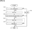
- Fig. 3 is a control flow performed within the ECU in the selection control of the first embodiment. These flows are executed when the P range or the N range is selected and the engine 1 is running while the vehicle is stopped.
- step S1 a determination is made as to whether or not the range position signal has moved from the P range or the N range, which are non-driving ranges, and selected the D range or the R range, which are driving ranges. If it is determined that such a selection has been made, the control flow proceeds to step S2; otherwise the control flow ends.
- step S2 a selection signal is transmitted to the ECU.
- step S3 an engagement instruction is outputted to the clutch 22. Note that when the engagement instruction is outputted to the clutch 22, a precharge pressure instruction that eliminates play of the clutch plates is outputted for a prescribed amount of time, and the transmitted torque capacity is produced after play is eliminated.
- step S10 a determination is made as to whether or not there is a request to increase the idling speed from the idling speed N1, which is the normal idling speed.
- requests accompany the running of air conditioning, drops in engine coolant temperature, and increased load from ancillary engine devices such as an alternator. If there is determined to be a request to increase the idling speed, the control flow proceeds to step S11; otherwise the control flow proceeds to step S12, where the idling speed is set to the normal idling speed N1, and then the control flow ends.
- a target speed for the engine speed Ne is set from N1 to N2 (> N1).
- the engine speed Ne is controlled using the throttle angle and ignition timing in a feedback loop. Specifically, when the target speed is changed from N1 to N2, the throttle angle is increased, making the engine speed Ne rise.
- step S13 a determination is made as to whether or not a selection signal has been received from the CVTCU.
- the control flow proceeds to step S14; otherwise the control flow ends with the idling speed set to N2.
- step S14 the target speed for the engine speed Ne is set to N3, which is lower than N2.
- N3 can be the same speed as N1, and can be a speed higher than N1 so long as inertial torque from the input-side rotating element is of a value that can be decreased.
- N3 can also be set to a speed lower than N1.
- retard control is more responsive than throttle-angle-based engine torque control, the engine speed Ne is able to be decreased effectively.
- step S15 a determination is made as to whether or not the engine speed Ne is less than or equal to N3.
- Ne is higher than N3
- the control flow returns to step S14 and steps S14 and S15 are repeated, and when Ne reaches a value less than or equal to N3, the control flow ends.
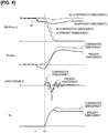
- Fig. 4 is a timing chart illustrating the selection control process of the first embodiment.
- a state at an initial point in time is such that the P range is selected and the idling speed is set to N2.
- thin solid lines and thin chain lines represent a comparative example in which the engine speed Ne is not changed from N2 and in which the clutch 22 has been engaged.
- Thick solid lines and thick chain lines represent the first embodiment when selection control is performed. Note that in the uppermost timing chart in Fig. 4 , the chain lines represent a turbine speed Nt, which is the speed of the input-side rotating element, and the solid lines represent the engine speed Ne. Further, Te represents engine torque, and Tc represents the transmitted torque capacity of the clutch 22.
- the driver operates the select lever 5 at time t1, and approximately 0.3 seconds later, at time t2, when the clutch 22 starts to have a transmitted torque capacity Tc, the turbine speed Nt immediately starts to drop. Accordingly, because load on the torque converter 21 is increased, the engine torque Te also starts to rise. Consequently, longitudinal G arises in an oscillatory manner, and the peak thereof is also comparatively high.
- the target speed for the engine speed Ne is very quickly set from N2 to N3.
- the engine torque Te thus becomes a negative torque, due to retard control, and the engine speed Ne is caused to drop immediately to N3.
- the engine speed Ne is caused to drop to N3 prior to time t2, at which the transmitted torque capacity of the clutch 22 starts being produced.
- the clutch 22 starts to have a transmitted torque capacity Tc, and inertial torque when the turbine speed Nt starts to drop can be suppressed. Because the peak of oscillations of longitudinal G can be suppressed, selection shock can be suppressed.
- the belt-type continuously variable transmission mechanism 23 was employed for the transmission
- another form of transmission can be adopted.
- the clutch 2 in the first embodiment can be a starter clutch that is inside the transmission.
- a configuration can be adopted in which the completion of engagement of the clutch 22 is detected, and the idling speed is restored to N2 from N3 when engagement of the clutch 22 is complete. Requests to increase the idling speed can thereby be satisfied.
- the completion of engagement of the clutch 22 can be detected with a timer, or the completion of engagement can be detected as a point when a relative difference in speed between the turbine speed Nt and a speed of an output shaft of the transmission is less than or equal to a prescribed value. Further, in the first embodiment, although the engine speed Ne was caused to drop prior to when the clutch 22 starts to have transmitted torque capacity, the clutch side can be controlled such that the clutch 22 is given transmitted torque capacity after the engine speed Ne drops to N3.
Landscapes
- Engineering & Computer Science (AREA)
- Mechanical Engineering (AREA)
- Chemical & Material Sciences (AREA)
- Combustion & Propulsion (AREA)
- General Engineering & Computer Science (AREA)
- Transportation (AREA)
- Automation & Control Theory (AREA)
- Signal Processing (AREA)
- Theoretical Computer Science (AREA)
- Control Of Vehicle Engines Or Engines For Specific Uses (AREA)
- Control Of Transmission Device (AREA)
- Electrical Control Of Air Or Fuel Supplied To Internal-Combustion Engine (AREA)
- Electrical Control Of Ignition Timing (AREA)
- Combined Controls Of Internal Combustion Engines (AREA)
Abstract
Description
- The present invention relates to a vehicle control method and a vehicle control apparatus whereby shock accompanying clutch engagement when switching from a non-driving range to a driving range as a result of the operation of a selection lever while the vehicle is stopped (referred to below as selection shock) is suppressed.
-
Patent Document 1 discloses technology that changes a target speed for an engine between a non-driving range and a driving range, and that changes a feedback gain when controlling for a target speed using feedback. - Patent Document 1: Japanese Laid-Open Patent Application No.
2006-90218 - However, with the technology of
Patent Document 1, because feedback gain is held for a prescribed amount of time even if switching from a non-driving range to a driving range, it is difficult to suppress selection shock. - An objective of the present invention is to provide a vehicle control method able to mitigate selection shock.
- In order to achieve the above objective, in a vehicle control method of the present invention, an idling speed of an engine is caused to drop within a prescribed amount of time needed for a clutch to switch from being disconnected to being connected when a shift range is switched from a non-driving range to a driving range.
- Accordingly, it is possible to suppress inertial torque from an input-side rotating element of the clutch, and selection shock can be suppressed.
-
-
Fig. 1 is a system diagram for a vehicle to which selection control has been applied in accordance with a first embodiment. -
Fig. 2 is a control flow diagram performed within a CVTCU in the selection control of the first embodiment. -
Fig. 3 is a control flow performed within an ECU in the selection control of the first embodiment. -
Fig. 4 is a timing chart illustrating a selection control process in the first embodiment. -
- 1
- Engine
- 2
- Automatic transmission
- 3
- Final gear
- 4
- Drive wheel
- 5
- Shift lever
- 5a
- Shift range
- 10
- Engine controller (ECU)
- 15
- CAN communication line
- 20
- Transmission controller (CVTCU)
- 21
- Torque converter
- 22
- Clutch
- 23
- Belt-type continuously variable transmission mechanism
-
Fig. 1 is a system diagram for a vehicle to which selection control of a first embodiment has been applied. Rotation outputted from anengine 1, which is an internal combustion engine, is inputted to anautomatic transmission 2. Rotation inputted to theautomatic transmission 2 is inputted to a belt-type continuouslyvariable transmission mechanism 23 via atorque converter 21 and aclutch 22. Theclutch 22 is a wet multi-plate clutch in which a plurality of clutch plates are stacked in an alternating manner. Theclutch 22 controls a transmitted torque capacity on the basis of a controlling hydraulic pressure supplied from a control valve (not shown). Note that in the case of the first embodiment, although an engagement element that achieves forward movement and an engagement element that achieves reverse movement in a forward/reverse switching mechanism (not shown) respectively correspond to theclutch 22, a one-way clutch can be provided in addition to the forward/reverse switching mechanism, and there is no particular limitation thereto. Rotation, the speed of which has been changed by the belt-type continuouslyvariable transmission mechanism 23, is transmitted to adrive wheel 10 via afinal gear 3. Theengine 1 has athrottle valve 1a that adjusts an intake air volume and anignition device 1b that is able to control ignition timing. - A shift lever 5 that is operated by a driver switches a range position of a
shift range 5a as a result of being operated. Theshift range 5a has a parking range (referred to below as a P range), a reverse range for reverse movement (referred to below as an R range), a neutral range (referred to below as an N range), and a drive range for forward movement (referred to below as a D range). Theshift range 5a outputs a range position signal that corresponds to the operative position of the shift lever 5. Theclutch 23 is disconnected when the P range or the N range (also referred to below as non-driving ranges) is selected, and theclutch 23 is connected when the R range or the D range (also referred to below as driving ranges) is selected. - An engine control unit 10 (referred to below as an ECU) outputs a control signal to the
throttle valve 1a and theignition device 1b of theengine 1 and controls running conditions (engine speed Ne and engine torque Te) of theengine 1. Anengine speed sensor 1c detects an engine speed Ne and outputs the engine speed Ne to the ECU. A transmission control unit 20 (referred to below as a CVTCU) receives the range position signal transmitted from theshift range 5a and controls the connection/disconnection of theclutch 22 and a gear ratio of the belt-type continuouslyvariable transmission mechanism 23. The ECU and the CVTCU are connected by a CANcommunication line 15 over which the mutual exchange of information is possible. - Selection control will now be described. When a non-driving range is selected, because the
clutch 22 is disconnected, theengine 1 is set to a prescribed idling speed. If ancillary devices driven by theengine 1 are not being run when theengine 1 has finished warming up, the idling speed is set to N1, which is a low speed at which self-sustaining rotation is possible. From this state, if the shift lever 5 is operated and the shift range selects a driving range, a controlling hydraulic pressure is supplied to theclutch 22, and torque is transmitted to thedrive wheel 4 via thefinal gear 3 upon the transmitted torque capacity being ensured. While a braking torque greater than a creep torque is being produced, which is a state in which the driver has depressed a brake pedal, the vehicle remains stopped. - At such time, torsion occurs in a power transmission path between the
engine 1 and thedrive wheel 4 and the vehicle body sinks due to the action of a suspension between thedrive wheel 4 and the vehicle body, or a counterforce acts on a mount between the power transmission path and the vehicle body and the vehicle body moves forward/backward and longitudinal acceleration G arises in the vehicle. When the engine speed Ne is set low, to N1, not much longitudinal acceleration G arises. However, while the engine is warming up or when an increase in idling speed is requested due to the running of ancillary devices, the engine speed Ne is set to N2, which is a high idling speed. In this case, because the clutch 22 is disconnected, while a non-driving range is selected a turbine runner of thetorque converter 21 and a rotating element on the engine-side of the clutch 22 (referred to below as an input-side rotating element) are turned together at a speed approaching N2 as the idling speed rises. From this state, if theshift range 5a selects a driving range, at the point in time that the transmitted torque capacity is ensured by the clutch 22, the speed of the input-side rotating element immediately drops from N2. This leads to an issue where inertial torque from the input-side rotating element is outputted, and the change in torque at the time of selection is increased and the selection shock that accompanies a change in longitudinal acceleration (referred to below as longitudinal G) is liable to increase. - Accordingly, in the first embodiment, in a state in which the idling speed is set to N2, which is a high speed, when the shift lever 5 is moved from a non-driving range and a driving range is selected, the engine speed Ne is caused to drop as much as possible prior to the transmitted torque capacity being ensured by the clutch 22, and the clutch 22 is engaged in a state subject to less inertial torque from the input-side rotating element, thereby suppressing selection shock.
-
Fig. 2 is a control flow performed within the CVTCU in the selection control of the first embodiment, andFig. 3 is a control flow performed within the ECU in the selection control of the first embodiment. These flows are executed when the P range or the N range is selected and theengine 1 is running while the vehicle is stopped. - In step S1, a determination is made as to whether or not the range position signal has moved from the P range or the N range, which are non-driving ranges, and selected the D range or the R range, which are driving ranges. If it is determined that such a selection has been made, the control flow proceeds to step S2; otherwise the control flow ends.
- In step S2, a selection signal is transmitted to the ECU.
- In step S3, an engagement instruction is outputted to the clutch 22. Note that when the engagement instruction is outputted to the clutch 22, a precharge pressure instruction that eliminates play of the clutch plates is outputted for a prescribed amount of time, and the transmitted torque capacity is produced after play is eliminated.
- In step S10, a determination is made as to whether or not there is a request to increase the idling speed from the idling speed N1, which is the normal idling speed. Such requests accompany the running of air conditioning, drops in engine coolant temperature, and increased load from ancillary engine devices such as an alternator. If there is determined to be a request to increase the idling speed, the control flow proceeds to step S11; otherwise the control flow proceeds to step S12, where the idling speed is set to the normal idling speed N1, and then the control flow ends.
- In step S11, a target speed for the engine speed Ne is set from N1 to N2 (> N1). Here, when a target speed is set, the engine speed Ne is controlled using the throttle angle and ignition timing in a feedback loop. Specifically, when the target speed is changed from N1 to N2, the throttle angle is increased, making the engine speed Ne rise.
- In step S13, a determination is made as to whether or not a selection signal has been received from the CVTCU. When a selection signal has been received, the control flow proceeds to step S14; otherwise the control flow ends with the idling speed set to N2.
- In step S14, the target speed for the engine speed Ne is set to N3, which is lower than N2. Here, when the target speed is changed from N2 to N3, the throttle angle is reduced, whereby the intake air volume of the
engine 1 is decreased, and retard control that causes ignition timing to be delayed is executed, causing the engine speed Ne to drop. N3 can be the same speed as N1, and can be a speed higher than N1 so long as inertial torque from the input-side rotating element is of a value that can be decreased. For the purpose of temporarily reducing speed, N3 can also be set to a speed lower than N1. Moreover, because retard control is more responsive than throttle-angle-based engine torque control, the engine speed Ne is able to be decreased effectively. However, with retard control, when gas resulting from incomplete combustion is supplied to a catalyzer, heating of the catalyzer is concern. For this reason, in the first embodiment, selection control is avoided when the normal idling speed N1, at which not much selection shock occurs, has been set. - In step S15, a determination is made as to whether or not the engine speed Ne is less than or equal to N3. When Ne is higher than N3, the control flow returns to step S14 and steps S14 and S15 are repeated, and when Ne reaches a value less than or equal to N3, the control flow ends.
-
Fig. 4 is a timing chart illustrating the selection control process of the first embodiment. A state at an initial point in time is such that the P range is selected and the idling speed is set to N2. In this chart, thin solid lines and thin chain lines represent a comparative example in which the engine speed Ne is not changed from N2 and in which the clutch 22 has been engaged. Thick solid lines and thick chain lines represent the first embodiment when selection control is performed. Note that in the uppermost timing chart inFig. 4 , the chain lines represent a turbine speed Nt, which is the speed of the input-side rotating element, and the solid lines represent the engine speed Ne. Further, Te represents engine torque, and Tc represents the transmitted torque capacity of the clutch 22. - In the comparative example, the driver operates the select lever 5 at time t1, and approximately 0.3 seconds later, at time t2, when the clutch 22 starts to have a transmitted torque capacity Tc, the turbine speed Nt immediately starts to drop. Accordingly, because load on the
torque converter 21 is increased, the engine torque Te also starts to rise. Consequently, longitudinal G arises in an oscillatory manner, and the peak thereof is also comparatively high. - In contrast, in the first embodiment, when the driver operates the select lever 5 and the shift range position is switched from the P range to the D range at time t1, the target speed for the engine speed Ne is very quickly set from N2 to N3. The engine torque Te thus becomes a negative torque, due to retard control, and the engine speed Ne is caused to drop immediately to N3. When this occurs, the engine speed Ne is caused to drop to N3 prior to time t2, at which the transmitted torque capacity of the clutch 22 starts being produced. Accordingly, at time t2, the clutch 22 starts to have a transmitted torque capacity Tc, and inertial torque when the turbine speed Nt starts to drop can be suppressed. Because the peak of oscillations of longitudinal G can be suppressed, selection shock can be suppressed.
- The following effects are achieved with the first embodiment, as described above.
- (1) In a method for controlling a vehicle in which a clutch 22 provided on a power transmission path between an
engine 1 and a drive wheel 5 is disconnected when ashift range 5a is a non-driving range and the clutch is connected when theshift range 5a is a driving range, theengine 1 is controlled to N2 (a prescribed idling speed), and an engine speed Ne is caused to drop from N2 within a prescribed amount of time needed for the clutch 22 to switch from being disconnected to being connected when theshift range 5a is switched from the non-driving range to the driving range. Accordingly, it is possible to suppress inertial torque from an input-side rotating element, and selection shock can be suppressed. - (2) An determination is made as to the presence of an increase idling speed request to set the prescribed idling speed to N2 (a second speed), which is higher than N1 (a first idling speed), and setting the prescribed idling speed to N2 upon determining the increase idling speed request is present, and setting the prescribed idling speed to N1 and maintaining N1 regardless of operation of the
shift range 5a upon determining the increase idling speed request is not present. Accordingly, in cases where there is no request to increase idling speed, retard control is avoided, whereby heating of the catalyzer, etc., due to gas resulting from incomplete combustion can be suppressed. - (3) When the prescribed idling speed is caused to drop, the drop is caused by retard control (delaying an ignition timing of the engine). Accordingly, the engine speed Ne can be reduced in a highly responsive and efficient manner.
- (4) When the prescribed idling speed is caused to drop, the drop is caused by decreasing an intake air volume of the engine. Specifically, a throttle angle is suppressed, whereby the engine speed Ne is caused to drop. Accordingly, the engine speed Ne can be reduced in an efficient manner. Because gas resulting from incomplete combustion is not produced as with retard control, the life of the catalyzer can be improved.
- (5) When the prescribed idling speed is caused to drop, a torque of the
engine 1 is controlled to a negative torque. Accordingly, the engine speed Ne can be caused to drop rapidly prior to when the clutch 22 starts to have a transmitted torque capacity. - (6) In an apparatus for controlling a vehicle provided with a clutch 22 that connects and disconnects a power transmission path between an
engine 1 and a drive wheel 5, and with ashift range 5a that is switchable between a driving range and a non-driving range, a CVTCU (clutch control unit) that disconnects the clutch 22 when theshift range 5a is in the non-driving range and that connects the clutch 22 when the shift range is in the driving range, and an ECU (engine control unit) that controls theengine 1 to a prescribed idling speed. The ECU causes theengine 1 to drop to a speed lower than N2 before the CVTCU finishes switching the clutch 22 from being disconnected to being connected when theshift range 5a is switched from the non-driving range to the driving range. Accordingly, it is possible to suppress inertial torque from an input-side rotating element, and selection shock can be suppressed. - Although a description of the present invention has been given on the basis of one embodiment, other configurations may be adopted for the specific configuration involved. In the first embodiment, although an example was given in which the belt-type continuously
variable transmission mechanism 23 was employed for the transmission, another form of transmission can be adopted. Further, the clutch 2 in the first embodiment can be a starter clutch that is inside the transmission. Further, in the first embodiment, although after the idling speed is caused to drop from N2 to N3 the idling speed was continuously maintained at N3 without being restored to N2, a configuration can be adopted in which the completion of engagement of the clutch 22 is detected, and the idling speed is restored to N2 from N3 when engagement of the clutch 22 is complete. Requests to increase the idling speed can thereby be satisfied. The completion of engagement of the clutch 22 can be detected with a timer, or the completion of engagement can be detected as a point when a relative difference in speed between the turbine speed Nt and a speed of an output shaft of the transmission is less than or equal to a prescribed value. Further, in the first embodiment, although the engine speed Ne was caused to drop prior to when the clutch 22 starts to have transmitted torque capacity, the clutch side can be controlled such that the clutch 22 is given transmitted torque capacity after the engine speed Ne drops to N3.
Claims (6)
- A method for controlling a vehicle in which a clutch provided on a power transmission path between an engine and a drive wheel is disconnected when a shift range is a non-driving range and the clutch is connected when the shift range is a driving range, the method characterized in comprising:controlling the engine to a prescribed idling speed; andcausing the prescribed idling speed to drop within a prescribed amount of time needed for the clutch to switch from being disconnected to being connected when the shift range is switched from the non-driving range to the driving range.
- The vehicle control method according to claim 1, wherein
determining whether an increase idling speed request is present to set the prescribed idling speed to a second speed higher than a first idling speed, and
setting the prescribed idling speed to the second speed upon determining the increase idling speed request is present, and
setting the prescribed idling speed to the first idling speed and maintaining the first idling speed regardless of operation of the shift range upon determining the increase idling speed request is not present. - The vehicle control method according to claim 1 or 2, wherein the drop is caused by delaying an ignition timing of the engine when the prescribed idling speed is caused to drop.
- The vehicle control method according to any one of claims 1 to 3, wherein the drop is caused by decreasing an intake air volume of the engine when the prescribed idling speed is caused to drop.
- The vehicle control method according to any one of claims 1 to 4, wherein a torque of the engine is controlled to a negative torque when the prescribed idling speed is caused to drop.
- An apparatus for controlling a vehicle provided with a clutch that connects and disconnects a power transmission path between an engine and a drive wheel, and with a shift range that is switchable between a driving range and a non-driving range, the apparatus characterized in comprising:a clutch control unit that disconnects the clutch when the shift range is in the non-driving range and that connects the clutch when the shift range is in the driving range; andan engine control unit that controls the engine to a prescribed idling speed;the engine control unit causing the engine to drop to a speed lower than the prescribed idling speed before the clutch control unit finishes switching the clutch from being disconnected to being connected when the shift range is switched from the non-driving range to the driving range.
Applications Claiming Priority (1)
| Application Number | Priority Date | Filing Date | Title |
|---|---|---|---|
| PCT/JP2017/002276 WO2018138762A1 (en) | 2017-01-24 | 2017-01-24 | Method for controlling vehicle and device for controlling vehicle |
Publications (3)
| Publication Number | Publication Date |
|---|---|
| EP3575582A1 true EP3575582A1 (en) | 2019-12-04 |
| EP3575582A4 EP3575582A4 (en) | 2019-12-11 |
| EP3575582B1 EP3575582B1 (en) | 2021-04-14 |
Family
ID=62979106
Family Applications (1)
| Application Number | Title | Priority Date | Filing Date |
|---|---|---|---|
| EP17894426.0A Active EP3575582B1 (en) | 2017-01-24 | 2017-01-24 | Method for controlling vehicle and device for controlling vehicle |
Country Status (5)
| Country | Link |
|---|---|
| US (1) | US11840973B2 (en) |
| EP (1) | EP3575582B1 (en) |
| JP (1) | JP6822487B2 (en) |
| CN (1) | CN110192017B (en) |
| WO (1) | WO2018138762A1 (en) |
Family Cites Families (25)
| Publication number | Priority date | Publication date | Assignee | Title |
|---|---|---|---|---|
| JPS4942491Y1 (en) * | 1969-08-11 | 1974-11-20 | ||
| US4694709A (en) * | 1984-09-08 | 1987-09-22 | Mazda Motor Corporation | Control of a vehicle automatic transmission |
| JPS6317207A (en) * | 1986-07-08 | 1988-01-25 | Fuji Electric Co Ltd | Ozone-generation tube |
| JPH0291444A (en) * | 1988-09-28 | 1990-03-30 | Nissan Motor Co Ltd | Idling speed controller of internal combustion engine with automatic speed change gear |
| JP2862643B2 (en) * | 1990-06-27 | 1999-03-03 | マツダ株式会社 | Control device for automatic transmission and engine |
| US5199326A (en) * | 1990-11-28 | 1993-04-06 | Toyota Jidosha Kabushiki Kaisha | Idle up of engine of automobile according to elevation of transmission oil temperature |
| JP3293902B2 (en) * | 1991-10-11 | 2002-06-17 | 富士重工業株式会社 | Control system for vehicle engine |
| JP2929895B2 (en) * | 1993-05-06 | 1999-08-03 | トヨタ自動車株式会社 | Idle speed control device |
| JP3633282B2 (en) * | 1998-06-04 | 2005-03-30 | トヨタ自動車株式会社 | Vehicle engine stop control device |
| JP2000337495A (en) * | 1999-05-26 | 2000-12-05 | Hitachi Ltd | Control device for automatic transmission |
| EP1350950B1 (en) | 2002-03-29 | 2005-06-01 | Mazda Motor Corporation | Control apparatus for a powertrain, powertrain, control method thereof, computer-readable storage medium, and computer program |
| US7036484B2 (en) * | 2003-04-16 | 2006-05-02 | General Motors Corporation | Idle speed control using alternator |
| US6942530B1 (en) * | 2004-01-22 | 2005-09-13 | Brunswick Corporation | Engine control strategy for a marine propulsion system for improving shifting |
| US7141000B2 (en) | 2004-02-19 | 2006-11-28 | Nissan Motor Co., Ltd. | Engine idle speed control device |
| JP4375059B2 (en) * | 2004-03-01 | 2009-12-02 | 日産自動車株式会社 | Engine idle speed control device |
| DE602005000416T2 (en) * | 2004-03-01 | 2007-05-16 | Nissan Motor Co., Ltd., Yokohama | Device for regulating the idle speed |
| JP2006090218A (en) | 2004-09-24 | 2006-04-06 | Toyota Motor Corp | Internal combustion engine |
| JP4792760B2 (en) * | 2005-02-09 | 2011-10-12 | トヨタ自動車株式会社 | Vehicle start control device |
| JP2008255916A (en) * | 2007-04-06 | 2008-10-23 | Nissan Motor Co Ltd | Vehicle control device |
| JP4922317B2 (en) * | 2009-01-09 | 2012-04-25 | 本田技研工業株式会社 | Engine torque control device |
| US8579762B2 (en) | 2010-07-09 | 2013-11-12 | GM Global Technology Operations LLC | Negative torque upshift offgoing clutch control systems and methods |
| DE102010040279A1 (en) * | 2010-09-06 | 2012-03-08 | Robert Bosch Gmbh | Method and device for operating a drive unit of a motor vehicle |
| JP5691910B2 (en) * | 2011-07-25 | 2015-04-01 | 三菱自動車工業株式会社 | Engine control device |
| CN103381822B (en) | 2012-05-04 | 2018-04-13 | 福特环球技术公司 | Method and system for adaptive change power train disconnect-type clutch transmission function |
| JP5920183B2 (en) * | 2012-11-16 | 2016-05-18 | トヨタ自動車株式会社 | Control device for internal combustion engine |
-
2017
- 2017-01-24 CN CN201780082667.2A patent/CN110192017B/en active Active
- 2017-01-24 EP EP17894426.0A patent/EP3575582B1/en active Active
- 2017-01-24 WO PCT/JP2017/002276 patent/WO2018138762A1/en not_active Ceased
- 2017-01-24 US US16/472,260 patent/US11840973B2/en active Active
- 2017-01-24 JP JP2018563958A patent/JP6822487B2/en active Active
Also Published As
| Publication number | Publication date |
|---|---|
| EP3575582A4 (en) | 2019-12-11 |
| CN110192017A (en) | 2019-08-30 |
| CN110192017B (en) | 2020-09-01 |
| JPWO2018138762A1 (en) | 2019-07-11 |
| WO2018138762A1 (en) | 2018-08-02 |
| US11840973B2 (en) | 2023-12-12 |
| US20190323444A1 (en) | 2019-10-24 |
| JP6822487B2 (en) | 2021-01-27 |
| EP3575582B1 (en) | 2021-04-14 |
Similar Documents
| Publication | Publication Date | Title |
|---|---|---|
| JP5323748B2 (en) | Hydraulic control device for automatic transmission | |
| US9815466B2 (en) | Lock-up clutch control device for vehicle | |
| EP2416029A1 (en) | A vehicular power transmission control apparatus | |
| CN111623113B (en) | Clutch control method for first gear and second gear increasing in starting process of double-clutch transmission | |
| CA3014161C (en) | Control method and control device for transmission mechanism | |
| US10415699B2 (en) | Vehicle lock-up control method and control device | |
| JP2012122497A (en) | Vehicle control apparatus | |
| JP6288279B2 (en) | Vehicle lock-up clutch control device | |
| EP3575582B1 (en) | Method for controlling vehicle and device for controlling vehicle | |
| CN104309607B (en) | Method and device for controlling transmission | |
| JP5467973B2 (en) | Automatic transmission for vehicle | |
| JP4566171B2 (en) | Shift control device for automatic transmission | |
| JP2014231889A (en) | Transmission controller | |
| JPWO2018143249A1 (en) | Control device and control method for lock-up clutch | |
| KR20080024720A (en) | Controlling method for damper clutch of automatic transmission and system thereof | |
| JP2005172078A (en) | Torque converter lockup control device | |
| JPH05209545A (en) | Controller of engine for vehicle | |
| JP2001182825A (en) | Creep force control device for automatic transmission for vehicles | |
| JP2006037917A (en) | Vehicle creep running control device | |
| JP2001295920A (en) | Creep force control device for automatic transmission for vehicles | |
| JP6076754B2 (en) | Internal combustion engine control device | |
| JP6481536B2 (en) | ENGINE CONTROL METHOD AND ENGINE CONTROL DEVICE | |
| JP5350652B2 (en) | Engine control apparatus and control method | |
| US20200208740A1 (en) | Lock-up clutch control method for vehicle, and lock-up clutch control device for vehicle | |
| KR20080053152A (en) | How to control damper clutch in automatic transmission vehicle |
Legal Events
| Date | Code | Title | Description |
|---|---|---|---|
| STAA | Information on the status of an ep patent application or granted ep patent |
Free format text: STATUS: THE INTERNATIONAL PUBLICATION HAS BEEN MADE |
|
| PUAI | Public reference made under article 153(3) epc to a published international application that has entered the european phase |
Free format text: ORIGINAL CODE: 0009012 |
|
| STAA | Information on the status of an ep patent application or granted ep patent |
Free format text: STATUS: REQUEST FOR EXAMINATION WAS MADE |
|
| 17P | Request for examination filed |
Effective date: 20190809 |
|
| AK | Designated contracting states |
Kind code of ref document: A1 Designated state(s): AL AT BE BG CH CY CZ DE DK EE ES FI FR GB GR HR HU IE IS IT LI LT LU LV MC MK MT NL NO PL PT RO RS SE SI SK SM TR |
|
| A4 | Supplementary search report drawn up and despatched |
Effective date: 20191111 |
|
| RIC1 | Information provided on ipc code assigned before grant |
Ipc: F02D 29/00 20060101ALI20191105BHEP Ipc: F02D 41/16 20060101AFI20191105BHEP Ipc: F02D 43/00 20060101ALI20191105BHEP Ipc: F02P 5/15 20060101ALI20191105BHEP |
|
| GRAP | Despatch of communication of intention to grant a patent |
Free format text: ORIGINAL CODE: EPIDOSNIGR1 |
|
| STAA | Information on the status of an ep patent application or granted ep patent |
Free format text: STATUS: GRANT OF PATENT IS INTENDED |
|
| INTG | Intention to grant announced |
Effective date: 20201218 |
|
| GRAS | Grant fee paid |
Free format text: ORIGINAL CODE: EPIDOSNIGR3 |
|
| GRAA | (expected) grant |
Free format text: ORIGINAL CODE: 0009210 |
|
| STAA | Information on the status of an ep patent application or granted ep patent |
Free format text: STATUS: THE PATENT HAS BEEN GRANTED |
|
| AK | Designated contracting states |
Kind code of ref document: B1 Designated state(s): AL AT BE BG CH CY CZ DE DK EE ES FI FR GB GR HR HU IE IS IT LI LT LU LV MC MK MT NL NO PL PT RO RS SE SI SK SM TR |
|
| REG | Reference to a national code |
Ref country code: GB Ref legal event code: FG4D |
|
| REG | Reference to a national code |
Ref country code: CH Ref legal event code: EP |
|
| REG | Reference to a national code |
Ref country code: DE Ref legal event code: R096 Ref document number: 602017036915 Country of ref document: DE |
|
| REG | Reference to a national code |
Ref country code: IE Ref legal event code: FG4D |
|
| REG | Reference to a national code |
Ref country code: AT Ref legal event code: REF Ref document number: 1382589 Country of ref document: AT Kind code of ref document: T Effective date: 20210515 |
|
| REG | Reference to a national code |
Ref country code: LT Ref legal event code: MG9D |
|
| REG | Reference to a national code |
Ref country code: AT Ref legal event code: MK05 Ref document number: 1382589 Country of ref document: AT Kind code of ref document: T Effective date: 20210414 |
|
| REG | Reference to a national code |
Ref country code: NL Ref legal event code: MP Effective date: 20210414 |
|
| PG25 | Lapsed in a contracting state [announced via postgrant information from national office to epo] |
Ref country code: NL Free format text: LAPSE BECAUSE OF FAILURE TO SUBMIT A TRANSLATION OF THE DESCRIPTION OR TO PAY THE FEE WITHIN THE PRESCRIBED TIME-LIMIT Effective date: 20210414 Ref country code: BG Free format text: LAPSE BECAUSE OF FAILURE TO SUBMIT A TRANSLATION OF THE DESCRIPTION OR TO PAY THE FEE WITHIN THE PRESCRIBED TIME-LIMIT Effective date: 20210714 Ref country code: AT Free format text: LAPSE BECAUSE OF FAILURE TO SUBMIT A TRANSLATION OF THE DESCRIPTION OR TO PAY THE FEE WITHIN THE PRESCRIBED TIME-LIMIT Effective date: 20210414 Ref country code: HR Free format text: LAPSE BECAUSE OF FAILURE TO SUBMIT A TRANSLATION OF THE DESCRIPTION OR TO PAY THE FEE WITHIN THE PRESCRIBED TIME-LIMIT Effective date: 20210414 Ref country code: FI Free format text: LAPSE BECAUSE OF FAILURE TO SUBMIT A TRANSLATION OF THE DESCRIPTION OR TO PAY THE FEE WITHIN THE PRESCRIBED TIME-LIMIT Effective date: 20210414 Ref country code: LT Free format text: LAPSE BECAUSE OF FAILURE TO SUBMIT A TRANSLATION OF THE DESCRIPTION OR TO PAY THE FEE WITHIN THE PRESCRIBED TIME-LIMIT Effective date: 20210414 |
|
| PG25 | Lapsed in a contracting state [announced via postgrant information from national office to epo] |
Ref country code: GR Free format text: LAPSE BECAUSE OF FAILURE TO SUBMIT A TRANSLATION OF THE DESCRIPTION OR TO PAY THE FEE WITHIN THE PRESCRIBED TIME-LIMIT Effective date: 20210715 Ref country code: IS Free format text: LAPSE BECAUSE OF FAILURE TO SUBMIT A TRANSLATION OF THE DESCRIPTION OR TO PAY THE FEE WITHIN THE PRESCRIBED TIME-LIMIT Effective date: 20210814 Ref country code: SE Free format text: LAPSE BECAUSE OF FAILURE TO SUBMIT A TRANSLATION OF THE DESCRIPTION OR TO PAY THE FEE WITHIN THE PRESCRIBED TIME-LIMIT Effective date: 20210414 Ref country code: RS Free format text: LAPSE BECAUSE OF FAILURE TO SUBMIT A TRANSLATION OF THE DESCRIPTION OR TO PAY THE FEE WITHIN THE PRESCRIBED TIME-LIMIT Effective date: 20210414 Ref country code: LV Free format text: LAPSE BECAUSE OF FAILURE TO SUBMIT A TRANSLATION OF THE DESCRIPTION OR TO PAY THE FEE WITHIN THE PRESCRIBED TIME-LIMIT Effective date: 20210414 Ref country code: PT Free format text: LAPSE BECAUSE OF FAILURE TO SUBMIT A TRANSLATION OF THE DESCRIPTION OR TO PAY THE FEE WITHIN THE PRESCRIBED TIME-LIMIT Effective date: 20210816 Ref country code: NO Free format text: LAPSE BECAUSE OF FAILURE TO SUBMIT A TRANSLATION OF THE DESCRIPTION OR TO PAY THE FEE WITHIN THE PRESCRIBED TIME-LIMIT Effective date: 20210714 Ref country code: PL Free format text: LAPSE BECAUSE OF FAILURE TO SUBMIT A TRANSLATION OF THE DESCRIPTION OR TO PAY THE FEE WITHIN THE PRESCRIBED TIME-LIMIT Effective date: 20210414 |
|
| REG | Reference to a national code |
Ref country code: DE Ref legal event code: R097 Ref document number: 602017036915 Country of ref document: DE |
|
| PG25 | Lapsed in a contracting state [announced via postgrant information from national office to epo] |
Ref country code: RO Free format text: LAPSE BECAUSE OF FAILURE TO SUBMIT A TRANSLATION OF THE DESCRIPTION OR TO PAY THE FEE WITHIN THE PRESCRIBED TIME-LIMIT Effective date: 20210414 Ref country code: CZ Free format text: LAPSE BECAUSE OF FAILURE TO SUBMIT A TRANSLATION OF THE DESCRIPTION OR TO PAY THE FEE WITHIN THE PRESCRIBED TIME-LIMIT Effective date: 20210414 Ref country code: DK Free format text: LAPSE BECAUSE OF FAILURE TO SUBMIT A TRANSLATION OF THE DESCRIPTION OR TO PAY THE FEE WITHIN THE PRESCRIBED TIME-LIMIT Effective date: 20210414 Ref country code: SM Free format text: LAPSE BECAUSE OF FAILURE TO SUBMIT A TRANSLATION OF THE DESCRIPTION OR TO PAY THE FEE WITHIN THE PRESCRIBED TIME-LIMIT Effective date: 20210414 Ref country code: SK Free format text: LAPSE BECAUSE OF FAILURE TO SUBMIT A TRANSLATION OF THE DESCRIPTION OR TO PAY THE FEE WITHIN THE PRESCRIBED TIME-LIMIT Effective date: 20210414 Ref country code: ES Free format text: LAPSE BECAUSE OF FAILURE TO SUBMIT A TRANSLATION OF THE DESCRIPTION OR TO PAY THE FEE WITHIN THE PRESCRIBED TIME-LIMIT Effective date: 20210414 Ref country code: EE Free format text: LAPSE BECAUSE OF FAILURE TO SUBMIT A TRANSLATION OF THE DESCRIPTION OR TO PAY THE FEE WITHIN THE PRESCRIBED TIME-LIMIT Effective date: 20210414 |
|
| PLBE | No opposition filed within time limit |
Free format text: ORIGINAL CODE: 0009261 |
|
| STAA | Information on the status of an ep patent application or granted ep patent |
Free format text: STATUS: NO OPPOSITION FILED WITHIN TIME LIMIT |
|
| 26N | No opposition filed |
Effective date: 20220117 |
|
| PG25 | Lapsed in a contracting state [announced via postgrant information from national office to epo] |
Ref country code: IS Free format text: LAPSE BECAUSE OF FAILURE TO SUBMIT A TRANSLATION OF THE DESCRIPTION OR TO PAY THE FEE WITHIN THE PRESCRIBED TIME-LIMIT Effective date: 20210814 Ref country code: AL Free format text: LAPSE BECAUSE OF FAILURE TO SUBMIT A TRANSLATION OF THE DESCRIPTION OR TO PAY THE FEE WITHIN THE PRESCRIBED TIME-LIMIT Effective date: 20210414 |
|
| PG25 | Lapsed in a contracting state [announced via postgrant information from national office to epo] |
Ref country code: IT Free format text: LAPSE BECAUSE OF FAILURE TO SUBMIT A TRANSLATION OF THE DESCRIPTION OR TO PAY THE FEE WITHIN THE PRESCRIBED TIME-LIMIT Effective date: 20210414 |
|
| PG25 | Lapsed in a contracting state [announced via postgrant information from national office to epo] |
Ref country code: MC Free format text: LAPSE BECAUSE OF FAILURE TO SUBMIT A TRANSLATION OF THE DESCRIPTION OR TO PAY THE FEE WITHIN THE PRESCRIBED TIME-LIMIT Effective date: 20210414 |
|
| REG | Reference to a national code |
Ref country code: CH Ref legal event code: PL |
|
| REG | Reference to a national code |
Ref country code: BE Ref legal event code: MM Effective date: 20220131 |
|
| PG25 | Lapsed in a contracting state [announced via postgrant information from national office to epo] |
Ref country code: LU Free format text: LAPSE BECAUSE OF NON-PAYMENT OF DUE FEES Effective date: 20220124 |
|
| PG25 | Lapsed in a contracting state [announced via postgrant information from national office to epo] |
Ref country code: BE Free format text: LAPSE BECAUSE OF NON-PAYMENT OF DUE FEES Effective date: 20220131 |
|
| PG25 | Lapsed in a contracting state [announced via postgrant information from national office to epo] |
Ref country code: LI Free format text: LAPSE BECAUSE OF NON-PAYMENT OF DUE FEES Effective date: 20220131 Ref country code: CH Free format text: LAPSE BECAUSE OF NON-PAYMENT OF DUE FEES Effective date: 20220131 |
|
| PG25 | Lapsed in a contracting state [announced via postgrant information from national office to epo] |
Ref country code: IE Free format text: LAPSE BECAUSE OF NON-PAYMENT OF DUE FEES Effective date: 20220124 |
|
| PG25 | Lapsed in a contracting state [announced via postgrant information from national office to epo] |
Ref country code: MK Free format text: LAPSE BECAUSE OF FAILURE TO SUBMIT A TRANSLATION OF THE DESCRIPTION OR TO PAY THE FEE WITHIN THE PRESCRIBED TIME-LIMIT Effective date: 20210414 Ref country code: CY Free format text: LAPSE BECAUSE OF FAILURE TO SUBMIT A TRANSLATION OF THE DESCRIPTION OR TO PAY THE FEE WITHIN THE PRESCRIBED TIME-LIMIT Effective date: 20210414 |
|
| PG25 | Lapsed in a contracting state [announced via postgrant information from national office to epo] |
Ref country code: HU Free format text: LAPSE BECAUSE OF FAILURE TO SUBMIT A TRANSLATION OF THE DESCRIPTION OR TO PAY THE FEE WITHIN THE PRESCRIBED TIME-LIMIT; INVALID AB INITIO Effective date: 20170124 |
|
| PG25 | Lapsed in a contracting state [announced via postgrant information from national office to epo] |
Ref country code: TR Free format text: LAPSE BECAUSE OF FAILURE TO SUBMIT A TRANSLATION OF THE DESCRIPTION OR TO PAY THE FEE WITHIN THE PRESCRIBED TIME-LIMIT Effective date: 20210414 |
|
| PG25 | Lapsed in a contracting state [announced via postgrant information from national office to epo] |
Ref country code: MT Free format text: LAPSE BECAUSE OF FAILURE TO SUBMIT A TRANSLATION OF THE DESCRIPTION OR TO PAY THE FEE WITHIN THE PRESCRIBED TIME-LIMIT Effective date: 20210414 |
|
| PGFP | Annual fee paid to national office [announced via postgrant information from national office to epo] |
Ref country code: GB Payment date: 20251219 Year of fee payment: 10 |
|
| PGFP | Annual fee paid to national office [announced via postgrant information from national office to epo] |
Ref country code: FR Payment date: 20251218 Year of fee payment: 10 |
|
| PGFP | Annual fee paid to national office [announced via postgrant information from national office to epo] |
Ref country code: DE Payment date: 20251217 Year of fee payment: 10 |