EP3575449A1 - Plated steel wire, steel cord, and rubber-plated steel wire composite - Google Patents
Plated steel wire, steel cord, and rubber-plated steel wire composite Download PDFInfo
- Publication number
- EP3575449A1 EP3575449A1 EP18745430.1A EP18745430A EP3575449A1 EP 3575449 A1 EP3575449 A1 EP 3575449A1 EP 18745430 A EP18745430 A EP 18745430A EP 3575449 A1 EP3575449 A1 EP 3575449A1
- Authority
- EP
- European Patent Office
- Prior art keywords
- steel wire
- film layer
- mass
- plated steel
- plating film
- Prior art date
- Legal status (The legal status is an assumption and is not a legal conclusion. Google has not performed a legal analysis and makes no representation as to the accuracy of the status listed.)
- Withdrawn
Links
Images

Classifications
-
- C—CHEMISTRY; METALLURGY
- C25—ELECTROLYTIC OR ELECTROPHORETIC PROCESSES; APPARATUS THEREFOR
- C25D—PROCESSES FOR THE ELECTROLYTIC OR ELECTROPHORETIC PRODUCTION OF COATINGS; ELECTROFORMING; APPARATUS THEREFOR
- C25D7/00—Electroplating characterised by the article coated
- C25D7/06—Wires; Strips; Foils
- C25D7/0607—Wires
-
- B—PERFORMING OPERATIONS; TRANSPORTING
- B60—VEHICLES IN GENERAL
- B60C—VEHICLE TYRES; TYRE INFLATION; TYRE CHANGING; CONNECTING VALVES TO INFLATABLE ELASTIC BODIES IN GENERAL; DEVICES OR ARRANGEMENTS RELATED TO TYRES
- B60C9/00—Reinforcements or ply arrangement of pneumatic tyres
- B60C9/0007—Reinforcements made of metallic elements, e.g. cords, yarns, filaments or fibres made from metal
-
- B—PERFORMING OPERATIONS; TRANSPORTING
- B60—VEHICLES IN GENERAL
- B60C—VEHICLE TYRES; TYRE INFLATION; TYRE CHANGING; CONNECTING VALVES TO INFLATABLE ELASTIC BODIES IN GENERAL; DEVICES OR ARRANGEMENTS RELATED TO TYRES
- B60C9/00—Reinforcements or ply arrangement of pneumatic tyres
- B60C9/005—Reinforcements made of different materials, e.g. hybrid or composite cords
-
- C—CHEMISTRY; METALLURGY
- C25—ELECTROLYTIC OR ELECTROPHORETIC PROCESSES; APPARATUS THEREFOR
- C25D—PROCESSES FOR THE ELECTROLYTIC OR ELECTROPHORETIC PRODUCTION OF COATINGS; ELECTROFORMING; APPARATUS THEREFOR
- C25D3/00—Electroplating: Baths therefor
- C25D3/02—Electroplating: Baths therefor from solutions
- C25D3/56—Electroplating: Baths therefor from solutions of alloys
- C25D3/565—Electroplating: Baths therefor from solutions of alloys containing more than 50% by weight of zinc
-
- C—CHEMISTRY; METALLURGY
- C25—ELECTROLYTIC OR ELECTROPHORETIC PROCESSES; APPARATUS THEREFOR
- C25D—PROCESSES FOR THE ELECTROLYTIC OR ELECTROPHORETIC PRODUCTION OF COATINGS; ELECTROFORMING; APPARATUS THEREFOR
- C25D5/00—Electroplating characterised by the process; Pretreatment or after-treatment of workpieces
- C25D5/48—After-treatment of electroplated surfaces
- C25D5/50—After-treatment of electroplated surfaces by heat-treatment
-
- D—TEXTILES; PAPER
- D07—ROPES; CABLES OTHER THAN ELECTRIC
- D07B—ROPES OR CABLES IN GENERAL
- D07B1/00—Constructional features of ropes or cables
- D07B1/06—Ropes or cables built-up from metal wires, e.g. of section wires around a hemp core
- D07B1/0606—Reinforcing cords for rubber or plastic articles
- D07B1/0666—Reinforcing cords for rubber or plastic articles the wires being characterised by an anti-corrosive or adhesion promoting coating
-
- B—PERFORMING OPERATIONS; TRANSPORTING
- B60—VEHICLES IN GENERAL
- B60C—VEHICLE TYRES; TYRE INFLATION; TYRE CHANGING; CONNECTING VALVES TO INFLATABLE ELASTIC BODIES IN GENERAL; DEVICES OR ARRANGEMENTS RELATED TO TYRES
- B60C9/00—Reinforcements or ply arrangement of pneumatic tyres
- B60C9/0007—Reinforcements made of metallic elements, e.g. cords, yarns, filaments or fibres made from metal
- B60C2009/0014—Surface treatments of steel cords
-
- B—PERFORMING OPERATIONS; TRANSPORTING
- B60—VEHICLES IN GENERAL
- B60C—VEHICLE TYRES; TYRE INFLATION; TYRE CHANGING; CONNECTING VALVES TO INFLATABLE ELASTIC BODIES IN GENERAL; DEVICES OR ARRANGEMENTS RELATED TO TYRES
- B60C9/00—Reinforcements or ply arrangement of pneumatic tyres
- B60C9/18—Structure or arrangement of belts or breakers, crown-reinforcing or cushioning layers
-
- C—CHEMISTRY; METALLURGY
- C25—ELECTROLYTIC OR ELECTROPHORETIC PROCESSES; APPARATUS THEREFOR
- C25D—PROCESSES FOR THE ELECTROLYTIC OR ELECTROPHORETIC PRODUCTION OF COATINGS; ELECTROFORMING; APPARATUS THEREFOR
- C25D5/00—Electroplating characterised by the process; Pretreatment or after-treatment of workpieces
- C25D5/34—Pretreatment of metallic surfaces to be electroplated
- C25D5/36—Pretreatment of metallic surfaces to be electroplated of iron or steel
Definitions
- the present invention relates to a plated steel wire, a steel cord and a rubber-plated steel wire composite.
- a steel cord obtained by twisting a plurality of steel wires whose surfaces are brass plated (copper-zinc alloy plated) and in which the surfaces of such brass-plating film layers are further covered with rubber, for example.
- a steel cord plated steel cord
- steel wire obtained by twisting a plurality of steel wires whose surfaces are brass plated (copper-zinc alloy plated) and in which the surfaces of such brass-plating film layers are further covered with rubber, for example.
- the rubber to be used for the tire, the conveyor, and so on is penetrated by water and oxygen, and various additives are used for the rubber product in order to give the rubber desirable capability. Therefore, when the interior of the rubber product contains water, the steel wire is exposed to a corrosive environment, resulting in corrosion.
- the rubber product is scratched by various external internal factors during use, and water easily infiltrates, whereby the corrosion of the steel wire is sometimes promoted.
- the rubber peels from the steel cord with the corrosion, or the steel cord fractures earlier than its original fatigue life due to the corrosion fatigue, so that the life of the rubber product becomes shorter than the original fatigue life of the steel cord.
- Patent Document 1 As techniques of improving corrosion resistance of the steel wire, there have been proposed a technique of hot dipping with Zn having sacrificial anticorrosive ability with respect to a steel wire being a base material of a steel cord (for example, Patent Document 1), and a technique of hot dipping with a Zn-Al alloy (for example, Patent Document 2).
- Patent Document 3 As a further technique of suppressing the corrosion of the steel wire, for example, there has been proposed a technique of plating at least one steel wire located more closely to the interior than an outermost layer strand of the steel cord with Zn, Al, and Cr being metals each having a larger ionization tendency than iron (for example, Patent Document 3).
- Patent Document 4 As a technique of improving corrosion resistance of a Zn-plating film layer given the steel wire, there has been proposed a technique of giving Zn plating in which particles of metals baser than Zn, such as Mg, Al, Ti, and Mn, have been dispersed, by electroplating (for example, Patent Document 4). Otherwise, as a technique of improving the corrosion resistance of a plating film layer by alloy plating, there has been proposed a technique of giving Zn-Ni alloy plating in which a Ni concentration of an uppermost surface layer portion of the plating film layer is set to 0 to 1 mass% and a Ni concentration of an innermost layer portion thereof is set to 5 to 20 mass% and whose composition is continuously changed (for example, Patent Document 5).
- Thickening of the plating film not only increases costs at the occasion of the plating, but also, for example, in a case of using a steel cord composed of hot-dipped steel wires for reinforcing the tire, increases a weight of a tire due to a plating film thickness, resulting in a deterioration in fuel consumption of an automobile, and it is therefore not preferable that the plating film thickness becomes large.
- Patent Document 4 allows a plating film thickness to be made small by using the electroplating, and moreover, allows durability of Zn to be improved because Mg, Al, Ti, Mn, and so on dispersed in a Zn-plating film layer are more likely to melt than Zn, corrosion resistance of the entire plating film layer has not been sufficient.
- Patent Document 5 suppresses peeling of a plating film from the steel wire at a time of wire drawing by continuously changing the composition of the plating film layer, a wire diameter after final wire drawing is 1 mm, and in a case of aiming at a further smaller diameter, the peeling of the plating film from the steel wire or cracking in the plating film layer occurs, and these each become a starting point of fatigue fracture due to corrosion of the steel wire.
- the conventional techniques have not made it possible to suppress occurrence of corrosion of the steel wire and progress thereof and sufficiently suppress peeling of rubber from the steel cord or corrosion fatigue while making a plating film thickness small.
- an object of the present invention is to provide a plated steel wire processable to a thin wire, a steel cord using the plated steel wires and a rubber-plated steel wire composite (rubber-steel cord composite), which allow a deterioration in adhesiveness to rubber and the corrosion fatigue to be suppressed by suppressing the occurrence of corrosion of the steel wire and the progress thereof even though the plating film thickness is made small.
- the present inventors have conducted a keen study regarding corrosion of a Zn-plated steel wire in order to solve the above-described problems. As a result, it has become clear that although the corrosion of the steel wire can be sufficiently suppressed by hot-dip Zn plating, insufficient corrosion resistance of a plating film itself is linked to early wear of the plating film, a deterioration in adhesiveness to rubber, and an early fracture of a steel cord due to progress of corrosion fatigue. While further conducting a keen study, the present inventors have known that when Zn alloy plating excellent in corrosion resistance of the plating film is given the steel wire by electroplating capable of making a plating film thickness small, a hard intermetallic compound is sometimes present in the electric Zn alloy plating film layer.
- the intermetallic compound cannot sufficiently follow an elongation of a base steel wire at a time of wire drawing of a plated steel wire due to poor plastic deformability, so that a crack occurs at a present location of the intermetallic compound in the plating film layer, and such a crack becomes a starting point of peeling of the plating film from the steel wire or fatigue fracture.
- a crack occurs at a present location of the intermetallic compound in the plating film layer, and such a crack becomes a starting point of peeling of the plating film from the steel wire or fatigue fracture.
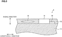
- FIG. 5 being an explanatory view schematically illustrating a partly cross-sectional structure when one example of a plated steel wire 3 according to a comparative example is taken along a longitudinal direction of a steel wire 11, when lengths along a longitudinal direction in a cross section in the longitudinal direction of the steel wire 11, of intermetallic compounds 15 present in a plating film layer 13, are each longer than a predetermined length, the intermetallic compounds 15 cannot sufficiently follow an elongation of the base steel wire 11 at a time of wire drawing of the plated steel wire 3, so that a crack is made to occur in the plating film layer 13.
- the present inventors have conceived based on the above appreciation that in Zn alloy plating capable of forming a plating film by using the electroplating capable of making the plating film thickness small, and excellent in corrosion resistance of the plating film layer while suppressing corrosion of the base steel wire, suppressing the presence of the intermetallic compound is effective for suppressing occurrence of corrosion of the steel wire and progress thereof even though the plating film thickness is made small.
- the present invention as follows has been achieved.
- a summary of the present invention is as follows.
- the plating film layer can be formed by electroplating, so that the plating film thickness can be made small, resulting in not causing a weight increase of a plated steel wire due to the plating film layer.
- no presence of an intermetallic compound in such a state that a length along a longitudinal direction in a cross section in the longitudinal direction of the steel wire, of the intermetallic compound present in the plating film layer, is longer than a predetermined length makes it possible to suppress peeling or cracking of the plating film layer at a time of processing to a thin wire of the plated steel wire, and also suppress a fatigue fracture caused by these.
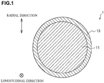
- FIG. 1 is an explanatory view schematically illustrating a cross-sectional structure when one example of the plated steel wire 1 according to this embodiment is taken along a radial direction of a steel wire 11
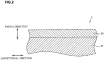
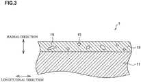
- FIG. 2 and FIG. 3 are explanatory views each schematically illustrating a partly cross-sectional structure when one example of the plated steel wire 1 according to this embodiment is taken along a longitudinal direction of the steel wire 11.
- the plated steel wire 1 is the plated steel wire (for example, an ultrathin plated steel wire) 1 provided with an alloy plating film layer 13 composed of a predetermined alloy on a surface of the steel wire (for example, an ultrathin steel wire or the like) 11.
- the drawings illustrated in FIG. 1 to FIG. 3 do not illustrate roughness likely to be present on the surface of the steel wire 11 for convenience of drawing creation.
- a wire rod having a tensile strength of 1000 MPa or more is preferably used, and a wire rod having a tensile strength of 2800 MPa or more is more preferably used.
- the plated steel wire steel cord
- the plated steel wire can be preferably used as, for example, a reinforcing material to reinforce rubber of the above-mentioned tire, conveyor, and the like.
- an upper limit of the tensile strength of the steel wire 11 is not particularly limited, and preferably as high as possible.
- the tensile strength of the steel wire 11 can be measured by a tensile test compliant with JIS Z2241 (1998). Further, in a case of the steel cord, tensile strength can be measured by a tensile test compliant with JIS G3510 (1992).
- the steel wire 11 having the above-described tensile strength there can be cited a high-carbon steel wire in which the content of carbon is approximately 0.8 mass% or more.
- a wire diameter of such a steel wire 11 is not particularly limited, but for example, the wire diameter (diameter) is about 0.05 mm to 0.4 mm.
- the plating film layer 13 is located on the surface of the steel wire 11 as illustrated in FIG. 1 and FIG. 2 , and includes at least any element selected from an element group constituted of Co, Cr, Cu, Ni, P, Sn, Mn and Fe, and Zn. Further, the plating film layer 13 may include impurities.
- the impurities are not the ones intentionally added as components of the plating film layer 13, but the ones mixed in a raw material or in a manufacturing process, and there can be cited Al, Mg, Si, Ti, B, S, N, C, Nb, Pb, Cd, Ca, Y, La, Ce, Sr, Sb, O, F, Cl, Zr, Ag, W and so on. Even though the impurities are present up to about 1 mass% in total relative to the mass of the entire plating film layer 13, such an effect to be obtained by the plating film layer 13 as explained below is not impaired.
- a natural immersion potential at 35°C of the plating film layer 13 according to this embodiment is more electronegative than -0.5 V vs.NHE.
- the natural immersion potential at 35°C of the plating film layer 13 is more electropositive than -0.5 V vs.NHE, too small potential difference between the steel and the plating film layer makes exhibition of sacrificial anticorrosive ability by the plating film layer 13 difficult, and the steel wire 11 corrodes.
- the natural immersion potential at 35°C of the plating film layer 13 is preferably -0.5 V vs.NHE.
- the natural immersion potential at 35°C of the plating film layer 13 is more preferably set to -0.6 V vs.NHE or less, and further preferably set to -0.7 V vs.NHE or less, and thus, the corrosion of the steel wire 11 can be suppressed more. Further, from the viewpoints of workability and corrosion fatigue in the plated steel wire 1, the natural immersion potential at 35°C of the plating film layer 13 is preferably -0.8 V vs.NHE or more.
- the natural immersion potential at 35°C of the plating film layer 13 is more preferably set to -0.78 V vs.NHE or more, and further preferably set to -0.77 V vs.NHE or more, and thus, the workability in the plated steel wire 1 can be increased more, and the corrosion fatigue can be avoided more.
- the natural immersion potential of the steel wire 11 or the plating film layer 13 can be confirmed by reading a potential when they are each immersed in a 3.0 mass% NaCl solution air-saturated under an environment of 35°C, for 60 seconds. Further, in a case of a rubber-plated steel wire composite in which the plated steel wire 1 or the steel cord including the plated steel wire 1 is embedded in rubber, measurement can be performed by dissolving and removing the rubber with a solvent capable of dissolving rubber, such as N-methyl-pyrrolidinone, and exposing the plated steel wire 1. Note that when some treatment is performed on an upper layer of the above-described plating film layer 13 in order to further improve adhesiveness between the plated steel wire 1 and the rubber, measurement is desirably performed after removing the above treatment layers.
- the plating film layer 13 may include intermetallic compounds 15 each composed of at least any element selected from the above-described element group (Co, Cr, Cu, Ni, P, Sn, Mn and Fe), and Zn, as illustrated in FIG. 3 , and the plating film layer 13 does not preferably include the above-described intermetallic compound 15, as illustrated in FIG. 2 . Further, when the plating film layer 13 includes the above-described intermetallic compound 15, a length along a longitudinal direction in a cross section in the longitudinal direction of the steel wire 11, of the intermetallic compound 15, is set to 1 ⁇ m or less.
- the intermetallic compound 15 is not continuously present up to 1 ⁇ m or more along the longitudinal direction in a layered shape or in a particulate shape in the plating film layer 13.
- the continuous presence of the intermetallic compounds indicates that without the presence of a phase other than an intermetallic compound phase, such as a pure metal phase, between the intermetallic compounds, one or a plurality of intermetallic compounds are present up to 1 ⁇ m or more along a longitudinal direction in a cross section in the longitudinal direction of the steel wire 11. Note that at this time, a case where a plurality of intermetallic compounds are adjacently present is also regarded as continuity.
- phase of the intermetallic compound there can be exemplified a ⁇ 2 phase, a ⁇ 1 phase, a ⁇ phase, and a ⁇ 1 phase of Zn-Co, a ⁇ phase of Zn-Cr, a ⁇ phase, a ⁇ ' phase, a ⁇ phase, and an ⁇ phase of Zn-Cu, a ⁇ phase, a ⁇ phase, a ⁇ 1 phase, and a ⁇ phase of Zn-Ni, a Zn 3 P 2 phase and a ZnP 2 phase of Zn-P, a ⁇ phase, a ⁇ phase, a ⁇ 1 phase, a ⁇ phase, and an ⁇ phase of Zn-Mn, a ⁇ phase, a ⁇ 1 phase, a ⁇ phase, and a ⁇ 1 phase of Zn-Fe, and so on, illustrated in phase diagrams.
- a ternary alloy phase or the like may also be included.
- an alloy of the element included in the plating film layer 13 and Fe included in the steel wire 11 is sometimes formed, but the here described intermetallic compound does not include such an alloy of the element and Fe included in the steel wire 11. Note that such a Fe alloy is present in an interface between the steel wire 11 and the plating film layer 13.
- the intermetallic compound 15 is hard and poor in deformability, and therefore, when such an intermetallic compound is continuously present longer than 1 ⁇ m in the plating film layer 13, the intermetallic compound 15 cannot follow deformation of steel at the occasion of hard working such as wire drawing until the steel wire 11 comes to have a small diameter, thereby resulting in occurrence of cracking or a crack at a present location of the intermetallic compound 15 in the plating film layer 13.
- the intermetallic compound 15 in order to suppress the occurrence of such cracking or a crack, is not made continuously present in a layered shape or in a particulate shape in the plating film layer 13.
- a length along a longitudinal direction in a cross section in the longitudinal direction of the steel wire 11, of the intermetallic compound 15, is preferable to be as small as possible, preferably set to 0.1 ⁇ m or less, and more preferably set to 0.02 ⁇ m or less.
- the intermetallic compound 15 is not present in the plating film layer 13.
- measurement of the presence/absence of the above-described intermetallic compound 15 in the plating film layer 13 can be performed by a cross-section observation using a FE-SEM-EDX (a field-emission scanning electron microscope with energy dispersive X-ray analyzer) after cutting a cross-section sample with a Cryo CP (Cross section Polisher) being a device in which the plating film layer 13 is difficult to damage due to heat.
- FE-SEM-EDX a field-emission scanning electron microscope with energy dispersive X-ray analyzer
- Whether the intermetallic compound 15 is continuously present in the plating film layer 13 can be distinguished by producing a sample cross section with the above-mentioned Cryo CP, performing elemental analysis with the FE-SEM-EDX, and performing a comparison with compositions of intermetallic compound phases illustrated in the phase diagrams. Moreover, a length of the intermetallic compound distinguished in such a manner can be obtained from an image of the sample cross section.
- the plating film layer 13 includes one element selected from an element group (Co, Cr, Cu, Ni, P, Mn and Fe), in the plating film layer 13, it is preferable that Co is not less than 0.1 mass% nor more than 6 mass%, Cr is not less than 0.1 mass% nor more than 5 mass%, Cu is not less than 0.1 mass% nor more than 13 mass%, Ni is not less than 0.1 mass% nor more than 9 mass%, P is not less than 0.1 mass% nor more than 24 mass%, Mn is not less than 0.1 mass% nor more than 5 mass%, and Fe is not less than 0.1 mass% nor more than 5 mass%.
- Co is not less than 0.1 mass% nor more than 6 mass%
- Cr is not less than 0.1 mass% nor more than 5 mass%
- Cu is not less than 0.1 mass% nor more than 13 mass%
- Ni is not less than 0.1 mass% nor more than 9 mass%
- P is not less than 0.1 mass% nor more than 24 mass%
- Mn is not less than 0.1 mass% nor
- Co is more preferably 0.3 mass% or more, further preferably 0.5 mass% or more, more preferably 4 mass% or less, and further preferably 3 mass% or less.
- Cr is more preferably 0.5 mass% or more, further preferably 1.0 mass% or more, more preferably 4 mass% or less, and further preferably 3 mass% or less.
- Cu is more preferably 1 mass% or more, further preferably 3 mass% or more, more preferably 12 mass% or less, and further preferably 9 mass% or less.
- Ni is more preferably 0.5 mass% or more, further preferably 1 mass% or more, more preferably 5 mass% or less, and further preferably 4 mass% or less.
- P is more preferably 1 mass% or more, further preferably 3 mass% or more, more preferably 13 mass% or less, and further preferably 9 mass% or less.
- Mn is more preferably 0.3 mass% or more, further preferably 1 mass% or more, more preferably 4 mass% or less, and further preferably 2 mass% or less.
- Fe is more preferably 0.3 mass% or more, further preferably 0.7 mass% or more, more preferably 4 mass% or less, and further preferably 3 mass% or less.
- the plating film layer 13 when the plating film layer 13 according to this embodiment includes Sn, in the plating film layer 13, Sn is preferably set to not less than 0.1 mass% nor more than 40 mass%.
- the natural immersion potential at 35°C can be set to -0.5 V vs.NHE or less, and moreover, it is possible to achieve both the corrosion protection of the steel wire 11 and the suppression of corrosion of the plating film layer 13 even though the thickness of the plating film layer 13 is small.
- Sn contained in the plating film layer 13 is more preferably 1 mass% or more, further preferably 3 mass% or more, more preferably 35 mass% or less, and further preferably 15 mass% or less.
- the plating film layer 13 when the plating film layer 13 according to this embodiment includes two or more elements selected from the element group (Co, Cr, Cu, Ni, P, Mn and Fe), the plating film layer 13 preferably includes the above-described elements so that M represented in the following formula (1) is not less than 0 nor more than 6.
- the plating film layer 13 more preferably includes the above-described elements so that M represented in the following formula (1) is not less than 0 nor more than 3.
- M M Co + M Cr + M Cu / 2 + M Ni / 1.5 + M P / 4 + M Mn + M Fe
- M(Co) is the content (mass%) of Co included in the film layer
- M(Cr) is the content (mass%) of Cr included in the film layer
- M(Cu) is the content (mass%) of Cu included in the film layer
- M(Ni) is the content (mass%) of Ni included in the film layer
- M(P) is the content (mass%) of P included in the film layer
- M(Mn) is the content (mass%) of Mn included in the film layer
- M(Fe) is the content (mass%) of Fe included in the film layer.
- the content of Zn included in the film layer 13 is not particularly limited as long as the natural immersion potential at 35°C of the film layer 13 is more electronegative than -0.5 Vvs.NHE, and the intermetallic compound which is composed of at least any element selected from the element group (Co, Cr, Cu, Ni, P, Mn and Fe), and Zn, and whose length along the longitudinal direction of the steel wire 11 exceeds 1 ⁇ m is not included.
- the content (mass%) of Zn is the largest of the elements included in the film layer 13, and may be, for example, 50% or more, 60% or more, 65% or more, 70% or more, or 80% or more.
- An average thickness in a circumferential direction of the steel wire 11 in the plated steel wire 1, of the plating film layer 13 according to this embodiment is 0.02 ⁇ m or more.
- an upper limit of the above-described thickness of the plating film layer 13 is not particularly limited, but preferably set to 4.0 ⁇ m or less in order to suppress a weight of the entire plated steel wire 1.
- the above-described thickness of the plating film layer 13 is more preferably set to not less than 0.1 ⁇ m nor more than 3.0 ⁇ m, and further preferably set to not less than 0.2 ⁇ m nor more than 1.2 ⁇ m. Note that when the heat treatment is performed in order to remove the stress in electrodeposits present in the plating film layer 13, the alloy of the element included in the plating film layer 13 and Fe included in the steel wire 11 is sometimes formed, and such a Fe alloy layer is included in the thickness of the plating film layer 13.
- a base plating layer (whose illustration is omitted) is provided between the steel wire 11 and the plating film layer 13 to form an alloy of an element included in the base plating layer or Fe included in the steel wire 11, and the element included in the plating film layer 13, such an alloy layer is included in the thickness of the plating film layer 13.
- a defect or a flaw such as a crack or a pinhole may be present.
- a composition of the plating film layer 13 after being embedded in rubber can be measured by producing a C cross section with the device in which the plating film layer 13 is difficult to damage, such as the Cryo CP, and performing elemental analysis with the FE-SEM-EDX, a FE-EPMA, or a TEM-EDS. Further, the thickness of the plating film layer 13 can be obtained by measuring thicknesses of the largest portion and the smallest portion on the circumference of the obtained cross section and averaging them.
- a plurality of the above-mentioned plated steel wires 1 are preferably twisted to form a steel cord when embedded in rubber. Twisting the plurality of plated steel wires 1 makes it possible to increase strength, and further provide toughness with respect to deflection or deformability, as compared with a case of using the single plated steel wire 1. Further, in the above-described steel cord, without being limited to twisting a plurality of the above-mentioned plated steel wires 1, the twisting may be performed so as to dispose the above-described plated steel wires 1 in the outer peripheral portion of the steel cord more likely to corrode and dispose other steel wires in the central portion of the steel cord. Thus, it is possible to obtain the steel cord being unlikely to corrode and having high strength.
- a rubber-plated steel wire composite provided with desired capability can be obtained by embedding the above-mentioned plated steel wire 1 or the steel cord formed by twisting the plated steel wires 1 in a rubber composition.
- the above-mentioned steel cord is sandwiched in sheet-shaped rubber obtained by kneading a raw material compounding the rubber composition and carbon black, sulfur, zinc oxide, and other various additives, to be formed as a reinforcing belt structure.
- the one formed as a green tire by laminating tire composing members is set, pressed, and heated in a vulcanizer, and the rubber and the plated steel wires are bonded to each other simultaneously with crosslinking for exhibiting strength of the rubber. This makes it possible to manufacture such a rubber-plated steel wire composite as represented by the tire.
- the kind of the rubber composition in which the above-mentioned plated steel wire 1 or the above-mentioned steel cord is embedded is not particularly limited, and for example, in general, well-known natural rubber or synthetic rubber can be used independently, or two or more of them can be mixed to be used.
- the synthetic rubber for example, there can be used diene-based rubber such as butadiene rubber, styrene-butadiene rubber, isoprene rubber, chloroprene rubber, or acrylonitrile-butadiene rubber, olefin-based rubber such as butyl rubber, ethylene-propylene rubber, ethylene-vinyl acetate rubber, chlorosulfonated polyethylene, or acrylic rubber, urethane rubber, fluororubber, polysulfide rubber, or the like.
- diene-based rubber such as butadiene rubber, styrene-butadiene rubber, isoprene rubber, chloroprene rubber, or acrylonitrile-butadiene rubber
- olefin-based rubber such as butyl rubber, ethylene-propylene rubber, ethylene-vinyl acetate rubber, chlorosulfonated polyethylene, or acrylic rubber, urethane rubber, fluororubber, polys
- a compounding agent to be normally used in rubber industry for improving and adjusting capability of rubber can be compounded appropriately with a normal compounding amount.
- the compounding agent for example, there can be cited a filler such as carbon black or silica, a softening agent such as an aroma oil, vulcanization accelerators such as guanidines such as diphenylguanidine, thiazoles such as mercaptobenzothiazole, sulfenamides such as N,N'-dicyclohexyl-2-benzothiazolylsulfenamide, or thiurams such as tetramethylthiuram disulfide, a vulcanization supplement accelerator such as zinc oxide, an antioxidant such as amines such as poly(2,2,4-trimethyl-1,2-dihydroquinoline) or phenyl- ⁇ -naphthylamine, or the like. Note that in this embodiment, even when such a compound
- a film for further improving corrosion resistance and wire drawability, or another film for improving adhesiveness between the plated steel wire 1 or the steel cord and the rubber may be present.
- a film having a desired property but for example, there can be cited a Cu film, a Sn film, a Cr film and an alloy thereof, or a phosphate film, a chromate film, a silane coupling agent, an organic resin film, or the like.
- other well-known films can also be applied.
- a resin component of the above-described organic resin film for example, there is usable an epoxy-based resin, a urethane-based resin, a polyester-based resin, a phenol-based resin, a polyethersulfone-based resin, a melamine-alkyd-based resin, an acryl-based resin, a polyamide-based resin, a polyimide-based resin, a silicone-based resin, a polyvinyl acetate-based resin, a polyolefin-based resin, a polystyrene-based resin, a vinyl chloride-based resin, a vinyl acetate-based resin, a natural rubber resin, a synthetic rubber resin, or the like.
- a silanol group or the like may be introduced to the above-described various resins. Further, for formation of a resin layer, these resins may be used independently, a mixture of these resins may be used, or a laminated structure of these resins may be formed. Moreover, in order to improve properties of these resins, a pigment or the like may be included.
- the composition and the natural immersion potential of the plating film layer 13 are specified as mentioned above.
- the intermetallic compound 15 is not made present in such a state that a length along a longitudinal direction in a cross section in the longitudinal direction of the steel wire 11, of the intermetallic compound 15 present in the plating film layer 13, is longer than a predetermined length.
- FIG. 4 is an explanatory diagram schematically illustrating one example of a manufacturing process of the plated steel wire 1 and the steel cord according to this embodiment.
- a steel wire rod having a diameter of 5.5 mm is manufactured by hot rolling. Moreover, after pickling the obtained steel wire rod and removing scale (descaling), the steel wire rod having a diameter of 5.5 mm is formed as the one having a diameter of 1.0 to 1.8 mm by dry drawing to be wound in a coil shape.
- the above-mentioned plating film layer 13 is formed on a surface of the pickled steel wire.
- an already-known electroplating method can be used. There can be used a sulfuric acid bath, a chloride bath, a cyanide bath, a pyrophosphate bath, a boric acid bath, a citric acid bath, other complex baths, and a combination of these, and so on as an electroplating bath.
- the plating film layer 13 including a desired amount of Co, Cr, Cu, Ni, P, Sn, Mn and Fe can be formed by adding one or more single ions or complex ions selected from Co, Cr, Cu, Ni, P, Sn, Mn and Fe besides Zn ions to the plating bath. Further, in order to control stabilization of the ions in the plating bath and properties of the plating, an additive is further preferably added to the above-described plating bath.
- a composition, a temperature and a flow velocity of the above-described electroplating bath, and a current density, an energization pattern, and the like at a time of the plating may be appropriately selected so as to cause a desired plating composition, and are not particularly limited. Further, a thickness of the plating film layer 13 can be controlled by adjusting a current value and a time within a range of the current density causing the desired composition.
- heat treatment may be performed in order to remove stress in electrodeposits in the plating film layer 13 and improve workability at a time of wet drawing.
- a temperature is preferably 250°C to 400°C, and further preferably 250°C to 350°C.
- a time of holding at temperatures of 250°C or higher is suitably shorter than 30 seconds, preferably shorter than 15 seconds, and more preferably shorter than 10 seconds.
- the plated steel wire subjected to such electroplating treatment is wound in a coil shape again. Thereafter, while the plated steel wire wound in a coil shape is unwound, it is subjected to the wet drawing using a wet lubricant to obtain the plated steel wire 1 having desired wire diameter and strength, for example, having a diameter of 0.1 to 0.4 mm.
- the formation of the above-described plating film layer 13 may be performed after the wet drawing. However, in order to avoid strength decrease of the steel wire, the heat treatment is not preferably performed after the wet drawing.
- a Cu film, a Sn film, a Cr film and an alloy film thereof, or an organic resin film or the like may be formed on a further upper layer of the plating film layer 13, and in this case, already-known methods can be used as forming methods of these upper layer films.
- the Cu film, the Sn film, the Cr film and the alloy film thereof can be formed by the electroplating method
- a phosphate film can be formed by immersion or a spray method
- a chromate film or a trivalent chromium-treated film can be formed by a coating method or an electrolytic method.
- a silane coupling treatment film, a urethane resin film, an epoxy resin film, or an acrylic resin film can be formed by the coating method or the like.
- the coating method is not particularly limited either, and the immersion method, the spray method, or the like can be used.
- the formation of the above-mentioned upper layer film is desirably performed after final wire drawing when such an upper layer film having low spreadability as the phosphate film, the chromate film, the trivalent chromium-treated film or resin is formed. Further, because brass plating (Cu-Zn) and Cu-Sn plating in the Cu alloy film have high spreadability and work as lubricating coating at the occasion of final wire drawing by a wet method, the formation of these upper layer films is desirably performed before the final wire drawing.
- the plated steel wire 1 obtained in the above-mentioned manner is provided for a wire twisting process.
- a plurality of the plated steel wires 1 are twisted at a predetermined pitch to be wound.
- the steel cord according to this embodiment can be obtained.
- the above-mentioned plated steel wire 1 or steel cord is covered with the rubber composition by a well-known method. Then, in order to improve strength of the rubber composition, the plated steel wire 1 or steel cord covered with the rubber composition is vulcanized at 170°C to 220°C for several minutes to several hours.
- a vulcanizing agent to be used for the vulcanization the well-known one can be used, and for example, there can be used the various ones such as sulfur and its congeneric elements (Se, Te), a sulfur-containing organic compound, an organic peroxide, a metal oxide (MgO, PbO, ZnO, or the like), organic polyvalent amine, a modified phenolic resin, or isocyanates.
- the vulcanization accelerator may be added.
- the rubber-plated steel wire composite according to this embodiment can be formed.
- the plated steel wire 1, the steel cord and the rubber-plated steel wire composite which make it possible to achieve both the corrosion protection of the base steel wire 11 and the suppression of corrosion of the plating film layer 13, and suppress the peeling of the rubber and the corrosion of the base steel wire 11 even though the thickness of the plating film layer 13 is small.
- the plated steel wire 1, the steel cord and the rubber-plated steel wire composite which make it possible to suppress the peeling or the cracking of the plating film layer 13 at the time of processing to a thin wire of the plated steel wire 1, and also suppress the fatigue fracture caused by these because the intermetallic compound whose length along a longitudinal direction in a cross section in the longitudinal direction of the steel wire 11 exceeds 1 ⁇ m cannot be made present in the plating film layer 13.
- a Zn plating film (Table 1 No. 1), Zn-Co plating films (Table 1 No. 3 to 7), Zn-Ni plating films (Table 1 No. 17 to 21), Zn-P plating films (Table 1 No. 22 to 27), Zn-Mn plating films (Table 1 No. 33 to 37), Zn-Fe plating films (Table 1 No. 38 to 42), Zn-Co-Ni plating films (Table 1 No. 43 to 44), Zn-Ni-P plating films (Table 1 No.
- a Zn-Ni-Fe-Co plating film (Table 1 No. 49) were formed by using plating baths obtained by adjusting concentrations and pHs of a zinc sulfate heptahydrate, a cobalt sulfate heptahydrate, a nickel sulfate hexahydrate, a sodium hypophosphite monohydrate, a manganese sulfate monohydrate, and an iron (II) sulfate heptahydrate so that average thicknesses of plating film layers and a Co concentration, a Ni concentration, a P concentration, a Mn concentration, and a Fe concentration in the plating films after wire drawing became thicknesses and concentrations in Table 1, and adjusting current density.
- Zn-Cr plating films (Table 1 No. 8 to 11) and Zn-Cr-Fe plating films (Table 1 No. 45 to 46) were formed by using plating baths obtained by adjusting concentrations and pHs of a zinc sulfate heptahydrate, a chromium (III) chloride hexahydrate, and an iron (II) sulfate heptahydrate so that average thicknesses of plating film layers and a Cr concentration and a Fe concentration in the plating films after the wire drawing became thicknesses and concentrations in Table 1, and adjusting current density.
- Zn-Cu plating films (Table 1 No. 2, 12 to 16) and Zn-Sn plating films (Table 1 No. 28 to 32) were formed by using plating baths obtained by adjusting concentrations and pHs of a zinc pyrophosphate trihydrate and a copper pyrophosphate tetrahydrate so that average thicknesses of plating film layers and a Cu concentration and a Sn concentration of the plating film layers after the wire drawing became thicknesses and concentrations in Table 1, and adjusting current density.
- the obtained steel wire was subjected continuously to electrolytic degreasing with the alkaline solution and electrolytic pickling with the sulfuric acid, and subjected to plating indicated in the following Table 2.
- Zn-Co-Fe plating films Table 2 No. 50 to 51, 62 to 63
- Zn-Cr-Fe plating films Table 2 No. 52 to 53, 64 to 65
- Zn-Cu-Fe plating films Table 2 No. 54 to 55, 66 to 67
- Zn-Ni-Fe plating films Table 2 No. 56 to 57, 68 to 69
- Zn-P-Fe plating films Table 2 No. 58 to 59, 70 to 71
- Zn-Sn-Fe plating films Table 2 No.
- an IH (Induction Heating) furnace was used, and holding for three seconds was performed at an output of 15 kW to increase temperature to 300°C, thereafter being allowed to cool.
- the obtained plated steel wires were each subjected to wire drawing by wet drawing using a wet lubricant so that a wire diameter became 0.1 to 0.4 mm, thereby manufacturing plated steel wires.
- compositions of the plating film layers, presence/absence and continuity of an intermetallic compound, and thicknesses of the plating film layers were obtained by taking samples from the plated steel wires and observing and measuring cross-section samples produced by a Cryo CP with a FE-SEM-EDX.
- Table 1 to Table 2 present the results. Note that regarding the samples, when the intermetallic compound was present in the plating film layers, a case where a length along a longitudinal direction in a cross section in the longitudinal direction of the steel wire, of the intermetallic compound, was 1 ⁇ m or less was judged as discontinuity, and a case where the length was more than 1 ⁇ m was judged as continuity.
- Wire drawability was evaluated by the number of fractures when the plated steel wire corresponding to 10 kg of each of the plated steel wires in which the above-mentioned plating film layers were formed on the steel wires each having a diameter of 1.8 mm was subjected to wet drawing in a standard pass schedule so as to become a diameter of 0.4 mm.
- the one capable of being subjected to the wire drawing without fracture was regarded as A
- the one subjected to one-time fracture was regarded as B
- the one subjected to two or more-time fractures was regarded as C
- the ones having B or more were regarded as acceptance.
- Table 1 to Table 2 present the results.
- the four plated steel wires were twisted at a 5 mm pitch to be formed as a steel cord, which was set in a die and embedded in a rubber composition presented in the following Table 3, and vulcanization was performed by hot pressing in which heating was performed at 160°C for 30 minutes, to produce evaluation samples.
- the one having a maximum pulling force of less than 60% of brass plating was evaluated as C, the one having a maximum pulling force of 60% or more and less than 100% of the brass plating was evaluated as B, the one having a maximum pulling force of 100% or more of the brass plating was evaluated as A, and the ones having B or more were regarded as acceptance.
- the adhesiveness after deterioration when a pulling force when the steel cord was pulled out of the rubber composition in the evaluation sample subjected to the cutting process after the deterioration process was measured, and the pulling force before the deterioration process was set to 100, the one having the pulling force after the deterioration process of less than 50 was regarded as C, the one having the pulling force after the deterioration process of 50 or more and less than 75 was regarded as B, the one having the pulling force after the deterioration process of 75 or more was regarded as A, and the ones having B or more were regarded as acceptance.
- the deterioration process was performed by holding the evaluation sample in a thermo-hygrostat at a relative humidity of 95% and a temperature of 80°C for 300 hr. Table 1 to Table 2 present the results.
- Corrosion fatigue was evaluated regarding each of the obtained plated steel wires by immersing an end of a curvature portion by 20 mm in a 0.1% NaCl aqueous solution based on a rotating bending fatigue test of a stress loading method, and performing a corrosion fatigue resistance test at the number of rotations of 3000 rpm.
- the evaluation of the corrosion fatigue in which the number of rotations until a fracture of a brass-plated plated steel wire occurred was set as a life, was indicated by an index when the life was set to 100, 100 or less were regarded as C, 101 to 130 were regarded as B, more than 130 were regarded as A, and B or more were regarded as acceptance.
- Table 1 to Table 2 present the results.
- TRADE NAME SEAST G-S STEARIC ACID: ADEKA FATTY ACID SA-400 ANTIOXIDANT: MANUFACTURED BY OUCHI SHINKO CHEMICAL INDUSTRIAL CO., LTD..
- TRADE NAME NOCRAC 810NA CROSSLINKING ACCELERATOR: OUCHI SHINKO CHEMICAL INDUSTRIAL CO., LTD.
- TRADE NAME NOCCELER CZ
- any of the comparative examples did not satisfy at least one of the wire drawability, the adhesiveness after deterioration, and the corrosion fatigue. That is, the plated steel wire, the steel cord including the plated steel wire, and the rubber-plated steel wire composite in which the plated steel wire or the steel cord was embedded in rubber according to the comparative examples also included a case where it was not possible to say that the wire drawability was good, and moreover, it cannot be said that any of them suppressed corrosion of the steel wire and progress of the corrosion, thereby making it possible to suppress a deterioration in adhesiveness to rubber and the corrosion fatigue.
Landscapes
- Chemical & Material Sciences (AREA)
- Engineering & Computer Science (AREA)
- Chemical Kinetics & Catalysis (AREA)
- Electrochemistry (AREA)
- Materials Engineering (AREA)
- Metallurgy (AREA)
- Organic Chemistry (AREA)
- Mechanical Engineering (AREA)
- Ropes Or Cables (AREA)
- Electroplating Methods And Accessories (AREA)
- Tires In General (AREA)
- Heat Treatment Of Steel (AREA)
Abstract
Description
- The present invention relates to a plated steel wire, a steel cord and a rubber-plated steel wire composite.
- This application is based upon and claims the benefit of priority of the prior Japanese Patent Application No.
2017-012448 - In general, in rubber products such as a tire and a conveyor, for the purpose of reinforcement thereof, there is used a steel cord (plated steel cord) obtained by twisting a plurality of steel wires whose surfaces are brass plated (copper-zinc alloy plated) and in which the surfaces of such brass-plating film layers are further covered with rubber, for example. As causes of shortening a life of these rubber products reinforced with the steel cord, there are corrosion of the steel wire and corrosion fatigue caused by the corrosion. The rubber to be used for the tire, the conveyor, and so on is penetrated by water and oxygen, and various additives are used for the rubber product in order to give the rubber desirable capability. Therefore, when the interior of the rubber product contains water, the steel wire is exposed to a corrosive environment, resulting in corrosion.
- Moreover, the rubber product is scratched by various external internal factors during use, and water easily infiltrates, whereby the corrosion of the steel wire is sometimes promoted. As a result, there has been a problem that the rubber peels from the steel cord with the corrosion, or the steel cord fractures earlier than its original fatigue life due to the corrosion fatigue, so that the life of the rubber product becomes shorter than the original fatigue life of the steel cord.
- As techniques of improving corrosion resistance of the steel wire, there have been proposed a technique of hot dipping with Zn having sacrificial anticorrosive ability with respect to a steel wire being a base material of a steel cord (for example, Patent Document 1), and a technique of hot dipping with a Zn-Al alloy (for example, Patent Document 2). As a further technique of suppressing the corrosion of the steel wire, for example, there has been proposed a technique of plating at least one steel wire located more closely to the interior than an outermost layer strand of the steel cord with Zn, Al, and Cr being metals each having a larger ionization tendency than iron (for example, Patent Document 3). Further, as a technique of improving corrosion resistance of a Zn-plating film layer given the steel wire, there has been proposed a technique of giving Zn plating in which particles of metals baser than Zn, such as Mg, Al, Ti, and Mn, have been dispersed, by electroplating (for example, Patent Document 4). Otherwise, as a technique of improving the corrosion resistance of a plating film layer by alloy plating, there has been proposed a technique of giving Zn-Ni alloy plating in which a Ni concentration of an uppermost surface layer portion of the plating film layer is set to 0 to 1 mass% and a Ni concentration of an innermost layer portion thereof is set to 5 to 20 mass% and whose composition is continuously changed (for example, Patent Document 5).
-
- Patent Document 1: Japanese Patent No.
4921879 - Patent Document 2: Japanese Laid-open Patent Publication No.
07-018590 - Patent Document 3: Japanese Laid-open Patent Publication No.
2015-196937 - Patent Document 4: Japanese Laid-open Patent Publication No.
2016-33235 - Patent Document 5: Japanese Laid-open Patent Publication No.
04-183893 - However, in the techniques proposed in the above-described
Patent Documents 1 to 2, there has been a problem that due to an adhesion amount of hot dipping with respect to the steel wire, the hot dipping makes it difficult to thin a plating film, and a weight of a plated steel wire is greatly increased by the plating, despite high improvement effect of the corrosion resistance of the steel wire. Thickening of the plating film not only increases costs at the occasion of the plating, but also, for example, in a case of using a steel cord composed of hot-dipped steel wires for reinforcing the tire, increases a weight of a tire due to a plating film thickness, resulting in a deterioration in fuel consumption of an automobile, and it is therefore not preferable that the plating film thickness becomes large. Further, in the technique proposed in the above-described Patent Document 3, Zn plating to make a plating film thickness small is poor in effect of corrosion resistance improvement of the steel wire, and on the other hand, in Zn plating to make a plating film thickness large, although the effect of corrosion resistance improvement of the steel wire is obtained, there exists a problem of causing a weight increase of a steel cord similarly to the above-mentioned hot dipping. Moreover, in the technique proposed in the above-described Patent Document 3, because Al and Cr form a strong passive film on a surface of the steel wire, it is difficult to exhibit the sacrificial anticorrosive ability with respect to the steel wire, resulting in poor effect of the corrosion resistance improvement of the steel wire. In addition, although the technique proposed in the above-described Patent Document 4 allows a plating film thickness to be made small by using the electroplating, and moreover, allows durability of Zn to be improved because Mg, Al, Ti, Mn, and so on dispersed in a Zn-plating film layer are more likely to melt than Zn, corrosion resistance of the entire plating film layer has not been sufficient. Moreover, although the technique proposed in the above-described Patent Document 5 suppresses peeling of a plating film from the steel wire at a time of wire drawing by continuously changing the composition of the plating film layer, a wire diameter after final wire drawing is 1 mm, and in a case of aiming at a further smaller diameter, the peeling of the plating film from the steel wire or cracking in the plating film layer occurs, and these each become a starting point of fatigue fracture due to corrosion of the steel wire. - That is, the conventional techniques have not made it possible to suppress occurrence of corrosion of the steel wire and progress thereof and sufficiently suppress peeling of rubber from the steel cord or corrosion fatigue while making a plating film thickness small.
- Thus, the present invention has been made in consideration of the above-described circumstances, and an object of the present invention is to provide a plated steel wire processable to a thin wire, a steel cord using the plated steel wires and a rubber-plated steel wire composite (rubber-steel cord composite), which allow a deterioration in adhesiveness to rubber and the corrosion fatigue to be suppressed by suppressing the occurrence of corrosion of the steel wire and the progress thereof even though the plating film thickness is made small.
- The present inventors have conducted a keen study regarding corrosion of a Zn-plated steel wire in order to solve the above-described problems. As a result, it has become clear that although the corrosion of the steel wire can be sufficiently suppressed by hot-dip Zn plating, insufficient corrosion resistance of a plating film itself is linked to early wear of the plating film, a deterioration in adhesiveness to rubber, and an early fracture of a steel cord due to progress of corrosion fatigue. While further conducting a keen study, the present inventors have known that when Zn alloy plating excellent in corrosion resistance of the plating film is given the steel wire by electroplating capable of making a plating film thickness small, a hard intermetallic compound is sometimes present in the electric Zn alloy plating film layer. The intermetallic compound cannot sufficiently follow an elongation of a base steel wire at a time of wire drawing of a plated steel wire due to poor plastic deformability, so that a crack occurs at a present location of the intermetallic compound in the plating film layer, and such a crack becomes a starting point of peeling of the plating film from the steel wire or fatigue fracture. In detail, as illustrated in
FIG. 5 being an explanatory view schematically illustrating a partly cross-sectional structure when one example of a plated steel wire 3 according to a comparative example is taken along a longitudinal direction of asteel wire 11, when lengths along a longitudinal direction in a cross section in the longitudinal direction of thesteel wire 11, ofintermetallic compounds 15 present in aplating film layer 13, are each longer than a predetermined length, theintermetallic compounds 15 cannot sufficiently follow an elongation of thebase steel wire 11 at a time of wire drawing of the plated steel wire 3, so that a crack is made to occur in theplating film layer 13. - Thus, the present inventors have conceived based on the above appreciation that in Zn alloy plating capable of forming a plating film by using the electroplating capable of making the plating film thickness small, and excellent in corrosion resistance of the plating film layer while suppressing corrosion of the base steel wire, suppressing the presence of the intermetallic compound is effective for suppressing occurrence of corrosion of the steel wire and progress thereof even though the plating film thickness is made small. As a result of putting a further keen study forward, the present invention as follows has been achieved. A summary of the present invention is as follows.
- [1] A plated steel wire including a film layer located on a surface of a steel wire and including at least any element selected from an element group constituted of Co, Cr, Cu, Ni, P, Sn, Mn and Fe, and Zn, wherein: a content of each of the elements selected from the element group in the film layer is 0.1 mass% or more; a natural immersion potential at 35°C of the film layer is more electronegative than -0.5 Vvs.NHE; and the film layer does not include an intermetallic compound composed of at least any element selected from the element group, and Zn, or when the film layer includes the intermetallic compound, a length along a longitudinal direction in a cross section in the longitudinal direction of the steel wire, of the intermetallic compound, is 1 µm or less.
- [2] The plated steel wire according to [1], wherein the film layer contains 6 mass% or less of Co.
- [3] The plated steel wire according to [1] or [2], wherein the film layer contains 5 mass% or less of Cr.
- [4] The plated steel wire according to any one of [1] to [3], wherein the film layer contains 13 mass% or less of Cu.
- [5] The plated steel wire according to any one of [1] to [4], wherein the film layer contains 9 mass% or less of Ni.
- [6] The plated steel wire according to any one of [1] to [5], wherein the film layer contains 24 mass% or less of P.
- [7] The plated steel wire according to any one of [1] to [6], wherein the film layer contains 40 mass% or less of Sn.
- [8] The plated steel wire according to any one of [1] to [7], wherein the film layer contains 5 mass% or less of Mn.
- [9] The plated steel wire according to any one of [1] to [8], wherein the film layer contains 5 mass% or less of Fe.
- [10] The plated steel wire according to any one of [1] to [9], wherein the film layer includes the elements so that M represented in a following formula (1) is 6 or less.

- [11] The plated steel wire according to [10], wherein the film layer includes the elements so that the M is not less than 0 nor more than 3.
- [12] The plated steel wire according to any one of [1] to [11], wherein a natural immersion potential at 35°C of the film layer is not less than -0.8 Vvs.NHE nor more than -0.6 Vvs.NHE.
- [13] The plated steel wire according to any one of [1] to [12], wherein an average thickness in a circumferential direction of the steel wire, of the film layer, is not less than 0.02 µm nor more than 4.0 µm.
- [14] A steel cord including the plated steel wire according to any one of [1] to [13].
- [15] A rubber-plated steel wire composite in which the plated steel wire according to any one of [1] to [13] and/or the steel cord according to [14] is/are embedded in rubber.
- According to the present invention as explained above, providing a Zn alloy plating film layer having sacrificial anticorrosive ability with respect to a steel wire and high corrosion resistance on a surface of the steel wire makes it possible to achieve both corrosion protection of a base steel wire and suppression of corrosion of the plating film layer even though a plating film thickness is small. As a result, according to the present invention, it is possible to suppress a deterioration in adhesiveness between a steel cord and rubber and suppress corrosion fatigue of the steel cord. Further, according to the present invention, the plating film layer can be formed by electroplating, so that the plating film thickness can be made small, resulting in not causing a weight increase of a plated steel wire due to the plating film layer. Moreover, according to the present invention, no presence of an intermetallic compound in such a state that a length along a longitudinal direction in a cross section in the longitudinal direction of the steel wire, of the intermetallic compound present in the plating film layer, is longer than a predetermined length makes it possible to suppress peeling or cracking of the plating film layer at a time of processing to a thin wire of the plated steel wire, and also suppress a fatigue fracture caused by these.
-
- [
FIG. 1] FIG. 1 is an explanatory view schematically illustrating a cross-sectional structure when one example of a platedsteel wire 1 according to an embodiment of the present invention is taken along a radial direction of asteel wire 11. - [
FIG. 2] FIG. 2 is an explanatory view schematically illustrating a partly cross-sectional structure when one example of the platedsteel wire 1 according to the same embodiment is taken along a longitudinal direction of thesteel wire 11. - [
FIG. 3] FIG. 3 is an explanatory view schematically illustrating a partly cross-sectional structure when another example of the platedsteel wire 1 according to the same embodiment is taken along the longitudinal direction of thesteel wire 11. - [
FIG. 4] FIG. 4 is an explanatory diagram schematically illustrating one example of a manufacturing process of theplated steel wire 1 according to the same embodiment. - [
FIG. 5] FIG. 5 is an explanatory view schematically illustrating a partly cross-sectional structure when one example of a plated steel wire 3 according to a comparative example is taken along a longitudinal direction of asteel wire 11. - A preferred embodiment of the present invention will be explained in detail with reference to accompanying drawings below. Note that the embodiment indicated below does not limit the present invention. Further, components of such an embodiment include the one in which a substitution is possible and easy for what is called those skilled in the art, or substantially the same one. Moreover, what is called those skilled in the art can arbitrarily combine various forms included in the following embodiment within an obvious range.
- Hereinafter, a plated
steel wire 1 according to the embodiment of the present invention will be explained in detail with reference toFIG. 1 to FIG. 3 .FIG. 1 is an explanatory view schematically illustrating a cross-sectional structure when one example of the platedsteel wire 1 according to this embodiment is taken along a radial direction of asteel wire 11, andFIG. 2 andFIG. 3 are explanatory views each schematically illustrating a partly cross-sectional structure when one example of the platedsteel wire 1 according to this embodiment is taken along a longitudinal direction of thesteel wire 11. - As schematically illustrated in
FIG. 1 to FIG. 3 , the platedsteel wire 1 according to this embodiment is the plated steel wire (for example, an ultrathin plated steel wire) 1 provided with an alloyplating film layer 13 composed of a predetermined alloy on a surface of the steel wire (for example, an ultrathin steel wire or the like) 11. Note that the drawings illustrated inFIG. 1 to FIG. 3 do not illustrate roughness likely to be present on the surface of thesteel wire 11 for convenience of drawing creation. - As the
steel wire 11 according to this embodiment, a wire rod having a tensile strength of 1000 MPa or more is preferably used, and a wire rod having a tensile strength of 2800 MPa or more is more preferably used. As long as the tensile strength is 1000 MPa, the plated steel wire (steel cord) can be preferably used as, for example, a reinforcing material to reinforce rubber of the above-mentioned tire, conveyor, and the like. Note that an upper limit of the tensile strength of thesteel wire 11 is not particularly limited, and preferably as high as possible. Here, the tensile strength of thesteel wire 11 can be measured by a tensile test compliant with JIS Z2241 (1998). Further, in a case of the steel cord, tensile strength can be measured by a tensile test compliant with JIS G3510 (1992). - As the
steel wire 11 having the above-described tensile strength, there can be cited a high-carbon steel wire in which the content of carbon is approximately 0.8 mass% or more. A wire diameter of such asteel wire 11 is not particularly limited, but for example, the wire diameter (diameter) is about 0.05 mm to 0.4 mm. - The
plating film layer 13 according to this embodiment is located on the surface of thesteel wire 11 as illustrated inFIG. 1 andFIG. 2 , and includes at least any element selected from an element group constituted of Co, Cr, Cu, Ni, P, Sn, Mn and Fe, and Zn. Further, theplating film layer 13 may include impurities. Here, the impurities are not the ones intentionally added as components of theplating film layer 13, but the ones mixed in a raw material or in a manufacturing process, and there can be cited Al, Mg, Si, Ti, B, S, N, C, Nb, Pb, Cd, Ca, Y, La, Ce, Sr, Sb, O, F, Cl, Zr, Ag, W and so on. Even though the impurities are present up to about 1 mass% in total relative to the mass of the entireplating film layer 13, such an effect to be obtained by theplating film layer 13 as explained below is not impaired. - By setting the content of each of the elements selected from the above-described element group (Co, Cr, Cu, Ni, P, Sn, Mn and Fe) included in the
plating film layer 13 to 0.1 mass% or more, corrosion resistance of theplating film layer 13 itself can be improved. Note that by setting the total content of the elements selected from the above-described element group in theplating film layer 13 to be larger than 0.5 mass%, the effect of corrosion resistance improvement of theplating film layer 13 can be further increased, and by setting to 1.0 mass% or more, the effect of corrosion resistance improvement of theplating film layer 13 can be extremely increased. - A natural immersion potential at 35°C of the
plating film layer 13 according to this embodiment is more electronegative than -0.5 V vs.NHE. In detail, when the natural immersion potential at 35°C of theplating film layer 13 is more electropositive than -0.5 V vs.NHE, too small potential difference between the steel and the plating film layer makes exhibition of sacrificial anticorrosive ability by theplating film layer 13 difficult, and thesteel wire 11 corrodes. Thus, in this embodiment, in order to suppress corrosion of thesteel wire 11, the natural immersion potential at 35°C of theplating film layer 13 is preferably -0.5 V vs.NHE. Moreover, the natural immersion potential at 35°C of theplating film layer 13 is more preferably set to -0.6 V vs.NHE or less, and further preferably set to -0.7 V vs.NHE or less, and thus, the corrosion of thesteel wire 11 can be suppressed more. Further, from the viewpoints of workability and corrosion fatigue in the platedsteel wire 1, the natural immersion potential at 35°C of theplating film layer 13 is preferably -0.8 V vs.NHE or more. Moreover, the natural immersion potential at 35°C of theplating film layer 13 is more preferably set to -0.78 V vs.NHE or more, and further preferably set to -0.77 V vs.NHE or more, and thus, the workability in the platedsteel wire 1 can be increased more, and the corrosion fatigue can be avoided more. - Note that the natural immersion potential of the
steel wire 11 or theplating film layer 13 can be confirmed by reading a potential when they are each immersed in a 3.0 mass% NaCl solution air-saturated under an environment of 35°C, for 60 seconds. Further, in a case of a rubber-plated steel wire composite in which the platedsteel wire 1 or the steel cord including the platedsteel wire 1 is embedded in rubber, measurement can be performed by dissolving and removing the rubber with a solvent capable of dissolving rubber, such as N-methyl-pyrrolidinone, and exposing the platedsteel wire 1. Note that when some treatment is performed on an upper layer of the above-describedplating film layer 13 in order to further improve adhesiveness between the platedsteel wire 1 and the rubber, measurement is desirably performed after removing the above treatment layers. - The
plating film layer 13 according to this embodiment may includeintermetallic compounds 15 each composed of at least any element selected from the above-described element group (Co, Cr, Cu, Ni, P, Sn, Mn and Fe), and Zn, as illustrated inFIG. 3 , and theplating film layer 13 does not preferably include the above-describedintermetallic compound 15, as illustrated inFIG. 2 . Further, when theplating film layer 13 includes the above-describedintermetallic compound 15, a length along a longitudinal direction in a cross section in the longitudinal direction of thesteel wire 11, of theintermetallic compound 15, is set to 1 µm or less. That is, in this embodiment, theintermetallic compound 15 is not continuously present up to 1 µm or more along the longitudinal direction in a layered shape or in a particulate shape in theplating film layer 13. Here, the continuous presence of the intermetallic compounds indicates that without the presence of a phase other than an intermetallic compound phase, such as a pure metal phase, between the intermetallic compounds, one or a plurality of intermetallic compounds are present up to 1 µm or more along a longitudinal direction in a cross section in the longitudinal direction of thesteel wire 11. Note that at this time, a case where a plurality of intermetallic compounds are adjacently present is also regarded as continuity. Here, as the phase of the intermetallic compound, there can be exemplified a γ2 phase, a γ1 phase, a γ phase, and a β1 phase of Zn-Co, a θ phase of Zn-Cr, a β phase, a β' phase, a γ phase, and an ε phase of Zn-Cu, a δ phase, a γ phase, a β1 phase, and a β phase of Zn-Ni, a Zn3P2 phase and a ZnP2 phase of Zn-P, a ζ phase, a δ phase, a δ1 phase, a γ phase, and an ε phase of Zn-Mn, a ζ phase, a δ1 phase, a Γ phase, and a Γ1 phase of Zn-Fe, and so on, illustrated in phase diagrams. Further, besides these, a ternary alloy phase or the like may also be included. Further, when heat treatment is performed in order to remove stress in electrodeposits present in theplating film layer 13, an alloy of the element included in theplating film layer 13 and Fe included in thesteel wire 11 is sometimes formed, but the here described intermetallic compound does not include such an alloy of the element and Fe included in thesteel wire 11. Note that such a Fe alloy is present in an interface between thesteel wire 11 and theplating film layer 13. - In this embodiment, no continuous presence of the
intermetallic compound 15 in the longitudinal direction of thesteel wire 11 in a layered shape or in a particulate shape in theplating film layer 13 makes it possible to suppress peeling or cracking of theplating film layer 13 when the platedsteel wire 1 is processed to a thin wire. In detail, theintermetallic compound 15 is hard and poor in deformability, and therefore, when such an intermetallic compound is continuously present longer than 1 µm in theplating film layer 13, theintermetallic compound 15 cannot follow deformation of steel at the occasion of hard working such as wire drawing until thesteel wire 11 comes to have a small diameter, thereby resulting in occurrence of cracking or a crack at a present location of theintermetallic compound 15 in theplating film layer 13. Accordingly, in this embodiment, in order to suppress the occurrence of such cracking or a crack, theintermetallic compound 15 is not made continuously present in a layered shape or in a particulate shape in theplating film layer 13. Note that in this embodiment, a length along a longitudinal direction in a cross section in the longitudinal direction of thesteel wire 11, of theintermetallic compound 15, is preferable to be as small as possible, preferably set to 0.1 µm or less, and more preferably set to 0.02 µm or less. Moreover, it is further preferable that theintermetallic compound 15 is not present in theplating film layer 13. - Note that measurement of the presence/absence of the above-described
intermetallic compound 15 in theplating film layer 13 can be performed by a cross-section observation using a FE-SEM-EDX (a field-emission scanning electron microscope with energy dispersive X-ray analyzer) after cutting a cross-section sample with a Cryo CP (Cross section Polisher) being a device in which theplating film layer 13 is difficult to damage due to heat. - Whether the
intermetallic compound 15 is continuously present in theplating film layer 13 can be distinguished by producing a sample cross section with the above-mentioned Cryo CP, performing elemental analysis with the FE-SEM-EDX, and performing a comparison with compositions of intermetallic compound phases illustrated in the phase diagrams. Moreover, a length of the intermetallic compound distinguished in such a manner can be obtained from an image of the sample cross section. - When the
plating film layer 13 according to this embodiment includes one element selected from an element group (Co, Cr, Cu, Ni, P, Mn and Fe), in theplating film layer 13, it is preferable that Co is not less than 0.1 mass% nor more than 6 mass%, Cr is not less than 0.1 mass% nor more than 5 mass%, Cu is not less than 0.1 mass% nor more than 13 mass%, Ni is not less than 0.1 mass% nor more than 9 mass%, P is not less than 0.1 mass% nor more than 24 mass%, Mn is not less than 0.1 mass% nor more than 5 mass%, and Fe is not less than 0.1 mass% nor more than 5 mass%. Thus, formation of theintermetallic compound 15 in theplating film layer 13 is made more difficult, and moreover, it is possible to achieve both corrosion protection of thesteel wire 11 and suppression of corrosion of theplating film layer 13 even though a thickness of theplating film layer 13 is small. In theplating film layer 13, Co is more preferably 0.3 mass% or more, further preferably 0.5 mass% or more, more preferably 4 mass% or less, and further preferably 3 mass% or less. Cr is more preferably 0.5 mass% or more, further preferably 1.0 mass% or more, more preferably 4 mass% or less, and further preferably 3 mass% or less. Cu is more preferably 1 mass% or more, further preferably 3 mass% or more, more preferably 12 mass% or less, and further preferably 9 mass% or less. Ni is more preferably 0.5 mass% or more, further preferably 1 mass% or more, more preferably 5 mass% or less, and further preferably 4 mass% or less. P is more preferably 1 mass% or more, further preferably 3 mass% or more, more preferably 13 mass% or less, and further preferably 9 mass% or less. Mn is more preferably 0.3 mass% or more, further preferably 1 mass% or more, more preferably 4 mass% or less, and further preferably 2 mass% or less. Fe is more preferably 0.3 mass% or more, further preferably 0.7 mass% or more, more preferably 4 mass% or less, and further preferably 3 mass% or less. - Moreover, when the
plating film layer 13 according to this embodiment includes Sn, in theplating film layer 13, Sn is preferably set to not less than 0.1 mass% nor more than 40 mass%. Thus, the natural immersion potential at 35°C can be set to -0.5 V vs.NHE or less, and moreover, it is possible to achieve both the corrosion protection of thesteel wire 11 and the suppression of corrosion of theplating film layer 13 even though the thickness of theplating film layer 13 is small. Note that Sn contained in theplating film layer 13 is more preferably 1 mass% or more, further preferably 3 mass% or more, more preferably 35 mass% or less, and further preferably 15 mass% or less. - Moreover, when the
plating film layer 13 according to this embodiment includes two or more elements selected from the element group (Co, Cr, Cu, Ni, P, Mn and Fe), theplating film layer 13 preferably includes the above-described elements so that M represented in the following formula (1) is not less than 0 nor more than 6. Thus, formation of theintermetallic compound 15 in theplating film layer 13 is made more difficult, and moreover, it is possible to achieve both the corrosion protection of thesteel wire 11 and the suppression of corrosion of theplating film layer 13 even though the thickness of theplating film layer 13 is small. Note that theplating film layer 13 more preferably includes the above-described elements so that M represented in the following formula (1) is not less than 0 nor more than 3.
- Note that the content of Zn included in the
film layer 13 is not particularly limited as long as the natural immersion potential at 35°C of thefilm layer 13 is more electronegative than -0.5 Vvs.NHE, and the intermetallic compound which is composed of at least any element selected from the element group (Co, Cr, Cu, Ni, P, Mn and Fe), and Zn, and whose length along the longitudinal direction of thesteel wire 11 exceeds 1 µm is not included. Normally, the content (mass%) of Zn is the largest of the elements included in thefilm layer 13, and may be, for example, 50% or more, 60% or more, 65% or more, 70% or more, or 80% or more. - An average thickness in a circumferential direction of the
steel wire 11 in the platedsteel wire 1, of theplating film layer 13 according to this embodiment, is 0.02 µm or more. By setting such a plating film thickness, thebase steel wire 11 can be effectively protected from corrosion, and suppression of the corrosion fatigue caused by corrosion can be effectively attained. In this embodiment, an upper limit of the above-described thickness of theplating film layer 13 is not particularly limited, but preferably set to 4.0 µm or less in order to suppress a weight of the entire platedsteel wire 1. Note that the above-described thickness of theplating film layer 13 is more preferably set to not less than 0.1 µm nor more than 3.0 µm, and further preferably set to not less than 0.2 µm nor more than 1.2 µm. Note that when the heat treatment is performed in order to remove the stress in electrodeposits present in theplating film layer 13, the alloy of the element included in theplating film layer 13 and Fe included in thesteel wire 11 is sometimes formed, and such a Fe alloy layer is included in the thickness of theplating film layer 13. Moreover, when a base plating layer (whose illustration is omitted) is provided between thesteel wire 11 and theplating film layer 13 to form an alloy of an element included in the base plating layer or Fe included in thesteel wire 11, and the element included in theplating film layer 13, such an alloy layer is included in the thickness of theplating film layer 13. Further, in theplating film layer 13 according to this embodiment, a defect or a flaw such as a crack or a pinhole may be present. - A composition of the
plating film layer 13 after being embedded in rubber can be measured by producing a C cross section with the device in which theplating film layer 13 is difficult to damage, such as the Cryo CP, and performing elemental analysis with the FE-SEM-EDX, a FE-EPMA, or a TEM-EDS. Further, the thickness of theplating film layer 13 can be obtained by measuring thicknesses of the largest portion and the smallest portion on the circumference of the obtained cross section and averaging them. - A plurality of the above-mentioned plated
steel wires 1 are preferably twisted to form a steel cord when embedded in rubber. Twisting the plurality of platedsteel wires 1 makes it possible to increase strength, and further provide toughness with respect to deflection or deformability, as compared with a case of using the single platedsteel wire 1. Further, in the above-described steel cord, without being limited to twisting a plurality of the above-mentioned platedsteel wires 1, the twisting may be performed so as to dispose the above-described platedsteel wires 1 in the outer peripheral portion of the steel cord more likely to corrode and dispose other steel wires in the central portion of the steel cord. Thus, it is possible to obtain the steel cord being unlikely to corrode and having high strength. - A rubber-plated steel wire composite provided with desired capability can be obtained by embedding the above-mentioned plated
steel wire 1 or the steel cord formed by twisting the platedsteel wires 1 in a rubber composition. In detail, the above-mentioned steel cord is sandwiched in sheet-shaped rubber obtained by kneading a raw material compounding the rubber composition and carbon black, sulfur, zinc oxide, and other various additives, to be formed as a reinforcing belt structure. Thereafter, the one formed as a green tire by laminating tire composing members is set, pressed, and heated in a vulcanizer, and the rubber and the plated steel wires are bonded to each other simultaneously with crosslinking for exhibiting strength of the rubber. This makes it possible to manufacture such a rubber-plated steel wire composite as represented by the tire. - The kind of the rubber composition in which the above-mentioned plated
steel wire 1 or the above-mentioned steel cord is embedded is not particularly limited, and for example, in general, well-known natural rubber or synthetic rubber can be used independently, or two or more of them can be mixed to be used. As the synthetic rubber, for example, there can be used diene-based rubber such as butadiene rubber, styrene-butadiene rubber, isoprene rubber, chloroprene rubber, or acrylonitrile-butadiene rubber, olefin-based rubber such as butyl rubber, ethylene-propylene rubber, ethylene-vinyl acetate rubber, chlorosulfonated polyethylene, or acrylic rubber, urethane rubber, fluororubber, polysulfide rubber, or the like. - Further, in the above-described rubber composition, a compounding agent to be normally used in rubber industry for improving and adjusting capability of rubber can be compounded appropriately with a normal compounding amount. Specifically, as the compounding agent, for example, there can be cited a filler such as carbon black or silica, a softening agent such as an aroma oil, vulcanization accelerators such as guanidines such as diphenylguanidine, thiazoles such as mercaptobenzothiazole, sulfenamides such as N,N'-dicyclohexyl-2-benzothiazolylsulfenamide, or thiurams such as tetramethylthiuram disulfide, a vulcanization supplement accelerator such as zinc oxide, an antioxidant such as amines such as poly(2,2,4-trimethyl-1,2-dihydroquinoline) or phenyl-α-naphthylamine, or the like. Note that in this embodiment, even when such a compounding agent to be normally used in the rubber industry coexists in the rubber, it is possible to achieve both the corrosion protection of the
steel wire 11 and the suppression of corrosion of theplating film layer 13. - Moreover, in the above-mentioned plated
steel wire 1 or the above-mentioned steel cord, between theplating film layer 13 and the rubber, another film for further improving corrosion resistance and wire drawability, or another film for improving adhesiveness between the platedsteel wire 1 or the steel cord and the rubber may be present. Such a film is not particularly limited if a film having a desired property, but for example, there can be cited a Cu film, a Sn film, a Cr film and an alloy thereof, or a phosphate film, a chromate film, a silane coupling agent, an organic resin film, or the like. Further, without being limited to these, other well-known films can also be applied. In addition, as necessary, it is also possible to apply a multilayer film obtained by combining two or more of the above-mentioned films. - As a resin component of the above-described organic resin film, for example, there is usable an epoxy-based resin, a urethane-based resin, a polyester-based resin, a phenol-based resin, a polyethersulfone-based resin, a melamine-alkyd-based resin, an acryl-based resin, a polyamide-based resin, a polyimide-based resin, a silicone-based resin, a polyvinyl acetate-based resin, a polyolefin-based resin, a polystyrene-based resin, a vinyl chloride-based resin, a vinyl acetate-based resin, a natural rubber resin, a synthetic rubber resin, or the like. At this time, in order to improve adhesiveness to the
plating film layer 13 or the like, a silanol group or the like may be introduced to the above-described various resins. Further, for formation of a resin layer, these resins may be used independently, a mixture of these resins may be used, or a laminated structure of these resins may be formed. Moreover, in order to improve properties of these resins, a pigment or the like may be included. - As indicated above, in the plated
steel wire 1, the steel cord obtained by twisting the platedsteel wires 1, and the rubber-plated steel wire composite in which the platedsteel wire 1 or the steel cord is embedded according to the embodiment of the present invention, in order to achieve both the corrosion protection of thebase steel wire 11 and the suppression of corrosion of theplating film layer 13, and suppress peeling of the rubber and corrosion of thebase steel wire 11 even though the thickness of theplating film layer 13 is small, the composition and the natural immersion potential of theplating film layer 13 are specified as mentioned above. As a result, according to the embodiment of the present invention, it is possible to achieve suppression of a deterioration in adhesiveness between the platedsteel wire 1 or the steel cord and the rubber, and suppression of corrosion fatigue of the platedsteel wire 1 or the steel cord. Moreover, in the embodiment of the present invention, theintermetallic compound 15 is not made present in such a state that a length along a longitudinal direction in a cross section in the longitudinal direction of thesteel wire 11, of theintermetallic compound 15 present in theplating film layer 13, is longer than a predetermined length. As a result, according to the embodiment of the present invention, it is possible to suppress peeling or cracking of theplating film layer 13 at a time of processing to a thin wire of the platedsteel wire 1, and also suppress a fatigue fracture caused by these. - The above has explained constitutions of the plated
steel wire 1, the steel cord and the rubber-plated steel wire composite according to a preferred embodiment of the present invention in detail, and successively, a manufacturing method of the platedsteel wire 1, the steel cord and the rubber-plated steel wire composite will be explained with reference toFIG. 4. FIG. 4 is an explanatory diagram schematically illustrating one example of a manufacturing process of the platedsteel wire 1 and the steel cord according to this embodiment. - For example, a steel wire rod having a diameter of 5.5 mm is manufactured by hot rolling. Moreover, after pickling the obtained steel wire rod and removing scale (descaling), the steel wire rod having a diameter of 5.5 mm is formed as the one having a diameter of 1.0 to 1.8 mm by dry drawing to be wound in a coil shape.
- Then, while the steel wire wound in a coil shape is unwound, it is subjected to material adjustment by performing final heat treatment at 800 to 900°C and cooling (what is called, patenting treatment) in order to obtain a uniform and fine pearlite structure. Thereafter, electrolytic degreasing with an alkaline solution and electrolytic pickling with acid using hydrochloric acid, sulfuric acid, or the like are performed.
- Next, the above-mentioned
plating film layer 13 is formed on a surface of the pickled steel wire. As a forming method of theplating film layer 13, an already-known electroplating method can be used. There can be used a sulfuric acid bath, a chloride bath, a cyanide bath, a pyrophosphate bath, a boric acid bath, a citric acid bath, other complex baths, and a combination of these, and so on as an electroplating bath. Further, theplating film layer 13 including a desired amount of Co, Cr, Cu, Ni, P, Sn, Mn and Fe can be formed by adding one or more single ions or complex ions selected from Co, Cr, Cu, Ni, P, Sn, Mn and Fe besides Zn ions to the plating bath. Further, in order to control stabilization of the ions in the plating bath and properties of the plating, an additive is further preferably added to the above-described plating bath. - Note that a composition, a temperature and a flow velocity of the above-described electroplating bath, and a current density, an energization pattern, and the like at a time of the plating may be appropriately selected so as to cause a desired plating composition, and are not particularly limited. Further, a thickness of the
plating film layer 13 can be controlled by adjusting a current value and a time within a range of the current density causing the desired composition. - After forming the
plating film layer 13 by the electroplating, heat treatment may be performed in order to remove stress in electrodeposits in theplating film layer 13 and improve workability at a time of wet drawing. In this embodiment, when the heat treatment is performed, Fe of thebase steel wire 11 sometimes excessively diffuses in theplating film layer 13 to excessively form intermetallic compounds in high-temperature and long-time treatment, and therefore, a temperature is preferably 250°C to 400°C, and further preferably 250°C to 350°C. Further, a time of holding at temperatures of 250°C or higher is suitably shorter than 30 seconds, preferably shorter than 15 seconds, and more preferably shorter than 10 seconds. - After the formation of the
plating film layer 13 as described above, the plated steel wire subjected to such electroplating treatment is wound in a coil shape again. Thereafter, while the plated steel wire wound in a coil shape is unwound, it is subjected to the wet drawing using a wet lubricant to obtain the platedsteel wire 1 having desired wire diameter and strength, for example, having a diameter of 0.1 to 0.4 mm. Note that in this embodiment, the formation of the above-describedplating film layer 13 may be performed after the wet drawing. However, in order to avoid strength decrease of the steel wire, the heat treatment is not preferably performed after the wet drawing. - Note that in this embodiment, in order to secure further improvement in corrosion resistance and improvement in wire drawability, and adhesiveness to rubber, a Cu film, a Sn film, a Cr film and an alloy film thereof, or an organic resin film or the like may be formed on a further upper layer of the
plating film layer 13, and in this case, already-known methods can be used as forming methods of these upper layer films. For example, the Cu film, the Sn film, the Cr film and the alloy film thereof can be formed by the electroplating method, a phosphate film can be formed by immersion or a spray method, and a chromate film or a trivalent chromium-treated film can be formed by a coating method or an electrolytic method. Moreover, a silane coupling treatment film, a urethane resin film, an epoxy resin film, or an acrylic resin film can be formed by the coating method or the like. Further, the coating method is not particularly limited either, and the immersion method, the spray method, or the like can be used. - The formation of the above-mentioned upper layer film is desirably performed after final wire drawing when such an upper layer film having low spreadability as the phosphate film, the chromate film, the trivalent chromium-treated film or resin is formed. Further, because brass plating (Cu-Zn) and Cu-Sn plating in the Cu alloy film have high spreadability and work as lubricating coating at the occasion of final wire drawing by a wet method, the formation of these upper layer films is desirably performed before the final wire drawing.
- The plated
steel wire 1 obtained in the above-mentioned manner is provided for a wire twisting process. A plurality of the platedsteel wires 1 are twisted at a predetermined pitch to be wound. Thus, the steel cord according to this embodiment can be obtained. - Successively, the manufacturing method of the rubber-plated steel wire composite using the above-mentioned plated
steel wire 1 or steel cord will be explained. - The above-mentioned plated
steel wire 1 or steel cord is covered with the rubber composition by a well-known method. Then, in order to improve strength of the rubber composition, the platedsteel wire 1 or steel cord covered with the rubber composition is vulcanized at 170°C to 220°C for several minutes to several hours. As a vulcanizing agent to be used for the vulcanization, the well-known one can be used, and for example, there can be used the various ones such as sulfur and its congeneric elements (Se, Te), a sulfur-containing organic compound, an organic peroxide, a metal oxide (MgO, PbO, ZnO, or the like), organic polyvalent amine, a modified phenolic resin, or isocyanates. Further, at the occasion of vulcanization, for the purpose of shortening of vulcanization time, a reduction in vulcanization temperature, a decrease in the vulcanizing agent amount, and improved quality of rubber products, in addition to the vulcanizing agent, the vulcanization accelerator may be added. - Thus, the rubber-plated steel wire composite according to this embodiment can be formed.
- According to the above-indicated manufacturing method according to the embodiment of the present invention, it is possible to obtain the plated
steel wire 1, the steel cord and the rubber-plated steel wire composite which make it possible to achieve both the corrosion protection of thebase steel wire 11 and the suppression of corrosion of theplating film layer 13, and suppress the peeling of the rubber and the corrosion of thebase steel wire 11 even though the thickness of theplating film layer 13 is small. Moreover, according to the embodiment of the present invention, it is possible to obtain the platedsteel wire 1, the steel cord and the rubber-plated steel wire composite which make it possible to suppress the peeling or the cracking of theplating film layer 13 at the time of processing to a thin wire of the platedsteel wire 1, and also suppress the fatigue fracture caused by these because the intermetallic compound whose length along a longitudinal direction in a cross section in the longitudinal direction of thesteel wire 11 exceeds 1 µm cannot be made present in theplating film layer 13. - Hereinafter, the effect of the present invention will be specifically explained by invention examples. Note that the contents of the present invention are not limited by the contents described in the below-indicated examples.
- Steel containing C: 0.82 mass%, Si: 0.21 mass%, Mn: 0.42 mass%, P: 0.007 mass%, S: 0.016 mass%, and the balance being Fe and impurities was melted to be rolled to a steel wire rod having a diameter of 5.5 mm. The obtained steel wire rod was pickled to remove scale, and thereafter subjected to wire drawing to a wire diameter of 1.8 mm. This drawn steel wire was heated at 950°C for two minutes in a heating furnace as final heating treatment to be austenitized, thereafter being rapidly cooled to 600°C at a cooling rate of 100°C/s and held at the temperature for ten seconds.
- The obtained steel wire was subjected continuously to electrolytic degreasing with an alkaline solution and electrolytic pickling with a sulfuric acid, and subjected to plating indicated in the following Table 1. A Zn plating film (Table 1 No. 1), Zn-Co plating films (Table 1 No. 3 to 7), Zn-Ni plating films (Table 1 No. 17 to 21), Zn-P plating films (Table 1 No. 22 to 27), Zn-Mn plating films (Table 1 No. 33 to 37), Zn-Fe plating films (Table 1 No. 38 to 42), Zn-Co-Ni plating films (Table 1 No. 43 to 44), Zn-Ni-P plating films (Table 1 No. 47 to 48), and a Zn-Ni-Fe-Co plating film (Table 1 No. 49) were formed by using plating baths obtained by adjusting concentrations and pHs of a zinc sulfate heptahydrate, a cobalt sulfate heptahydrate, a nickel sulfate hexahydrate, a sodium hypophosphite monohydrate, a manganese sulfate monohydrate, and an iron (II) sulfate heptahydrate so that average thicknesses of plating film layers and a Co concentration, a Ni concentration, a P concentration, a Mn concentration, and a Fe concentration in the plating films after wire drawing became thicknesses and concentrations in Table 1, and adjusting current density.
- Zn-Cr plating films (Table 1 No. 8 to 11) and Zn-Cr-Fe plating films (Table 1 No. 45 to 46) were formed by using plating baths obtained by adjusting concentrations and pHs of a zinc sulfate heptahydrate, a chromium (III) chloride hexahydrate, and an iron (II) sulfate heptahydrate so that average thicknesses of plating film layers and a Cr concentration and a Fe concentration in the plating films after the wire drawing became thicknesses and concentrations in Table 1, and adjusting current density.
- Zn-Cu plating films (Table 1 No. 2, 12 to 16) and Zn-Sn plating films (Table 1 No. 28 to 32) were formed by using plating baths obtained by adjusting concentrations and pHs of a zinc pyrophosphate trihydrate and a copper pyrophosphate tetrahydrate so that average thicknesses of plating film layers and a Cu concentration and a Sn concentration of the plating film layers after the wire drawing became thicknesses and concentrations in Table 1, and adjusting current density.
- The obtained steel wire was subjected continuously to electrolytic degreasing with the alkaline solution and electrolytic pickling with the sulfuric acid, and subjected to plating indicated in the following Table 2. Zn-Co-Fe plating films (Table 2 No. 50 to 51, 62 to 63), Zn-Cr-Fe plating films (Table 2 No. 52 to 53, 64 to 65), Zn-Cu-Fe plating films (Table 2 No. 54 to 55, 66 to 67), Zn-Ni-Fe plating films (Table 2 No. 56 to 57, 68 to 69), Zn-P-Fe plating films (Table 2 No. 58 to 59, 70 to 71), and Zn-Sn-Fe plating films (Table 2 No. 60 to 61, 72 to 73), in each of which a composition excluding Fe was intended to become a composition ratio and a thickness described in Table 2, after forming the Zn-Co plating films, the Zn-Cr plating films, the Zn-Cu plating films, the Zn-Ni plating films, the Zn-P plating films, and the Zn-Sn plating films in a manner similar to the above-mentioned Zn-Co plating films and the like in Table 1 respectively, were formed by performing heat treatment for removing stress in electrodeposits and improving workability at a time of wet drawing, and diffusing Fe from base steel wires.
- Note that general reagents were used as all the above-described reagents.
- Further, in the heat treatment for removing stress in electrodeposits and improving workability at the time of wet drawing, an IH (Induction Heating) furnace was used, and holding for three seconds was performed at an output of 15 kW to increase temperature to 300°C, thereafter being allowed to cool.
- Thereafter, the obtained plated steel wires were each subjected to wire drawing by wet drawing using a wet lubricant so that a wire diameter became 0.1 to 0.4 mm, thereby manufacturing plated steel wires.
- Compositions of the plating film layers, presence/absence and continuity of an intermetallic compound, and thicknesses of the plating film layers were obtained by taking samples from the plated steel wires and observing and measuring cross-section samples produced by a Cryo CP with a FE-SEM-EDX. The following Table 1 to Table 2 present the results. Note that regarding the samples, when the intermetallic compound was present in the plating film layers, a case where a length along a longitudinal direction in a cross section in the longitudinal direction of the steel wire, of the intermetallic compound, was 1 µm or less was judged as discontinuity, and a case where the length was more than 1 µm was judged as continuity.
- As natural immersion potentials of the obtained plated steel wires, a silver-silver chloride electrode was used for a reference electrode, and the potentials when they were immersed in a 3.0 mass% NaCl solution air-saturated under an environment of 35°C, for 60 seconds were read. The following Table 1 to Table 2 present the results.
- Wire drawability was evaluated by the number of fractures when the plated steel wire corresponding to 10 kg of each of the plated steel wires in which the above-mentioned plating film layers were formed on the steel wires each having a diameter of 1.8 mm was subjected to wet drawing in a standard pass schedule so as to become a diameter of 0.4 mm. The one capable of being subjected to the wire drawing without fracture was regarded as A, the one subjected to one-time fracture was regarded as B, the one subjected to two or more-time fractures was regarded as C, the ones having B or more were regarded as acceptance. Table 1 to Table 2 present the results.
- Moreover, the four plated steel wires were twisted at a 5 mm pitch to be formed as a steel cord, which was set in a die and embedded in a rubber composition presented in the following Table 3, and vulcanization was performed by hot pressing in which heating was performed at 160°C for 30 minutes, to produce evaluation samples.
- Regarding each of the evaluation samples, by using the one cut into by a cutter to the extent of exposing the steel cord in a direction orthogonal to the steel cord at the center of the sample, adhesiveness before and after deterioration was evaluated. In detail, by a tensile testing device, a pulling force when the steel cord was pulled out of the rubber composition in the evaluation sample subjected to the cutting process was measured, and initial adhesiveness was evaluated by a maximum pulling force. The one having a maximum pulling force of less than 60% of brass plating was evaluated as C, the one having a maximum pulling force of 60% or more and less than 100% of the brass plating was evaluated as B, the one having a maximum pulling force of 100% or more of the brass plating was evaluated as A, and the ones having B or more were regarded as acceptance.
- Further, as the adhesiveness after deterioration, when a pulling force when the steel cord was pulled out of the rubber composition in the evaluation sample subjected to the cutting process after the deterioration process was measured, and the pulling force before the deterioration process was set to 100, the one having the pulling force after the deterioration process of less than 50 was regarded as C, the one having the pulling force after the deterioration process of 50 or more and less than 75 was regarded as B, the one having the pulling force after the deterioration process of 75 or more was regarded as A, and the ones having B or more were regarded as acceptance. In addition, the deterioration process was performed by holding the evaluation sample in a thermo-hygrostat at a relative humidity of 95% and a temperature of 80°C for 300 hr. Table 1 to Table 2 present the results.
- Corrosion fatigue was evaluated regarding each of the obtained plated steel wires by immersing an end of a curvature portion by 20 mm in a 0.1% NaCl aqueous solution based on a rotating bending fatigue test of a stress loading method, and performing a corrosion fatigue resistance test at the number of rotations of 3000 rpm. The evaluation of the corrosion fatigue, in which the number of rotations until a fracture of a brass-plated plated steel wire occurred was set as a life, was indicated by an index when the life was set to 100, 100 or less were regarded as C, 101 to 130 were regarded as B, more than 130 were regarded as A, and B or more were regarded as acceptance. Table 1 to Table 2 present the results.
[Table 1] PLATING FILM LAYER EVALUATION REMARK No. SECOND ELEMENT THIRD ELEMENT THICKNESS AFTER WIRE DRAWING µm NATURAL IMMERSION POTENTIAL V vs.NHE INTERMETALLIC COMPOUND M WIRE DRAWING INITIAL ADHESIVENESS ADHESIVENESS AFTER DETERIORATION CORROSION FATIGUE CONCENTRATION MASS% CONCENTRATION MASS% 1 - - - - 10 -0.77 ABSENCE - A B C A COMPARATIVE EXAMPLE 2 Cu 67 - - 0.3 0.15 DISCONTINUITY 67 A A C C COMPARATIVE EXAMPLE 3 Co 0.1 - - 05 -0.77 ABSENCE 0.1 A B B A EXAMPLE 4 Co 0.5 - - 05 -0.77 ABSENCE 0.5 A B A A EXAMPLE 5 Co 3 - - 02 -0.75 ABSENCE 3 A B A A EXAMPLE 6 Co 5 - - 0.4 -0.74 ABSENCE 5 B B A B EXAMPLE 7 Co 12 - - 0.8 -0.70 CONTINUITY 12 C B A C COMPARATIVE EXAMPLE 8 Cr 0.1 - - 07 -0.77 ABSENCE 0.1 A B B A EXAMPLE 9 Cr 2 - - 02 -0.77 ABSENCE 2 A B A A EXAMPLE 10 Cr 4 - - 08 -0.76 ABSENCE 4 B B A B EXAMPLE 11 Cr 8 - - 0.8 -0.76 CONTINUITY 8 C B A C COMPARATIVE EXAMPLE 12 Cu 0.1 - - 0.1 -0.76 ABSENCE 0.05 A B B A EXAMPLE 13 Cu 3 - - 0.3 -0.74 ABSENCE 15 A B A A EXAMPLE 14 Cu 7 - - 0.8 -0.71 ABSENCE 35 A B A A EXAMPLE 15 Cu 12 - - 02 -0.66 ABSENCE 5 B B A B EXAMPLE 16 Cu 14 - - 0.7 -0.64 CONTINUITY 7 C B A C COMPARATIVE EXAMPLE 17 Ni 0.1 - - 02 -0.77 ABSENCE 0.07 A B B A EXAMPLE 18 Ni 2 - - 0.5 -0.76 ABSENCE 1.33 A B A A EXAMPLE 19 Ni 4 - - 0.7 -0.75 ABSENCE 2.67 A B A A EXAMPLE 20 Ni 6 - - 0.7 -0.74 ABSENCE 4 B B A B EXAMPLE 21 Ni 10 - - 0.4 -0.72 CONTINUITY 6.67 C B A C COMPARATIVE EXAMPLE 22 P 0.1 - - 05 -0.77 ABSENCE 0.025 A B B A EXAMPLE 23 P 3 - - 08 -0.76 ABSENCE 0.75 A B A A EXAMPLE 24 P 9 - - 0.3 -0.77 ABSENCE 2.25 A B A A EXAMPLE 25 P 13 - - 06 -0.77 ABSENCE 3 25 B B A B EXAMPLE 26 P 23 - - 05 -0.76 ABSENCE 5.75 B B A B EXAMPLE 27 P 30 - - 0.1 -0.77 CONTINUITY 75 C B A C COMPARATIVE EXAMPLE 28 Sn 0.1 - - 03 -0.77 ABSENCE - A B B A EXAMPLE 29 Sn 3 - - 08 -0.75 ABSENCE - A B A A EXAMPLE 30 Sn 11 - - 01 -0.70 ABSENCE - A B A A EXAMPLE 31 Sn 35 - - 02 -0.55 ABSENCE - A B A A EXAMPLE 32 Sn 60 - - 0.4 -0.46 ABSENCE - A B C c COMPARATIVE EXAMPLE 33 Mn 0.3 - - 06 -0.77 ABSENCE 0.3 A B B A EXAMPLE 34 Mn 1.3 - - 0.5 -0.78 ABSENCE 1. 3 A B A A EXAMPLE 35 Mn 2 - - 0.2 -0.78 ABSENCE 2 A B B A EXAMPLE 36 Mn 4 - - 1.2 -0.79 ABSENCE 4 B B A B EXAMPLE 37 M n 16 - - 0.8 -0.84 CONTINUITY 16 C B A C COMPARATIVE EXAMPLE 38 Fe 0.6 - - 0.2 -0.77 ABSENCE 0.6 A B B A EXAMPLE 39 Fe 0.9 - - 04 -0.77 ABSENCE 0.9 A B A A EXAMPLE 40 Fe 3 - - 0.3 -0.76 ABSENCE 3 A B B A EXAMPLE 41 Fe 5 - - 0.2 -0.75 ABSENCE 5 B B A B EXAMPLE 42 Fe 18 - - 0.6 -0.71 CONTINUITY 18 C B A C COMPARATIVE EXAMPLE 43 Co 1 Ni 2 08 -0.75 ABSENCE 2.33 A B A A EXAMPLE 44 Co 3 Ni 1 03 -0.74 ABSENCE 3.67 A B A A EXAMPLE 45 Cr 2 Fe 2 02 -0.76 ABSENCE 4 A B A A EXAMPLE 46 Cr ' Fe 1 0.2 -0.77 ABSENCE 2 A B A A EXAMPLE 47 Ni 2 P 8 03 -0.76 ABSENCE 3.33 A B A A EXAMPLE 48 Ni 3 P 8 0.7 -0.76 ABSENCE 4 A B A A EXAMPLE 49 Ni 2 Fe 0.3 0.3 -0. 75 ABSENCE 2.13 A B A A EXAMPLE Co 0.5 [Table 2] PLATING FILM LAYER EVALUATION REMARK No. SECOND ELEMENT THIRDELEMENT THICKNESS AFTER WIRE DRAWING µm NATURAL IMMERSION POTENTIAL V vs.NHE INTERMETALLIC COMPOUND M WIRE DRAWING INITIAL ADHESIVENESS ADHESIVENESS AFTER DETERIORATION CORROSION FATIGUE CONCENTRATION MASS% CO NCENTRATION MASS% 50 Co 3 Fe 1 04 -0.76 DISCONTINUITY 4 A B A A EXAMPLE 51 Co 5 Fe 1 03 -0.75 DISCONTINUITY 6 A B A A EXAMPLE 52 Cr 2 Fe 2 02 -0.77 DISCONTINUITY 4 A B A A EXAMPLE 53 Cr 4 Fe 1 03 -0.76 DISCONTINUITY 4.3 A B A A EXAMPLE 54 Cu 3 Fe 1 03 -0.74 DISCONTINUITY 2.5 A B A A EXAMPLE 55 Cu 7 Fe 1 03 -071 DISCONTINUITY 4.5 A B A A EXAMPLE 56 Ni 2 Fe 1 04 -0.76 DISCONTINUITY 2.33 A B A A EXAMPLE 57 Ni 4 Fe 1 04 -0.75 DISCONTINUITY 3.67 A B A A EXAMPLE 58 P 9 Fe 1 05 -0.77 DISCONTINUITY 3.25 A B A A EXAMPLE 59 P 13 Fe 2 0.2 -0.77 DISCONTINUITY 5.25 A B A A EXAMPLE 60 Sn 3 Fe 1 03 -0.75 DISCONTINUITY 1 A B A A EXAMPLE 61 Sn 11 Fe 0 06 -0.70 DISCONTINUITY - A B A A EXAMPLE 62 Co 3 Fe 0 06 -0.76 DISCONTINUITY 3 A B A A EXAMPLE 63 Co 5 Fe 1 03 -0.75 DISCONTINUITY 6 A B A A EXAMPLE 64 Cr 2 Fe 1 03 -0.77 DISCONTINUITY 3 A B A A EXAMPLE 65 Cr 4 Fe 0 05 -0.76 DISCONTINUITY 4 A B A A EXAMPLE 66 Cu 3 Fe 6 02 -0.74 DISCONTINUITY 75 A B B B EXAMPLE 67 Cu 7 Fe 5 0.5 -0.71 DISCONTINUITY 8.5 A B B B EXAMPLE 68 Ni 2 Fe 5 0.3 -0.76 DISCONTINUITY 6.33 A B B A EXAMPLE 69 Ni 4 Fe 2 0.9 -0.75 DISCONTINUITY 4.66 A B A A EXAMPLE 70 P 9 Fe 5 04 -0.77 DISCONTINUITY 7.25 A B B B EXAMPLE 71 P 13 Fe 5 0.5 -0.77 DISCONTINUITY 825 A B B B EXAMPLE 72 Sn 3 Fe 4 07 -0.75 DISCONTINUITY 4 A B A A EXAMPLE 73 Sn 11 Fe 6 02 -0.70 DISCONTINUITY 6 A B A A EXAMPLE [Table 3] RUBBER COMPOSITION COMPOUNDING AGENT COMPOUNDING RATIO (phr) NATURAL RUBBER 100 SRF CARBON 50 ANTIOXIDANT 1 ZINC OXIDE 8 STEARIC ACID 2 SULFUR 5 CROSSUNKING ACCELERATOR 0.3 COBALT NAPHTHENATE 3 phr: COMPOUNDING RATIO RELATIVE TO 100 PARTS BY MASS OF RUBBER (parts per hundred rubber)
NATURAL RUBBER: RSS#1 (RIBBED·SMOKED·SHEET RUBBER FIRST CLASS)
SRF CARBON: MANUFACTURED BY TOKAI CARBON. TRADE NAME: SEAST G-S
STEARIC ACID: ADEKA FATTY ACID SA-400
ANTIOXIDANT: MANUFACTURED BY OUCHI SHINKO CHEMICAL INDUSTRIAL CO., LTD.. TRADE NAME: NOCRAC 810NA
CROSSLINKING ACCELERATOR: OUCHI SHINKO CHEMICAL INDUSTRIAL CO., LTD., TRADE NAME: NOCCELER CZ - According to Table 1 to Table 2, any of the examples, in which any of the wire drawability, the adhesiveness after deterioration, and the corrosion fatigue was improved, resulted in acceptance. That is, it can be said that any of the plated steel wire, the steel cord including the plated steel wire, and the rubber-plated steel wire composite in which the plated steel wire or the steel cord was embedded in rubber according to the examples had good wire drawability, and suppressed corrosion of the steel wire and progress of the corrosion, thereby making it possible to suppress a deterioration in adhesiveness to rubber and the corrosion fatigue.
- In contrast to this, any of the comparative examples did not satisfy at least one of the wire drawability, the adhesiveness after deterioration, and the corrosion fatigue. That is, the plated steel wire, the steel cord including the plated steel wire, and the rubber-plated steel wire composite in which the plated steel wire or the steel cord was embedded in rubber according to the comparative examples also included a case where it was not possible to say that the wire drawability was good, and moreover, it cannot be said that any of them suppressed corrosion of the steel wire and progress of the corrosion, thereby making it possible to suppress a deterioration in adhesiveness to rubber and the corrosion fatigue.
- Preferred embodiments of the present invention have been described above with reference to the accompanying drawings in detail, but the present invention is not limited to the embodiments. It should be understood that various changes and modifications are readily apparent to those having ordinary knowledge in the field of the technology to which the present invention belongs within the scope of the technical spirit as set forth in the claims, and these should also be covered by the technical scope of the present invention.
-
- 1, 3
- plated steel wire
- 11
- steel wire
- 13
- plating film layer
- 15
- intermetallic compound
Claims (15)
- A plated steel wire comprising
a film layer located on a surface of a steel wire and including at least any element selected from an element group constituted of Co, Cr, Cu, Ni, P, Sn, Mn and Fe, and Zn, wherein:a content of each of the elements selected from the element group in the film layer is 0.1 mass% or more;a natural immersion potential at 35°C of the film layer is more electronegative than -0.5 Vvs.NHE; andthe film layer does not include an intermetallic compound composed of at least any element selected from the element group, and Zn, orwhen the film layer includes the intermetallic compound, a length along a longitudinal direction in a cross section in the longitudinal direction of the steel wire, of the intermetallic compound, is 1 µm or less. - The plated steel wire according to claim 1, wherein the film layer contains 6 mass% or less of Co.
- The plated steel wire according to claim 1 or 2, wherein the film layer contains 5 mass% or less of Cr.
- The plated steel wire according to any one of claims 1 to 3, wherein the film layer contains 13 mass% or less of Cu.
- The plated steel wire according to any one of claims 1 to 4, wherein the film layer contains 9 mass% or less of Ni.
- The plated steel wire according to any one of claims 1 to 5, wherein the film layer contains 24 mass% or less of P.
- The plated steel wire according to any one of claims 1 to 6, wherein the film layer contains 40 mass% or less of Sn.
- The plated steel wire according to any one of claims 1 to 7, wherein the film layer contains 5 mass% or less of Mn.
- The plated steel wire according to any one of claims 1 to 8, wherein the film layer contains 5 mass% or less of Fe.
- The plated steel wire according to any one of claims 1 to 9, wherein the film layer includes the elements so that M represented in a following formula (1) is 6 or less.

- The plated steel wire according to claim 10, wherein the film layer includes the elements so that the M is not less than 0 nor more than 3.
- The plated steel wire according to any one of claims 1 to 11, wherein a natural immersion potential at 35°C of the film layer is not less than -0.8 Vvs.NHE nor more than -0.6 Vvs.NHE.
- The plated steel wire according to any one of claims 1 to 12, wherein an average thickness in a circumferential direction of the steel wire, of the film layer, is not less than 0.02 µm nor more than 4.0 µm.
- A steel cord including the plated steel wire according to any one of claims 1 to 13.
- A rubber-plated steel wire composite in which the plated steel wire according to any one of claims 1 to 13 and/or the steel cord according to claim 14 is/are embedded in rubber.
Applications Claiming Priority (2)
| Application Number | Priority Date | Filing Date | Title |
|---|---|---|---|
| JP2017012448 | 2017-01-26 | ||
| PCT/JP2018/002589 WO2018139615A1 (en) | 2017-01-26 | 2018-01-26 | Plated steel wire, steel cord, and rubber-plated steel wire composite |
Publications (2)
| Publication Number | Publication Date |
|---|---|
| EP3575449A1 true EP3575449A1 (en) | 2019-12-04 |
| EP3575449A4 EP3575449A4 (en) | 2020-12-09 |
Family
ID=62979617
Family Applications (1)
| Application Number | Title | Priority Date | Filing Date |
|---|---|---|---|
| EP18745430.1A Withdrawn EP3575449A4 (en) | 2017-01-26 | 2018-01-26 | CLADED STEEL WIRE, STEEL ROPE AND RUBBERIZED STEEL WIRE COMPOSITE |
Country Status (5)
| Country | Link |
|---|---|
| EP (1) | EP3575449A4 (en) |
| JP (1) | JP6835104B2 (en) |
| KR (1) | KR20190103406A (en) |
| CN (1) | CN110199056A (en) |
| WO (1) | WO2018139615A1 (en) |
Families Citing this family (3)
| Publication number | Priority date | Publication date | Assignee | Title |
|---|---|---|---|---|
| CN109594375A (en) * | 2018-12-20 | 2019-04-09 | 无锡通用钢绳有限公司 | A kind of chromium plating wirerope and its production technology |
| DE112020006889B4 (en) * | 2020-03-13 | 2025-11-13 | Sumitomo Electric Industries, Ltd. | Rubber complex and tires |
| WO2023276641A1 (en) * | 2021-06-30 | 2023-01-05 | 住友電気工業株式会社 | Cord-rubber composite body, rubber product and method for producing cord-rubber composite body |
Family Cites Families (19)
| Publication number | Priority date | Publication date | Assignee | Title |
|---|---|---|---|---|
| JPS4921879B1 (en) | 1969-01-22 | 1974-06-04 | ||
| JPS4921879A (en) | 1972-06-23 | 1974-02-26 | ||
| FR2470170A1 (en) * | 1979-11-23 | 1981-05-29 | Sodetal Develop Fil Metalli | PROCESS FOR PRODUCING METALLIC WIRES FOR REINFORCING RUBBER OBJECTS |
| JPH01222090A (en) * | 1988-03-02 | 1989-09-05 | Kawatetsu Kousen Kogyo Kk | Steel wire having superior corrosion resistance |
| JPH04183893A (en) | 1990-11-19 | 1992-06-30 | Shinko Kosen Kogyo Kk | Zn-ni alloy plated steel wire and its production |
| JPH04193981A (en) * | 1990-11-27 | 1992-07-14 | Shinko Kosen Kogyo Kk | Steel wire with rust resistance and workability |
| JPH0718590A (en) | 1993-06-30 | 1995-01-20 | Tokyo Seiko Co Ltd | Wire rope |
| IT1273334B (en) * | 1994-02-24 | 1997-07-08 | Pirelli | METALLIC WIRE SURFACE TREATED TO MAKE IT SUITABLE FOR USE IN ELASTOMERIC COMPOSITE ELEMENTS AND PROCEDURE FOR ITS REALIZATION |
| JPH08209386A (en) * | 1995-02-07 | 1996-08-13 | Nippon Steel Corp | Brass-plated steel wire with excellent adhesion to rubber |
| EP1062373A1 (en) * | 1998-02-24 | 2000-12-27 | PIRELLI PNEUMATICI Società per Azioni | A surface-treated steel wire for reinforcing structures for articles of manufacture made of elastomeric material and an article of manufacture comprising the same |
| AU1703501A (en) * | 1999-11-23 | 2001-06-04 | Pirelli Pneumatici S.P.A. | A manufactured article comprising at least one metallic element embedded in a vulcanized elastomeric material |
| WO2005095668A1 (en) * | 2004-03-31 | 2005-10-13 | Pirelli Tyre S.P.A. | Method and apparatus for producing a metal wire coated with a layer of metal alloy |
| US20100101696A1 (en) * | 2007-06-05 | 2010-04-29 | Simone Agresti | Tire, metal cord and process for manufacturing a metal cord |
| CN101927274B (en) * | 2010-09-13 | 2011-10-05 | 河南恒星科技股份有限公司 | Production technology of hyperfine steel wire |
| JP5825244B2 (en) * | 2012-10-31 | 2015-12-02 | Jfeスチール株式会社 | Hot-dip galvanized steel sheet |
| CN103388117B (en) * | 2013-07-23 | 2015-09-23 | 江苏宝钢精密钢丝有限公司 | A kind of galvanized steel wire and manufacture method thereof and hot-galvanizing equipment |
| JP6352668B2 (en) | 2014-04-03 | 2018-07-04 | 株式会社ブリヂストン | Steel cord for rubber article reinforcement |
| JP6408281B2 (en) | 2014-07-31 | 2018-10-17 | 株式会社ブリヂストン | Manufacturing method of steel wire for reinforcing rubber articles |
| JP2017012448A (en) | 2015-06-30 | 2017-01-19 | キヤノン株式会社 | Mammography equipment |
-
2018
- 2018-01-26 CN CN201880007950.3A patent/CN110199056A/en active Pending
- 2018-01-26 EP EP18745430.1A patent/EP3575449A4/en not_active Withdrawn
- 2018-01-26 KR KR1020197024046A patent/KR20190103406A/en not_active Ceased
- 2018-01-26 JP JP2018564672A patent/JP6835104B2/en active Active
- 2018-01-26 WO PCT/JP2018/002589 patent/WO2018139615A1/en not_active Ceased
Also Published As
| Publication number | Publication date |
|---|---|
| JP6835104B2 (en) | 2021-02-24 |
| KR20190103406A (en) | 2019-09-04 |
| JPWO2018139615A1 (en) | 2019-12-12 |
| EP3575449A4 (en) | 2020-12-09 |
| WO2018139615A1 (en) | 2018-08-02 |
| CN110199056A (en) | 2019-09-03 |
Similar Documents
| Publication | Publication Date | Title |
|---|---|---|
| JP6729722B2 (en) | Plated steel wire, method of manufacturing plated steel wire, steel cord, and rubber composite | |
| US8962152B2 (en) | Brass-plated steel cord and steel cord-rubber composite, and tire using the same | |
| EP3575449A1 (en) | Plated steel wire, steel cord, and rubber-plated steel wire composite | |
| JP2018119189A (en) | Plated steel wire, steel cord and rubber-steel cord composite | |
| WO2019004393A1 (en) | Rubber component reinforcing-steel cord | |
| JP5333331B2 (en) | Ultra-fine plated steel wire with excellent adhesion to rubber | |
| WO2012098880A1 (en) | Steel cord-rubber composite | |
| JP6246653B2 (en) | Steel wire for reinforcing rubber articles with brass plating | |
| EP1764238B1 (en) | Bead cord for a pneumatic tire | |
| JP2958706B2 (en) | Pneumatic radial tire | |
| JP2018119191A (en) | Plated steel wire, steel cord and rubber-steel cord complex | |
| JPWO2020054673A1 (en) | Steel cord for reinforcing rubber articles | |
| JP5602403B2 (en) | Rubber composition for coating steel cord | |
| JP7578896B2 (en) | Rubber composite and method for producing the rubber composite | |
| JP2018119192A (en) | Steel wire for reinforcing rubber products, steel cord for reinforcing rubber products, and manufacturing method of steel wires for reinforcing rubber products | |
| EP1995375B1 (en) | Brass plated steel wire for rubber article reinforcement and process for producing the same | |
| JP2015209622A (en) | Brass-plated steel wire for reinforcing rubber article | |
| JP2018119242A (en) | Steel cord and rubber-steel cord composite | |
| JP2018119193A (en) | Steel wire for reinforcing rubber products, steel cord for reinforcing rubber products, and manufacturing method of steel wires for reinforcing rubber products | |
| JP2018119243A (en) | Steel cord and rubber-steel cord composite | |
| JP2007186736A (en) | Method for manufacturing metallic wire, metallic cord for reinforcing rubber product, and vehicle tire | |
| JP2017145449A (en) | Steel wire and rubber-metal composite for embedding the steel wire | |
| JP3412307B2 (en) | Extra fine steel wire with excellent corrosion fatigue properties | |
| JP5701634B2 (en) | Wire for reinforcing rubber articles and method for manufacturing the same | |
| JP2012167381A (en) | Method for manufacturing wire for reinforcing rubber article and wire for reinforcing rubber article |
Legal Events
| Date | Code | Title | Description |
|---|---|---|---|
| STAA | Information on the status of an ep patent application or granted ep patent |
Free format text: STATUS: THE INTERNATIONAL PUBLICATION HAS BEEN MADE |
|
| PUAI | Public reference made under article 153(3) epc to a published international application that has entered the european phase |
Free format text: ORIGINAL CODE: 0009012 |
|
| STAA | Information on the status of an ep patent application or granted ep patent |
Free format text: STATUS: REQUEST FOR EXAMINATION WAS MADE |
|
| 17P | Request for examination filed |
Effective date: 20190805 |
|
| AK | Designated contracting states |
Kind code of ref document: A1 Designated state(s): AL AT BE BG CH CY CZ DE DK EE ES FI FR GB GR HR HU IE IS IT LI LT LU LV MC MK MT NL NO PL PT RO RS SE SI SK SM TR |
|
| AX | Request for extension of the european patent |
Extension state: BA ME |
|
| DAV | Request for validation of the european patent (deleted) | ||
| DAX | Request for extension of the european patent (deleted) | ||
| A4 | Supplementary search report drawn up and despatched |
Effective date: 20201105 |
|
| RIC1 | Information provided on ipc code assigned before grant |
Ipc: C25D 5/48 20060101ALI20201030BHEP Ipc: C25D 5/26 20060101ALI20201030BHEP Ipc: D07B 1/06 20060101ALI20201030BHEP Ipc: C25D 5/50 20060101ALI20201030BHEP Ipc: C25D 7/06 20060101AFI20201030BHEP Ipc: B60C 9/00 20060101ALI20201030BHEP |
|
| STAA | Information on the status of an ep patent application or granted ep patent |
Free format text: STATUS: THE APPLICATION IS DEEMED TO BE WITHDRAWN |
|
| 18D | Application deemed to be withdrawn |
Effective date: 20210605 |