EP3575115A1 - Hybrid vehicle transmission - Google Patents
Hybrid vehicle transmission Download PDFInfo
- Publication number
- EP3575115A1 EP3575115A1 EP18763700.4A EP18763700A EP3575115A1 EP 3575115 A1 EP3575115 A1 EP 3575115A1 EP 18763700 A EP18763700 A EP 18763700A EP 3575115 A1 EP3575115 A1 EP 3575115A1
- Authority
- EP
- European Patent Office
- Prior art keywords
- gear
- input
- input shaft
- output
- shaft
- Prior art date
- Legal status (The legal status is an assumption and is not a legal conclusion. Google has not performed a legal analysis and makes no representation as to the accuracy of the status listed.)
- Withdrawn
Links
Images









Classifications
-
- B—PERFORMING OPERATIONS; TRANSPORTING
- B60—VEHICLES IN GENERAL
- B60L—PROPULSION OF ELECTRICALLY-PROPELLED VEHICLES; SUPPLYING ELECTRIC POWER FOR AUXILIARY EQUIPMENT OF ELECTRICALLY-PROPELLED VEHICLES; ELECTRODYNAMIC BRAKE SYSTEMS FOR VEHICLES IN GENERAL; MAGNETIC SUSPENSION OR LEVITATION FOR VEHICLES; MONITORING OPERATING VARIABLES OF ELECTRICALLY-PROPELLED VEHICLES; ELECTRIC SAFETY DEVICES FOR ELECTRICALLY-PROPELLED VEHICLES
- B60L50/00—Electric propulsion with power supplied within the vehicle
- B60L50/10—Electric propulsion with power supplied within the vehicle using propulsion power supplied by engine-driven generators, e.g. generators driven by combustion engines
- B60L50/16—Electric propulsion with power supplied within the vehicle using propulsion power supplied by engine-driven generators, e.g. generators driven by combustion engines with provision for separate direct mechanical propulsion
-
- F—MECHANICAL ENGINEERING; LIGHTING; HEATING; WEAPONS; BLASTING
- F16—ENGINEERING ELEMENTS AND UNITS; GENERAL MEASURES FOR PRODUCING AND MAINTAINING EFFECTIVE FUNCTIONING OF MACHINES OR INSTALLATIONS; THERMAL INSULATION IN GENERAL
- F16H—GEARING
- F16H3/00—Toothed gearings for conveying rotary motion with variable gear ratio or for reversing rotary motion
- F16H3/02—Toothed gearings for conveying rotary motion with variable gear ratio or for reversing rotary motion without gears having orbital motion
- F16H3/08—Toothed gearings for conveying rotary motion with variable gear ratio or for reversing rotary motion without gears having orbital motion exclusively or essentially with continuously meshing gears, that can be disengaged from their shafts
- F16H3/087—Toothed gearings for conveying rotary motion with variable gear ratio or for reversing rotary motion without gears having orbital motion exclusively or essentially with continuously meshing gears, that can be disengaged from their shafts characterised by the disposition of the gears
- F16H3/089—Toothed gearings for conveying rotary motion with variable gear ratio or for reversing rotary motion without gears having orbital motion exclusively or essentially with continuously meshing gears, that can be disengaged from their shafts characterised by the disposition of the gears all of the meshing gears being supported by a pair of parallel shafts, one being the input shaft and the other the output shaft, there being no countershaft involved
-
- B—PERFORMING OPERATIONS; TRANSPORTING
- B60—VEHICLES IN GENERAL
- B60K—ARRANGEMENT OR MOUNTING OF PROPULSION UNITS OR OF TRANSMISSIONS IN VEHICLES; ARRANGEMENT OR MOUNTING OF PLURAL DIVERSE PRIME-MOVERS IN VEHICLES; AUXILIARY DRIVES FOR VEHICLES; INSTRUMENTATION OR DASHBOARDS FOR VEHICLES; ARRANGEMENTS IN CONNECTION WITH COOLING, AIR INTAKE, GAS EXHAUST OR FUEL SUPPLY OF PROPULSION UNITS IN VEHICLES
- B60K1/00—Arrangement or mounting of electrical propulsion units
-
- B—PERFORMING OPERATIONS; TRANSPORTING
- B60—VEHICLES IN GENERAL
- B60K—ARRANGEMENT OR MOUNTING OF PROPULSION UNITS OR OF TRANSMISSIONS IN VEHICLES; ARRANGEMENT OR MOUNTING OF PLURAL DIVERSE PRIME-MOVERS IN VEHICLES; AUXILIARY DRIVES FOR VEHICLES; INSTRUMENTATION OR DASHBOARDS FOR VEHICLES; ARRANGEMENTS IN CONNECTION WITH COOLING, AIR INTAKE, GAS EXHAUST OR FUEL SUPPLY OF PROPULSION UNITS IN VEHICLES
- B60K17/00—Arrangement or mounting of transmissions in vehicles
- B60K17/02—Arrangement or mounting of transmissions in vehicles characterised by arrangement, location, or kind of clutch
-
- B—PERFORMING OPERATIONS; TRANSPORTING
- B60—VEHICLES IN GENERAL
- B60K—ARRANGEMENT OR MOUNTING OF PROPULSION UNITS OR OF TRANSMISSIONS IN VEHICLES; ARRANGEMENT OR MOUNTING OF PLURAL DIVERSE PRIME-MOVERS IN VEHICLES; AUXILIARY DRIVES FOR VEHICLES; INSTRUMENTATION OR DASHBOARDS FOR VEHICLES; ARRANGEMENTS IN CONNECTION WITH COOLING, AIR INTAKE, GAS EXHAUST OR FUEL SUPPLY OF PROPULSION UNITS IN VEHICLES
- B60K17/00—Arrangement or mounting of transmissions in vehicles
- B60K17/04—Arrangement or mounting of transmissions in vehicles characterised by arrangement, location or kind of gearing
-
- B—PERFORMING OPERATIONS; TRANSPORTING
- B60—VEHICLES IN GENERAL
- B60K—ARRANGEMENT OR MOUNTING OF PROPULSION UNITS OR OF TRANSMISSIONS IN VEHICLES; ARRANGEMENT OR MOUNTING OF PLURAL DIVERSE PRIME-MOVERS IN VEHICLES; AUXILIARY DRIVES FOR VEHICLES; INSTRUMENTATION OR DASHBOARDS FOR VEHICLES; ARRANGEMENTS IN CONNECTION WITH COOLING, AIR INTAKE, GAS EXHAUST OR FUEL SUPPLY OF PROPULSION UNITS IN VEHICLES
- B60K17/00—Arrangement or mounting of transmissions in vehicles
- B60K17/04—Arrangement or mounting of transmissions in vehicles characterised by arrangement, location or kind of gearing
- B60K17/06—Arrangement or mounting of transmissions in vehicles characterised by arrangement, location or kind of gearing of change-speed gearing
- B60K17/08—Arrangement or mounting of transmissions in vehicles characterised by arrangement, location or kind of gearing of change-speed gearing of mechanical type
-
- B—PERFORMING OPERATIONS; TRANSPORTING
- B60—VEHICLES IN GENERAL
- B60K—ARRANGEMENT OR MOUNTING OF PROPULSION UNITS OR OF TRANSMISSIONS IN VEHICLES; ARRANGEMENT OR MOUNTING OF PLURAL DIVERSE PRIME-MOVERS IN VEHICLES; AUXILIARY DRIVES FOR VEHICLES; INSTRUMENTATION OR DASHBOARDS FOR VEHICLES; ARRANGEMENTS IN CONNECTION WITH COOLING, AIR INTAKE, GAS EXHAUST OR FUEL SUPPLY OF PROPULSION UNITS IN VEHICLES
- B60K6/00—Arrangement or mounting of plural diverse prime-movers for mutual or common propulsion, e.g. hybrid propulsion systems comprising electric motors and internal combustion engines
- B60K6/20—Arrangement or mounting of plural diverse prime-movers for mutual or common propulsion, e.g. hybrid propulsion systems comprising electric motors and internal combustion engines the prime-movers consisting of electric motors and internal combustion engines, e.g. HEVs
- B60K6/22—Arrangement or mounting of plural diverse prime-movers for mutual or common propulsion, e.g. hybrid propulsion systems comprising electric motors and internal combustion engines the prime-movers consisting of electric motors and internal combustion engines, e.g. HEVs characterised by apparatus, components or means specially adapted for HEVs
- B60K6/36—Arrangement or mounting of plural diverse prime-movers for mutual or common propulsion, e.g. hybrid propulsion systems comprising electric motors and internal combustion engines the prime-movers consisting of electric motors and internal combustion engines, e.g. HEVs characterised by apparatus, components or means specially adapted for HEVs characterised by the transmission gearings
-
- B—PERFORMING OPERATIONS; TRANSPORTING
- B60—VEHICLES IN GENERAL
- B60K—ARRANGEMENT OR MOUNTING OF PROPULSION UNITS OR OF TRANSMISSIONS IN VEHICLES; ARRANGEMENT OR MOUNTING OF PLURAL DIVERSE PRIME-MOVERS IN VEHICLES; AUXILIARY DRIVES FOR VEHICLES; INSTRUMENTATION OR DASHBOARDS FOR VEHICLES; ARRANGEMENTS IN CONNECTION WITH COOLING, AIR INTAKE, GAS EXHAUST OR FUEL SUPPLY OF PROPULSION UNITS IN VEHICLES
- B60K6/00—Arrangement or mounting of plural diverse prime-movers for mutual or common propulsion, e.g. hybrid propulsion systems comprising electric motors and internal combustion engines
- B60K6/20—Arrangement or mounting of plural diverse prime-movers for mutual or common propulsion, e.g. hybrid propulsion systems comprising electric motors and internal combustion engines the prime-movers consisting of electric motors and internal combustion engines, e.g. HEVs
- B60K6/22—Arrangement or mounting of plural diverse prime-movers for mutual or common propulsion, e.g. hybrid propulsion systems comprising electric motors and internal combustion engines the prime-movers consisting of electric motors and internal combustion engines, e.g. HEVs characterised by apparatus, components or means specially adapted for HEVs
- B60K6/38—Arrangement or mounting of plural diverse prime-movers for mutual or common propulsion, e.g. hybrid propulsion systems comprising electric motors and internal combustion engines the prime-movers consisting of electric motors and internal combustion engines, e.g. HEVs characterised by apparatus, components or means specially adapted for HEVs characterised by the driveline clutches
- B60K6/387—Actuated clutches, i.e. clutches engaged or disengaged by electric, hydraulic or mechanical actuating means
-
- B—PERFORMING OPERATIONS; TRANSPORTING
- B60—VEHICLES IN GENERAL
- B60K—ARRANGEMENT OR MOUNTING OF PROPULSION UNITS OR OF TRANSMISSIONS IN VEHICLES; ARRANGEMENT OR MOUNTING OF PLURAL DIVERSE PRIME-MOVERS IN VEHICLES; AUXILIARY DRIVES FOR VEHICLES; INSTRUMENTATION OR DASHBOARDS FOR VEHICLES; ARRANGEMENTS IN CONNECTION WITH COOLING, AIR INTAKE, GAS EXHAUST OR FUEL SUPPLY OF PROPULSION UNITS IN VEHICLES
- B60K6/00—Arrangement or mounting of plural diverse prime-movers for mutual or common propulsion, e.g. hybrid propulsion systems comprising electric motors and internal combustion engines
- B60K6/20—Arrangement or mounting of plural diverse prime-movers for mutual or common propulsion, e.g. hybrid propulsion systems comprising electric motors and internal combustion engines the prime-movers consisting of electric motors and internal combustion engines, e.g. HEVs
- B60K6/22—Arrangement or mounting of plural diverse prime-movers for mutual or common propulsion, e.g. hybrid propulsion systems comprising electric motors and internal combustion engines the prime-movers consisting of electric motors and internal combustion engines, e.g. HEVs characterised by apparatus, components or means specially adapted for HEVs
- B60K6/40—Arrangement or mounting of plural diverse prime-movers for mutual or common propulsion, e.g. hybrid propulsion systems comprising electric motors and internal combustion engines the prime-movers consisting of electric motors and internal combustion engines, e.g. HEVs characterised by apparatus, components or means specially adapted for HEVs characterised by the assembly or relative disposition of components
-
- B—PERFORMING OPERATIONS; TRANSPORTING
- B60—VEHICLES IN GENERAL
- B60K—ARRANGEMENT OR MOUNTING OF PROPULSION UNITS OR OF TRANSMISSIONS IN VEHICLES; ARRANGEMENT OR MOUNTING OF PLURAL DIVERSE PRIME-MOVERS IN VEHICLES; AUXILIARY DRIVES FOR VEHICLES; INSTRUMENTATION OR DASHBOARDS FOR VEHICLES; ARRANGEMENTS IN CONNECTION WITH COOLING, AIR INTAKE, GAS EXHAUST OR FUEL SUPPLY OF PROPULSION UNITS IN VEHICLES
- B60K6/00—Arrangement or mounting of plural diverse prime-movers for mutual or common propulsion, e.g. hybrid propulsion systems comprising electric motors and internal combustion engines
- B60K6/20—Arrangement or mounting of plural diverse prime-movers for mutual or common propulsion, e.g. hybrid propulsion systems comprising electric motors and internal combustion engines the prime-movers consisting of electric motors and internal combustion engines, e.g. HEVs
- B60K6/42—Arrangement or mounting of plural diverse prime-movers for mutual or common propulsion, e.g. hybrid propulsion systems comprising electric motors and internal combustion engines the prime-movers consisting of electric motors and internal combustion engines, e.g. HEVs characterised by the architecture of the hybrid electric vehicle
- B60K6/48—Parallel type
-
- B—PERFORMING OPERATIONS; TRANSPORTING
- B60—VEHICLES IN GENERAL
- B60K—ARRANGEMENT OR MOUNTING OF PROPULSION UNITS OR OF TRANSMISSIONS IN VEHICLES; ARRANGEMENT OR MOUNTING OF PLURAL DIVERSE PRIME-MOVERS IN VEHICLES; AUXILIARY DRIVES FOR VEHICLES; INSTRUMENTATION OR DASHBOARDS FOR VEHICLES; ARRANGEMENTS IN CONNECTION WITH COOLING, AIR INTAKE, GAS EXHAUST OR FUEL SUPPLY OF PROPULSION UNITS IN VEHICLES
- B60K6/00—Arrangement or mounting of plural diverse prime-movers for mutual or common propulsion, e.g. hybrid propulsion systems comprising electric motors and internal combustion engines
- B60K6/20—Arrangement or mounting of plural diverse prime-movers for mutual or common propulsion, e.g. hybrid propulsion systems comprising electric motors and internal combustion engines the prime-movers consisting of electric motors and internal combustion engines, e.g. HEVs
- B60K6/50—Architecture of the driveline characterised by arrangement or kind of transmission units
- B60K6/54—Transmission for changing ratio
- B60K6/547—Transmission for changing ratio the transmission being a stepped gearing
-
- B—PERFORMING OPERATIONS; TRANSPORTING
- B60—VEHICLES IN GENERAL
- B60L—PROPULSION OF ELECTRICALLY-PROPELLED VEHICLES; SUPPLYING ELECTRIC POWER FOR AUXILIARY EQUIPMENT OF ELECTRICALLY-PROPELLED VEHICLES; ELECTRODYNAMIC BRAKE SYSTEMS FOR VEHICLES IN GENERAL; MAGNETIC SUSPENSION OR LEVITATION FOR VEHICLES; MONITORING OPERATING VARIABLES OF ELECTRICALLY-PROPELLED VEHICLES; ELECTRIC SAFETY DEVICES FOR ELECTRICALLY-PROPELLED VEHICLES
- B60L15/00—Methods, circuits, or devices for controlling the traction-motor speed of electrically-propelled vehicles
- B60L15/20—Methods, circuits, or devices for controlling the traction-motor speed of electrically-propelled vehicles for control of the vehicle or its driving motor to achieve a desired performance, e.g. speed, torque, programmed variation of speed
- B60L15/2054—Methods, circuits, or devices for controlling the traction-motor speed of electrically-propelled vehicles for control of the vehicle or its driving motor to achieve a desired performance, e.g. speed, torque, programmed variation of speed by controlling transmissions or clutches
-
- B—PERFORMING OPERATIONS; TRANSPORTING
- B60—VEHICLES IN GENERAL
- B60W—CONJOINT CONTROL OF VEHICLE SUB-UNITS OF DIFFERENT TYPE OR DIFFERENT FUNCTION; CONTROL SYSTEMS SPECIALLY ADAPTED FOR HYBRID VEHICLES; ROAD VEHICLE DRIVE CONTROL SYSTEMS FOR PURPOSES NOT RELATED TO THE CONTROL OF A PARTICULAR SUB-UNIT
- B60W10/00—Conjoint control of vehicle sub-units of different type or different function
- B60W10/10—Conjoint control of vehicle sub-units of different type or different function including control of change-speed gearings
-
- B—PERFORMING OPERATIONS; TRANSPORTING
- B60—VEHICLES IN GENERAL
- B60W—CONJOINT CONTROL OF VEHICLE SUB-UNITS OF DIFFERENT TYPE OR DIFFERENT FUNCTION; CONTROL SYSTEMS SPECIALLY ADAPTED FOR HYBRID VEHICLES; ROAD VEHICLE DRIVE CONTROL SYSTEMS FOR PURPOSES NOT RELATED TO THE CONTROL OF A PARTICULAR SUB-UNIT
- B60W20/00—Control systems specially adapted for hybrid vehicles
- B60W20/30—Control strategies involving selection of transmission gear ratio
-
- B—PERFORMING OPERATIONS; TRANSPORTING
- B60—VEHICLES IN GENERAL
- B60K—ARRANGEMENT OR MOUNTING OF PROPULSION UNITS OR OF TRANSMISSIONS IN VEHICLES; ARRANGEMENT OR MOUNTING OF PLURAL DIVERSE PRIME-MOVERS IN VEHICLES; AUXILIARY DRIVES FOR VEHICLES; INSTRUMENTATION OR DASHBOARDS FOR VEHICLES; ARRANGEMENTS IN CONNECTION WITH COOLING, AIR INTAKE, GAS EXHAUST OR FUEL SUPPLY OF PROPULSION UNITS IN VEHICLES
- B60K1/00—Arrangement or mounting of electrical propulsion units
- B60K2001/001—Arrangement or mounting of electrical propulsion units one motor mounted on a propulsion axle for rotating right and left wheels of this axle
-
- B—PERFORMING OPERATIONS; TRANSPORTING
- B60—VEHICLES IN GENERAL
- B60K—ARRANGEMENT OR MOUNTING OF PROPULSION UNITS OR OF TRANSMISSIONS IN VEHICLES; ARRANGEMENT OR MOUNTING OF PLURAL DIVERSE PRIME-MOVERS IN VEHICLES; AUXILIARY DRIVES FOR VEHICLES; INSTRUMENTATION OR DASHBOARDS FOR VEHICLES; ARRANGEMENTS IN CONNECTION WITH COOLING, AIR INTAKE, GAS EXHAUST OR FUEL SUPPLY OF PROPULSION UNITS IN VEHICLES
- B60K6/00—Arrangement or mounting of plural diverse prime-movers for mutual or common propulsion, e.g. hybrid propulsion systems comprising electric motors and internal combustion engines
- B60K6/20—Arrangement or mounting of plural diverse prime-movers for mutual or common propulsion, e.g. hybrid propulsion systems comprising electric motors and internal combustion engines the prime-movers consisting of electric motors and internal combustion engines, e.g. HEVs
- B60K6/42—Arrangement or mounting of plural diverse prime-movers for mutual or common propulsion, e.g. hybrid propulsion systems comprising electric motors and internal combustion engines the prime-movers consisting of electric motors and internal combustion engines, e.g. HEVs characterised by the architecture of the hybrid electric vehicle
- B60K6/48—Parallel type
- B60K2006/4816—Electric machine connected or connectable to gearbox internal shaft
-
- B—PERFORMING OPERATIONS; TRANSPORTING
- B60—VEHICLES IN GENERAL
- B60K—ARRANGEMENT OR MOUNTING OF PROPULSION UNITS OR OF TRANSMISSIONS IN VEHICLES; ARRANGEMENT OR MOUNTING OF PLURAL DIVERSE PRIME-MOVERS IN VEHICLES; AUXILIARY DRIVES FOR VEHICLES; INSTRUMENTATION OR DASHBOARDS FOR VEHICLES; ARRANGEMENTS IN CONNECTION WITH COOLING, AIR INTAKE, GAS EXHAUST OR FUEL SUPPLY OF PROPULSION UNITS IN VEHICLES
- B60K6/00—Arrangement or mounting of plural diverse prime-movers for mutual or common propulsion, e.g. hybrid propulsion systems comprising electric motors and internal combustion engines
- B60K6/20—Arrangement or mounting of plural diverse prime-movers for mutual or common propulsion, e.g. hybrid propulsion systems comprising electric motors and internal combustion engines the prime-movers consisting of electric motors and internal combustion engines, e.g. HEVs
- B60K6/42—Arrangement or mounting of plural diverse prime-movers for mutual or common propulsion, e.g. hybrid propulsion systems comprising electric motors and internal combustion engines the prime-movers consisting of electric motors and internal combustion engines, e.g. HEVs characterised by the architecture of the hybrid electric vehicle
- B60K6/48—Parallel type
- B60K2006/4825—Electric machine connected or connectable to gearbox input shaft
-
- B—PERFORMING OPERATIONS; TRANSPORTING
- B60—VEHICLES IN GENERAL
- B60K—ARRANGEMENT OR MOUNTING OF PROPULSION UNITS OR OF TRANSMISSIONS IN VEHICLES; ARRANGEMENT OR MOUNTING OF PLURAL DIVERSE PRIME-MOVERS IN VEHICLES; AUXILIARY DRIVES FOR VEHICLES; INSTRUMENTATION OR DASHBOARDS FOR VEHICLES; ARRANGEMENTS IN CONNECTION WITH COOLING, AIR INTAKE, GAS EXHAUST OR FUEL SUPPLY OF PROPULSION UNITS IN VEHICLES
- B60K6/00—Arrangement or mounting of plural diverse prime-movers for mutual or common propulsion, e.g. hybrid propulsion systems comprising electric motors and internal combustion engines
- B60K6/20—Arrangement or mounting of plural diverse prime-movers for mutual or common propulsion, e.g. hybrid propulsion systems comprising electric motors and internal combustion engines the prime-movers consisting of electric motors and internal combustion engines, e.g. HEVs
- B60K6/42—Arrangement or mounting of plural diverse prime-movers for mutual or common propulsion, e.g. hybrid propulsion systems comprising electric motors and internal combustion engines the prime-movers consisting of electric motors and internal combustion engines, e.g. HEVs characterised by the architecture of the hybrid electric vehicle
- B60K6/48—Parallel type
- B60K2006/4833—Step up or reduction gearing driving generator, e.g. to operate generator in most efficient speed range
-
- F—MECHANICAL ENGINEERING; LIGHTING; HEATING; WEAPONS; BLASTING
- F16—ENGINEERING ELEMENTS AND UNITS; GENERAL MEASURES FOR PRODUCING AND MAINTAINING EFFECTIVE FUNCTIONING OF MACHINES OR INSTALLATIONS; THERMAL INSULATION IN GENERAL
- F16H—GEARING
- F16H2200/00—Transmissions for multiple ratios
- F16H2200/003—Transmissions for multiple ratios characterised by the number of forward speeds
- F16H2200/0043—Transmissions for multiple ratios characterised by the number of forward speeds the gear ratios comprising four forward speeds
-
- Y—GENERAL TAGGING OF NEW TECHNOLOGICAL DEVELOPMENTS; GENERAL TAGGING OF CROSS-SECTIONAL TECHNOLOGIES SPANNING OVER SEVERAL SECTIONS OF THE IPC; TECHNICAL SUBJECTS COVERED BY FORMER USPC CROSS-REFERENCE ART COLLECTIONS [XRACs] AND DIGESTS
- Y02—TECHNOLOGIES OR APPLICATIONS FOR MITIGATION OR ADAPTATION AGAINST CLIMATE CHANGE
- Y02T—CLIMATE CHANGE MITIGATION TECHNOLOGIES RELATED TO TRANSPORTATION
- Y02T10/00—Road transport of goods or passengers
- Y02T10/60—Other road transportation technologies with climate change mitigation effect
- Y02T10/62—Hybrid vehicles
-
- Y—GENERAL TAGGING OF NEW TECHNOLOGICAL DEVELOPMENTS; GENERAL TAGGING OF CROSS-SECTIONAL TECHNOLOGIES SPANNING OVER SEVERAL SECTIONS OF THE IPC; TECHNICAL SUBJECTS COVERED BY FORMER USPC CROSS-REFERENCE ART COLLECTIONS [XRACs] AND DIGESTS
- Y02—TECHNOLOGIES OR APPLICATIONS FOR MITIGATION OR ADAPTATION AGAINST CLIMATE CHANGE
- Y02T—CLIMATE CHANGE MITIGATION TECHNOLOGIES RELATED TO TRANSPORTATION
- Y02T10/00—Road transport of goods or passengers
- Y02T10/60—Other road transportation technologies with climate change mitigation effect
- Y02T10/64—Electric machine technologies in electromobility
-
- Y—GENERAL TAGGING OF NEW TECHNOLOGICAL DEVELOPMENTS; GENERAL TAGGING OF CROSS-SECTIONAL TECHNOLOGIES SPANNING OVER SEVERAL SECTIONS OF THE IPC; TECHNICAL SUBJECTS COVERED BY FORMER USPC CROSS-REFERENCE ART COLLECTIONS [XRACs] AND DIGESTS
- Y02—TECHNOLOGIES OR APPLICATIONS FOR MITIGATION OR ADAPTATION AGAINST CLIMATE CHANGE
- Y02T—CLIMATE CHANGE MITIGATION TECHNOLOGIES RELATED TO TRANSPORTATION
- Y02T10/00—Road transport of goods or passengers
- Y02T10/60—Other road transportation technologies with climate change mitigation effect
- Y02T10/7072—Electromobility specific charging systems or methods for batteries, ultracapacitors, supercapacitors or double-layer capacitors
-
- Y—GENERAL TAGGING OF NEW TECHNOLOGICAL DEVELOPMENTS; GENERAL TAGGING OF CROSS-SECTIONAL TECHNOLOGIES SPANNING OVER SEVERAL SECTIONS OF THE IPC; TECHNICAL SUBJECTS COVERED BY FORMER USPC CROSS-REFERENCE ART COLLECTIONS [XRACs] AND DIGESTS
- Y02—TECHNOLOGIES OR APPLICATIONS FOR MITIGATION OR ADAPTATION AGAINST CLIMATE CHANGE
- Y02T—CLIMATE CHANGE MITIGATION TECHNOLOGIES RELATED TO TRANSPORTATION
- Y02T10/00—Road transport of goods or passengers
- Y02T10/60—Other road transportation technologies with climate change mitigation effect
- Y02T10/72—Electric energy management in electromobility
Definitions
- the present invention relates to a hybrid vehicle transmission.
- PTL 1 discloses a transmission used for a hybrid vehicle in which an engine and an electric motor are used as drive sources.
- the transmission described in PTL 1 transmits rotation of the engine to a drive wheel after the rotation is changed in speed therethrough. Additionally, rotation of the electric motor is transmitted at a predetermined speed to the drive wheel without through the transmission.
- the transmission described above the rotation transmitted thereto from the engine is changed in speed by a plurality of pairs of gears, whereas the rotation of the electric motor is not changed in speed because the electric motor is connected to a final gear. Therefore, the transmission has a drawback that the range of use of the electric motor is inevitably limited.
- a hybrid vehicle transmission has a plurality of gear stages, and is configured to output rotation of each of an engine and an electric motor after the rotation is changed in speed therethrough.
- the hybrid vehicle transmission includes a first input shaft, a second input shaft, an output shaft, a plurality of input gears, a plurality of output gears and input shaft coupling means.
- the first input shaft is a component to which a torque is inputted from the engine.
- the second input shaft is a component to which a torque is inputted from the electric motor, and is disposed coaxially to the first input shaft.
- the output shaft is disposed in parallel to the first and second input shafts.
- the plurality of input gears are provided in correspondence to the plurality of gear stages, and are each supported by either the first input shaft or the second input shaft.
- the plurality of output gears are provided in correspondence to the plurality of gear stages, and are supported by the output shaft.
- the input shaft coupling means is configured to couple the first input shaft and the second input shaft while being capable of decoupling the first input shaft and the second input shaft.
- the hybrid vehicle transmission configured as described above can widen the range of use of the electric motor by changing not only the rotational speed of the engine but also that of the electric motor.
- the hybrid vehicle transmission further includes input gear coupling means.
- the plurality of input gears include a stationary input gear and a movable input gear.
- the stationary input gear is attached to either the first input shaft or the second input shaft so as to be rotated unitarily therewith.
- the movable input gear is attached to either the first input shaft or the second input shaft so as to be rotated relatively thereto.
- the input gear coupling means is configured to couple the movable input gear to either the first input shaft or the second input shaft and decouple the movable input gear therefrom.
- the hybrid vehicle transmission further includes output gear coupling means.
- the plurality of output gears include a stationary output gear and a movable output gear.
- the stationary output gear is attached to the output shaft so as to be rotated unitarily therewith.
- the movable output gear is attached to the output shaft so as to be rotated relatively thereto.
- the output gear coupling means is configured to couple the movable output gear to the output shaft and decouple the movable output gear therefrom.
- one input gear of the plurality of input gears corresponds to odd-numbered one of the plurality of gear stages, and is supported by one of the first input shaft and the second input shaft.
- another input gear of the plurality of input gears corresponds to even-numbered one of the plurality of gear stages, and is supported by the other of the first input shaft and the second input shaft.
- one input gear of the plurality of input gears corresponds to odd-numbered one of the plurality of gear stages, and is supported by the second input shaft.
- another input gear of the plurality of input gears corresponds to even-numbered one of the plurality of gear stages, and is supported by the first input shaft.
- the plurality of gear stages are four gear stages.
- the hybrid vehicle transmission further includes a reverse gear stage for backward movement provided separately from the plurality of gear stages.
- the input shaft coupling means is a synchromesh mechanism.
- the input gear coupling means is a synchromesh mechanism.
- the output gear coupling means is a synchromesh mechanism.
- the hybrid vehicle transmission further includes a clutch configured to allow and block transmission of the torque from the engine to the first input shaft therethrough.
- the clutch is a dry friction clutch.
- the hybrid vehicle transmission further includes a third input shaft, a drive gear and a driven gear.
- the third input shaft is a component to which the electric motor is connected, and is disposed in parallel to the second input shaft.
- the drive gear is rotated unitarily with the third input shaft.
- the driven gear is rotated unitarily with the second input shaft, and is meshed with the drive gear.
- the hybrid vehicle transmission according to the present invention can change not only the rotational speed of an engine but also that of an electric motor.
- a hybrid vehicle transmission 100 has a plurality of gear stages.
- the hybrid vehicle transmission 100 has four gear stages. Additionally, the hybrid vehicle transmission 100 further has a reverse gear stage for backward movement provided separately from the four stage gears.
- the hybrid vehicle transmission 100 is configured to output rotation of each of an engine E and an electric motor M after the rotation is changed in speed therethrough.
- the hybrid vehicle transmission 100 includes a first input shaft 1, a second input shaft 2, an output shaft 3, an input gear train 4, an output gear train 5,a first synchromesh mechanism 61 (exemplary input shaft coupling means), a second synchromesh mechanism 62 (exemplary input gear coupling means), a third synchromesh mechanism 63 (exemplary output gear coupling means) and a clutch 7.
- the first input shaft 1 is a component to which a torque transmitted from the engine E is inputted. Detailedly, the first input shaft 1 is connected to the engine E through the clutch 7. Transmission of the torque from the engine E to the first input shaft 1 can be allowed or blocked by operating the clutch 7.
- the first input shaft 1 is disposed to be rotated about a rotational axis O.
- the clutch 7 is, for instance, a dry friction clutch.
- the second input shaft 2 is a component to which a torque transmitted from the electric motor M is inputted.
- the second input shaft 2 is disposed coaxially to the first input shaft 1.
- the second input shaft 2 is disposed to be rotated about the rotational axis O.
- the output shaft 3 is disposed in parallel to the first input shaft 1 and the second input shaft 2.
- the output shaft 3 is disposed to be rotated about a rotational axis O'.
- the input gear train 4 includes a plurality of input gears provided in correspondence to the respective gear stages.
- the input gear train 4 includes a first stage input gear 41, a second stage input gear 42, a third stage input gear 43 and a fourth stage input gear 44.
- those corresponding to odd-numbered stages are supported by the second input shaft 2.
- the first stage input gear 41 and the third stage input gear 43 are supported by the second input shaft 2.
- those corresponding to even-numbered stages are supported by the first input shaft 1.
- the second stage input gear 42 and the fourth stage input gear 44 are supported by the first input shaft 1.
- the input gear train 4 includes stationary input gears and movable input gears.
- the stationary input gears are those attached to be rotated unitarily with either the first input shaft 1 or the second input shaft 2.
- the first stage input gear 41 and the third stage input gear 43 are the stationary input gears.
- the first stage input gear 41 and the third stage input gear 43 are attached to be rotated unitarily with the second input shaft 2.
- the movable input gears are those attached to be rotated relatively to either the first input shaft 1 or the second input shaft 2.
- the second stage input gear 42 and the fourth stage input gear 44 are the movable input gears.
- the second stage input gear 42 and the fourth stage input gear 44 are attached to be rotated relatively to the first input shaft 1.
- the input gear train 4 further includes a reverse input gear 45.
- the reverse input gear 45 is attached as a movable input gear to be rotated relatively to the first input shaft 1.
- the output gear train 5 includes a plurality of output gears provided in correspondence to the respective gear stages.
- the output gear train 5 includes a first stage output gear 51, a second stage output gear 52, a third stage output gear 53 and a fourth stage output gear 54.
- the respective output gears 51 to 54 are supported by the output shaft 3. It should be noted that the first stage output gear 51 is meshed with the first stage input gear 41; the second stage output gear 52 is meshed with the second stage input gear 42; the third stage output gear 53 is meshed with the third stage input gear 43; and the fourth stage output gear 54 is meshed with the fourth stage input gear 44.
- the output gear train 5 includes stationary output gears and movable output gears.
- the stationary output gears are those attached to be rotated unitarily with the output shaft 3.
- the second stage output gear 52 and the fourth stage output gear 54 are the stationary output gears.
- the second stage output gear 52 and the fourth stage output gear 54 are attached to be rotated unitarily with the output shaft 3.
- the movable output gears are those attached to be rotated relatively to the output shaft 3.
- the first stage output gear 51 and the third stage output gear 53 are the movable output gears.
- the first stage output gear 51 and the third stage output gear 53 are attached to be rotated relatively to the output shaft 3.
- the output gear train 5 further includes a reverse output gear 55.
- the reverse output gear 55 is attached as a stationary output gear to be rotated unitarily with the output shaft 3.
- the reverse output gear 55 is meshed with the reverse input gear 45 through an idler gear 56.
- the first synchromesh mechanism 61 is configured to couple the first input shaft 1 and the second input shaft 2 while being capable of decoupling the both. Specifically, the first synchromesh mechanism 61 selectively couples either the second input shaft 2 or the reverse input gear 45 to the first input shaft 1, and also, decouples the both from each other.
- the second synchromesh mechanism 62 is configured to couple predetermined one of the movable input gears to and the first input shaft 1 and decouple the both from each other. Specifically, the second synchromesh mechanism 62 is attached to the first input shaft 1. The second synchromesh mechanism 62 selectively couples either the second stage input gear 42 or the fourth stage input gear 44 to the first input shaft 1, and decouples the both from each other.
- the third synchromesh mechanism 63 is configured to couple predetermined one of the movable output gears to the output shaft 3 and decouple the both from each other. Specifically, the third synchromesh mechanism 63 is attached to the output shaft 3. The third synchromesh mechanism 63 selectively couples either the first stage output gear 51 or the third stage output gear 53 to the output shaft 3, and decouples the both from each other.
- the hybrid vehicle transmission 100 further includes a final gear train 8.
- the final gear train 8 includes a final drive gear 81 and a final driven gear 82.
- the final drive gear 81 is attached to the output shaft 3 so as to be rotated unitarily therewith.
- the final driven gear 82 is fixed to an input shaft (axle) 91 of a differential gear 9, and is meshed with the final drive gear 81.
- FIG. 2 shows actions of the clutch 7 and the first to third synchromesh mechanisms 61 to 63 and gear ratios in the respective gear shift patterns.
- a row “1 ⁇ 3.5” indicates that a first stage gear ratio (the number of teeth of the first stage output gear 51/the number of teeth of the first stage input gear 41) is “3.5", and likewise, subsequent rows indicate that second to fourth stage gear ratios are "2.4", "1.2” and “0.8", respectively.
- a row “F ⁇ 3” indicates that the gear ratio of the final gear train 8 is “3”.
- a row “Rev ⁇ 4" indicates that the gear ratio in backward movement (the number of teeth of the reverse output gear 55/the number of teeth of the reverse input gear 45) is “4". It should be noted that values of the respective gear ratios are exemplary only, and are not limited to the above.
- Gear shift patters Nos. 1 to 4 are used in traveling by the engine E; gear shift patterns Nos. 5 to 8 are used in traveling by the electric motor M; gear shift patterns Nos. 9 to 16 are used in traveling by the engine E and the electric motor M; gear shift pattern No. 17 is used in backward movement by the engine E; and gear shift pattern No. 18 is used in starting of the engine E and power generation by the electric motor M.
- the torque from the engine E is transmitted to the first input shaft 1 in the clutch 7. Additionally, the first input shaft 1 and the second input shaft 2 are coupled by the first synchromesh mechanism 61. Moreover, the first stage output gear 51 is coupled to the output shaft 3 by the third synchromesh mechanism 63.
- the torque from the engine E is transmitted to the first input shaft 1 in the clutch 7. Additionally, the second stage input gear 42 is coupled to the first input shaft 1 by the second synchromesh mechanism 62.
- the torque from the engine E is transmitted to the first input shaft 1 in the clutch 7. Additionally, the first input shaft 1 and the second input shaft 2 are coupled by the first synchromesh mechanism 61. Moreover, the third stage output gear 53 is coupled to the output shaft 3 by the third synchromesh mechanism 63.
- the torque from the engine E is transmitted through a path of "the engine E ⁇ the first input shaft 1 ⁇ the second input shaft 2 ⁇ the third stage input gear 43 ⁇ the third stage output gear 53 ⁇ the output shaft 3 ⁇ the final gear train 8".
- the torque from the engine E is transmitted to the first input shaft 1 in the clutch 7. Additionally, the fourth stage input gear 44 is coupled to the first input shaft 1 by the second synchromesh mechanism 62.
- the torque from the engine E is blocked from being transmitted to the first input shaft 1 in the clutch 7. Additionally, the first stage output gear 51 is coupled to the output shaft 3 by the third synchromesh mechanism 63.
- the torque from the engine E is blocked from being transmitted to the first input shaft 1 in the clutch 7. Additionally, the first input shaft 1 and the second input shaft 2 are coupled by the first synchromesh mechanism 61. Moreover, the second stage input gear 42 is coupled to the first input shaft 1 by the second synchromesh mechanism 62.
- the torque from the engine E is blocked from being transmitted to the first input shaft 1 in the clutch 7. Additionally, the third stage output gear 53 is coupled to the output shaft 3 by third synchromesh mechanism 63.
- the torque from the engine E is blocked from being transmitted to the first input shaft 1 in the clutch 7. Additionally, the first input shaft 1 and the second input shaft 2 are coupled by the first synchromesh mechanism 61. Moreover, the fourth stage input gear 44 is coupled to the first input shaft 1 by the second synchromesh mechanism 62.
- the torque from the engine E is transmitted to the first input shaft 1 in the clutch 7. Additionally, the first input shaft 1 and the second input shaft 2 are coupled by the first synchromesh mechanism 61. Moreover, the first stage output gear 51 is coupled to the output shaft 3 by the third synchromesh mechanism 63.
- the torque from the engine E is transmitted to the first input shaft 1 in the clutch 7.
- the second stage input gear 42 is coupled to the first input shaft 1 by the second synchromesh mechanism 62.
- the first stage output gear 51 is coupled to the output shaft 3 by the third synchromesh mechanism 63.
- the torque from the engine E is transmitted to the first input shaft 1 in the clutch 7. Additionally, the first input shaft 1 and the second input shaft 2 are coupled by the first synchromesh mechanism 61. Moreover, the second stage input gear 42 is coupled to the first input shaft 1 by the second synchromesh mechanism 62.
- the torque from the electric motor M is transmitted through a path of "the electric motor M ⁇ the second input shaft 2 ⁇ the first input shaft 1 ⁇ the second stage input gear 42 ⁇ the second stage output gear 52 ⁇ the output shaft 3 ⁇ the final gear train 8".
- the torque from the engine E is transmitted to the first input shaft 1 in the clutch 7.
- the second stage input gear 42 is coupled to the first input shaft 1 by the second synchromesh mechanism 62.
- the third stage output gear 53 is coupled to the output shaft 3 by the third synchromesh mechanism 63.
- the torque from the engine E is transmitted to the first input shaft 1 in the clutch 7. Additionally, the first input shaft 1 and the second input shaft 2 are coupled by the first synchromesh mechanism 61. Moreover, the third stage output gear 53 is coupled to the output shaft 3 by the third synchromesh mechanism 63.
- the torque from the engine E is transmitted to the first input shaft 1 in the clutch 7.
- the fourth stage input gear 44 is coupled to the first input shaft 1 by the second synchromesh mechanism 62.
- the first stage output gear 51 is coupled to the output shaft 3 by the third synchromesh mechanism 63.
- the torque from the engine E is transmitted to the first input shaft 1 in the clutch 7.
- the fourth stage input gear 44 is coupled to the first input shaft 1 by the second synchromesh mechanism 62.
- the third stage output gear 53 is coupled to the output shaft 3 by the third synchromesh mechanism 63.
- the torque from the engine E is transmitted to the first input shaft 1 in the clutch 7. Additionally, the first input shaft 1 and the second input shaft 2 are coupled by the first synchromesh mechanism 61. Moreover, the fourth stage input gear 44 is coupled to the first input shaft 1 by the second synchromesh mechanism 62.
- the torque from the engine E is transmitted to the first input shaft 1 in the clutch 7. Additionally, the reverse input gear 45 is coupled to the first input shaft 1 by the first synchromesh mechanism 61.
- the torque from the engine E is transmitted to the first input shaft 1 in the clutch 7. Additionally, the first input shaft 1 and the second input shaft 2 are coupled by the first synchromesh mechanism 61.
- the torque from the engine E is transmitted through a path of "the engine E ⁇ the first input shaft 1 ⁇ the second input shaft 2 ⁇ the electric motor M".
- the electric motor M is directly connected to the second input shaft 2.
- the configuration to connect the electric motor M is not limited to the above.
- the second input shaft 2 may be connected to an output shaft of the electric motor M through a gear and so forth.
- the hybrid vehicle transmission 100 further includes a third input shaft 101, a drive gear 102 and a driven gear 103.
- the third input shaft 101 is disposed in parallel to the second input shaft 2.
- the third input shaft 101 is a component to which the electric motor M is connected.
- the drive gear 102 is rotated unitarily with the third input shaft 101.
- the driven gear 103 is rotated unitarily with the second input shaft 2, and is meshed with the drive gear 102.
- gear shift patterns in the aforementioned exemplary embodiment are exemplary only, and a variety of gear shift patterns can be realized.
- the hybrid vehicle transmission 100 has four gear stages, but may have five or more gear stages or three or less gear stages.
- the input gears corresponding to the even-numbered gear stages are supported by the first input shaft 1, whereas the input gears corresponding to the odd-numbered gear stages are supported by the second input shaft 2.
- the positional relation between the former input gears and the latter input gears may be reversed.
- the second synchromesh mechanism 62 is attached to the first input shaft 1, whereas the third synchromesh mechanism 63 is attached to the output shaft 3.
- the layout of the second synchromesh mechanism 62 and the third synchromesh mechanism 63 is not limited to the above.
- the second synchromesh mechanism 62 may be attached to the output shaft 3, whereas the third synchromesh mechanism 63 may be attached to the second input shaft 2.
Landscapes
- Engineering & Computer Science (AREA)
- Mechanical Engineering (AREA)
- Transportation (AREA)
- Chemical & Material Sciences (AREA)
- Combustion & Propulsion (AREA)
- Power Engineering (AREA)
- General Engineering & Computer Science (AREA)
- Automation & Control Theory (AREA)
- Hybrid Electric Vehicles (AREA)
- Arrangement Of Transmissions (AREA)
- Structure Of Transmissions (AREA)
- Electric Propulsion And Braking For Vehicles (AREA)
Abstract
A hybrid vehicle transmission (100) includes a first input shaft (1), a second input shaft (2), an output shaft (3), a plurality of input gears (41 to 45), a plurality of output gears (51 to 55) and a first synchromesh mechanism (61). The plurality of input gears (41 to 45) are provided in correspondence to a plurality of gear stages, and are each supported by the first input shaft (1) or the second input shaft (2). The plurality of output gears (51 to 55) are provided in correspondence to the plurality of gear stages, and are supported by the output shaft (3). The first synchromesh mechanism (61) is configured to couple the first input shaft (1) and the second input shaft (2) while being capable of decoupling the first input shaft (1) and the second input shaft (2).
Description
- The present invention relates to a hybrid vehicle transmission.
-
PTL 1 discloses a transmission used for a hybrid vehicle in which an engine and an electric motor are used as drive sources. The transmission described inPTL 1 transmits rotation of the engine to a drive wheel after the rotation is changed in speed therethrough. Additionally, rotation of the electric motor is transmitted at a predetermined speed to the drive wheel without through the transmission. - PTL 1: Japan Laid-open Patent Application Publication No.
2005-153691 - In the transmission described above, the rotation transmitted thereto from the engine is changed in speed by a plurality of pairs of gears, whereas the rotation of the electric motor is not changed in speed because the electric motor is connected to a final gear. Therefore, the transmission has a drawback that the range of use of the electric motor is inevitably limited.
- It is an object of the present invention to provide a hybrid vehicle transmission capable of widening the range of use of an electric motor by changing not only the rotational speed of an engine but also that of an electric motor.
- A hybrid vehicle transmission according to an aspect of the present invention has a plurality of gear stages, and is configured to output rotation of each of an engine and an electric motor after the rotation is changed in speed therethrough. The hybrid vehicle transmission includes a first input shaft, a second input shaft, an output shaft, a plurality of input gears, a plurality of output gears and input shaft coupling means. The first input shaft is a component to which a torque is inputted from the engine. The second input shaft is a component to which a torque is inputted from the electric motor, and is disposed coaxially to the first input shaft. The output shaft is disposed in parallel to the first and second input shafts. The plurality of input gears are provided in correspondence to the plurality of gear stages, and are each supported by either the first input shaft or the second input shaft. The plurality of output gears are provided in correspondence to the plurality of gear stages, and are supported by the output shaft. The input shaft coupling means is configured to couple the first input shaft and the second input shaft while being capable of decoupling the first input shaft and the second input shaft.
- The hybrid vehicle transmission configured as described above can widen the range of use of the electric motor by changing not only the rotational speed of the engine but also that of the electric motor.
- Preferably, the hybrid vehicle transmission further includes input gear coupling means. The plurality of input gears include a stationary input gear and a movable input gear. The stationary input gear is attached to either the first input shaft or the second input shaft so as to be rotated unitarily therewith. The movable input gear is attached to either the first input shaft or the second input shaft so as to be rotated relatively thereto. The input gear coupling means is configured to couple the movable input gear to either the first input shaft or the second input shaft and decouple the movable input gear therefrom.
- Preferably, the hybrid vehicle transmission further includes output gear coupling means. The plurality of output gears include a stationary output gear and a movable output gear. The stationary output gear is attached to the output shaft so as to be rotated unitarily therewith. The movable output gear is attached to the output shaft so as to be rotated relatively thereto. The output gear coupling means is configured to couple the movable output gear to the output shaft and decouple the movable output gear therefrom.
- Preferably, one input gear of the plurality of input gears corresponds to odd-numbered one of the plurality of gear stages, and is supported by one of the first input shaft and the second input shaft. Additionally, another input gear of the plurality of input gears corresponds to even-numbered one of the plurality of gear stages, and is supported by the other of the first input shaft and the second input shaft.
- Preferably, one input gear of the plurality of input gears corresponds to odd-numbered one of the plurality of gear stages, and is supported by the second input shaft. Additionally, another input gear of the plurality of input gears corresponds to even-numbered one of the plurality of gear stages, and is supported by the first input shaft.
- Preferably, the plurality of gear stages are four gear stages.
- Preferably, the hybrid vehicle transmission further includes a reverse gear stage for backward movement provided separately from the plurality of gear stages.
- Preferably, the input shaft coupling means is a synchromesh mechanism.
- Preferably, the input gear coupling means is a synchromesh mechanism.
- Preferably, the output gear coupling means is a synchromesh mechanism.
- Preferably, the hybrid vehicle transmission further includes a clutch configured to allow and block transmission of the torque from the engine to the first input shaft therethrough.
- Preferably, the clutch is a dry friction clutch.
- Preferably, the hybrid vehicle transmission further includes a third input shaft, a drive gear and a driven gear. The third input shaft is a component to which the electric motor is connected, and is disposed in parallel to the second input shaft. The drive gear is rotated unitarily with the third input shaft. The driven gear is rotated unitarily with the second input shaft, and is meshed with the drive gear.
- The hybrid vehicle transmission according to the present invention can change not only the rotational speed of an engine but also that of an electric motor.
-
-
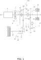
FIG. 1 is a schematic diagram showing a configuration of a hybrid vehicle transmission according to the present exemplary embodiment. -
FIG. 2 is a table showing exemplary gear shift patterns. -
FIG. 3 is a diagram showing a torque flow in gear shift pattern No. 1. -
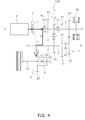
FIG. 4 is a diagram showing a torque flow in gear shift pattern No. 2. -
FIG. 5 is a diagram showing a torque flow in gear shift pattern No. 3. -
FIG. 6 is a diagram showing a torque flow in gear shift pattern No. 4. -
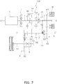
FIG. 7 is a diagram showing a torque flow in gear shift pattern No. 5. -
FIG. 8 is a diagram showing a torque flow in gear shift pattern No. 6. -
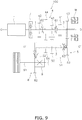
FIG. 9 is a diagram showing a torque flow in gear shift pattern No. 7. -
FIG. 10 is a diagram showing a torque flow in gear shift pattern No. 8. -
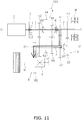
FIG. 11 is a diagram showing torque flows in gear shift pattern No. 9. -
FIG. 12 is a diagram showing torque flows in gear shift pattern No. 10. -
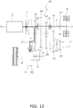
FIG. 13 is a diagram showing torque flows in gear shift pattern No. 11. -
FIG. 14 is a diagram showing torque flows in gear shift pattern No. 12. -
FIG. 15 is a diagram showing torque flows in gear shift pattern No. 13. -
FIG. 16 is a diagram showing torque flows in gear shift pattern No. 14. -
FIG. 17 is a diagram showing torque flows in gear shift pattern No. 15. -
FIG. 18 is a diagram showing torque flows in gear shift pattern No. 16. -
FIG. 19 is a diagram showing a torque flow in gear shift pattern No. 17. -
FIG. 20 is a diagram showing torque flows in gear shift pattern No. 18. -
FIG. 21 is a schematic diagram showing a configuration of a hybrid vehicle transmission according to a modification. - An exemplary embodiment of a hybrid vehicle transmission according to the present invention will be hereinafter explained with reference to drawings.
- As shown in
FIG. 1 , ahybrid vehicle transmission 100 has a plurality of gear stages. In the present exemplary embodiment, thehybrid vehicle transmission 100 has four gear stages. Additionally, thehybrid vehicle transmission 100 further has a reverse gear stage for backward movement provided separately from the four stage gears. - The
hybrid vehicle transmission 100 is configured to output rotation of each of an engine E and an electric motor M after the rotation is changed in speed therethrough. Thehybrid vehicle transmission 100 includes afirst input shaft 1, asecond input shaft 2, anoutput shaft 3, aninput gear train 4, anoutput gear train 5,a first synchromesh mechanism 61 (exemplary input shaft coupling means), a second synchromesh mechanism 62 (exemplary input gear coupling means), a third synchromesh mechanism 63 (exemplary output gear coupling means) and aclutch 7. - The
first input shaft 1 is a component to which a torque transmitted from the engine E is inputted. Detailedly, thefirst input shaft 1 is connected to the engine E through theclutch 7. Transmission of the torque from the engine E to thefirst input shaft 1 can be allowed or blocked by operating theclutch 7. Thefirst input shaft 1 is disposed to be rotated about a rotational axis O. Theclutch 7 is, for instance, a dry friction clutch. - The
second input shaft 2 is a component to which a torque transmitted from the electric motor M is inputted. Thesecond input shaft 2 is disposed coaxially to thefirst input shaft 1. Thesecond input shaft 2 is disposed to be rotated about the rotational axis O. - The
output shaft 3 is disposed in parallel to thefirst input shaft 1 and thesecond input shaft 2. Theoutput shaft 3 is disposed to be rotated about a rotational axis O'. - The
input gear train 4 includes a plurality of input gears provided in correspondence to the respective gear stages. Specifically, theinput gear train 4 includes a firststage input gear 41, a secondstage input gear 42, a thirdstage input gear 43 and a fourthstage input gear 44. In the input gears, those corresponding to odd-numbered stages are supported by thesecond input shaft 2. In other words, the firststage input gear 41 and the thirdstage input gear 43 are supported by thesecond input shaft 2. On the other hand, in the input gears , those corresponding to even-numbered stages are supported by thefirst input shaft 1. In other words, the secondstage input gear 42 and the fourthstage input gear 44 are supported by thefirst input shaft 1. - Additionally, the
input gear train 4 includes stationary input gears and movable input gears. In the input gears, the stationary input gears are those attached to be rotated unitarily with either thefirst input shaft 1 or thesecond input shaft 2. Specifically, the firststage input gear 41 and the thirdstage input gear 43 are the stationary input gears. The firststage input gear 41 and the thirdstage input gear 43 are attached to be rotated unitarily with thesecond input shaft 2. - In the input gears, the movable input gears are those attached to be rotated relatively to either the
first input shaft 1 or thesecond input shaft 2. Specifically, the secondstage input gear 42 and the fourthstage input gear 44 are the movable input gears. The secondstage input gear 42 and the fourthstage input gear 44 are attached to be rotated relatively to thefirst input shaft 1. - Additionally, the
input gear train 4 further includes areverse input gear 45. Thereverse input gear 45 is attached as a movable input gear to be rotated relatively to thefirst input shaft 1. - The
output gear train 5 includes a plurality of output gears provided in correspondence to the respective gear stages. Specifically, theoutput gear train 5 includes a firststage output gear 51, a secondstage output gear 52, a thirdstage output gear 53 and a fourthstage output gear 54. The respective output gears 51 to 54 are supported by theoutput shaft 3. It should be noted that the firststage output gear 51 is meshed with the firststage input gear 41; the secondstage output gear 52 is meshed with the secondstage input gear 42; the thirdstage output gear 53 is meshed with the thirdstage input gear 43; and the fourthstage output gear 54 is meshed with the fourthstage input gear 44. - Additionally, the
output gear train 5 includes stationary output gears and movable output gears. In the output gears, the stationary output gears are those attached to be rotated unitarily with theoutput shaft 3. Specifically, the secondstage output gear 52 and the fourthstage output gear 54 are the stationary output gears. The secondstage output gear 52 and the fourthstage output gear 54 are attached to be rotated unitarily with theoutput shaft 3. - In the output gears, the movable output gears are those attached to be rotated relatively to the
output shaft 3. Specifically, the firststage output gear 51 and the thirdstage output gear 53 are the movable output gears. The firststage output gear 51 and the thirdstage output gear 53 are attached to be rotated relatively to theoutput shaft 3. - Additionally, the
output gear train 5 further includes areverse output gear 55. Thereverse output gear 55 is attached as a stationary output gear to be rotated unitarily with theoutput shaft 3. Thereverse output gear 55 is meshed with thereverse input gear 45 through anidler gear 56. - The
first synchromesh mechanism 61 is configured to couple thefirst input shaft 1 and thesecond input shaft 2 while being capable of decoupling the both. Specifically, thefirst synchromesh mechanism 61 selectively couples either thesecond input shaft 2 or thereverse input gear 45 to thefirst input shaft 1, and also, decouples the both from each other. - The
second synchromesh mechanism 62 is configured to couple predetermined one of the movable input gears to and thefirst input shaft 1 and decouple the both from each other. Specifically, thesecond synchromesh mechanism 62 is attached to thefirst input shaft 1. Thesecond synchromesh mechanism 62 selectively couples either the secondstage input gear 42 or the fourthstage input gear 44 to thefirst input shaft 1, and decouples the both from each other. - The
third synchromesh mechanism 63 is configured to couple predetermined one of the movable output gears to theoutput shaft 3 and decouple the both from each other. Specifically, thethird synchromesh mechanism 63 is attached to theoutput shaft 3. Thethird synchromesh mechanism 63 selectively couples either the firststage output gear 51 or the thirdstage output gear 53 to theoutput shaft 3, and decouples the both from each other. - Additionally, the
hybrid vehicle transmission 100 further includes afinal gear train 8. Thefinal gear train 8 includes afinal drive gear 81 and a final drivengear 82. Thefinal drive gear 81 is attached to theoutput shaft 3 so as to be rotated unitarily therewith. The final drivengear 82 is fixed to an input shaft (axle) 91 of adifferential gear 9, and is meshed with thefinal drive gear 81. - An action of the
hybrid vehicle transmission 100 configured as described above will be explained.FIG. 2 shows actions of theclutch 7 and the first tothird synchromesh mechanisms 61 to 63 and gear ratios in the respective gear shift patterns. - It should be noted that in
FIG. 2 , "syn1··o" indicates that thesecond synchromesh mechanism 62 is actuated to couple the secondstage input gear 42 and thefirst input shaft 1. Likewise, "syn2··o" indicates that thesecond synchromesh mechanism 62 is actuated to couple the fourthstage input gear 44 and thefirst input shaft 1; "syn3··o" indicates that thefirst synchromesh mechanism 61 is actuated to couple thereverse input gear 45 and thefirst input shaft 1; "syn4··o" indicates that thefirst synchromesh mechanism 61 is actuated to couple thefirst input shaft 1 and thesecond input shaft 2; "syn5··o" indicates that thethird synchromesh mechanism 63 is actuated to couple the firststage output gear 51 and theoutput shaft 3; and "syn6··o" indicates that thethird synchromesh mechanism 63 is actuated to couple the thirdstage output gear 53 and theoutput shaft 3. On the other hand, "CL1··o" indicates that theclutch 7 is engaged such that the torque from the engine E is transmitted to thefirst input shaft 1. - In fields of gear ratios ("GEAR" and "ex. GEAR RATIO"), a row "1··3.5" indicates that a first stage gear ratio (the number of teeth of the first
stage output gear 51/the number of teeth of the first stage input gear 41) is "3.5", and likewise, subsequent rows indicate that second to fourth stage gear ratios are "2.4", "1.2" and "0.8", respectively. A row "F··3" indicates that the gear ratio of thefinal gear train 8 is "3". On the other hand, a row "Rev··4" indicates that the gear ratio in backward movement (the number of teeth of thereverse output gear 55/the number of teeth of the reverse input gear 45) is "4". It should be noted that values of the respective gear ratios are exemplary only, and are not limited to the above. - Gear shift patters Nos. 1 to 4 are used in traveling by the engine E; gear shift patterns Nos. 5 to 8 are used in traveling by the electric motor M; gear shift patterns Nos. 9 to 16 are used in traveling by the engine E and the electric motor M; gear shift pattern No. 17 is used in backward movement by the engine E; and gear shift pattern No. 18 is used in starting of the engine E and power generation by the electric motor M.
- As shown in
FIG. 2 , in the gear shift pattern No. 1, the torque from the engine E is transmitted to thefirst input shaft 1 in theclutch 7. Additionally, thefirst input shaft 1 and thesecond input shaft 2 are coupled by thefirst synchromesh mechanism 61. Moreover, the firststage output gear 51 is coupled to theoutput shaft 3 by thethird synchromesh mechanism 63. - In this case, as indicated with a bold line in
FIG. 3 , the torque from the engine E is transmitted through a path of "the engine E → thefirst input shaft 1 → thesecond input shaft 2 → the firststage input gear 41 → the firststage output gear 51 → theoutput shaft 3 → thefinal gear train 8". The gear ratio in this path is as follows.
- As shown in
FIG. 2 , in the gear shift pattern No. 2, the torque from the engine E is transmitted to thefirst input shaft 1 in theclutch 7. Additionally, the secondstage input gear 42 is coupled to thefirst input shaft 1 by thesecond synchromesh mechanism 62. - In this case, as indicated with a bold line in
FIG. 4 , the torque from the engine E is transmitted through a path of "the engine E → thefirst input shaft 1 → the secondstage input gear 42 → the secondstage output gear 52 → theoutput shaft 3 → thefinal gear train 8". The gear ratio in this path is as follows.
- As shown in
FIG. 2 , in the gear shift pattern No. 3, the torque from the engine E is transmitted to thefirst input shaft 1 in theclutch 7. Additionally, thefirst input shaft 1 and thesecond input shaft 2 are coupled by thefirst synchromesh mechanism 61. Moreover, the thirdstage output gear 53 is coupled to theoutput shaft 3 by thethird synchromesh mechanism 63. - In this case, as indicated with a bold line in
FIG. 5 , the torque from the engine E is transmitted through a path of "the engine E → thefirst input shaft 1 → thesecond input shaft 2 → the thirdstage input gear 43 → the thirdstage output gear 53 → theoutput shaft 3 → thefinal gear train 8". The gear ratio in this path is as follows. (Gear 3: 1.2)×(Gear F: 3)=3.6 - As shown in
FIG. 2 , in the gear shift pattern No. 4, the torque from the engine E is transmitted to thefirst input shaft 1 in theclutch 7. Additionally, the fourthstage input gear 44 is coupled to thefirst input shaft 1 by thesecond synchromesh mechanism 62. - In this case, as indicated with a bold line in
FIG. 6 , the torque from the engine E is transmitted through a path of "the engine E → thefirst input shaft 1 → the fourthstage input gear 44 → the fourthstage output gear 54 → theoutput shaft 3 → thefinal gear train 8". The gear ratio in this path is as follows.
- As shown in
FIG. 2 , in the gear shift pattern No. 5, the torque from the engine E is blocked from being transmitted to thefirst input shaft 1 in theclutch 7. Additionally, the firststage output gear 51 is coupled to theoutput shaft 3 by thethird synchromesh mechanism 63. - In this case, as indicated with a dotted line in
FIG. 7 , the torque from the electric motor M is transmitted through a path of "the electric motor M → thesecond input shaft 2 → the firststage input gear 41 → the firststage output gear 51 → theoutput shaft 3 → thefinal gear train 8". The gear ratio in this path is as follows.
- As shown in
FIG. 2 , in the gear shift pattern No. 6, the torque from the engine E is blocked from being transmitted to thefirst input shaft 1 in theclutch 7. Additionally, thefirst input shaft 1 and thesecond input shaft 2 are coupled by thefirst synchromesh mechanism 61. Moreover, the secondstage input gear 42 is coupled to thefirst input shaft 1 by thesecond synchromesh mechanism 62. - In this case, as indicated with a dotted line in
FIG. 8 , the torque from the electric motor M is transmitted through a path of "the electric motor M → thesecond input shaft 2 → thefirst input shaft 1 → the secondstage input gear 42 → the secondstage output gear 52 → theoutput shaft 3 → thefinal gear train 8". The gear ratio in this path is as follows.
- As shown in
FIG. 2 , in the gear shift pattern No. 7, the torque from the engine E is blocked from being transmitted to thefirst input shaft 1 in theclutch 7. Additionally, the thirdstage output gear 53 is coupled to theoutput shaft 3 bythird synchromesh mechanism 63. - In this case, as indicated with a dotted line in
FIG. 9 , the torque from the electric motor M is transmitted through a path of "the electric motor M → thesecond input shaft 2 → the thirdstage input gear 43 → the thirdstage output gear 53 → theoutput shaft 3 → thefinal gear train 8". The gear ratio in this path is as follows.
- As shown in
FIG. 2 , in the gear shift pattern No. 8, the torque from the engine E is blocked from being transmitted to thefirst input shaft 1 in theclutch 7. Additionally, thefirst input shaft 1 and thesecond input shaft 2 are coupled by thefirst synchromesh mechanism 61. Moreover, the fourthstage input gear 44 is coupled to thefirst input shaft 1 by thesecond synchromesh mechanism 62. - In this case, as indicated with a dotted line in
FIG. 10 , the torque from the electric motor M is transmitted through a path of "the electric motor M → thesecond input shaft 2 → thefirst input shaft 1 → the fourthstage input gear 44 → the fourthstage output gear 54 → theoutput shaft 3 → thefinal gear train 8". The gear ratio in this path is as follows.
- As shown in
FIG. 2 , in the gear shift pattern No. 9, the torque from the engine E is transmitted to thefirst input shaft 1 in theclutch 7. Additionally, thefirst input shaft 1 and thesecond input shaft 2 are coupled by thefirst synchromesh mechanism 61. Moreover, the firststage output gear 51 is coupled to theoutput shaft 3 by thethird synchromesh mechanism 63. - In this case, as indicated with a bold line in
FIG. 11 , the torque from the engine E is transmitted through a path of "the engine E → thefirst input shaft 1 → thesecond input shaft 2 → the firststage input gear 41 → the firststage output gear 51 → theoutput shaft 3 → thefinal gear train 8". The gear ratio in this path is as follows.
- On the other hand, as indicated with a dotted line in
FIG. 11 , the torque from the electric motor M is transmitted through a path of "the electric motor M → thesecond input shaft 2 → the firststage input gear 41 → the firststage output gear 51 → theoutput shaft 3 → thefinal gear train 8". The gear ratio in this path is as follows.
- As shown in
FIG. 2 , in the gear shift pattern No. 10, the torque from the engine E is transmitted to thefirst input shaft 1 in theclutch 7. Additionally, the secondstage input gear 42 is coupled to thefirst input shaft 1 by thesecond synchromesh mechanism 62. Moreover, the firststage output gear 51 is coupled to theoutput shaft 3 by thethird synchromesh mechanism 63. - In this case, as indicated with a bold line in
FIG. 12 , the torque from the engine E is transmitted through a path of "the engine E → thefirst input shaft 1 → the secondstage input gear 42 → the secondstage output gear 52 → theoutput shaft 3 → thefinal gear train 8". The gear ratio in this path is as follows.
- On the other hand, as indicated with a dotted line in
FIG. 12 , the torque from the electric motor M is transmitted through a path of "the electric motor M → thesecond input shaft 2 → the firststage input gear 41 → the firststage output gear 51 → theoutput shaft 3 → thefinal gear train 8". The gear ratio in this path is as follows.
- As shown in
FIG. 2 , in the gear shift pattern No. 11, the torque from the engine E is transmitted to thefirst input shaft 1 in theclutch 7. Additionally, thefirst input shaft 1 and thesecond input shaft 2 are coupled by thefirst synchromesh mechanism 61. Moreover, the secondstage input gear 42 is coupled to thefirst input shaft 1 by thesecond synchromesh mechanism 62. - In this case, as indicated with a bold line in
FIG. 13 , the torque from the engine E is transmitted through a path of "the engine E → thefirst input shaft 1 → the secondstage input gear 42 → the secondstage output gear 52 → theoutput shaft 3 → thefinal gear train 8". The gear ratio in this path is as follows.
- On the other hand, as indicated with a dotted line in
FIG. 13 , the torque from the electric motor M is transmitted through a path of "the electric motor M → thesecond input shaft 2 → thefirst input shaft 1 → the secondstage input gear 42 → the secondstage output gear 52 → theoutput shaft 3 → thefinal gear train 8". The gear ratio in this path is as follows.
- As shown in
FIG. 2 , in the gear shift pattern No. 12, the torque from the engine E is transmitted to thefirst input shaft 1 in theclutch 7. Additionally, the secondstage input gear 42 is coupled to thefirst input shaft 1 by thesecond synchromesh mechanism 62. Moreover, the thirdstage output gear 53 is coupled to theoutput shaft 3 by thethird synchromesh mechanism 63. - In this case, as indicated with a bold line in
FIG. 14 , the torque from the engine E is transmitted through a path of "the engine E → thefirst input shaft 1 → the secondstage input gear 42 → the secondstage output gear 52 → theoutput shaft 3 → thefinal gear train 8". The gear ratio in this path is as follows.
- On the other hand, as indicated with a dotted line in
FIG. 14 , the torque from the electric motor M is transmitted through a path of "the electric motor M → thesecond input shaft 2 → the thirdstage input gear 43 → the thirdstage output gear 53 → theoutput shaft 3 → thefinal gear train 8". The gear ratio in this path is as follows.
- As shown in
FIG. 2 , in the gear shift pattern No. 13, the torque from the engine E is transmitted to thefirst input shaft 1 in theclutch 7. Additionally, thefirst input shaft 1 and thesecond input shaft 2 are coupled by thefirst synchromesh mechanism 61. Moreover, the thirdstage output gear 53 is coupled to theoutput shaft 3 by thethird synchromesh mechanism 63. - In this case, as indicated with a bold line in
FIG. 15 , the torque from the engine E is transmitted through a path of "the engine E → thefirst input shaft 1 → thesecond input shaft 2 → the thirdstage input gear 43 → the thirdstage output gear 53 → theoutput shaft 3 → thefinal gear train 8". The gear ratio in this path is as follows.
- On the other hand, as indicated with a dotted line in
FIG. 15 , the torque from the electric motor M is transmitted through a path of "the electric motor M → thesecond input shaft 2 → the thirdstage input gear 43 → the thirdstage output gear 53 → theoutput shaft 3 → thefinal gear train 8". The gear ratio in this path is as follows.
- As shown in
FIG. 2 , in the gear shift pattern No. 14, the torque from the engine E is transmitted to thefirst input shaft 1 in theclutch 7. Additionally, the fourthstage input gear 44 is coupled to thefirst input shaft 1 by thesecond synchromesh mechanism 62. Moreover, the firststage output gear 51 is coupled to theoutput shaft 3 by thethird synchromesh mechanism 63. - In this case, as indicated with a bold line in
FIG. 16 , the torque from the engine E is transmitted through a path of "the engine E → thefirst input shaft 1 → the fourthstage input gear 44 → the fourthstage output gear 54 → theoutput shaft 3 → thefinal gear train 8". The gear ratio in this path is as follows.
- On the other hand, as indicated with a dotted line in
FIG. 16 , the torque from the electric motor M is transmitted through a path of "the electric motor M → thesecond input shaft 2 → the firststage input gear 41 → the firststage output gear 51 → theoutput shaft 3 → thefinal gear train 8". The gear ratio in this path is as follows.
- As shown in
FIG. 2 , in the gear shift pattern No. 15, the torque from the engine E is transmitted to thefirst input shaft 1 in theclutch 7. Additionally, the fourthstage input gear 44 is coupled to thefirst input shaft 1 by thesecond synchromesh mechanism 62. Moreover, the thirdstage output gear 53 is coupled to theoutput shaft 3 by thethird synchromesh mechanism 63. - In this case, as indicated with a bold line in
FIG. 17 , the torque from the engine E is transmitted through a path of "the engine E → thefirst input shaft 1 → the fourthstage input gear 44 → the fourthstage output gear 54 → theoutput shaft 3 → thefinal gear train 8". The gear ratio in this path is as follows.
- On the other hand, as indicated with a dotted line in
FIG. 17 , the torque from the electric motor M is transmitted through a path of "the electric motor M → thesecond input shaft 2 → the thirdstage input gear 43 → the thirdstage output gear 53 → theoutput shaft 3 → thefinal gear train 8". The gear ratio in this path is as follows.
- As shown in
FIG. 2 , in the gear shift pattern No. 16, the torque from the engine E is transmitted to thefirst input shaft 1 in theclutch 7. Additionally, thefirst input shaft 1 and thesecond input shaft 2 are coupled by thefirst synchromesh mechanism 61. Moreover, the fourthstage input gear 44 is coupled to thefirst input shaft 1 by thesecond synchromesh mechanism 62. - In this case, as indicated with a bold line in
FIG. 18 , the torque from the engine E is transmitted through a path of "the engine E → thefirst input shaft 1 → the fourthstage input gear 44 → the fourthstage output gear 54 → theoutput shaft 3 → thefinal gear train 8". The gear ratio in this path is as follows.
- On the other hand, as indicated with a dotted line in
FIG. 18 , the torque from the electric motor M is transmitted through a path of "the electric motor M → thesecond input shaft 2 → thefirst input shaft 1 → the fourthstage input gear 44 → the fourthstage output gear 54 → theoutput shaft 3 → thefinal gear train 8". The gear ratio in this path is as follows.
- As shown in
FIG. 2 , in the gear shift pattern No. 17, the torque from the engine E is transmitted to thefirst input shaft 1 in theclutch 7. Additionally, thereverse input gear 45 is coupled to thefirst input shaft 1 by thefirst synchromesh mechanism 61. - In this case, as indicated with a bold line in
FIG. 19 , the torque from the engine E is transmitted through a path of "the engine E → thefirst input shaft 1 → thereverse input gear 45 → theidler gear 56 → thereverse output gear 55 → theoutput shaft 3 → thefinal gear train 8". The gear ratio in this path is as follows.
- As shown in
FIG. 2 , in the gear shift pattern No. 18, the torque from the engine E is transmitted to thefirst input shaft 1 in theclutch 7. Additionally, thefirst input shaft 1 and thesecond input shaft 2 are coupled by thefirst synchromesh mechanism 61. - In generating electric power by the electric motor M, as indicated with a bold line in
FIG. 20 , the torque from the engine E is transmitted through a path of "the engine E → thefirst input shaft 1 → thesecond input shaft 2 → the electric motor M". - On the other hand, in starting of the engine E, as indicated with a dotted line in
FIG. 20 , the torque from the electric motor M is transmitted through a path of "the electric motor M → thesecond input shaft 2 → thefirst input shaft 1 → the engine E". - One exemplary embodiment of the present invention has been explained above. However, the present invention is not limited to the aforementioned exemplary embodiment, and a variety of changes can be made without departing from the gist of the present invention.
- In the aforementioned exemplary embodiment, the electric motor M is directly connected to the
second input shaft 2. However, the configuration to connect the electric motor M is not limited to the above. For example, thesecond input shaft 2 may be connected to an output shaft of the electric motor M through a gear and so forth. Specifically, as shown inFIG. 21 , thehybrid vehicle transmission 100 further includes athird input shaft 101, adrive gear 102 and a drivengear 103. Thethird input shaft 101 is disposed in parallel to thesecond input shaft 2. Thethird input shaft 101 is a component to which the electric motor M is connected. Thedrive gear 102 is rotated unitarily with thethird input shaft 101. The drivengear 103 is rotated unitarily with thesecond input shaft 2, and is meshed with thedrive gear 102. - The gear shift patterns in the aforementioned exemplary embodiment are exemplary only, and a variety of gear shift patterns can be realized.
- In the aforementioned exemplary embodiment, the
hybrid vehicle transmission 100 has four gear stages, but may have five or more gear stages or three or less gear stages. - In the aforementioned exemplary embodiment, the input gears corresponding to the even-numbered gear stages are supported by the
first input shaft 1, whereas the input gears corresponding to the odd-numbered gear stages are supported by thesecond input shaft 2. However, the positional relation between the former input gears and the latter input gears may be reversed. - In the aforementioned exemplary embodiment, the
second synchromesh mechanism 62 is attached to thefirst input shaft 1, whereas thethird synchromesh mechanism 63 is attached to theoutput shaft 3. However, the layout of thesecond synchromesh mechanism 62 and thethird synchromesh mechanism 63 is not limited to the above. For example, thesecond synchromesh mechanism 62 may be attached to theoutput shaft 3, whereas thethird synchromesh mechanism 63 may be attached to thesecond input shaft 2. -
- 1
- First input shaft
- 2
- Second input shaft
- 3
- Output shaft
- 41
- First stage input gear
- 42
- Second stage input gear
- 43
- Third stage input gear
- 44
- Fourth stage input gear
- 51
- First stage output gear
- 52
- Second stage output gear
- 53
- Third stage output gear
- 54
- Fourth stage output gear
- 61
- First synchromesh mechanism
- 100
- Hybrid vehicle transmission
- E
- Engine
- M
- Electric motor
Claims (13)
- A hybrid vehicle transmission having a plurality of gear stages, the hybrid vehicle transmission outputting rotation of each of an engine and an electric motor after the rotation is changed in speed therethrough, the hybrid vehicle transmission comprising:a first input shaft to which a torque is inputted from the engine;a second input shaft to which a torque is inputted from the electric motor, the second input shaft being disposed coaxially to the first input shaft;an output shaft disposed in parallel to the first and second input shafts;a plurality of input gears provided in correspondence to the plurality of gear stages, the plurality of input gears being each supported by either the first input shaft or the second input shaft;a plurality of output gears provided in correspondence to the plurality of gear stages, the plurality of output gears being supported by the output shaft; andinput shaft coupling means configured to couple the first input shaft and the second input shaft while being capable of decoupling the first input shaft and the second input shaft.
- The hybrid vehicle transmission according to claim 1, further comprising:input gear coupling means, whereinthe plurality of input gears include a stationary input gear and a movable input gear, the stationary input gear being attached to either the first input shaft or the second input shaft so as to be rotated unitarily therewith, the movable input gear being attached to either the first input shaft or the second input shaft so as to be rotated relatively thereto, andthe input gear coupling means is configured to couple the movable input gear to either the first input shaft or the second input shaft and decouple the movable input gear therefrom.
- The hybrid vehicle transmission according to claim 1 or 2, further comprising:output gear coupling means, whereinthe plurality of output gears include a stationary output gear and a movable output gear, the stationary output gear being attached to the output shaft so as to be rotated unitarily therewith, the movable output gear being attached to the output shaft so as to be rotated relatively thereto, andthe output gear coupling means is configured to couple the movable output gear to the output shaft and decouple the movable output gear therefrom.
- The hybrid vehicle transmission according to any of claims 1 to 3, wherein
one input gear of the plurality of input gears corresponds to odd-numbered one of the plurality of gear stages, the one input gear being supported by one of the first input shaft and the second input shaft, and
another input gear of the plurality of input gears corresponds to even-numbered one of the plurality of gear stages, the another input gear being supported by the other of the first input shaft and the second input shaft. - The hybrid vehicle transmission according to any of claims 1 to 3, wherein
one input gear of the plurality of input gears corresponds to odd-numbered one of the plurality of gear stages, the one input gear being supported by the second input shaft, and
another input gear of the plurality of input gears corresponds to even-numbered one of the plurality of gear stages, the another input gear being supported by the first input shaft. - The hybrid vehicle transmission according to any of claims 1 to 5, wherein the plurality of gear stages are four gear stages.
- The hybrid vehicle transmission according to any of claims 1 to 6, further comprising:
a reverse gear stage for backward movement provided separately from the plurality of gear stages. - The hybrid vehicle transmission according to any of claims 1 to 7, wherein the input shaft coupling means is a synchromesh mechanism.
- The hybrid vehicle transmission according to claim 2, wherein the input gear coupling means is a synchromesh mechanism.
- The hybrid vehicle transmission according to claim 3, wherein the output gear coupling means is a synchromesh mechanism.
- The hybrid vehicle transmission according to any of claims 1 to 10, further comprising:
a clutch configured to allow and block transmission of the torque from the engine to the first input shaft therethrough. - The hybrid vehicle transmission according to claim 11, wherein the clutch is a dry friction clutch.
- The hybrid vehicle transmission according to any of claims 1 to 12, further comprising:a third input shaft to which the electric motor is connected, the third input shaft being disposed in parallel to the second input shaft;a drive gear rotated unitarily with the third input shaft; anda driven gear rotated unitarily with the second input shaft, the driven gear being meshed with the drive gear.
Applications Claiming Priority (2)
| Application Number | Priority Date | Filing Date | Title |
|---|---|---|---|
| JP2017046342A JP2018149871A (en) | 2017-03-10 | 2017-03-10 | Transmission for hybrid vehicle |
| PCT/JP2018/007708 WO2018163949A1 (en) | 2017-03-10 | 2018-03-01 | Hybrid vehicle transmission |
Publications (1)
| Publication Number | Publication Date |
|---|---|
| EP3575115A1 true EP3575115A1 (en) | 2019-12-04 |
Family
ID=63448171
Family Applications (1)
| Application Number | Title | Priority Date | Filing Date |
|---|---|---|---|
| EP18763700.4A Withdrawn EP3575115A1 (en) | 2017-03-10 | 2018-03-01 | Hybrid vehicle transmission |
Country Status (5)
| Country | Link |
|---|---|
| US (1) | US20190337400A1 (en) |
| EP (1) | EP3575115A1 (en) |
| JP (1) | JP2018149871A (en) |
| CN (1) | CN110382271A (en) |
| WO (1) | WO2018163949A1 (en) |
Families Citing this family (5)
| Publication number | Priority date | Publication date | Assignee | Title |
|---|---|---|---|---|
| DE102019201298A1 (en) * | 2019-02-01 | 2020-08-06 | Zf Friedrichshafen Ag | Hybrid transmission for a motor vehicle |
| JP2021130426A (en) * | 2020-02-21 | 2021-09-09 | 三菱自動車工業株式会社 | Driving device |
| JP2021130425A (en) * | 2020-02-21 | 2021-09-09 | 三菱自動車工業株式会社 | Driving device |
| CN112937284A (en) * | 2021-03-24 | 2021-06-11 | 何亚芳 | Hybrid power transmission device |
| CN120517161A (en) * | 2025-07-25 | 2025-08-22 | 东风本田发动机有限公司 | Hybrid powertrains and vehicles |
Family Cites Families (3)
| Publication number | Priority date | Publication date | Assignee | Title |
|---|---|---|---|---|
| JP2005153691A (en) | 2003-11-26 | 2005-06-16 | Aisin Seiki Co Ltd | Vehicle drive mechanism |
| JP5660077B2 (en) * | 2010-07-08 | 2015-01-28 | 株式会社デンソー | Power transmission device for vehicle |
| JP5972091B2 (en) * | 2012-08-03 | 2016-08-17 | 本田技研工業株式会社 | Hybrid vehicle |
-
2017
- 2017-03-10 JP JP2017046342A patent/JP2018149871A/en not_active Withdrawn
-
2018
- 2018-03-01 EP EP18763700.4A patent/EP3575115A1/en not_active Withdrawn
- 2018-03-01 WO PCT/JP2018/007708 patent/WO2018163949A1/en not_active Ceased
- 2018-03-01 US US16/475,585 patent/US20190337400A1/en not_active Abandoned
- 2018-03-01 CN CN201880015959.9A patent/CN110382271A/en active Pending
Also Published As
| Publication number | Publication date |
|---|---|
| JP2018149871A (en) | 2018-09-27 |
| CN110382271A (en) | 2019-10-25 |
| WO2018163949A1 (en) | 2018-09-13 |
| US20190337400A1 (en) | 2019-11-07 |
Similar Documents
| Publication | Publication Date | Title |
|---|---|---|
| EP3575115A1 (en) | Hybrid vehicle transmission | |
| US9528583B2 (en) | Dual clutch gearbox with countershaft design | |
| CN103185113B (en) | Planetary gear type gearbox | |
| US9528572B2 (en) | Gear unit for a compound transmission | |
| EP2505408A1 (en) | Motive power transmission device | |
| JP2004522097A (en) | Multi-stage transmission | |
| CN101191535A (en) | Multi-speed transmission | |
| KR20010062671A (en) | Hybrid Drive Apparatus | |
| CN103547831B (en) | The parallel shift transmission of vehicle | |
| US20150087469A1 (en) | Multi-stage power-shift transmission | |
| US6969335B2 (en) | Automated gear transmission | |
| US11187310B2 (en) | Gear mechanism, use of a gear mechanism and method for a gear mechanism | |
| CN107120390B (en) | Dual clutch transmission for a motor vehicle | |
| WO2017121030A1 (en) | Semi-combinatory gear transmission | |
| JP2013072464A (en) | Automatic transmission | |
| EP2847494B1 (en) | Reversing double - flow gearbox arrangement, mainly for motor vehicles and construction machines, with two branches of output flow | |
| CN105299155A (en) | Modular transmission | |
| CN111051108A (en) | Transmission equipment for motor vehicles | |
| JP2016056894A (en) | Dual clutch transmission | |
| CN104114905A (en) | Automatic transmission device | |
| CN110603391B (en) | Transmission device for motor vehicle | |
| CN101358637B (en) | Multi-speed transmission | |
| US11209075B2 (en) | Transmission | |
| US9863501B2 (en) | Double clutch transmission | |
| CN105556167B (en) | Automatic transmission |
Legal Events
| Date | Code | Title | Description |
|---|---|---|---|
| PUAI | Public reference made under article 153(3) epc to a published international application that has entered the european phase |
Free format text: ORIGINAL CODE: 0009012 |
|
| 17P | Request for examination filed |
Effective date: 20190830 |
|
| AK | Designated contracting states |
Kind code of ref document: A1 Designated state(s): AL AT BE BG CH CY CZ DE DK EE ES FI FR GB GR HR HU IE IS IT LI LT LU LV MC MK MT NL NO PL PT RO RS SE SI SK SM TR |
|
| AX | Request for extension of the european patent |
Extension state: BA ME |
|
| DAV | Request for validation of the european patent (deleted) | ||
| DAX | Request for extension of the european patent (deleted) | ||
| STAA | Information on the status of an ep patent application or granted ep patent |
Free format text: STATUS: THE APPLICATION HAS BEEN WITHDRAWN |
|
| 18W | Application withdrawn |
Effective date: 20200616 |